EP2026406A1 - Multipurpose antenna unit - Google Patents
Multipurpose antenna unit Download PDFInfo
- Publication number
- EP2026406A1 EP2026406A1 EP07114288A EP07114288A EP2026406A1 EP 2026406 A1 EP2026406 A1 EP 2026406A1 EP 07114288 A EP07114288 A EP 07114288A EP 07114288 A EP07114288 A EP 07114288A EP 2026406 A1 EP2026406 A1 EP 2026406A1
- Authority
- EP
- European Patent Office
- Prior art keywords
- antenna unit
- antennas
- unit according
- antenna
- individual antennas
- Prior art date
- Legal status (The legal status is an assumption and is not a legal conclusion. Google has not performed a legal analysis and makes no representation as to the accuracy of the status listed.)
- Ceased
Links
Images
Classifications
-
- H—ELECTRICITY
- H01—ELECTRIC ELEMENTS
- H01Q—ANTENNAS, i.e. RADIO AERIALS
- H01Q7/00—Loop antennas with a substantially uniform current distribution around the loop and having a directional radiation pattern in a plane perpendicular to the plane of the loop
- H01Q7/06—Loop antennas with a substantially uniform current distribution around the loop and having a directional radiation pattern in a plane perpendicular to the plane of the loop with core of ferromagnetic material
- H01Q7/08—Ferrite rod or like elongated core
-
- H—ELECTRICITY
- H01—ELECTRIC ELEMENTS
- H01Q—ANTENNAS, i.e. RADIO AERIALS
- H01Q1/00—Details of, or arrangements associated with, antennas
- H01Q1/12—Supports; Mounting means
- H01Q1/22—Supports; Mounting means by structural association with other equipment or articles
- H01Q1/24—Supports; Mounting means by structural association with other equipment or articles with receiving set
- H01Q1/241—Supports; Mounting means by structural association with other equipment or articles with receiving set used in mobile communications, e.g. GSM
- H01Q1/242—Supports; Mounting means by structural association with other equipment or articles with receiving set used in mobile communications, e.g. GSM specially adapted for hand-held use
- H01Q1/243—Supports; Mounting means by structural association with other equipment or articles with receiving set used in mobile communications, e.g. GSM specially adapted for hand-held use with built-in antennas
-
- H—ELECTRICITY
- H01—ELECTRIC ELEMENTS
- H01Q—ANTENNAS, i.e. RADIO AERIALS
- H01Q1/00—Details of, or arrangements associated with, antennas
- H01Q1/27—Adaptation for use in or on movable bodies
- H01Q1/273—Adaptation for carrying or wearing by persons or animals
-
- H—ELECTRICITY
- H01—ELECTRIC ELEMENTS
- H01Q—ANTENNAS, i.e. RADIO AERIALS
- H01Q21/00—Antenna arrays or systems
- H01Q21/24—Combinations of antenna units polarised in different directions for transmitting or receiving circularly and elliptically polarised waves or waves linearly polarised in any direction
-
- H—ELECTRICITY
- H01—ELECTRIC ELEMENTS
- H01Q—ANTENNAS, i.e. RADIO AERIALS
- H01Q21/00—Antenna arrays or systems
- H01Q21/28—Combinations of substantially independent non-interacting antenna units or systems
-
- H—ELECTRICITY
- H04—ELECTRIC COMMUNICATION TECHNIQUE
- H04R—LOUDSPEAKERS, MICROPHONES, GRAMOPHONE PICK-UPS OR LIKE ACOUSTIC ELECTROMECHANICAL TRANSDUCERS; DEAF-AID SETS; PUBLIC ADDRESS SYSTEMS
- H04R2225/00—Details of deaf aids covered by H04R25/00, not provided for in any of its subgroups
- H04R2225/51—Aspects of antennas or their circuitry in or for hearing aids
Definitions
- the invention relates to a multipurpose antenna, i.e. a combined antenna having several sets of windings, which are each used individually for addressing different wireless interfaces.
- the invention relates specifically to: An antenna unit for wireless communication to a multitude of wireless interfaces comprising a multitude of individual antennas, each antenna comprising a coil comprising at least one winding and the individual antennas embrace the same volume.
- the invention may e.g. be useful in applications such as wireless communication devices, e.g. mobile telephones, head phones, head sets, hearing aids, etc.
- wireless communication devices e.g. mobile telephones, head phones, head sets, hearing aids, etc.
- Antennas having more than one set of windings are described in the prior at.
- GB-279,935 describes an antenna unit for use in wireless telecommunication, the unit comprising two frame windings having different natural wavelengths and arranged so that there is substantially no interaction between the said windings.
- US 7,123,206 describes a system comprising multiple antennas wound around a common core, adapted for use in an inductively coupled system for transmitting or receiving electromagnetic signals in three dimensions.
- DE 195 33 105 describes an antenna unit for a car comprising three coils, which are perpendicular to each other and adapted for receiving horizontally as well as vertically polarized signals (e.g. TV and radio signals, respectively).
- Examples of such applications are hearing aids, personal communication devices, and other miniature wireless equipment.
- antennas for multiple (e.g. 2 or more, e.g. 3) wireless interfaces into a single antenna unit by placing several sets of windings, each specific for the individual wireless interface, around a common volume (a former core for forming and/or supporting the antennas is optional).
- the object of the present invention is to provide an antenna unit providing several wireless interfaces at a relatively small volume.
- An object of the invention is achieved by An antenna unit for wireless communication to a multitude of wireless interfaces comprising a multitude of individual antennas, each antenna comprising a coil comprising at least one winding and the individual antennas embrace the same volume.
- at least one of the coils is adapted for providing an inductive coupling to another device.
- the mutual coupling between antennas of the unit can be controlled by the angle of the windings.
- the individual coils are preferably arranged in such a way that there is ideally no coupling between windings, e.g. in perpendicular planes.
- the combination of several antennas in a single component has the advantage of removing relative placement accuracy requirements between individual antennas, hence the spread in mutual influence is defined by the component alone and is not affected by manual operators or machine processes.
- the antenna unit can be pre-tested on a component level and subsequently yield loss can e.g. be minimised in the assembly process.
- At least one of the antennas is adapted for communication with another device based on electromagnetic radiation.
- the individual antennas share the same volume in that the windings of the individual antennas are wound around the same common volume so that the windings of two arbitrary antennas cross each other when viewed in an appropriate cross-sectional plane.
- the antenna unit comprises 2 or 3 or more individual antennas. In an embodiment, the antenna unit has 2 individual antennas. In an embodiment, the antenna unit has 3 individual antennas. In an embodiment, at least one of the 2 or 3 individual antennas is/are an RF-antenna (not adapted for inductive coupling to the other relatively closely positioned device to which at least one of the antennas is/are adapted to be inductively coupled).
- the mutual coupling between two individual antennas is controlled by the mutual angle of the windings of the two antennas when viewed in an appropriate cross sectional plane.
- the windings of two individual antennas are substantially perpendicular to each other.
- the windings of the individual antennas are wound around a common former.
- the common former comprises a flux amplifying material, e.g. a ceramic material, e.g. a ferrite material.
- the at least one coil for inductive coupling is optimized to a predefined frequency range.
- the antenna unit comprises a tuning circuit for optimizing the frequency range.
- at least one of the induction coils of the antenna unit is/are adapted to provide a specific preferred frequency range for the inductive communication by adapting at least one of the cross-sectional area, the number of turns, the choice of core material in the coil, the values of a capacitor and/or a resistor of a resonance circuit formed by the coil, the capacitor and/or the resistor.
- the transmission frequency for use in the inductive communication is selected to provide that the distance of the transmission (i.e. the distance between the inductively coupled transmitting and receiving coils) and the dimensions of the coils are relatively small compared to the wavelength of transmission frequency.
- the physical dimensions of the coils are in the range from 10 to 100 times smaller than the wavelength of transmission frequency, such as between 30 and 70 times smaller.
- Inductive transmission can in general be performed in any part of the MF- or HF-bands e.g. in the MHz-range, preferably at frequencies below 100 MHz, such as at frequencies below 30 MHz, e.g. in the range between 300 kHz (or even lower) and 30 MHz, such as in the range between 1 MHz and 20 MHz.
- the at least one coil being adapted for providing an inductive coupling to another device is adapted to operate around 4 MHz.
- the RF-transmission can in general be performed in any part of the RF band, e.g. in the VHF-band.
- the at least one coil being adapted for communication with another device based on electromagnetic radiation is adapted to operate around 200 MHz.
- a mobile telephone comprising an antenna unit as described above, in the detailed description below and in the claims is provided.
- a hearing aid comprising an antenna unit as described above, in the detailed description below and in the claims is provided.
- the at least one coil being adapted for providing an inductive coupling to another device is adapted to receive signals from the other device (in addition to transmitting signals to the other device).
- At least one of the at least one coil being adapted for communication with another device based on electromagnetic radiation is adapted to receive signals from the other device (in addition to transmitting signals to the other device).
- the other device is a communications device, such as a mobile telephone, an audio selection device or the like.
- An antenna unit according to the invention can e.g. be used in a head-worn audio device, such as a hearing aid, for providing communication to another device (e.g. another hearing aid in a binaural system) e.g. using an inductive coupling.
- a head-worn audio device such as a hearing aid
- another device e.g. another hearing aid in a binaural system
- inductive communication between a fist head-worn audio device could be used to an external device for programming the audio device, an audio selection device, wherein an audio signal can be selected among a number of audio signals received by the audio selection device (possibly including a signal from a mobile telephone or from a radio or music player, e.g. a MP3-palyer or the like).
- FM-transmision can e.g. be useful between a head-worn audio device and a wireless microphone (e.g.
- an antenna unit in a classroom amplification or conference system, or a TV, radio, music player, etc.
- a device e.g. a hearing aid
- minimum space (volume) is an important parameter.
- the tolerances for the relative mutual placement of various coils can be handled in one unit and thus generally relaxed.
- an antenna unit according to the invention is included in a hearing aid.
- one of the interfaces of the antenna unit is to a telecoil for receiving a 'broadcast' signal.
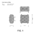
- Fig. 1 shows an antenna unit according to an embodiment of the invention.
- the drawing illustrates an antenna according to an embodiment of the invention comprising two sets of windings placed in perpendicular planes on a common antenna core, comprising a flux amplifying material, e.g. a magnetically soft material, e.g. comprising iron, e.g. a ceramic core.
- a flux amplifying material e.g. a magnetically soft material, e.g. comprising iron, e.g. a ceramic core.
- a ceramic core can be adapted to have good magnetic properties AND to be mechanically stable.
- the dimension of the antenna unit is 5 mm x 5.5 mm x 2.5 mm.
- One coil has a relatively low inductance, here 160 nH (implemented by 3 turns of a 0.3 mm diameter Cu-wire) and is intended for reception of a ⁇ 200 MHz FM signal (i.e. TEM dominant field).
- the other coil here being wound perpendicularly to the first coil, has a higher inductance, here 19 ⁇ H (implemented by 50 turns of a 0.08 mm Cu-wire) and is intended for reception of a ⁇ 4 MHz magnetic link (i.e. M dominant field).
- the transmission frequency for use in the inductive communication is selected with a view to the rate of data transmission needed, the transmission distance, the (maximum) size of the coils (e.g. restricted by available space in a hearing aid) noise considerations, signal form factors, etc. to provide that the distance of the transmission (i.e. the distance between the inductively coupled transmitting and receiving coils) and the dimensions of the coils are relatively small compared to the wavelength of transmission frequency.
- An alternating magnetic field is generated in a transmitting coil by excitation with an alternating electric signal applied to the transmitting coil. If a 'receiving' coil (e.g. of an antenna unit according to the invention) is placed in the vicinity of the transmitting coil, an alternating current will be induced in the receiving coil. Thereby a signal (possibly modulated on a carrier) can be received in a receiving device (e.g. a hearing aid).
- a receiving device e.g. a hearing aid
- the reception of the signals is continuous (as opposed to interleaved or time multiplexed)
- the principle can be extended to a 3rd plane.
- the core is optional (i.e. can be constituted by an air-volume), but a core can improve the antenna performance by proper choice of the core material (e.g. a magnetic material having ⁇ r > 1) to improve the sensitivity of the receiving coil, which can alternatively be used to decrease its dimensions
- the core material e.g. a magnetic material having ⁇ r > 1
Abstract
Description
- The invention relates to a multipurpose antenna, i.e. a combined antenna having several sets of windings, which are each used individually for addressing different wireless interfaces. The invention relates specifically to: An antenna unit for wireless communication to a multitude of wireless interfaces comprising a multitude of individual antennas, each antenna comprising a coil comprising at least one winding and the individual antennas embrace the same volume.
- The invention may e.g. be useful in applications such as wireless communication devices, e.g. mobile telephones, head phones, head sets, hearing aids, etc.
- Antennas having more than one set of windings are described in the prior at.
-
GB-279,935 -
US 7,123,206 describes a system comprising multiple antennas wound around a common core, adapted for use in an inductively coupled system for transmitting or receiving electromagnetic signals in three dimensions. -
DE 195 33 105 describes an antenna unit for a car comprising three coils, which are perpendicular to each other and adapted for receiving horizontally as well as vertically polarized signals (e.g. TV and radio signals, respectively). - In space/volume critical applications, where several different antennas are used, there are several challenges:
- cost of several antennas
- volume for several antennas
- spread in mutual influences due to placement accuracy in assembly
- Examples of such applications are hearing aids, personal communication devices, and other miniature wireless equipment.
- For all 3 above reasons, it is desired to combine antennas for multiple (e.g. 2 or more, e.g. 3) wireless interfaces into a single antenna unit by placing several sets of windings, each specific for the individual wireless interface, around a common volume (a former core for forming and/or supporting the antennas is optional).
- The object of the present invention is to provide an antenna unit providing several wireless interfaces at a relatively small volume.
- Objects of the invention are achieved by the invention described in the accompanying claims and as described in the following.
- An object of the invention is achieved by An antenna unit for wireless communication to a multitude of wireless interfaces comprising a multitude of individual antennas, each antenna comprising a coil comprising at least one winding and the individual antennas embrace the same volume. Advantageously, at least one of the coils is adapted for providing an inductive coupling to another device.
- Among the advantages are reduced space/volume, reduced cost and reduced sensitivity to production tolerances compared to a solution comprising individual, separate antennas.
- The mutual coupling between antennas of the unit can be controlled by the angle of the windings. The individual coils are preferably arranged in such a way that there is ideally no coupling between windings, e.g. in perpendicular planes.
- The combination of several antennas in a single component has the advantage of removing relative placement accuracy requirements between individual antennas, hence the spread in mutual influence is defined by the component alone and is not affected by manual operators or machine processes.
- The antenna unit can be pre-tested on a component level and subsequently yield loss can e.g. be minimised in the assembly process.
- In an embodiment, at least one of the antennas is adapted for communication with another device based on electromagnetic radiation.
- In an embodiment, the individual antennas share the same volume in that the windings of the individual antennas are wound around the same common volume so that the windings of two arbitrary antennas cross each other when viewed in an appropriate cross-sectional plane.
- In an embodiment, the antenna unit comprises 2 or 3 or more individual antennas. In an embodiment, the antenna unit has 2 individual antennas. In an embodiment, the antenna unit has 3 individual antennas. In an embodiment, at least one of the 2 or 3 individual antennas is/are an RF-antenna (not adapted for inductive coupling to the other relatively closely positioned device to which at least one of the antennas is/are adapted to be inductively coupled).
- In an embodiment, the mutual coupling between two individual antennas is controlled by the mutual angle of the windings of the two antennas when viewed in an appropriate cross sectional plane.
- In an embodiment, the windings of two individual antennas are substantially perpendicular to each other.
- In an embodiment, the windings of the individual antennas are wound around a common former.
- In an embodiment, the common former comprises a flux amplifying material, e.g. a ceramic material, e.g. a ferrite material.
- In a particular embodiment, the at least one coil for inductive coupling is optimized to a predefined frequency range. In a particular embodiment, the antenna unit comprises a tuning circuit for optimizing the frequency range. In a particular embodiment, at least one of the induction coils of the antenna unit is/are adapted to provide a specific preferred frequency range for the inductive communication by adapting at least one of the cross-sectional area, the number of turns, the choice of core material in the coil, the values of a capacitor and/or a resistor of a resonance circuit formed by the coil, the capacitor and/or the resistor.
- In a particular embodiment, the transmission frequency for use in the inductive communication is selected to provide that the distance of the transmission (i.e. the distance between the inductively coupled transmitting and receiving coils) and the dimensions of the coils are relatively small compared to the wavelength of transmission frequency. In an embodiment, the physical dimensions of the coils are in the range from 10 to 100 times smaller than the wavelength of transmission frequency, such as between 30 and 70 times smaller.
- Inductive transmission can in general be performed in any part of the MF- or HF-bands e.g. in the MHz-range, preferably at frequencies below 100 MHz, such as at frequencies below 30 MHz, e.g. in the range between 300 kHz (or even lower) and 30 MHz, such as in the range between 1 MHz and 20 MHz.
- In a particular embodiment, the at least one coil being adapted for providing an inductive coupling to another device is adapted to operate around 4 MHz.
- RF-transmission can in general be performed in any part of the RF band, e.g. in the VHF-band. In a particular embodiment, the at least one coil being adapted for communication with another device based on electromagnetic radiation is adapted to operate around 200 MHz.
- A preferred method of arranging first and second coils, one optimized for inductive coupling with its main axis in the X direction and the other optimized for RF transmission with its main axis in the Y direction, so that they have virtually no mutual coupling, yields the following characteristics concerning direction of maximum coupling/transmission in case of no polarization loss:
- 1. The direction of maximum inductive coupling defined as the X direction coincides with the direction of maximum RF transmission.
- 2. The direction of minimum RF transmission defined as the Y direction coincides with the direction of 6 dB reduced inductive coupling.
- 3. In the Z direction the RF transmission is at its maximum and the inductive coupling is reduced with 6 dB.
- In a further aspect, a mobile telephone comprising an antenna unit as described above, in the detailed description below and in the claims is provided.
- In a further aspect, a hearing aid comprising an antenna unit as described above, in the detailed description below and in the claims is provided.
- In an embodiment of a hearing aid, the at least one coil being adapted for providing an inductive coupling to another device is adapted to receive signals from the other device (in addition to transmitting signals to the other device).
- In an embodiment of a hearing aid, at least one of the at least one coil being adapted for communication with another device based on electromagnetic radiation is adapted to receive signals from the other device (in addition to transmitting signals to the other device).
- In an embodiment, the other device is a communications device, such as a mobile telephone, an audio selection device or the like.
- Use of an antenna unit as described above, in the detailed description below and in the claims in a mobile phone or a hearing aid is furthermore provided.
- Further objects of the invention are achieved by the embodiments defined in the dependent claims and in the detailed description of the invention.
- As used herein, the singular forms "a," "an," and "the" are intended to include the plural forms as well, unless expressly stated otherwise. It will be further understood that the terms "includes," "comprises," "including," and/or "comprising," when used in this specification, specify the presence of stated features, integers, steps, operations, elements, and/or components, but do not preclude the presence or addition of one or more other features, integers, steps, operations, elements, components, and/or groups thereof. It will be understood that when an element is referred to as being "connected" or "coupled" to another element, it can be directly connected or coupled to the other element or intervening elements maybe present. Furthermore, "connected" or "coupled" as used herein may include wirelessly connected or coupled. As used herein, the term "and/or" includes any and all combinations of one or more of the associated listed items.
- The invention will be explained more fully below in connection with a preferred embodiment and with reference to the drawings in which:
-
FIG. 1 shows an antenna unit according to an embodiment of the invention, - The figures are schematic and simplified for clarity, and they just show details which are essential to the understanding of the invention, while other details are left out. Throughout, the same reference numerals are used for identical or corresponding parts.
- Further scope of applicability of the present invention will become apparent from the detailed description given hereinafter. However, it should be understood that the detailed description and specific examples, while indicating preferred embodiments of the invention, are given by way of illustration only, since various changes and modifications within the spirit and scope of the invention will become apparent to those skilled in the art from this detailed description.
- An antenna unit according to the invention can e.g. be used in a head-worn audio device, such as a hearing aid, for providing communication to another device (e.g. another hearing aid in a binaural system) e.g. using an inductive coupling. Alternatively, inductive communication between a fist head-worn audio device could be used to an external device for programming the audio device, an audio selection device, wherein an audio signal can be selected among a number of audio signals received by the audio selection device (possibly including a signal from a mobile telephone or from a radio or music player, e.g. a MP3-palyer or the like). FM-transmision can e.g. be useful between a head-worn audio device and a wireless microphone (e.g. in a classroom amplification or conference system), or a TV, radio, music player, etc. By using an antenna unit according to the invention, several wireless interfaces can be implemented in a device, e.g. a hearing aid, where minimum space (volume) is an important parameter. Further, the tolerances for the relative mutual placement of various coils can be handled in one unit and thus generally relaxed.
- In an embodiment, an antenna unit according to the invention is included in a hearing aid. In an embodiment, one of the interfaces of the antenna unit is to a telecoil for receiving a 'broadcast' signal.
-
Fig. 1 shows an antenna unit according to an embodiment of the invention. - The drawing illustrates an antenna according to an embodiment of the invention comprising two sets of windings placed in perpendicular planes on a common antenna core, comprising a flux amplifying material, e.g. a magnetically soft material, e.g. comprising iron, e.g. a ceramic core. A ceramic core can be adapted to have good magnetic properties AND to be mechanically stable.
- The dimension of the antenna unit is 5 mm x 5.5 mm x 2.5 mm.
- One coil has a relatively low inductance, here 160 nH (implemented by 3 turns of a 0.3 mm diameter Cu-wire) and is intended for reception of a ∼200 MHz FM signal (i.e. TEM dominant field). The other coil, here being wound perpendicularly to the first coil, has a higher inductance, here 19 µH (implemented by 50 turns of a 0.08 mm Cu-wire) and is intended for reception of a ∼4 MHz magnetic link (i.e. M dominant field).
- The transmission frequency for use in the inductive communication is selected with a view to the rate of data transmission needed, the transmission distance, the (maximum) size of the coils (e.g. restricted by available space in a hearing aid) noise considerations, signal form factors, etc. to provide that the distance of the transmission (i.e. the distance between the inductively coupled transmitting and receiving coils) and the dimensions of the coils are relatively small compared to the wavelength of transmission frequency.
- An alternating magnetic field is generated in a transmitting coil by excitation with an alternating electric signal applied to the transmitting coil. If a 'receiving' coil (e.g. of an antenna unit according to the invention) is placed in the vicinity of the transmitting coil, an alternating current will be induced in the receiving coil. Thereby a signal (possibly modulated on a carrier) can be received in a receiving device (e.g. a hearing aid).
- The reception of the signals is continuous (as opposed to interleaved or time multiplexed)
- The principle can be extended to a 3rd plane. The core is optional (i.e. can be constituted by an air-volume), but a core can improve the antenna performance by proper choice of the core material (e.g. a magnetic material having µr > 1) to improve the sensitivity of the receiving coil, which can alternatively be used to decrease its dimensions
- The invention is defined by the features of the independent claim(s). Preferred embodiments are defined in the dependent claims. Any reference numerals in the claims are intended to be non-limiting for their scope.
- Some preferred embodiments have been shown in the foregoing, but it should be stressed that the invention is not limited to these, but may be embodied in other ways within the subject-matter defined in the following claims.
-
-
GB-279,935 (N.M. Rust et al.) 03-11-1927 -
US 7,123,206 (Medtronic MiniMed) 28-04-2005 -
DE 195 33 105 (Kyung Chang Industrial Co.) 17-10-1996
Claims (16)
- An antenna unit for wireless communication to a multitude of wireless interfaces comprising a multitude of individual antennas, each antenna comprising a coil comprising at least one winding and the individual antennas embrace the same volume wherein at least one of the coils is adapted for providing an inductive coupling to another device.
- An antenna unit according to claim 1 wherein at least one of the antennas is adapted for communication with another device based on electromagnetic radiation.
- An antenna unit according to claim 1 or 2 wherein the individual antennas share the same volume in that the windings of the individual antennas are wound around the same common volume so that the windings of two arbitrary antennas cross each other when viewed in an appropriate cross-sectional plane.
- An antenna unit according to any one of claims 1-3 comprising 2 individual antennas.
- An antenna unit according to any one of claims 1-4 comprising 3 individual antennas.
- An antenna unit according to any one of claims 1-5 wherein the mutual coupling between two individual antennas is controlled by the mutual angle of the windings of the two antennas when viewed in an appropriate cross sectional plane.
- An antenna unit according to any one of claims 1-6 wherein the windings of two individual antennas are substantially perpendicular to each other.
- An antenna unit according to any one of claims 1-7 wherein the windings of the individual antennas are wound around a common former.
- An antenna according to claim 8 wherein the common former comprises a ceramic material.
- An antenna unit according to any one of claims 1-9 wherein the at least one coil being adapted for providing an inductive coupling to another device is adapted to operate around 4 MHz.
- An antenna unit according to any one of claims 2-10 wherein the at least one coil being adapted for communication with another device based on electromagnetic radiation is adapted to operate around 200 MHz.
- A mobile telephone comprising an antenna according to any one of claims 1-11.
- A hearing aid comprising an antenna according to any one of claims 1-11.
- A hearing aid according to claim 13 wherein the at least one coil being adapted for providing an inductive coupling to another device is adapted to receive signals from the other device.
- A hearing aid according to claim 13 or 14 wherein at least one of the at least one coil being adapted for communication with another device based on electromagnetic radiation is adapted to receive signals from the other device.
- Use of an antenna unit according to any one of claims 1-11 in a mobile phone or a hearing aid.
Priority Applications (2)
| Application Number | Priority Date | Filing Date | Title |
|---|---|---|---|
| EP07114288A EP2026406A1 (en) | 2007-08-14 | 2007-08-14 | Multipurpose antenna unit |
| US12/191,007 US8587488B2 (en) | 2007-08-14 | 2008-08-13 | Multipurpose antenna unit and a hearing aid comprising a multipurpose antenna unit |
Applications Claiming Priority (1)
| Application Number | Priority Date | Filing Date | Title |
|---|---|---|---|
| EP07114288A EP2026406A1 (en) | 2007-08-14 | 2007-08-14 | Multipurpose antenna unit |
Publications (1)
| Publication Number | Publication Date |
|---|---|
| EP2026406A1 true EP2026406A1 (en) | 2009-02-18 |
Family
ID=38874999
Family Applications (1)
| Application Number | Title | Priority Date | Filing Date |
|---|---|---|---|
| EP07114288A Ceased EP2026406A1 (en) | 2007-08-14 | 2007-08-14 | Multipurpose antenna unit |
Country Status (2)
| Country | Link |
|---|---|
| US (1) | US8587488B2 (en) |
| EP (1) | EP2026406A1 (en) |
Cited By (7)
| Publication number | Priority date | Publication date | Assignee | Title |
|---|---|---|---|---|
| EP2403273A1 (en) * | 2010-07-03 | 2012-01-04 | Starkey Laboratories, Inc. | Multi-mode radio for hearing assistance devices |
| US8953810B2 (en) | 2011-03-03 | 2015-02-10 | Cochlear Limited | Synchronization in a bilateral auditory prosthesis system |
| US9024576B2 (en) | 2011-11-17 | 2015-05-05 | Nokia Technologies Oy | Inductive charging of a rechargeable battery |
| US9042996B2 (en) | 2011-03-10 | 2015-05-26 | Cochlear Limited | Wireless communications in medical devices |
| US9379777B2 (en) | 2012-05-07 | 2016-06-28 | Nokia Technologies Oy | Near field communication circuitry used for hearing aid compatibility |
| EP3567673A1 (en) * | 2018-05-07 | 2019-11-13 | Nxp B.V. | Combination antenna |
| CN110581346A (en) * | 2018-06-08 | 2019-12-17 | 西万拓私人有限公司 | Antenna and device with antenna |
Families Citing this family (21)
| Publication number | Priority date | Publication date | Assignee | Title |
|---|---|---|---|---|
| US8934984B2 (en) * | 2007-05-31 | 2015-01-13 | Cochlear Limited | Behind-the-ear (BTE) prosthetic device with antenna |
| EP2412172A1 (en) * | 2009-03-23 | 2012-02-01 | Widex A/S | Method for establishing short-range, wireless communication between a mobile phone and a hearing aid |
| DE102009016661B4 (en) * | 2009-04-07 | 2015-05-07 | Siemens Medical Instruments Pte. Ltd. | Hearing aid arrangement with a carrying collar with integrated antenna and associated method for the wireless transmission of data |
| DE102009019842B3 (en) * | 2009-05-04 | 2010-10-07 | Siemens Medical Instruments Pte. Ltd. | Arrangement and method for wireless data transmission between hearing aids |
| CN101997163B (en) * | 2009-08-27 | 2014-01-01 | 深圳富泰宏精密工业有限公司 | Antenna and wireless communication device employing same |
| EP2532098A4 (en) * | 2010-02-02 | 2015-12-16 | Nokia Technologies Oy | An apparatus |
| WO2012059302A2 (en) | 2010-10-12 | 2012-05-10 | Gn Resound A/S | An antenna device |
| EP2661909B1 (en) * | 2011-01-07 | 2018-11-07 | Widex A/S | A hearing aid system with a dual mode wireless radio |
| US8953827B2 (en) * | 2011-03-19 | 2015-02-10 | Starkey Laboratories, Inc. | Hearing aid with integrated telecoil and battery recharge coil |
| CN103562992B (en) * | 2011-03-22 | 2016-11-09 | 先进电声私人有限公司 | A kind of communication equipment |
| US20130072254A1 (en) * | 2011-09-20 | 2013-03-21 | Sony Ericsson Mobile Communications Ab | Universal Coil Antenna Having Respective Portions Thereof Associated with Different Functional Modules |
| KR20140070766A (en) | 2012-11-27 | 2014-06-11 | 삼성전자주식회사 | Wireless communication method and system of hearing aid apparatus |
| EP2835863B1 (en) | 2013-08-09 | 2019-12-11 | Oticon A/s | Hearing device with RF antenna |
| EP2838210B1 (en) | 2013-08-15 | 2020-07-22 | Oticon A/s | A Portable electronic system with improved wireless communication |
| DK3101916T3 (en) * | 2015-06-03 | 2019-06-03 | Gn Hearing As | Hearing instrument shell with guide structure |
| US10321248B2 (en) * | 2015-06-03 | 2019-06-11 | Gn Hearing A/S | Hearing device shell with guide structure |
| US9661426B2 (en) * | 2015-06-22 | 2017-05-23 | Gn Hearing A/S | Hearing aid having combined antennas |
| US9882282B2 (en) | 2015-10-23 | 2018-01-30 | Apple Inc. | Wireless charging and communications systems with dual-frequency patch antennas |
| CN117220423A (en) * | 2015-12-23 | 2023-12-12 | 得利捷Ip科技有限公司 | Coexistence of wireless charging and near field communication in portable data terminals |
| DK3324650T3 (en) * | 2016-11-18 | 2019-05-20 | Gn Hearing As | Antenna encapsulated in a multilayer printing plate |
| DE202020105891U1 (en) | 2019-10-15 | 2021-01-21 | Knowles Electronics, Llc | Acoustic microphone with integrated magnetic transducer |
Citations (5)
| Publication number | Priority date | Publication date | Assignee | Title |
|---|---|---|---|---|
| WO1998020626A1 (en) * | 1996-11-01 | 1998-05-14 | Plantronics, Inc. | Aerial arrays for inductive communication systems |
| US6538616B1 (en) * | 2001-12-18 | 2003-03-25 | The United States Of America As Represented By The National Security Agency | Cubic antenna |
| EP1376762A1 (en) * | 2002-06-27 | 2004-01-02 | Kabushiki Kaisha Tokai Rika Denki Seisakusho | Multiaxial loop antenna chip |
| US20050111681A1 (en) * | 2003-11-26 | 2005-05-26 | Starkey Laboratories, Inc. | Resonance frequency shift canceling in wireless hearing aids |
| WO2005088560A1 (en) * | 2004-03-11 | 2005-09-22 | Marquardt Gmbh | Inductive component, especially for an electronic key |
Family Cites Families (48)
| Publication number | Priority date | Publication date | Assignee | Title |
|---|---|---|---|---|
| GB279935A (en) | 1926-08-03 | 1927-11-03 | Noel Meyer Rust | Improvements in or relating to frame aerials for wireless telegraphy and telephony |
| US4737794A (en) * | 1985-12-09 | 1988-04-12 | Mcdonnell Douglas Corporation | Method and apparatus for determining remote object orientation and position |
| US4742356A (en) * | 1985-12-09 | 1988-05-03 | Mcdonnell Douglas Corporation | Method and apparatus for determining remote object orientation and position |
| US4719471A (en) * | 1986-01-21 | 1988-01-12 | Westinghouse Electric Corp. | Angulated FM antenna |
| US5307072A (en) * | 1992-07-09 | 1994-04-26 | Polhemus Incorporated | Non-concentricity compensation in position and orientation measurement systems |
| DE4424842C1 (en) * | 1994-07-14 | 1996-02-01 | Spectrospin Ag | Compensation of interference fields in NMR measurements in the earth's magnetic field |
| KR0156300B1 (en) | 1995-04-11 | 1998-11-16 | 손일호 | Loop antenna of all directions |
| CN1178406C (en) * | 1995-05-18 | 2004-12-01 | 奥拉通讯公司 | Shot-range magnetic communication system |
| US6078675A (en) * | 1995-05-18 | 2000-06-20 | Gn Netcom A/S | Communication system for users of hearing aids |
| SE513690C2 (en) * | 1995-08-16 | 2000-10-23 | Alfa Laval Agri Ab | Antenna system with transponder drive circuits |
| JPH09284029A (en) * | 1996-04-16 | 1997-10-31 | Murata Mfg Co Ltd | Chip antenna |
| US6380732B1 (en) * | 1997-02-13 | 2002-04-30 | Super Dimension Ltd. | Six-degree of freedom tracking system having a passive transponder on the object being tracked |
| DE19726335C2 (en) * | 1997-06-20 | 2000-03-02 | Angewandte Digital Elektronik | Chip card with at least two coil arrangements for the transmission of data and / or energy |
| US6073043A (en) * | 1997-12-22 | 2000-06-06 | Cormedica Corporation | Measuring position and orientation using magnetic fields |
| US6424820B1 (en) * | 1999-04-02 | 2002-07-23 | Interval Research Corporation | Inductively coupled wireless system and method |
| US7206426B1 (en) * | 2000-01-07 | 2007-04-17 | Etymotic Research, Inc. | Multi-coil coupling system for hearing aid applications |
| US6694034B2 (en) * | 2000-01-07 | 2004-02-17 | Etymotic Research, Inc. | Transmission detection and switch system for hearing improvement applications |
| CA2414394A1 (en) * | 2000-07-06 | 2002-01-17 | C.Crane Company | Twin coil antenna |
| US6563474B2 (en) * | 2000-12-21 | 2003-05-13 | Lear Corporation | Remote access device having multiple inductive coil antenna |
| US20020193685A1 (en) * | 2001-06-08 | 2002-12-19 | Calypso Medical, Inc. | Guided Radiation Therapy System |
| US6693601B2 (en) * | 2001-09-24 | 2004-02-17 | Romain Louis Billiet | Ceramic-embedded micro-electromagnetic device and method of fabrication thereof |
| WO2003075403A1 (en) * | 2002-03-05 | 2003-09-12 | Sumida Corporation | Antenna coil |
| JP3829761B2 (en) * | 2002-06-04 | 2006-10-04 | 株式会社デンソー | Receiving antenna, portable device |
| DE10236469B3 (en) * | 2002-08-08 | 2004-02-12 | Siemens Audiologische Technik Gmbh | Wirelessly programmable hearing aid |
| DE10236940B3 (en) * | 2002-08-12 | 2004-02-19 | Siemens Audiologische Technik Gmbh | Space-saving antenna arrangement for hearing aids |
| US7307595B2 (en) * | 2004-12-21 | 2007-12-11 | Q-Track Corporation | Near field location system and method |
| US6791500B2 (en) * | 2002-12-12 | 2004-09-14 | Research In Motion Limited | Antenna with near-field radiation control |
| US7164387B2 (en) * | 2003-05-12 | 2007-01-16 | Hrl Laboratories, Llc | Compact tunable antenna |
| US20040257072A1 (en) * | 2003-06-19 | 2004-12-23 | Rock Samson | Dual-sensitivity eddy current test probe |
| US8023984B2 (en) * | 2003-10-06 | 2011-09-20 | Research In Motion Limited | System and method of controlling transmit power for mobile wireless devices with multi-mode operation of antenna |
| JP2005124013A (en) * | 2003-10-20 | 2005-05-12 | Toko Inc | Three-axis antenna coil |
| US7123206B2 (en) * | 2003-10-24 | 2006-10-17 | Medtronic Minimed, Inc. | System and method for multiple antennas having a single core |
| WO2005088767A1 (en) * | 2004-03-12 | 2005-09-22 | Sumida Corporation | Three-axis antenna, antenna unit, and receiving device |
| US20050285591A1 (en) * | 2004-06-08 | 2005-12-29 | Higgins Robert F | AC magnetic tracking system employing wireless field source |
| US8041066B2 (en) * | 2007-01-03 | 2011-10-18 | Starkey Laboratories, Inc. | Wireless system for hearing communication devices providing wireless stereo reception modes |
| US7773943B2 (en) * | 2005-11-04 | 2010-08-10 | Motorola, Inc. | Hearing aid compatibility mode switching for a mobile station |
| ATE541298T1 (en) * | 2005-11-17 | 2012-01-15 | Oticon As | SHIELDED COIL FOR INDUCTIVE WIRELESS APPLICATIONS |
| US8027638B2 (en) * | 2006-03-29 | 2011-09-27 | Micro Ear Technology, Inc. | Wireless communication system using custom earmold |
| US7688991B2 (en) * | 2006-05-24 | 2010-03-30 | Phonak Ag | Hearing assistance system and method of operating the same |
| US20090054749A1 (en) * | 2006-05-31 | 2009-02-26 | Abbott Diabetes Care, Inc. | Method and System for Providing Data Transmission in a Data Management System |
| US20070298846A1 (en) * | 2006-06-14 | 2007-12-27 | Powercast, Llc | Wireless power transmission |
| US8666314B2 (en) * | 2006-06-26 | 2014-03-04 | Siemens Audiologische Technik Gmbh | Bluetooth transmission facility for hearing devices, and corresponding transmission method |
| GB0615435D0 (en) * | 2006-08-03 | 2006-09-13 | Wireless Fibre Systems Ltd | Underwater communications |
| EP1944581B1 (en) * | 2007-01-15 | 2011-09-07 | Sony Deutschland GmbH | Distance, orientation and velocity measurement using multi-coil and multi-frequency arrangement |
| CA2576615C (en) * | 2007-02-01 | 2012-01-03 | Emma Mixed Signal C.V. | Body radiation and conductivity in rf communication |
| JP2008218989A (en) * | 2007-02-09 | 2008-09-18 | Semiconductor Energy Lab Co Ltd | Semiconductor device |
| US20080299930A1 (en) * | 2007-05-29 | 2008-12-04 | Broadcom Corporation, A California Corporation | IC with multi-mode antenna coupling matrix |
| US7843347B2 (en) * | 2008-01-30 | 2010-11-30 | Intermac Ip Corp. | Near-field and far-field antenna-assembly and devices having same |
-
2007
- 2007-08-14 EP EP07114288A patent/EP2026406A1/en not_active Ceased
-
2008
- 2008-08-13 US US12/191,007 patent/US8587488B2/en active Active
Patent Citations (5)
| Publication number | Priority date | Publication date | Assignee | Title |
|---|---|---|---|---|
| WO1998020626A1 (en) * | 1996-11-01 | 1998-05-14 | Plantronics, Inc. | Aerial arrays for inductive communication systems |
| US6538616B1 (en) * | 2001-12-18 | 2003-03-25 | The United States Of America As Represented By The National Security Agency | Cubic antenna |
| EP1376762A1 (en) * | 2002-06-27 | 2004-01-02 | Kabushiki Kaisha Tokai Rika Denki Seisakusho | Multiaxial loop antenna chip |
| US20050111681A1 (en) * | 2003-11-26 | 2005-05-26 | Starkey Laboratories, Inc. | Resonance frequency shift canceling in wireless hearing aids |
| WO2005088560A1 (en) * | 2004-03-11 | 2005-09-22 | Marquardt Gmbh | Inductive component, especially for an electronic key |
Cited By (13)
| Publication number | Priority date | Publication date | Assignee | Title |
|---|---|---|---|---|
| US10694300B2 (en) | 2010-07-03 | 2020-06-23 | Starkey Laboratories, Inc. | Multi-mode radio for hearing assistance devices |
| US9432780B2 (en) | 2010-07-03 | 2016-08-30 | Starkey Laboratories, Inc. | Multi-mode radio for hearing assistance devices |
| US9967683B2 (en) | 2010-07-03 | 2018-05-08 | Starkey Laboratories, Inc. | Multi-mode radio for hearing assistance devices |
| EP2403273A1 (en) * | 2010-07-03 | 2012-01-04 | Starkey Laboratories, Inc. | Multi-mode radio for hearing assistance devices |
| US11343622B2 (en) | 2010-07-03 | 2022-05-24 | Starkey Laboratories, Inc. | Multi-mode radio for hearing assistance devices |
| US11770661B2 (en) | 2010-07-03 | 2023-09-26 | Starkey Laboratories, Inc. | Multi-mode radio for hearing assistance devices |
| US8953810B2 (en) | 2011-03-03 | 2015-02-10 | Cochlear Limited | Synchronization in a bilateral auditory prosthesis system |
| US9042996B2 (en) | 2011-03-10 | 2015-05-26 | Cochlear Limited | Wireless communications in medical devices |
| US9024576B2 (en) | 2011-11-17 | 2015-05-05 | Nokia Technologies Oy | Inductive charging of a rechargeable battery |
| US9379777B2 (en) | 2012-05-07 | 2016-06-28 | Nokia Technologies Oy | Near field communication circuitry used for hearing aid compatibility |
| EP3567673A1 (en) * | 2018-05-07 | 2019-11-13 | Nxp B.V. | Combination antenna |
| US10978791B2 (en) | 2018-05-07 | 2021-04-13 | Nxp B.V. | Combination antenna |
| CN110581346A (en) * | 2018-06-08 | 2019-12-17 | 西万拓私人有限公司 | Antenna and device with antenna |
Also Published As
| Publication number | Publication date |
|---|---|
| US20090046879A1 (en) | 2009-02-19 |
| US8587488B2 (en) | 2013-11-19 |
Similar Documents
| Publication | Publication Date | Title |
|---|---|---|
| EP2026406A1 (en) | Multipurpose antenna unit | |
| EP3012982B1 (en) | Radio frequency transmitter and receiver parts with a modulation bandwidth comparable to or exceeding the bandwidth of the transmitter and/or receiver antennas | |
| CN103916803B (en) | Hearing aid | |
| US11671772B2 (en) | Ear-worn electronic device incorporating magnetically coupled feed for an antenna | |
| CN106375920B (en) | In-the-ear hearing aid with combined antenna | |
| EP2802037B1 (en) | Small loop antenna with shorting conductors for hearing assistance devices | |
| EP2076065B1 (en) | Hearing device and method for a wireless receiving and/or sending of data | |
| CN108701901B (en) | Antenna with a shield | |
| CN1972013B (en) | Shielded coil for inductive wireless applications | |
| US20070060221A1 (en) | Speaker voice coil antenna | |
| EP2750409A1 (en) | A dipole antenna for a hearing aid | |
| EP3567673A1 (en) | Combination antenna | |
| US11284204B2 (en) | Hearing instrument comprising a battery antenna | |
| WO2008017844A2 (en) | Headset | |
| US11678099B2 (en) | Hearing device with printed circuit board assembly | |
| EP3588980B1 (en) | Ite hearing device | |
| EP2374285B1 (en) | Miniature transducer assembly with integrated de-coupling coils | |
| KR20180058470A (en) | Antenna structure for mobile apparatus | |
| JP2012235050A (en) | Antenna, feeding device, and non-contacting power transmission system | |
| EP3503588B1 (en) | Hearing instrument having a digitally tunable antenna | |
| EP3122071A1 (en) | An in-the-ear hearing aid having combined antennas | |
| CN102055822B (en) | Mobile phone | |
| US20050141742A1 (en) | Induction coil for a hearing aid | |
| US8942755B1 (en) | Dynamic gain adjustment via mechanical transducers involving active combiners in wireless networks | |
| CN115002591A (en) | Hearing device, antenna for a hearing device and method of manufacturing a hearing device |
Legal Events
| Date | Code | Title | Description |
|---|---|---|---|
| PUAI | Public reference made under article 153(3) epc to a published international application that has entered the european phase |
Free format text: ORIGINAL CODE: 0009012 |
|
| AK | Designated contracting states |
Kind code of ref document: A1 Designated state(s): AT BE BG CH CY CZ DE DK EE ES FI FR GB GR HU IE IS IT LI LT LU LV MC MT NL PL PT RO SE SI SK TR |
|
| AX | Request for extension of the european patent |
Extension state: AL BA HR MK RS |
|
| 17P | Request for examination filed |
Effective date: 20090818 |
|
| 17Q | First examination report despatched |
Effective date: 20090911 |
|
| AKX | Designation fees paid |
Designated state(s): AT BE BG CH CY CZ DE DK EE ES FI FR GB GR HU IE IS IT LI LT LU LV MC MT NL PL PT RO SE SI SK TR |
|
| STAA | Information on the status of an ep patent application or granted ep patent |
Free format text: STATUS: THE APPLICATION HAS BEEN REFUSED |
|
| 18R | Application refused |
Effective date: 20110218 |