EP2028446A2 - Terminal and method for determining route information between the terminal, a destination and a further terminal - Google Patents
Terminal and method for determining route information between the terminal, a destination and a further terminal Download PDFInfo
- Publication number
- EP2028446A2 EP2028446A2 EP08162700A EP08162700A EP2028446A2 EP 2028446 A2 EP2028446 A2 EP 2028446A2 EP 08162700 A EP08162700 A EP 08162700A EP 08162700 A EP08162700 A EP 08162700A EP 2028446 A2 EP2028446 A2 EP 2028446A2
- Authority
- EP
- European Patent Office
- Prior art keywords
- terminal
- destination
- information
- position information
- route
- Prior art date
- Legal status (The legal status is an assumption and is not a legal conclusion. Google has not performed a legal analysis and makes no representation as to the accuracy of the status listed.)
- Granted
Links
Images


Classifications
-
- H—ELECTRICITY
- H04—ELECTRIC COMMUNICATION TECHNIQUE
- H04W—WIRELESS COMMUNICATION NETWORKS
- H04W64/00—Locating users or terminals or network equipment for network management purposes, e.g. mobility management
-
- G—PHYSICS
- G01—MEASURING; TESTING
- G01C—MEASURING DISTANCES, LEVELS OR BEARINGS; SURVEYING; NAVIGATION; GYROSCOPIC INSTRUMENTS; PHOTOGRAMMETRY OR VIDEOGRAMMETRY
- G01C21/00—Navigation; Navigational instruments not provided for in groups G01C1/00 - G01C19/00
- G01C21/26—Navigation; Navigational instruments not provided for in groups G01C1/00 - G01C19/00 specially adapted for navigation in a road network
- G01C21/34—Route searching; Route guidance
- G01C21/3407—Route searching; Route guidance specially adapted for specific applications
- G01C21/3438—Rendez-vous, i.e. searching a destination where several users can meet, and the routes to this destination for these users; Ride sharing, i.e. searching a route such that at least two users can share a vehicle for at least part of the route
-
- H—ELECTRICITY
- H04—ELECTRIC COMMUNICATION TECHNIQUE
- H04W—WIRELESS COMMUNICATION NETWORKS
- H04W88/00—Devices specially adapted for wireless communication networks, e.g. terminals, base stations or access point devices
- H04W88/02—Terminal devices
Definitions
- the present invention relates to a terminal and program recorded medium, and more particularly, to a terminal having a function for managing position information and a position information managing method recorded medium.
- a terminal is a device which may be configured to perform various functions. Examples of such functions include data and voice communications, capturing images and video via a camera, recording audio, playing music files via a speaker system, and displaying images and video on a display. Some terminals include additional functionality which supports game playing, while other terminals are configured as multimedia players. More recently, terminals have been configured to receive broadcast and multicast signals which permit viewing of content such as videos and television programs.
- a terminal having a navigation system is capable of providing real-time map information in which a user-set route from an origin to a destination and a position of the terminal are contained.
- the related art terminal is too complicated for a user to input a necessary destination to a route setting by manipulating key buttons.
- the related art fails to provide a method of setting a new location using information of a plurality of position locations.
- the present invention is directed to a terminal, method, and system that substantially obviate one or more problems due to limitations and disadvantages of the related art.
- An object of the present invention is to provide a terminal, method, and system by which new position information of remote terminals and locations can be obtained.
- Anther object of the present invention is to provide a terminal, method, and system by which information on travel routes from the locations of the remote terminals to a new location can be provided and displayed.
- a terminal includes a wireless communication unit for receiving position information of the terminal, at least one remote terminal, and at least one destination.
- the terminal also includes a controller for determining route information between the terminal and the at least one destination, and between the at least one remote terminal and the at least one destination.
- a method in another aspect of the present invention, includes receiving position information of the terminal, at least one remote terminal, and at least one destination, and determining route information between the terminal and the at least one destination, and between the at least one remote terminal and the at least one destination. The method also includes displaying travel information between the terminal and the at least one destination, and between the at least one remote terminal and the at least one destination, wherein the travel information comprises at least one of distance, speed, estimated travel time, and direction of travel.
- the terminal also transmits the position information of the at least one destination to the at least one remote terminal and receives from the remote terminal the route information between the at least one remote terminal and the at least one destination.
- the terminal also transmits to the at least one remote terminal the route information between the terminal and the at least one destination.
- a route information system in another aspect of the present invention, includes a terminal for receiving position information of the terminal, at least one remote terminal, and at least one destination, and a server for transmitting position information of the terminal, the at least one remote terminal, and the at least one destination.
- the terminal transmits the position information of the at least one destination to the server and receives from the server the route information between the at least one remote terminal and the at least one destination, wherein the travel information comprises at least one of distance, speed, estimated travel time, and direction of travel.
- FIG. 1 is a block diagram of a terminal in accordance with an embodiment of the present invention.
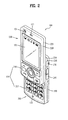
- FIG. 2 is a perspective view of a front side of a terminal according to an embodiment of the present invention.
- FIG. 3 is a rear view of the terminal shown in FIG. 2 ;
- FIG. 4 is a diagram of a vehicle navigation system having a display module for displaying an image of a road guide service
- FIG. 5 is a diagram of a vehicle navigation system fixed to a vehicle
- FIG. 6 is a diagram of a system including a terminal according to one embodiment of the present invention.
- FIG. 7 is a flowchart of a method of managing position information, which is implemented by a program according to one embodiment of the present invention.
- FIG. 8 is a diagram to explain a process for specifying a terminal having position information
- FIGs. 9A to 9F are diagrams of a screen on which images for obtaining new position information based on a plurality of position information according to one embodiment of the present invention are displayed;
- FIG. 10 is a diagram displaying route information of a route to a new destination from a location corresponding to each of a plurality of position information according to one embodiment of the present invention
- FIG. 11 is a diagram displaying route information of a route to a new destination from a location corresponding to each of a plurality of position information according to another embodiment of the present invention.
- FIG. 12 is a diagram of a screen showing transmitting obtained route information to a correspondent terminal and a process for changing a destination/route according to one embodiment of the present invention.
- FIG. 1 is a block diagram of terminal (or mobile terminal) 100 in accordance with an embodiment of the present invention.
- the terminal may be implemented using a variety of different types of terminals. Examples of such terminals include mobile phones, user equipment, smart phones, computers, digital broadcast terminals, personal digital assistants, portable multimedia players (PMP), and navigators. By way of non-limiting example only, further description will be with regard to a terminal. However, such teachings apply equally to other types of terminals.
- FIG. 1 shows the terminal 100 having various components, but it is understood that implementing all of the illustrated components is not a requirement. Greater or fewer components may alternatively be implemented.
- FIG. 1 shows a wireless communication unit 110 configured with several commonly implemented components.
- the wireless communication unit 110 typically includes one or more components which permits wireless communication between the terminal 100 and a wireless communication system or network within which the terminal is located.
- the broadcast receiving module 111 receives a broadcast signal and/or broadcast associated information from an external broadcast managing entity via a broadcast channel.
- the broadcast channel may include a satellite channel and a terrestrial channel.
- the broadcast managing entity refers generally to a system which transmits a broadcast signal and/or broadcast associated information.
- Examples of broadcast associated information include information associated with a broadcast channel, a broadcast program, a broadcast service provider, etc.
- broadcast associated information may include an electronic program guide (EPG) of digital multimedia broadcasting (DMB) and electronic service guide (ESG) of digital video broadcast-handheld (DVB-H).
- EPG electronic program guide
- DMB digital multimedia broadcasting
- ESG electronic service guide
- the broadcast signal may be implemented as a TV broadcast signal, a radio broadcast signal, and a data broadcast signal, among others. If desired, the broadcast signal may further include a broadcast signal combined with a TV or radio broadcast signal.
- the broadcast receiving module 111 may be configured to receive broadcast signals transmitted from various types of broadcast systems.
- broadcasting systems include digital multimedia broadcasting-terrestrial (DMB-T), digital multimedia broadcasting-satellite (DMB-S), digital video broadcast-handheld (DVB-H), the data broadcasting system known as media forward link only (MediaFLO®) and integrated services digital broadcast-terrestrial (ISDB-T).
- DMB-T digital multimedia broadcasting-terrestrial
- DMB-S digital multimedia broadcasting-satellite
- DVD-H digital video broadcast-handheld
- MediaFLO® media forward link only
- ISDB-T integrated services digital broadcast-terrestrial
- Receiving multicast signals is also possible.
- data received by the broadcast receiving module 111 may be stored in a suitable device, such as memory 160.
- the mobile communication module 112 transmits/receives wireless signals to/from one or more network entities (e.g., base station, Node-B). Such signals may represent audio, video, multimedia, control signaling, and data, among others.
- network entities e.g., base station, Node-B.
- the wireless Internet module 113 supports Internet access for the terminal. This module may be internally or externally coupled to the terminal 100.
- the short-range communication module 114 facilitates relatively short-range communications. Suitable technologies for implementing this module include radio frequency identification (RFID), infrared data association (IrDA), ultra-wideband (UWB), as well at the networking technologies commonly referred to as Bluetooth® and ZigBee®, to name a few.
- RFID radio frequency identification
- IrDA infrared data association
- UWB ultra-wideband
- Position-location module 115 identifies or otherwise obtains the location of the terminal 100. If desired, this module may be implemented using global positioning system (GPS) components which cooperate with associated satellites, network components, and combinations thereof.
- GPS global positioning system
- Audio/video (A/V) input unit 120 is configured to provide audio or video signal input to the terminal 100.
- the A/V input unit 120 includes a camera 121 and a microphone 122.
- the camera 121 receives and processes image frames of still pictures or video.
- the microphone 122 receives an external audio signal while the portable device is in a particular mode, such as phone call mode, recording mode and voice recognition. This audio signal is processed and converted into digital data.
- the portable device, and in particular A/V input unit 120 typically includes assorted noise removing algorithms to remove noise generated in the course of receiving the external audio signal. Data generated by the A/V input unit 120 may be stored in memory 160, utilized by output unit 150, or transmitted via one or more modules of communication unit 110. If desired, two or more microphones 122 and/or cameras 121 may be used.
- the user input unit 130 generates input data responsive to user manipulation of an associated input device or devices.
- Examples of such devices include a keypad, a dome switch, a touchpad (e.g., static pressure/capacitance), a jog wheel and a jog switch.
- a specific example is one in which the user input unit 130 is configured as a touchpad in cooperation with a touchscreen display (which will be described in more detail below).
- the sensing unit 140 provides status measurements of various aspects of the terminal. For instance, the sensing unit may detect an open/close status of the terminal, relative positioning of components (e.g., a display and keypad) of the terminal, a change of position of the terminal or a component of the terminal, a presence or absence of user contact with the terminal, orientation or acceleration/deceleration of the terminal. As an example, consider the terminal 100 being configured as a slide-type terminal. In this configuration, the sensing unit 140 may sense whether a sliding portion of the terminal is open or closed. Other examples include the sensing unit 140 sensing the presence or absence of power provided by the power supply 190, the presence or absence of a coupling or other connection between the interface unit 170 and an external device.
- components e.g., a display and keypad
- the interface unit 170 is often implemented to couple the terminal with external devices.
- Typical external devices include wired/wireless headphones, external chargers, power supplies, storage devices configured to store data (e.g., audio, video, pictures, etc.), earphones, and microphones, among others.
- the interface unit 170 may be configured using a wired/wireless data port, a card socket (e.g., for coupling to a memory card, subscriber identity module (SIM) card, user identity module (UIM) card, removable user identity module (RUIM) card), audio input/output ports and video input/output ports.
- SIM subscriber identity module
- UAM user identity module
- RUIM removable user identity module
- the output unit 150 generally includes various components which support the output requirements of the terminal 100.
- Display 151 is typically implemented to visually display information associated with the terminal 100. For instance, if the terminal 100 is operating in a phone call mode, the display 151 will generally provide a user interface or graphical user interface which includes information associated with placing, conducting, and terminating a phone call. As another example, if the terminal 100 is in a video call mode or a photographing mode, the display 151 may additionally or alternatively display images which are associated with these modes.
- One particular implementation includes the display 151 configured as a touch screen working in cooperation with an input device, such as a touchpad. This configuration permits the display to function both as an output device and an input device.
- the display 151 may be implemented using known display technologies including, for example, a liquid crystal display (LCD), a thin film transistor-liquid crystal display (TFT-LCD), an organic light-emitting diode display (OLED), a flexible display and a three-dimensional display.
- the terminal may include one or more of such displays.
- An example of a two-display embodiment is one in which one display is configured as an internal display (viewable when the terminal 100 is in an opened position) and a second display configured as an external display (viewable in both the open and closed positions).
- FIG. 1 further shows output unit 150 having an audio output module 152 which supports the audio output requirements of the terminal 100.
- the audio output module 152 is often implemented using one or more speakers, buzzers, other audio producing devices, and combinations thereof.
- the audio output module 152 functions in various modes including call-receiving mode, call-placing mode, recording mode, voice recognition mode and broadcast reception mode. During operation, the audio output module 152 outputs audio relating to a particular function (e.g., call received, message received, and errors).
- the output unit 150 is further shown having an alarm 153, which is commonly used to signal or otherwise identify the occurrence of a particular event associated with the terminal 100.
- Typical events include call received, message received and user input received.
- An example of such output includes the providing of tactile sensations (e.g., vibration) to a user.
- the alarm 153 may be configured to vibrate responsive to the terminal 100 receiving a call or message.
- vibration is provided by alarm 153 responsive to receiving user input at the terminal 100, thus providing a tactile feedback mechanism. It is understood that the various output provided by the components of output unit 150 may be separately performed, or such output may be performed using any combination of such components.
- the memory 160 is generally used to store various types of data to support the processing, control, and storage requirements of the terminal 100. Examples of such data include program instructions for applications operating on the terminal 100, contact data, phonebook data, messages, pictures, video, etc.
- the memory 160 shown in FIG. 1 may be implemented using any type (or combination) of suitable volatile and non-volatile memory or storage devices including random access memory (RAM), static random access memory (SRAM), electrically erasable programmable read-only memory (EEPROM), erasable programmable read-only memory (EPROM), programmable read-only memory (PROM), read-only memory (ROM), magnetic memory, flash memory, magnetic or optical disk, card-type memory, or other similar memory or data storage device.
- RAM random access memory
- SRAM static random access memory
- EEPROM electrically erasable programmable read-only memory
- EPROM erasable programmable read-only memory
- PROM programmable read-only memory
- ROM read-only memory
- magnetic memory flash memory, magnetic
- the controller 180 typically controls the overall operations of the terminal 100. For instance, the controller performs the control and processing associated with voice calls, data communications, video calls, camera operations and recording operations. If desired, the controller may include a multimedia module 181 which provides multimedia playback. The multimedia module 181 may be configured as part of the controller 180, or this module may be implemented as a separate component.
- the power supply 190 provides power required by the various components for the portable device.
- the provided power may be internal power, external power, or combinations thereof.
- Various embodiments described herein may be implemented in a computer-readable medium using, for example, computer software, hardware, or some combination thereof.
- the embodiments described herein may be implemented within one or more application specific integrated circuits (ASICs), digital signal processors (DSPs), digital signal processing devices (DSPDs), programmable logic devices (PLDs), field programmable gate arrays (FPGAs), processors, controllers, micro-oontrollers, microprocessors, other electronic units designed to perform the functions described herein, or a selective combination thereof.
- ASICs application specific integrated circuits
- DSPs digital signal processors
- DSPDs digital signal processing devices
- PLDs programmable logic devices
- FPGAs field programmable gate arrays
- processors controllers, micro-oontrollers, microprocessors, other electronic units designed to perform the functions described herein, or a selective combination thereof.
- controller 180 such embodiments are implemented by controller 180.
- the embodiments described herein may be implemented with separate software modules, such as procedures and functions, each of which perform one or more of the functions and operations described herein.
- the software codes can be implemented with a software application written in any suitable programming language and may be stored in memory (for example, memory 160), and executed by a controller or processor (for example, controller 180).
- Terminal 100 may be implemented in a variety of different configurations. Examples of such configurations include folder-type, slide-type, bar-type, rotational-type, swing-type and combinations thereof. For clarity, further disclosure will primarily relate to a slide-type terminal. However such teachings apply equally to other types of terminals.
- FIG. 2 is a perspective view of a front side of a terminal 100 according to an embodiment of the present invention.
- the terminal 100 is shown having a first body 200 configured to slideably cooperate with a second body 205.
- the user input unit 130 (described in FIG. 1 ) is implemented using function keys 210 and keypad 215.
- the function keys 210 are associated with first body 200
- the keypad 215 is associated with second body 205.
- the keypad 215 includes various keys (e.g., numbers, characters, and symbols) to enable a user to place a call, prepare a text or multimedia message, and otherwise operate the terminal.
- the first body 200 slides relative to second body 205 between open and closed positions. In a closed position, the first body 200 is positioned over the second body 205in such a manner that the keypad 215 is substantially or completely obscured by the first body 200. In the open position, user access to the keypad 215, as well as the display 151 and function keys 210, is possible.
- the function keys are convenient to a user for entering commands such as start, stop and scroll.
- the terminal 100 is operable in either a standby mode (e.g., able to receive a call or message, receive and respond to network control signaling), or an active call mode.
- a standby mode e.g., able to receive a call or message, receive and respond to network control signaling
- an active call mode e.g., the terminal 100 functions in a standby mode when in the closed position, and an active mode when in the open position. This mode configuration may be changed as required or desired.
- the first body 200 is shown formed from a first case 220 and a second case 225
- the second body 205 is shown formed from a first case 230 and a second case 235.
- the first and second cases are usually formed from a suitably ridge material such as injection molded plastic, or formed using metallic material such as stainless steel (STS) and titanium (Ti).
- one or more intermediate cases may be provided between the first 220, 230 and second cases 225, 235 of one or both of the first and second bodies 200, 205.
- the first and second bodies 200, 205 are typically sized to receive electronic components necessary to support operation of the terminal 100.
- the first body 200 is shown having a camera 121 and audio output unit 152, which is configured as a speaker, positioned relative to the display 151.
- the camera 121 may be constructed in such a manner that it can be selectively positioned (e.g., rotated, swiveled, etc.) relative to first body 200.
- the function keys 210 are positioned adjacent to a lower side of the display 151.
- the display 151 is shown implemented as an LCD or OLED. Recall that the display may also be configured as a touchscreen having an underlying touchpad which generates signals responsive to user contact (e.g., finger, stylus, etc.) with the touchscreen.
- Second body 205 is shown having a microphone 122 positioned adjacent to keypad 215, and side keys 245, which are one type of a user input unit 130, positioned along the side of second body 205.
- the side keys 245 may be configured as hot keys, such that the side keys are associated with a particular function of the terminal.
- An interface unit 170 is shown positioned adjacent to the side keys 245, and a power supply 190 in a form of a battery is located on a lower portion of the second body 205.
- FIG. 3 is a rear view of the terminal 100 shown in FIG. 2 .
- FIG. 3 shows the second body 205 having a camera 121, and an associated flash 250 and mirror 255.
- the flash 250 operates in conjunction with the camera 121 of the second body 205.
- the mirror 255 is useful for assisting a user to position camera 121 in a self-portrait mode.
- the camera 121 of the second body 205 faces a direction which is opposite to a direction faced by camera 121 of the first body 200 ( FIG. 2 ).
- Each of the cameras 121 of the first 200 and second 205 bodies may have the same or different capabilities.
- the camera 121 of the first body 200 operates with a relatively lower resolution than the camera of the second body 205.
- Such an arrangement works well during a video conference, for example, in which reverse link bandwidth capabilities may be limited.
- the relatively higher resolution of the camera 121 of the second body 205 ( FIG. 3 ) is useful for obtaining higher quality pictures for later use or for communicating to others.
- the second body 205 also includes an audio output module 152 configured as a speaker, and which is located on an upper side of the second body. If desired, the audio output modules 150 of the first and second bodies 200, 205, may cooperate to provide stereo output. Moreover, either or both of these audio output modules 150 may be configured to operate as a speakerphone.
- a broadcast signal receiving antenna 260 is shown located at an upper end of the second body 205.
- Antenna 260 functions in cooperation with the broadcast receiving module 111 ( FIG. 1 ). If desired, the antenna 260 may be fixed or configured to retract into the second body 205.
- the rear side of the first body 200 includes slide module 265, which slideably couples with a corresponding slide module located on the front side of the second body 205.
- first and second bodies 200, 205 may be modified as required or desired. In general, some or all of the components of one body may alternatively be implemented on the other body. In addition, the location and relative positioning of such components are not critical to many embodiments, and as such, the components may be positioned at locations which differ from those shown by the representative figures.
- the terminal 100 can be implemented in a vehicle navigation system, as shown in FIG. 4 and FIG. 5 , as well as the mobile phone shown in FIG. 2 or FIG. 3 .
- FIG. 4 shows a vehicle navigation system having a display module 151 for displaying a navigation route
- FIG. 5 shows a vehicle navigation system fixed within a vehicle.
- the vehicle navigation system shown in FIG. 4 and FIG. 5 can be detachably provided to a vehicle
- the mobile phone type terminal 100 shown in FIG. 2 or FIG. 3 can be detachably provided to a vehicle and is able to sufficiently perform a vehicle navigation function.
- the terminal 100 of FIGs. 1-5 may be configured to operate within a communication system which transmits data via frames or packets, including both wireless and wireline communication systems, and satellite-based communication systems. Such communication systems utilize different interfaces and/or physical layers.
- Examples of such interfaces utilized by the communication systems include example, frequency division multiple access (FDMA), time division multiple access (TDMA), code division multiple access (CDMA), and universal mobile telecommunications system (UMTS), the long term evolution (LTE) of the UMTS, and the global system for mobile communications (GSM).
- FDMA frequency division multiple access
- TDMA time division multiple access
- CDMA code division multiple access
- UMTS universal mobile telecommunications system
- LTE long term evolution
- GSM global system for mobile communications
- FIG. 6 is a diagram of a system including the terminal 100 according to one embodiment of the present invention, wherein the terminal receives position information from one or more satellites 610, 620 and 630 through the position-location module 115 ( Fig. 1 ).
- the terminal 100 is able to generate position information for providing a position based service using the received position information.
- the terminal 100 is able to transmit and receive position information and other information required for the position based service from an external terminal 640.
- FIG. 7 is a flowchart of a method of managing position information, which is implemented by a program according to one embodiment of the present invention.
- the terminal 100 receives its position information of a user terminal (equivalent to the former terminal 100) [S710].
- the terminal 100 activates the position-location module 115 and then receives position information of the user terminal 100 from at least one of the satellites 610, 620 and 630.
- terminal 100 receives position information from at least three satellites.
- the position information contains a latitude, longitude and altitude, speed information and time information.
- Terminal 100 is able to retrieve position information on an external terminal or place.
- a user provides at least one piece of identification information (e.g., phone number) of the external terminal 640 or a name of the specific place. If so, the terminal 100 is able to receive position information corresponding to at least one of the identification number and the name.
- identification information e.g., phone number
- the terminal 100 makes a request for an external terminal 640, or for an external server 650, to transmit position information of the external terminal 640 for which the identification number is provided.
- the terminal 100 is then able to receive the position information of the external terminal 640 from the external terminal 640 or the external server 650 correspondingly.
- the terminal 100 is able to store the position information of the specific place, in the memory 160 in advance, according to a name or number. In this case, the terminal 100 is able to periodically receive current position information of each terminal or location from the external server 650 and then store and update the memory.
- a process for specifying a terminal receiving position information in the receiving step [S710] is explained in detail with reference to FIG. 8 .
- the terminal 100 displays a map on which its position ('my position') is marked on a screen. If a user selects position tracking 812 for enabling a position tracking command of a specific place/terminal ( Fig. 8a ), the terminal 100 displays a window 811 for enabling an object to be tracked.
- the terminal 100 displays 'my position' 831 and Chul Soo's position 832 on a map.
- the terminal 100 stored a phone number of 'Chul Soo' in the memory 160 in advance.
- the position of Chul Soo's terminal means a position of a terminal having the phone number of 'Chul Soo' and 'my position' means a position of the terminal 100.
- the terminal 100 displays locations corresponding to 'my position' 831 and to 'exit #8 of Kangnam station' 861 on the map.
- the terminal 100 displays 'my position' 831, 'position of a terminal having a phone number 019-222-2222' 871 and 'position of a terminal corresponding to Young Hee' 872 on the map.
- the terminal 100 displays a straight line connecting 'my position' 831 and positions of Chul Soo 832, Exit 8 861, and terminals for phone number 019-222-2222 871 and Young Hee 872 thereby enabling a user to visually recognize straight-line distances between a plurality of tracked positions.
- the terminal 100 receives new position information [S720]. For instance, the terminal 100 is able to obtain or update new position information using at least one of traveling distances, traveling times, traveling speeds between the received position information. If a condition for obtaining new position information is provided by a user, the terminal 100 is able to obtain new position information corresponding to the provided condition. The terminal 100 is able to automatically determine new positions corresponding to the tracking targets.
- FIGS. 9A to 9F are diagrams of a screen images for obtaining new position information according to one embodiment of the present invention.
- the terminal 100 displays 'my position' 911 and Chul Soo's position 912 on a map based on position information of the terminal 100 and position information of Chul Soo [a].
- the terminal 100 displays a list 921 of data for obtaining new position information on the screen [b].
- the list 921 can contain data for obtaining new position information such as a traveling distance, a traveling time, a traveling speed, a direct input, a recommendation setting and the like.
- the terminal 100 is able to display a list 931 of location classifications for selecting a type of a place corresponding to position information [c]. For instance, if 'restaurant' 931-1 is selected from the place classifications, the new position information can be limited to restaurants. At least one of the place classifications is able to be selected.
- the terminal 100 obtains position information of 'destination 1' 941 located in the middle of a straight distance between 'my position' 911 and Chul Soo's position 912 as new position information, and displays 'destination 1' 941 on the map [d]. For instance, if the straight distance is '10km', a distance between 'my position' 911 and 'destination 1' 941 becomes 5km, and a distance between Chul Soo's position 912 and the location 941 becomes 5km as well.
- the terminal 100 obtains position information of 'destination 2' 951 located in the middle of an optimal route (e.g., route for a shortest necessary time) between 'my position' 911 and Chul Soo's position 912 as new position information, and then displays 'destination 2' 951 on the map. For instance, if the route distance is '14km', a distance between 'my position' 911 and 'destination 2' 951 becomes 7km and a distance between Chul Soo's position 912 and 'destination 2' 951 becomes 7km as well.
- an optimal route e.g., route for a shortest necessary time
- the terminal 100 obtains position information of 'destination 3' 961 having a same time from 'my position' 911 Chul Soo's position 912 on an optimal route (e.g., a route having a shortest necessary time) between 'my position' 911 and Chul Soo's position 912 and then displays 'destination 3' 961 on the map [f]. For instance, the terminal 100 is able to obtain the position information of the location having 30 minutes travel time from 'my position' 911 to the location 961 or from Chul Soo's position 912 to 'destination 3' 961.
- an optimal route e.g., a route having a shortest necessary time
- FIG. 9D Selecting a direct input 921-4 as a condition for obtaining new position information is explained with reference to FIG. 9D as follows. If 'exit #3 of Yangjae station' is provided by a user as new position information as illustrated in Fig 9D [g], the terminal 100 obtains position information of 'exit #3 of Yangjae station' and displays 'exit #3 of Yangjae station' 976 on the map.
- Selecting a direct input 921-4 as a condition for obtaining new position information is further explained with reference to FIG. 9E as follows. If '10 minutes from me, 30 minutes from a correspondent party' is provided as data for obtaining new position information by a user as illustrated in Fig. 9E [i], the terminal obtains position information of 'destination 4' 986 taken 10 minutes from 'my position' 911 and also taken 30 minutes from Chul Soo's position and then displays 'destination 4' on the map.
- a recommendation setting 921-5 is explained with reference to FIG. 9F as follows.
- the terminal 100 sets 'destination 5' 991 corresponding to new position information and then displays 'destination 5' 991 on the map Fig. 9F [k].
- the recommended location can include a noted place, a light traffic place, a place reached in a shortest time, or a place located in a shortest distance.
- the recommended location is set as a default by the terminal 100 or can be set according to a condition selected by a user.
- the locations 951, 961, 971, 976 and 986 shown in FIGs. 9B to 9F correspond to destinations of the terminal 100 or Chul Soo's destination.
- the terminal 100 obtains route information on new position information (S730).
- the route information can include a route from each of a plurality of the positions to the new position, a position and speed of the terminal 100 or of a correspondent terminal on the route, a travel time and distance to the new position information.
- the terminal 100 generates a route from my position 911 to 'destination 1' 941 in FIG. 9B , a route from another terminal (e.g., a route from Chul Soo's location 912), to 'destination 1' 941 in FIG. 9B , or the terminal 100 can be provided with the route information or route information of another terminal from the external server 650. Alternatively, the terminal 100 receives route information from the correspondent terminal and then obtains the route information corresponding to the correspondent terminal.
- a route from another terminal e.g., a route from Chul Soo's location 912
- the terminal 100 displays a route using the obtained route information [S740].
- the route means a service that provides route information from the terminal 100 to a location corresponding to new position information or route information from a correspondent terminal to a location corresponding to new position information.
- FIG. 10 is a diagram of a screen illustrating a route to 'destination 2' 941 from 'my position' 911 and Chul Soo's position 912 according to one embodiment of the present invention.
- the terminal 100 displays a current position of the terminal 100 on a route from 'my position' 911 to 'destination 2' and Chul-Soo's position 912 on a route with a start point at 'my position' 911 and an end point at 'destination 2' 941.
- the terminal 100 provides route information at a current position 1021 of the terminal 100 or Chul-Soo's terminal 1022 (e.g., a remaining distance and travel time to 'destination 2' 941, etc.) in detail.
- a current position 1021 of the terminal 100 or Chul-Soo's terminal 1022 e.g., a remaining distance and travel time to 'destination 2' 941, etc.
- a process for displaying a route to a new destination from a location corresponding to each of a plurality of locations according to the present invention is explained with reference to FIG. 11 as follows.
- FIG. 11 is a display screen displaying a route to 'destination 2' 941 from 'my position' 911 and Chul Soo's position 912 according to another embodiment of the present invention.
- the terminal 100 displays 'my position (location of the terminal 100) 911, a location 912 of Chul-Soo's terminal, and a location 941 corresponding to 'destination 2' on a map [a].
- terminal 100 transmits the new position information of 'destination 2' 941 via the wireless communication unit 110 and displays a window 1121 for indicating that the new position information is being transmitted [b].
- the terminal 100 provides a route based on route information of the terminal 100 while displaying the current position 1131 of the terminal 100 on a route from a start point at 'my position' 911 of the terminal 100 to 'destination 2' 941 [c].
- the terminal 100 displays a window 1141 for querying whether to check the route information received from the Chul-Soo terminal [d].
- the terminal 100 provides a route based on the route information of Chul-Soo's terminal by displaying Chul-Soo terminal current position 1151 on a route to 'destination 2' 941 from a start position at Chul Soo's position 912 [e].
- a process for transmitting route information to a correspondent terminal and a process for changing a destination or a route according to one embodiment of the present invention are explained with reference to FIG. 12 as follows.
- FIG. 12 displays transmitting obtained route information to a correspondent terminal and a process for changing a destination or a route according to one embodiment of the present invention.
- the terminal 100 provides a route while displaying a current position 911 of the terminal on a route for the terminal 100 and a current position 912 of Chul-Soo's terminal on a route for Chul-Soo's terminal [a].
- the terminal 100 displays a window 1221 querying whether to transmit the route information to Chul-Soo's terminal [b].
- the terminal 100 transmits the route information for the terminal 100 and or Chul-Soo's terminal to Chul-Soo's terminal and displays a window 1231 for indicating that the transmission is completed [c].
- the terminal 100 While the terminal 100 keeps providing the route information, if an estimated travel time to 'destination 2' 941 is delayed, the terminal 100 displays a window 1241 for enabling a user to select whether to change a destination or a route [d].
- the terminal 100 changes 'destination 2' 941 into 'destination 6' 1253 and then provides route information and a route based on the new location 1253 [e].
- the terminal 100 changes the present route to a new route and then provides information based on the changed route [f].
- the above-described position information managing method can be implemented in a program recorded medium as computer-readable codes.
- the computer-readable media include all kinds of recording devices in which data readable by a computer system are stored.
- the computer-readable media include ROM, RAM, CD-ROM, magnetic tapes, floppy discs, optical data storage devices, and the like for example and also include carrier-wave type implementations (e.g., transmission via Internet).
- the computer can include the controller 180 of the terminal 100.
- the present invention provides the following effects and advantages.
- the present invention obtains new position information using a plurality of position information, thereby enabling a user to set an appropriate destination without providing destinations one by one.
- the present invention obtains new position information using a plurality of position information, thereby setting an optimal position to a meeting place by considering a plurality of user positions.
Abstract
Description
- This application claims the benefit of the Korean Patent Application No.
10-2007-0083491 filed on August 20, 2007 - The present invention relates to a terminal and program recorded medium, and more particularly, to a terminal having a function for managing position information and a position information managing method recorded medium.
- A terminal is a device which may be configured to perform various functions. Examples of such functions include data and voice communications, capturing images and video via a camera, recording audio, playing music files via a speaker system, and displaying images and video on a display. Some terminals include additional functionality which supports game playing, while other terminals are configured as multimedia players. More recently, terminals have been configured to receive broadcast and multicast signals which permit viewing of content such as videos and television programs.
- Efforts are ongoing to support and increase the functionality of terminals. Such efforts include software and hardware improvements, as well as changes and improvements in the structural components which form the terminal.
- In particular, a terminal having a navigation system is capable of providing real-time map information in which a user-set route from an origin to a destination and a position of the terminal are contained.
- However, the related art terminal is too complicated for a user to input a necessary destination to a route setting by manipulating key buttons.
- Moreover, the related art fails to provide a method of setting a new location using information of a plurality of position locations.
- Accordingly, the present invention is directed to a terminal, method, and system that substantially obviate one or more problems due to limitations and disadvantages of the related art.
- An object of the present invention is to provide a terminal, method, and system by which new position information of remote terminals and locations can be obtained.
- Anther object of the present invention is to provide a terminal, method, and system by which information on travel routes from the locations of the remote terminals to a new location can be provided and displayed.
- Additional advantages, objects, and features of the invention will be set forth in part in the description which follows and in part will become apparent to those having ordinary skill in the art upon examination of the following or may be learned from practice of the invention. The objectives and other advantages of the invention may be realized and attained by the structure particularly pointed out in the written description and claims hereof as well as the appended drawings.
- To achieve these objects and other advantages and in accordance with the purpose of the invention, as embodied and broadly described herein, a terminal according to the present invention includes a wireless communication unit for receiving position information of the terminal, at least one remote terminal, and at least one destination. The terminal also includes a controller for determining route information between the terminal and the at least one destination, and between the at least one remote terminal and the at least one destination.
- In another aspect of the present invention, a method includes receiving position information of the terminal, at least one remote terminal, and at least one destination, and determining route information between the terminal and the at least one destination, and between the at least one remote terminal and the at least one destination. The method also includes displaying travel information between the terminal and the at least one destination, and between the at least one remote terminal and the at least one destination, wherein the travel information comprises at least one of distance, speed, estimated travel time, and direction of travel.
- The terminal also transmits the position information of the at least one destination to the at least one remote terminal and receives from the remote terminal the route information between the at least one remote terminal and the at least one destination. The terminal also transmits to the at least one remote terminal the route information between the terminal and the at least one destination.
- In another aspect of the present invention, a route information system includes a terminal for receiving position information of the terminal, at least one remote terminal, and at least one destination, and a server for transmitting position information of the terminal, the at least one remote terminal, and the at least one destination. The terminal transmits the position information of the at least one destination to the server and receives from the server the route information between the at least one remote terminal and the at least one destination, wherein the travel information comprises at least one of distance, speed, estimated travel time, and direction of travel.
- It is to be understood that both the foregoing general description and the following detailed description of the present invention are exemplary and explanatory and are intended to provide further explanation of the invention as claimed.
- The accompanying drawings, which are included to provide a further understanding of the invention and are incorporated in and constitute a part of this application, illustrate embodiment(s) of the invention and together with the description serve to explain the principle of the invention. In the drawings:
-
FIG. 1 is a block diagram of a terminal in accordance with an embodiment of the present invention; -
FIG. 2 is a perspective view of a front side of a terminal according to an embodiment of the present invention; -
FIG. 3 is a rear view of the terminal shown inFIG. 2 ; -
FIG. 4 is a diagram of a vehicle navigation system having a display module for displaying an image of a road guide service; and -
FIG. 5 is a diagram of a vehicle navigation system fixed to a vehicle; -
FIG. 6 is a diagram of a system including a terminal according to one embodiment of the present invention; -
FIG. 7 is a flowchart of a method of managing position information, which is implemented by a program according to one embodiment of the present invention; -
FIG. 8 is a diagram to explain a process for specifying a terminal having position information; -
FIGs. 9A to 9F are diagrams of a screen on which images for obtaining new position information based on a plurality of position information according to one embodiment of the present invention are displayed; -
FIG. 10 is a diagram displaying route information of a route to a new destination from a location corresponding to each of a plurality of position information according to one embodiment of the present invention; -
FIG. 11 is a diagram displaying route information of a route to a new destination from a location corresponding to each of a plurality of position information according to another embodiment of the present invention; and -
FIG. 12 is a diagram of a screen showing transmitting obtained route information to a correspondent terminal and a process for changing a destination/route according to one embodiment of the present invention. - Reference will now be made in detail to the preferred embodiments of the present invention, examples of which are illustrated in the accompanying drawings. It is to be understood by those of ordinary skill in this technological field that other embodiments may be utilized, and structural, electrical, as well as procedural changes may be made without departing from the scope of the present invention. Wherever possible, the same reference numbers will be used throughout the drawings to refer to the same or like parts.
-
FIG. 1 is a block diagram of terminal (or mobile terminal) 100 in accordance with an embodiment of the present invention. The terminal may be implemented using a variety of different types of terminals. Examples of such terminals include mobile phones, user equipment, smart phones, computers, digital broadcast terminals, personal digital assistants, portable multimedia players (PMP), and navigators. By way of non-limiting example only, further description will be with regard to a terminal. However, such teachings apply equally to other types of terminals.
FIG. 1 shows theterminal 100 having various components, but it is understood that implementing all of the illustrated components is not a requirement. Greater or fewer components may alternatively be implemented. -
FIG. 1 shows awireless communication unit 110 configured with several commonly implemented components. For instance, thewireless communication unit 110 typically includes one or more components which permits wireless communication between theterminal 100 and a wireless communication system or network within which the terminal is located. - The
broadcast receiving module 111 receives a broadcast signal and/or broadcast associated information from an external broadcast managing entity via a broadcast channel. The broadcast channel may include a satellite channel and a terrestrial channel. The broadcast managing entity refers generally to a system which transmits a broadcast signal and/or broadcast associated information. Examples of broadcast associated information include information associated with a broadcast channel, a broadcast program, a broadcast service provider, etc. For instance, broadcast associated information may include an electronic program guide (EPG) of digital multimedia broadcasting (DMB) and electronic service guide (ESG) of digital video broadcast-handheld (DVB-H). - The broadcast signal may be implemented as a TV broadcast signal, a radio broadcast signal, and a data broadcast signal, among others. If desired, the broadcast signal may further include a broadcast signal combined with a TV or radio broadcast signal.
- The
broadcast receiving module 111 may be configured to receive broadcast signals transmitted from various types of broadcast systems. By nonlimiting example, such broadcasting systems include digital multimedia broadcasting-terrestrial (DMB-T), digital multimedia broadcasting-satellite (DMB-S), digital video broadcast-handheld (DVB-H), the data broadcasting system known as media forward link only (MediaFLO®) and integrated services digital broadcast-terrestrial (ISDB-T). Receiving multicast signals is also possible. If desired, data received by thebroadcast receiving module 111 may be stored in a suitable device, such asmemory 160. - The
mobile communication module 112 transmits/receives wireless signals to/from one or more network entities (e.g., base station, Node-B). Such signals may represent audio, video, multimedia, control signaling, and data, among others. - The
wireless Internet module 113 supports Internet access for the terminal. This module may be internally or externally coupled to the terminal 100. - The short-
range communication module 114 facilitates relatively short-range communications. Suitable technologies for implementing this module include radio frequency identification (RFID), infrared data association (IrDA), ultra-wideband (UWB), as well at the networking technologies commonly referred to as Bluetooth® and ZigBee®, to name a few. - Position-
location module 115 identifies or otherwise obtains the location of the terminal 100. If desired, this module may be implemented using global positioning system (GPS) components which cooperate with associated satellites, network components, and combinations thereof. - Audio/video (A/V)
input unit 120 is configured to provide audio or video signal input to the terminal 100. As shown, the A/V input unit 120 includes acamera 121 and amicrophone 122. Thecamera 121 receives and processes image frames of still pictures or video. - The
microphone 122 receives an external audio signal while the portable device is in a particular mode, such as phone call mode, recording mode and voice recognition. This audio signal is processed and converted into digital data. The portable device, and in particular A/V input unit 120, typically includes assorted noise removing algorithms to remove noise generated in the course of receiving the external audio signal. Data generated by the A/V input unit 120 may be stored inmemory 160, utilized byoutput unit 150, or transmitted via one or more modules ofcommunication unit 110. If desired, two ormore microphones 122 and/orcameras 121 may be used. - The
user input unit 130 generates input data responsive to user manipulation of an associated input device or devices. Examples of such devices include a keypad, a dome switch, a touchpad (e.g., static pressure/capacitance), a jog wheel and a jog switch. A specific example is one in which theuser input unit 130 is configured as a touchpad in cooperation with a touchscreen display (which will be described in more detail below). - The
sensing unit 140 provides status measurements of various aspects of the terminal. For instance, the sensing unit may detect an open/close status of the terminal, relative positioning of components (e.g., a display and keypad) of the terminal, a change of position of the terminal or a component of the terminal, a presence or absence of user contact with the terminal, orientation or acceleration/deceleration of the terminal. As an example, consider the terminal 100 being configured as a slide-type terminal. In this configuration, thesensing unit 140 may sense whether a sliding portion of the terminal is open or closed. Other examples include thesensing unit 140 sensing the presence or absence of power provided by thepower supply 190, the presence or absence of a coupling or other connection between theinterface unit 170 and an external device. - The
interface unit 170 is often implemented to couple the terminal with external devices. Typical external devices include wired/wireless headphones, external chargers, power supplies, storage devices configured to store data (e.g., audio, video, pictures, etc.), earphones, and microphones, among others. Theinterface unit 170 may be configured using a wired/wireless data port, a card socket (e.g., for coupling to a memory card, subscriber identity module (SIM) card, user identity module (UIM) card, removable user identity module (RUIM) card), audio input/output ports and video input/output ports. - The
output unit 150 generally includes various components which support the output requirements of the terminal 100.Display 151 is typically implemented to visually display information associated with the terminal 100. For instance, if the terminal 100 is operating in a phone call mode, thedisplay 151 will generally provide a user interface or graphical user interface which includes information associated with placing, conducting, and terminating a phone call. As another example, if the terminal 100 is in a video call mode or a photographing mode, thedisplay 151 may additionally or alternatively display images which are associated with these modes. - One particular implementation includes the
display 151 configured as a touch screen working in cooperation with an input device, such as a touchpad. This configuration permits the display to function both as an output device and an input device. - The
display 151 may be implemented using known display technologies including, for example, a liquid crystal display (LCD), a thin film transistor-liquid crystal display (TFT-LCD), an organic light-emitting diode display (OLED), a flexible display and a three-dimensional display. The terminal may include one or more of such displays. An example of a two-display embodiment is one in which one display is configured as an internal display (viewable when the terminal 100 is in an opened position) and a second display configured as an external display (viewable in both the open and closed positions). -
FIG. 1 further showsoutput unit 150 having anaudio output module 152 which supports the audio output requirements of the terminal 100. Theaudio output module 152 is often implemented using one or more speakers, buzzers, other audio producing devices, and combinations thereof. Theaudio output module 152 functions in various modes including call-receiving mode, call-placing mode, recording mode, voice recognition mode and broadcast reception mode. During operation, theaudio output module 152 outputs audio relating to a particular function (e.g., call received, message received, and errors). - The
output unit 150 is further shown having analarm 153, which is commonly used to signal or otherwise identify the occurrence of a particular event associated with the terminal 100. Typical events include call received, message received and user input received. An example of such output includes the providing of tactile sensations (e.g., vibration) to a user. For instance, thealarm 153 may be configured to vibrate responsive to the terminal 100 receiving a call or message. As another example, vibration is provided byalarm 153 responsive to receiving user input at the terminal 100, thus providing a tactile feedback mechanism. It is understood that the various output provided by the components ofoutput unit 150 may be separately performed, or such output may be performed using any combination of such components. - The
memory 160 is generally used to store various types of data to support the processing, control, and storage requirements of the terminal 100. Examples of such data include program instructions for applications operating on the terminal 100, contact data, phonebook data, messages, pictures, video, etc. Thememory 160 shown inFIG. 1 may be implemented using any type (or combination) of suitable volatile and non-volatile memory or storage devices including random access memory (RAM), static random access memory (SRAM), electrically erasable programmable read-only memory (EEPROM), erasable programmable read-only memory (EPROM), programmable read-only memory (PROM), read-only memory (ROM), magnetic memory, flash memory, magnetic or optical disk, card-type memory, or other similar memory or data storage device. - The
controller 180 typically controls the overall operations of the terminal 100. For instance, the controller performs the control and processing associated with voice calls, data communications, video calls, camera operations and recording operations. If desired, the controller may include amultimedia module 181 which provides multimedia playback. Themultimedia module 181 may be configured as part of thecontroller 180, or this module may be implemented as a separate component. - The
power supply 190 provides power required by the various components for the portable device. The provided power may be internal power, external power, or combinations thereof. - Various embodiments described herein may be implemented in a computer-readable medium using, for example, computer software, hardware, or some combination thereof. For a hardware implementation, the embodiments described herein may be implemented within one or more application specific integrated circuits (ASICs), digital signal processors (DSPs), digital signal processing devices (DSPDs), programmable logic devices (PLDs), field programmable gate arrays (FPGAs), processors, controllers, micro-oontrollers, microprocessors, other electronic units designed to perform the functions described herein, or a selective combination thereof. In some cases, such embodiments are implemented by
controller 180. - For a software implementation, the embodiments described herein may be implemented with separate software modules, such as procedures and functions, each of which perform one or more of the functions and operations described herein. The software codes can be implemented with a software application written in any suitable programming language and may be stored in memory (for example, memory 160), and executed by a controller or processor (for example, controller 180).
-
Terminal 100 may be implemented in a variety of different configurations. Examples of such configurations include folder-type, slide-type, bar-type, rotational-type, swing-type and combinations thereof. For clarity, further disclosure will primarily relate to a slide-type terminal. However such teachings apply equally to other types of terminals. -
FIG. 2 is a perspective view of a front side of a terminal 100 according to an embodiment of the present invention. InFIG. 2 , the terminal 100 is shown having afirst body 200 configured to slideably cooperate with asecond body 205. The user input unit 130 (described inFIG. 1 ) is implemented usingfunction keys 210 andkeypad 215. Thefunction keys 210 are associated withfirst body 200, and thekeypad 215 is associated withsecond body 205. Thekeypad 215 includes various keys (e.g., numbers, characters, and symbols) to enable a user to place a call, prepare a text or multimedia message, and otherwise operate the terminal. - The
first body 200 slides relative tosecond body 205 between open and closed positions. In a closed position, thefirst body 200 is positioned over the second body 205in such a manner that thekeypad 215 is substantially or completely obscured by thefirst body 200. In the open position, user access to thekeypad 215, as well as thedisplay 151 andfunction keys 210, is possible. The function keys are convenient to a user for entering commands such as start, stop and scroll. - The terminal 100 is operable in either a standby mode (e.g., able to receive a call or message, receive and respond to network control signaling), or an active call mode. Typically, the terminal 100 functions in a standby mode when in the closed position, and an active mode when in the open position. This mode configuration may be changed as required or desired.
- The
first body 200 is shown formed from afirst case 220 and asecond case 225, and thesecond body 205 is shown formed from afirst case 230 and asecond case 235. The first and second cases are usually formed from a suitably ridge material such as injection molded plastic, or formed using metallic material such as stainless steel (STS) and titanium (Ti). - If desired, one or more intermediate cases may be provided between the first 220, 230 and
second cases second bodies second bodies - The
first body 200 is shown having acamera 121 andaudio output unit 152, which is configured as a speaker, positioned relative to thedisplay 151. If desired, thecamera 121 may be constructed in such a manner that it can be selectively positioned (e.g., rotated, swiveled, etc.) relative tofirst body 200. - The
function keys 210 are positioned adjacent to a lower side of thedisplay 151. Thedisplay 151 is shown implemented as an LCD or OLED. Recall that the display may also be configured as a touchscreen having an underlying touchpad which generates signals responsive to user contact (e.g., finger, stylus, etc.) with the touchscreen. -
Second body 205 is shown having amicrophone 122 positioned adjacent tokeypad 215, andside keys 245, which are one type of auser input unit 130, positioned along the side ofsecond body 205. Preferably, theside keys 245 may be configured as hot keys, such that the side keys are associated with a particular function of the terminal. Aninterface unit 170 is shown positioned adjacent to theside keys 245, and apower supply 190 in a form of a battery is located on a lower portion of thesecond body 205. -
FIG. 3 is a rear view of the terminal 100 shown inFIG. 2 .FIG. 3 shows thesecond body 205 having acamera 121, and an associatedflash 250 andmirror 255. Theflash 250 operates in conjunction with thecamera 121 of thesecond body 205. Themirror 255 is useful for assisting a user to positioncamera 121 in a self-portrait mode. Thecamera 121 of thesecond body 205 faces a direction which is opposite to a direction faced bycamera 121 of the first body 200 (FIG. 2 ). Each of thecameras 121 of the first 200 and second 205 bodies may have the same or different capabilities. - In an embodiment, the
camera 121 of thefirst body 200 operates with a relatively lower resolution than the camera of thesecond body 205. Such an arrangement works well during a video conference, for example, in which reverse link bandwidth capabilities may be limited. The relatively higher resolution of thecamera 121 of the second body 205 (FIG. 3 ) is useful for obtaining higher quality pictures for later use or for communicating to others. - The
second body 205 also includes anaudio output module 152 configured as a speaker, and which is located on an upper side of the second body. If desired, theaudio output modules 150 of the first andsecond bodies audio output modules 150 may be configured to operate as a speakerphone. - A broadcast
signal receiving antenna 260 is shown located at an upper end of thesecond body 205.Antenna 260 functions in cooperation with the broadcast receiving module 111 (FIG. 1 ). If desired, theantenna 260 may be fixed or configured to retract into thesecond body 205. The rear side of thefirst body 200 includesslide module 265, which slideably couples with a corresponding slide module located on the front side of thesecond body 205. - It is understood that the illustrated arrangement of the various components of the first and
second bodies - The terminal 100 according to the present invention can be implemented in a vehicle navigation system, as shown in
FIG. 4 andFIG. 5 , as well as the mobile phone shown inFIG. 2 orFIG. 3 . -
FIG. 4 shows a vehicle navigation system having adisplay module 151 for displaying a navigation route; andFIG. 5 shows a vehicle navigation system fixed within a vehicle. - It is understood that the vehicle navigation system shown in
FIG. 4 andFIG. 5 can be detachably provided to a vehicle, the mobilephone type terminal 100 shown inFIG. 2 orFIG. 3 can be detachably provided to a vehicle and is able to sufficiently perform a vehicle navigation function. - The
terminal 100 ofFIGs. 1-5 may be configured to operate within a communication system which transmits data via frames or packets, including both wireless and wireline communication systems, and satellite-based communication systems. Such communication systems utilize different interfaces and/or physical layers. - Examples of such interfaces utilized by the communication systems include example, frequency division multiple access (FDMA), time division multiple access (TDMA), code division multiple access (CDMA), and universal mobile telecommunications system (UMTS), the long term evolution (LTE) of the UMTS, and the global system for mobile communications (GSM). By way of non-limiting example only, further description will relate to a CDMA communication system, but such teachings apply equally to other system types.
- In the following description, a system including a terminal according to the present invention is explained with reference to
FIG. 6 . -
FIG. 6 is a diagram of a system including the terminal 100 according to one embodiment of the present invention, wherein the terminal receives position information from one ormore satellites Fig. 1 ). The terminal 100 is able to generate position information for providing a position based service using the received position information. - The terminal 100 is able to transmit and receive position information and other information required for the position based service from an
external terminal 640. - A method of managing position information according to the present invention is explained with reference to
FIG. 7. FIG. 7 is a flowchart of a method of managing position information, which is implemented by a program according to one embodiment of the present invention. The terminal 100 receives its position information of a user terminal (equivalent to the former terminal 100) [S710]. - If the terminal 100 enters a navigation mode, the terminal 100 activates the position-
location module 115 and then receives position information of theuser terminal 100 from at least one of thesatellites -
Terminal 100 is able to retrieve position information on an external terminal or place. - In this case, a user provides at least one piece of identification information (e.g., phone number) of the
external terminal 640 or a name of the specific place. If so, the terminal 100 is able to receive position information corresponding to at least one of the identification number and the name. - For example, in
FIG. 6 , the terminal 100 makes a request for anexternal terminal 640, or for anexternal server 650, to transmit position information of theexternal terminal 640 for which the identification number is provided. The terminal 100 is then able to receive the position information of theexternal terminal 640 from theexternal terminal 640 or theexternal server 650 correspondingly. - Moreover, the terminal 100 is able to store the position information of the specific place, in the
memory 160 in advance, according to a name or number. In this case, the terminal 100 is able to periodically receive current position information of each terminal or location from theexternal server 650 and then store and update the memory. - A process for specifying a terminal receiving position information in the receiving step [S710] is explained in detail with reference to
FIG. 8 . The terminal 100 displays a map on which its position ('my position') is marked on a screen. If a user selects position tracking 812 for enabling a position tracking command of a specific place/terminal (Fig. 8a ), the terminal 100 displays awindow 811 for enabling an object to be tracked. - Referring to (b) and (c) of
FIG. 8 , if 'Chul Soo' is a tracking target, the terminal 100 displays 'my position' 831 and Chul Soo'sposition 832 on a map. The terminal 100 stored a phone number of 'Chul Soo' in thememory 160 in advance. The position of Chul Soo's terminal means a position of a terminal having the phone number of 'Chul Soo' and 'my position' means a position of the terminal 100. - Referring to (d) and (e) of
FIG. 8 , if 'exit # 8 of Kangnam station' is a tracking target, the terminal 100 displays locations corresponding to 'my position' 831 and to 'exit # 8 of Kangnam station' 861 on the map. - Referring to (f) and (g) of
FIG. 8 , if '019-222-2222' and 'Young Hee' are position tracking targets, the terminal 100 displays 'my position' 831, 'position of a terminal having a phone number 019-222-2222' 871 and 'position of a terminal corresponding to Young Hee' 872 on the map. - In the above-explained states, (c), (e) and (g), the terminal 100 displays a straight line connecting 'my position' 831 and positions of
Chul Soo 832,Exit 8 861, and terminals for phone number 019-222-2222 871 andYoung Hee 872 thereby enabling a user to visually recognize straight-line distances between a plurality of tracked positions. - Referring now to
FIG. 7 , the terminal 100 receives new position information [S720]. For instance, the terminal 100 is able to obtain or update new position information using at least one of traveling distances, traveling times, traveling speeds between the received position information. If a condition for obtaining new position information is provided by a user, the terminal 100 is able to obtain new position information corresponding to the provided condition. The terminal 100 is able to automatically determine new positions corresponding to the tracking targets. - Obtaining new position information based on a plurality of position information according to the present invention is explained with reference to
FIGs. 9A to 9F as follows.FIGS. 9A to 9F are diagrams of a screen images for obtaining new position information according to one embodiment of the present invention. - Referring to
FIG. 9A , the terminal 100 displays 'my position' 911 and Chul Soo'sposition 912 on a map based on position information of the terminal 100 and position information of Chul Soo [a]. - If a
position setting area 913 for receiving a command for entering new position information setting mode is activated, the terminal 100 displays alist 921 of data for obtaining new position information on the screen [b]. In this case, thelist 921 can contain data for obtaining new position information such as a traveling distance, a traveling time, a traveling speed, a direct input, a recommendation setting and the like. - If the
position setting area 913 is activated again in the state [b], the terminal 100 is able to display alist 931 of location classifications for selecting a type of a place corresponding to position information [c]. For instance, if 'restaurant' 931-1 is selected from the place classifications, the new position information can be limited to restaurants. At least one of the place classifications is able to be selected. - Optionally, the process described in the state [c], which is not mandatory for the present invention, can be omitted if necessary.
- Selecting a traveling distance 921-1 to obtain new position information is explained with reference to
FIG. 9B as follows. The terminal 100 obtains position information of 'destination 1' 941 located in the middle of a straight distance between 'my position' 911 and Chul Soo'sposition 912 as new position information, and displays 'destination 1' 941 on the map [d]. For instance, if the straight distance is '10km', a distance between 'my position' 911 and 'destination 1' 941 becomes 5km, and a distance between Chul Soo'sposition 912 and thelocation 941 becomes 5km as well. - The terminal 100 obtains position information of 'destination 2' 951 located in the middle of an optimal route (e.g., route for a shortest necessary time) between 'my position' 911 and Chul Soo's
position 912 as new position information, and then displays 'destination 2' 951 on the map. For instance, if the route distance is '14km', a distance between 'my position' 911 and 'destination 2' 951 becomes 7km and a distance between Chul Soo'sposition 912 and 'destination 2' 951 becomes 7km as well. - Selecting a traveling time 921-2 as a condition for obtaining new position information is explained with reference to
FIG. 9C as follows. The terminal 100 obtains position information of 'destination 3' 961 having a same time from 'my position' 911 Chul Soo'sposition 912 on an optimal route (e.g., a route having a shortest necessary time) between 'my position' 911 and Chul Soo'sposition 912 and then displays 'destination 3' 961 on the map [f]. For instance, the terminal 100 is able to obtain the position information of the location having 30 minutes travel time from 'my position' 911 to thelocation 961 or from Chul Soo'sposition 912 to 'destination 3' 961. - Selecting a direct input 921-4 as a condition for obtaining new position information is explained with reference to
FIG. 9D as follows. If 'exit # 3 of Yangjae station' is provided by a user as new position information as illustrated inFig 9D [g], the terminal 100 obtains position information of 'exit # 3 of Yangjae station' and displays 'exit # 3 of Yangjae station' 976 on the map. - Selecting a direct input 921-4 as a condition for obtaining new position information is further explained with reference to
FIG. 9E as follows. If '10 minutes from me, 30 minutes from a correspondent party' is provided as data for obtaining new position information by a user as illustrated inFig. 9E [i], the terminal obtains position information of 'destination 4' 986 taken 10 minutes from 'my position' 911 and also taken 30 minutes from Chul Soo's position and then displays 'destination 4' on the map. - Selecting a recommendation setting 921-5 as a condition for obtaining new position information is explained with reference to
FIG. 9F as follows. The terminal 100 sets 'destination 5' 991 corresponding to new position information and then displays 'destination 5' 991 on the mapFig. 9F [k]. The recommended location can include a noted place, a light traffic place, a place reached in a shortest time, or a place located in a shortest distance. The recommended location is set as a default by the terminal 100 or can be set according to a condition selected by a user. - From the above description, it can be observed that the
locations FIGs. 9B to 9F correspond to destinations of the terminal 100 or Chul Soo's destination. - Referring again to
FIG. 7 , the terminal 100 obtains route information on new position information (S730). The route information can include a route from each of a plurality of the positions to the new position, a position and speed of the terminal 100 or of a correspondent terminal on the route, a travel time and distance to the new position information. - The terminal 100 generates a route from my
position 911 to 'destination 1' 941 inFIG. 9B , a route from another terminal (e.g., a route from Chul Soo's location 912), to 'destination 1' 941 inFIG. 9B , or the terminal 100 can be provided with the route information or route information of another terminal from theexternal server 650. Alternatively, the terminal 100 receives route information from the correspondent terminal and then obtains the route information corresponding to the correspondent terminal. - Subsequently, the terminal 100 displays a route using the obtained route information [S740]. In this case, the route means a service that provides route information from the terminal 100 to a location corresponding to new position information or route information from a correspondent terminal to a location corresponding to new position information.
- A process for displaying a route to a new destination from a location corresponding to each of a plurality of positions according to the present invention is explained with reference to
FIG. 10 as follows.FIG. 10 is a diagram of a screen illustrating a route to 'destination 2' 941 from 'my position' 911 and Chul Soo'sposition 912 according to one embodiment of the present invention. - The terminal 100 displays a current position of the terminal 100 on a route from 'my position' 911 to 'destination 2' and Chul-Soo's
position 912 on a route with a start point at 'my position' 911 and an end point at 'destination 2' 941. - If a
detailed view area 1014 is selected, the terminal 100 provides route information at acurrent position 1021 of the terminal 100 or Chul-Soo's terminal 1022 (e.g., a remaining distance and travel time to 'destination 2' 941, etc.) in detail. - A process for displaying a route to a new destination from a location corresponding to each of a plurality of locations according to the present invention is explained with reference to
FIG. 11 as follows. -
FIG. 11 is a display screen displaying a route to 'destination 2' 941 from 'my position' 911 and Chul Soo'sposition 912 according to another embodiment of the present invention. The terminal 100 displays 'my position (location of the terminal 100) 911, alocation 912 of Chul-Soo's terminal, and alocation 941 corresponding to 'destination 2' on a map [a]. - If a command for transmitting new position information to Chul-Soo's terminal is selected, terminal 100 transmits the new position information of 'destination 2' 941 via the
wireless communication unit 110 and displays awindow 1121 for indicating that the new position information is being transmitted [b]. - The terminal 100 provides a route based on route information of the terminal 100 while displaying the
current position 1131 of the terminal 100 on a route from a start point at 'my position' 911 of the terminal 100 to 'destination 2' 941 [c]. - If receiving route information from Chul-Soo's terminal in the state [c], the terminal 100 displays a
window 1141 for querying whether to check the route information received from the Chul-Soo terminal [d]. - If the route information has been received (Yes' 1141-1 is selected), the terminal 100 provides a route based on the route information of Chul-Soo's terminal by displaying Chul-Soo terminal
current position 1151 on a route to 'destination 2' 941 from a start position at Chul Soo's position 912 [e]. - A process for transmitting route information to a correspondent terminal and a process for changing a destination or a route according to one embodiment of the present invention are explained with reference to
FIG. 12 as follows. -
FIG. 12 displays transmitting obtained route information to a correspondent terminal and a process for changing a destination or a route according to one embodiment of the present invention. The terminal 100 provides a route while displaying acurrent position 911 of the terminal on a route for the terminal 100 and acurrent position 912 of Chul-Soo's terminal on a route for Chul-Soo's terminal [a]. - If a command for transmitting route information to the Chul-Soo terminal is activated [a], the terminal 100 displays a
window 1221 querying whether to transmit the route information to Chul-Soo's terminal [b]. - If 'Yes' 1221-1 is selected, the terminal 100 transmits the route information for the terminal 100 and or Chul-Soo's terminal to Chul-Soo's terminal and displays a
window 1231 for indicating that the transmission is completed [c]. - While the terminal 100 keeps providing the route information, if an estimated travel time to 'destination 2' 941 is delayed, the terminal 100 displays a
window 1241 for enabling a user to select whether to change a destination or a route [d]. - If 'destination change' 1241-1 is selected in state [d], the terminal 100 changes 'destination 2' 941 into 'destination 6' 1253 and then provides route information and a route based on the new location 1253 [e].
- If 'route change' 1241-2 is selected d], the terminal 100 changes the present route to a new route and then provides information based on the changed route [f].
- According to one embodiment of the present invention, the above-described position information managing method can be implemented in a program recorded medium as computer-readable codes. The computer-readable media include all kinds of recording devices in which data readable by a computer system are stored. The computer-readable media include ROM, RAM, CD-ROM, magnetic tapes, floppy discs, optical data storage devices, and the like for example and also include carrier-wave type implementations (e.g., transmission via Internet). The computer can include the
controller 180 of the terminal 100. - Accordingly, the present invention provides the following effects and advantages.
- First of all, the present invention obtains new position information using a plurality of position information, thereby enabling a user to set an appropriate destination without providing destinations one by one.
- Secondly, the present invention obtains new position information using a plurality of position information, thereby setting an optimal position to a meeting place by considering a plurality of user positions.
- It will be apparent to those skilled in the art that various modifications and variations can be made in the present invention without departing from the spirit or scope of the inventions. Thus, it is intended that the present invention covers the modifications and variations of this invention provided they come within the scope of the appended claims and their equivalents.
Claims (15)
- A terminal (100) comprising:a wireless communication unit (110) for receiving position information of the terminal, at least one remote terminal, and at least one destination; anda controller (180) for determining route information between the terminal and the at least one destination, and between the at least one remote terminal and the at least one destination.
- The terminal of claim 1, wherein the at least one remote terminal is identified by a name or a number.
- The terminal of any of claims 1 and 2, further comprising a display (151) for displaying travel information between the terminal and the at least one destination, and between the at least one remote terminal and the at least one destination.
- The terminal of claim 3, wherein the travel information comprises at least one of distance, speed, estimated travel time, and direction of travel.
- The terminal of claim 3, wherein the wireless communication unit transmits the position information of the at least one destination to the at least one remote terminal and receives from the remote terminal the route information between the at least one remote terminal and the at least one destination.
- The terminal of claim 3, wherein the wireless communication unit transmits to the at least one remote terminal the route information between the terminal and the at least one destination.
- A method of obtaining route information in a terminal, the method comprising:receiving position information of the terminal, at least one remote terminal, and at least one destination; anddetermining route information between the terminal and the at least one destination, and between the at least one remote terminal and the at least one destination.
- The method of claim 7, wherein the at least one remote terminal is identified by a name or a number.
- The method of claim 7, further comprising displaying travel information between the terminal and the at least one destination, and between the at least one remote terminal and the at least one destination.
- The method of claim 9, wherein the travel information comprises at least one of distance, speed, estimated travel time, and direction of travel.
- The method of claim 9, further comprising transmitting the position information of the at least one destination to the at least one remote terminal and receiving from the remote terminal the route information between the at least one remote terminal and the at least one destination.
- The method of claim 9, further comprising transmitting to the at least one remote terminal the route information between the terminal and the at least one destination.
- A route information system comprising:a terminal (100) for receiving position information of the terminal, at least one remote terminal, and at least one destination; anda server (650) for transmitting position information of the terminal, the at least one remote terminal, and the at least one destination.
- The system of claim 12, wherein the at least one remote terminal is identified by a name or a number.
- The system of claim 12, wherein the terminal unit further comprises a display (151) for displaying travel information between the terminal and the at least one destination, and between the at least one remote terminal and the at least one destination.
Applications Claiming Priority (1)
| Application Number | Priority Date | Filing Date | Title |
|---|---|---|---|
| KR1020070083491A KR101387504B1 (en) | 2007-08-20 | 2007-08-20 | Terminal having function for managing position information and program recording medium |
Publications (3)
| Publication Number | Publication Date |
|---|---|
| EP2028446A2 true EP2028446A2 (en) | 2009-02-25 |
| EP2028446A3 EP2028446A3 (en) | 2010-04-14 |
| EP2028446B1 EP2028446B1 (en) | 2015-03-18 |
Family
ID=40029185
Family Applications (1)
| Application Number | Title | Priority Date | Filing Date |
|---|---|---|---|
| EP08162700.2A Not-in-force EP2028446B1 (en) | 2007-08-20 | 2008-08-20 | Terminal and method for determining route information between the terminal, a destination and a further terminal |
Country Status (4)
| Country | Link |
|---|---|
| US (1) | US8346277B2 (en) |
| EP (1) | EP2028446B1 (en) |
| KR (1) | KR101387504B1 (en) |
| CN (1) | CN101373139B (en) |
Families Citing this family (14)
| Publication number | Priority date | Publication date | Assignee | Title |
|---|---|---|---|---|
| US20100323658A1 (en) * | 2009-06-17 | 2010-12-23 | Bethany Lagergren | Portable emergency response system to alert authorities of a medical issue during outdoor activities and related methods |
| TW201100848A (en) * | 2009-06-22 | 2011-01-01 | Htc Corp | Method of enhancing positioning measurement and related communication device |
| JP5444115B2 (en) * | 2010-05-14 | 2014-03-19 | 株式会社Nttドコモ | Data search apparatus, data search method and program |
| KR20120087233A (en) * | 2010-12-03 | 2012-08-07 | 한국전자통신연구원 | Method for tile-map service using image fusion, and system for the same |
| CN102546955A (en) * | 2012-02-10 | 2012-07-04 | 上海华勤通讯技术有限公司 | Emotion mobile terminal |
| US10006769B2 (en) | 2012-06-11 | 2018-06-26 | Samsung Electronics Co., Ltd. | Terminal apparatus, method and system for setting up destination and providing information |
| EP2675147B1 (en) | 2012-06-11 | 2022-03-23 | Samsung Electronics Co., Ltd. | Service providing system in a vehicle including display device and mobile device, and method for providing service using the same |
| US8996295B2 (en) * | 2012-09-11 | 2015-03-31 | GM Global Technology Operations LLC | Vehicle range projection |
| US8930122B2 (en) * | 2013-03-15 | 2015-01-06 | GM Global Technology Operations LLC | Methods and systems for associating vehicles en route to a common destination |
| WO2014183208A1 (en) * | 2013-05-17 | 2014-11-20 | Initiative Inc. | System for quickly finding the whereabouts of friends |
| US9291472B2 (en) * | 2014-06-02 | 2016-03-22 | Sap Se | Audible consumption of content while traveling to a destination |
| US11182870B2 (en) * | 2014-12-24 | 2021-11-23 | Mcafee, Llc | System and method for collective and collaborative navigation by a group of individuals |
| JP6122893B2 (en) * | 2015-03-19 | 2017-04-26 | ヤフー株式会社 | Navigation device, method and program |
| CN105159907B (en) * | 2015-06-18 | 2019-05-24 | 百度在线网络技术(北京)有限公司 | The transmission method and device of data |
Family Cites Families (13)
| Publication number | Priority date | Publication date | Assignee | Title |
|---|---|---|---|---|
| ES2156481B1 (en) * | 1998-03-03 | 2002-02-01 | Univ Valencia Politecnica | PROCEDURE FOR OBTAINING MODIFIED INORGANIC MOLECULAR SIZES AND ITS USE AS SEMIOCHEMICAL ISSUERS. |
| US6199010B1 (en) * | 1998-05-04 | 2001-03-06 | Lucent Technologies, Inc. | Wireless telecommunications system that provides navigational assistance to travelers |
| US6266615B1 (en) * | 1999-09-27 | 2001-07-24 | Televigation, Inc. | Method and system for an interactive and real-time distributed navigation system |
| US6424910B1 (en) * | 2000-11-22 | 2002-07-23 | Navigation Technologies Corp. | Method and system for providing related navigation features for two or more end users |
| US6577949B1 (en) * | 2000-11-22 | 2003-06-10 | Navigation Technologies Corp. | Method and system for exchanging routing data between end users |
| EP1282054A1 (en) * | 2001-08-01 | 2003-02-05 | Alcatel | Method for implementing an appointment service for participants of a communication network, and a service processor and program module for such |
| JP2003130655A (en) * | 2001-10-29 | 2003-05-08 | Matsushita Electric Ind Co Ltd | Navigation system |
| US9635540B2 (en) * | 2002-03-25 | 2017-04-25 | Jeffrey D. Mullen | Systems and methods for locating cellular phones and security measures for the same |
| JP4272073B2 (en) * | 2004-01-08 | 2009-06-03 | 株式会社デンソーアイティーラボラトリ | Method for determining meeting place using navigation device |
| DE602004009433T2 (en) | 2004-06-17 | 2008-03-20 | Alcatel Lucent | A method of providing a location-based service for organizing meetings |
| US7136747B2 (en) * | 2005-01-08 | 2006-11-14 | Stephen Raney | Method for GPS carpool rendezvous tracking and personal safety verification |
| US8712810B2 (en) * | 2006-12-29 | 2014-04-29 | Facebook, Inc. | Reserving a time block in a calendar application to account for a travel time between geographic locations of appointments |
| US7742774B2 (en) * | 2007-01-11 | 2010-06-22 | Virgin Mobile Usa, L.P. | Location-based text messaging |
-
2007
- 2007-08-20 KR KR1020070083491A patent/KR101387504B1/en active IP Right Grant
-
2008
- 2008-08-20 EP EP08162700.2A patent/EP2028446B1/en not_active Not-in-force
- 2008-08-20 CN CN2008102110532A patent/CN101373139B/en not_active Expired - Fee Related
- 2008-08-20 US US12/195,276 patent/US8346277B2/en not_active Expired - Fee Related
Non-Patent Citations (1)
| Title |
|---|
| None |
Also Published As
| Publication number | Publication date |
|---|---|
| KR101387504B1 (en) | 2014-04-21 |
| KR20090019225A (en) | 2009-02-25 |
| EP2028446B1 (en) | 2015-03-18 |
| CN101373139B (en) | 2013-05-01 |
| CN101373139A (en) | 2009-02-25 |
| EP2028446A3 (en) | 2010-04-14 |
| US20090054086A1 (en) | 2009-02-26 |
| US8346277B2 (en) | 2013-01-01 |
Similar Documents
| Publication | Publication Date | Title |
|---|---|---|
| EP2028446B1 (en) | Terminal and method for determining route information between the terminal, a destination and a further terminal | |
| US8849568B2 (en) | Portable terminal and method for providing network contents using a portable terminal | |
| US9088719B2 (en) | Mobile terminal for displaying an image in an image capture mode and method for controlling of the same | |
| US8433370B2 (en) | Mobile terminal and controlling method thereof | |
| US8452337B2 (en) | Navigation method and apparatus for mobile terminal | |
| US8751155B2 (en) | Mobile vehicle navigation method and apparatus thereof | |
| EP2028448B1 (en) | Terminal having function for managing position revelant information and program recorded medium | |
| US8301174B2 (en) | Mobile terminal and method for displaying location information therein | |
| EP3033837B1 (en) | Mobile terminal and method for controlling the same | |
| US10048833B2 (en) | Mobile terminal providing an improved memo function for various separate applications and method for controlling the same | |
| EP2073498B1 (en) | Communication device and method of selecting applications of communication device according to location information | |
| EP2124442A2 (en) | Mobile terminal and method of downloading content therein | |
| US20140211969A1 (en) | Mobile terminal and controlling method thereof | |
| US9584651B2 (en) | Mobile terminal and method for controlling the same | |
| US8483708B2 (en) | Mobile terminal and corresponding method for transmitting new position information to counterpart terminal | |
| EP2846523B1 (en) | Mobile terminal and controlling method thereof | |
| US20150084883A1 (en) | Mobile terminal and method for controlling the same | |
| KR101435835B1 (en) | Terminal and method of buffering channel therein | |
| KR100952248B1 (en) | Mobile terminal and its navigation method | |
| KR101474417B1 (en) | Display method for mobile terminal and apparatus thereof | |
| KR101504200B1 (en) | Mobile terminal having navigation and information displaying method therefor |
Legal Events
| Date | Code | Title | Description |
|---|---|---|---|
| PUAI | Public reference made under article 153(3) epc to a published international application that has entered the european phase |
Free format text: ORIGINAL CODE: 0009012 |
|
| 17P | Request for examination filed |
Effective date: 20080820 |
|
| AK | Designated contracting states |
Kind code of ref document: A2 Designated state(s): AT BE BG CH CY CZ DE DK EE ES FI FR GB GR HR HU IE IS IT LI LT LU LV MC MT NL NO PL PT RO SE SI SK TR |
|
| AX | Request for extension of the european patent |
Extension state: AL BA MK RS |
|
| PUAL | Search report despatched |
Free format text: ORIGINAL CODE: 0009013 |
|
| AK | Designated contracting states |
Kind code of ref document: A3 Designated state(s): AT BE BG CH CY CZ DE DK EE ES FI FR GB GR HR HU IE IS IT LI LT LU LV MC MT NL NO PL PT RO SE SI SK TR |
|
| AX | Request for extension of the european patent |
Extension state: AL BA MK RS |
|
| 17Q | First examination report despatched |
Effective date: 20111027 |
|
| GRAP | Despatch of communication of intention to grant a patent |
Free format text: ORIGINAL CODE: EPIDOSNIGR1 |
|
| AKX | Designation fees paid |
Designated state(s): AT BE BG CH CY CZ DE DK EE ES FI FR GB GR HR HU IE IS IT LI LT LU LV MC MT NL NO PL PT RO SE SI SK TR |
|
| INTG | Intention to grant announced |
Effective date: 20141028 |
|
| GRAS | Grant fee paid |
Free format text: ORIGINAL CODE: EPIDOSNIGR3 |
|
| GRAA | (expected) grant |
Free format text: ORIGINAL CODE: 0009210 |
|
| AK | Designated contracting states |
Kind code of ref document: B1 Designated state(s): AT BE BG CH CY CZ DE DK EE ES FI FR GB GR HR HU IE IS IT LI LT LU LV MC MT NL NO PL PT RO SE SI SK TR |
|
| REG | Reference to a national code |
Ref country code: GB Ref legal event code: FG4D |
|
| REG | Reference to a national code |
Ref country code: CH Ref legal event code: EP |
|
| REG | Reference to a national code |
Ref country code: IE Ref legal event code: FG4D |
|
| REG | Reference to a national code |
Ref country code: AT Ref legal event code: REF Ref document number: 716861 Country of ref document: AT Kind code of ref document: T Effective date: 20150415 |
|
| REG | Reference to a national code |
Ref country code: DE Ref legal event code: R096 Ref document number: 602008037174 Country of ref document: DE Effective date: 20150430 |
|
| REG | Reference to a national code |
Ref country code: FR Ref legal event code: PLFP Year of fee payment: 8 |
|
| REG | Reference to a national code |
Ref country code: NL Ref legal event code: VDEP Effective date: 20150318 |
|
| REG | Reference to a national code |
Ref country code: NL Ref legal event code: VDEP Effective date: 20150318 |
|
| PG25 | Lapsed in a contracting state [announced via postgrant information from national office to epo] |
Ref country code: SE Free format text: LAPSE BECAUSE OF FAILURE TO SUBMIT A TRANSLATION OF THE DESCRIPTION OR TO PAY THE FEE WITHIN THE PRESCRIBED TIME-LIMIT Effective date: 20150318 Ref country code: FI Free format text: LAPSE BECAUSE OF FAILURE TO SUBMIT A TRANSLATION OF THE DESCRIPTION OR TO PAY THE FEE WITHIN THE PRESCRIBED TIME-LIMIT Effective date: 20150318 Ref country code: LT Free format text: LAPSE BECAUSE OF FAILURE TO SUBMIT A TRANSLATION OF THE DESCRIPTION OR TO PAY THE FEE WITHIN THE PRESCRIBED TIME-LIMIT Effective date: 20150318 Ref country code: NO Free format text: LAPSE BECAUSE OF FAILURE TO SUBMIT A TRANSLATION OF THE DESCRIPTION OR TO PAY THE FEE WITHIN THE PRESCRIBED TIME-LIMIT Effective date: 20150618 Ref country code: HR Free format text: LAPSE BECAUSE OF FAILURE TO SUBMIT A TRANSLATION OF THE DESCRIPTION OR TO PAY THE FEE WITHIN THE PRESCRIBED TIME-LIMIT Effective date: 20150318 |
|
| REG | Reference to a national code |
Ref country code: AT Ref legal event code: MK05 Ref document number: 716861 Country of ref document: AT Kind code of ref document: T Effective date: 20150318 |
|
| REG | Reference to a national code |
Ref country code: LT Ref legal event code: MG4D |
|
| PG25 | Lapsed in a contracting state [announced via postgrant information from national office to epo] |
Ref country code: GR Free format text: LAPSE BECAUSE OF FAILURE TO SUBMIT A TRANSLATION OF THE DESCRIPTION OR TO PAY THE FEE WITHIN THE PRESCRIBED TIME-LIMIT Effective date: 20150619 Ref country code: LV Free format text: LAPSE BECAUSE OF FAILURE TO SUBMIT A TRANSLATION OF THE DESCRIPTION OR TO PAY THE FEE WITHIN THE PRESCRIBED TIME-LIMIT Effective date: 20150318 |
|
| PG25 | Lapsed in a contracting state [announced via postgrant information from national office to epo] |
Ref country code: NL Free format text: LAPSE BECAUSE OF FAILURE TO SUBMIT A TRANSLATION OF THE DESCRIPTION OR TO PAY THE FEE WITHIN THE PRESCRIBED TIME-LIMIT Effective date: 20150318 |
|
| PG25 | Lapsed in a contracting state [announced via postgrant information from national office to epo] |
Ref country code: PT Free format text: LAPSE BECAUSE OF FAILURE TO SUBMIT A TRANSLATION OF THE DESCRIPTION OR TO PAY THE FEE WITHIN THE PRESCRIBED TIME-LIMIT Effective date: 20150720 Ref country code: SK Free format text: LAPSE BECAUSE OF FAILURE TO SUBMIT A TRANSLATION OF THE DESCRIPTION OR TO PAY THE FEE WITHIN THE PRESCRIBED TIME-LIMIT Effective date: 20150318 Ref country code: RO Free format text: LAPSE BECAUSE OF FAILURE TO SUBMIT A TRANSLATION OF THE DESCRIPTION OR TO PAY THE FEE WITHIN THE PRESCRIBED TIME-LIMIT Effective date: 20150318 Ref country code: ES Free format text: LAPSE BECAUSE OF FAILURE TO SUBMIT A TRANSLATION OF THE DESCRIPTION OR TO PAY THE FEE WITHIN THE PRESCRIBED TIME-LIMIT Effective date: 20150318 Ref country code: EE Free format text: LAPSE BECAUSE OF FAILURE TO SUBMIT A TRANSLATION OF THE DESCRIPTION OR TO PAY THE FEE WITHIN THE PRESCRIBED TIME-LIMIT Effective date: 20150318 Ref country code: CZ Free format text: LAPSE BECAUSE OF FAILURE TO SUBMIT A TRANSLATION OF THE DESCRIPTION OR TO PAY THE FEE WITHIN THE PRESCRIBED TIME-LIMIT Effective date: 20150318 |
|
| PG25 | Lapsed in a contracting state [announced via postgrant information from national office to epo] |
Ref country code: IS Free format text: LAPSE BECAUSE OF FAILURE TO SUBMIT A TRANSLATION OF THE DESCRIPTION OR TO PAY THE FEE WITHIN THE PRESCRIBED TIME-LIMIT Effective date: 20150718 Ref country code: AT Free format text: LAPSE BECAUSE OF FAILURE TO SUBMIT A TRANSLATION OF THE DESCRIPTION OR TO PAY THE FEE WITHIN THE PRESCRIBED TIME-LIMIT Effective date: 20150318 Ref country code: PL Free format text: LAPSE BECAUSE OF FAILURE TO SUBMIT A TRANSLATION OF THE DESCRIPTION OR TO PAY THE FEE WITHIN THE PRESCRIBED TIME-LIMIT Effective date: 20150318 |
|
| REG | Reference to a national code |
Ref country code: DE Ref legal event code: R097 Ref document number: 602008037174 Country of ref document: DE |
|
| PG25 | Lapsed in a contracting state [announced via postgrant information from national office to epo] |
Ref country code: IT Free format text: LAPSE BECAUSE OF FAILURE TO SUBMIT A TRANSLATION OF THE DESCRIPTION OR TO PAY THE FEE WITHIN THE PRESCRIBED TIME-LIMIT Effective date: 20150318 |
|
| PLBE | No opposition filed within time limit |
Free format text: ORIGINAL CODE: 0009261 |
|
| STAA | Information on the status of an ep patent application or granted ep patent |
Free format text: STATUS: NO OPPOSITION FILED WITHIN TIME LIMIT |
|
| PG25 | Lapsed in a contracting state [announced via postgrant information from national office to epo] |
Ref country code: DK Free format text: LAPSE BECAUSE OF FAILURE TO SUBMIT A TRANSLATION OF THE DESCRIPTION OR TO PAY THE FEE WITHIN THE PRESCRIBED TIME-LIMIT Effective date: 20150318 |
|
| 26N | No opposition filed |
Effective date: 20151221 |
|
| PG25 | Lapsed in a contracting state [announced via postgrant information from national office to epo] |
Ref country code: SI Free format text: LAPSE BECAUSE OF FAILURE TO SUBMIT A TRANSLATION OF THE DESCRIPTION OR TO PAY THE FEE WITHIN THE PRESCRIBED TIME-LIMIT Effective date: 20150318 |
|
| PG25 | Lapsed in a contracting state [announced via postgrant information from national office to epo] |
Ref country code: LU Free format text: LAPSE BECAUSE OF FAILURE TO SUBMIT A TRANSLATION OF THE DESCRIPTION OR TO PAY THE FEE WITHIN THE PRESCRIBED TIME-LIMIT Effective date: 20150820 Ref country code: MC Free format text: LAPSE BECAUSE OF FAILURE TO SUBMIT A TRANSLATION OF THE DESCRIPTION OR TO PAY THE FEE WITHIN THE PRESCRIBED TIME-LIMIT Effective date: 20150318 |
|
| REG | Reference to a national code |
Ref country code: CH Ref legal event code: PL |
|
| PG25 | Lapsed in a contracting state [announced via postgrant information from national office to epo] |
Ref country code: CH Free format text: LAPSE BECAUSE OF NON-PAYMENT OF DUE FEES Effective date: 20150831 Ref country code: LI Free format text: LAPSE BECAUSE OF NON-PAYMENT OF DUE FEES Effective date: 20150831 |
|
| REG | Reference to a national code |
Ref country code: IE Ref legal event code: MM4A |
|
| REG | Reference to a national code |
Ref country code: FR Ref legal event code: PLFP Year of fee payment: 9 |
|
| PG25 | Lapsed in a contracting state [announced via postgrant information from national office to epo] |
Ref country code: IE Free format text: LAPSE BECAUSE OF NON-PAYMENT OF DUE FEES Effective date: 20150820 |
|
| PG25 | Lapsed in a contracting state [announced via postgrant information from national office to epo] |
Ref country code: BE Free format text: LAPSE BECAUSE OF FAILURE TO SUBMIT A TRANSLATION OF THE DESCRIPTION OR TO PAY THE FEE WITHIN THE PRESCRIBED TIME-LIMIT Effective date: 20150318 |
|
| PG25 | Lapsed in a contracting state [announced via postgrant information from national office to epo] |
Ref country code: MT Free format text: LAPSE BECAUSE OF FAILURE TO SUBMIT A TRANSLATION OF THE DESCRIPTION OR TO PAY THE FEE WITHIN THE PRESCRIBED TIME-LIMIT Effective date: 20150318 |
|
| PG25 | Lapsed in a contracting state [announced via postgrant information from national office to epo] |
Ref country code: HU Free format text: LAPSE BECAUSE OF FAILURE TO SUBMIT A TRANSLATION OF THE DESCRIPTION OR TO PAY THE FEE WITHIN THE PRESCRIBED TIME-LIMIT; INVALID AB INITIO Effective date: 20080820 Ref country code: BG Free format text: LAPSE BECAUSE OF FAILURE TO SUBMIT A TRANSLATION OF THE DESCRIPTION OR TO PAY THE FEE WITHIN THE PRESCRIBED TIME-LIMIT Effective date: 20150318 |
|
| PG25 | Lapsed in a contracting state [announced via postgrant information from national office to epo] |
Ref country code: CY Free format text: LAPSE BECAUSE OF FAILURE TO SUBMIT A TRANSLATION OF THE DESCRIPTION OR TO PAY THE FEE WITHIN THE PRESCRIBED TIME-LIMIT Effective date: 20150318 |
|
| REG | Reference to a national code |
Ref country code: FR Ref legal event code: PLFP Year of fee payment: 10 |
|
| PG25 | Lapsed in a contracting state [announced via postgrant information from national office to epo] |
Ref country code: TR Free format text: LAPSE BECAUSE OF FAILURE TO SUBMIT A TRANSLATION OF THE DESCRIPTION OR TO PAY THE FEE WITHIN THE PRESCRIBED TIME-LIMIT Effective date: 20150318 |
|
| REG | Reference to a national code |
Ref country code: FR Ref legal event code: PLFP Year of fee payment: 11 |
|
| PGFP | Annual fee paid to national office [announced via postgrant information from national office to epo] |
Ref country code: DE Payment date: 20180705 Year of fee payment: 11 Ref country code: FR Payment date: 20180710 Year of fee payment: 11 |
|
| PGFP | Annual fee paid to national office [announced via postgrant information from national office to epo] |
Ref country code: GB Payment date: 20180706 Year of fee payment: 11 |
|
| REG | Reference to a national code |
Ref country code: DE Ref legal event code: R119 Ref document number: 602008037174 Country of ref document: DE |
|
| GBPC | Gb: european patent ceased through non-payment of renewal fee |
Effective date: 20190820 |
|
| PG25 | Lapsed in a contracting state [announced via postgrant information from national office to epo] |
Ref country code: DE Free format text: LAPSE BECAUSE OF NON-PAYMENT OF DUE FEES Effective date: 20200303 Ref country code: FR Free format text: LAPSE BECAUSE OF NON-PAYMENT OF DUE FEES Effective date: 20190831 |
|
| PG25 | Lapsed in a contracting state [announced via postgrant information from national office to epo] |
Ref country code: GB Free format text: LAPSE BECAUSE OF NON-PAYMENT OF DUE FEES Effective date: 20190820 |