EP2033593B1 - "Microprocessor controlled delivery system for cardiac valve prosthesis" - Google Patents
"Microprocessor controlled delivery system for cardiac valve prosthesis" Download PDFInfo
- Publication number
- EP2033593B1 EP2033593B1 EP08163752A EP08163752A EP2033593B1 EP 2033593 B1 EP2033593 B1 EP 2033593B1 EP 08163752 A EP08163752 A EP 08163752A EP 08163752 A EP08163752 A EP 08163752A EP 2033593 B1 EP2033593 B1 EP 2033593B1
- Authority
- EP
- European Patent Office
- Prior art keywords
- prosthesis
- valve
- microprocessor
- sensor
- deployment
- Prior art date
- Legal status (The legal status is an assumption and is not a legal conclusion. Google has not performed a legal analysis and makes no representation as to the accuracy of the status listed.)
- Active
Links
- 210000003709 heart valve Anatomy 0.000 title claims description 36
- 238000003384 imaging method Methods 0.000 claims description 25
- 230000007246 mechanism Effects 0.000 claims description 13
- 239000008280 blood Substances 0.000 claims description 10
- 210000004369 blood Anatomy 0.000 claims description 10
- 238000004891 communication Methods 0.000 claims description 7
- OYPRJOBELJOOCE-UHFFFAOYSA-N Calcium Chemical compound [Ca] OYPRJOBELJOOCE-UHFFFAOYSA-N 0.000 claims description 2
- 229910052791 calcium Inorganic materials 0.000 claims description 2
- 239000011575 calcium Substances 0.000 claims description 2
- 230000000747 cardiac effect Effects 0.000 claims description 2
- 238000012014 optical coherence tomography Methods 0.000 claims description 2
- 238000002496 oximetry Methods 0.000 claims description 2
- 230000005855 radiation Effects 0.000 claims 1
- 238000000034 method Methods 0.000 description 40
- 238000002513 implantation Methods 0.000 description 34
- 210000001765 aortic valve Anatomy 0.000 description 14
- 230000015572 biosynthetic process Effects 0.000 description 13
- 238000005755 formation reaction Methods 0.000 description 13
- 230000033001 locomotion Effects 0.000 description 12
- 238000013459 approach Methods 0.000 description 8
- 210000002435 tendon Anatomy 0.000 description 8
- 238000004873 anchoring Methods 0.000 description 5
- 239000000463 material Substances 0.000 description 5
- 238000012986 modification Methods 0.000 description 5
- 230000004048 modification Effects 0.000 description 5
- 210000005166 vasculature Anatomy 0.000 description 5
- 210000000709 aorta Anatomy 0.000 description 4
- 230000017531 blood circulation Effects 0.000 description 4
- 210000005240 left ventricle Anatomy 0.000 description 4
- 230000008569 process Effects 0.000 description 4
- 230000009471 action Effects 0.000 description 3
- 210000005242 cardiac chamber Anatomy 0.000 description 3
- 238000006073 displacement reaction Methods 0.000 description 3
- 230000000694 effects Effects 0.000 description 3
- 239000012530 fluid Substances 0.000 description 3
- 230000006870 function Effects 0.000 description 3
- 239000007943 implant Substances 0.000 description 3
- 238000011065 in-situ storage Methods 0.000 description 3
- 238000002595 magnetic resonance imaging Methods 0.000 description 3
- 230000036961 partial effect Effects 0.000 description 3
- 210000002376 aorta thoracic Anatomy 0.000 description 2
- 230000008901 benefit Effects 0.000 description 2
- 238000001804 debridement Methods 0.000 description 2
- 239000003814 drug Substances 0.000 description 2
- 239000000243 solution Substances 0.000 description 2
- 210000000115 thoracic cavity Anatomy 0.000 description 2
- 230000000007 visual effect Effects 0.000 description 2
- 206010002091 Anaesthesia Diseases 0.000 description 1
- 206010016275 Fear Diseases 0.000 description 1
- HTTJABKRGRZYRN-UHFFFAOYSA-N Heparin Chemical compound OC1C(NC(=O)C)C(O)OC(COS(O)(=O)=O)C1OC1C(OS(O)(=O)=O)C(O)C(OC2C(C(OS(O)(=O)=O)C(OC3C(C(O)C(O)C(O3)C(O)=O)OS(O)(=O)=O)C(CO)O2)NS(O)(=O)=O)C(C(O)=O)O1 HTTJABKRGRZYRN-UHFFFAOYSA-N 0.000 description 1
- 229920006362 Teflon® Polymers 0.000 description 1
- 238000007792 addition Methods 0.000 description 1
- 230000037005 anaesthesia Effects 0.000 description 1
- 210000003484 anatomy Anatomy 0.000 description 1
- 230000001174 ascending effect Effects 0.000 description 1
- 238000010009 beating Methods 0.000 description 1
- 230000005540 biological transmission Effects 0.000 description 1
- 239000002775 capsule Substances 0.000 description 1
- 230000004087 circulation Effects 0.000 description 1
- 239000011248 coating agent Substances 0.000 description 1
- 238000000576 coating method Methods 0.000 description 1
- 230000000295 complement effect Effects 0.000 description 1
- 230000006835 compression Effects 0.000 description 1
- 238000007906 compression Methods 0.000 description 1
- 239000000470 constituent Substances 0.000 description 1
- 238000010276 construction Methods 0.000 description 1
- 230000008602 contraction Effects 0.000 description 1
- 230000007423 decrease Effects 0.000 description 1
- 238000010586 diagram Methods 0.000 description 1
- 238000002224 dissection Methods 0.000 description 1
- 210000001105 femoral artery Anatomy 0.000 description 1
- 230000000004 hemodynamic effect Effects 0.000 description 1
- 229960002897 heparin Drugs 0.000 description 1
- 229920000669 heparin Polymers 0.000 description 1
- 230000001976 improved effect Effects 0.000 description 1
- 230000006872 improvement Effects 0.000 description 1
- 238000010348 incorporation Methods 0.000 description 1
- 230000001939 inductive effect Effects 0.000 description 1
- 230000000977 initiatory effect Effects 0.000 description 1
- 238000002347 injection Methods 0.000 description 1
- 239000007924 injection Substances 0.000 description 1
- 230000009191 jumping Effects 0.000 description 1
- 230000000670 limiting effect Effects 0.000 description 1
- 238000002406 microsurgery Methods 0.000 description 1
- 238000012544 monitoring process Methods 0.000 description 1
- HLXZNVUGXRDIFK-UHFFFAOYSA-N nickel titanium Chemical compound [Ti].[Ti].[Ti].[Ti].[Ti].[Ti].[Ti].[Ti].[Ti].[Ti].[Ti].[Ni].[Ni].[Ni].[Ni].[Ni].[Ni].[Ni].[Ni].[Ni].[Ni].[Ni].[Ni].[Ni].[Ni] HLXZNVUGXRDIFK-UHFFFAOYSA-N 0.000 description 1
- 229910001000 nickel titanium Inorganic materials 0.000 description 1
- 239000004810 polytetrafluoroethylene Substances 0.000 description 1
- 229920001343 polytetrafluoroethylene Polymers 0.000 description 1
- 230000008092 positive effect Effects 0.000 description 1
- 230000001681 protective effect Effects 0.000 description 1
- 210000003102 pulmonary valve Anatomy 0.000 description 1
- 238000005086 pumping Methods 0.000 description 1
- 238000011084 recovery Methods 0.000 description 1
- 230000000717 retained effect Effects 0.000 description 1
- 230000002441 reversible effect Effects 0.000 description 1
- 210000003291 sinus of valsalva Anatomy 0.000 description 1
- 230000002966 stenotic effect Effects 0.000 description 1
- 238000006467 substitution reaction Methods 0.000 description 1
- 238000001356 surgical procedure Methods 0.000 description 1
- 229940126585 therapeutic drug Drugs 0.000 description 1
- MEYZYGMYMLNUHJ-UHFFFAOYSA-N tunicamycin Natural products CC(C)CCCCCCCCCC=CC(=O)NC1C(O)C(O)C(CC(O)C2OC(C(O)C2O)N3C=CC(=O)NC3=O)OC1OC4OC(CO)C(O)C(O)C4NC(=O)C MEYZYGMYMLNUHJ-UHFFFAOYSA-N 0.000 description 1
- 238000011144 upstream manufacturing Methods 0.000 description 1
- 230000002861 ventricular Effects 0.000 description 1
Images


Classifications
-
- A—HUMAN NECESSITIES
- A61—MEDICAL OR VETERINARY SCIENCE; HYGIENE
- A61F—FILTERS IMPLANTABLE INTO BLOOD VESSELS; PROSTHESES; DEVICES PROVIDING PATENCY TO, OR PREVENTING COLLAPSING OF, TUBULAR STRUCTURES OF THE BODY, e.g. STENTS; ORTHOPAEDIC, NURSING OR CONTRACEPTIVE DEVICES; FOMENTATION; TREATMENT OR PROTECTION OF EYES OR EARS; BANDAGES, DRESSINGS OR ABSORBENT PADS; FIRST-AID KITS
- A61F2/00—Filters implantable into blood vessels; Prostheses, i.e. artificial substitutes or replacements for parts of the body; Appliances for connecting them with the body; Devices providing patency to, or preventing collapsing of, tubular structures of the body, e.g. stents
- A61F2/02—Prostheses implantable into the body
- A61F2/24—Heart valves ; Vascular valves, e.g. venous valves; Heart implants, e.g. passive devices for improving the function of the native valve or the heart muscle; Transmyocardial revascularisation [TMR] devices; Valves implantable in the body
- A61F2/2427—Devices for manipulating or deploying heart valves during implantation
- A61F2/2436—Deployment by retracting a sheath
-
- A—HUMAN NECESSITIES
- A61—MEDICAL OR VETERINARY SCIENCE; HYGIENE
- A61F—FILTERS IMPLANTABLE INTO BLOOD VESSELS; PROSTHESES; DEVICES PROVIDING PATENCY TO, OR PREVENTING COLLAPSING OF, TUBULAR STRUCTURES OF THE BODY, e.g. STENTS; ORTHOPAEDIC, NURSING OR CONTRACEPTIVE DEVICES; FOMENTATION; TREATMENT OR PROTECTION OF EYES OR EARS; BANDAGES, DRESSINGS OR ABSORBENT PADS; FIRST-AID KITS
- A61F2/00—Filters implantable into blood vessels; Prostheses, i.e. artificial substitutes or replacements for parts of the body; Appliances for connecting them with the body; Devices providing patency to, or preventing collapsing of, tubular structures of the body, e.g. stents
- A61F2/02—Prostheses implantable into the body
- A61F2/24—Heart valves ; Vascular valves, e.g. venous valves; Heart implants, e.g. passive devices for improving the function of the native valve or the heart muscle; Transmyocardial revascularisation [TMR] devices; Valves implantable in the body
- A61F2/2427—Devices for manipulating or deploying heart valves during implantation
- A61F2/243—Deployment by mechanical expansion
- A61F2/2433—Deployment by mechanical expansion using balloon catheter
-
- A—HUMAN NECESSITIES
- A61—MEDICAL OR VETERINARY SCIENCE; HYGIENE
- A61B—DIAGNOSIS; SURGERY; IDENTIFICATION
- A61B5/00—Measuring for diagnostic purposes; Identification of persons
- A61B5/02—Detecting, measuring or recording pulse, heart rate, blood pressure or blood flow; Combined pulse/heart-rate/blood pressure determination; Evaluating a cardiovascular condition not otherwise provided for, e.g. using combinations of techniques provided for in this group with electrocardiography or electroauscultation; Heart catheters for measuring blood pressure
- A61B5/021—Measuring pressure in heart or blood vessels
-
- A—HUMAN NECESSITIES
- A61—MEDICAL OR VETERINARY SCIENCE; HYGIENE
- A61B—DIAGNOSIS; SURGERY; IDENTIFICATION
- A61B5/00—Measuring for diagnostic purposes; Identification of persons
- A61B5/02—Detecting, measuring or recording pulse, heart rate, blood pressure or blood flow; Combined pulse/heart-rate/blood pressure determination; Evaluating a cardiovascular condition not otherwise provided for, e.g. using combinations of techniques provided for in this group with electrocardiography or electroauscultation; Heart catheters for measuring blood pressure
- A61B5/024—Detecting, measuring or recording pulse rate or heart rate
-
- A—HUMAN NECESSITIES
- A61—MEDICAL OR VETERINARY SCIENCE; HYGIENE
- A61B—DIAGNOSIS; SURGERY; IDENTIFICATION
- A61B5/00—Measuring for diagnostic purposes; Identification of persons
- A61B5/02—Detecting, measuring or recording pulse, heart rate, blood pressure or blood flow; Combined pulse/heart-rate/blood pressure determination; Evaluating a cardiovascular condition not otherwise provided for, e.g. using combinations of techniques provided for in this group with electrocardiography or electroauscultation; Heart catheters for measuring blood pressure
- A61B5/026—Measuring blood flow
-
- A—HUMAN NECESSITIES
- A61—MEDICAL OR VETERINARY SCIENCE; HYGIENE
- A61F—FILTERS IMPLANTABLE INTO BLOOD VESSELS; PROSTHESES; DEVICES PROVIDING PATENCY TO, OR PREVENTING COLLAPSING OF, TUBULAR STRUCTURES OF THE BODY, e.g. STENTS; ORTHOPAEDIC, NURSING OR CONTRACEPTIVE DEVICES; FOMENTATION; TREATMENT OR PROTECTION OF EYES OR EARS; BANDAGES, DRESSINGS OR ABSORBENT PADS; FIRST-AID KITS
- A61F2/00—Filters implantable into blood vessels; Prostheses, i.e. artificial substitutes or replacements for parts of the body; Appliances for connecting them with the body; Devices providing patency to, or preventing collapsing of, tubular structures of the body, e.g. stents
- A61F2/02—Prostheses implantable into the body
- A61F2/24—Heart valves ; Vascular valves, e.g. venous valves; Heart implants, e.g. passive devices for improving the function of the native valve or the heart muscle; Transmyocardial revascularisation [TMR] devices; Valves implantable in the body
- A61F2/2412—Heart valves ; Vascular valves, e.g. venous valves; Heart implants, e.g. passive devices for improving the function of the native valve or the heart muscle; Transmyocardial revascularisation [TMR] devices; Valves implantable in the body with soft flexible valve members, e.g. tissue valves shaped like natural valves
- A61F2/2418—Scaffolds therefor, e.g. support stents
Definitions
- the present invention relates to instruments for the in situ delivery and positioning of implantable devices.
- the invention relates to the in situ delivery of expandable prosthetic cardiac valves using a microprocessor controlled delivery system.
- valves designed to be implanted using minimally-invasive surgical techniques or endovascular delivery are used as an alternative to traditional cardiac valve prostheses.
- Implantation of a percutaneous valve is a far less invasive act than the surgical operation required for implanting traditional cardiac valve prostheses.
- expandable prosthetic valves typically include an anchoring structure or armature, which is able to support and fix the valve prosthesis in the implantation position, and prosthetic valve elements, generally in the form of leaflets or flaps, which are stably connected to the anchoring structure and are able to regulate blood flow.
- an anchoring structure or armature which is able to support and fix the valve prosthesis in the implantation position
- prosthetic valve elements generally in the form of leaflets or flaps, which are stably connected to the anchoring structure and are able to regulate blood flow.
- One exemplary expandable prosthetic valve is disclosed in U.S. Publication 2006/0178740 A1 .
- An advantage of these expandable prosthetic heart valves is that they enable implantation using various minimally invasive or sutureless techniques.
- One non-limiting exemplary application for such an expandable valve prosthesis is for aortic valve replacement.
- Various techniques are generally known for implanting such an aortic valve prosthesis and include percutaneous implantation (e.g., transvascular delivery through a catheter), dissection of the ascending aorta using minimally invasive thoracic access (e.g., mini-thoracotomy), and transapical delivery wherein the aortic valve annulus is accessed directly through an opening near the apex of the left ventricle.
- percutaneous and thoracic access approaches involve delivering the prosthesis in a direction opposing blood flow (i.e., retrograde), whereas the transapical approach involves delivering the prosthesis in the same direction as blood flow (i.e., antegrade)
- Similar techniques may also be applied to implant such a cardiac valve prosthesis at other locations (e.g., a pulmonary valve annulus).
- the invention reletes to a devices according to the preamble of claim 1, which is known e.g. from WO 2005/065200 A .
- the present invention having the features set forth in claim 1 according to one embodiment, is a device for implanting an expandable heart valve prosthesis, the device comprising a deploying mechanism capable of deploying the prosthesis and a microprocessor communicatively linked with at least a portion of the deploying mechanism.
- the present invention is a device for implanting a heart valve prosthesis, the device comprising a microprocessor and at least one functionality controlled by the microprocessor.
- An example of an improved method of delivering an implantable heart valve prosthesis is also disclosed.
- the improvement comprising superimposing real-time images taken from an imaging mechanism onto pre-operatively taken three-dimensional images and positioning the prosthesis as a function of its location in relation to the images.
- FIGS 1A and 1B illustrate, in general terms, a delivery instrument according to two exemplary embodiments of the present invention.
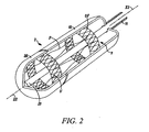
- Figure 2 is a partial cutaway, perspective view of a distal portion of the instrument of Figure 1 , according to one embodiment of the present invention.
- Figures 3A-3E illustrate a sequence of deploying a prosthetic heart valve using a retrograde approach, according to one embodiment of the present invention.
- Figures 4A-4E illustrate a sequence of deploying a prosthetic heart valve using an antegrade approach, according to another embodiment of the present invention.
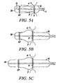
- Figures 5A-5C illustrate a sequence of deploying a prosthetic heart valve, according to yet another embodiment of the present invention.
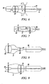
- FIGS 6-9 illustrates further possible features of the instrument illustrated herein, according to various embodiments of the present invention.
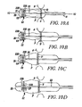
- Figure 10A-10D illustrate a sequence of deploying a prosthetic heart valve, according to another embodiment of the present invention.
- Figure 11 is a schematic diagram of a control system for controlling deployment of a prosthetic heart valve.
- FIGS 1a and 1b show an instrument 1 for implanting and radially deploying in situ an expandable, prosthetic cardiac valve.
- the prosthetic cardiac valve could be of the type described in U.S. Publication 2006/0178740 A1 .
- the instrument 1 could be used to deliver a variety of prosthetic cardiac valves and is not limited to any particular prosthetic valve structure.
- the instrument 1 includes a carrier portion 2 for enclosing and carrying the prosthetic device and a manipulation portion 3 that couples the carrier portion 2 to a control handle 4 where two actuator members (for instance two sliders 5, 6) are located.
- the manipulation portion 3 may assume various configurations.
- Figure 1A shows a configuration where the portion 3 is comprised of a substantially rigid bar with a length (e.g., 10 cm) that will permit positioning of the carrier portion 2, and the prosthetic cardiac valve carried thereby, at an aortic valve site.
- This configuration is adapted for use, for example, in the sutureless and the transapical implantation methods.
- Figure 1B conversely, shows a second configuration, where the portion 3 is essentially comprised of an elongated, flexible catheter-like member that allows positioning of the carrier portion 3, and the prosthetic cardiac valve carried thereby, at an aortic valve site via transvascular catheterization (e.g., initiating at the femoral artery).
- the flexible, catheter-like member is braided or otherwise adapted to facilitate transmission of torque from the handle 4 to the carrier portion 2, such that the operator may effect radial positioning of the carrier portion 2 during the implantation procedure.
- the instrument 1 is adapted for use with a separate delivery tool.
- the instrument 1, for example, may be sized and shaped for delivery through a lumen of a tube or trocar during a "sutureless" or transapical delivery technique.
- the instrument 1 may be adapted for delivery through a working lumen of a delivery or guide catheter.
- the operator may first deliver a guide catheter through the patient's vasculature to the implant site and then advance the instrument 1 through the lumen.
- other techniques known in the art are used to reach the implantation site from a location outside the patient's body.
- the carrier portion 2 includes two deployment elements 10, 20, each independently operable to allow the expansion of at least one corresponding, radially expandable portion of the implant device.
- the cardiac valve prosthesis indicated as a whole as V, which is disclosed in U.S. Publication 2006/0178740 A1
- two such radially expandable portions are provided situated respectively at the inflow end IF and the outflow end OF for the pulsated blood flow through the prosthesis.
- the cardiac valve prosthesis may include more than two expandable members and, likewise, the carrier portion 2 may include more than two independent deployment elements.
- the valve prosthesis may be self-expanding (e.g., made from a superelastic material such as Nitinol) or may require expansion by another device (e.g., balloon expansion).
- FIG. 2 illustrates an embodiment for use with a self-expanding cardiac valve prosthesis.
- the cardiac valve prosthesis V is arranged within the carrier portion 2, such that an expandable portion IF and an expandable portion OF are each located within one of the deployment elements 10, 20.
- Each deployment element 10, 20 may be formed as a collar, cap or sheath.
- Each deployment element 10, 20 is able to constrain the portions IF, OF in a radially contracted position, against the elastic strength of its constituent material.
- the portions IF, OF are able to radially expand, as a result of their characteristics of superelasticity, only when released from the deployment element 10, 20.
- the release of the portions IF, OF is obtained by causing an axial movement of the deployment elements 10, 20 along the main axis X2 of the carrier portion 2.
- the operator e.g., physician
- causes this axial movement by manipulating the sliders 5 and 6, which are coupled to the deployment elements 10, 20.
- expansion of the radially expandable portions IF, OF is caused by a positive expansion action exerted by the deployment elements 10, 20.
- the deployment elements 10, 20 are comprised of expandable balloons onto which the portions IF, OF are coupled (e.g., "crimped") in a radially contracted position.
- the operator causes radial expansion of the portions IF, OF by causing expansion of the balloons, using any of a variety of techniques known in the art.
- Figures 3-5 illustrate exemplary deployment techniques for the embodiment wherein the expandable portions IF, OF are made of a self-expandable material.
- the armature of the prosthetic cardiac valve prosthesis V is schematically shown (i.e., the valve leaflets are not shown).
- the armature includes the expandable entry (inflow) portion IF and the expandable exit (outflow) portion OF, which are connected axially by anchoring formations P.
- the formations P are spaced at 120° intervals about the armature circumference and are configured to radially protrude from the prosthesis V so as to penetrate into the sinuses of Valsalva.
- the inflow end IF of the prosthesis V is located in correspondence with the aortic annulus, thereby facing the left ventricle.
- the profile of the aortic annulus is shown schematically by the dashed lines A in Figures 3-5 .
- the outflow end OF is located in the ascending line of the aorta, in a position immediately distal to the sinuses of Valsalva, wherein the formations P extend.
- Figures 3-5 show a carrier portion 2 having two deployment elements 10, 20 each of which is capable of "encapsulating" a respective one of the inflow IF and outflow OF portions, to constrain the portions IF, OF from radially expanding.
- Both of the elements 10, 20 can be arranged to slide longitudinally with respect to the principal axis X2 of the carrier portion 2. The axial movement of the elements 10, 20 is obtained, according to exemplary embodiments, via the sliders 5, 6 provided on the handle 4 at the proximal end of the manipulation portion 3 of the instrument 1.
- the slider 5 may act on the deployment element 20 through a respective control wire or tendon 21, while the slider 6 may act on the deployment element 10 through a tubular control sheath 11 slidably arranged over the tendon 21, with both the elements 11, 21 slidable along the axis X2.
- an internal surface of the elements 11, 21 comprise a low-friction or lubricious material, such as an ultra-high molecular weight material or PTFE (e.g., Teflon®).
- a low-friction or lubricious material such as an ultra-high molecular weight material or PTFE (e.g., Teflon®).
- PTFE ultra-high molecular weight material
- Such a coating will enable the elements 11, 21 to move or slide with respect to the portions IF, OF, such that the portions IF, OF are released upon axial movement of the elements 11, 21.
- the sheath 11 is movable in a distal-to-proximal direction, so that the sheath and thus the element 10 move or slide "backwards" with respect to the carrier portion 2.
- the sliding movement of the tendon 21 will take place in a proximal-to-distal direction, so that the tendon and thus the element 20 move or slide "forwards" with respect to the carrier portion 2.
- movement of the elements 10, 20 is obtained by manipulating rigid actuation members from the handle 4.
- Figures 3-5 are deliberately simplified for clarity of representation and do not take into in account, for instance, the fact that the portion 3 of the instrument may include other control tendons/sheaths and/or ducts for inflating the post-expansion balloons (see Figure 6 ). Also, the element 20 could be actuated by means of a sheath rather than a tendon. Also, whatever their specific form of embodiment, the actuator members 11, 21 of the deployment elements 10, 20 may also have associated locking means (not shown, but of a known type) to prevent undesired actuation of the deployment elements 10, 20.
- the deployment elements 10, 20 are actuatable entirely independently of each other. This gives the operator complete freedom in selecting which of the portions IF, OF to deploy first according to the specific implantation method or conditions.
- Figures 3A-3E illustrate use of the instrument 1 for a "retrograde” approach (e.g., in the case of sutureless or percutaneous implantation), to the valve annulus, wherein the cardiac valve prosthesis V approaches the valve annulus from the aortic arch.
- FIG 3A (as in the following Figures 4A and 5A ), the cardiac valve prosthesis V is shown mounted in or carried by the carrier portion 2 of the instrument 1, such that the deployment elements 10, 20 constrain the annular ends IF, OF of the prosthesis V in a radially contracted position.
- Figure 3B shows the element 10 retracted axially with respect to the axis X2 of the carrier portion 2 a sufficient distance to uncover and release the formations P, which are then able to expand (e.g., due to their superelastic construction) such that they protrude beyond the diameter of the elements 10, 20.
- the formations P are allowed to expand, while the remaining portions of the prosthesis V are maintained in a radially contracted configuration.
- the operator can take the necessary action for ensuring the appropriate positioning of the prosthesis V in correspondence with the sinuses of Valsalva SV.
- the profile of the sinuses of Valsalva are shown schematically in Figure 3B by the dashed lines SV.
- Such appropriate positioning includes both axial positioning (i.e. avoiding deploying the prosthetic valve V too far "upstream” or too far “downstream” of the desired position with the ensuing negative effect that the inflow end IF is not correctly positioned with respect to the valve annulus A) and radial positioning.
- the sinuses of Valsalva are configured as a hollow, three-lobed structure. Accordingly, accurately positioning each formation P of the prosthesis V in a respective sinus of Valsalva will ensure the correct positioning or angular orientation of the prosthetic valve as a whole, which will ensure that the leaflets of the prosthetic valve are correctly oriented (i.e., extend at the angular positions of the annulus where the natural valve leaflets were located before removal).
- the instrument 1 may further include various structures or features to assist the operator in obtaining the appropriate axial positioning with respect to the aortic annulus and radial positioning with respect to the sinuses of Valsalva.
- the instrument 1 (or the guide catheter or delivery tube), for example may include a lumen sufficient to allow the injection of contrast fluid to a location at the implantation site.
- this lumen would have an opening located past the inflow end IF or the prosthesis V, such that any injected contrast fluid would then flow back toward the prosthesis V, thereby enabling the operator to obtain a visual image of the implantation site, including an image of the sinuses of Valsalva.
- the prosthesis V may include radiopaque markers disposed at appropriate locations to assist in this positioning.
- the carrier portion 2 and the prosthesis V may be arranged from the beginning in the configuration represented in Figure 3B , namely with the formations P already protruding radially with respect to the profile of the prosthesis, while the annular end portions IF, OF are constrained in a radially contracted position by the elements 10, 20.
- the element 10 will have a sufficient length only to cover the axial extension of the annular end portion OF, as it need not radially constraint the formations P.
- Figure 3C shows the element 20 displaced distally with respect to the prosthesis V by the tendon 21.
- the element 20 was displaced a length sufficient to uncover the annular inflow portion IF, such that the portion IF is able to expand radially to assume the desired anchoring position at the valve annulus A.
- This release of the inflow portion IF takes place while the prosthetic valve V is still precisely retained and controlled by the instrument 1, such that it will not move or "jump" with respect to the valve annulus during the expansion of the portion IF.
- the prosthetic implantation process progresses by sliding the deployment element 10 so that it releases the outflow annular portion OF.
- the portion OF can then radially expand against the aortic wall, thus completing the second phase of the implantation operation of the prosthesis V.
- the carrier portion 2 and the instrument 1 as a whole can be withdrawn with respect to the implantation site through the center of the prosthesis V.
- the carrier portion 2 is withdrawn after the deployment elements 10, 20 have been brought back to their initial positions, that is after having caused the elements 10, 20 to slide, in a proximal-to-distal and in a distal-to-proximal direction, respectively.
- the sequence of operations represented in Figures 3A-3E may be accomplished with a pulsating heart and without interrupting the natural circulation of blood.
- FIGS 4A-4E show an implantation procedure of a prosthesis V, according to another embodiment of the present invention. This procedure is similar to the procedure shown in Figures 3A-3E , but Figures 4A-4E show an "antegrade" approach, typical of a transapical implantation procedure.
- the prosthesis V mounted in the carrier portion 2 is advanced to the implantation site (e.g., aortic valve) through the left ventricle.
- the implantation site e.g., aortic valve
- the same criteria and principles will also apply to different valve types (e.g. mitral).
- Various techniques for accessing the aortic valve site through the left ventricle are known in the art.
- One exemplary technique for transapical delivery is disclosed in U.S. Publication 2005/0240200 .
- Figures 4A-4E are substantially identical to Figures 3A-3E , except that the position assumed by the prosthetic valve V is inverted. Accordingly, in the case of the intervention of "antegrade" type of Figures 4A-4E , the carrier portion 2 of the instrument 1 with the prosthesis V mounted therein is passed completely through the valve annulus A, so as to position the inflow portion IF in correspondence with the valve annulus A.
- the deployment element 20 After withdrawing the deployment element 10, so as to release the formations P ( Figure 4B ), the deployment element 20 is advanced distally, so as to release and allow the outflow annular end portion OF to radially expand against the aortic wall downstream of the sinuses of Valsalva (see Figure 4C ). At this point, the operator is still in a position to ensure that the prosthesis has the required correct angular position by making sure that the formations P each correctly engage a corresponding sinus. If the formations P do not properly align with the sinuses of Valsalva, the operator may use the instrument to apply a torque to the prosthesis V, thereby causing a rotation of the prosthesis V into the proper angular position.
- the tendon 21 includes a stop (not shown) configured to prohibit axial motion of the inflow portion IF.
- This stop may help prevent axial movement of the inflow portion IF during distal motion of the of the deployment element 20, thereby ensuring that the outflow portion OF is released before the inflow portion IF.
- the procedure progresses by bringing the deployment elements 10, 20 back towards their initial position with the ensuing retraction of the instrument 1 from the inflow portion IF of the valve ( Figure 4E ).
- Figures 5A-5C which correspond closely to the sequence of Figures 4A-4C , show that (also for a procedure of the "antegrade” type) it is possible to effect the two-step implantation sequence of Figures 4A-4E by deploying the end portions IF and OF of the prosthetic valve V in the reverse order.
- the inflow portion IF is expanded first by operating the deployment element 10 to release the corresponding inflow portion IF.
- the implantation procedure then proceeds, as schematically represented in Figure 5C , with the second step of this two-step procedure, namely with the deployment element 20 advanced distally with respect to the prosthesis V so as to release the expandable outflow portion OF.
- the outflow portion OF is thus free to expand against the aortic wall in a region downstream of the sinuses of Valsalva into which the formations P protrude.
- FIGS 5A-5C also apply in the case of a "retrograde" procedure, as shown in Figures 3A-3E .
- the deployment elements 10, 20 are adapted to be activated entirely independently of each other, the operator is free to choose the most suitable deployment sequence (inflow first and then outflow; outflow first and then inflow) as a function of the specific conditions of intervention. This sequence may be entirely independent of access to the implantation site being of the retrograde or antegrade type.
- FIGs 6 and 7 schematically illustrate embodiments in which the carrier portion 2 of the instrument 1 includes a balloon 7 at locations corresponding to at least one or to both annular ends of the cardiac valve prosthesis V.
- This balloon may be of any known type (e.g. of the type currently used in expanding stents or the like in a body lumen, which therefore does require a detailed description to be provided herein) and is intended for use in realizing a "post-expansion" of the corresponding end portion IF, OF of the prosthesis V, so as to radially urge it against the wall of the implantation lumen.
- the balloon 7 can be selectively expanded (by inflating it with well known means and criteria) in such a way as to produce a radial expansion of the expandable portion associated therewith (here the end portion OF).
- This technique may be useful to avoid movement or "jumping" of the prosthesis V during implantation. For instance, if the operator fears that deployment of the inflow end portion IF in correspondence of the aortic annulus A may give rise to an undesired longitudinal displacement of the valve prosthesis V as a whole, while the inflow portion IF is being released by the element 10 and expands to engage the aortic annulus A, a post-expansion balloon 7 associated with the outflow end OF can be inflated. In this way, as long as the post-expansion balloon 7 is kept dilated, the outflow end OF is urged and thus safely anchored to the lumen wall and any undesired displacement of the prosthetic valve V in an axial direction is prevented. Once the inflow portion IF is safely positioned at the aortic annulus A, the balloon 7 can be deflated and the instrument 1 withdrawn.
- Figures 7, 8 and 9 schematically illustrate, without the intent of making any specific distinctions between “antegrade” and “retrograde” approaches and any specific choice as to which end portion, inflow IF or outflow OF, is to be deployed first, that the same two-step mechanism for independently deploying the two end portions IF, OF illustrated in Figures 3 , 4 and 5 can be implemented in the case of prostheses V including end portions IF, OF whose radial expansion is obtained via a positive outward expansion action exerted by means of deployment elements 10, 20 altogether constituted by expandable balloons.
- These may be balloons of any known type and substantially correspond, from a structural point of view, to the post-expansion balloons (see for instance see the balloon 7 of Figure 6 ) to which reference has been made previously.
- a cardiac valve prosthesis V includes one or more self-expandable portions (having associated deployment elements 10, 20 of the type illustrated in Figures 2-5 ) as well as and one or more portions radially expandable via an expandable deployment element (such as a balloon as illustrated in Figures 7-9 ).
- the same balloon may be used both as an expansion balloon ( Figures 7, 8 and 9 ), and as a post-expansion balloon ( Figure 6 ).
- FIGs 10A-10D which substantially corresponds to Figures 5A-5C , illustrate an embodiment associating with either or both of the annular end portions IF, OF of the prosthesis V an "anti-skid" locking member 22.
- This member is primarily intended to prevent any undesired sliding movement of the end portion (IF and/or OF) with respect to its deployment element lengthwise of the carrier portion 2.
- Such a locking member is preferably associated with (at least) the annular end portion to be deployed second in the two-step deployment process of the prosthetic valve V described herein.
- the locking member 22 takes the form of a hub positioned at the distal end of a tubular member 23 having the wire 21 slidably arranged therein.
- the sheath 11 surrounds the tubular member 23 and is adapted to slide thereon so that the locking member 22 is capable of maintaining at a fixed axial position (e.g. via end flanges 220) the annular outflow portion OF with which the locking member is associated.
- the annular end portion in question is thus prevented from sliding axially of the deployment element 20, at least as long as the annular end portion OF is radially constrained by the deployment element 20.
- the arrangement described makes it possible to adjust the position of the annular end portion locked by the locking member (and the position of the valve prosthesis V as a whole) both axially and angularly to the implantation site. This applies more or less until the annular portion expands to the point where further displacement is prevented by engagement of the annular portion with the valve annulus or the aortic wall. Additionally, the presence of the locking member(s) 22 facilitates possible recovery of the prosthetic valve V in case the implantation procedure is to be aborted.
- the movement of the elements 10, 20 is controlled by a control system 100.
- the control system 100 includes a microprocessor or controller 104, a power source (e.g., battery) 108, deployment circuitry 112, memory 116, sensor circuitry 118, and communication circuitry 120.
- the control system 100 is enclosed in a hermetically sealed housing or capsule.
- the control system 100 is embedded in the body of the delivery system catheter. It may, for example, be located in a lumen of the catheter.
- the microprocessor 104 may be of any type known in the art and suitable for incorporation into the instrument 1.
- the microprocessor 104 may, for example, be a multi-core processor as is known in the art.
- control system 100 operates to actuate or control the deployment mechanism.
- control system 100 may receive instructions or commands from an operator or from an external system or device using the communication circuitry 120.
- Any of a variety of communication techniques known in the art may be employed, including for example, wireless communication (e.g., radio-frequency, inductive, and the like).
- Exemplary external systems may include an external image display system or anesthesia monitoring equipment.
- the deployment circuitry 112 may include instructions (e.g., software) for optimal deployment of the cardiac valve prosthesis from the carrier portion 2. It may for example provide instructions to microactuators (e.g., an electric motor) coupled to the deployment elements 10, 20. The instructions may be configured to deploy the cardiac valve prosthesis using any of the techniques described above.
- the instrument 1 further includes a sensor coupled the sensor circuitry 118.
- the sensor is of any type generally known in the art for detecting a physiological parameter in the vasculature. A wide variety of sensor may be incorporated into the instrument 1, including for example a calcium sensor, a fluorescence sensor, a blood gas sensor, an oximetry sensor, and a cardiac output sensor.
- the sensor may, for example, be a pressure sensor configured for detecting the hemodynamics (e.g., pressure, flow rate, and the like) in the vasculature (e.g., the aorta) or in a heart chamber.
- the sensor provides a signal to the control system 100, which in turn processes this signal and uses the information to optimize deployment of the cardiac valve prosthesis.
- the control system 100 further includes imaging circuitry.
- the instrument 1 includes an imaging device or module configured to provide a signal indicative of a position within the vasculature or heart.
- the imaging device could, for example, be configured to detect proximity to a valve annulus (e.g., the aortic valve annulus).
- the imaging device may also be used to generate any of the following visual images: the location of the prosthesis in a beating heart, a portion of the device in relation to anatomical structures in a patient's heart, the prosthesis in a stage of partial deployment, and the prosthesis in a fully deployed state.
- the imaging device may also generate an image of the annulus, which enables the control system 100 to determine the efficiency or effectiveness of annular debridement or native valve leaflet removal.
- any of a variety of suitable imaging devices may be included in the instrument 1, including for example an echocardiographic imaging module or an optical coherence tomography module. As is generally known, these systems are capable of providing an image in a vessel or heart chamber containing blood.
- the imaging system includes a magnetic resonance imaging (MRI) system, a stereotactic system, or a radiation-emitting chip.
- the imaging module is used to generate a digital image, which is then communicated to (and optionally stored in) the control system 100. This digital image may be used by the microprocessor to optimize deployment of the valve prosthesis.
- the imaging generated by the imaging module may, for example, be used by the control system 100 to optimize deployment of the valve prosthesis with respect to the native valve annulus.
- the communication circuitry 120 is employed to transmit the digital image to an external device (e.g., a digital display).
- an operator e.g., physician
- the MRI system may be configured to generate a real time image of the location of an MRI- compatible valve prosthesis with respect to the valve annulus.
- real-time images generated by the imaging module are superimposed onto three-dimensional images (e.g., images generated pre-operatively). The user may then utilize these superimposed images to assist in guiding and positioning the prosthesis.
- the imaging system takes a three-dimensional image of an interior portion of a patient's arterial tree (e.g., the aortic arch) and at least a portion of a patient's heart.
- This imaging data is communicated to the control system 100.
- the microprocessor then processes the imaging data and determines the position of the valve prosthesis with respect to certain anatomical landmarks.
- the microprocessor then generates a drive signal to control the deployment or axial positioning of the valve prosthesis, to optimize placement.
- the microprocessor actuates the deployment mechanism (using one of the techniques described in detail above), once the proximal end of the valve is located proximal to the aortic valve annulus.
- This sequence may be performed in an iterative function such that the imaging system continuously feeds real time image data to the control system and the microprocessor continuously optimizes deployment, such that ultimately the valve prosthesis is deployed at a location selected for optimal performance.
- the instrument 1 includes a miniature pump of a type generally known in the art for pumping blood in a vessel or heart chamber.
- the pump may for example be any left ventricular assist device generally known in the art.
- the pump is in communication with the control system 100.
- the microprocessor receives a signal from a pressure or flow sensor and generates a pump drive signal based on this pressure or flow signal.
- the microprocessor activates the blood pump.
- the instrument 1 includes, in another embodiment an injector configured to inject or release a therapeutic drug or medicament into the blood stream.
- the medicament may include for example a blood thinner (e.g., heparin).
- the injector may be communicably linked to the microprocessor, such that the microprocessor can activate the injector as appropriate (e.g., based on one or more signals received from the one or more sensors included in the instrument 1).
- the instrument 1 further includes a module for native valve leaflet removal (i.e., leaflet debridement) or expansion (e.g., ballooning). Any of a variety of systems generally known in the art may be included with the instrument 1.
- the instrument 1 also includes a native valve annulus measuring device.
- the microprocessor controls the leaflet removal system, based on imaging data from the imaging device. Once valve removal (or ballooning) is complete, the measuring device measures the diameter of the valve annulus and communicates a signal indicative of this diameter to the control system. The microprocessor then uses this data to control deployment of the valve prosthesis. For example, the microprocessor controls the expansion balloon, such that it expands the valve prosthesis to an appropriate diameter for efficacious anchoring at the site of the valve annulus.
- the instrument 1 includes a module adapted for leaflet removal or ballooning and also adapted for valve delivery.
- a module adapted for leaflet removal or ballooning and also adapted for valve delivery.
- One such embodiment for example, includes an inflatable expansion balloon (of the type well known in the art) operatively coupled to the manipulation portion 3 at a location either proximal or distal to the carrier portion 2.
- the user positions the expansion balloon at or near the aortic valve annulus, such that the expansion balloon is generally adjacent to the native valve leaflets.
- the user then expands (e.g., by injecting an appropriate fluid) the expansion balloon sufficiently to expand the native valve leaflets and compress the leaflets against the annulus or the aorta.
- the user operates the valve removal system to accomplish partial or complete removal of the native valve leaflets.
- the user advances or retracts (as appropriate) the manipulation portion to place the carrier portion 2 at the appropriate location at or near the aortic valve annulus and operates the carrier portion 2 to deliver the prosthetic valve to the desired location.
- the expansion balloon is sufficiently durable to enable expansion and compression of stenotic native valve leaflets.
- control system 100 of the present invention is used to control operation of a valve delivery system such as that disclosed in U.S. Patent publication 2009/069 887 A1 .
- control system 100 is used to control operation of a valve positioning system, such as that disclosed in U.S. Patent publication 2008/147 160 A1 .
- control system 100 is used to control operation of a valve delivery system such as that disclosed in U.S. Patent publication 2009/069 886 A1 .
- the system of the present invention is used in conjunction with the various commercially available systems enabling robotic positioning, manipulation, and control of intravascular catheters.
- One such system for example, is the SenseiTM Robotic Catheter System available form Hansen Medical based in Mountain View, California, USA.
- Other such exemplary systems are described in U.S. Patent Publication 2006/0276775 A1 and U.S. Patent Publication 2007/0250097 A1 .
Description
- This application claims the benefit of
U.S. provisional application No. 61/053,570 07115960.2 071151.1 filed September 7, 2007 - The present invention relates to instruments for the in situ delivery and positioning of implantable devices. In particular, the invention relates to the in situ delivery of expandable prosthetic cardiac valves using a microprocessor controlled delivery system.
- Recently, there has been increasing consideration given to the possibility of using, as an alternative to traditional cardiac valve prostheses, valves designed to be implanted using minimally-invasive surgical techniques or endovascular delivery (so-called "percutaneous valves"). Implantation of a percutaneous valve (or implantation using thoracic-microsurgery techniques) is a far less invasive act than the surgical operation required for implanting traditional cardiac valve prostheses.
- These expandable prosthetic valves typically include an anchoring structure or armature, which is able to support and fix the valve prosthesis in the implantation position, and prosthetic valve elements, generally in the form of leaflets or flaps, which are stably connected to the anchoring structure and are able to regulate blood flow. One exemplary expandable prosthetic valve is disclosed in
U.S. Publication 2006/0178740 A1 . - An advantage of these expandable prosthetic heart valves is that they enable implantation using various minimally invasive or sutureless techniques. One non-limiting exemplary application for such an expandable valve prosthesis is for aortic valve replacement. Various techniques are generally known for implanting such an aortic valve prosthesis and include percutaneous implantation (e.g., transvascular delivery through a catheter), dissection of the ascending aorta using minimally invasive thoracic access (e.g., mini-thoracotomy), and transapical delivery wherein the aortic valve annulus is accessed directly through an opening near the apex of the left ventricle. Note that the percutaneous and thoracic access approaches involve delivering the prosthesis in a direction opposing blood flow (i.e., retrograde), whereas the transapical approach involves delivering the prosthesis in the same direction as blood flow (i.e., antegrade) Similar techniques may also be applied to implant such a cardiac valve prosthesis at other locations (e.g., a pulmonary valve annulus).
- More specifically, the invention reletes to a devices according to the preamble of claim 1, which is known e.g. from
WO 2005/065200 A . - The present invention, having the features set forth in claim 1 according to one embodiment, is a device for implanting an expandable heart valve prosthesis, the device comprising a deploying mechanism capable of deploying the prosthesis and a microprocessor communicatively linked with at least a portion of the deploying mechanism.
- It is also given an example of a method of deploying an expandable heart valve prosthesis, the method comprising deploying the prosthesis using a microprocessor controlled delivery device.
- According to another embodiment, the present invention is a device for implanting a heart valve prosthesis, the device comprising a microprocessor and at least one functionality controlled by the microprocessor.
- An example of an improved method of delivering an implantable heart valve prosthesis is also disclosed. The improvement comprising superimposing real-time images taken from an imaging mechanism onto pre-operatively taken three-dimensional images and positioning the prosthesis as a function of its location in relation to the images.
- While multiple embodiments are disclosed, still other embodiments of the present invention will become apparent to those skilled in the art from the following detailed description, which shows and describes illustrative embodiments of the invention. As will be realized, the invention is capable of modifications in various obvious aspects, all without departing from the present invention as defined by the claims. Accordingly, the drawings and detailed description are to be regarded as illustrative in nature and not restrictive.
-
Figures 1A and 1B illustrate, in general terms, a delivery instrument according to two exemplary embodiments of the present invention. -
Figure 2 is a partial cutaway, perspective view of a distal portion of the instrument ofFigure 1 , according to one embodiment of the present invention. -
Figures 3A-3E illustrate a sequence of deploying a prosthetic heart valve using a retrograde approach, according to one embodiment of the present invention. -
Figures 4A-4E illustrate a sequence of deploying a prosthetic heart valve using an antegrade approach, according to another embodiment of the present invention. -
Figures 5A-5C illustrate a sequence of deploying a prosthetic heart valve, according to yet another embodiment of the present invention. -
Figures 6-9 illustrates further possible features of the instrument illustrated herein, according to various embodiments of the present invention. -
Figure 10A-10D illustrate a sequence of deploying a prosthetic heart valve, according to another embodiment of the present invention. -
Figure 11 is a schematic diagram of a control system for controlling deployment of a prosthetic heart valve. - While the invention is amenable to various modifications and alternative forms, specific embodiments have been shown by way of example in the drawings and are described in detail below. The intention, however, is not to limit the invention to the particular embodiments described. On the contrary, the invention is intended to cover all modifications, equivalents, and alternatives falling within the scope of the invention as defined by the appended claims.
-
Figures 1a and 1b show an instrument 1 for implanting and radially deploying in situ an expandable, prosthetic cardiac valve. Purely by way of example, the prosthetic cardiac valve could be of the type described inU.S. Publication 2006/0178740 A1 . As will be apparent to one skilled in the art, however, the instrument 1 could be used to deliver a variety of prosthetic cardiac valves and is not limited to any particular prosthetic valve structure. - As shown in
Figure 1 , the instrument 1 includes a carrier portion 2 for enclosing and carrying the prosthetic device and a manipulation portion 3 that couples the carrier portion 2 to a control handle 4 where two actuator members (for instance two sliders 5, 6) are located. - The manipulation portion 3 may assume various configurations.
Figure 1A shows a configuration where the portion 3 is comprised of a substantially rigid bar with a length (e.g., 10 cm) that will permit positioning of the carrier portion 2, and the prosthetic cardiac valve carried thereby, at an aortic valve site. This configuration is adapted for use, for example, in the sutureless and the transapical implantation methods.Figure 1B , conversely, shows a second configuration, where the portion 3 is essentially comprised of an elongated, flexible catheter-like member that allows positioning of the carrier portion 3, and the prosthetic cardiac valve carried thereby, at an aortic valve site via transvascular catheterization (e.g., initiating at the femoral artery). This second configuration is also amenable for use in the sutureless or transapical implantation techniques. In one embodiment, the flexible, catheter-like member is braided or otherwise adapted to facilitate transmission of torque from the handle 4 to the carrier portion 2, such that the operator may effect radial positioning of the carrier portion 2 during the implantation procedure. - In one embodiment, the instrument 1 is adapted for use with a separate delivery tool. The instrument 1, for example, may be sized and shaped for delivery through a lumen of a tube or trocar during a "sutureless" or transapical delivery technique. Likewise, the instrument 1 may be adapted for delivery through a working lumen of a delivery or guide catheter. In this embodiment, for example, the operator may first deliver a guide catheter through the patient's vasculature to the implant site and then advance the instrument 1 through the lumen. In other embodiments, other techniques known in the art are used to reach the implantation site from a location outside the patient's body.
- As shown in
Figure 2 , the carrier portion 2 includes twodeployment elements U.S. Publication 2006/0178740 A1 , two such radially expandable portions are provided situated respectively at the inflow end IF and the outflow end OF for the pulsated blood flow through the prosthesis. In alternative embodiments, however, the cardiac valve prosthesis may include more than two expandable members and, likewise, the carrier portion 2 may include more than two independent deployment elements. The valve prosthesis may be self-expanding (e.g., made from a superelastic material such as Nitinol) or may require expansion by another device (e.g., balloon expansion). -
Figure 2 illustrates an embodiment for use with a self-expanding cardiac valve prosthesis. As shown inFigure 2 , the cardiac valve prosthesis V is arranged within the carrier portion 2, such that an expandable portion IF and an expandable portion OF are each located within one of thedeployment elements deployment element deployment element deployment element deployment elements deployment elements - In an alternative embodiment (shown in
Figures 7-9 ), expansion of the radially expandable portions IF, OF is caused by a positive expansion action exerted by thedeployment elements Figures 7-9 , thedeployment elements -
Figures 3-5 illustrate exemplary deployment techniques for the embodiment wherein the expandable portions IF, OF are made of a self-expandable material. InFigures 3-5 , only the armature of the prosthetic cardiac valve prosthesis V is schematically shown (i.e., the valve leaflets are not shown). As shown, the armature includes the expandable entry (inflow) portion IF and the expandable exit (outflow) portion OF, which are connected axially by anchoring formations P. In one embodiment, as described inU.S. Publication 2006/0178740 , the formations P are spaced at 120° intervals about the armature circumference and are configured to radially protrude from the prosthesis V so as to penetrate into the sinuses of Valsalva. - In the case of a cardiac valve prosthesis to be deployed at an aortic position, the inflow end IF of the prosthesis V is located in correspondence with the aortic annulus, thereby facing the left ventricle. The profile of the aortic annulus is shown schematically by the dashed lines A in
Figures 3-5 . Conversely, the outflow end OF is located in the ascending line of the aorta, in a position immediately distal to the sinuses of Valsalva, wherein the formations P extend. -
Figures 3-5 show a carrier portion 2 having twodeployment elements elements elements deployment element 20 through a respective control wire ortendon 21, while the slider 6 may act on thedeployment element 10 through atubular control sheath 11 slidably arranged over thetendon 21, with both theelements - In one exemplary embodiment, an internal surface of the
elements elements elements - In one embodiment, the
sheath 11 is movable in a distal-to-proximal direction, so that the sheath and thus theelement 10 move or slide "backwards" with respect to the carrier portion 2. In a complementary manner, the sliding movement of thetendon 21 will take place in a proximal-to-distal direction, so that the tendon and thus theelement 20 move or slide "forwards" with respect to the carrier portion 2. In another embodiment, movement of theelements -
Figures 3-5 are deliberately simplified for clarity of representation and do not take into in account, for instance, the fact that the portion 3 of the instrument may include other control tendons/sheaths and/or ducts for inflating the post-expansion balloons (seeFigure 6 ). Also, theelement 20 could be actuated by means of a sheath rather than a tendon. Also, whatever their specific form of embodiment, theactuator members deployment elements deployment elements - Notably, the
deployment elements Figures 3A-3E , for example, illustrate use of the instrument 1 for a "retrograde" approach (e.g., in the case of sutureless or percutaneous implantation), to the valve annulus, wherein the cardiac valve prosthesis V approaches the valve annulus from the aortic arch. - In
Figure 3A (as in the followingFigures 4A and5A ), the cardiac valve prosthesis V is shown mounted in or carried by the carrier portion 2 of the instrument 1, such that thedeployment elements -
Figure 3B shows theelement 10 retracted axially with respect to the axis X2 of the carrier portion 2 a sufficient distance to uncover and release the formations P, which are then able to expand (e.g., due to their superelastic construction) such that they protrude beyond the diameter of theelements Figure 3B , the formations P are allowed to expand, while the remaining portions of the prosthesis V are maintained in a radially contracted configuration. In the configuration shown inFigure 3B , the operator can take the necessary action for ensuring the appropriate positioning of the prosthesis V in correspondence with the sinuses of Valsalva SV. The profile of the sinuses of Valsalva are shown schematically inFigure 3B by the dashed lines SV. - Such appropriate positioning includes both axial positioning (i.e. avoiding deploying the prosthetic valve V too far "upstream" or too far "downstream" of the desired position with the ensuing negative effect that the inflow end IF is not correctly positioned with respect to the valve annulus A) and radial positioning. The sinuses of Valsalva are configured as a hollow, three-lobed structure. Accordingly, accurately positioning each formation P of the prosthesis V in a respective sinus of Valsalva will ensure the correct positioning or angular orientation of the prosthetic valve as a whole, which will ensure that the leaflets of the prosthetic valve are correctly oriented (i.e., extend at the angular positions of the annulus where the natural valve leaflets were located before removal).
- In exemplary embodiments, the instrument 1 may further include various structures or features to assist the operator in obtaining the appropriate axial positioning with respect to the aortic annulus and radial positioning with respect to the sinuses of Valsalva. The instrument 1 (or the guide catheter or delivery tube), for example may include a lumen sufficient to allow the injection of contrast fluid to a location at the implantation site. For the embodiment shown in
Figure 3 , for example, this lumen would have an opening located past the inflow end IF or the prosthesis V, such that any injected contrast fluid would then flow back toward the prosthesis V, thereby enabling the operator to obtain a visual image of the implantation site, including an image of the sinuses of Valsalva. Likewise, in other embodiments, the prosthesis V may include radiopaque markers disposed at appropriate locations to assist in this positioning. - In one exemplary embodiment (e.g., in the case of "sutureless" implantation), the carrier portion 2 and the prosthesis V may be arranged from the beginning in the configuration represented in
Figure 3B , namely with the formations P already protruding radially with respect to the profile of the prosthesis, while the annular end portions IF, OF are constrained in a radially contracted position by theelements element 10 will have a sufficient length only to cover the axial extension of the annular end portion OF, as it need not radially constraint the formations P. -
Figure 3C shows theelement 20 displaced distally with respect to the prosthesis V by thetendon 21. As shown, theelement 20 was displaced a length sufficient to uncover the annular inflow portion IF, such that the portion IF is able to expand radially to assume the desired anchoring position at the valve annulus A. This release of the inflow portion IF takes place while the prosthetic valve V is still precisely retained and controlled by the instrument 1, such that it will not move or "jump" with respect to the valve annulus during the expansion of the portion IF. - It will also be appreciated that from the configuration shown in
Figure 3C , the operator may return to the configuration shown inFigure 3A , so as to cause a radial contraction of the formations P and, even if in an incomplete manner, of the annular inflow portion IF. This will allow the operator to withdraw the prosthesis V from the implantation site if the operator believes that the implantation procedure has thus far not yielded a satisfactory result. - Next, the prosthetic implantation process progresses by sliding the
deployment element 10 so that it releases the outflow annular portion OF. The portion OF can then radially expand against the aortic wall, thus completing the second phase of the implantation operation of the prosthesis V. - Finally, as shown in
Figure 3E , the carrier portion 2 and the instrument 1 as a whole can be withdrawn with respect to the implantation site through the center of the prosthesis V. In one embodiment, the carrier portion 2 is withdrawn after thedeployment elements elements Figures 3A-3E may be accomplished with a pulsating heart and without interrupting the natural circulation of blood. -
Figures 4A-4E show an implantation procedure of a prosthesis V, according to another embodiment of the present invention. This procedure is similar to the procedure shown inFigures 3A-3E , butFigures 4A-4E show an "antegrade" approach, typical of a transapical implantation procedure. In this case, the prosthesis V (mounted in the carrier portion 2) is advanced to the implantation site (e.g., aortic valve) through the left ventricle. While reference is again made herein to a prosthetic valve for the substitution of the aortic valve, the same criteria and principles will also apply to different valve types (e.g. mitral). Various techniques for accessing the aortic valve site through the left ventricle are known in the art. One exemplary technique for transapical delivery is disclosed inU.S. Publication 2005/0240200 . -
Figures 4A-4E are substantially identical toFigures 3A-3E , except that the position assumed by the prosthetic valve V is inverted. Accordingly, in the case of the intervention of "antegrade" type ofFigures 4A-4E , the carrier portion 2 of the instrument 1 with the prosthesis V mounted therein is passed completely through the valve annulus A, so as to position the inflow portion IF in correspondence with the valve annulus A. - After withdrawing the
deployment element 10, so as to release the formations P (Figure 4B ), thedeployment element 20 is advanced distally, so as to release and allow the outflow annular end portion OF to radially expand against the aortic wall downstream of the sinuses of Valsalva (seeFigure 4C ). At this point, the operator is still in a position to ensure that the prosthesis has the required correct angular position by making sure that the formations P each correctly engage a corresponding sinus. If the formations P do not properly align with the sinuses of Valsalva, the operator may use the instrument to apply a torque to the prosthesis V, thereby causing a rotation of the prosthesis V into the proper angular position. In one exemplary embodiment, thetendon 21 includes a stop (not shown) configured to prohibit axial motion of the inflow portion IF. This stop may help prevent axial movement of the inflow portion IF during distal motion of the of thedeployment element 20, thereby ensuring that the outflow portion OF is released before the inflow portion IF. - Subsequently, by completely withdrawing in a proximal direction the
deployment element 10, the operator releases the annular inflow portion IF that is thus deployed in correspondence with the aortic valve annulus thus completing the two-step implantation procedure of the prosthetic valve V (seeFigure 4D ). Then, according to one embodiment, the procedure progresses by bringing thedeployment elements Figure 4E ). -
Figures 5A-5C , which correspond closely to the sequence ofFigures 4A-4C , show that (also for a procedure of the "antegrade" type) it is possible to effect the two-step implantation sequence ofFigures 4A-4E by deploying the end portions IF and OF of the prosthetic valve V in the reverse order. In the technique ofFigures 5A-5C , once the desired "axial" position is reached (as represented inFigure 5A , which is practically identical toFigure 4A ) with the expandable inflow end IF in correspondence of the aortic valve annulus A, the inflow portion IF is expanded first by operating thedeployment element 10 to release the corresponding inflow portion IF. - The implantation procedure then proceeds, as schematically represented in
Figure 5C , with the second step of this two-step procedure, namely with thedeployment element 20 advanced distally with respect to the prosthesis V so as to release the expandable outflow portion OF. The outflow portion OF is thus free to expand against the aortic wall in a region downstream of the sinuses of Valsalva into which the formations P protrude. - The teaching provided in
Figures 5A-5C also apply in the case of a "retrograde" procedure, as shown inFigures 3A-3E . Because thedeployment elements -
Figures 6 and 7 schematically illustrate embodiments in which the carrier portion 2 of the instrument 1 includes a balloon 7 at locations corresponding to at least one or to both annular ends of the cardiac valve prosthesis V. This balloon may be of any known type (e.g. of the type currently used in expanding stents or the like in a body lumen, which therefore does require a detailed description to be provided herein) and is intended for use in realizing a "post-expansion" of the corresponding end portion IF, OF of the prosthesis V, so as to radially urge it against the wall of the implantation lumen. For instance, as shown inFigure 6 , the balloon 7 can be selectively expanded (by inflating it with well known means and criteria) in such a way as to produce a radial expansion of the expandable portion associated therewith (here the end portion OF). - This technique may be useful to avoid movement or "jumping" of the prosthesis V during implantation. For instance, if the operator fears that deployment of the inflow end portion IF in correspondence of the aortic annulus A may give rise to an undesired longitudinal displacement of the valve prosthesis V as a whole, while the inflow portion IF is being released by the
element 10 and expands to engage the aortic annulus A, a post-expansion balloon 7 associated with the outflow end OF can be inflated. In this way, as long as the post-expansion balloon 7 is kept dilated, the outflow end OF is urged and thus safely anchored to the lumen wall and any undesired displacement of the prosthetic valve V in an axial direction is prevented. Once the inflow portion IF is safely positioned at the aortic annulus A, the balloon 7 can be deflated and the instrument 1 withdrawn. -
Figures 7, 8 and 9 schematically illustrate, without the intent of making any specific distinctions between "antegrade" and "retrograde" approaches and any specific choice as to which end portion, inflow IF or outflow OF, is to be deployed first, that the same two-step mechanism for independently deploying the two end portions IF, OF illustrated inFigures 3 ,4 and5 can be implemented in the case of prostheses V including end portions IF, OF whose radial expansion is obtained via a positive outward expansion action exerted by means ofdeployment elements Figure 6 ) to which reference has been made previously. - Other embodiments of the present invention include "hybrid" solutions, where a cardiac valve prosthesis V includes one or more self-expandable portions (having associated
deployment elements Figures 2-5 ) as well as and one or more portions radially expandable via an expandable deployment element (such as a balloon as illustrated inFigures 7-9 ). - In the case where expansion due to a positive action of one or more balloons is preferred over the use of a self-expandable portions, the same balloon may be used both as an expansion balloon (
Figures 7, 8 and 9 ), and as a post-expansion balloon (Figure 6 ). - As schematically illustrated in
Figures 7-9 (the same solution can be adopted also in the case ofFigures 2-6 , it is possible to provide atubular sheath 30 that surrounds in the manner of a protective tunic the assembly comprised of the carrier portion 2 with the prosthetic valve V mounted therein. This with the purpose of facilitating, typically in a percutaneous implantation procedure, the advancement towards the implantation site through the tortuous paths of the vasculature of the patient without risks of undesired jamming or kinking. It will be appreciated that, for the same goal, thedeployment elements element 20 located at a distal position, which typically exhibits an ogive-like shape. -
Figures 10A-10D , which substantially corresponds toFigures 5A-5C , illustrate an embodiment associating with either or both of the annular end portions IF, OF of the prosthesis V an "anti-skid" lockingmember 22. This member is primarily intended to prevent any undesired sliding movement of the end portion (IF and/or OF) with respect to its deployment element lengthwise of the carrier portion 2. Such a locking member is preferably associated with (at least) the annular end portion to be deployed second in the two-step deployment process of the prosthetic valve V described herein. - In this exemplary embodiment, the locking
member 22 takes the form of a hub positioned at the distal end of atubular member 23 having thewire 21 slidably arranged therein. Thesheath 11 surrounds thetubular member 23 and is adapted to slide thereon so that the lockingmember 22 is capable of maintaining at a fixed axial position (e.g. via end flanges 220) the annular outflow portion OF with which the locking member is associated. The annular end portion in question is thus prevented from sliding axially of thedeployment element 20, at least as long as the annular end portion OF is radially constrained by thedeployment element 20. - The arrangement described makes it possible to adjust the position of the annular end portion locked by the locking member (and the position of the valve prosthesis V as a whole) both axially and angularly to the implantation site. This applies more or less until the annular portion expands to the point where further displacement is prevented by engagement of the annular portion with the valve annulus or the aortic wall. Additionally, the presence of the locking member(s) 22 facilitates possible recovery of the prosthetic valve V in case the implantation procedure is to be aborted.
- In one embodiment, the movement of the
elements control system 100. As shown inFigure 11 , according to an exemplary embodiment, thecontrol system 100 includes a microprocessor orcontroller 104, a power source (e.g., battery) 108,deployment circuitry 112,memory 116, sensor circuitry 118, andcommunication circuitry 120. Thecontrol system 100 is enclosed in a hermetically sealed housing or capsule. In some embodiments, thecontrol system 100 is embedded in the body of the delivery system catheter. It may, for example, be located in a lumen of the catheter. Themicroprocessor 104 may be of any type known in the art and suitable for incorporation into the instrument 1. Themicroprocessor 104 may, for example, be a multi-core processor as is known in the art. - In one embodiment, the
control system 100 operates to actuate or control the deployment mechanism. In this embodiment, thecontrol system 100 may receive instructions or commands from an operator or from an external system or device using thecommunication circuitry 120. Any of a variety of communication techniques known in the art may be employed, including for example, wireless communication (e.g., radio-frequency, inductive, and the like). Exemplary external systems may include an external image display system or anesthesia monitoring equipment. - The
deployment circuitry 112 may include instructions (e.g., software) for optimal deployment of the cardiac valve prosthesis from the carrier portion 2. It may for example provide instructions to microactuators (e.g., an electric motor) coupled to thedeployment elements control system 100, which in turn processes this signal and uses the information to optimize deployment of the cardiac valve prosthesis. - According to other embodiments, the
control system 100 further includes imaging circuitry. In this embodiment, the instrument 1 includes an imaging device or module configured to provide a signal indicative of a position within the vasculature or heart. The imaging device could, for example, be configured to detect proximity to a valve annulus (e.g., the aortic valve annulus). The imaging device, according to other exemplary embodiments, may also be used to generate any of the following visual images: the location of the prosthesis in a beating heart, a portion of the device in relation to anatomical structures in a patient's heart, the prosthesis in a stage of partial deployment, and the prosthesis in a fully deployed state. The imaging device may also generate an image of the annulus, which enables thecontrol system 100 to determine the efficiency or effectiveness of annular debridement or native valve leaflet removal. - Any of a variety of suitable imaging devices may be included in the instrument 1, including for example an echocardiographic imaging module or an optical coherence tomography module. As is generally known, these systems are capable of providing an image in a vessel or heart chamber containing blood. The imaging system, according to other embodiments includes a magnetic resonance imaging (MRI) system, a stereotactic system, or a radiation-emitting chip. According to some embodiments, the imaging module is used to generate a digital image, which is then communicated to (and optionally stored in) the
control system 100. This digital image may be used by the microprocessor to optimize deployment of the valve prosthesis. The imaging generated by the imaging module may, for example, be used by thecontrol system 100 to optimize deployment of the valve prosthesis with respect to the native valve annulus. In one embodiment, thecommunication circuitry 120 is employed to transmit the digital image to an external device (e.g., a digital display). An operator (e.g., physician) may then use this display during manual implantation and deployment of the prosthetic cardiac valve. In the embodiment including the MRI imaging system, the MRI system may be configured to generate a real time image of the location of an MRI- compatible valve prosthesis with respect to the valve annulus. According to one embodiment, for example, real-time images generated by the imaging module are superimposed onto three-dimensional images (e.g., images generated pre-operatively). The user may then utilize these superimposed images to assist in guiding and positioning the prosthesis. - In another embodiment, the imaging system takes a three-dimensional image of an interior portion of a patient's arterial tree (e.g., the aortic arch) and at least a portion of a patient's heart. This imaging data is communicated to the
control system 100. The microprocessor then processes the imaging data and determines the position of the valve prosthesis with respect to certain anatomical landmarks. The microprocessor then generates a drive signal to control the deployment or axial positioning of the valve prosthesis, to optimize placement. In one exemplary embodiment, the microprocessor actuates the deployment mechanism (using one of the techniques described in detail above), once the proximal end of the valve is located proximal to the aortic valve annulus. This sequence may be performed in an iterative function such that the imaging system continuously feeds real time image data to the control system and the microprocessor continuously optimizes deployment, such that ultimately the valve prosthesis is deployed at a location selected for optimal performance. - According to the invention, the instrument 1 includes a miniature pump of a type generally known in the art for pumping blood in a vessel or heart chamber. The pump may for example be any left ventricular assist device generally known in the art. In this embodiment, the pump is in communication with the
control system 100. In one embodiment, the microprocessor receives a signal from a pressure or flow sensor and generates a pump drive signal based on this pressure or flow signal. In one exemplary embodiment, as flood flow decreases below a predetermined threshold, the microprocessor activates the blood pump. The instrument 1 includes, in another embodiment an injector configured to inject or release a therapeutic drug or medicament into the blood stream. The medicament may include for example a blood thinner (e.g., heparin). The injector may be communicably linked to the microprocessor, such that the microprocessor can activate the injector as appropriate (e.g., based on one or more signals received from the one or more sensors included in the instrument 1). - According to various embodiments, the instrument 1 further includes a module for native valve leaflet removal (i.e., leaflet debridement) or expansion (e.g., ballooning). Any of a variety of systems generally known in the art may be included with the instrument 1. In a further embodiment, the instrument 1 also includes a native valve annulus measuring device. In one implantation technique, the microprocessor controls the leaflet removal system, based on imaging data from the imaging device. Once valve removal (or ballooning) is complete, the measuring device measures the diameter of the valve annulus and communicates a signal indicative of this diameter to the control system. The microprocessor then uses this data to control deployment of the valve prosthesis. For example, the microprocessor controls the expansion balloon, such that it expands the valve prosthesis to an appropriate diameter for efficacious anchoring at the site of the valve annulus.
- According to some embodiments, the instrument 1 includes a module adapted for leaflet removal or ballooning and also adapted for valve delivery. One such embodiment, for example, includes an inflatable expansion balloon (of the type well known in the art) operatively coupled to the manipulation portion 3 at a location either proximal or distal to the carrier portion 2. During operation, the user then positions the expansion balloon at or near the aortic valve annulus, such that the expansion balloon is generally adjacent to the native valve leaflets. The user then expands (e.g., by injecting an appropriate fluid) the expansion balloon sufficiently to expand the native valve leaflets and compress the leaflets against the annulus or the aorta. Alternatively, in embodiments including a valve removal system, the user operates the valve removal system to accomplish partial or complete removal of the native valve leaflets. Next, the user advances or retracts (as appropriate) the manipulation portion to place the carrier portion 2 at the appropriate location at or near the aortic valve annulus and operates the carrier portion 2 to deliver the prosthetic valve to the desired location. In some embodiments, the expansion balloon is sufficiently durable to enable expansion and compression of stenotic native valve leaflets.
- According to various embodiments, the
control system 100 of the present invention, is used to control operation of a valve delivery system such as that disclosed inU.S. Patent publication 2009/069 887 A1 .. In other embodiments, thecontrol system 100 is used to control operation of a valve positioning system, such as that disclosed inU.S. Patent publication 2008/147 160 A1 . An in other embodiments, thecontrol system 100 is used to control operation of a valve delivery system such as that disclosed inU.S. Patent publication 2009/069 886 A1 . - According to various embodiments, the system of the present invention is used in conjunction with the various commercially available systems enabling robotic positioning, manipulation, and control of intravascular catheters. One such system, for example, is the Sensei™ Robotic Catheter System available form Hansen Medical based in Mountain View, California, USA. Other such exemplary systems are described in
U.S. Patent Publication 2006/0276775 A1 andU.S. Patent Publication 2007/0250097 A1 . - Various modifications and additions can be made to the exemplary embodiments discussed without departing from the scope of the present invention. Accordingly, the scope of the present invention as defined by the claims is intended to embrace all such alternatives, modifications, and variations as fall within the scope of the claims, together with all equivalents thereof as stipulated by Art. 69 EPC and the releted Protocol.
Claims (13)
- A device for implanting an expandable heart valve prosthesis, the device (1) comprising a deployment mechanism (10, 20) capable of deploying the prosthesis and a microprocessor (100, 104) communicatively linked with at least a portion of the deployment mechanism (10, 20), characterized in that the device further comprises a pump communicatively linked to the microprocessor and a sensor and in which the pump variably pumps volumes of blood as a function of data from the sensor.
- The device of claim 1 wherein the microprocessor (104) is configured to control operation of the deployment mechanism.
- The device of claim 1 wherein the microprocessor (104) is a multi-core microprocessor.
- The device of claim 1 wherein the device (1) further comprises a sensor (118) communicatively linked to the microprocessor (104).
- The device of claim 4 wherein the sensor (118) is selected from the group consisting of a calcium sensor, a fluorescence sensor, a blood gas sensor, an oximetry sensor, and a cardiac output sensor.
- The device of claim 1 further comprising an imaging module.
- The device of claim 6 wherein the imaging module is a radiation emitting chip.
- The device of claim 6 wherein the imaging module is selected from the group consisting of an echocardiographic imaging module and optical coherence tomography module capable of providing an image through blood.
- The device of claim 6 further comprising communication circuitry (120) configured to transmit an image captured by the imaging module to an external device.
- The device of claim 1 further comprising an injector, and wherein the injector is configured for control by the microprocessor.
- The device of claim 2 wherein the deployment mechanism (10, 20) further comprises a microactuator.
- The device of claim 2 wherein the deployment mechanism (10, 20) is capable of variably opening the expandable prosthesis.
- The device of claim 2 further comprising a native valve removal or expansion mechanism operatively coupled to the deployment mechanism.
Priority Applications (1)
| Application Number | Priority Date | Filing Date | Title |
|---|---|---|---|
| EP08163752A EP2033593B1 (en) | 2007-09-07 | 2008-09-05 | "Microprocessor controlled delivery system for cardiac valve prosthesis" |
Applications Claiming Priority (4)
| Application Number | Priority Date | Filing Date | Title |
|---|---|---|---|
| EP07115960A EP2033597B1 (en) | 2007-09-07 | 2007-09-07 | Fluid-filled delivery system for in situ deployment of cardiac valve prostheses |
| EP07115951A EP2033581A1 (en) | 2007-09-07 | 2007-09-07 | Prosthetic valve delivery system including retrograde/antegrade approch |
| US5357008P | 2008-05-15 | 2008-05-15 | |
| EP08163752A EP2033593B1 (en) | 2007-09-07 | 2008-09-05 | "Microprocessor controlled delivery system for cardiac valve prosthesis" |
Publications (2)
| Publication Number | Publication Date |
|---|---|
| EP2033593A1 EP2033593A1 (en) | 2009-03-11 |
| EP2033593B1 true EP2033593B1 (en) | 2012-10-31 |
Family
ID=40092100
Family Applications (1)
| Application Number | Title | Priority Date | Filing Date |
|---|---|---|---|
| EP08163752A Active EP2033593B1 (en) | 2007-09-07 | 2008-09-05 | "Microprocessor controlled delivery system for cardiac valve prosthesis" |
Country Status (3)
| Country | Link |
|---|---|
| US (1) | US20090105794A1 (en) |
| EP (1) | EP2033593B1 (en) |
| ES (1) | ES2396738T3 (en) |
Cited By (13)
| Publication number | Priority date | Publication date | Assignee | Title |
|---|---|---|---|---|
| US10856984B2 (en) | 2017-08-25 | 2020-12-08 | Neovasc Tiara Inc. | Sequentially deployed transcatheter mitral valve prosthesis |
| US10940001B2 (en) | 2012-05-30 | 2021-03-09 | Neovasc Tiara Inc. | Methods and apparatus for loading a prosthesis onto a delivery system |
| US11311376B2 (en) | 2019-06-20 | 2022-04-26 | Neovase Tiara Inc. | Low profile prosthetic mitral valve |
| US11357622B2 (en) | 2016-01-29 | 2022-06-14 | Neovase Tiara Inc. | Prosthetic valve for avoiding obstruction of outflow |
| US11389291B2 (en) | 2013-04-04 | 2022-07-19 | Neovase Tiara Inc. | Methods and apparatus for delivering a prosthetic valve to a beating heart |
| US11413139B2 (en) | 2011-11-23 | 2022-08-16 | Neovasc Tiara Inc. | Sequentially deployed transcatheter mitral valve prosthesis |
| US11419720B2 (en) | 2010-05-05 | 2022-08-23 | Neovasc Tiara Inc. | Transcatheter mitral valve prosthesis |
| US11464631B2 (en) | 2016-11-21 | 2022-10-11 | Neovasc Tiara Inc. | Methods and systems for rapid retraction of a transcatheter heart valve delivery system |
| US11491006B2 (en) | 2019-04-10 | 2022-11-08 | Neovasc Tiara Inc. | Prosthetic valve with natural blood flow |
| US11497602B2 (en) | 2012-02-14 | 2022-11-15 | Neovasc Tiara Inc. | Methods and apparatus for engaging a valve prosthesis with tissue |
| US11602429B2 (en) | 2019-04-01 | 2023-03-14 | Neovasc Tiara Inc. | Controllably deployable prosthetic valve |
| US11737872B2 (en) | 2018-11-08 | 2023-08-29 | Neovasc Tiara Inc. | Ventricular deployment of a transcatheter mitral valve prosthesis |
| US11779742B2 (en) | 2019-05-20 | 2023-10-10 | Neovasc Tiara Inc. | Introducer with hemostasis mechanism |
Families Citing this family (61)
| Publication number | Priority date | Publication date | Assignee | Title |
|---|---|---|---|---|
| DE102005003632A1 (en) | 2005-01-20 | 2006-08-17 | Fraunhofer-Gesellschaft zur Förderung der angewandten Forschung e.V. | Catheter for the transvascular implantation of heart valve prostheses |
| US20070213813A1 (en) | 2005-12-22 | 2007-09-13 | Symetis Sa | Stent-valves for valve replacement and associated methods and systems for surgery |
| US9408607B2 (en) | 2009-07-02 | 2016-08-09 | Edwards Lifesciences Cardiaq Llc | Surgical implant devices and methods for their manufacture and use |
| EP2068765B1 (en) | 2006-07-31 | 2018-05-09 | Syntheon TAVR, LLC | Sealable endovascular implants |
| US9585743B2 (en) | 2006-07-31 | 2017-03-07 | Edwards Lifesciences Cardiaq Llc | Surgical implant devices and methods for their manufacture and use |
| US8070799B2 (en) | 2006-12-19 | 2011-12-06 | Sorin Biomedica Cardio S.R.L. | Instrument and method for in situ deployment of cardiac valve prostheses |
| US8057539B2 (en) * | 2006-12-19 | 2011-11-15 | Sorin Biomedica Cardio S.R.L. | System for in situ positioning of cardiac valve prostheses without occluding blood flow |
| US7896915B2 (en) | 2007-04-13 | 2011-03-01 | Jenavalve Technology, Inc. | Medical device for treating a heart valve insufficiency |
| EP3045147B8 (en) | 2007-08-21 | 2017-05-31 | Symetis SA | A replacement valve |
| US8114154B2 (en) * | 2007-09-07 | 2012-02-14 | Sorin Biomedica Cardio S.R.L. | Fluid-filled delivery system for in situ deployment of cardiac valve prostheses |
| US8808367B2 (en) | 2007-09-07 | 2014-08-19 | Sorin Group Italia S.R.L. | Prosthetic valve delivery system including retrograde/antegrade approach |
| US8647381B2 (en) | 2007-10-25 | 2014-02-11 | Symetis Sa | Stents, valved-stents, and methods and systems for delivery thereof |
| US10206821B2 (en) * | 2007-12-20 | 2019-02-19 | Acclarent, Inc. | Eustachian tube dilation balloon with ventilation path |
| US9044318B2 (en) | 2008-02-26 | 2015-06-02 | Jenavalve Technology Gmbh | Stent for the positioning and anchoring of a valvular prosthesis |
| BR112012021347A2 (en) | 2008-02-26 | 2019-09-24 | Jenavalve Tecnology Inc | stent for positioning and anchoring a valve prosthesis at an implantation site in a patient's heart |
| DE102008012113A1 (en) | 2008-03-02 | 2009-09-03 | Transcatheter Technologies Gmbh | Implant e.g. heart-valve-carrying stent, for e.g. arresting blood vessel, has fiber by which section of implant is reducible according to increasing of implant at extended diameter by unfolding or expansion of diameter with expansion unit |
| US9168105B2 (en) * | 2009-05-13 | 2015-10-27 | Sorin Group Italia S.R.L. | Device for surgical interventions |
| EP2250975B1 (en) | 2009-05-13 | 2013-02-27 | Sorin Biomedica Cardio S.r.l. | Device for the in situ delivery of heart valves |
| US8353953B2 (en) * | 2009-05-13 | 2013-01-15 | Sorin Biomedica Cardio, S.R.L. | Device for the in situ delivery of heart valves |
| EP2496181B1 (en) | 2009-11-02 | 2017-08-30 | Symetis SA | Aortic bioprosthesis and systems for delivery thereof |
| US8870950B2 (en) | 2009-12-08 | 2014-10-28 | Mitral Tech Ltd. | Rotation-based anchoring of an implant |
| DE102010008382A1 (en) | 2010-02-17 | 2011-08-18 | Transcatheter Technologies GmbH, 93053 | A method of crimping or folding a medical implant on a device for introducing or introducing same using zero-pressure crimping and devices |
| DE102010008360A1 (en) * | 2010-02-17 | 2011-09-29 | Transcatheter Technologies Gmbh | Medical implant in which gaps remain during crimping or folding, method and device for moving |
| BR112012029896A2 (en) | 2010-05-25 | 2017-06-20 | Jenavalve Tech Inc | prosthetic heart valve for stent graft and stent graft |
| US9604039B2 (en) * | 2010-06-18 | 2017-03-28 | The Regents Of The University Of California | Unobstructing microdevices for self-clearing implantable catheters |
| US11653910B2 (en) | 2010-07-21 | 2023-05-23 | Cardiovalve Ltd. | Helical anchor implantation |
| CA2808673C (en) | 2010-09-10 | 2019-07-02 | Symetis Sa | Valve replacement devices, delivery device for a valve replacement device and method of production of a valve replacement device |
| JP5926265B2 (en) * | 2010-09-24 | 2016-05-25 | シメティス・ソシエテ・アノニムSymetis Sa | Stent valve, delivery device, and delivery method |
| FI122579B (en) * | 2010-10-29 | 2012-03-30 | Bayer Oy | inserter |
| EP2474287A1 (en) * | 2011-01-11 | 2012-07-11 | Symetis Sa | Delivery catheter for stent-valve, and sub-assembly therefor |
| US20120303048A1 (en) | 2011-05-24 | 2012-11-29 | Sorin Biomedica Cardio S.R.I. | Transapical valve replacement |
| WO2012177942A2 (en) | 2011-06-21 | 2012-12-27 | Hanson Gifford, Iii | Prosthetic heart valve devices and associated systems and methods |
| US10028858B2 (en) * | 2011-07-11 | 2018-07-24 | Medicines360 | Intrauterine systems, IUD insertion devices, and related methods and kits therefor |
| EA201400478A1 (en) | 2011-10-19 | 2014-10-30 | Твелв, Инк. | DEVICES, SYSTEMS AND METHODS OF PROTESIZING THE HEART VALVE |
| US9039757B2 (en) | 2011-10-19 | 2015-05-26 | Twelve, Inc. | Prosthetic heart valve devices, prosthetic mitral valves and associated systems and methods |
| EA201400481A1 (en) | 2011-10-19 | 2014-10-30 | Твелв, Инк. | ARTIFICIAL HEART VALVE DEVICES, ARTIFICIAL MITRAL VALVES AND RELATED SYSTEMS AND METHODS |
| US11202704B2 (en) | 2011-10-19 | 2021-12-21 | Twelve, Inc. | Prosthetic heart valve devices, prosthetic mitral valves and associated systems and methods |
| US9827093B2 (en) | 2011-10-21 | 2017-11-28 | Edwards Lifesciences Cardiaq Llc | Actively controllable stent, stent graft, heart valve and method of controlling same |
| AU2013222451B2 (en) * | 2012-02-22 | 2018-08-09 | Edwards Lifesciences Cardiaq Llc | Actively controllable stent, stent graft, heart valve and method of controlling same |
| US11207176B2 (en) | 2012-03-22 | 2021-12-28 | Boston Scientific Scimed, Inc. | Transcatheter stent-valves and methods, systems and devices for addressing para-valve leakage |
| US20130274873A1 (en) | 2012-03-22 | 2013-10-17 | Symetis Sa | Transcatheter Stent-Valves and Methods, Systems and Devices for Addressing Para-Valve Leakage |
| ES2934670T3 (en) | 2013-01-24 | 2023-02-23 | Cardiovalve Ltd | Ventricularly Anchored Prosthetic Valves |
| JP6563394B2 (en) | 2013-08-30 | 2019-08-21 | イェーナヴァルヴ テクノロジー インコーポレイテッド | Radially foldable frame for an artificial valve and method for manufacturing the frame |
| EP3174502B1 (en) | 2014-07-30 | 2022-04-06 | Cardiovalve Ltd | Apparatus for implantation of an articulatable prosthetic valve |
| US9974651B2 (en) | 2015-02-05 | 2018-05-22 | Mitral Tech Ltd. | Prosthetic valve with axially-sliding frames |
| CN110141399B (en) * | 2015-02-05 | 2021-07-27 | 卡迪尔维尔福股份有限公司 | Prosthetic valve with axially sliding frame |
| CN107530168B (en) | 2015-05-01 | 2020-06-09 | 耶拿阀门科技股份有限公司 | Device and method with reduced pacemaker ratio in heart valve replacement |
| US10531866B2 (en) | 2016-02-16 | 2020-01-14 | Cardiovalve Ltd. | Techniques for providing a replacement valve and transseptal communication |
| EP3435918A1 (en) | 2016-03-31 | 2019-02-06 | Koninklijke Philips N.V. | Image guidance of a steerable introducer for minimially invasive procedures |
| EP3454795B1 (en) | 2016-05-13 | 2023-01-11 | JenaValve Technology, Inc. | Heart valve prosthesis delivery system for delivery of heart valve prosthesis with introducer sheath and loading system |
| US10492907B2 (en) * | 2016-11-07 | 2019-12-03 | Medtronic Vascular, Inc. | Valve delivery system |
| CN110392557A (en) | 2017-01-27 | 2019-10-29 | 耶拿阀门科技股份有限公司 | Heart valve simulation |
| US10702378B2 (en) | 2017-04-18 | 2020-07-07 | Twelve, Inc. | Prosthetic heart valve device and associated systems and methods |
| US10709591B2 (en) | 2017-06-06 | 2020-07-14 | Twelve, Inc. | Crimping device and method for loading stents and prosthetic heart valves |
| US10786352B2 (en) | 2017-07-06 | 2020-09-29 | Twelve, Inc. | Prosthetic heart valve devices and associated systems and methods |
| US10729541B2 (en) | 2017-07-06 | 2020-08-04 | Twelve, Inc. | Prosthetic heart valve devices and associated systems and methods |
| US11819405B2 (en) | 2017-09-19 | 2023-11-21 | Cardiovalve Ltd. | Prosthetic valve with inflatable cuff configured for radial extension |
| GB201720803D0 (en) | 2017-12-13 | 2018-01-24 | Mitraltech Ltd | Prosthetic Valve and delivery tool therefor |
| US11504231B2 (en) | 2018-05-23 | 2022-11-22 | Corcym S.R.L. | Cardiac valve prosthesis |
| CN110575285A (en) * | 2018-06-08 | 2019-12-17 | 上海微创心通医疗科技有限公司 | Implant delivery tube and implant delivery system |
| US11452599B2 (en) | 2019-05-02 | 2022-09-27 | Twelve, Inc. | Fluid diversion devices for hydraulic delivery systems and associated methods |
Family Cites Families (55)
| Publication number | Priority date | Publication date | Assignee | Title |
|---|---|---|---|---|
| US4011947A (en) * | 1975-05-22 | 1977-03-15 | Philip Nicholas Sawyer | Packaged prosthetic device |
| US4477930A (en) * | 1982-09-28 | 1984-10-23 | Mitral Medical International, Inc. | Natural tissue heat valve and method of making same |
| IT1159433B (en) * | 1983-07-25 | 1987-02-25 | Sorin Biomedica Spa | PROCEDURE AND EQUIPMENT FOR THE MANUFACTURE OF VALVE FLAPS FOR CARDIAC VALVE PROSTHESIS AND CARDIAC VALVE PROSTHESIS PROVIDED WITH SUCH FLAPS |
| US5387247A (en) * | 1983-10-25 | 1995-02-07 | Sorin Biomedia S.P.A. | Prosthetic device having a biocompatible carbon film thereon and a method of and apparatus for forming such device |
| US5693083A (en) * | 1983-12-09 | 1997-12-02 | Endovascular Technologies, Inc. | Thoracic graft and delivery catheter |
| IT1186142B (en) * | 1984-12-05 | 1987-11-18 | Medinvent Sa | TRANSLUMINAL IMPLANTATION DEVICE |
| US5084151A (en) * | 1985-11-26 | 1992-01-28 | Sorin Biomedica S.P.A. | Method and apparatus for forming prosthetic device having a biocompatible carbon film thereon |
| US5133845A (en) * | 1986-12-12 | 1992-07-28 | Sorin Biomedica, S.P.A. | Method for making prosthesis of polymeric material coated with biocompatible carbon |
| IT1196836B (en) * | 1986-12-12 | 1988-11-25 | Sorin Biomedica Spa | Polymeric or metal alloy prosthesis with biocompatible carbon coating |
| IT1210722B (en) * | 1987-05-11 | 1989-09-20 | Sorin Biomedica Spa | DEVICES FOR THE CONDITIONING OF BLOOD FLOWS |
| US5181911A (en) * | 1991-04-22 | 1993-01-26 | Shturman Technologies, Inc. | Helical balloon perfusion angioplasty catheter |
| US5766151A (en) * | 1991-07-16 | 1998-06-16 | Heartport, Inc. | Endovascular system for arresting the heart |
| US5123919A (en) * | 1991-11-21 | 1992-06-23 | Carbomedics, Inc. | Combined prosthetic aortic heart valve and vascular graft |
| US5201757A (en) * | 1992-04-03 | 1993-04-13 | Schneider (Usa) Inc. | Medial region deployment of radially self-expanding stents |
| US6125852A (en) * | 1993-02-22 | 2000-10-03 | Heartport, Inc. | Minimally-invasive devices and methods for treatment of congestive heart failure |
| US5989280A (en) * | 1993-10-22 | 1999-11-23 | Scimed Lifesystems, Inc | Stent delivery apparatus and method |
| US5445646A (en) * | 1993-10-22 | 1995-08-29 | Scimed Lifesystems, Inc. | Single layer hydraulic sheath stent delivery apparatus and method |
| US5556414A (en) * | 1995-03-08 | 1996-09-17 | Wayne State University | Composite intraluminal graft |
| US6010530A (en) * | 1995-06-07 | 2000-01-04 | Boston Scientific Technology, Inc. | Self-expanding endoluminal prosthesis |
| WO1997010778A1 (en) * | 1995-09-18 | 1997-03-27 | W.L. Gore & Associates, Inc. | A delivery system for intraluminal vascular grafts |
| US5871489A (en) * | 1996-01-24 | 1999-02-16 | S.M.T. (Medical Technologies) Ltd | Surgical implement particularly useful for implanting prosthetic heart valves, valve holder particularly useful therewith and surgical method including such implement |
| US5800421A (en) * | 1996-06-12 | 1998-09-01 | Lemelson; Jerome H. | Medical devices using electrosensitive gels |
| US6676682B1 (en) * | 1997-05-08 | 2004-01-13 | Scimed Life Systems, Inc. | Percutaneous catheter and guidewire having filter and medical device deployment capabilities |
| US6656218B1 (en) * | 1998-07-24 | 2003-12-02 | Micrus Corporation | Intravascular flow modifier and reinforcement device |
| US6726712B1 (en) * | 1999-05-14 | 2004-04-27 | Boston Scientific Scimed | Prosthesis deployment device with translucent distal end |
| US6299638B1 (en) * | 1999-06-10 | 2001-10-09 | Sulzer Carbomedics Inc. | Method of attachment of large-bore aortic graft to an aortic valve |
| US6346071B1 (en) * | 1999-07-16 | 2002-02-12 | World Heart Corporation | Inflow conduit assembly for a ventricular assist device |
| US6689156B1 (en) * | 1999-09-23 | 2004-02-10 | Advanced Stent Technologies, Inc. | Stent range transducers and methods of use |
| US6416474B1 (en) * | 2000-03-10 | 2002-07-09 | Ramon Medical Technologies Ltd. | Systems and methods for deploying a biosensor in conjunction with a prosthesis |
| US6726648B2 (en) * | 2000-08-14 | 2004-04-27 | The University Of Miami | Valved apical conduit with trocar for beating-heart ventricular assist device placement |
| US6602286B1 (en) * | 2000-10-26 | 2003-08-05 | Ernst Peter Strecker | Implantable valve system |
| US7374571B2 (en) * | 2001-03-23 | 2008-05-20 | Edwards Lifesciences Corporation | Rolled minimally-invasive heart valves and methods of manufacture |
| US7544206B2 (en) * | 2001-06-29 | 2009-06-09 | Medtronic, Inc. | Method and apparatus for resecting and replacing an aortic valve |
| US6981942B2 (en) * | 2001-11-19 | 2006-01-03 | University Of Medicine And Dentristy Of New Jersey | Temporary blood circulation assist device |
| US6991646B2 (en) * | 2001-12-18 | 2006-01-31 | Linvatec Biomaterials, Inc. | Method and apparatus for delivering a stent into a body lumen |
| AU2003228528A1 (en) * | 2002-04-16 | 2003-11-03 | Viacor, Inc. | Method and apparatus for resecting and replacing an aortic valve |
| DE10217559B4 (en) * | 2002-04-19 | 2004-02-19 | Universitätsklinikum Freiburg | Device for minimally invasive, intravascular aortic valve extraction |
| US20040176751A1 (en) | 2002-08-14 | 2004-09-09 | Endovia Medical, Inc. | Robotic medical instrument system |
| US10219899B2 (en) | 2004-04-23 | 2019-03-05 | Medtronic 3F Therapeutics, Inc. | Cardiac valve replacement systems |
| US7338509B2 (en) * | 2003-11-06 | 2008-03-04 | Boston Scientific Scimed, Inc. | Electroactive polymer actuated sheath for implantable or insertable medical device |
| US7326236B2 (en) * | 2003-12-23 | 2008-02-05 | Xtent, Inc. | Devices and methods for controlling and indicating the length of an interventional element |
| US7462191B2 (en) * | 2004-06-30 | 2008-12-09 | Edwards Lifesciences Pvt, Inc. | Device and method for assisting in the implantation of a prosthetic valve |
| US20090118580A1 (en) * | 2004-07-02 | 2009-05-07 | Wei-Zen Sun | Image-type intubation-aiding device |
| US20060100639A1 (en) * | 2004-11-05 | 2006-05-11 | G&L Consulting, Llc | System and method for the treatment of reperfusion injury |
| ITTO20050074A1 (en) | 2005-02-10 | 2006-08-11 | Sorin Biomedica Cardio Srl | CARDIAC VALVE PROSTHESIS |
| JP2008541797A (en) | 2005-05-03 | 2008-11-27 | ハンセン メディカル,インク. | Robotic guide catheter system |
| EP1883375B1 (en) * | 2005-05-24 | 2016-12-07 | Edwards Lifesciences Corporation | Rapid deployment prosthetic heart valve |
| US7799052B2 (en) * | 2005-06-02 | 2010-09-21 | Codman & Shurtleff, Inc. | Stretch resistant embolic coil delivery system with mechanical release mechanism |
| US7938851B2 (en) * | 2005-06-08 | 2011-05-10 | Xtent, Inc. | Devices and methods for operating and controlling interventional apparatus |
| WO2007076463A2 (en) * | 2005-12-27 | 2007-07-05 | Acist Medical Systems, Inc. | Balloon inflation device |
| US9717468B2 (en) * | 2006-01-10 | 2017-08-01 | Mediguide Ltd. | System and method for positioning an artificial heart valve at the position of a malfunctioning valve of a heart through a percutaneous route |
| US8057539B2 (en) | 2006-12-19 | 2011-11-15 | Sorin Biomedica Cardio S.R.L. | System for in situ positioning of cardiac valve prostheses without occluding blood flow |
| US8070799B2 (en) * | 2006-12-19 | 2011-12-06 | Sorin Biomedica Cardio S.R.L. | Instrument and method for in situ deployment of cardiac valve prostheses |
| DE602006013167D1 (en) * | 2006-12-19 | 2010-05-06 | Sorin Biomedica Cardio Srl | Instrument for in situ insertion of heart valve prostheses |
| EP2124734A2 (en) * | 2007-01-25 | 2009-12-02 | NeuroVista Corporation | Methods and systems for measuring a subject's susceptibility to a seizure |
-
2008
- 2008-09-05 EP EP08163752A patent/EP2033593B1/en active Active
- 2008-09-05 ES ES08163752T patent/ES2396738T3/en active Active
- 2008-09-05 US US12/205,144 patent/US20090105794A1/en not_active Abandoned
Cited By (17)
| Publication number | Priority date | Publication date | Assignee | Title |
|---|---|---|---|---|
| US11419720B2 (en) | 2010-05-05 | 2022-08-23 | Neovasc Tiara Inc. | Transcatheter mitral valve prosthesis |
| US11413139B2 (en) | 2011-11-23 | 2022-08-16 | Neovasc Tiara Inc. | Sequentially deployed transcatheter mitral valve prosthesis |
| US11497602B2 (en) | 2012-02-14 | 2022-11-15 | Neovasc Tiara Inc. | Methods and apparatus for engaging a valve prosthesis with tissue |
| US11617650B2 (en) | 2012-05-30 | 2023-04-04 | Neovasc Tiara Inc. | Methods and apparatus for loading a prosthesis onto a delivery system |
| US11389294B2 (en) | 2012-05-30 | 2022-07-19 | Neovasc Tiara Inc. | Methods and apparatus for loading a prosthesis onto a delivery system |
| US10940001B2 (en) | 2012-05-30 | 2021-03-09 | Neovasc Tiara Inc. | Methods and apparatus for loading a prosthesis onto a delivery system |
| US11389291B2 (en) | 2013-04-04 | 2022-07-19 | Neovase Tiara Inc. | Methods and apparatus for delivering a prosthetic valve to a beating heart |
| US11357622B2 (en) | 2016-01-29 | 2022-06-14 | Neovase Tiara Inc. | Prosthetic valve for avoiding obstruction of outflow |
| US11464631B2 (en) | 2016-11-21 | 2022-10-11 | Neovasc Tiara Inc. | Methods and systems for rapid retraction of a transcatheter heart valve delivery system |
| US10856984B2 (en) | 2017-08-25 | 2020-12-08 | Neovasc Tiara Inc. | Sequentially deployed transcatheter mitral valve prosthesis |
| US11793640B2 (en) | 2017-08-25 | 2023-10-24 | Neovasc Tiara Inc. | Sequentially deployed transcatheter mitral valve prosthesis |
| US11737872B2 (en) | 2018-11-08 | 2023-08-29 | Neovasc Tiara Inc. | Ventricular deployment of a transcatheter mitral valve prosthesis |
| US11602429B2 (en) | 2019-04-01 | 2023-03-14 | Neovasc Tiara Inc. | Controllably deployable prosthetic valve |
| US11491006B2 (en) | 2019-04-10 | 2022-11-08 | Neovasc Tiara Inc. | Prosthetic valve with natural blood flow |
| US11779742B2 (en) | 2019-05-20 | 2023-10-10 | Neovasc Tiara Inc. | Introducer with hemostasis mechanism |
| US11311376B2 (en) | 2019-06-20 | 2022-04-26 | Neovase Tiara Inc. | Low profile prosthetic mitral valve |
| US11931254B2 (en) | 2019-06-20 | 2024-03-19 | Neovasc Tiara Inc. | Low profile prosthetic mitral valve |
Also Published As
| Publication number | Publication date |
|---|---|
| US20090105794A1 (en) | 2009-04-23 |
| ES2396738T3 (en) | 2013-02-25 |
| EP2033593A1 (en) | 2009-03-11 |
Similar Documents
| Publication | Publication Date | Title |
|---|---|---|
| EP2033593B1 (en) | "Microprocessor controlled delivery system for cardiac valve prosthesis" | |
| US9056008B2 (en) | Instrument and method for in situ development of cardiac valve prostheses | |
| US8114154B2 (en) | Fluid-filled delivery system for in situ deployment of cardiac valve prostheses | |
| EP2238947B2 (en) | Instrument for in situ deployment of cardiac valve prostheses | |
| EP2033597B1 (en) | Fluid-filled delivery system for in situ deployment of cardiac valve prostheses | |
| CN210962456U (en) | Heart valve prosthesis delivery system | |
| US10314702B2 (en) | Transapical method of supplanting an implanted prosthetic heart valve | |
| EP3270825B1 (en) | Heart valve prosthesis delivery system | |
| CN111787885A (en) | Prosthetic heart valve delivery systems and methods | |
| CA3234739A1 (en) | Cardiac valve prosthesis delivery system and methods of use | |
| WO2023081236A1 (en) | Adaptable heart valve delivery systems |
Legal Events
| Date | Code | Title | Description |
|---|---|---|---|
| PUAI | Public reference made under article 153(3) epc to a published international application that has entered the european phase |
Free format text: ORIGINAL CODE: 0009012 |
|
| AK | Designated contracting states |
Kind code of ref document: A1 Designated state(s): AT BE BG CH CY CZ DE DK EE ES FI FR GB GR HR HU IE IS IT LI LT LU LV MC MT NL NO PL PT RO SE SI SK TR |
|
| AX | Request for extension of the european patent |
Extension state: AL BA MK RS |
|
| 17Q | First examination report despatched |
Effective date: 20090924 |
|
| 17P | Request for examination filed |
Effective date: 20090907 |
|
| AKX | Designation fees paid |
Designated state(s): AT BE BG CH CY CZ DE DK EE ES FI FR GB GR HR HU IE IS IT LI LT LU LV MC MT NL NO PL PT RO SE SI SK TR |
|
| RAP1 | Party data changed (applicant data changed or rights of an application transferred) |
Owner name: MAYO FOUNDATION FOR MEDICAL EDUCATION AND RESEARCH Owner name: SORIN BIOMEDICA CARDIO S.R.L. |
|
| GRAP | Despatch of communication of intention to grant a patent |
Free format text: ORIGINAL CODE: EPIDOSNIGR1 |
|
| GRAS | Grant fee paid |
Free format text: ORIGINAL CODE: EPIDOSNIGR3 |
|
| GRAA | (expected) grant |
Free format text: ORIGINAL CODE: 0009210 |
|
| AK | Designated contracting states |
Kind code of ref document: B1 Designated state(s): AT BE BG CH CY CZ DE DK EE ES FI FR GB GR HR HU IE IS IT LI LT LU LV MC MT NL NO PL PT RO SE SI SK TR |
|
| REG | Reference to a national code |
Ref country code: GB Ref legal event code: FG4D Ref country code: CH Ref legal event code: EP |
|
| REG | Reference to a national code |
Ref country code: AT Ref legal event code: REF Ref document number: 581571 Country of ref document: AT Kind code of ref document: T Effective date: 20121115 |
|
| REG | Reference to a national code |
Ref country code: IE Ref legal event code: FG4D |
|
| REG | Reference to a national code |
Ref country code: DE Ref legal event code: R096 Ref document number: 602008019736 Country of ref document: DE Effective date: 20121227 |
|
| REG | Reference to a national code |
Ref country code: ES Ref legal event code: FG2A Ref document number: 2396738 Country of ref document: ES Kind code of ref document: T3 Effective date: 20130225 |
|
| REG | Reference to a national code |
Ref country code: AT Ref legal event code: MK05 Ref document number: 581571 Country of ref document: AT Kind code of ref document: T Effective date: 20121031 |
|
| RAP2 | Party data changed (patent owner data changed or rights of a patent transferred) |
Owner name: MAYO FOUNDATION FOR MEDICAL EDUCATION AND RESEARCH Owner name: SORIN GROUP ITALIA S.R.L. |
|
| REG | Reference to a national code |
Ref country code: LT Ref legal event code: MG4D |
|
| REG | Reference to a national code |
Ref country code: NL Ref legal event code: VDEP Effective date: 20121031 |
|
| PG25 | Lapsed in a contracting state [announced via postgrant information from national office to epo] |
Ref country code: FI Free format text: LAPSE BECAUSE OF FAILURE TO SUBMIT A TRANSLATION OF THE DESCRIPTION OR TO PAY THE FEE WITHIN THE PRESCRIBED TIME-LIMIT Effective date: 20121031 Ref country code: NO Free format text: LAPSE BECAUSE OF FAILURE TO SUBMIT A TRANSLATION OF THE DESCRIPTION OR TO PAY THE FEE WITHIN THE PRESCRIBED TIME-LIMIT Effective date: 20130131 Ref country code: HR Free format text: LAPSE BECAUSE OF FAILURE TO SUBMIT A TRANSLATION OF THE DESCRIPTION OR TO PAY THE FEE WITHIN THE PRESCRIBED TIME-LIMIT Effective date: 20121031 Ref country code: IS Free format text: LAPSE BECAUSE OF FAILURE TO SUBMIT A TRANSLATION OF THE DESCRIPTION OR TO PAY THE FEE WITHIN THE PRESCRIBED TIME-LIMIT Effective date: 20130228 Ref country code: NL Free format text: LAPSE BECAUSE OF FAILURE TO SUBMIT A TRANSLATION OF THE DESCRIPTION OR TO PAY THE FEE WITHIN THE PRESCRIBED TIME-LIMIT Effective date: 20121031 Ref country code: LT Free format text: LAPSE BECAUSE OF FAILURE TO SUBMIT A TRANSLATION OF THE DESCRIPTION OR TO PAY THE FEE WITHIN THE PRESCRIBED TIME-LIMIT Effective date: 20121031 Ref country code: SE Free format text: LAPSE BECAUSE OF FAILURE TO SUBMIT A TRANSLATION OF THE DESCRIPTION OR TO PAY THE FEE WITHIN THE PRESCRIBED TIME-LIMIT Effective date: 20121031 |
|
| PG25 | Lapsed in a contracting state [announced via postgrant information from national office to epo] |
Ref country code: BE Free format text: LAPSE BECAUSE OF FAILURE TO SUBMIT A TRANSLATION OF THE DESCRIPTION OR TO PAY THE FEE WITHIN THE PRESCRIBED TIME-LIMIT Effective date: 20121031 Ref country code: SI Free format text: LAPSE BECAUSE OF FAILURE TO SUBMIT A TRANSLATION OF THE DESCRIPTION OR TO PAY THE FEE WITHIN THE PRESCRIBED TIME-LIMIT Effective date: 20121031 Ref country code: PT Free format text: LAPSE BECAUSE OF FAILURE TO SUBMIT A TRANSLATION OF THE DESCRIPTION OR TO PAY THE FEE WITHIN THE PRESCRIBED TIME-LIMIT Effective date: 20130228 Ref country code: GR Free format text: LAPSE BECAUSE OF FAILURE TO SUBMIT A TRANSLATION OF THE DESCRIPTION OR TO PAY THE FEE WITHIN THE PRESCRIBED TIME-LIMIT Effective date: 20130201 Ref country code: LV Free format text: LAPSE BECAUSE OF FAILURE TO SUBMIT A TRANSLATION OF THE DESCRIPTION OR TO PAY THE FEE WITHIN THE PRESCRIBED TIME-LIMIT Effective date: 20121031 Ref country code: PL Free format text: LAPSE BECAUSE OF FAILURE TO SUBMIT A TRANSLATION OF THE DESCRIPTION OR TO PAY THE FEE WITHIN THE PRESCRIBED TIME-LIMIT Effective date: 20121031 |
|
| PG25 | Lapsed in a contracting state [announced via postgrant information from national office to epo] |
Ref country code: AT Free format text: LAPSE BECAUSE OF FAILURE TO SUBMIT A TRANSLATION OF THE DESCRIPTION OR TO PAY THE FEE WITHIN THE PRESCRIBED TIME-LIMIT Effective date: 20121031 |
|
| PG25 | Lapsed in a contracting state [announced via postgrant information from national office to epo] |
Ref country code: BG Free format text: LAPSE BECAUSE OF FAILURE TO SUBMIT A TRANSLATION OF THE DESCRIPTION OR TO PAY THE FEE WITHIN THE PRESCRIBED TIME-LIMIT Effective date: 20130131 Ref country code: CZ Free format text: LAPSE BECAUSE OF FAILURE TO SUBMIT A TRANSLATION OF THE DESCRIPTION OR TO PAY THE FEE WITHIN THE PRESCRIBED TIME-LIMIT Effective date: 20121031 Ref country code: DK Free format text: LAPSE BECAUSE OF FAILURE TO SUBMIT A TRANSLATION OF THE DESCRIPTION OR TO PAY THE FEE WITHIN THE PRESCRIBED TIME-LIMIT Effective date: 20121031 Ref country code: SK Free format text: LAPSE BECAUSE OF FAILURE TO SUBMIT A TRANSLATION OF THE DESCRIPTION OR TO PAY THE FEE WITHIN THE PRESCRIBED TIME-LIMIT Effective date: 20121031 Ref country code: EE Free format text: LAPSE BECAUSE OF FAILURE TO SUBMIT A TRANSLATION OF THE DESCRIPTION OR TO PAY THE FEE WITHIN THE PRESCRIBED TIME-LIMIT Effective date: 20121031 |
|
| PG25 | Lapsed in a contracting state [announced via postgrant information from national office to epo] |
Ref country code: RO Free format text: LAPSE BECAUSE OF FAILURE TO SUBMIT A TRANSLATION OF THE DESCRIPTION OR TO PAY THE FEE WITHIN THE PRESCRIBED TIME-LIMIT Effective date: 20121031 |
|
| PLBE | No opposition filed within time limit |
Free format text: ORIGINAL CODE: 0009261 |
|
| STAA | Information on the status of an ep patent application or granted ep patent |
Free format text: STATUS: NO OPPOSITION FILED WITHIN TIME LIMIT |
|
| 26N | No opposition filed |
Effective date: 20130801 |
|
| REG | Reference to a national code |
Ref country code: DE Ref legal event code: R097 Ref document number: 602008019736 Country of ref document: DE Effective date: 20130801 |
|
| PG25 | Lapsed in a contracting state [announced via postgrant information from national office to epo] |
Ref country code: CY Free format text: LAPSE BECAUSE OF FAILURE TO SUBMIT A TRANSLATION OF THE DESCRIPTION OR TO PAY THE FEE WITHIN THE PRESCRIBED TIME-LIMIT Effective date: 20121031 |
|
| PG25 | Lapsed in a contracting state [announced via postgrant information from national office to epo] |
Ref country code: MC Free format text: LAPSE BECAUSE OF FAILURE TO SUBMIT A TRANSLATION OF THE DESCRIPTION OR TO PAY THE FEE WITHIN THE PRESCRIBED TIME-LIMIT Effective date: 20121031 |
|
| REG | Reference to a national code |
Ref country code: CH Ref legal event code: PL |
|
| REG | Reference to a national code |
Ref country code: IE Ref legal event code: MM4A |
|
| PG25 | Lapsed in a contracting state [announced via postgrant information from national office to epo] |
Ref country code: CH Free format text: LAPSE BECAUSE OF NON-PAYMENT OF DUE FEES Effective date: 20130930 Ref country code: LI Free format text: LAPSE BECAUSE OF NON-PAYMENT OF DUE FEES Effective date: 20130930 Ref country code: IE Free format text: LAPSE BECAUSE OF NON-PAYMENT OF DUE FEES Effective date: 20130905 |
|
| PG25 | Lapsed in a contracting state [announced via postgrant information from national office to epo] |
Ref country code: MT Free format text: LAPSE BECAUSE OF FAILURE TO SUBMIT A TRANSLATION OF THE DESCRIPTION OR TO PAY THE FEE WITHIN THE PRESCRIBED TIME-LIMIT Effective date: 20121031 Ref country code: TR Free format text: LAPSE BECAUSE OF FAILURE TO SUBMIT A TRANSLATION OF THE DESCRIPTION OR TO PAY THE FEE WITHIN THE PRESCRIBED TIME-LIMIT Effective date: 20121031 |
|
| PG25 | Lapsed in a contracting state [announced via postgrant information from national office to epo] |
Ref country code: HU Free format text: LAPSE BECAUSE OF FAILURE TO SUBMIT A TRANSLATION OF THE DESCRIPTION OR TO PAY THE FEE WITHIN THE PRESCRIBED TIME-LIMIT; INVALID AB INITIO Effective date: 20080905 Ref country code: LU Free format text: LAPSE BECAUSE OF NON-PAYMENT OF DUE FEES Effective date: 20130905 |
|
| REG | Reference to a national code |
Ref country code: FR Ref legal event code: PLFP Year of fee payment: 9 |
|
| REG | Reference to a national code |
Ref country code: FR Ref legal event code: PLFP Year of fee payment: 10 |
|
| REG | Reference to a national code |
Ref country code: FR Ref legal event code: PLFP Year of fee payment: 11 |
|
| PGFP | Annual fee paid to national office [announced via postgrant information from national office to epo] |
Ref country code: ES Payment date: 20181001 Year of fee payment: 11 |
|
| REG | Reference to a national code |
Ref country code: ES Ref legal event code: FD2A Effective date: 20210127 |
|
| PG25 | Lapsed in a contracting state [announced via postgrant information from national office to epo] |
Ref country code: ES Free format text: LAPSE BECAUSE OF NON-PAYMENT OF DUE FEES Effective date: 20190906 |
|
| REG | Reference to a national code |
Ref country code: DE Ref legal event code: R081 Ref document number: 602008019736 Country of ref document: DE Owner name: MAYO FOUNDATION FOR MEDICAL EDUCATION AND RESE, US Free format text: FORMER OWNERS: MAYO FOUNDATION FOR MEDICAL EDUCATION AND RESEARCH, ROCHESTER, MINN., US; SORIN BIOMEDICA CARDIO S.R.L., SALUGGIA, VERCELLI, IT Ref country code: DE Ref legal event code: R081 Ref document number: 602008019736 Country of ref document: DE Owner name: CORCYM S.R.L., IT Free format text: FORMER OWNERS: MAYO FOUNDATION FOR MEDICAL EDUCATION AND RESEARCH, ROCHESTER, MINN., US; SORIN BIOMEDICA CARDIO S.R.L., SALUGGIA, VERCELLI, IT |
|
| REG | Reference to a national code |
Ref country code: GB Ref legal event code: 732E Free format text: REGISTERED BETWEEN 20211202 AND 20211209 |
|
| P01 | Opt-out of the competence of the unified patent court (upc) registered |
Effective date: 20230530 |
|
| PGFP | Annual fee paid to national office [announced via postgrant information from national office to epo] |
Ref country code: IT Payment date: 20230927 Year of fee payment: 16 Ref country code: GB Payment date: 20230922 Year of fee payment: 16 |
|
| PGFP | Annual fee paid to national office [announced via postgrant information from national office to epo] |
Ref country code: FR Payment date: 20230929 Year of fee payment: 16 Ref country code: DE Payment date: 20230927 Year of fee payment: 16 |