EP2033675A2 - Inhalation device - Google Patents
Inhalation device Download PDFInfo
- Publication number
- EP2033675A2 EP2033675A2 EP08163652A EP08163652A EP2033675A2 EP 2033675 A2 EP2033675 A2 EP 2033675A2 EP 08163652 A EP08163652 A EP 08163652A EP 08163652 A EP08163652 A EP 08163652A EP 2033675 A2 EP2033675 A2 EP 2033675A2
- Authority
- EP
- European Patent Office
- Prior art keywords
- flow
- air
- compressor
- air flow
- nebulizer
- Prior art date
- Legal status (The legal status is an assumption and is not a legal conclusion. Google has not performed a legal analysis and makes no representation as to the accuracy of the status listed.)
- Granted
Links
- 239000000443 aerosol Substances 0.000 claims abstract description 29
- 239000003570 air Substances 0.000 claims description 88
- 239000006199 nebulizer Substances 0.000 claims description 29
- 230000003014 reinforcing effect Effects 0.000 claims description 3
- 239000012080 ambient air Substances 0.000 claims description 2
- 238000002663 nebulization Methods 0.000 abstract description 6
- 230000003321 amplification Effects 0.000 abstract description 2
- 238000003199 nucleic acid amplification method Methods 0.000 abstract description 2
- 238000010586 diagram Methods 0.000 description 10
- 238000000034 method Methods 0.000 description 6
- 238000013022 venting Methods 0.000 description 5
- 210000004072 lung Anatomy 0.000 description 3
- 239000004480 active ingredient Substances 0.000 description 2
- 210000000621 bronchi Anatomy 0.000 description 2
- 238000013461 design Methods 0.000 description 2
- 239000003814 drug Substances 0.000 description 2
- 229940079593 drug Drugs 0.000 description 2
- 230000000694 effects Effects 0.000 description 2
- 239000003595 mist Substances 0.000 description 2
- 230000000241 respiratory effect Effects 0.000 description 2
- 230000029058 respiratory gaseous exchange Effects 0.000 description 2
- 206010006458 Bronchitis chronic Diseases 0.000 description 1
- 208000017667 Chronic Disease Diseases 0.000 description 1
- 206010057190 Respiratory tract infections Diseases 0.000 description 1
- 239000013543 active substance Substances 0.000 description 1
- 208000006673 asthma Diseases 0.000 description 1
- 238000000889 atomisation Methods 0.000 description 1
- 206010006451 bronchitis Diseases 0.000 description 1
- 239000003795 chemical substances by application Substances 0.000 description 1
- 208000007451 chronic bronchitis Diseases 0.000 description 1
- 238000004891 communication Methods 0.000 description 1
- 238000011109 contamination Methods 0.000 description 1
- 230000003111 delayed effect Effects 0.000 description 1
- 201000010099 disease Diseases 0.000 description 1
- 208000037265 diseases, disorders, signs and symptoms Diseases 0.000 description 1
- 208000030603 inherited susceptibility to asthma Diseases 0.000 description 1
- 230000003434 inspiratory effect Effects 0.000 description 1
- 238000012423 maintenance Methods 0.000 description 1
- 238000004519 manufacturing process Methods 0.000 description 1
- 210000004379 membrane Anatomy 0.000 description 1
- 239000012528 membrane Substances 0.000 description 1
- 230000003020 moisturizing effect Effects 0.000 description 1
- 210000004400 mucous membrane Anatomy 0.000 description 1
- 210000003097 mucus Anatomy 0.000 description 1
- 230000035515 penetration Effects 0.000 description 1
- 229920001296 polysiloxane Polymers 0.000 description 1
- 230000001105 regulatory effect Effects 0.000 description 1
- 230000002787 reinforcement Effects 0.000 description 1
- 210000002345 respiratory system Anatomy 0.000 description 1
- 208000023504 respiratory system disease Diseases 0.000 description 1
- 230000028327 secretion Effects 0.000 description 1
- 230000009885 systemic effect Effects 0.000 description 1
- 230000001225 therapeutic effect Effects 0.000 description 1
- 230000000699 topical effect Effects 0.000 description 1
Images


Classifications
-
- A—HUMAN NECESSITIES
- A61—MEDICAL OR VETERINARY SCIENCE; HYGIENE
- A61M—DEVICES FOR INTRODUCING MEDIA INTO, OR ONTO, THE BODY; DEVICES FOR TRANSDUCING BODY MEDIA OR FOR TAKING MEDIA FROM THE BODY; DEVICES FOR PRODUCING OR ENDING SLEEP OR STUPOR
- A61M11/00—Sprayers or atomisers specially adapted for therapeutic purposes
- A61M11/02—Sprayers or atomisers specially adapted for therapeutic purposes operated by air or other gas pressure applied to the liquid or other product to be sprayed or atomised
-
- A—HUMAN NECESSITIES
- A61—MEDICAL OR VETERINARY SCIENCE; HYGIENE
- A61M—DEVICES FOR INTRODUCING MEDIA INTO, OR ONTO, THE BODY; DEVICES FOR TRANSDUCING BODY MEDIA OR FOR TAKING MEDIA FROM THE BODY; DEVICES FOR PRODUCING OR ENDING SLEEP OR STUPOR
- A61M16/00—Devices for influencing the respiratory system of patients by gas treatment, e.g. mouth-to-mouth respiration; Tracheal tubes
- A61M16/0057—Pumps therefor
- A61M16/0063—Compressors
-
- A—HUMAN NECESSITIES
- A61—MEDICAL OR VETERINARY SCIENCE; HYGIENE
- A61M—DEVICES FOR INTRODUCING MEDIA INTO, OR ONTO, THE BODY; DEVICES FOR TRANSDUCING BODY MEDIA OR FOR TAKING MEDIA FROM THE BODY; DEVICES FOR PRODUCING OR ENDING SLEEP OR STUPOR
- A61M16/00—Devices for influencing the respiratory system of patients by gas treatment, e.g. mouth-to-mouth respiration; Tracheal tubes
- A61M16/10—Preparation of respiratory gases or vapours
- A61M16/105—Filters
- A61M16/106—Filters in a path
- A61M16/107—Filters in a path in the inspiratory path
Definitions
- the invention relates to a device for providing an aerosol flow and / or an air flow and in particular to an inhalation device.
- Inhalation that is, the therapeutic inhalation of fog
- various respiratory diseases such as acute respiratory tract infection, chronic bronchitis, and especially bronchial asthma.
- Moisturizing the mucous membrane with a mist of fine droplets causes a mucus solution in the respiratory tract and thereby promotes the exhalation of secretions.
- inhaled drugs can be targeted to the bronchi or lungs, where they are effective in the treatment of both topical and systemic disease.
- a nozzle nebuliser is usually used, which atomizes the active ingredient using a compressor and a nebulizing nozzle.
- the penetration depth of the nebulized droplets into the lungs depends, among other things, on the droplet size.
- the targeted effect of the droplets can be controlled by nebulizing only during a certain period of time within the inhalation process.
- inhalation devices in which the nebulization process can be regulated as a function of the inhalation or exhalation phase.
- a control device with which a pneumatic valve in dependence on an inhalation phase, an exhalation phase and a rest period is controllable.
- the phases mentioned can be determined by a pressure sensor.
- Another automated inhalation device is in the EP 1 700 614 A1 disclosed.
- a control device controls an air pump via voltage and / or via pulse width modulation in such a way that it supplies an inhalation flow and / or an inhalation volume according to a predetermined time profile to a nebuliser connected to the air pump.
- inhalation devices are made as small as possible, especially since chronically ill patients often carry these devices with them.
- the size and weight of such devices are often specified by the compressor.
- the compressor has the task on the one hand to generate a sufficiently large pressure to operate the nebulizer, and on the other hand to provide a sufficiently large air flow to meet the respiratory minute volume of the patient. But high pressure and high flows demand a powerful compressor that can be bulky or heavy.
- the present invention is based on the idea to provide a maximum air flow with the smallest possible compressor. Accordingly, the present invention relates to a device for providing an aerosol flow and / or an air flow with at least one compressor for providing an air flow, a misting device for generating an aerosol flow and a mixing device for optionally mixing the aerosol flow with the air flow to a total flow, wherein the total flow composed of the aerosol flow and / or the air flow. Furthermore, the device has at least one first air channel between the compressor and the atomization direction, at least one second air channel between the compressor and the mixing device and at least one amplifying device for increasing the air flow provided by the compressor.
- the device further or in place of the amplifying means on a bypass passage which connects the first with the second air duct and which is adapted to redirect the air flow in the first air duct, bypassing the nebuliser in the mixing device.
- This bypass channel can preferably be switched on and off in phases with a valve, with a constant total flow being maintained.
- the amplification device has at least one Venturi nozzle. This is preferably arranged along the second air channel and suitable for sucking ambient air into the second air channel, preferably via a filter.
- the Venturi nozzle can be operated at a working pressure of between 0.5 and 5 bar, preferably between 0.8 and 3 bar and more preferably at 1.2 to 2 bar.
- the air flow provided thereby is in a range of 1 to 60 liters per minute.
- the compressor and the venturi are preferably designed so that no pressure and / or flow control is necessary.
- the reinforcement device may comprise two or more preferably Venturi nozzles connected in series. This is to ensure in particular that even then a sufficient flow is achieved when the nebulizer is not active.
- the advantage of the Venturi nozzles connected in series is particularly evident with small hose inner diameters and hoses longer than 1 m. Hoses with a small diameter and a length of more than 1 m facilitate the handling of the nebulizer handset. Hoses, such as those used in ventilators, are not accepted by patients and increase the risk of contamination because aerosol droplets are easier to get into the air supply due to their large diameter.
- a hose having a length of 0.2 m to 2 m in diameter with an inner diameter of 1 to 20 mm may be used, preferably a hose diameter having an inner diameter of 2 to 5 mm is used with a length of 0.5 up to 1.5 m.
- the venturi nozzles are dimensioned so that exactly the same inspiratory flow is applied to the mouthpiece for a precisely specified tube system with known flow resistance when the nebuliser is switched on and off, without the instrument having to readjust it.
- the device further preferably comprises a control device that can vary or specify the aerosol flow and / or the air flow.
- the total flow of aerosol and / or air flow should remain essentially constant over time. This is in a range between 1 and 60 liters per minute, preferably between 3 and 50 liters per minute.
- the nebulizer is adapted to produce an aerosol flow of from 1 to 20 liters per minute, preferably from 3 to 7 liters per minute, and more preferably from about 6 liters per minute.
- the device can optionally have at least one check valve in the second air duct. It is also thought to introduce a vent valve between the compressor and nebulizer. Instead of the control by means of a vent valve, it is also possible to turn the compressor on or off.
- the mixing device is further provided to design the mixing device as a mouthpiece.
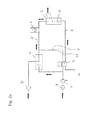
- Fig. 1 schematically shows a preferred embodiment of the device according to the invention for providing an aerosol flow and / or an air flow.
- the device comprises a compressor 1 for providing an air flow and a nebulizing device 2 for generating an aerosol flow.
- the compressor 1 and the nebuliser 2 are connected to each other via a first air channel 4.
- the apparatus further comprises a mixing device 3 for optionally mixing the aerosol flow with the air flow to a total flow.
- the nebulizer 2 and the mixing device 3 are integrated in one component.
- the two devices are present separately and connected to each other by means of an air duct.
- the mixing device is formed with a mouthpiece.
- the mixing device 3 is connected to the compressor 1 via a second air channel 5.
- the air flow provided by the compressor 1 divides into two partial flows, which flow through the two air channels 4 and 5.
- a Venturi nozzle 6 is provided as reinforcing means, which serves to increase the air flow provided by the compressor 1.
- the Venturi nozzle 6 sucks in additional air via the filter 7, which is then forwarded via the second air channel 5 to the mixing device 3.
- the suction port for the compressor 1 has an air filter 8.
- the use of a venturi is advantageous because then a separate pressure relief valve is no longer required.
- the Venturi nozzle replaces the pressure relief valve with a suitable choice of geometry.
- the inhalation flow is independent of the nebulizer geometry.
- nebulizer nozzle is too small (for example, replacing the nebulizers)
- flow through the nebulizer will be reduced, but this will be automatically compensated for by the flow from the compressor flowing more through the venturi, with the compressor designed to do so in that, together with the venturi nozzle and the nebulizer nozzle, an ideal operating point is achieved and no regulation is necessary
- the corresponding pressure conditions are dictated by the geometrical conditions of the nozzles.
- the design shown enables the generation of a sufficiently high pressure to atomize a corresponding agent in the nebuliser 2 by means of a nebulizing nozzle, and the maintenance of a sufficiently large air flow adapted to the patient's respiratory minute volume.
- the compressor 1 provides the necessary pressure and the Venturi nozzle 6 for the sufficient Flow volume.
- This embodiment of the inhalation device has the great advantage that a compressor can be used which can be made smaller in terms of its performance than would actually be necessary to produce the desired pressures and flows.
- the invention enables a deliberate undersizing of the compressor, which saves costs and space in the inhaler housing.
- the in Fig. 1 illustrated preferred device further comprises a bypass channel 9, which can be switched on or off by means of a bypass valve 10.
- the bypass channel is used to bypass the Verneblungscinraum 2.
- the bypass channel 9 is based on the idea; provide a constant total flow, whereby the nebulization can be turned on and off.
- the nebulization is interrupted during the inhalation process, then no air flows through the first air channel 4, so the patient should not be confronted with a reduced flow of air.
- bypass valve 10 being switched so that the air flowing through the first air channel 4 is diverted into the bypass channel 9 and the second air channel 5 when the atomizing device 2 is deactivated.
- the entire air flow provided by the compressor 1 continues to be supplied to the mixing device and thus to the patient.
- excess air may be released through the valve 11.
- the compressor 1 can be switched on and off simply to regulate the air flow.
- the control or regulation of the valves 10 and 11 and the nebulizer 2 via a control device or CPU, which detects by means of a pressure sensor 12, the respective phase of the breathing cycle and the valves or nebulizer corresponding switches.
- the controller preferably further comprises a display as well as buttons for inputting information by the user.
- venturi nozzle 6 and the bypass channel 9 are shown in the illustrated embodiment of the inhalation device, embodiments in which only the venturi nozzle 6 or only the bypass channel 9 are present are also conceivable. Both features each lead to the fact that you can work with a less powerful compressor 1. In combination, a correspondingly stronger effect can be achieved.
- Fig. 2a shows a circuit diagram of the device according to Fig. 1 and the switching state of the valves 10 and 11 and the air flows occurring during inhalation with activated nebulizer.
- the valve 10 is switched so that the compressor 1 is in communication with the nebuliser 2 and the bypass channel 9 blocks.
- Valve 11 is simultaneously switched so that the compressor is connected to the mixing device 3. This results in the airways represented by the arrows. Accordingly, air flows through the filters 7 and 8 into the venturi and the compressor and is provided to the patient via the nebulizer 2 and the mixer 3.
- the bypass channel 9 is not used.
- a flow of 6 1 / min and the Venturi nozzle flows through the first air channel, a flow of 6 1 / min and the Venturi nozzle, a flow of 2.8 1 / min at, for example, 1.6 bar.
- the flow is increased to 9 1 / min, that is spent in the sum of 15 1 / min from the nebulizer to the patient.
- the Venturi nozzle geometry sets the maximum operating pressure.
- the bypass channel would be switched on, so that the flow would be diverted from 6 1 / min via the bypass channel to the second air channel 5 and still flow in total 15 1 / min to the patient.
- Fig. 2b shows a corresponding circuit diagram for inhalation with shut off Vernebelungscinraum. While the valve 11 as in circuit of Fig. 2a remains switched, the valve 10 is now switched to passage for the bypass channel 9. According to the arrows, the air provided by the compressor is now conducted via the bypass channel 9 and the air channel 5 into the mixing device 3 and provided exclusively by the latter to the patient. The nebuliser is inactive. In order to maintain a constant total flow, the air flow passed through the bypass duct 9 is passed through a replacement nozzle 13, which has the same properties as the nebulizer in the nebulizer 2. At the same time, the illustrated circuit of the valve 10 allows immediate venting of the nebulizer 2 via one Venting channel 14. This prevents that remaining in the air duct 4 residual pressure can cause further misting of the active ingredient.
- Fig. 2c shows a corresponding circuit diagram for the exhalation. Again, the arrows represent the corresponding air flows.
- the circuit of the valve 10 corresponds to that of the Fig. 2b .
- valve 11 is now switched so that the air provided by the compressor can escape completely through a vent.
- the connection between the Venturi nozzle or the compressor and the mixing device 3 is prevented, so that an exhalation is prevented in the device.
- Fig. 3 shows an alternative embodiment of the device according to the invention, in which the 3/2 valve, as in Fig. 2 shown replaced by a 4/2 valve.
- the nebulizer can be switched immediately depressurized when switching to the bypass.
- the valve 11 has been replaced by a check valve 17 and provided an additional valve 15 with a venting channel 16 directly behind the compressor 1.
- the check valve 17 that is exhaled into the device. This can be done for example by a silicone membrane.
- the compressor 1 is vented via the vent passage 16, in which a nozzle is installed to hold the operating pressure of the compressor.
- Fig. 4 shows a further embodiment of the invention, in which no venting of the nebulizer nozzle is provided. As previously mentioned, this results in a delayed shutdown of aerosol production, which makes the administration of the drug less precise to control. However, such an embodiment may still be considered for cost reasons.
- FIG. 5 A particularly elegant embodiment using only a single valve 15 5 is in Fig. 5 shown.
- the venting of both the nebulizer and the entire system during exhalation can be done here via a single vent line 16.
- a three-stage switchable 5/3 valve 15 is necessary.
- an additional air duct 18 and two check valves 19 and 20 are to be introduced.
Abstract
Description
Die Erfindung betrifft eine Vorrichtung zum Bereitstellen eines Aersosolflusses und/oder eines Luftflusses und insbesondere ein Inhalationsgerät.The invention relates to a device for providing an aerosol flow and / or an air flow and in particular to an inhalation device.
Inhalation, das heißt das therapeutische Einatmen von Nebel, hat sich als eine wirkungsvolle und schonende Methode bei der Behandlung verschiedener Atemwegserkrankungen wie beispielsweise des akuten Atemweginfektes, der chronischen Bronchitis und insbesondere des Asthma bronchiale erwiesen. Dabei bewirkt die Befeuchtung der Schleimhaut mit einem Nebel von feinsten Tröpfchen eine Schleimlösung in den Atemwegen und fördert dadurch das Abhusten von Sekret. Zusätzlich inhalierte Medikamente können gezielt in den Bronchien oder der Lunge appliziert werden, wo sie zur Behandlung einer topischen sowie auch systemischen Erkrankung wirksam sind. Zur Bereitstellung des Inhalationsnebels oder Aerosols wird üblicherweise ein Düsenvernebler eingesetzt, der unter Einsatz eines Kompressors und einer Vernebelungsdüse den Wirkstoff zerstäubt. Die Eindringtiefe der vernebelten Tröpfchen in die Lunge hängt dabei unter anderem von der Tröpfchengröße ab. Ferner lässt sich die gezielte Wirkung der Tröpfchen dadurch steuern, dass nur während einer bestimmten Zeitspanne innerhalb des Einatemvorganges vernebelt wird.Inhalation, that is, the therapeutic inhalation of fog, has proven to be an effective and gentle method in the treatment of various respiratory diseases such as acute respiratory tract infection, chronic bronchitis, and especially bronchial asthma. Moisturizing the mucous membrane with a mist of fine droplets causes a mucus solution in the respiratory tract and thereby promotes the exhalation of secretions. In addition, inhaled drugs can be targeted to the bronchi or lungs, where they are effective in the treatment of both topical and systemic disease. To provide the inhalation mist or aerosol, a nozzle nebuliser is usually used, which atomizes the active ingredient using a compressor and a nebulizing nozzle. The penetration depth of the nebulized droplets into the lungs depends, among other things, on the droplet size. Furthermore, the targeted effect of the droplets can be controlled by nebulizing only during a certain period of time within the inhalation process.
Daher haben sich Inhalationsgeräte durchgesetzt, bei denen sich der Vernebelungsprozess in Abhängigkeit von der Inhalations- bzw. Exhalationsphase regeln lässt. So beschreibt beispielsweise die
Generell ist es wünschenswert, dass derartige Inhalationsgeräte möglichst klein ausgebildet sind, da insbesondere chronisch kranke Patienten diese Geräte häufig mit sich führen. Die Größe und das Gewicht derartiger Geräte sind dabei häufig durch den Kompressor vorgegeben. Der Kompressor hat dabei die Aufgabe, einerseits einen hinreichend großen Druck zu erzeugen, um die Vernebelungsdüse zu betreiben, und andererseits einen hinreichend großen Luftfluss bereitzustellen, um dem Atemminutenvolumen des Patienten gerecht zu werden. Hoher Druck und gleichzeitig hohe Flüsse verlangen aber nach einem leistungsstarken Kompressor, der entsprechend voluminös bzw. schwer sein kann.In general, it is desirable that such inhalation devices are made as small as possible, especially since chronically ill patients often carry these devices with them. The size and weight of such devices are often specified by the compressor. The compressor has the task on the one hand to generate a sufficiently large pressure to operate the nebulizer, and on the other hand to provide a sufficiently large air flow to meet the respiratory minute volume of the patient. But high pressure and high flows demand a powerful compressor that can be bulky or heavy.
Es ist demnach eine Aufgabe der vorliegenden Erfindung, eine verbesserte Vorrichtung zum Bereitstellen eines Aerosolflusses und/oder eines Luftflusses bereitzustellen. Diese Aufgabe wird mit den Merkmalen der Ansprüche gelöst.It is therefore an object of the present invention to provide an improved apparatus for providing aerosol flow and / or air flow. This object is achieved with the features of the claims.
Der vorliegenden Erfindung liegt die Idee zugrunde, mit einem möglichst kleinen Kompressor einen maximalen Luftfluss bereitzustellen. Dementsprechend betrifft die vorliegende Erfindung eine Vorrichtung zum Bereitstellen eines Aerosolflusses und/oder eines Luftflusses mit mindestens einem Kompressor zum Bereitstellen eines Luftflusses, einer Vernebelungseinrichtung zum Erzeugen eines Aerosolflusses und einer Mischeinrichtung zum optionalen Vermischen des Aerosolflusses mit dem Luftfluss zu einem Gesamtfluss, wobei sich der Gesamtfluss aus dem Aerosolfluss und/oder dem Luftfluss zusammensetzt. Ferner weist die Vorrichtung mindestens einen ersten Luftkanal zwischen dem Kompressor und der Vernebelungsrichtung, mindestens einen zweiten Luftkanal zwischen dem Kompressor und der Mischeinrichtung und mindestens eine Verstärkungseinrichtung zum Erhöhen des von dem Kompressor bereitgestellten Luftflusses auf.The present invention is based on the idea to provide a maximum air flow with the smallest possible compressor. Accordingly, the present invention relates to a device for providing an aerosol flow and / or an air flow with at least one compressor for providing an air flow, a misting device for generating an aerosol flow and a mixing device for optionally mixing the aerosol flow with the air flow to a total flow, wherein the total flow composed of the aerosol flow and / or the air flow. Furthermore, the device has at least one first air channel between the compressor and the atomization direction, at least one second air channel between the compressor and the mixing device and at least one amplifying device for increasing the air flow provided by the compressor.
Entsprechend einem weiteren Aspekt der Erfindung weist die Vorrichtung ferner oder anstelle der Verstärkungseinrichtung einen Bypasskanal auf, der den ersten mit dem zweiten Luftkanal verbindet und der dazu geeignet ist, den Luftfluss in den ersten Luftkanal unter Umgehung der Vernebelungseinrichtung in die Mischeinrichtung umzuleiten. Dieser Bypasskanal kann dabei vorzugsweise mit einem Ventil phasenweise zu- und weggeschaltet werden, wobei ein konstanter Gesamtfluss aufrechterhalten wird.According to a further aspect of the invention, the device further or in place of the amplifying means on a bypass passage which connects the first with the second air duct and which is adapted to redirect the air flow in the first air duct, bypassing the nebuliser in the mixing device. This bypass channel can preferably be switched on and off in phases with a valve, with a constant total flow being maintained.
In einer bevorzugten Ausführungsform der Erfindung weist die Verstärkungseinrichtung mindestens eine Venturidüse auf. Diese ist vorzugsweise entlang des zweiten Luftkanals angeordnet und dazu geeignet, Umgebungsluft in den zweiten Luftkanal hinein anzusaugen, vorzugsweise über einen Filter. Die Venturidüse kann dabei bei einem Arbeitsdruck zwischen 0,5 und 5 bar, vorzugsweise zwischen 0,8 und 3 bar und besonders bevorzugt bei 1,2 bis 2 bar betrieben werden. Der dadurch bereitgestellte Luftfluss liegt in einem Bereich von 1 bis 60 Liter pro Minute. Der Kompressor und die Venturidüse sind dabei vorzugsweise so ausgelegt, dass keine Druck- und/oder Flussregelung notwendig ist.In a preferred embodiment of the invention, the amplification device has at least one Venturi nozzle. This is preferably arranged along the second air channel and suitable for sucking ambient air into the second air channel, preferably via a filter. The Venturi nozzle can be operated at a working pressure of between 0.5 and 5 bar, preferably between 0.8 and 3 bar and more preferably at 1.2 to 2 bar. The air flow provided thereby is in a range of 1 to 60 liters per minute. The compressor and the venturi are preferably designed so that no pressure and / or flow control is necessary.
In einer weiteren bevorzugten Ausführungsform sind zwei oder mehr Verstärkungseinrichtungen vorgesehen. Alternativ kann die Verstärkungsvorrichtung zwei oder mehr vorzugsweise in Reihe geschaltete Venturidüsen aufweisen. Dadurch soll insbesondere sichergestellt werden, dass auch dann ein hinreichender Fluss erreicht wird, wenn die Vernebelungseinrichtung nicht aktiv ist. Der Vorteil der in Reihe geschalteten Venturidüsen zeigt sich besonders bei kleinen Schlauchinnendurchmessern und Schläuchen mit einer Länge von mehr als 1 m. Schläuche mit kleinem Durchmesser und einer Länge von mehr als 1 m erleichtern die Handhabung des Verneblerhandgeräts. Schläuche, wie sie bei Beatmungsgeräten verwendet werden, werden von Patienten nicht akzeptiert und erhöhen das Kontaminationsrisiko, da aufgrund der großen Durchmesser Aerosoltröpfchen leichter in die Luftzuführung gelangen können. Bei der vorliegenden Erfindung kann ein Schlauch mit einer Länge von 0,2 m bis 2 m Durchmesser mit einem Innendurchmesser von 1 bis 20 mm verwendet werden, vorzugsweise wird ein Schlauchdurchmesser mit einem Innendurchmesser von 2 bis 5 mm verwendet mit einer Länge von 0,5 bis 1,5 m. Die Venturidüsen werden so dimensioniert, dass für ein exakt spezifiziertes Schlauchsystem mit bekanntem Durchflusswiderstand bei eingeschalteten und ausgeschalteten Vernebler exakt der gleiche Inspirationsfluss am Mundstück anliegt, ohne dass das Gerät ihn nachregeln muss.In a further preferred embodiment, two or more reinforcing means are provided. Alternatively, the reinforcement device may comprise two or more preferably Venturi nozzles connected in series. This is to ensure in particular that even then a sufficient flow is achieved when the nebulizer is not active. The advantage of the Venturi nozzles connected in series is particularly evident with small hose inner diameters and hoses longer than 1 m. Hoses with a small diameter and a length of more than 1 m facilitate the handling of the nebulizer handset. Hoses, such as those used in ventilators, are not accepted by patients and increase the risk of contamination because aerosol droplets are easier to get into the air supply due to their large diameter. In the present invention, a hose having a length of 0.2 m to 2 m in diameter with an inner diameter of 1 to 20 mm may be used, preferably a hose diameter having an inner diameter of 2 to 5 mm is used with a length of 0.5 up to 1.5 m. The venturi nozzles are dimensioned so that exactly the same inspiratory flow is applied to the mouthpiece for a precisely specified tube system with known flow resistance when the nebuliser is switched on and off, without the instrument having to readjust it.
Die Vorrichtung umfasst ferner bevorzugt eine Steuerungseinrichtung, die den Aerosolfluss und/oder den Luftfluss variieren bzw. vorgeben kann. Dabei soll erfindungsgemäß der Gesamtfluss aus Aerosol und/oder Luftfluss im Wesentlichen zeitlich konstant bleiben. Dieser liegt in einem Bereich zwischen 1 und 60 Liter pro Minute, vorzugsweise zwischen 3 und 50 Liter pro Minute. Die Vernebelungseinrichtung ist dazu geeignet, einen Aerosolfluss von 1 bis 20 Liter pro Minute, vorzugsweise von 3 bis 7 Liter pro Minute und besonders bevorzugt von etwa 6 Liter pro Minute zu erzeugen.The device further preferably comprises a control device that can vary or specify the aerosol flow and / or the air flow. In this case, according to the invention, the total flow of aerosol and / or air flow should remain essentially constant over time. This is in a range between 1 and 60 liters per minute, preferably between 3 and 50 liters per minute. The nebulizer is adapted to produce an aerosol flow of from 1 to 20 liters per minute, preferably from 3 to 7 liters per minute, and more preferably from about 6 liters per minute.
Ferner kann die Vorrichtung optional zumindest ein Rückschlagventil im zweiten Luftkanal aufweisen. Es ist außerdem daran gedacht, ein Entlüftungsventil zwischen Kompressor und Vernebelungseinrichtung einzubringen. Anstelle der Regelung mittels eines Entlüftungsventils ist es auch möglich, den Kompressor ein- bzw. auszuschalten.Furthermore, the device can optionally have at least one check valve in the second air duct. It is also thought to introduce a vent valve between the compressor and nebulizer. Instead of the control by means of a vent valve, it is also possible to turn the compressor on or off.
Um eine Verwendung der Vorrichtung als Inhalationsgerät zu ermöglichen, ist es ferner vorgesehen, die Mischeinrichtung als Mundstück auszulegen.In order to enable use of the device as an inhalation device, it is further provided to design the mixing device as a mouthpiece.
Nachfolgend werden bevorzugte Ausführungsformen der erfindungsgemäßen Vorrichtung unter Bezugnahme auf die Figuren beispielhaft beschrieben. Es zeigen:
- Fig. 1
- eine Prinzipskizze einer bevorzugten Ausführungsform des erfindungsgemäßen Inhalationsgerätes;
- Fig. 2a
- eine Schaltskizze der Vorrichtung gemäß
Fig. 1 mit den auftretenden Luftflüssen während der Inhalation mit eingeschaltetem Vernebler; - Fig. 2b
- eine Schaltskizze der Vorrichtung gemäß
Fig. 1 mit den auftretenden Luftflüssen während der Inhalation bei abgeschaltetem Vernebler; - Fig. 2c
- eine Schaltskizze der Vorrichtung gemäß
Fig. 1 mit den auftretenden Luftflüssen während der Exhalation; - Fig.3 3
- eine Prinzipskizze einer weiteren Ausführungsform des erfindungsgemäßen Inhalationsgerätes;
- Fig. 4
- eine Prinzipskizze einer weiteren Ausführungsform des erfindungsgemäßen Inhalationsgerätes; und
- Fig. 5
- eine Prinzipskizze einer weiteren Ausführungsform des erfindungsgemäßen Inhalationsgerätes.
- Fig. 1
- a schematic diagram of a preferred embodiment of the inhalation device according to the invention;
- Fig. 2a
- a circuit diagram of the device according to
Fig. 1 with the occurring airflows during the inhalation with activated nebuliser; - Fig. 2b
- a circuit diagram of the device according to
Fig. 1 with the occurring air flows during the inhalation with the nebulizer switched off; - Fig. 2c
- a circuit diagram of the device according to
Fig. 1 with the occurring airflows during the exhalation; - 3
- a schematic diagram of another embodiment of the inhalation device according to the invention;
- Fig. 4
- a schematic diagram of another embodiment of the inhalation device according to the invention; and
- Fig. 5
- a schematic diagram of another embodiment of the inhalation device according to the invention.
Die Mischeinrichtung 3 ist über einen zweiten Luftkanal 5 mit dem Kompressor 1 verbunden. Dadurch teilt sich der von dem Kompressor 1 bereitgestellte Luftfluss in zwei Teilflüsse auf, die durch die beiden Luftkanäle 4 und 5 strömen. Im zweiten Luftkanal 5 ist als Verstärkungseinrichtung eine Venturidüse 6 vorgesehen, die der Erhöhung des von dem Kompressor 1 bereitgestellten Luftflusses dient. Die Venturidüse 6 saugt zusätzliche Luft über den Filter 7 an, die dann über den zweiten Luftkanal 5 an die Mischeinrichtung 3 weitergeleitet wird. Alternativ zu der in
Auch die Ansaugöffnung für den Kompressor 1 weist einen Luftfilter 8 auf. Die Verwendung einer Venturidüse ist vorteilhaft, da dann ein separates Überdruckventil nicht mehr erforderlich ist. Die Venturidüse ersetzt durch geeignete Geometriewahl das Überdruckventil. Ferner ist der Inhalationsfluss unabhängig von der Verneblergeometrie. Ist beispielsweise die Verneblerdüse zu klein (beispielsweise bei einem Austausch der Vernebler, wird dadurch der Fluß über den Vernebler geringer. Dies wird jedoch automatisch dadurch ausgeglichen, dass dann von dem vom Kompressor bereitgestellten Fluss mehr über die Venturidüse fließt. Der Kompressor ist dabei so ausgelegt, dass zusammen mit der Venturidüse und der Verneblerdüse ein idealer Arbeitspunkt erreicht wird und keine Regelung mehr erforderlich ist. Die entsprechenden Druckverhältnisse werden durch die geometrischen Verhältnisse der Düsen vorgegeben. Erfindungsgemäß bleibt der Inhalationsfluss immer gleich, lediglich das Inhalationsvolumen wird patientenabhängig eingestellt.Also, the suction port for the compressor 1 has an air filter 8. The use of a venturi is advantageous because then a separate pressure relief valve is no longer required. The Venturi nozzle replaces the pressure relief valve with a suitable choice of geometry. Furthermore, the inhalation flow is independent of the nebulizer geometry. For example, if the nebulizer nozzle is too small (for example, replacing the nebulizers), flow through the nebulizer will be reduced, but this will be automatically compensated for by the flow from the compressor flowing more through the venturi, with the compressor designed to do so in that, together with the venturi nozzle and the nebulizer nozzle, an ideal operating point is achieved and no regulation is necessary The corresponding pressure conditions are dictated by the geometrical conditions of the nozzles.
Das in
Erfindungsgemäß weist die in
Die Steuerung bzw. Regelung der Ventile 10 und 11 sowie der Vernebelungseinrichtung 2 geschieht über eine Steuerungseinrichtung bzw. CPU, die mittels eines Drucksensors 12 die jeweilige Phase des Atemzyklus erfasst und die Ventile bzw. die Vernebelungseinrichtung entsprechend schaltet. Die Steuerungseinrichtung weist vorzugsweise ferner ein Display sowie Tasten zur Eingabe von Informationen durch den Benutzer auf.The control or regulation of the
Obwohl in der dargestellten Ausführungsform des Inhalatiansgerätes sowohl die Venturidüse 6 als auch der Bypasskanal 9 dargestellt sind, sind auch Ausführungsformen vorstellbar, in denen nur die Venturidüse 6 oder nur der Bypasskanal 9 vorhanden sind. Beide Merkmale führen jeweils für sich genommen dazu, dass mit einem leistungsschwächeren Kompressor 1 gearbeitet werden kann. In Kombination kann ein entsprechend stärkerer Effekt erzielt werden.Although both the
Eine besonders elegante Ausführungsform unter Verwendung nur eines einzigen Ventils 15 5 ist in
Claims (17)
Priority Applications (2)
| Application Number | Priority Date | Filing Date | Title |
|---|---|---|---|
| PL08163652T PL2033675T3 (en) | 2007-09-06 | 2008-09-04 | Inhalation device |
| EP08163652.4A EP2033675B1 (en) | 2007-09-06 | 2008-09-04 | Inhalation device |
Applications Claiming Priority (2)
| Application Number | Priority Date | Filing Date | Title |
|---|---|---|---|
| EP07115812A EP2033674A1 (en) | 2007-09-06 | 2007-09-06 | Inhalation device |
| EP08163652.4A EP2033675B1 (en) | 2007-09-06 | 2008-09-04 | Inhalation device |
Publications (3)
| Publication Number | Publication Date |
|---|---|
| EP2033675A2 true EP2033675A2 (en) | 2009-03-11 |
| EP2033675A3 EP2033675A3 (en) | 2010-11-10 |
| EP2033675B1 EP2033675B1 (en) | 2014-07-09 |
Family
ID=38984289
Family Applications (2)
| Application Number | Title | Priority Date | Filing Date |
|---|---|---|---|
| EP07115812A Ceased EP2033674A1 (en) | 2007-09-06 | 2007-09-06 | Inhalation device |
| EP08163652.4A Active EP2033675B1 (en) | 2007-09-06 | 2008-09-04 | Inhalation device |
Family Applications Before (1)
| Application Number | Title | Priority Date | Filing Date |
|---|---|---|---|
| EP07115812A Ceased EP2033674A1 (en) | 2007-09-06 | 2007-09-06 | Inhalation device |
Country Status (7)
| Country | Link |
|---|---|
| US (1) | US8181644B2 (en) |
| EP (2) | EP2033674A1 (en) |
| CA (1) | CA2639321C (en) |
| DK (1) | DK2033675T3 (en) |
| ES (1) | ES2498818T3 (en) |
| PL (1) | PL2033675T3 (en) |
| PT (1) | PT2033675E (en) |
Families Citing this family (10)
| Publication number | Priority date | Publication date | Assignee | Title |
|---|---|---|---|---|
| KR101237131B1 (en) * | 2010-09-24 | 2013-02-25 | 서울대학교산학협력단 | An Improved Apparatus for Treating or Testing Toxic Properties by Inhaling a Liquid-Phase Material |
| EP2724741B1 (en) * | 2012-10-26 | 2017-06-14 | Vectura GmbH | Inhalation device for use in aerosol therapy |
| US10220109B2 (en) | 2014-04-18 | 2019-03-05 | Todd H. Becker | Pest control system and method |
| CA2950592C (en) | 2014-04-18 | 2020-08-25 | Thomas A. CONROY | Method and system of a network of diffusers including a liquid level sensor |
| AU2017306411B2 (en) | 2016-08-03 | 2022-03-31 | Scentbridge Holdings, Llc | Method and system of a networked scent diffusion device |
| CN107050593A (en) * | 2017-05-27 | 2017-08-18 | 重庆智阖康医疗器械有限公司 | A kind of portable multiple terminals air supply system |
| KR101964731B1 (en) * | 2017-08-28 | 2019-04-02 | 한국화학연구원 | Primary Particulate Matter Generating System |
| KR101946301B1 (en) | 2017-08-28 | 2019-02-11 | 한국화학연구원 | Multi Particulate Matter Generating System |
| WO2020232236A1 (en) | 2019-05-16 | 2020-11-19 | Aerovate Therapeutics, Inc. | Imatinib formulations, manufacture, and uses thereof |
| US20230364355A1 (en) | 2020-09-28 | 2023-11-16 | Vectura Delivery Devices Limited | Inhalation device |
Citations (2)
| Publication number | Priority date | Publication date | Assignee | Title |
|---|---|---|---|---|
| DE19939417A1 (en) | 1999-08-20 | 2001-03-01 | Mpv Truma Ges Fuer Medizintech | Apparatus for administering medicaments through inhalation comprises pressure sensor forming part of control system which governs atomization process via valve in compressed air line to atomizing unit |
| EP1700614A1 (en) | 2005-03-08 | 2006-09-13 | Activaero GmbH | Inhalation device |
Family Cites Families (15)
| Publication number | Priority date | Publication date | Assignee | Title |
|---|---|---|---|---|
| US3842828A (en) * | 1972-09-08 | 1974-10-22 | Bird F M | Pediatric ventilator |
| US3817246A (en) * | 1972-12-11 | 1974-06-18 | Puritan Bennett Corp | Flow responsive respiration apparatus |
| US3916888A (en) * | 1973-10-04 | 1975-11-04 | Tecna Corp | Respirator |
| US5007420A (en) * | 1981-08-10 | 1991-04-16 | Bird F M | Ventilator having an oscillatory inspiratory phase and method |
| US5237987A (en) * | 1990-06-07 | 1993-08-24 | Infrasonics, Inc. | Human lung ventilator system |
| US5666946A (en) * | 1994-07-13 | 1997-09-16 | Respirogenics Corporation | Apparatus for delivering drugs to the lungs |
| US5823179A (en) * | 1996-02-13 | 1998-10-20 | 1263152 Ontario Inc. | Nebulizer apparatus and method |
| FR2767492B1 (en) * | 1997-08-25 | 1999-10-29 | Prolitec | HEAD AND NEBULIZATION DEVICE AND DEVICE FOR HOMOGENOUS MIXING OF NATURALLY NON-MISCIBLE LIQUIDS |
| US8820316B2 (en) * | 2000-02-11 | 2014-09-02 | Respironics Respiratory Drug Delivery (Uk) Ltd | Drug delivery apparatus |
| DE10322964B4 (en) * | 2003-05-21 | 2006-03-23 | Seleon Gmbh | Control unit for anti-snoring device and anti-snoring device |
| US7191780B2 (en) * | 2003-09-22 | 2007-03-20 | Comedica Incorporated | Continuous high-frequency oscillation breathing treatment apparatus |
| GB0500677D0 (en) * | 2005-01-14 | 2005-02-23 | Britannia Pharmaceuticals Ltd | Dry powder inhaler |
| US7870857B2 (en) * | 2005-05-23 | 2011-01-18 | Aeon Research And Technology, Inc. | Patient interface assemblies for use in ventilator systems to deliver medication to a patient |
| GB0617417D0 (en) * | 2006-09-05 | 2006-10-18 | Concept 2 Manufacture Design L | A nebuliser valve |
| US8051854B2 (en) * | 2006-09-15 | 2011-11-08 | Comedica Incorporated | Continuous high-frequency oscillation breathing treatment apparatus |
-
2007
- 2007-09-06 EP EP07115812A patent/EP2033674A1/en not_active Ceased
-
2008
- 2008-09-04 DK DK08163652.4T patent/DK2033675T3/en active
- 2008-09-04 ES ES08163652.4T patent/ES2498818T3/en active Active
- 2008-09-04 PT PT81636524T patent/PT2033675E/en unknown
- 2008-09-04 US US12/204,037 patent/US8181644B2/en active Active
- 2008-09-04 EP EP08163652.4A patent/EP2033675B1/en active Active
- 2008-09-04 PL PL08163652T patent/PL2033675T3/en unknown
- 2008-09-04 CA CA2639321A patent/CA2639321C/en active Active
Patent Citations (2)
| Publication number | Priority date | Publication date | Assignee | Title |
|---|---|---|---|---|
| DE19939417A1 (en) | 1999-08-20 | 2001-03-01 | Mpv Truma Ges Fuer Medizintech | Apparatus for administering medicaments through inhalation comprises pressure sensor forming part of control system which governs atomization process via valve in compressed air line to atomizing unit |
| EP1700614A1 (en) | 2005-03-08 | 2006-09-13 | Activaero GmbH | Inhalation device |
Also Published As
| Publication number | Publication date |
|---|---|
| US8181644B2 (en) | 2012-05-22 |
| CA2639321A1 (en) | 2009-03-06 |
| PT2033675E (en) | 2014-09-23 |
| US20090064995A1 (en) | 2009-03-12 |
| PL2033675T3 (en) | 2014-11-28 |
| EP2033674A1 (en) | 2009-03-11 |
| EP2033675B1 (en) | 2014-07-09 |
| DK2033675T3 (en) | 2014-09-08 |
| ES2498818T3 (en) | 2014-09-25 |
| EP2033675A3 (en) | 2010-11-10 |
| CA2639321C (en) | 2016-02-16 |
Similar Documents
| Publication | Publication Date | Title |
|---|---|---|
| EP2033675B1 (en) | Inhalation device | |
| DE69633306T2 (en) | VENTILATION FOR A SPRAYER | |
| EP2298399B1 (en) | Anaesthetic device and method for operating same | |
| DE69729071T2 (en) | NEBULIZER | |
| EP3164183B1 (en) | Respiratory device | |
| EP1736193B1 (en) | Inhaler | |
| EP1695730B1 (en) | Component for an inhalation device and an inhalation device with this component | |
| EP0281650A1 (en) | Aerosol sprayer | |
| EP3479860B1 (en) | Device for respiration therapy | |
| DE102008050218A1 (en) | Inhalable material e.g. liquid aerosol, applying system for e.g. isolated lung of ex-vivo rabbit, has controller for operating nebulizer at beginning or during inspiration phase and stopping nebulizer during termination of inspiration phase | |
| EP3694592B1 (en) | Device for ventilating a patient | |
| WO2017148639A1 (en) | Method and device for ventilating a patient | |
| EP3484561A1 (en) | Inhalation method with controlled cyclic activation | |
| DE60003217T2 (en) | INHALATOR FOR TREATING THE BRONCHIA OF HORSES | |
| EP1107809A1 (en) | Inhalator for atomizing liquids | |
| EP1772165A1 (en) | Inhalation apparatus | |
| WO2018033224A1 (en) | Device for administering artificial respiration to a patient and method for operating the device | |
| DE60309241T2 (en) | Respiratory device with a nebulizer | |
| DE102005039502A1 (en) | Mouthpiece for medicament inhaler, comprises peripheral double wall structure, forming inner nozzle for medicament-containing core jet and outer nozzle for sheath jet of air to improve drug delivery to lungs | |
| DE102017101645A1 (en) | Apparatus and methods for ventilating a patient | |
| DE202004004809U1 (en) | Breathing therapy device for cystic fibrosis and bronchitis has an oxygen supply unit for feeding concentrated oxygen to a releasing unit connected to the outlet side of the compressor for supplying air impulses to the user | |
| DE3908909C2 (en) | ||
| EP3936177B1 (en) | Breathing apparatus | |
| DE2735028A1 (en) | Medical respiratory appts. with medicament spray - has logic controlled double membrane valve synchronising breathing and spray supplies | |
| DE2062632A1 (en) | Inhalation device |
Legal Events
| Date | Code | Title | Description |
|---|---|---|---|
| PUAI | Public reference made under article 153(3) epc to a published international application that has entered the european phase |
Free format text: ORIGINAL CODE: 0009012 |
|
| AK | Designated contracting states |
Kind code of ref document: A2 Designated state(s): AT BE BG CH CY CZ DE DK EE ES FI FR GB GR HR HU IE IS IT LI LT LU LV MC MT NL NO PL PT RO SE SI SK TR |
|
| AX | Request for extension of the european patent |
Extension state: AL BA MK RS |
|
| PUAL | Search report despatched |
Free format text: ORIGINAL CODE: 0009013 |
|
| AK | Designated contracting states |
Kind code of ref document: A3 Designated state(s): AT BE BG CH CY CZ DE DK EE ES FI FR GB GR HR HU IE IS IT LI LT LU LV MC MT NL NO PL PT RO SE SI SK TR |
|
| AX | Request for extension of the european patent |
Extension state: AL BA MK RS |
|
| 17P | Request for examination filed |
Effective date: 20110504 |
|
| RIN1 | Information on inventor provided before grant (corrected) |
Inventor name: KOLB, TOBIAS Inventor name: FREY, MANUEL Inventor name: MUELLINGER, BERNHARD Inventor name: HOFFMANN, TOBIAS |
|
| AKX | Designation fees paid |
Designated state(s): AT BE BG CH CY CZ DE DK EE ES FI FR GB GR HR HU IE IS IT LI LT LU LV MC MT NL NO PL PT RO SE SI SK TR |
|
| 17Q | First examination report despatched |
Effective date: 20130307 |
|
| GRAP | Despatch of communication of intention to grant a patent |
Free format text: ORIGINAL CODE: EPIDOSNIGR1 |
|
| RIC1 | Information provided on ipc code assigned before grant |
Ipc: A61M 11/02 20060101AFI20140103BHEP Ipc: A61M 16/10 20060101ALI20140103BHEP Ipc: A61M 16/00 20060101ALI20140103BHEP |
|
| INTG | Intention to grant announced |
Effective date: 20140127 |
|
| GRAS | Grant fee paid |
Free format text: ORIGINAL CODE: EPIDOSNIGR3 |
|
| GRAA | (expected) grant |
Free format text: ORIGINAL CODE: 0009210 |
|
| RAP1 | Party data changed (applicant data changed or rights of an application transferred) |
Owner name: VECTURA GMBH |
|
| AK | Designated contracting states |
Kind code of ref document: B1 Designated state(s): AT BE BG CH CY CZ DE DK EE ES FI FR GB GR HR HU IE IS IT LI LT LU LV MC MT NL NO PL PT RO SE SI SK TR |
|
| REG | Reference to a national code |
Ref country code: GB Ref legal event code: FG4D Free format text: NOT ENGLISH |
|
| REG | Reference to a national code |
Ref country code: AT Ref legal event code: REF Ref document number: 676343 Country of ref document: AT Kind code of ref document: T Effective date: 20140715 Ref country code: CH Ref legal event code: EP |
|
| REG | Reference to a national code |
Ref country code: IE Ref legal event code: FG4D Free format text: LANGUAGE OF EP DOCUMENT: GERMAN |
|
| REG | Reference to a national code |
Ref country code: CH Ref legal event code: NV Representative=s name: VOSSIUS AND PARTNER, CH |
|
| REG | Reference to a national code |
Ref country code: DE Ref legal event code: R096 Ref document number: 502008011991 Country of ref document: DE Effective date: 20140821 |
|
| REG | Reference to a national code |
Ref country code: DK Ref legal event code: T3 Effective date: 20140903 |
|
| REG | Reference to a national code |
Ref country code: PT Ref legal event code: SC4A Free format text: AVAILABILITY OF NATIONAL TRANSLATION Effective date: 20140917 |
|
| REG | Reference to a national code |
Ref country code: ES Ref legal event code: FG2A Ref document number: 2498818 Country of ref document: ES Kind code of ref document: T3 Effective date: 20140925 |
|
| REG | Reference to a national code |
Ref country code: SE Ref legal event code: TRGR |
|
| REG | Reference to a national code |
Ref country code: NL Ref legal event code: T3 |
|
| REG | Reference to a national code |
Ref country code: PL Ref legal event code: T3 |
|
| REG | Reference to a national code |
Ref country code: LT Ref legal event code: MG4D |
|
| PG25 | Lapsed in a contracting state [announced via postgrant information from national office to epo] |
Ref country code: NO Free format text: LAPSE BECAUSE OF FAILURE TO SUBMIT A TRANSLATION OF THE DESCRIPTION OR TO PAY THE FEE WITHIN THE PRESCRIBED TIME-LIMIT Effective date: 20141009 Ref country code: FI Free format text: LAPSE BECAUSE OF FAILURE TO SUBMIT A TRANSLATION OF THE DESCRIPTION OR TO PAY THE FEE WITHIN THE PRESCRIBED TIME-LIMIT Effective date: 20140709 Ref country code: GR Free format text: LAPSE BECAUSE OF FAILURE TO SUBMIT A TRANSLATION OF THE DESCRIPTION OR TO PAY THE FEE WITHIN THE PRESCRIBED TIME-LIMIT Effective date: 20141010 Ref country code: BG Free format text: LAPSE BECAUSE OF FAILURE TO SUBMIT A TRANSLATION OF THE DESCRIPTION OR TO PAY THE FEE WITHIN THE PRESCRIBED TIME-LIMIT Effective date: 20141009 Ref country code: LT Free format text: LAPSE BECAUSE OF FAILURE TO SUBMIT A TRANSLATION OF THE DESCRIPTION OR TO PAY THE FEE WITHIN THE PRESCRIBED TIME-LIMIT Effective date: 20140709 |
|
| PG25 | Lapsed in a contracting state [announced via postgrant information from national office to epo] |
Ref country code: IS Free format text: LAPSE BECAUSE OF FAILURE TO SUBMIT A TRANSLATION OF THE DESCRIPTION OR TO PAY THE FEE WITHIN THE PRESCRIBED TIME-LIMIT Effective date: 20141109 Ref country code: LV Free format text: LAPSE BECAUSE OF FAILURE TO SUBMIT A TRANSLATION OF THE DESCRIPTION OR TO PAY THE FEE WITHIN THE PRESCRIBED TIME-LIMIT Effective date: 20140709 Ref country code: CY Free format text: LAPSE BECAUSE OF FAILURE TO SUBMIT A TRANSLATION OF THE DESCRIPTION OR TO PAY THE FEE WITHIN THE PRESCRIBED TIME-LIMIT Effective date: 20140709 Ref country code: HR Free format text: LAPSE BECAUSE OF FAILURE TO SUBMIT A TRANSLATION OF THE DESCRIPTION OR TO PAY THE FEE WITHIN THE PRESCRIBED TIME-LIMIT Effective date: 20140709 |
|
| REG | Reference to a national code |
Ref country code: DE Ref legal event code: R097 Ref document number: 502008011991 Country of ref document: DE |
|
| PG25 | Lapsed in a contracting state [announced via postgrant information from national office to epo] |
Ref country code: EE Free format text: LAPSE BECAUSE OF FAILURE TO SUBMIT A TRANSLATION OF THE DESCRIPTION OR TO PAY THE FEE WITHIN THE PRESCRIBED TIME-LIMIT Effective date: 20140709 Ref country code: LU Free format text: LAPSE BECAUSE OF FAILURE TO SUBMIT A TRANSLATION OF THE DESCRIPTION OR TO PAY THE FEE WITHIN THE PRESCRIBED TIME-LIMIT Effective date: 20140904 Ref country code: MC Free format text: LAPSE BECAUSE OF FAILURE TO SUBMIT A TRANSLATION OF THE DESCRIPTION OR TO PAY THE FEE WITHIN THE PRESCRIBED TIME-LIMIT Effective date: 20140709 Ref country code: CZ Free format text: LAPSE BECAUSE OF FAILURE TO SUBMIT A TRANSLATION OF THE DESCRIPTION OR TO PAY THE FEE WITHIN THE PRESCRIBED TIME-LIMIT Effective date: 20140709 Ref country code: RO Free format text: LAPSE BECAUSE OF FAILURE TO SUBMIT A TRANSLATION OF THE DESCRIPTION OR TO PAY THE FEE WITHIN THE PRESCRIBED TIME-LIMIT Effective date: 20140709 Ref country code: SK Free format text: LAPSE BECAUSE OF FAILURE TO SUBMIT A TRANSLATION OF THE DESCRIPTION OR TO PAY THE FEE WITHIN THE PRESCRIBED TIME-LIMIT Effective date: 20140709 |
|
| PLBE | No opposition filed within time limit |
Free format text: ORIGINAL CODE: 0009261 |
|
| STAA | Information on the status of an ep patent application or granted ep patent |
Free format text: STATUS: NO OPPOSITION FILED WITHIN TIME LIMIT |
|
| 26N | No opposition filed |
Effective date: 20150410 |
|
| REG | Reference to a national code |
Ref country code: IE Ref legal event code: MM4A |
|
| PG25 | Lapsed in a contracting state [announced via postgrant information from national office to epo] |
Ref country code: IE Free format text: LAPSE BECAUSE OF NON-PAYMENT OF DUE FEES Effective date: 20140904 |
|
| REG | Reference to a national code |
Ref country code: FR Ref legal event code: PLFP Year of fee payment: 8 |
|
| PG25 | Lapsed in a contracting state [announced via postgrant information from national office to epo] |
Ref country code: SI Free format text: LAPSE BECAUSE OF FAILURE TO SUBMIT A TRANSLATION OF THE DESCRIPTION OR TO PAY THE FEE WITHIN THE PRESCRIBED TIME-LIMIT Effective date: 20140709 |
|
| PG25 | Lapsed in a contracting state [announced via postgrant information from national office to epo] |
Ref country code: MT Free format text: LAPSE BECAUSE OF FAILURE TO SUBMIT A TRANSLATION OF THE DESCRIPTION OR TO PAY THE FEE WITHIN THE PRESCRIBED TIME-LIMIT Effective date: 20140709 |
|
| REG | Reference to a national code |
Ref country code: CH Ref legal event code: PFA Owner name: VECTURA GMBH, DE Free format text: FORMER OWNER: VECTURA GMBH, DE |
|
| PG25 | Lapsed in a contracting state [announced via postgrant information from national office to epo] |
Ref country code: TR Free format text: LAPSE BECAUSE OF FAILURE TO SUBMIT A TRANSLATION OF THE DESCRIPTION OR TO PAY THE FEE WITHIN THE PRESCRIBED TIME-LIMIT Effective date: 20140709 Ref country code: HU Free format text: LAPSE BECAUSE OF FAILURE TO SUBMIT A TRANSLATION OF THE DESCRIPTION OR TO PAY THE FEE WITHIN THE PRESCRIBED TIME-LIMIT; INVALID AB INITIO Effective date: 20080904 |
|
| REG | Reference to a national code |
Ref country code: CH Ref legal event code: PCOW Free format text: NEW ADDRESS: ROBERT-KOCH-ALLEE 29, 82131 GAUTING (DE) |
|
| REG | Reference to a national code |
Ref country code: DE Ref legal event code: R082 Ref document number: 502008011991 Country of ref document: DE Ref country code: DE Ref legal event code: R082 Ref document number: 502008011991 Country of ref document: DE Representative=s name: FDST PATENTANWAELTE FREIER DOERR STAMMLER TSCH, DE Ref country code: DE Ref legal event code: R081 Ref document number: 502008011991 Country of ref document: DE Owner name: VECTURA GMBH, DE Free format text: FORMER OWNER: VECTURA GMBH, 35285 GEMUENDEN, DE |
|
| REG | Reference to a national code |
Ref country code: DE Ref legal event code: R082 Ref document number: 502008011991 Country of ref document: DE |
|
| REG | Reference to a national code |
Ref country code: FR Ref legal event code: PLFP Year of fee payment: 9 |
|
| REG | Reference to a national code |
Ref country code: FR Ref legal event code: CA Effective date: 20170316 |
|
| REG | Reference to a national code |
Ref country code: FR Ref legal event code: PLFP Year of fee payment: 10 |
|
| REG | Reference to a national code |
Ref country code: FR Ref legal event code: PLFP Year of fee payment: 11 |
|
| P01 | Opt-out of the competence of the unified patent court (upc) registered |
Effective date: 20230418 |
|
| PGFP | Annual fee paid to national office [announced via postgrant information from national office to epo] |
Ref country code: NL Payment date: 20230926 Year of fee payment: 16 Ref country code: IT Payment date: 20230921 Year of fee payment: 16 Ref country code: GB Payment date: 20230927 Year of fee payment: 16 Ref country code: AT Payment date: 20230821 Year of fee payment: 16 |
|
| PGFP | Annual fee paid to national office [announced via postgrant information from national office to epo] |
Ref country code: SE Payment date: 20230927 Year of fee payment: 16 Ref country code: PT Payment date: 20230831 Year of fee payment: 16 Ref country code: PL Payment date: 20230821 Year of fee payment: 16 Ref country code: FR Payment date: 20230925 Year of fee payment: 16 Ref country code: DK Payment date: 20230927 Year of fee payment: 16 Ref country code: DE Payment date: 20230927 Year of fee payment: 16 Ref country code: BE Payment date: 20230927 Year of fee payment: 16 |
|
| PGFP | Annual fee paid to national office [announced via postgrant information from national office to epo] |
Ref country code: ES Payment date: 20231002 Year of fee payment: 16 |
|
| PGFP | Annual fee paid to national office [announced via postgrant information from national office to epo] |
Ref country code: CH Payment date: 20231004 Year of fee payment: 16 |