EP2034651A2 - Method and apparatus for multi-rate control in a multi-channel communication system - Google Patents
Method and apparatus for multi-rate control in a multi-channel communication system Download PDFInfo
- Publication number
- EP2034651A2 EP2034651A2 EP08163901A EP08163901A EP2034651A2 EP 2034651 A2 EP2034651 A2 EP 2034651A2 EP 08163901 A EP08163901 A EP 08163901A EP 08163901 A EP08163901 A EP 08163901A EP 2034651 A2 EP2034651 A2 EP 2034651A2
- Authority
- EP
- European Patent Office
- Prior art keywords
- bits
- channel
- rate
- group
- ratio
- Prior art date
- Legal status (The legal status is an assumption and is not a legal conclusion. Google has not performed a legal analysis and makes no representation as to the accuracy of the status listed.)
- Withdrawn
Links
Images


Classifications
-
- H—ELECTRICITY
- H04—ELECTRIC COMMUNICATION TECHNIQUE
- H04L—TRANSMISSION OF DIGITAL INFORMATION, e.g. TELEGRAPHIC COMMUNICATION
- H04L1/00—Arrangements for detecting or preventing errors in the information received
- H04L1/0001—Systems modifying transmission characteristics according to link quality, e.g. power backoff
- H04L1/0009—Systems modifying transmission characteristics according to link quality, e.g. power backoff by adapting the channel coding
- H04L1/0013—Rate matching, e.g. puncturing or repetition of code symbols
-
- H—ELECTRICITY
- H04—ELECTRIC COMMUNICATION TECHNIQUE
- H04B—TRANSMISSION
- H04B7/00—Radio transmission systems, i.e. using radiation field
- H04B7/02—Diversity systems; Multi-antenna system, i.e. transmission or reception using multiple antennas
- H04B7/04—Diversity systems; Multi-antenna system, i.e. transmission or reception using multiple antennas using two or more spaced independent antennas
- H04B7/06—Diversity systems; Multi-antenna system, i.e. transmission or reception using multiple antennas using two or more spaced independent antennas at the transmitting station
- H04B7/0613—Diversity systems; Multi-antenna system, i.e. transmission or reception using multiple antennas using two or more spaced independent antennas at the transmitting station using simultaneous transmission
- H04B7/0615—Diversity systems; Multi-antenna system, i.e. transmission or reception using multiple antennas using two or more spaced independent antennas at the transmitting station using simultaneous transmission of weighted versions of same signal
- H04B7/0617—Diversity systems; Multi-antenna system, i.e. transmission or reception using multiple antennas using two or more spaced independent antennas at the transmitting station using simultaneous transmission of weighted versions of same signal for beam forming
-
- H—ELECTRICITY
- H04—ELECTRIC COMMUNICATION TECHNIQUE
- H04L—TRANSMISSION OF DIGITAL INFORMATION, e.g. TELEGRAPHIC COMMUNICATION
- H04L1/00—Arrangements for detecting or preventing errors in the information received
- H04L1/004—Arrangements for detecting or preventing errors in the information received by using forward error control
- H04L1/0056—Systems characterized by the type of code used
- H04L1/0067—Rate matching
-
- H—ELECTRICITY
- H04—ELECTRIC COMMUNICATION TECHNIQUE
- H04L—TRANSMISSION OF DIGITAL INFORMATION, e.g. TELEGRAPHIC COMMUNICATION
- H04L1/00—Arrangements for detecting or preventing errors in the information received
- H04L1/004—Arrangements for detecting or preventing errors in the information received by using forward error control
- H04L1/0056—Systems characterized by the type of code used
- H04L1/0071—Use of interleaving
-
- H—ELECTRICITY
- H04—ELECTRIC COMMUNICATION TECHNIQUE
- H04L—TRANSMISSION OF DIGITAL INFORMATION, e.g. TELEGRAPHIC COMMUNICATION
- H04L1/00—Arrangements for detecting or preventing errors in the information received
- H04L1/02—Arrangements for detecting or preventing errors in the information received by diversity reception
- H04L1/06—Arrangements for detecting or preventing errors in the information received by diversity reception using space diversity
Definitions
- the present invention generally relates to data communications and, more particularly, to data processing for transmission in a multi-channel communication system.
- a multi-channel communication system may refer to a wireless communication system capable of transmitting information such as voice and data between a transmitter and a receiver, which may have more than one transmitter antenna and receiver antenna, respectively.
- a multi-channel system may include, for example, a multiple-input multiple-output (MIMO) communication system, an orthogonal frequency division modulation (OFDM) system and a MIMO system based on OFDM.
- MIMO multiple-input multiple-output
- OFDM orthogonal frequency division modulation
- a MIMO system may employ multiple transmitter antennas and multiple receiver antennas to exploit spatial diversity to support a number of spatial subchannels, each of which may be used to transmit data.
- An OFDM system may partition an operating frequency band into a number of frequency subchannels, each of which is associated with a respective subcarrier on which data may be modulated.
- a multi-channel communication system thus may support a number of "transmission" channels," each of which may correspond to a spatial subchannel in a MIMO system, a frequency subchannel in an OFDM system, or a spatial subchannel of a frequency subchannel in a MIMO system that utilizes OFDM.
- transmission channels may experience different channel conditions due to, for example, different fading and multipath effects, and may therefore result in different signal-to-interference-plus-noise ratios (SNRs). Consequently, the transmission capacities (i.e., the information bit rates) that may be supported by the transmission channels for a particular level of performance may be different from channel to channel. Moreover, the channel conditions may often vary over time. As a result, the bit rates supported by the transmission channels may also vary with time.
- a coding and modulation scheme MCS may be configured to process data prior to transmission via the channels so as to enhance transmission capacities.
- the MCS may be divided into a single codeword (SCW) architecture and a multi codeword (MCW) architecture.
- FIG. 1A is a schematic block diagram of an exemplary transmitter 1 based on an SCW scheme in a MIMO system.
- the transmitter 1 may include an encoder 11, a rate matcher 12, a channel interleaver 13, a modulator 14, a layer mapper 15, a precoder 16, a number of antennas 17-1 to 17-n and a controller 18.
- the encoder 11 receives a code block containing information bits in a bit stream. Encoder 11 then encodes the received information bits with a code scheme, for example, a 1/3-rate Turbo code (TC) with tail bit addition.
- TC 1/3-rate Turbo code
- rate matching is performed under the control of the controller 18, which in turn may receive a feedback signal from a receiver to determine a code rate for the channel.
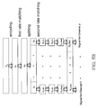
- FIG. 1B is a flow diagram illustrating data processing in terms of bit size in the transmitter 1 illustrated in FIG. 1A .
- a number of "N b " information bits are received by the encoder 11.
- the coded bits have a size of (3 N b +12) bits.
- puncturing or repetition, depending on the channel condition may be performed in the rate matcher 12, resulting in an output of N p bits, where N p is the total amount of bits to be transmitted.
- the number of N p may be determined by the controller 18 according to the channel condition.
- the N p bits are interleaved in the channel interleaver 13.
- the modulator 14 modulates the interleaved N p bits and generates a number of "N p /m" symbols, where the value "m” may also be determined by the controller 18.
- the modulated N p /m symbols are de-multiplexed in the layer mapper 15 before precoded in the precoder 16. For simplicity, it may be assumed that two antennas 17-1 and 17-2 are utilized to transmit N p /2m symbols each.
- the SCW scheme described and illustrated with reference to FIG. 1A may have a relatively simple structure and a relatively low feedback overhead, the performance such as error probability and data rate may not be desirable.
- the channel 17-1 may have a better link condition than the channel 17-2 during a certain period of transmission and therefore should transmit more coded bits or more important bits than the channel 17-2.
- the channels 17-1 and 17-2 transmit substantially the same number of coded bits, which may not enhance the transmission capacities.
- important bits and less important bits are not separated from each other and may be evenly transmitted in the channels 17-1 and 17-2.
- FIG. 2A is a schematic block diagram of an exemplary transmitter 2 based on an MCW scheme in a MIMO system.
- the transmitter 2 may include a splitter 29, encoders 21-1 to 21-n, rate matchers 22-1 to 22-n, channel interleavers 23-1 to 23-n, modulators 24-1 to 24-n, a layer mapper 25, a precoder 26, antennas 27-1 to 27-p and a controller 28.
- the splitter 29 may divide incoming information bits into a number of "n" groups. Each group of information bits is then processed in an independent path, for example, a path 20 in a dashed block including the encoder 21-1, rate matcher 22-1, channel interleaver 23-1 and modulator 24-1.
- a modulated symbol from the path 20 may subsequently be processed by the layer mapper 25 and the precoder 26 before transmitted on one or more of the antennas 27-1 to 27-p.
- the controller 28 can determine a code rate for each channel according to a feedback signal from a receiver.
- the feedback signal may include information on a link condition of each channel measured at the receiver.
- FIG. 2B is a flow diagram illustrating data processing in terms of bit size in the transmitter 2 illustrated in FIG. 2A .
- the splitter 29 receives a number of N b information bits.
- rate matching including puncturing or repetition is performed in the rate matchers 22-1 and 22-2, each of which generates an output of N p /2 bits, where N p is the total amount of bits to be transmitted.
- two groups of N p /2 bits are interleaved in the channel interleavers 23-1 and 23-2, respectively.
- each of the modulators 24-1 and 24-2 modulates the N p /2 bits and generates a number of N p /2m symbols.
- the modulated N p /2m symbols are de-multiplexed in the layer mapper 25 before precoded in the precoder 26. For simplicity, it may be assumed that two antennas 27-1 and 27-2 are utilized to transmit the N p /2m symbols each.
- the transmitter 2 shown in FIG. 2A can enhance transmission capacities. For example, assuming that the channel 27-1 is better than the channel 27-2 in a certain time duration, the controller 28 may increase the puncturing rate in the rate matcher 22-1 so that the channel 27-1 may support more information bits. Nonetheless, the transmitter 2 may require a relatively complicated hardware structure. Furthermore, a total number of "n" decoders may be required at the receiver side, which may dramatically increase the cost of the MIMO system.
- Examples of the present invention may provide an apparatus for data processing in a multi-channel communication system, the apparatus comprising an encoder configured to encode a number of bits for transmission via channels in the multi-channel communication system into coded bits and split the coded bits into a number of first sets of bits at a first ratio, a number of first rate units coupled to the encoder, each of the first rate units being configured to adjust one set of the first sets of bits in size at at least one rate, and a controller configured to assign the first ratio to the encoder and the at least one rate to each of the first rate units based on conditions of the channels.
- Some examples of the present invention may also provide an apparatus for data processing in a multi-channel communication system, the apparatus comprising a first splitter configured to split a number of bits for transmission via channels in the multi-channel communication system into a number of first sets of bits at a first ratio, a number of encoders coupled to the first splitter, each of the encoders being configured to encode one set of the first sets of bits into a second set of bits, a number of first rate units each coupled to one of the encoders, each of the first rate units being configured to adjust the second set of bits from the one encoder in size at at least one rate, and a controller configured to assign the first ratio to the splitter and the at least one rate to each of the first rate units based on conditions of the channels.
- Examples of the present invention may further provide an apparatus for data processing in a multi-channel communication system, the apparatus comprising an encoder configured to encode a number of bits for transmission via at least a first channel and a second channel in the multi-channel communication system into coded bits, the coded bits including a first group of bits having a first degree of influence on communication quality and a second group of bits having a second degree of influence on communication quality, the first degree being greater than the second degree, a rate unit configured to adjust the second group of bits in size at a first rate, and a controller configured to receive a signal containing information on conditions of the first channel and the second channel, assign the first rate to the rate unit based on the condition of the second channel and identify one of the first channel and the second channel that has a better channel condition, wherein the first group of bits are transmitted via the one of the first channel and the second channel that has a better channel condition and the second group of bits are transmitted via the other one of the first channel and the second channel.
- an encoder configured to encode a number of bits for
- Examples of the present invention may also provide a method of data processing in a multi-channel communication system, the method comprising receiving a number of information bits, generating a number of symbols based on the information bits, arranging the symbols in a symbol sequence, transmitting the symbols in accordance with the symbol sequence via a number of channels in a first sequence of the channels, receiving a message of re-transmitting the symbols, and re-transmitting the symbols in accordance with the symbol sequence via the channels in a second sequence of the channels, the first sequence and the second sequence being diffeent from each other.
- FIG. 1A is a schematic block diagram of an exemplary transmitter based on a single codeword (SCW) scheme in a multiple input multiple output (MIMO) system;
- SCW single codeword
- MIMO multiple input multiple output
- FIG. 1B is a flow diagram illustrating data processing in terms of bit size in the transmitter illustrated in FIG. 1A ;
- FIG. 2A is a schematic block diagram of an exemplary transmitter based on a multiple codeword (MCW) scheme in a MIMO system;
- MCW multiple codeword
- FIG. 2B is a flow diagram illustrating data processing in terms of bit size in the transmitter illustrated in FIG. 2A ;
- FIG. 3A is a schematic block diagram of a transmitter in a communication system in accordance with one example of the present invention.
- FIG. 3B is a schematic block diagram of a transmitter in a communication system in accordance with another example of the present invention.
- FIG. 4A is a schematic block diagram of an MRC unit illustrated in FIGS. 3A and 3B in accordance with one example of the present invention
- FIG. 4B is a flow diagram illustrating data processing in terms of bit size in a transmitter using the MRC unit illustrated in FIG. 4A ;
- FIG. 5A is a schematic block diagram of an MRC unit in accordance with another example of the present invention.
- FIG. 5B is a flow diagram illustrating data processing in terms of bit size in a transmitter using the MRC unit illustrated in FIG. 5A ;
- FIG. 6A is a schematic block diagram of an MRC unit in accordance with yet another example of the present invention.
- FIG. 6B is a flow diagram illustrating data processing in terms of bit size in a transmitter using the MRC unit illustrated in FIG. 6A ;
- FIG. 7 is a schematic block diagram of a transmitter in a communication system in accordance with yet another example of the present invention.
- FIG. 8A is a schematic block diagram of a transmitter for data processing in a multi-channel communication system in accordance with an example of the present invention
- FIGS. 8B to 8E are flow diagrams illustrating data processing in terms of bit size in the transmitter illustrated in FIG. 8A in accordance with examples of the present invention.
- FIG. 9A is a schematic block diagram of a transmitter for data processing in a multi-channel communication system in accordance with another example of the present invention.
- FIG. 9B is a flow diagram illustrating data processing in terms of bit size in the transmitter illustrated in FIG. 9A in accordance with an example of the present invention
- FIG. 10A is a schematic block diagram of a transmitter for data processing in a multi-channel communication system in accordance with yet another example of the present invention.
- FIG. 10B is a flow diagram illustrating data processing in terms of bit size in the transmitter illustrated in FIG. 10A in accordance with an example of the present invention
- FIG. 11A is a schematic block diagram of a transmitter for data processing in a multi-channel communication system in accordance with still another example of the present invention.
- FIG. 11B is a flow diagram illustrating data processing in terms of bit size in the transmitter illustrated in FIG. 11A in accordance with an example of the present invention
- FIG. 12A is a flow diagram illustrating a method of data transmission in accordance with an example of the present invention.
- FIGS. 12B-1 to 12B-4 are schematic diagrams illustrating exemplary operations of the method illustrated in FIG. 12A ;
- FIGS. 13A to 13F are schematic block diagrams of transmitters for data processing in a multi-channel communication system in accordance with examples of the present invention.
- FIG. 14 is a flow diagram illustrating a method of data transmission in accordance with still another example of the present invention.
- FIG. 3A is a schematic block diagram of a transmitter 3 in a communication system in accordance with one example of the present invention.
- the transmitter 3 may comprise an encoder 31, a number of "q" multi-rate control (MRC) units 32-1 to 32-q, channel interleavers 33-1-1 to 33-q-r, modulators 34-1-1 to 34-q-r, a layer mapper 35, a precoder 36, antennas 37-1 to 37-p and a controller 38, wherein "q", "r” and "p" are positive integers.
- MRC multi-rate control
- the encoder 31 may receive information bits and encode the received information bits with a coding scheme such as one of 1/3-rate Turbo coding (TC) with tail bit addition, convolutional code and low density parity check code (LDPC).
- Encoded information bits i.e., coded bits
- TC 1/3-rate Turbo coding
- LDPC low density parity check code
- Encoded information bits i.e., coded bits
- TC 1/3-rate Turbo coding
- LDPC low density parity check code
- the ratio may be 3:2:1 such that the MRC units 32-1 to 32-3 may receive a set of coded bits having a size of 1,500, 1,000 and 500 bits, respectively.
- the MRC units 32-1 to 32-q, coupled with the controller 38, may be configured to provide a flexible rate-matching through puncture or repetition operations at various code rates.
- the ratio and code rates may be determined by the controller 38 based on a feedback signal from a receiver corresponding to the transmitter 3.
- the transmitter 3 may send a pilot signal to a receiver, and the feedback signal from the receiver may contain real-time channel information and signal quality measured at the receiver.
- the feedback signal may include a pilot signal sent from the receiver to the transmitter 3.
- Each of the MRC units 32-1 to 32-q may include a splitter and one or more rate matcher, which will be discussed in paragraphs below with reference to FIG. 4A .
- a set of channel interleavers may be coupled to each of the MRC units 32-1 to 32-q, depending on the number of groups split from the splitter in each of the MRC units 32-1 to 32-q.
- a set of channel interleavers 33-1-1 to 33-1-n may be coupled thereto, n being a positive integer.
- the splitter in the MRC 32-1 may be configured to divide incoming coded bits into "n" groups.
- the modulators 34-1-1 to 34-q-r, coupled to the controller 38, may be grouped in sets and each set of the modulators may correspond to one set of the channel interleavers.
- a first set of modulators 34-1-1 to 34-1-n may correspond to the first set of channel interleavers 33-1-1 to 33-1-n, which in turn may be coupled to the first MRC 32-1.
- the modulators may perform one of, for example, quadrature phase shift keying (QPSK), 16-quadrature amplitude modulation (16-QAM) and 64-QAM schemes for interleaved signals from the channel interleavers.
- QPSK quadrature phase shift keying
- 16-QAM 16-quadrature amplitude modulation
- 64-QAM schemes for interleaved signals from the channel interleavers.
- the layer mapper 35 may demultiplex symbols from the modulators 34-1-1 to 34-n-r into, for example, a number of "s" symbols, which in turn may then be precoded by the precoder 36 for transmission via one or more of the antennas 37-1 to 37-p, wherein "s" is a positive integer smaller than or equal to "p". Specifically, the value of "s” may be smaller than or equal to a minimum of "p” and “t”, where “t” is the number of antennas at the receiver side. Furthermore, the number of the modulators 34-1-1 to 34-q-r in total may also be smaller than or equal to a minimum of "p” and "t".
- FIG. 3B is a schematic block diagram of a transmitter 3-1 in a communication system in accordance with another example of the present invention.
- the transmitter 3-1 may be similar to the transmitter 3 described and illustrated with reference to FIG. 3A except that, for example, a splitter 40 and encoders 41-1 to 41-q replace the encoder 31.
- the splitter 40 may be configured to split the information bits into a number of "q" groups, which in turn are received by the encoders 41-1 to 41-q, respectively.
- the encoders 41-1 to 41-q may be coupled to the MRC units 32-1 to 32-q, respectively.
- FIG. 4A is a schematic block diagram of an MRC unit 32-1 illustrated in FIGS. 3A and 3B in accordance with one example of the present invention.
- the MRC unit 32-1 may include a splitter 321 and rate matchers 322-1 to 322-n.
- the splitter 321 may split incoming encoded information bits into a number of "n" groups, which in turn may be respectively transmitted to the rate matchers 322-1 to 322-n.
- the controller 38 may be configured to control the splitter 321 to divide the encoded information bits into the "n" groups at different lengths or bit sizes based on the channel conditions contained in the feedback signal.
- the feedback signal may contain channel conditions in terms of signal-to-noise ratio (SNR), packet error rate and bit error rate.
- the controller 38 may control the rate matchers 322-1 to 322-n to perform puncture or repetition operations at different code rates based on the channel conditions.
- the feedback signal may include a bit configured to indicate the controller 38 whether multi-rate control in the transmitter 3 is performed.
- the rate matchers 322-1 to 322-2 may be configured to adjust coded bits at a predetermined code rate, irregardless of whether a feedback signal is present.
- the splitter 321 may be configured to split the coded bits at a predetermined splitting rate, irregardless of whether a feedback signal is present.
- FIG. 4B is a flow diagram illustrating data processing in terms of bit size in a transmitter using the MRC unit 32-1 illustrated in FIG. 4A .
- the encoder 31 FIG. 3A
- a representative encoder 41-1 FIG. 3B
- the encoder 31 or 41-1 may receive, for example, a number of "N b " information bits.
- the encoder 31 or 41-1 may encode the N b bits into a number of "N A " coded bits, which in turn may be transmitted to the MRC units 32-1 to 32-n ( FIG. 3A ) or the MRC unit 32-1 ( FIG. 3B ).
- the value of "N A " may equal (3N b + 12) if the 1/3 Turbo coding mechanism with 12 tail bits attachment is employed.
- the MRC unit 32-1 may split the N A coded bits into "n" groups of coded bits, i.e. "N 1 " to "N n " groups.
- the "N 1 " to "N n “ groups of coded bits may be respectively transmitted to the rate matchers 322-1 to 322-n, where the controller 38 may assign different code rates thereto according to individual channel conditions based on the feedback signal.
- the code rates for the rate matchers 322-1, 322-2 to 322-n are N 1 /(N p /n), N 2 /(N p /n) to N n /(N p /n), respectively.
- the code rates may be different as the lengths of the "N 1 " to "N n " groups are different. Furthermore, the code rate N i /(N p /n) may be greater than N n /(N p /n) for i ⁇ n as the length of N i is greater than that of N n , which may mean that the link condition of channel "i" is better than that of channel "n".
- each of the rate matchers 322-1 to 322-n may generate a signal of "N p /n" bits, where N p is the total amount of bits to be transmitted given the number of "N b " information bits received at the encoder 31 or 41-1.
- the signals of N p /n bits may be interleaved in the channel interleavers 33-1-1 to 33-1-n.
- each of the modulators 34-1-1 to 34-1-n may modulate an interleaved signal of N p /n bits into a number of "N p /nm” symbols, where the value of "m" depends on the modulation scheme adopted.
- the value of "m” may equal 2, 4 and 6 for the QPSK, 16-QAM and 64-QAM schemes, respectively.
- the modulated N p /nm symbols are de-multiplexed in the layer mapper 35 before precoded in the precoder 36 for transmission via one or more of the antennas 37-1 to 37-p corresponding to channels 1 to p.
- FIG. 5A is a schematic block diagram of an MRC unit 42-1 in accordance with another example of the present invention.
- the MRC units 42-1 may be similar to the MRC unit 32-1 described and illustrated with reference to FIG. 4A except that, for example, an additional rate matcher 323 may be disposed in front of the splitter 321.
- the rate matcher 323 in one example may adjust coded bits at a code rate determined by the controller 38.
- the rate matcher 323 in another example may adjust the coded bits at a predetermined code rate.
- FIG. 5B is a flow diagram illustrating data processing in terms of bit size in a transmitter using the MRC unit 42-1 illustrated in FIG. 5A
- a number of "N b " information bits may be encoded into a number of "N A " coded bits.
- N p is the total amount of bits to be transmitted given the number of "N b " information bits at an encoder.
- a splitting operation may be performed at the splitter 321, resulting in a number of "n” groups “N 1 " to "N n “.
- a second rate matching may then be performed at the rate matchers 322-1 to 322-n for the groups “N 1 " to “N n “, respectively. Subsequently, interleaving, modulation, layer mapping and antenna precoding may be performed, which may be similar to those described and illustrated with reference to FIG. 4B .
- FIG. 6A is a schematic block diagram of an MRC unit 52-1 in accordance with yet another example of the present invention.
- the MRC unit 52-1 may be similar to the MRC unit 42-1 described and illustrated with reference to FIG. 5A except that, for example, the splitter 321 and the rate matchers 322-1 to 322-n may be eliminated.
- the rate matcher 323 may be coupled to only one channel interleaver 331, which in turn may be coupled to a splitter 61.
- FIG. 6B is a flow diagram illustrating data processing in terms of bit size in a transmitter using the MRC unit 52-1 illustrated in FIG. 6A .
- a number of "N b " information bits may be encoded into a number of "N A " coded bits.
- a rate matching at the rate matcher 323 may puncture or repeat the number of "N A " coded bits into a number of "N p " coded bits, where N p is the total amount of bits to be transmitted given the number of "N b " information bits at an encoder.
- the number of "N p " coded bits may be interleaved at the channel interleaver 331.
- a splitting operation may be performed at the splitter 61, resulting in a number of "n” groups of coded bits, i.e., "N 1 " to "N n " groups.
- Each of the "N 1 " to "N n “ groups of coded bits may be modulated with a modulation scheme determined by the controller 38.
- the modulation scheme represented by m 1 to m n , may be different from group to group.
- layer mapping and antenna precoding may be performed in a fashion similar to those described and illustrated with reference to FIG. 4B .
- FIG. 7 is a schematic block diagram of a transmitter 4 in a communication system in accordance with yet another example of the present invention.
- the transmitter 4 may comprise a rate matcher 70 and a plurality of MRC units 71 to 74 arranged in a hierarchical structure.
- the number of the MRC units 71 to 74 in one example may be dependent on the number of channels required for a MIMO system.
- Each of the MRC units 71 to 74 may include a splitter and one or more rate matcher.
- the splitter may split coded bits at a splitting ratio.
- each of the one or more rate matcher may puncture or repeat coded bits at a code rate or puncturing/repetition ratio.
- the splitting ratio and the code rate in one example may be determined in accordance with channel conditions and may be adjusted in accordance with instantaneous channel information.
- channel conditions may be measured and analyzed at a receiver.
- Channel conditions may be expressed in a MIMO channel matrix H, which may be decomposed by singular value decomposition (SVD) given below.
- SSD singular value decomposition
- the code rates R 1 to R v for a MIMO system may be a function of the channel matrix H and in turn the function of the singular values ⁇ 1 to ⁇ v , as given below.
- R 1 ⁇ R 2 f ( ⁇ 1 ⁇ ⁇ 2 )
- the code rates R 1 and R 2 for two channels may be positively proportional to corresponding singular values ⁇ 1 and ⁇ 2 , as given below.
- R 1 ⁇ 1 ⁇ 1 + ⁇ 2 ;
- R 2 ⁇ 2 ⁇ 1 + ⁇ 2
- the code rates R 1 and R 2 may be positively proportional to the logarithmic values of corresponding singular values ⁇ 1 and ⁇ 2 , which may be expressed below.
- R 1 log n ⁇ 1 log n ( ⁇ 1 ) + log n ⁇ 2 ; R 2 ⁇ log n ⁇ 2 log n ( ⁇ 1 ) + log n ⁇ 2 , where n > 1 and n ⁇ R
- the code rates R 1 and R 2 may be positively proportional to individual channel capacities C 1 and C 2 in terms of, for example, bits transmitted per Hertz (bits/Hz), which may be expressed below.
- R 1 ⁇ C 2 R 2 ⁇ C 1 or
- R 1 C 1 C 1 + C 2 ;
- R 2 C 2 C 1 + C 2
- FIG. 8A is a schematic block diagram of a transmitter 80 for data processing in a multi-channel communication system in accordance with an example of the present invention.
- the transmitter 80 may include an encoder 81, a partitioning device 89, a rate matcher 82, a layer mapper 85, interleavers 83-1 and 83-2, modulators 84-1 and 84-2 and a precoder 86.
- the partitioning device 89 may be configured to separate coded bits from the encoder 81 by their degree of importance in data communication.
- the partitioning device 89 may form at least a first group of coded bits and a second group of coded bits out of the coded bits from the encoder 81, given a simple two-antenna system for the purpose of illustration.
- the first group of coded bits may be considered more important than the second group of coded bits in data communication because the loss of bits of the first group during transmission may cause a more severe bit error rate or block error rate than the loss of bits of the second group.
- the second group of coded bits in one example may be punctured by the rate matcher 82 at a puncture rate identified by a controller 88 in accordance with the information on channel condition contained in a feedback signal.
- the second group of coded bits may be punctured by the rate matcher 82 at a predetermined puncture rate.
- the layer mapper 85 may be configured to map the first group for a first channel and the punctured second group for a second channel, where the first channel has a better channel condition than the second channel.
- the first group may then be interleaved at the interleaver 83-1, modulated at the modulator 84-1 and precoded at the precoder 86 before transmitted via, for example, a first antenna.
- the punctured second group may be interleaved at the interleaver 83-2, modulated at the modulator 84-2 and precoded at the precoder 86 before transmitted via, for example, a second antenna.
- the transmitter 80 may be configured to transmit important bits through one or more better channel and less important bits through other channels when the number of channels is equal to or greater than three.
- FIGS. 8B to 8E are flow diagrams illustrating data processing in terms of bit size in the transmitter 80 illustrated in FIG. 8A in accordance with examples of the present invention.
- a number of information bits may be encoded by the encoder 81 into coded bit.
- coded bit For example, a number of 3,000 information bits are coded into 9,012 coded bits, given a 1/3 turbo coding scheme with 12 tail bits attachment.
- systematic bits represented by circles and having a size of, for example, 3,000 bits, are considered more important than parity bits, represented by triangles and having a size of, for example, 6,000 bits.
- the system bits and the parity bits may be arranged in a pattern after the encoding process.
- one system bit may be followed by two parity bits.
- the partitioning device 89 may form a first group of bits comprising the systematic bits and a second group of bits comprising the parity bits.
- the tail bits represented by squares, are classified into the first group.
- the second group of bits may be punctured at a rate identified by the controller 88 in accordance with the channel condition of, for example, a second channel.
- the first group of bits may be subsequently processed by the interleaver 83-1, modulator 84-1 and precoder 86 before transmitted via a first channel having a better channel condition than the second channel, while the punctured second group of bits may be subsequently processed by the interleaver 83-2, modulator 84-2 and precoder 86 before transmitted via the second channel.
- the data processing illustrated in FIG. 8C may be similar to that described and illustrated with reference to FIG. 8B except that, for example, the size of information bits is 960 instead of 3,000 and the tail bits are classified into the second group.
- the code rate in the example illustrated in FIG. 8B is approximately 1/2 and the code rate in the present example is 1/2. In other examples, however, code rates may be greater or smaller than 1/2, as will be discussed below.
- a number of "N b " information bits are received by the encoder 81.
- a code rate of 1/3 may be determined by the controller 88. Based on the code rate, the length (1.5 N b ) of each of a first layer (layer 1) and a second layer (layer 2) of the layer mapper 85 for data transmission via the first channel and the second channel, respectively, may be identified.
- the coded bits After the 1/3-rate Turbo coding, the coded bits have a size of 3N b bits, wherein one systematic bit "S" may be followed by two parity bits "P's".
- the coded bits may be partitioned into a first group of bits composed of the systematic bits and a second group of bits composed of the parity bits in the partitioning device 89.
- the first group of bits may have a size of N b while the second group of bits may have a size of 2N b .
- a portion of the parity bits may be allocated to the layer 1.
- a quarter of the parity bits may be allocated to the layer 1.
- the rate matcher 82 may be configured to select a quarter of bits from the parity bits in a periodic manner. That is, every other four parity bits may be selected. Accordingly, the systematic bits and the selected bits P 1 may be allocated to the layer 1, and the unselected parity bits P 2 may be allocated to the layer 2.
- the data processing may be similar to that in FIG. 8D except that, for example, a code rate (CR) of 2/3 may be determined by the controller 88. Based on the code rate, the length (0.75 N b ) of each of layer 1 and layer 2 for data transmission via the first channel and the second channel, respectively, may be identified.
- the systematic bits may include a first set S 1 and a second set S 2
- the parity bits may include a first set P 1 related to S 1 and a second set P 2 related to S 2 .
- the first set S 1 and the second set S 2 of the systematic bits may be respectively allocated to the layer 1 and the layer 2, and in turn may be respectively transmitted via the first channel and the second channel.
- the size each of systematic bits and parity bits in the layer 2 may also be identified.
- Calculating the sizes of N P and S 2 may facilitate to calculate the puncturing rates of P 1 and P 2 .
- P 1 may be more punctured than P 2 because the first channel via which S 1 is to be transmitted is better than the second channel via which S 2 is to be transmitted.
- the ratio of un-punctured P 1 to un-punctured P 2 may be 1 : 3, which is the same ratio of the size of S 2 to the size of S 1 . Accordingly, in the N P of 0.5 N b , the sizes of un-punctured P 1 and un-punctured P 2 are 0.125 N b and 0.375 N b , respectively.
- FIG. 9A is a schematic block diagram of a transmitter 90 for data processing in a multi-channel communication system in accordance with another example of the present invention.
- the transmitter 90 may be similar to the transmitter 80 described and illustrated with reference to FIG. 8A except that, for example, interleavers 93-1 and 93-2 replace the interleavers 83-1 and 83-2.
- the first group of bits may be interleaved at the interleaver 93-1 before they are sent to a layer mapper 95.
- the layer mapper 95 may map the first group of bits for a first channel and the punctured second group of bits for a second channel.
- the punctured second group of bits are interleaved at the interleaver 93-2 before they are modulated at the modulator 84-2.
- the data processing in terms of bit size in the transmitter 90 described and illustrated with reference to FIG. 9A is illustrated in FIG. 9B .
- FIG. 10A is a schematic block diagram of a transmitter 100 for data processing in a multi-channel communication system in accordance with yet another example of the present invention.
- the transmitter 100 may be similar to the transmitter 80 described and illustrated with reference to FIG. 8A except that, for example, an encoder 101 replaces the encoder 81 and the partitioning device 89 is eliminated.
- the encoder 101 may be configured to encode information bits based on a convolutional turbo code (CTC) scheme, which may arrange coded bits in a pattern that systematic bits are separated from parity bits. Consequently, no partitioning device is required to form the systematic bits and parity bits in separate groups.
- CTC convolutional turbo code
- FIG. 11A is a schematic block diagram of a transmitter 110 for data processing in a multi-channel communication system in accordance with still another example of the present invention.
- the transmitter 110 may be similar to the transmitter 90 described and illustrated with reference to FIG. 9A except that, for example, an encoder 111 replaces the encoder 81 and the partitioning device 89 is eliminated.
- the encoder 111 may be configured to encode information bits based on the convolutional turbo code (CTC) scheme, which may arrange coded bits in a pattern that systematic bits are separated from parity bits. Consequently, no partitioning device is required to form the systematic bits and parity bits in separate groups.
- CTC convolutional turbo code
- FIG. 12A is a flow diagram illustrating a method of data transmission in accordance with an example of the present invention.
- a number of information bits may be received at step 121.
- the information bits may then be processed by subsequent processes such as, for example, encoding, splitting, rate-matching, interleaving, modulating and layer-mapping, to produce a number of symbols.
- the symbols may be arranged in a symbol sequence in a fashion similar to that for the symbols N l /nm before transmission via channels 1 to p illustrated in FIG. 4B .
- the symbols may be transmitted via a number of channels in accordance with a first rule at step 123.
- the channels may be different from one another in channel conditions.
- the channel conditions of the channels in one example may be identified by a controller based on a feedback signal.
- a message of re-transmitting the symbols may be received from a receiver due to, for example, undesirable channel conditions.
- the symbols may then be re-transmitted via the same channels in accordance with a second rule in a hybrid automatic request (HARQ) scheme.
- the second rule is different from the first rule so that each of the symbols may be re-transmitted via a second channel different from a first channel via which the each symbol is previously transmitted.
- HARQ hybrid automatic request
- FIGS. 12B-1 to 12B-4 are schematic diagrams illustrating exemplary operations of the method illustrated in FIG. 12A .
- a first rule symbols S 1 and S 2 are transmitted via a first channel denoted as CH 1
- symbols S 3 and S 4 are transmitted via a second channel denoted as CH 2 .
- the channels CH 1 and CH 2 may be different from each other in channel condition.
- a second rule different from the first rule may be used. Specifically, the symbols S 1 and S 2 are re-transmitted via the second channel CH 2 , while the symbols S 3 and S 4 are re-transmitted via the first channel CH 1 . Consequently, each of the symbols S 1 to S 4 are re-transmitted via a channel different from a previous one.
- the symbols S 1 , S 2 , S 3 and S 4 are transmitted via CH 1 , CH 2 , CH 1 and CH 2 , respectively.
- the symbols S 1 to S 4 are re-transmitted, based on a second rule different from the first rule, the symbols S 1 , S 2 , S 3 and S 4 are re-transmitted via CH 2 , CH 1 , CH 2 and CH 1 , respectively.
- the symbols S 1 , S 2 , S 3 , S 4 , S 5 and S 6 are transmitted via CH 1 , CH 1 , CH 2 , CH 2 , CH 3 and CH 3 , respectively.
- the channels CH 1 , CH 2 and CH 3 may be different from one another in channel condition.
- the symbols S 1 , S 2 , S 3 , S 4 , S 5 and S 6 are re-transmitted via CH 2 , CH 2 , CH 3 , CH 3 , CH 1 and CH 1 , respectively. Consequently, each of the symbols S 1 to S 6 are re-transmitted via a channel different from a previous one.
- the symbols S 1 , S 2 , S 3 , S 4 , S 5 and S 6 are transmitted via CH 1 , CH 2 , CH 3 , CH 1 , CH 2 and CH 3 , respectively.
- the symbols S 1 to S 6 are re-transmitted, based on a second rule different from the first rule, the symbols S 1 , S 2 , S 3 , S 4 , S 5 and S 6 are re-transmitted via CH 2 , CH 3 , CH 1 , CH 2 , CH 3 and CH 1 , respectively.
- FIGS. 13A to 13F are schematic block diagrams of transmitters 131 to 136 for data processing in a multi-channel communication system in accordance with examples of the present invention.
- the transmitter 131 may be similar to the transmitter 3 described and illustrated with reference to FIG. 3A except that, for example, a power amplifier 130 is added between the layer mapper 35 and the precoder 36.
- the channel information on channel conditions may be sent from the controller 38 to the power amplifier 130 to facilitate power allocation.
- the power amplifier 130 may be configured to allocate power among the channels based on the channel conditions.
- the power amplifier 130 may allocate a predetermined amount of power based on a first rule that a larger amount of power is allocated to a channel with a better channel condition.
- the power amplifier 130 may allocate a predetermined amount of power based on a second rule that a smaller amount of power is allocated to a channel with a better channel condition.
- the power amplifier 130 may perform the first rule of power allocation based on an algorithm called "water-filling" algorithm, and may perform the second rule of power allocation based on an inverse result of the water-filling algorithm.
- Reference of the water-filling algorithm may be found in "Capacity of Multi-antenna Gaussian Channels" by I. E. Telatar, Tech Repo., AT&T Bell Labs, 1995.
- the transmitter 132 may be similar to the transmitter 3-1 described and illustrated with reference to FIG. 3B except that, for example, the power amplifier 130 is added between the layer mapper 35 and the precoder 36. Furthermore, the channel information on channel conditions may be sent from the controller 38 to the power amplifier 130 to facilitate power allocation. The power amplifier 130 may allocate a predetermined amount of power among the channels based on one of the first rule and the second rule.
- the transmitter 133 may be similar to the transmitter 80 described and illustrated with reference to FIG. 8A except that, for example, the power amplifier 130 is added between the modulators 84-1 and 84-2 and the precoder 86. Furthermore, the channel information on channel conditions may be sent from the controller 88 to the power amplifier 130 to facilitate power allocation. Specifically, the power amplifier 130 based on the first rule may allocate a larger portion of power to a first channel for transmitting a first group of bits, which may be relatively important bits, and a smaller portion of power to a second channel for transmitting a second group of bits, which may be relatively less important bits.
- the power amplifier 130 based on the second rule may allocate a smaller portion of power to the first channel for transmitting the first group of bits, which may be relatively important bits, and a larger portion of power to the second channel for transmitting the second group of bits, which may be relatively less important bits.
- the transmitter 134 may be similar to the transmitter 90 described and illustrated with reference to FIG. 9A except that, for example, the power amplifier 130 is added between the modulators 84-1 and 84-2 and the precoder 86. Furthermore, the channel information on channel conditions may be sent from the controller 88 to the power amplifier 130 to facilitate power allocation. Specifically, the power amplifier 130 based on the first rule may allocate a larger portion of power to a first channel for transmitting relatively important bits, and a smaller portion of power to a second channel for transmitting relatively less important bits. Furthermore, the power amplifier 130 based on the second rule may allocate a smaller portion of power to the first channel for transmitting the relatively important bits, and a larger portion of power to the second channel for transmitting the relatively less important bits.
- the transmitter 135 may be similar to the transmitter 100 described and illustrated with reference to FIG. 10A except that, for example, the power amplifier 130 is added between the modulators 84-1 and 84-2 and the precoder 86. Furthermore, the channel information on channel conditions may be sent from the controller 88 to the power amplifier 130 to facilitate power allocation. Specifically, the power amplifier 130 based on the first rule may allocate a larger portion of power to a first channel for transmitting relatively important bits, and a smaller portion of power to a second channel for transmitting relatively less important bits. Furthermore, the power amplifier 130 based on the second rule may allocate a smaller portion of power to the first channel for transmitting the relatively important bits, and a larger portion of power to the second channel for transmitting the relatively less important bits.
- the transmitter 136 may be similar to the transmitter 110 described and illustrated with reference to FIG. 11A except that, for example, the power amplifier 130 is added between the modulators 84-1 and 84-2 and the precoder 86. Furthermore, the channel information on channel conditions may be sent from the controller 88 to the power amplifier 130 to facilitate power allocation. Specifically, the power amplifier 130 based on the first rule may allocate a larger portion of power to a first channel for transmitting relatively important bits, and a smaller portion of power to a second channel for transmitting relatively less important bits. Furthermore, the power amplifier 130 based on the second rule may allocate a smaller portion of power to the first channel for transmitting the relatively important bits, and a larger portion of power to the second channel for transmitting the relatively less important bits.
- FIG. 14 is a flow diagram illustrating a method of data transmission in accordance with still another example of the present invention.
- the data processing may be similar to that in FIG. 8E except that, for example, a CTC scheme may be used.
- coded bits A 0 to A N-1 and B 0 to B N-1 may be similar to the systematic bits S
- coded bits Y1 0 to Y1 N-1 , Y2 0 to Y2 N-1 , W1 0 to W1 N-1 and W2 0 to W2 N-1 may be similar to parity bits P.
- systematic bits A" 0 to A" N-1 may be allocated to the layer 1 and a portion of the systematic bits B" 0 to B" N-1 may be allocated to the layer 2.
- parity bits related to systematic bits A" 0 to A" N-1 may be more punctured than those related to the systematic bits B" 0 to B" N-1 .
- the ratio of un-punctured parity bits related to A" 0 to A" N-1 to un-punctured parity bits related to B" 0 to B” N-1 may be identified by the ratio of the size of systematic bits allocated to the layer 1 to the size of systematic bits allocated to the layer 2.
- the apparatus includes an encoder configured to encode a number of bits for transmission via channels in the multi-channel communication system into coded bits and split the coded bits into a number of first sets of bits at a first ratio, a number of first rate units coupled to the encoder, each of the first rate units being configured to adjust one set of the first sets of bits in size at at least one rate, and a controller configured to assign the first ratio to the encoder and the at least one rate to each of the first rate units based on conditions of the channels.
- the specification may have presented the method and/or process of the present invention as a particular sequence of steps. However, to the extent that the method or process does not rely on the particular order of steps set forth herein, the method or process should not be limited to the particular sequence of steps described. As one of ordinary skill in the art would appreciate, other sequences of steps may be possible. Therefore, the particular order of the steps set forth in the specification should not be construed as limitations on the claims. In addition, the claims directed to the method and/or process of the present invention should not be limited to the performance of their steps in the order written, and one skilled in the art can readily appreciate that the sequences may be varied and still remain within the spirit and scope of the present invention.
Abstract
Description
- The present application claims priority under Art. 87 EPC from
U.S. Provisional Application No. 60/971,236, filed on September 10, 2007 U.S. Provisional Application No. 60/986,228, filed on November 7, 2007 U.S. Provisional Application No. 60/988,051, filed on November 14, 2007 U.S. patent application No. 12/177,070 filed on July 21, 2008 - The present invention generally relates to data communications and, more particularly, to data processing for transmission in a multi-channel communication system.
- A multi-channel communication system may refer to a wireless communication system capable of transmitting information such as voice and data between a transmitter and a receiver, which may have more than one transmitter antenna and receiver antenna, respectively. Such a multi-channel system may include, for example, a multiple-input multiple-output (MIMO) communication system, an orthogonal frequency division modulation (OFDM) system and a MIMO system based on OFDM. A MIMO system may employ multiple transmitter antennas and multiple receiver antennas to exploit spatial diversity to support a number of spatial subchannels, each of which may be used to transmit data. An OFDM system may partition an operating frequency band into a number of frequency subchannels, each of which is associated with a respective subcarrier on which data may be modulated. A multi-channel communication system thus may support a number of "transmission" channels," each of which may correspond to a spatial subchannel in a MIMO system, a frequency subchannel in an OFDM system, or a spatial subchannel of a frequency subchannel in a MIMO system that utilizes OFDM.
- In a multi-channel communication system, however, transmission channels may experience different channel conditions due to, for example, different fading and multipath effects, and may therefore result in different signal-to-interference-plus-noise ratios (SNRs). Consequently, the transmission capacities (i.e., the information bit rates) that may be supported by the transmission channels for a particular level of performance may be different from channel to channel. Moreover, the channel conditions may often vary over time. As a result, the bit rates supported by the transmission channels may also vary with time. To alleviate the channel effects, a coding and modulation scheme (MCS) may be configured to process data prior to transmission via the channels so as to enhance transmission capacities. The MCS may be divided into a single codeword (SCW) architecture and a multi codeword (MCW) architecture.
-
FIG. 1A is a schematic block diagram of anexemplary transmitter 1 based on an SCW scheme in a MIMO system. Referring toFIG. 1A , thetransmitter 1 may include anencoder 11, a rate matcher 12, achannel interleaver 13, amodulator 14, alayer mapper 15, aprecoder 16, a number of antennas 17-1 to 17-n and acontroller 18. Theencoder 11 receives a code block containing information bits in a bit stream.Encoder 11 then encodes the received information bits with a code scheme, for example, a 1/3-rate Turbo code (TC) with tail bit addition. In therate matcher 12, rate matching is performed under the control of thecontroller 18, which in turn may receive a feedback signal from a receiver to determine a code rate for the channel. -
FIG. 1B is a flow diagram illustrating data processing in terms of bit size in thetransmitter 1 illustrated inFIG. 1A . Referring toFIG. 1B and alsoFIG. 1A , atstep 110, a number of "Nb" information bits are received by theencoder 11. Atstep 120, after the 1/3-rate Turbo coding and the addition of, for example, twelve (12) tail bits, the coded bits have a size of (3 Nb+12) bits. Atstep 130, puncturing or repetition, depending on the channel condition, may be performed in the rate matcher 12, resulting in an output of Np bits, where Np is the total amount of bits to be transmitted. The number of Np, and in turn the code rate Nb/Np, may be determined by thecontroller 18 according to the channel condition. Atstep 140, the Np bits are interleaved in thechannel interleaver 13. Atstep 150, themodulator 14 modulates the interleaved Np bits and generates a number of "Np/m" symbols, where the value "m" may also be determined by thecontroller 18. Next, atstep 160, the modulated Np/m symbols are de-multiplexed in thelayer mapper 15 before precoded in theprecoder 16. For simplicity, it may be assumed that two antennas 17-1 and 17-2 are utilized to transmit Np/2m symbols each. - Although the SCW scheme described and illustrated with reference to
FIG. 1A may have a relatively simple structure and a relatively low feedback overhead, the performance such as error probability and data rate may not be desirable. Furthermore, due to the time-varying nature of link conditions, the channel 17-1, for example, may have a better link condition than the channel 17-2 during a certain period of transmission and therefore should transmit more coded bits or more important bits than the channel 17-2. However, in thetransmitter 1, the channels 17-1 and 17-2 transmit substantially the same number of coded bits, which may not enhance the transmission capacities. Moreover, important bits and less important bits are not separated from each other and may be evenly transmitted in the channels 17-1 and 17-2. -
FIG. 2A is a schematic block diagram of anexemplary transmitter 2 based on an MCW scheme in a MIMO system. Referring toFIG. 2A , thetransmitter 2 may include asplitter 29, encoders 21-1 to 21-n, rate matchers 22-1 to 22-n, channel interleavers 23-1 to 23-n, modulators 24-1 to 24-n, alayer mapper 25, aprecoder 26, antennas 27-1 to 27-p and acontroller 28. Thesplitter 29 may divide incoming information bits into a number of "n" groups. Each group of information bits is then processed in an independent path, for example, apath 20 in a dashed block including the encoder 21-1, rate matcher 22-1, channel interleaver 23-1 and modulator 24-1. A modulated symbol from thepath 20 may subsequently be processed by thelayer mapper 25 and theprecoder 26 before transmitted on one or more of the antennas 27-1 to 27-p. In thetransmitter 2, thecontroller 28 can determine a code rate for each channel according to a feedback signal from a receiver. The feedback signal may include information on a link condition of each channel measured at the receiver. -
FIG. 2B is a flow diagram illustrating data processing in terms of bit size in thetransmitter 2 illustrated inFIG. 2A . Referring toFIG. 2B and alsoFIG. 2A , atstep 210, thesplitter 29 receives a number of Nb information bits. Then, atstep 220, thesplitter 29 splits the Nb bits into "n" groups of bits. For simplicity, two groups of bits, i.e., n = 2, are illustrated. Accordingly, the Nb bits may be divided into a first group containing Nb,0 bits and a second group containing Nb,1 bits, where Nb = Nb,0+ Nb,1. Atstep 230, the 1/3-rate TC with tail bit addition coding scheme is performed in the encoders 21-1 and 21-2, which then respectively generate Nc,0 bits and Nc,1 bits, where Nc,0 and Nc,1 satisfy Nc,0 + Nc,1 = 3Nb + 12. Atstep 240, rate matching including puncturing or repetition is performed in the rate matchers 22-1 and 22-2, each of which generates an output of Np/2 bits, where Np is the total amount of bits to be transmitted. Atstep 250, two groups of Np/2 bits are interleaved in the channel interleavers 23-1 and 23-2, respectively. Atstep 260, each of the modulators 24-1 and 24-2 modulates the Np/2 bits and generates a number of Np/2m symbols. Atstep 270, the modulated Np/2m symbols are de-multiplexed in thelayer mapper 25 before precoded in theprecoder 26. For simplicity, it may be assumed that two antennas 27-1 and 27-2 are utilized to transmit the Np/2m symbols each. - The
transmitter 2 shown inFIG. 2A can enhance transmission capacities. For example, assuming that the channel 27-1 is better than the channel 27-2 in a certain time duration, thecontroller 28 may increase the puncturing rate in the rate matcher 22-1 so that the channel 27-1 may support more information bits. Nonetheless, thetransmitter 2 may require a relatively complicated hardware structure. Furthermore, a total number of "n" decoders may be required at the receiver side, which may dramatically increase the cost of the MIMO system. - Examples of the present invention may provide an apparatus for data processing in a multi-channel communication system, the apparatus comprising an encoder configured to encode a number of bits for transmission via channels in the multi-channel communication system into coded bits and split the coded bits into a number of first sets of bits at a first ratio, a number of first rate units coupled to the encoder, each of the first rate units being configured to adjust one set of the first sets of bits in size at at least one rate, and a controller configured to assign the first ratio to the encoder and the at least one rate to each of the first rate units based on conditions of the channels.
- Some examples of the present invention may also provide an apparatus for data processing in a multi-channel communication system, the apparatus comprising a first splitter configured to split a number of bits for transmission via channels in the multi-channel communication system into a number of first sets of bits at a first ratio, a number of encoders coupled to the first splitter, each of the encoders being configured to encode one set of the first sets of bits into a second set of bits, a number of first rate units each coupled to one of the encoders, each of the first rate units being configured to adjust the second set of bits from the one encoder in size at at least one rate, and a controller configured to assign the first ratio to the splitter and the at least one rate to each of the first rate units based on conditions of the channels.
- Examples of the present invention may further provide an apparatus for data processing in a multi-channel communication system, the apparatus comprising an encoder configured to encode a number of bits for transmission via at least a first channel and a second channel in the multi-channel communication system into coded bits, the coded bits including a first group of bits having a first degree of influence on communication quality and a second group of bits having a second degree of influence on communication quality, the first degree being greater than the second degree, a rate unit configured to adjust the second group of bits in size at a first rate, and a controller configured to receive a signal containing information on conditions of the first channel and the second channel, assign the first rate to the rate unit based on the condition of the second channel and identify one of the first channel and the second channel that has a better channel condition, wherein the first group of bits are transmitted via the one of the first channel and the second channel that has a better channel condition and the second group of bits are transmitted via the other one of the first channel and the second channel.
- Examples of the present invention may also provide a method of data processing in a multi-channel communication system, the method comprising receiving a number of information bits, generating a number of symbols based on the information bits, arranging the symbols in a symbol sequence, transmitting the symbols in accordance with the symbol sequence via a number of channels in a first sequence of the channels, receiving a message of re-transmitting the symbols, and re-transmitting the symbols in accordance with the symbol sequence via the channels in a second sequence of the channels, the first sequence and the second sequence being diffeent from each other.
- The foregoing summary as well as the following detailed description of the preferred embodiments of the present invention will be better understood when read in conjunction with the appended drawings. For the purposes of illustrating the invention, there are shown in the drawings embodiments which are presently preferred. It is understood, however, that the invention is not limited to the precise arrangements and instrumentalities shown. In the drawings:
-
FIG. 1A is a schematic block diagram of an exemplary transmitter based on a single codeword (SCW) scheme in a multiple input multiple output (MIMO) system; -
FIG. 1B is a flow diagram illustrating data processing in terms of bit size in the transmitter illustrated inFIG. 1A ; -
FIG. 2A is a schematic block diagram of an exemplary transmitter based on a multiple codeword (MCW) scheme in a MIMO system; -
FIG. 2B is a flow diagram illustrating data processing in terms of bit size in the transmitter illustrated inFIG. 2A ; -
FIG. 3A is a schematic block diagram of a transmitter in a communication system in accordance with one example of the present invention; -
FIG. 3B is a schematic block diagram of a transmitter in a communication system in accordance with another example of the present invention; -
FIG. 4A is a schematic block diagram of an MRC unit illustrated inFIGS. 3A and3B in accordance with one example of the present invention; -
FIG. 4B is a flow diagram illustrating data processing in terms of bit size in a transmitter using the MRC unit illustrated inFIG. 4A ; -
FIG. 5A is a schematic block diagram of an MRC unit in accordance with another example of the present invention; -
FIG. 5B is a flow diagram illustrating data processing in terms of bit size in a transmitter using the MRC unit illustrated inFIG. 5A ; -
FIG. 6A is a schematic block diagram of an MRC unit in accordance with yet another example of the present invention; -
FIG. 6B is a flow diagram illustrating data processing in terms of bit size in a transmitter using the MRC unit illustrated inFIG. 6A ; -
FIG. 7 is a schematic block diagram of a transmitter in a communication system in accordance with yet another example of the present invention -
FIG. 8A is a schematic block diagram of a transmitter for data processing in a multi-channel communication system in accordance with an example of the present invention; -
FIGS. 8B to 8E are flow diagrams illustrating data processing in terms of bit size in the transmitter illustrated inFIG. 8A in accordance with examples of the present invention; -
FIG. 9A is a schematic block diagram of a transmitter for data processing in a multi-channel communication system in accordance with another example of the present invention; -
FIG. 9B is a flow diagram illustrating data processing in terms of bit size in the transmitter illustrated inFIG. 9A in accordance with an example of the present invention; -
FIG. 10A is a schematic block diagram of a transmitter for data processing in a multi-channel communication system in accordance with yet another example of the present invention; -
FIG. 10B is a flow diagram illustrating data processing in terms of bit size in the transmitter illustrated inFIG. 10A in accordance with an example of the present invention; -
FIG. 11A is a schematic block diagram of a transmitter for data processing in a multi-channel communication system in accordance with still another example of the present invention; -
FIG. 11B is a flow diagram illustrating data processing in terms of bit size in the transmitter illustrated inFIG. 11A in accordance with an example of the present invention; -
FIG. 12A is a flow diagram illustrating a method of data transmission in accordance with an example of the present invention; -
FIGS. 12B-1 to 12B-4 are schematic diagrams illustrating exemplary operations of the method illustrated inFIG. 12A ; -
FIGS. 13A to 13F are schematic block diagrams of transmitters for data processing in a multi-channel communication system in accordance with examples of the present invention; and -
FIG. 14 is a flow diagram illustrating a method of data transmission in accordance with still another example of the present invention. - Reference will now be made in detail to the present examples of the invention illustrated in the accompanying drawings. Wherever possible, the same reference numbers will be used throughout the drawings to refer to the same or like portions.
-
FIG. 3A is a schematic block diagram of atransmitter 3 in a communication system in accordance with one example of the present invention. Referring toFIG. 3A , thetransmitter 3 may comprise anencoder 31, a number of "q" multi-rate control (MRC) units 32-1 to 32-q, channel interleavers 33-1-1 to 33-q-r, modulators 34-1-1 to 34-q-r, alayer mapper 35, aprecoder 36, antennas 37-1 to 37-p and acontroller 38, wherein "q", "r" and "p" are positive integers. Theencoder 31 may receive information bits and encode the received information bits with a coding scheme such as one of 1/3-rate Turbo coding (TC) with tail bit addition, convolutional code and low density parity check code (LDPC). Encoded information bits, i.e., coded bits, may be split into a number of "q" sets at a ratio and then transmitted to the MRC units 32-1 to 32-q. Given an amount of 3,000 coded bits and three (q = 3) MRC units 32-1 to 32-3, the ratio in one example may be 1:1:1 such that MRC units 32-1 to 32-3 may each receive a set of 1,000 coded bits. In another example, the ratio may be 3:2:1 such that the MRC units 32-1 to 32-3 may receive a set of coded bits having a size of 1,500, 1,000 and 500 bits, respectively. The MRC units 32-1 to 32-q, coupled with thecontroller 38, may be configured to provide a flexible rate-matching through puncture or repetition operations at various code rates. The ratio and code rates may be determined by thecontroller 38 based on a feedback signal from a receiver corresponding to thetransmitter 3. In one example according to the present invention, thetransmitter 3 may send a pilot signal to a receiver, and the feedback signal from the receiver may contain real-time channel information and signal quality measured at the receiver. In another example, the feedback signal may include a pilot signal sent from the receiver to thetransmitter 3. Each of the MRC units 32-1 to 32-q may include a splitter and one or more rate matcher, which will be discussed in paragraphs below with reference toFIG. 4A . Furthermore, a set of channel interleavers may be coupled to each of the MRC units 32-1 to 32-q, depending on the number of groups split from the splitter in each of the MRC units 32-1 to 32-q. Taking the MRC 32-1 as an example, a set of channel interleavers 33-1-1 to 33-1-n may be coupled thereto, n being a positive integer. Accordingly, the splitter in the MRC 32-1 may be configured to divide incoming coded bits into "n" groups. - The modulators 34-1-1 to 34-q-r, coupled to the
controller 38, may be grouped in sets and each set of the modulators may correspond to one set of the channel interleavers. For example, a first set of modulators 34-1-1 to 34-1-n may correspond to the first set of channel interleavers 33-1-1 to 33-1-n, which in turn may be coupled to the first MRC 32-1. In one example according to the present invention, the modulators may perform one of, for example, quadrature phase shift keying (QPSK), 16-quadrature amplitude modulation (16-QAM) and 64-QAM schemes for interleaved signals from the channel interleavers. Thelayer mapper 35 may demultiplex symbols from the modulators 34-1-1 to 34-n-r into, for example, a number of "s" symbols, which in turn may then be precoded by theprecoder 36 for transmission via one or more of the antennas 37-1 to 37-p, wherein "s" is a positive integer smaller than or equal to "p". Specifically, the value of "s" may be smaller than or equal to a minimum of "p" and "t", where "t" is the number of antennas at the receiver side. Furthermore, the number of the modulators 34-1-1 to 34-q-r in total may also be smaller than or equal to a minimum of "p" and "t". -
FIG. 3B is a schematic block diagram of a transmitter 3-1 in a communication system in accordance with another example of the present invention. Referring toFIG. 3B , the transmitter 3-1 may be similar to thetransmitter 3 described and illustrated with reference toFIG. 3A except that, for example, asplitter 40 and encoders 41-1 to 41-q replace theencoder 31. Thesplitter 40 may be configured to split the information bits into a number of "q" groups, which in turn are received by the encoders 41-1 to 41-q, respectively. Furthermore, the encoders 41-1 to 41-q may be coupled to the MRC units 32-1 to 32-q, respectively. -
FIG. 4A is a schematic block diagram of an MRC unit 32-1 illustrated inFIGS. 3A and3B in accordance with one example of the present invention. Referring toFIG. 4A , the MRC unit 32-1 may include asplitter 321 and rate matchers 322-1 to 322-n. Thesplitter 321 may split incoming encoded information bits into a number of "n" groups, which in turn may be respectively transmitted to the rate matchers 322-1 to 322-n. Thecontroller 38 may be configured to control thesplitter 321 to divide the encoded information bits into the "n" groups at different lengths or bit sizes based on the channel conditions contained in the feedback signal. In one example consistent with the present invention, the feedback signal may contain channel conditions in terms of signal-to-noise ratio (SNR), packet error rate and bit error rate. Thecontroller 38 may control the rate matchers 322-1 to 322-n to perform puncture or repetition operations at different code rates based on the channel conditions. In another example, the feedback signal may include a bit configured to indicate thecontroller 38 whether multi-rate control in thetransmitter 3 is performed. In yet another example, the rate matchers 322-1 to 322-2 may be configured to adjust coded bits at a predetermined code rate, irregardless of whether a feedback signal is present. Furthermore, thesplitter 321 may be configured to split the coded bits at a predetermined splitting rate, irregardless of whether a feedback signal is present. -
FIG. 4B is a flow diagram illustrating data processing in terms of bit size in a transmitter using the MRC unit 32-1 illustrated inFIG. 4A . Referring toFIG. 4B and alsoFIG. 4A , atstep 310, the encoder 31 (FIG. 3A ) or a representative encoder 41-1 (FIG. 3B ) may receive, for example, a number of "Nb" information bits. Atstep 320, theencoder 31 or 41-1 may encode the Nb bits into a number of "NA" coded bits, which in turn may be transmitted to the MRC units 32-1 to 32-n (FIG. 3A ) or the MRC unit 32-1 (FIG. 3B ). The value of "NA" may equal (3Nb + 12) if the 1/3 Turbo coding mechanism with 12 tail bits attachment is employed. - Next, at
step 330, the MRC unit 32-1 may split the NA coded bits into "n" groups of coded bits, i.e. "N1" to "Nn" groups. Atstep 340, the "N1" to "Nn" groups of coded bits may be respectively transmitted to the rate matchers 322-1 to 322-n, where thecontroller 38 may assign different code rates thereto according to individual channel conditions based on the feedback signal. In the present example, the code rates for the rate matchers 322-1, 322-2 to 322-n are N1/(Np/n), N2/(Np/n) to Nn/(Np/n), respectively. Accordingly, the code rates may be different as the lengths of the "N1" to "Nn" groups are different. Furthermore, the code rate Ni/(Np/n) may be greater than Nn/(Np/n) for i < n as the length of Ni is greater than that of Nn, which may mean that the link condition of channel "i" is better than that of channel "n". - After rate matching, each of the rate matchers 322-1 to 322-n may generate a signal of "Np/n" bits, where Np is the total amount of bits to be transmitted given the number of "Nb" information bits received at the
encoder 31 or 41-1. Atstep 350, the signals of Np/n bits may be interleaved in the channel interleavers 33-1-1 to 33-1-n. Atstep 360, each of the modulators 34-1-1 to 34-1-n may modulate an interleaved signal of Np/n bits into a number of "Np/nm" symbols, where the value of "m" depends on the modulation scheme adopted. For example, the value of "m" may equal 2, 4 and 6 for the QPSK, 16-QAM and 64-QAM schemes, respectively. Atstep 370, the modulated Np/nm symbols are de-multiplexed in thelayer mapper 35 before precoded in theprecoder 36 for transmission via one or more of the antennas 37-1 to 37-p corresponding tochannels 1 to p. -
FIG. 5A is a schematic block diagram of an MRC unit 42-1 in accordance with another example of the present invention. Referring toFIG. 5A , the MRC units 42-1 may be similar to the MRC unit 32-1 described and illustrated with reference toFIG. 4A except that, for example, anadditional rate matcher 323 may be disposed in front of thesplitter 321. Therate matcher 323 in one example may adjust coded bits at a code rate determined by thecontroller 38. Therate matcher 323 in another example may adjust the coded bits at a predetermined code rate. -
FIG. 5B is a flow diagram illustrating data processing in terms of bit size in a transmitter using the MRC unit 42-1 illustrated inFIG. 5A Referring toFIG. 5B and alsoFIG. 5A , a number of "Nb" information bits may be encoded into a number of "NA" coded bits. After a first rate matching at therate matcher 323, data of a number of "Np" bits may be provided, where Np is the total amount of bits to be transmitted given the number of "Nb" information bits at an encoder. Next, a splitting operation may be performed at thesplitter 321, resulting in a number of "n" groups "N1" to "Nn". A second rate matching may then be performed at the rate matchers 322-1 to 322-n for the groups "N1" to "Nn", respectively. Subsequently, interleaving, modulation, layer mapping and antenna precoding may be performed, which may be similar to those described and illustrated with reference toFIG. 4B . -
FIG. 6A is a schematic block diagram of an MRC unit 52-1 in accordance with yet another example of the present invention. Referring toFIG. 6A , the MRC unit 52-1 may be similar to the MRC unit 42-1 described and illustrated with reference toFIG. 5A except that, for example, thesplitter 321 and the rate matchers 322-1 to 322-n may be eliminated. Furthermore, therate matcher 323 may be coupled to only onechannel interleaver 331, which in turn may be coupled to asplitter 61. -
FIG. 6B is a flow diagram illustrating data processing in terms of bit size in a transmitter using the MRC unit 52-1 illustrated inFIG. 6A . Referring toFIG. 6B and alsoFIG. 6A , a number of "Nb" information bits may be encoded into a number of "NA" coded bits. A rate matching at therate matcher 323 may puncture or repeat the number of "NA" coded bits into a number of "Np" coded bits, where Np is the total amount of bits to be transmitted given the number of "Nb" information bits at an encoder. Next, the number of "Np" coded bits may be interleaved at thechannel interleaver 331. A splitting operation may be performed at thesplitter 61, resulting in a number of "n" groups of coded bits, i.e., "N1" to "Nn" groups. Each of the "N1" to "Nn" groups of coded bits may be modulated with a modulation scheme determined by thecontroller 38. The modulation scheme, represented by m1 to mn, may be different from group to group. Subsequently, layer mapping and antenna precoding may be performed in a fashion similar to those described and illustrated with reference toFIG. 4B . -
FIG. 7 is a schematic block diagram of atransmitter 4 in a communication system in accordance with yet another example of the present invention. Referring toFIG. 7 , thetransmitter 4 may comprise arate matcher 70 and a plurality ofMRC units 71 to 74 arranged in a hierarchical structure. The number of theMRC units 71 to 74 in one example may be dependent on the number of channels required for a MIMO system. Each of theMRC units 71 to 74 may include a splitter and one or more rate matcher. The splitter may split coded bits at a splitting ratio. Likewise, each of the one or more rate matcher may puncture or repeat coded bits at a code rate or puncturing/repetition ratio. The splitting ratio and the code rate in one example may be determined in accordance with channel conditions and may be adjusted in accordance with instantaneous channel information. To provide a flexible splitting and puncturing/repetition in order to maximize transmission capacities, channel conditions may be measured and analyzed at a receiver. Channel conditions may be expressed in a MIMO channel matrix H, which may be decomposed by singular value decomposition (SVD) given below. -

- Where U represents a left singular matrix and V represents a right singular matrix. Furthermore,
-

-

- Where λ1 ≧ · · · ≧ λv and v min{ Mt, Mr }, λ being the singular values of the MIMO channel H and v being the rank of the channel. Furthermore, Mt is the number of transmit antennas and Mr is the number of receiver antennas.
- Given the above, the code rates R1 to Rv for a MIMO system may be a function of the channel matrix H and in turn the function of the singular values λ1 to λv, as given below.
-

- For simplicity, assuming that the rank of channel (v), the number of mapped layers (L) and the number of precoded channels (Q) all equal 2, i.e., v = L = Q = 2, based on the
above Equation 1, we obtain -

- In one example, the code rates R1 and R2 for two channels may be positively proportional to corresponding singular values λ1 and λ2, as given below.
-

or -

- In another example, the code rates R1 and R2 may be positively proportional to the logarithmic values of corresponding singular values λ1 and λ2, which may be expressed below.
-

or -

where n > 1 and n ∈ R - In still another example, the code rates R1 and R2 may be positively proportional to individual channel capacities C1 and C2 in terms of, for example, bits transmitted per Hertz (bits/Hz), which may be expressed below.
-

or -

-
FIG. 8A is a schematic block diagram of atransmitter 80 for data processing in a multi-channel communication system in accordance with an example of the present invention. Referring toFIG. 8A , thetransmitter 80 may include anencoder 81, apartitioning device 89, arate matcher 82, alayer mapper 85, interleavers 83-1 and 83-2, modulators 84-1 and 84-2 and aprecoder 86. Thepartitioning device 89 may be configured to separate coded bits from theencoder 81 by their degree of importance in data communication. For example, thepartitioning device 89 may form at least a first group of coded bits and a second group of coded bits out of the coded bits from theencoder 81, given a simple two-antenna system for the purpose of illustration. The first group of coded bits may be considered more important than the second group of coded bits in data communication because the loss of bits of the first group during transmission may cause a more severe bit error rate or block error rate than the loss of bits of the second group. The second group of coded bits in one example may be punctured by therate matcher 82 at a puncture rate identified by acontroller 88 in accordance with the information on channel condition contained in a feedback signal. In another example, the second group of coded bits may be punctured by therate matcher 82 at a predetermined puncture rate. Thelayer mapper 85 may be configured to map the first group for a first channel and the punctured second group for a second channel, where the first channel has a better channel condition than the second channel. The first group may then be interleaved at the interleaver 83-1, modulated at the modulator 84-1 and precoded at theprecoder 86 before transmitted via, for example, a first antenna. Similarly, the punctured second group may be interleaved at the interleaver 83-2, modulated at the modulator 84-2 and precoded at theprecoder 86 before transmitted via, for example, a second antenna. - Skilled persons in the art will understand that the
transmitter 80 may be configured to transmit important bits through one or more better channel and less important bits through other channels when the number of channels is equal to or greater than three. -
FIGS. 8B to 8E are flow diagrams illustrating data processing in terms of bit size in thetransmitter 80 illustrated inFIG. 8A in accordance with examples of the present invention. Referring toFIGS. 8B and also 8A, a number of information bits may be encoded by theencoder 81 into coded bit. For example, a number of 3,000 information bits are coded into 9,012 coded bits, given a 1/3 turbo coding scheme with 12 tail bits attachment. In the present example, systematic bits, represented by circles and having a size of, for example, 3,000 bits, are considered more important than parity bits, represented by triangles and having a size of, for example, 6,000 bits. The system bits and the parity bits may be arranged in a pattern after the encoding process. For example, one system bit may be followed by two parity bits. In accordance with the pattern, thepartitioning device 89 may form a first group of bits comprising the systematic bits and a second group of bits comprising the parity bits. In the present example, the tail bits, represented by squares, are classified into the first group. The second group of bits may be punctured at a rate identified by thecontroller 88 in accordance with the channel condition of, for example, a second channel. The first group of bits may be subsequently processed by the interleaver 83-1, modulator 84-1 andprecoder 86 before transmitted via a first channel having a better channel condition than the second channel, while the punctured second group of bits may be subsequently processed by the interleaver 83-2, modulator 84-2 andprecoder 86 before transmitted via the second channel. - Referring to
FIG. 8C , the data processing illustrated inFIG. 8C may be similar to that described and illustrated with reference toFIG. 8B except that, for example, the size of information bits is 960 instead of 3,000 and the tail bits are classified into the second group. The code rate in the example illustrated inFIG. 8B is approximately 1/2 and the code rate in the present example is 1/2. In other examples, however, code rates may be greater or smaller than 1/2, as will be discussed below. - Referring to
FIG. 8D , a number of "Nb" information bits are received by theencoder 81. A code rate of 1/3 may be determined by thecontroller 88. Based on the code rate, the length (1.5 Nb) of each of a first layer (layer 1) and a second layer (layer 2) of thelayer mapper 85 for data transmission via the first channel and the second channel, respectively, may be identified. After the 1/3-rate Turbo coding, the coded bits have a size of 3Nb bits, wherein one systematic bit "S" may be followed by two parity bits "P's". The coded bits may be partitioned into a first group of bits composed of the systematic bits and a second group of bits composed of the parity bits in thepartitioning device 89. The first group of bits may have a size of Nb while the second group of bits may have a size of 2Nb. Given the code rate of 1/3, a portion of the parity bits may be allocated to thelayer 1. In the present example, a quarter of the parity bits may be allocated to thelayer 1. Therate matcher 82 may be configured to select a quarter of bits from the parity bits in a periodic manner. That is, every other four parity bits may be selected. Accordingly, the systematic bits and the selected bits P1 may be allocated to thelayer 1, and the unselected parity bits P2 may be allocated to thelayer 2. - Referring to
FIG. 8E , the data processing may be similar to that inFIG. 8D except that, for example, a code rate (CR) of 2/3 may be determined by thecontroller 88. Based on the code rate, the length (0.75 Nb) of each oflayer 1 andlayer 2 for data transmission via the first channel and the second channel, respectively, may be identified. The systematic bits may include a first set S1 and a second set S2, and the parity bits may include a first set P1 related to S1 and a second set P2 related to S2. The first set S1 and the second set S2 of the systematic bits may be respectively allocated to thelayer 1 and thelayer 2, and in turn may be respectively transmitted via the first channel and the second channel. Furthermore, the size each of systematic bits and parity bits in thelayer 2 may also be identified. For example, the size (NP) of the parity bits in thelayer 2 may equal (Nb/CR) - Nb = 0.5 Nb, and the size of S2, the systematic bits in thelayer 2, may equal 0.75 Nb - 0.5 Nb = 0.25 Nb. Since S1 (0.75 Nb) is three times the size of and S2 (0.25 Nb), P1 (1.5 Nb) is also three times the size of and P2 (0.5 Nb). - Calculating the sizes of NP and S2 may facilitate to calculate the puncturing rates of P1 and P2. In the present example, P1 may be more punctured than P2 because the first channel via which S1 is to be transmitted is better than the second channel via which S2 is to be transmitted. In one example according to the present invention, the ratio of un-punctured P1 to un-punctured P2 may be 1 : 3, which is the same ratio of the size of S2 to the size of S1. Accordingly, in the NP of 0.5 Nb, the sizes of un-punctured P1 and un-punctured P2 are 0.125 Nb and 0.375 Nb, respectively.
-
FIG. 9A is a schematic block diagram of atransmitter 90 for data processing in a multi-channel communication system in accordance with another example of the present invention. Referring toFIG. 9A , thetransmitter 90 may be similar to thetransmitter 80 described and illustrated with reference toFIG. 8A except that, for example, interleavers 93-1 and 93-2 replace the interleavers 83-1 and 83-2. The first group of bits may be interleaved at the interleaver 93-1 before they are sent to alayer mapper 95. Thelayer mapper 95 may map the first group of bits for a first channel and the punctured second group of bits for a second channel. The punctured second group of bits are interleaved at the interleaver 93-2 before they are modulated at the modulator 84-2. The data processing in terms of bit size in thetransmitter 90 described and illustrated with reference toFIG. 9A is illustrated inFIG. 9B . -
FIG. 10A is a schematic block diagram of atransmitter 100 for data processing in a multi-channel communication system in accordance with yet another example of the present invention. Referring toFIG. 10A , thetransmitter 100 may be similar to thetransmitter 80 described and illustrated with reference toFIG. 8A except that, for example, anencoder 101 replaces theencoder 81 and thepartitioning device 89 is eliminated. Theencoder 101 may be configured to encode information bits based on a convolutional turbo code (CTC) scheme, which may arrange coded bits in a pattern that systematic bits are separated from parity bits. Consequently, no partitioning device is required to form the systematic bits and parity bits in separate groups. The data processing in terms of bit size in thetransmitter 100 illustrated inFIG. 10A is illustrated inFIG. 10B . -
FIG. 11A is a schematic block diagram of atransmitter 110 for data processing in a multi-channel communication system in accordance with still another example of the present invention. Referring toFIG. 11A , thetransmitter 110 may be similar to thetransmitter 90 described and illustrated with reference toFIG. 9A except that, for example, anencoder 111 replaces theencoder 81 and thepartitioning device 89 is eliminated. Theencoder 111 may be configured to encode information bits based on the convolutional turbo code (CTC) scheme, which may arrange coded bits in a pattern that systematic bits are separated from parity bits. Consequently, no partitioning device is required to form the systematic bits and parity bits in separate groups. The data processing in terms of bit size in thetransmitter 110 illustrated inFIG. 11A is illustrated inFIG. 11B . -
FIG. 12A is a flow diagram illustrating a method of data transmission in accordance with an example of the present invention. Referring toFIG. 12A , a number of information bits may be received atstep 121. Atstep 122, the information bits may then be processed by subsequent processes such as, for example, encoding, splitting, rate-matching, interleaving, modulating and layer-mapping, to produce a number of symbols. The symbols may be arranged in a symbol sequence in a fashion similar to that for the symbols Nl/nm before transmission viachannels 1 to p illustrated inFIG. 4B . Next, the symbols may be transmitted via a number of channels in accordance with a first rule atstep 123. The channels may be different from one another in channel conditions. The channel conditions of the channels in one example may be identified by a controller based on a feedback signal. Atstep 124, a message of re-transmitting the symbols may be received from a receiver due to, for example, undesirable channel conditions. Atstep 125, the symbols may then be re-transmitted via the same channels in accordance with a second rule in a hybrid automatic request (HARQ) scheme. The second rule is different from the first rule so that each of the symbols may be re-transmitted via a second channel different from a first channel via which the each symbol is previously transmitted. The first rule and the second rule are discussed below. -
FIGS. 12B-1 to 12B-4 are schematic diagrams illustrating exemplary operations of the method illustrated inFIG. 12A . Referring toFIG. 12B-1 , it may be assumed that based on a first rule symbols S1 and S2 are transmitted via a first channel denoted as CH1, while symbols S3 and S4 are transmitted via a second channel denoted as CH2. The channels CH1 and CH2 may be different from each other in channel condition. When the symbols S1 to S4 are re-transmitted, a second rule different from the first rule may be used. Specifically, the symbols S1 and S2 are re-transmitted via the second channel CH2, while the symbols S3 and S4 are re-transmitted via the first channel CH1. Consequently, each of the symbols S1 to S4 are re-transmitted via a channel different from a previous one. - Referring to
FIG. 12B-2 , it may be assumed that based on a first rule the symbols S1, S2, S3 and S4 are transmitted via CH1, CH2, CH1 and CH2, respectively. When the symbols S1 to S4 are re-transmitted, based on a second rule different from the first rule, the symbols S1, S2, S3 and S4 are re-transmitted via CH2, CH1, CH2 and CH1, respectively. - Referring to
FIG. 12B-3 , it may be assumed that based on a first rule the symbols S1, S2, S3, S4, S5 and S6 are transmitted via CH1, CH1, CH2, CH2, CH3 and CH3, respectively. The channels CH1, CH2 and CH3 may be different from one another in channel condition. When the symbols S1 to S6 are re-transmitted, based on a second rule different from the first rule, the symbols S1, S2, S3, S4, S5 and S6 are re-transmitted via CH2, CH2, CH3, CH3, CH1 and CH1, respectively. Consequently, each of the symbols S1 to S6 are re-transmitted via a channel different from a previous one. - Referring to
FIG. 12B-4 , it may be assumed that based on a first rule the symbols S1, S2, S3, S4, S5 and S6 are transmitted via CH1, CH2, CH3, CH1, CH2 and CH3, respectively. When the symbols S1 to S6 are re-transmitted, based on a second rule different from the first rule, the symbols S1, S2, S3, S4, S5 and S6 are re-transmitted via CH2, CH3, CH1, CH2, CH3 and CH1, respectively. -
FIGS. 13A to 13F are schematic block diagrams oftransmitters 131 to 136 for data processing in a multi-channel communication system in accordance with examples of the present invention. Referring toFIG. 13A , thetransmitter 131 may be similar to thetransmitter 3 described and illustrated with reference toFIG. 3A except that, for example, apower amplifier 130 is added between thelayer mapper 35 and theprecoder 36. Furthermore, the channel information on channel conditions may be sent from thecontroller 38 to thepower amplifier 130 to facilitate power allocation. Thepower amplifier 130 may be configured to allocate power among the channels based on the channel conditions. In one example according to the present invention, thepower amplifier 130 may allocate a predetermined amount of power based on a first rule that a larger amount of power is allocated to a channel with a better channel condition. In another example, thepower amplifier 130 may allocate a predetermined amount of power based on a second rule that a smaller amount of power is allocated to a channel with a better channel condition. Thepower amplifier 130 may perform the first rule of power allocation based on an algorithm called "water-filling" algorithm, and may perform the second rule of power allocation based on an inverse result of the water-filling algorithm. Reference of the water-filling algorithm may be found in "Capacity of Multi-antenna Gaussian Channels" by I. E. Telatar, Tech Repo., AT&T Bell Labs, 1995. - Referring to
FIG. 13B , thetransmitter 132 may be similar to the transmitter 3-1 described and illustrated with reference toFIG. 3B except that, for example, thepower amplifier 130 is added between thelayer mapper 35 and theprecoder 36. Furthermore, the channel information on channel conditions may be sent from thecontroller 38 to thepower amplifier 130 to facilitate power allocation. Thepower amplifier 130 may allocate a predetermined amount of power among the channels based on one of the first rule and the second rule. - Referring to
FIG. 13C , thetransmitter 133 may be similar to thetransmitter 80 described and illustrated with reference toFIG. 8A except that, for example, thepower amplifier 130 is added between the modulators 84-1 and 84-2 and theprecoder 86. Furthermore, the channel information on channel conditions may be sent from thecontroller 88 to thepower amplifier 130 to facilitate power allocation. Specifically, thepower amplifier 130 based on the first rule may allocate a larger portion of power to a first channel for transmitting a first group of bits, which may be relatively important bits, and a smaller portion of power to a second channel for transmitting a second group of bits, which may be relatively less important bits. Furthermore, thepower amplifier 130 based on the second rule may allocate a smaller portion of power to the first channel for transmitting the first group of bits, which may be relatively important bits, and a larger portion of power to the second channel for transmitting the second group of bits, which may be relatively less important bits. - Referring to
FIG. 13D , thetransmitter 134 may be similar to thetransmitter 90 described and illustrated with reference toFIG. 9A except that, for example, thepower amplifier 130 is added between the modulators 84-1 and 84-2 and theprecoder 86. Furthermore, the channel information on channel conditions may be sent from thecontroller 88 to thepower amplifier 130 to facilitate power allocation. Specifically, thepower amplifier 130 based on the first rule may allocate a larger portion of power to a first channel for transmitting relatively important bits, and a smaller portion of power to a second channel for transmitting relatively less important bits. Furthermore, thepower amplifier 130 based on the second rule may allocate a smaller portion of power to the first channel for transmitting the relatively important bits, and a larger portion of power to the second channel for transmitting the relatively less important bits. - Referring to
FIG. 13E , thetransmitter 135 may be similar to thetransmitter 100 described and illustrated with reference toFIG. 10A except that, for example, thepower amplifier 130 is added between the modulators 84-1 and 84-2 and theprecoder 86. Furthermore, the channel information on channel conditions may be sent from thecontroller 88 to thepower amplifier 130 to facilitate power allocation. Specifically, thepower amplifier 130 based on the first rule may allocate a larger portion of power to a first channel for transmitting relatively important bits, and a smaller portion of power to a second channel for transmitting relatively less important bits. Furthermore, thepower amplifier 130 based on the second rule may allocate a smaller portion of power to the first channel for transmitting the relatively important bits, and a larger portion of power to the second channel for transmitting the relatively less important bits. - Referring to
FIG. 13F , thetransmitter 136 may be similar to thetransmitter 110 described and illustrated with reference toFIG. 11A except that, for example, thepower amplifier 130 is added between the modulators 84-1 and 84-2 and theprecoder 86. Furthermore, the channel information on channel conditions may be sent from thecontroller 88 to thepower amplifier 130 to facilitate power allocation. Specifically, thepower amplifier 130 based on the first rule may allocate a larger portion of power to a first channel for transmitting relatively important bits, and a smaller portion of power to a second channel for transmitting relatively less important bits. Furthermore, thepower amplifier 130 based on the second rule may allocate a smaller portion of power to the first channel for transmitting the relatively important bits, and a larger portion of power to the second channel for transmitting the relatively less important bits. -
FIG. 14 is a flow diagram illustrating a method of data transmission in accordance with still another example of the present invention. Referring toFIG. 14 , the data processing may be similar to that inFIG. 8E except that, for example, a CTC scheme may be used. In the present example, coded bits A0 to AN-1 and B0 to BN-1 may be similar to the systematic bits S, and coded bits Y10 to Y1N-1, Y20 to Y2N-1, W10 to W1N-1 and W20 to W2N-1 may be similar to parity bits P. After interleaving and grouping, systematic bits A"0 to A"N-1 may be allocated to thelayer 1 and a portion of the systematic bits B"0 to B"N-1 may be allocated to thelayer 2. Furthermore, parity bits related to systematic bits A"0 to A"N-1 may be more punctured than those related to the systematic bits B"0 to B"N-1. Moreover, the ratio of un-punctured parity bits related to A"0 to A"N-1 to un-punctured parity bits related to B"0 to B"N-1 may be identified by the ratio of the size of systematic bits allocated to thelayer 1 to the size of systematic bits allocated to thelayer 2.
In summary there is disclosed an apparatus for data processing in a multi-channel communication system. The apparatus includes an encoder configured to encode a number of bits for transmission via channels in the multi-channel communication system into coded bits and split the coded bits into a number of first sets of bits at a first ratio, a number of first rate units coupled to the encoder, each of the first rate units being configured to adjust one set of the first sets of bits in size at at least one rate, and a controller configured to assign the first ratio to the encoder and the at least one rate to each of the first rate units based on conditions of the channels. - It will be appreciated by those skilled in the art that changes could be made to the preferred embodiments described above without departing from the broad inventive concept thereof. It is understood, therefore, that this invention is not limited to the particular embodiments disclosed, but is intended to cover modifications within the spirit and scope of the present application as defined by the appended claims.
- Further, in describing representative embodiments of the present invention, the specification may have presented the method and/or process of the present invention as a particular sequence of steps. However, to the extent that the method or process does not rely on the particular order of steps set forth herein, the method or process should not be limited to the particular sequence of steps described. As one of ordinary skill in the art would appreciate, other sequences of steps may be possible. Therefore, the particular order of the steps set forth in the specification should not be construed as limitations on the claims. In addition, the claims directed to the method and/or process of the present invention should not be limited to the performance of their steps in the order written, and one skilled in the art can readily appreciate that the sequences may be varied and still remain within the spirit and scope of the present invention.
Claims (25)
- An apparatus for data processing in a multi-channel communication system, the apparatus comprising:at least one encoder configured to encode a number of bits for transmission via channels in the multi-channel communication system into coded bits and split the coded bits into a number of first sets of bits at a first ratio;a number of first rate units coupled to the encoder, each of the first rate units being configured to adjust one set of the first sets of bits in size at at least one rate; and a controller configured to assign the first ratio to the encoder and the at least one rate to each of the first rate units based on conditions of the channels.
- The apparatus of claim 1 further comprising a number of interleavers coupled to each of the first rate units.
- The apparatus of claim 2 further comprising a modulator coupled to each of the interleavers, in particular a modulator which is configured to modulate signals from the each interleaver using one of a quadrature phase shift keying (QPSK), 16-quadrature amplitude modulation (16-QAM) and 64-QAM schemes.
- The apparatus of claim 1, wherein each of the first rate units comprises the following components:a splitter configured to split the one set of the first sets of bits into a number of second sets of bits at a second ratio; anda number of first matching devices coupled to the splitter, each of the first matching devices being configured to adjust one set of the second sets of bits in size at a first rate,wherein the controller is configured to assign the second ratio and the first rate;or comprises the following components:a first matching device configured to adjust the one set of the first sets of bits in size ata first rate;a splitter configured to split an output set of bits from the first matching device into a number of second sets of bits at a second ratio; anda number of second matching devices coupled to the splitter, each of the second matching devices being configured to adjust one set of the second sets of bits in size at a second rate,wherein the controller is configured to assign the first rate, the second ratio and the second rate;or comprises the following components:a first matching device configured to adjust the one set of the first sets of bits in size at a first rate;an interleaver configured to interleave an output set of bits from the first matching device; anda splitter configured to split an output set of bits from the interleaver into a number of second sets of bits at a second ratio,wherein the controller is configured to assign the first rate and the second ratio.
- The apparatus of claim 1 further comprising at least one second rate unit coupled to each of the first rate units, wherein the each of the first rate units and the at least one second rate unit are arranged in a hierarchical structure.
- The apparatus of claim 1, wherein the controller is configured to receive a signal containing information on the conditions of the channels; and/or wherein at least one of the first ratio or the at least one rate includes a predetermined value.
- The apparatus of claim 1 further comprising a power amplifier coupled to the controller, wherein the power amplifier is configured to allocate a predetermined amount of power to the channels at different ratios.
- An apparatus for data processing in a multi-channel communication system, in particular the apparatus of claim 1, the apparatus comprising:a first splitter configured to split a number of bits for transmission via channels in the multi-channel communication system into a number of first sets of bits at a first ratio;a number of encoders coupled to the first splitter, each of the encoders being configured to encode one set of the first sets of bits into a second set of bits;a number of first rate units each coupled to one of the encoders, each of the first rate units being configured to adjust the second set of bits from the one encoder in size at at least one rate; anda controller configured to assign the first ratio to the splitter and the at least one rate to each of the first rate units based on conditions of the channels.
- The apparatus of claim 8, wherein each of the first rate units comprises the following components:a second splitter configured to split the second set of bits from the one encoder into a number of third sets of bits at a second ratio; anda number of first matching devices coupled to the second splitter, each of the first matching devices being configured to adjust one of the third sets of bits in size at a first rate,wherein the controller is configured to assign the second ratio and the first rate;or comprises the following components:a first matching device configured to adjust the second set of bits from the one encoder in size at a first rate;a second splitter configured to split an adjusted second set of bits from the first matching device into a number of third sets of bits at a second ratio; anda number of second matching devices coupled to the second splitter, each of the second matching devices being configured to adjust one of the third sets of bits in size at a second rate,wherein the controller is configured to assign the first rate, the second ratio and the second rate;or comprises the following components:a first matching device configured to adjust the second set of bits from the one encoder in size at a first rate;an interleaver configured to interleave an output set of bits from the first matching device; anda second splitter configured to split an output set of bits from the interleaver into a number of third sets of bits at a second ratio,wherein the controller is configured to assign the first rate and the second ratio.
- An apparatus for data processing in a multi-channel communication system, in particular the apparatus of claim 1, the apparatus comprising:an encoder configured to encode a number of bits for transmission via at least a first channel and a second channel in the multi-channel communication system into coded bits, the coded bits including a first group of bits having a first degree of influence on communication quality and a second group of bits having a second degree of influence on communication quality, the first degree being greater than the second degree;a rate unit configured to adjust the second group of bits in size at a first rate; and a controller configured to receive a signal containing information on conditions of the first channel and the second channel, assign the first rate to the rate unit based on the condition of the second channel and identify one of the first channel and the second channel that has a better channel condition,wherein the first group of bits are transmitted via the one of the first channel and the second channel that has a better channel condition and the second group of bits are transmitted via the other one of the first channel and the second channel.
- The apparatus of claim 10 further comprising a partitioning device configured to form the coded bits from the encoder into the first group of bits and the second group of bits.
- The apparatus of claim 10, wherein the first group of bits includes systematic bits and the second group of bits includes parity bits.
- The apparatus of claim 12, wherein the systematic bits and one portion of the parity bits are allocated to a first layer of a layer mapper, and the other portion of the parity bits are allocated to a second layer of the layer mapper; and/or wherein a first set of the systematic bits are allocated to a first layer of a layer mapper, and the parity bits and a second set of the systematic bits are allocated to a second layer of the layer mapper.
- The apparatus of claim 13, wherein a first set of the parity bits and a second set of the parity bits are related to the first set of the systematic bits and the second set of the systematic bits, respectively, and wherein the ratio of un-punctured first set of parity bits to un-punctured second set of parity bits is dependent on the ratio of the size of the first set of the systematic bits to the size of the first set of the systematic bits.
- The apparatus of claim 10, wherein one of the first group and the second group of bits includes tail bits; and/or
wherein the encoder is configured to encode the bits using one of a Turbo coding scheme and a convolutional turbo code (CTC) scheme. - The apparatus of claim 10 further comprising a layer mapper configured to map the first group of bits for transmission via the first channel and an adjusted group of bits from the rate unit for transmission via the second channel.
- The apparatus of claim 16 further comprising:a first interleaver configured to interleave a first output from the layer mapper related to the first group of bits; anda second interleaver configured to interleave a second output from the layer mapper related to the adjusted group of bits.
- The apparatus of claim 17 further comprising:a first modulator coupled to the first interleaver; anda second modulator coupled to the second interleaver.
- The apparatus of claim 10 further comprising a power amplifier coupled to the controller, wherein the power amplifier is configured to allocate a predetermined amount of power to the first and second channels at different ratios;
and/or further comprising
a first interleaver configured to interleave the first group of bits;
a layer mapper configured to map an interleaved group of bits from the first interleaver and an adjusted group of bits from the rate unit; and
a second interleaver configured to interleave an output from the layer mapper related to the adjusted group of bits. - The apparatus of claim 19 further comprising:a first modulator coupled to the layer mapper; anda second modulator coupled to the second interleaver.
- The apparatus of claim 10, wherein the first rate includes a predetermined value.
- The apparatus of claim 21 further comprising:a first interleaver configured to interleave the first group of bits;a layer mapper configured to map an interleaved group of bits from the first interleaver and an adjusted group of bits from the rate unit; anda second interleaver configured to interleave an output from the layer mapper related to the adjusted group of bits.
- The apparatus of claim 22 further comprising:a first modulator coupled to the layer mapper; anda second modulator coupled to the second interleaver.
- A method of data processing in a multi-channel communication system, the method comprising:receiving a number of information bits;generating a number of symbols based on the information bits;arranging the symbols in a symbol sequence;transmitting the symbols in accordance with the symbol sequence via a number of channels in a first sequence of the channels;receiving a message of re-transmitting the symbols; andre-transmitting the symbols in accordance with the symbol sequence via the channels in a second sequence of the channels, the first sequence and the second sequence being different from each other.
- The method of claim 24 further comprising the steps of:transmitting a first half of the symbols via a first channel and a second half of the symbols via a second channel; andretransmitting the first half of the symbols via the second channel and the second half of the symbols via the first channel;or further comprising the steps of:transmitting odd-numbered symbols via a first channel and even-numbered symbols via a second channel; andretransmitting the odd-numbered symbols via the second channel and the even-numbered symbols via the first channel;or further comprising the steps of:transmitting a first consecutive portion of the symbols via a first channel, a second consecutive portion of the symbols via a second channel and a third consecutive portion of the symbols via a third channel; andretransmitting the first consecutive portion of the symbols via the second channel, the second consecutive portion of the symbols via the third channel and the third consecutive portion of the symbols via the first channel;or further comprising the steps of:transmitting an N-th one of the symbols via an M-th one of the channels including a number of K channels, N, M and K being positive integers; and retransmitting the N-th one of the symbols via an (M + 1)-th one of the channels if (M + 1) is not greater than K, and retransmitting the N-th one of the symbols via a first one of the channels if (M + 1) is greater than K.
Applications Claiming Priority (4)
| Application Number | Priority Date | Filing Date | Title |
|---|---|---|---|
| US97123607P | 2007-09-10 | 2007-09-10 | |
| US98622807P | 2007-11-07 | 2007-11-07 | |
| US98805107P | 2007-11-14 | 2007-11-14 | |
| US12/177,070 US8184726B2 (en) | 2007-09-10 | 2008-07-21 | Method and apparatus for multi-rate control in a multi-channel communication system |
Publications (2)
| Publication Number | Publication Date |
|---|---|
| EP2034651A2 true EP2034651A2 (en) | 2009-03-11 |
| EP2034651A3 EP2034651A3 (en) | 2010-09-29 |
Family
ID=39926777
Family Applications (1)
| Application Number | Title | Priority Date | Filing Date |
|---|---|---|---|
| EP08163901A Withdrawn EP2034651A3 (en) | 2007-09-10 | 2008-09-08 | Method and apparatus for multi-rate control in a multi-channel communication system |
Country Status (4)
| Country | Link |
|---|---|
| US (1) | US8184726B2 (en) |
| EP (1) | EP2034651A3 (en) |
| CN (1) | CN101515909B (en) |
| TW (1) | TWI383628B (en) |
Cited By (2)
| Publication number | Priority date | Publication date | Assignee | Title |
|---|---|---|---|---|
| EP2518924A1 (en) * | 2010-02-10 | 2012-10-31 | ZTE Corporation | Method and apparatus for correcting rate matching weights based on layered mapping |
| EP2564524A4 (en) * | 2010-04-29 | 2015-05-27 | Lg Electronics Inc | Method and apparatus for transmitting data in very high throughput wireless local area network system |
Families Citing this family (34)
| Publication number | Priority date | Publication date | Assignee | Title |
|---|---|---|---|---|
| US7773694B2 (en) | 2003-07-02 | 2010-08-10 | Panasonic Corporation | Communication apparatus and communication method |
| KR101454027B1 (en) * | 2007-08-10 | 2014-10-24 | 한국전자통신연구원 | Time division multiplexing communication system with parallel structure and method for the same |
| US20100027704A1 (en) * | 2007-09-10 | 2010-02-04 | Industrial Technology Research Institute | Method and Apparatus for Data Transmission Based on Signal Priority and Channel Reliability |
| US20090074103A1 (en) * | 2007-09-14 | 2009-03-19 | Texas Instruments Incorporated | Rate matching to maintain code block resource element boundaries |
| KR101387534B1 (en) * | 2008-01-03 | 2014-04-21 | 엘지전자 주식회사 | Symbol mapping method for repetition channel coding |
| US20090279625A1 (en) * | 2008-05-09 | 2009-11-12 | Interdigital Patent Holdings, Inc. | Legacy-compliant burst formats for multiple users reusing one slot (muros) operation |
| JP5187132B2 (en) * | 2008-10-21 | 2013-04-24 | 富士通株式会社 | COMMUNICATION DEVICE, COMMUNICATION SYSTEM, AND COMMUNICATION METHOD |
| US8644409B2 (en) * | 2009-02-11 | 2014-02-04 | Qualcomm Incorporated | Method and apparatus for modulation and layer mapping in a wireless communication system |
| EP2234315B1 (en) * | 2009-03-27 | 2018-02-14 | Sony Corporation | Division of bit streams to produce spatial paths for multicarrier transmission |
| EP2424143A1 (en) * | 2009-04-24 | 2012-02-29 | Panasonic Corporation | Wireless communication device and wireless communication method |
| WO2010125794A1 (en) | 2009-04-27 | 2010-11-04 | パナソニック株式会社 | Wireless communication device and wireless communication method |
| US8560696B2 (en) * | 2009-04-28 | 2013-10-15 | Intel Corporation | Transmission of advanced-MAP information elements in mobile networks |
| CN102118232A (en) * | 2009-12-31 | 2011-07-06 | 中兴通讯股份有限公司 | Method, device and system for realizing precoding through layering |
| US8514976B2 (en) | 2010-09-27 | 2013-08-20 | Qualcomm Incorporated | Method and apparatus for coding and interleaving for very high throughput wireless communications |
| US9264287B2 (en) * | 2010-10-07 | 2016-02-16 | Marvell World Trade Ltd. | Encoding parameters for a wireless communication system |
| JP5578617B2 (en) * | 2010-10-18 | 2014-08-27 | パナソニック インテレクチュアル プロパティ コーポレーション オブ アメリカ | Transmission method, transmission device, reception method, and reception device |
| US9294165B2 (en) | 2011-04-19 | 2016-03-22 | Panasonic Intellectual Property Corporation Of America | Signal generating method and signal generating device |
| WO2013035336A1 (en) | 2011-09-08 | 2013-03-14 | パナソニック株式会社 | Signal generating method and signal generating apparatus |
| TW201330535A (en) * | 2012-01-06 | 2013-07-16 | Univ Nat Taiwan | Orthogonal multi-rate modulation device and method |
| US9680614B2 (en) * | 2012-01-17 | 2017-06-13 | Avago Technologies General Ip (Singapore) Pte. Ltd. | Interleaving, modulation, and layer mapping in an LTE physical control channel |
| JP2015173337A (en) * | 2014-03-11 | 2015-10-01 | 日本放送協会 | Transmitter, receiver and check bit number determination method |
| US9820239B2 (en) * | 2014-06-20 | 2017-11-14 | Apple Inc. | Power allocation for encoded bits in OFDM systems |
| US9614711B2 (en) * | 2015-01-12 | 2017-04-04 | Huawei Technologies Co., Ltd. | System and method for using semi-orthogonal multiple access in wireless local area networks |
| US9923668B2 (en) * | 2015-08-21 | 2018-03-20 | Samsung Electronics Co., Ltd. | Coded modulation architecture using sparse regression codes |
| WO2017091244A1 (en) * | 2015-11-23 | 2017-06-01 | Intel IP Corporation | Hybrid arq schemes based on low density parity check codes |
| EP3247042B1 (en) * | 2016-05-13 | 2020-09-30 | Mediatek Inc. | Bit puncturing for polar codes |
| US10432234B2 (en) | 2016-07-19 | 2019-10-01 | Mediatek Inc. | Low complexity rate matching for polar codes |
| CN110113132B (en) * | 2017-01-25 | 2020-07-07 | 华为技术有限公司 | Coding and decoding method and terminal |
| EP3577769B1 (en) | 2017-02-06 | 2024-04-17 | MediaTek Inc. | Polar code interleaving and bit selection |
| CN115173992A (en) * | 2017-03-25 | 2022-10-11 | 华为技术有限公司 | Method and device for rate matching |
| JP7083694B2 (en) * | 2017-07-27 | 2022-06-13 | パナソニック インテレクチュアル プロパティ コーポレーション オブ アメリカ | Transmission device and transmission method |
| US11509413B2 (en) * | 2018-06-28 | 2022-11-22 | Intel Corporation | Apparatus, system and method of an orthogonal frequency-division multiplexing (OFDM) transmission over a wide bandwidth |
| US20230078979A1 (en) * | 2020-01-29 | 2023-03-16 | Nokia Technologies Oy | A Receiver for a Communication System |
| US11515962B2 (en) * | 2020-04-16 | 2022-11-29 | Qualcomm Incorporated | Network coding based on feedback |
Citations (5)
| Publication number | Priority date | Publication date | Assignee | Title |
|---|---|---|---|---|
| US20040082356A1 (en) * | 2002-10-25 | 2004-04-29 | Walton J. Rodney | MIMO WLAN system |
| WO2004102863A1 (en) * | 2003-05-15 | 2004-11-25 | Lg Electronics Inc. | Mobile communication system and signal processing method thereof |
| US20050094603A1 (en) * | 2003-05-15 | 2005-05-05 | Lg Electronics Inc. | Signal processing apparatus and method using multi-output mobile communication system |
| EP1696598A2 (en) * | 2005-02-25 | 2006-08-30 | Broadcom Corporation | Method and system for adaptive modulations for a closed loop multiple input multiple output (MIMO) wireless local area network (WLAN) system |
| US20070189151A1 (en) * | 2006-02-10 | 2007-08-16 | Interdigital Technology Corporation | Method and apparatus for performing uplink transmission in a multiple-input multiple-output single carrier frequency division multiple access system |
Family Cites Families (23)
| Publication number | Priority date | Publication date | Assignee | Title |
|---|---|---|---|---|
| US6473467B1 (en) | 2000-03-22 | 2002-10-29 | Qualcomm Incorporated | Method and apparatus for measuring reporting channel state information in a high efficiency, high performance communications system |
| EP1255369A1 (en) | 2001-05-04 | 2002-11-06 | TELEFONAKTIEBOLAGET LM ERICSSON (publ) | Link adaptation for wireless MIMO transmission schemes |
| KR100703295B1 (en) | 2001-08-18 | 2007-04-03 | 삼성전자주식회사 | Method and apparatus for transporting and receiving data using antenna array in mobile system |
| KR100744347B1 (en) | 2001-10-29 | 2007-07-30 | 삼성전자주식회사 | Method and apparatus for transporting and receving data in cdma mobile system |
| US6829470B2 (en) | 2002-04-08 | 2004-12-07 | Lucent Technologies Inc. | Per stream rate control using APP decoding |
| US20060013181A1 (en) * | 2002-07-31 | 2006-01-19 | Victor Stolpman | Apparatus, and associated method, for allocating communications in a multi-channel communication system |
| CN1717901A (en) * | 2002-10-25 | 2006-01-04 | 高通股份有限公司 | Random access for wireless multiple-access communication systems |
| US7154960B2 (en) * | 2002-12-31 | 2006-12-26 | Lucent Technologies Inc. | Method of determining the capacity of each transmitter antenna in a multiple input/multiple output (MIMO) wireless system |
| KR100991780B1 (en) * | 2003-11-10 | 2010-11-03 | 엘지전자 주식회사 | Method for Processing Transmitting and Receiving signal in MIMO System |
| US7194042B2 (en) | 2004-01-13 | 2007-03-20 | Qualcomm Incorporated | Data transmission with spatial spreading in a mimo communication system |
| JP4622263B2 (en) * | 2004-02-27 | 2011-02-02 | 富士通株式会社 | Transmitting apparatus, receiving apparatus, and retransmission control method |
| US7805313B2 (en) * | 2004-03-04 | 2010-09-28 | Agere Systems Inc. | Frequency-based coding of channels in parametric multi-channel coding systems |
| WO2006004383A1 (en) | 2004-07-07 | 2006-01-12 | Samsung Electronics Co., Ltd. | Apparatus and method for transmitting pilot signal in a bwa communication system using transmit antennas |
| JP4068600B2 (en) * | 2004-07-27 | 2008-03-26 | 株式会社東芝 | Wireless transmission device and wireless reception device |
| US20060039409A1 (en) | 2004-08-18 | 2006-02-23 | Marko Lampinen | Code domain bit interleaving and reordering in DS-CDMA MIMO |
| US7599443B2 (en) | 2004-09-13 | 2009-10-06 | Nokia Corporation | Method and apparatus to balance maximum information rate with quality of service in a MIMO system |
| US20060107167A1 (en) * | 2004-11-16 | 2006-05-18 | Samsung Electronics Co., Ltd. | Multiple antenna communication system using automatic repeat request error correction scheme |
| WO2006114855A1 (en) * | 2005-04-18 | 2006-11-02 | Mitsubishi Denki Kabushiki Kaisha | Sending station, receiving station, and radio communication method |
| US20150030058A9 (en) * | 2006-05-17 | 2015-01-29 | Texas Instruments Inc. | Cqi feedback for mimo deployments |
| US20080212714A1 (en) * | 2006-08-17 | 2008-09-04 | Thinkvillage Llc | Spatial multiplexing architecture with finite rate feedback |
| WO2008030806A2 (en) | 2006-09-06 | 2008-03-13 | Qualcomm Incorporated | Codeword permutation and reduced feedback for grouped antennas |
| US8464120B2 (en) * | 2006-10-18 | 2013-06-11 | Panasonic Corporation | Method and system for data transmission in a multiple input multiple output (MIMO) system including unbalanced lifting of a parity check matrix prior to encoding input data streams |
| US9686044B2 (en) | 2007-03-27 | 2017-06-20 | Qualcomm Incorporated | Rate matching with multiple code block sizes |
-
2008
- 2008-07-21 US US12/177,070 patent/US8184726B2/en active Active
- 2008-09-08 EP EP08163901A patent/EP2034651A3/en not_active Withdrawn
- 2008-09-09 TW TW097134528A patent/TWI383628B/en not_active IP Right Cessation
- 2008-09-10 CN CN2008102128466A patent/CN101515909B/en not_active Expired - Fee Related
Patent Citations (5)
| Publication number | Priority date | Publication date | Assignee | Title |
|---|---|---|---|---|
| US20040082356A1 (en) * | 2002-10-25 | 2004-04-29 | Walton J. Rodney | MIMO WLAN system |
| WO2004102863A1 (en) * | 2003-05-15 | 2004-11-25 | Lg Electronics Inc. | Mobile communication system and signal processing method thereof |
| US20050094603A1 (en) * | 2003-05-15 | 2005-05-05 | Lg Electronics Inc. | Signal processing apparatus and method using multi-output mobile communication system |
| EP1696598A2 (en) * | 2005-02-25 | 2006-08-30 | Broadcom Corporation | Method and system for adaptive modulations for a closed loop multiple input multiple output (MIMO) wireless local area network (WLAN) system |
| US20070189151A1 (en) * | 2006-02-10 | 2007-08-16 | Interdigital Technology Corporation | Method and apparatus for performing uplink transmission in a multiple-input multiple-output single carrier frequency division multiple access system |
Cited By (6)
| Publication number | Priority date | Publication date | Assignee | Title |
|---|---|---|---|---|
| EP2518924A1 (en) * | 2010-02-10 | 2012-10-31 | ZTE Corporation | Method and apparatus for correcting rate matching weights based on layered mapping |
| EP2518924A4 (en) * | 2010-02-10 | 2014-11-19 | Zte Corp | Method and apparatus for correcting rate matching weights based on layered mapping |
| US8971353B2 (en) | 2010-02-10 | 2015-03-03 | Zte Corporation | Method and apparatus for correcting rate matching weights based on layered mapping |
| EP2564524A4 (en) * | 2010-04-29 | 2015-05-27 | Lg Electronics Inc | Method and apparatus for transmitting data in very high throughput wireless local area network system |
| US9397707B2 (en) | 2010-04-29 | 2016-07-19 | Lg Electronics Inc. | Method and apparatus for transmitting data in very high throughput wireless local area network system |
| US10123341B2 (en) | 2010-04-29 | 2018-11-06 | Lg Electronics Inc. | Method and apparatus for transmitting data in very high throughput wireless local area network system |
Also Published As
| Publication number | Publication date |
|---|---|
| US20090067543A1 (en) | 2009-03-12 |
| US8184726B2 (en) | 2012-05-22 |
| EP2034651A3 (en) | 2010-09-29 |
| TWI383628B (en) | 2013-01-21 |
| CN101515909A (en) | 2009-08-26 |
| CN101515909B (en) | 2012-10-03 |
| TW200913586A (en) | 2009-03-16 |
Similar Documents
| Publication | Publication Date | Title |
|---|---|---|
| EP2034651A2 (en) | Method and apparatus for multi-rate control in a multi-channel communication system | |
| US11398860B2 (en) | System and method for mapping symbols for MIMO transmission | |
| CN100370721C (en) | Coded MIMO systems with selective channel inversion applied per eigenmode | |
| US10044532B2 (en) | Pre-coder selection based on resource block grouping | |
| US7092737B2 (en) | MIMO systems with rate feedback and space time transmit diversity | |
| EP1701464A1 (en) | Apparatus and method for mapping space-time coded data to subcarriers in a broadband wireless communication system | |
| US7593472B2 (en) | Methods and apparatus for circulation transmissions for OFDM-based MIMO systems | |
| CN1937444B (en) | Method and apparatus for processing data for transmission in a multi-channel communication system using selective channel inversion | |
| JP4509912B2 (en) | A method for supporting various multi-antenna techniques in broadband wireless access systems using multiple antennas | |
| US7499393B2 (en) | Per stream rate control (PSRC) for improving system efficiency in OFDM-MIMO communication systems | |
| US8374257B2 (en) | System and method for superposition coding and interference cancellation in a MIMO system | |
| US9680616B2 (en) | Tone reordering in a wireless communication system | |
| CN102882665B (en) | For the method and apparatus of channel interleaving in ofdm system | |
| EP3595221A1 (en) | Multiplexing of control and data in ul mimo system based on sc-fdm | |
| CN101682451A (en) | Methods and apparatus for mapping modulation symbols to resources in OFDM systems | |
| JP4907165B2 (en) | Uniformly distributed data transmission method in MIMO telecommunication system | |
| CN101232356A (en) | Precoding method, system and apparatus in MIMO system | |
| CN101529739A (en) | Transmitter apparatus, receiver apparatus, communication apparatus and communication system | |
| US20210111770A1 (en) | Pre-coder selection based on resource block grouping | |
| US8155229B2 (en) | Apparatus and method for transmitting/receiving a signal in a communication system | |
| CN101141166A (en) | Data transmission device | |
| US8929485B2 (en) | System and method for broadcast pre-coding in a MIMO system | |
| CN101340609A (en) | Broadcast multicast service transmitting method, apparatus and system | |
| US11101922B1 (en) | Stream-based power allocation in multi-stream transmissions |
Legal Events
| Date | Code | Title | Description |
|---|---|---|---|
| PUAI | Public reference made under article 153(3) epc to a published international application that has entered the european phase |
Free format text: ORIGINAL CODE: 0009012 |
|
| AK | Designated contracting states |
Kind code of ref document: A2 Designated state(s): AT BE BG CH CY CZ DE DK EE ES FI FR GB GR HR HU IE IS IT LI LT LU LV MC MT NL NO PL PT RO SE SI SK TR |
|
| AX | Request for extension of the european patent |
Extension state: AL BA MK RS |
|
| PUAL | Search report despatched |
Free format text: ORIGINAL CODE: 0009013 |
|
| AK | Designated contracting states |
Kind code of ref document: A3 Designated state(s): AT BE BG CH CY CZ DE DK EE ES FI FR GB GR HR HU IE IS IT LI LT LU LV MC MT NL NO PL PT RO SE SI SK TR |
|
| AX | Request for extension of the european patent |
Extension state: AL BA MK RS |
|
| 17P | Request for examination filed |
Effective date: 20110328 |
|
| AKX | Designation fees paid |
Designated state(s): AT BE BG CH CY CZ DE DK EE ES FI FR GB GR HR HU IE IS IT LI LT LU LV MC MT NL NO PL PT RO SE SI SK TR |
|
| 17Q | First examination report despatched |
Effective date: 20111124 |
|
| STAA | Information on the status of an ep patent application or granted ep patent |
Free format text: STATUS: THE APPLICATION IS DEEMED TO BE WITHDRAWN |
|
| 18D | Application deemed to be withdrawn |
Effective date: 20080404 |