EP2039296A2 - Illumination device for a medical inspection device - Google Patents
Illumination device for a medical inspection device Download PDFInfo
- Publication number
- EP2039296A2 EP2039296A2 EP08105159A EP08105159A EP2039296A2 EP 2039296 A2 EP2039296 A2 EP 2039296A2 EP 08105159 A EP08105159 A EP 08105159A EP 08105159 A EP08105159 A EP 08105159A EP 2039296 A2 EP2039296 A2 EP 2039296A2
- Authority
- EP
- European Patent Office
- Prior art keywords
- light
- examination
- lighting
- area
- lighting device
- Prior art date
- Legal status (The legal status is an assumption and is not a legal conclusion. Google has not performed a legal analysis and makes no representation as to the accuracy of the status listed.)
- Withdrawn
Links
Images


Classifications
-
- A—HUMAN NECESSITIES
- A61—MEDICAL OR VETERINARY SCIENCE; HYGIENE
- A61B—DIAGNOSIS; SURGERY; IDENTIFICATION
- A61B6/00—Apparatus for radiation diagnosis, e.g. combined with radiation therapy equipment
- A61B6/08—Auxiliary means for directing the radiation beam to a particular spot, e.g. using light beams
-
- A—HUMAN NECESSITIES
- A61—MEDICAL OR VETERINARY SCIENCE; HYGIENE
- A61B—DIAGNOSIS; SURGERY; IDENTIFICATION
- A61B5/00—Measuring for diagnostic purposes; Identification of persons
- A61B5/05—Detecting, measuring or recording for diagnosis by means of electric currents or magnetic fields; Measuring using microwaves or radio waves
- A61B5/055—Detecting, measuring or recording for diagnosis by means of electric currents or magnetic fields; Measuring using microwaves or radio waves involving electronic [EMR] or nuclear [NMR] magnetic resonance, e.g. magnetic resonance imaging
-
- A—HUMAN NECESSITIES
- A61—MEDICAL OR VETERINARY SCIENCE; HYGIENE
- A61B—DIAGNOSIS; SURGERY; IDENTIFICATION
- A61B5/00—Measuring for diagnostic purposes; Identification of persons
- A61B5/70—Means for positioning the patient in relation to the detecting, measuring or recording means
- A61B5/704—Tables
-
- A—HUMAN NECESSITIES
- A61—MEDICAL OR VETERINARY SCIENCE; HYGIENE
- A61B—DIAGNOSIS; SURGERY; IDENTIFICATION
- A61B6/00—Apparatus for radiation diagnosis, e.g. combined with radiation therapy equipment
-
- G—PHYSICS
- G02—OPTICS
- G02B—OPTICAL ELEMENTS, SYSTEMS OR APPARATUS
- G02B6/00—Light guides; Structural details of arrangements comprising light guides and other optical elements, e.g. couplings
- G02B6/0001—Light guides; Structural details of arrangements comprising light guides and other optical elements, e.g. couplings specially adapted for lighting devices or systems
- G02B6/0011—Light guides; Structural details of arrangements comprising light guides and other optical elements, e.g. couplings specially adapted for lighting devices or systems the light guides being planar or of plate-like form
- G02B6/0066—Light guides; Structural details of arrangements comprising light guides and other optical elements, e.g. couplings specially adapted for lighting devices or systems the light guides being planar or of plate-like form characterised by the light source being coupled to the light guide
- G02B6/0073—Light emitting diode [LED]
-
- G—PHYSICS
- G02—OPTICS
- G02B—OPTICAL ELEMENTS, SYSTEMS OR APPARATUS
- G02B6/00—Light guides; Structural details of arrangements comprising light guides and other optical elements, e.g. couplings
- G02B6/0001—Light guides; Structural details of arrangements comprising light guides and other optical elements, e.g. couplings specially adapted for lighting devices or systems
- G02B6/0011—Light guides; Structural details of arrangements comprising light guides and other optical elements, e.g. couplings specially adapted for lighting devices or systems the light guides being planar or of plate-like form
- G02B6/0033—Means for improving the coupling-out of light from the light guide
- G02B6/005—Means for improving the coupling-out of light from the light guide provided by one optical element, or plurality thereof, placed on the light output side of the light guide
- G02B6/0051—Diffusing sheet or layer
-
- G—PHYSICS
- G02—OPTICS
- G02B—OPTICAL ELEMENTS, SYSTEMS OR APPARATUS
- G02B6/00—Light guides; Structural details of arrangements comprising light guides and other optical elements, e.g. couplings
- G02B6/0001—Light guides; Structural details of arrangements comprising light guides and other optical elements, e.g. couplings specially adapted for lighting devices or systems
- G02B6/0011—Light guides; Structural details of arrangements comprising light guides and other optical elements, e.g. couplings specially adapted for lighting devices or systems the light guides being planar or of plate-like form
- G02B6/0066—Light guides; Structural details of arrangements comprising light guides and other optical elements, e.g. couplings specially adapted for lighting devices or systems the light guides being planar or of plate-like form characterised by the light source being coupled to the light guide
- G02B6/0068—Arrangements of plural sources, e.g. multi-colour light sources
Definitions
- the invention relates to a medical examination device comprising an examination area, in which an examination subject is examined using an imaging device.
- Such examination devices are known in various embodiments and serve to create images of a person to be examined or a specific area of a person who are diagnostically meaningful using different, based on different imaging techniques based imaging devices.
- X-ray devices comprising a radiation source and a radiation receiver, by means of which X-ray images can be recorded, are known, with different types of X-ray devices, which sometimes also serve specific diagnostic problems, being known.
- a mammography device which is used to perform breast examinations
- X-ray devices with wall-mounted detectors for taking a standing person C-arm X-ray devices, which are often performed on tripods and cover-side process car, etc.
- X-ray devices As an alternative to traditional X-ray devices are known computed tomography devices, the also work with X-rays, but have a usually cylindrical examination area in the form of a patient bore into which the patient located on a patient table is retracted. An X-ray tube revolves around the hole so that fluoroscopic images can be taken from any position. Also known are magnetic resonance devices that use to record the interaction between an applied magnetic field and the spins of the electrons of the atomic nuclei. Also hereunder devices are known which have a substantially cylindrical patient receiving, in which the patient lying on a table is retracted. However, open systems are also known which comprise two magnets arranged vertically one above the other, between which the patient can be moved in from the side. The various types of medical examination devices, their structure and operation and their fields of application are well known to the skilled person and require no detailed explanation.
- the invention is therefore based on the problem to provide a medical examination device, in which an improved Illumination of the examination area and / or the area environment is possible.
- At least one planar light emitting device emitting homogeneous light via its light emitting surface is provided with at least one light source by means of which at least part of the examination area and / or the surrounding area can be illuminated.
- the examination device is characterized in that a lighting device is provided on it itself, by means of which the examination area and / or the area surrounding the examination area can be illuminated in a targeted manner.
- a surface lighting device is used, which does not emit their light as usual lighting devices selectively, but has a large light emitting surface, which can be chosen arbitrarily large according to the given possibilities.
- the light emission surface can be up to 1 m 2 or more, whereby of course several such surface illumination devices can be provided on the examination device according to the invention, which are arranged at different positions and have different sizes. In any case, they are positioned in such a way that they can illuminate in a targeted manner the examination area or the area surrounding the area which can be optimally and homogeneously illuminated after the lighting device emits homogeneous light over a large light emission area.
- the large-area, homogeneous illumination of the relevant areas of the examination device offers the person performing the examination the opportunity to optimally view the homogeneously illuminated area, be it working in this area, for example a device (eg a coil in the case of a magnetic resonance device) , the Compression plate of a mammography device, etc.) or to be positioned, be it merely for continuous control during the examination, for example for detecting any patient movements or the like.
- the homogenous light emission ensures that not only a spot illumination is given, but that a large volume is homogeneously illuminated. Overall, this work on and with the examination device according to the invention is improved, any errors that may be due to poor illumination can be avoided.
- the flat, homogeneous illumination offers a more pleasant atmosphere than the previously known ceiling-sided room lighting, in particular when the surface illumination device according to the invention is also in operation during the investigation.
- the patient comfort can also be improved here, connected here also with the effect that, of course, the patient can orient himself much better in the illuminated examination area or the area environment due to the optimal illumination and, for example, any commands of the person conducting the examination, For example, with respect to the positioning, or any movements of a part of the examination device etc. can follow much better.
- the area size of the lighting device or its light emitting surface can ultimately be chosen arbitrarily, as far as the lighting device can be integrated on or in the examination device and there on or in the examination area or the area surrounding.
- the lighting device is plate-shaped and formed depending on the mounting flat or curved. It expediently limits the examination area or the area surrounding area at least partially so that it can illuminate the examination area or the area surrounding area directly.
- the lighting device So forms a kind of trim part, which is for example placed on the already provided panel of the examination device or attached to this, or replaced. This is a simple, effective and visually appealing integration of the lighting device even in already known examination devices possible.
- a surface illumination device which can be used according to the invention has a light-conducting surface element, which in turn has a means for deflecting light coupled in laterally via the at least one light source to the emission surface.
- the light-transparent surface element is for example made of glass or preferably of plastic, which facilitates the shaping.
- PMMA or PC can be used as plastic.
- the surface element depending on its overall size, has a thickness of a few millimeters, e.g. 5 mm, up to a few centimeters, e.g. 2 cm, on. This can give it a sufficient inherent rigidity, even if the surface element itself is very large and occupies an area of one or more square meters.
- the light source is arranged laterally, ie in the region of a side edge, and from the side into the light-transparent, light-conducting surface element couples the emitted light. This is performed in the photoconductive surface element primarily parallel to the light emitting surface.
- a corresponding deflection means on the surface element ensures that the coupled-in light is reflected and deflected towards the light emission surface, from which it then emerges.
- This deflecting means is such that the deflection to the light emitting surface takes place in the entire region of the light emitting surface, or - if only about a part of the light emitting surface light is to be emitted - at least in this area, the deflection takes place.
- Such a deflection means is for example in the form of a on one side of the surface element to see applied structuring coating.
- This coating which is applied to the glass or plastic surface element, for example in a screen printing process, forms a multiplicity of reflection centers, that is to say that at the interface with the surface element it has a microstructure which forms the reflection centers.
- the targeted application or formation of the deflecting means furthermore makes it possible to define the region of the light emitting surface, where in fact light is to be emitted, or the light emitting surface itself in any desired form, independently of the actual shape of the photoconductive surface element. If, for example, the light-guiding surface element is to be made larger than the actual light-emitting surface due to corresponding installation requirements, then there is the possibility of attaching or forming the deflection means only in the region where light is actually to be emitted. Of course, the formation of corresponding radiation pattern is possible by the deflection itself occupies a certain geometric surface shape, etc.
- the surface element also has a diffuser on the side of the light emission surface or is associated with such a diffuser.
- a diffuser is expediently also designed as a flat, plate-shaped element which, like the light-conducting surface element, is flat or curved. It is conceivable here, for example, the use of a satined glass or plastic disc, which is placed on the glass or plastic surface element.
- This flat diffuser component has a small thickness of only a few millimeters, for example 2 - 10 mm.
- a rear wall is expediently arranged, which shoots the lighting device towards the rear.
- a particularly expedient development of the invention provides several light sources for coupling light into the surface element along the side.
- the use and arrangement of several lateral bulbs offers the possibility to couple a large amount of light in the surface element can.
- the light sources themselves are expediently combined in a band-like unit which is laid along the surface element side edge and is correspondingly fixed or encapsulated there.
- LEDs Although basically bulbs in the form of incandescent or halogen bulbs can be used, provides a useful embodiment of the invention before the use of LEDs. These are very small, so they can be readily arranged in the area of narrow surface element side edges, but at the same time offer a very high light output. Their operation is energetically favorable, the service life is long, they show little heat development. It is also easily possible to integrate many LEDs in a very small space.
- the one or more bulbs are suitably encapsulated in the mounted state, so that they are securely fixed.
- a non-transparent cover element which conceals the illuminant or means is arranged at the luminous device in the region of the light emission surface, which is at least large enough for the luminous means to be seen from the light emission surface covered. This prevents a person from the light emission surface can look directly at a very bright light bulbs during operation.
- a non-transparent cover element may, for example, be a visually appealing metal plate or rail, which is arranged or circumscribes in the region of the side edge.
- plastic cover elements are of course conceivable.
- the lighting device itself further comprises a control device, via which the brightness of the one or more light sources, in particular of the LEDs is variable.
- the brightness and thus the amount of light emitted via the light emitting surface can accordingly be adjusted or changed by the control device which, when using a plurality of light sources, can actuate them either together or separately and thus switch them on, depending on the requirements and situation. If, for example, a high brightness is required for positioning the patient or for connecting or attaching devices or performing surgical interventions, for example, during the examination, ie the image acquisition, which can therefore take several minutes to hours, a reduced brightness is used as sufficient.
- control device for example by the brightness can be switched between discrete brightness levels via the control device, or can be dimmed continuously between a maximum value and a minimum value. In this way, any change in brightness is possible, which also offers the possibility to generate an appealing atmosphere that enhances patient comfort when needed and in particular over a long period of investigation.
- a particularly expedient embodiment of the invention also provides that it is possible to emit white light and light of at least one color by means of the lighting device. That is, if necessary, it is possible to switch from a white illumination to a color illumination via the control device. This provides the opportunity to the investigator information to convey, for example, that during the image acquisition of white lighting is switched to color lighting, so that the examiner knows exactly when the image acquisition begins. At the end of the same can be switched back from the color illumination to the white illumination, so that hereby the end of the image acquisition can be communicated. It is also conceivable to indicate periods of time within which the patient is not allowed to move or has to stop the air or has to perform certain movements, if this requires a specific image acquisition, for example in the field of magnetic resonance imaging.
- a first alternative of the invention provides for allocating dedicated illuminants to the respective luminous colors.
- the light-emitting means comprising a plurality of lighting means thus comprises, in addition to at least one illuminating means emitting white light, at least one illuminating means emitting colored light which can be activated separately.
- the radiated light color is expediently also in this invention alternative infinitely variable to ensure a smooth transition to any color.
- this embodiment of the invention offers the possibility of creating any desired color illumination and thus light atmospheres. This can even go so far that the examiner can choose a desired color, especially during longer-term examinations, which should be emitted during the examination, which makes her feel most comfortable.
- the color illumination it is still possible for the examiner to observe the patient, even after the color illumination always covers the examination area and / or the area surrounding it.
- a continuous color change is hereby also possible, for. B. to promote patient comfort in long-lasting examinations.
- a color change takes place constantly, being constantly changed from one color to another. From the patient, such a play of light is perceived as pleasant and calming.
- an expedient embodiment of the invention provides for arranging at least one display serving information and / or images on or in the lighting device or assigning such a display to the lighting device.
- a corresponding display in an excellent region of the lighting device, for which purpose, for example, a corresponding cutout is provided in the surface element and the diffuser or the rear wall placed in front, in which such a display is integrated.
- This information can be presented to the patient, for example, how long the investigation already takes or will take to stop any instructions such as the air etc., or information for the person performing the examination, such as in the case of a mammography device on the compression force applied to the chest, the compression density, the angle of admission or general patient data.
- a mammography device on the compression force applied to the chest, the compression density, the angle of admission or general patient data.
- Color light generation not only provides the opportunity to convey information or to create a pleasant atmosphere of investigation, but also to provide visual stimulation through color change, as is sometimes required in the context of functional imaging, in particular in magnetic resonance or computed tomography scans , Switching from white light to bright red light, for example, stimulates certain brain activities that can be detected through functional imaging.
- other optical stimuli that stimulate other brain centers, for example, when reading or the like to give targeted.
- the examination device may be an X-ray device, for example one which is used to examine a standing examination subject, in which case the lighting device is arranged vertically.
- a device may for example be a mammography device, wherein the lighting device is arranged behind the on a vertical column vertically movable arranged X-ray image pickup means.
- the x-ray tube and the detector usually a digital flat detector, are at a fixed distance from one another via a suitable movement mechanism movable on a vertical column. In front of this vertical column, this virtually disguised towards the front, the lighting device is now arranged according to the invention.
- the lighting device in this case a flat plate, projects to the side or above the X-ray image recording means, so that the area in front of the lighting device, the surroundings of the examination area, as well as the examination area between X-ray tube and detector can be partially or completely illuminated .
- the patient stands in front of the X-ray image recording means and thus in front of the lighting device, thus looking in the direction of the illuminated lighting device.
- the examining person can approach from the side of the X-ray image recording means, so therefore can optimally view the examination area, and position the patient, as well as the compression unit over which the breast is compressed, operate.
- the relevant areas are optimally illuminated via the areal lighting device, as the patient is also provided with an optically pleasing lighting environment, in particular if, in the case of the examination, the luminous brightness is withdrawn or changed over to another color.
- a mammography device tube and detector can be moved vertically together to record vertical fluoroscopy images
- other X-ray devices horizontal imaging is possible.
- the detector is guided vertically movable on a vertical column in order to position it in different positions relative to the patient standing in front.
- the X-ray tube is located on a floor or ceiling stand and can be moved independently of the detector.
- X-ray devices for example, thorax images or the like are possible.
- the integration of a surface lighting device according to the invention is now possible, here too, it is located behind the detector and in front of the vertical column, so in turn disguised the vertical column and radiates directly into the examination area or the area surrounding the front.
- the arrangement of the lighting device between the column and the movable image recording part is suitable.
- the light-emitting device expediently has a U-shape, wherein a support arm carrying the X-ray image recording means or the detector and guided on the vertical column passes through between the two U-legs.
- the lighting device here is thus a one-piece component, which circulates the X-ray device virtually in the manner of a frame and is penetrated by the support arm, which provides the connection between image recording means / detector and vertical column. This ensures that a very large light emitting surface is given, with simultaneous advantageous integration of the lighting device, which also offers a retrofit option for existing equipment.
- X-ray equipment Another type of X-ray equipment is characterized in that the X-ray image pickup means is arranged on a stand which is arranged on a carriage movably guided on cover-side guide means, and a storage table for the object to be examined is provided, wherein the lighting device is arranged on the carriage ,
- This is a ceiling-mounted device, for example, with a C-arm, on which the X-ray tube and the detector are arranged, or two arranged on the carriage separate tripods, one of which carries the tube and the other the detector.
- the lighting device is arranged on the carriage, which is usually relatively large area, after allowing an xy-guide on the ceiling-side guide means.
- the shape of the lighting device is dependent on the carriage shape, so it may for example be square or rectangular, conceivable also round, depending on how the car designed is. Again, the use of a large-scale lighting device is possible, which radiates from above directly to the examination area, here the storage table with the patient.
- Another type of examination device is as described a magnetic resonance device or a computed tomography device. Both usually have a substantially cylindrical receiving bore for the examination subject, wherein the lighting device lining these at least over part of their length and at least over part of their circumference.
- the lighting device is integrated into the interior of the receiving bore, especially in the region of the edge of the receiving bore and preferably on the side at which the patient table is retracted. In this area, the integration of the lighting device is not critical, as the magnetic fields are generated more in the middle of the bore. Nevertheless, the entire receiving bore can be addressed as an examination area or the bore entrance as an examination area environment in which the homogeneous surface illumination according to the invention is possible using the lighting device.
- the lighting device is bent here as a result of the cylindrical shape of the receiving bore, it may extend for example over a length of 30 or 40 cm in the bore interior and extend for example by 180 ° when arranged on the upper cylinder wall in the middle, also a circumferential circulation is possible.
- this area is the head of the patient, who can then be given color information or the like, for example, associated with the optimal illumination of this area for the person conducting the examination.
- color information or the like for example, associated with the optimal illumination of this area for the person conducting the examination.
- a corresponding color light atmosphere or brightness change can be generated or made, depending on the design of the lighting device and needs.
- the lighting device on the outside of the device, here the front side, from which side of the patient support table is retracted with the patient in the receiving bore to arrange, wherein the lighting device occupies at least a portion of the substantially annular face adjacent to the receiving bore.
- the environment in front of the recording area ie here before the examination device itself, illuminated.
- the lighting device may for example be designed as a half ring and only run around the upper half, or continue to extend around.
- the area can be very well illuminated before the hole with the table extended, so that the person performing the investigation when placing the patient on the table and setting any local coils, etc. this can make in an optimal homogeneously illuminated environment.
- An alternative embodiment of a magnetic resonance device provides, instead of a cylindrical receiving bore with a cylindrical magnet, two magnets arranged horizontally one above the other and spaced apart, between which the examination region is located, wherein the lighting device is arranged on the upper magnet, at least partially occupying it.
- the patient can be moved between the magnets from the front or the side; if an action is to be performed on the patient, it is accessible between the two magnets.
- the lighting device is now arranged here on the upper magnet or its lining, so radiates down. For example, it can be arranged as a circumferential ring or half ring at the edge region of the magnet.
- Fig. 1 shows an inventive examination device 1 in the form of an X-ray mammography device 2 comprising X-ray image recording means 3 with an arranged in an upper arm 4, not shown in detail X-ray source and arranged in a lower support 5, detector not shown in detail.
- the X-ray image recording means 3 are arranged on a movement device 6, which allows a vertical movement along a vertical column 7 to the vertical position X-ray image pickup 3 the size of the patient adapt.
- a compression device 8, by means of which the breast can be compressed by means of the vertically movable compression plate 9 for image acquisition, can also be moved vertically with the X-ray image recording means 3.
- the movement takes place via a suitable motor system, which is arranged in the region of the vertical column 7, on which the movement device 6 is guided vertically movably in a manner known per se.
- a suitable motor system which is arranged in the region of the vertical column 7, on which the movement device 6 is guided vertically movably in a manner known per se.
- the basic structure of such a mammography device 2 is basically known and need not be described in detail.
- a planar lighting device 11 integrated has a substantially U-shape with two side legs 12 and a transverse leg 13.
- the two side legs 12 are penetrated by a support arm, which is part of the movement device 6, via which support arm the movement coupling to the displacement mimic of the vertical column 7 is realized.
- the lighting device 11 is designed plate-shaped and very narrow, so that they can be easily integrated into the space between the vertical column panel 10 and the movement device 6 and the housing 14.
- the vertical column panel 10 can be set back slightly to slightly increase the gap between it and the panel 14 of the moving device 6.
- suitable fastening means such as connecting screws, quick fastenings using toggle levers, etc. on corresponding fasteners on the vertical column panel 10th
- the lighting device 11 has a light emitting surface 15, via the light forward in the direction of the examination area 16, which lies here between the x-ray tube and the radiation detector, as well as the area surrounding area 17, that is to say the area laterally of the examination area, can be emitted.
- the light-emitting surface 15 corresponds to the entire front surface of the lighting device 11, so that light can be emitted over a large area and essentially homogeneously over these. Even if like Fig.
- FIG. 1 shows over the X-ray image recording means 3 and the moving means 6 parts of the light emitting surface 15 are hidden, resulting from the immense size of the light emitting surface 15, still sufficiently large surface areas free to emit enough light in the examination area 16 and / or the area surrounding 17 ,
- the operation of the lighting device 11, as in Fig. 1 is shown only by way of example for all subsequent embodiments, controlled by a corresponding control device 18 which controls the plurality of lamps, which will be discussed below.
- This control device 18 can, of course, be the central control of the mammography device 2 (in the case of the other embodiment of the respective examination device).
- the Figures 3 - 6 show in detail the structure of the lighting device 11.
- the lighting device 11 consists of three surface components, namely a first light-transparent and photoconductive surface element 19, which may be, for example, glass or transparent plastic such as PMMA or PC.
- a coating is applied by means of which light reflection or light scattering centers are realized in order to reflect light coupled in from the side, which will be discussed below, substantially homogeneously to the light emission surface 15.
- a rear wall 21 is provided, which closes off the lighting device 11 towards the back, that is to say on the side of the vertical column 7.
- a diffuser 22 which is also an example saturated glass pane or a correspondingly satined plastic disc can act.
- an edge termination component 24 is arranged, which in the example shown is T-shaped in cross-section and in corresponding grooves on the rear wall 21 and the diffuser 22, which are formed edge edge side , is used.
- the edge termination member 24 is not transparent, it may even be reflective (e.g., polished or coated) on its inner-facing side to reflect light back into the sheet 19.
- the light which is emitted via the light emission surface 15, is coupled into the light source via a multiplicity of individual light sources 25 from the inner side edge of the light-emitting device 11 or the light-transparent, light-conducting surface element 19.
- Fig. 6 shows, in the region of the inner edges of the rear wall 21 and the diffuser 22 pulled slightly further, so that a receiving space 26 is formed, in which the bulbs 25, here a plurality of combined to form a band-shaped unit LEDs are added.
- These are preferably glued to an inner edge termination component 27, which in turn is glued to the rear wall 21 and the diffuser 22 or otherwise secured there.
- an inner edge termination component 27 which in turn is glued to the rear wall 21 and the diffuser 22 or otherwise secured there.
- the light is coupled in parallel to the light emitting surface 15, over the plurality of formed on the back 20, evenly distributed reflection centers, the light, as indicated by the second arrow in FIG Fig. 6 shown reflected towards the light emitting surface 15 through which it can then escape.
- the light is distributed in the entire surface element 19. Reflections in the direction of the light emitting surface 15 thus find over the entire surface of the back 20 takes place, if this is provided in total with reflection centers in the form of the coating or by direct structuring of the back 20 itself. This makes it possible that the lighting device over the entire light emitting surface 15 extremely homogeneous, ie in its brightness distribution uniform light emitted and consequently the examination area 16 as well as the surrounding area 17 can be uniformly illuminated with homogeneous light.
- the individual lamps 25 are all arranged side by side in a row.
- the connecting lines 28 of the two light-emitting strands shown here which extend to the right and left sides, led out and guided to the control device 18 and to a power source not shown in detail.
- the light-emitting means 25, as described preferably LEDs can be a total of white light-emitting bulbs, ie LEDs act. In this case, only white light could be emitted via the lighting device 11.
- the emitted brightness can be adjusted via the control device 18. For example, the brightness may be maximized at the beginning of an examination, when the patient is to be positioned or, for example, when a biopsy is to be taken. Then, when the actual image acquisition begins, the brightness can be slightly reduced, which is conducive to patient comfort.
- each second LED may be a red light-emitting LED, or a certain number of red light-emitting LEDs may be provided in an excellent length on either side of the inner light device edge, these color light emitting LEDs or lighting means being controllable separately via the control device 18 are. This makes it possible, if necessary, either completely or partially, depending on how the arrangement of these color light LEDs, to switch from a white lighting to a colored lighting, or to produce both together.
- This provides the opportunity to provide information about the luminous color of the patient, for example, to the effect that the image acquisition has begun, combined with the removable information to stand completely still, as well as when the color illumination goes out, the end of the image acquisition can be displayed. It is also conceivable to be able to vary the color illumination via the control device 18 as desired in terms of brightness, or to be able to switch white and colored light in corresponding brightness levels, or to raise and lower them in opposite directions if a complete, full-surface color change is to take place ,
- illuminants 25 arranged next to one another can be combined into respective groups and each comprise a red light, a green light and a blue light emitting LED, as shown by the two groups of three 25a and 25b.
- Each individual LED within such a group of three is separately controllable via the control device 18, wherein preferably all the same color LEDs, which are arranged distributed on the side edge, can always be controlled jointly or simultaneously.
- the bulbs 25 on the inner side edge of the light-emitting device 11 it is of course possible to arrange them on the outside and to arrange on the inside a light-tight closure which optionally reflects on the inside itself in the form of an edge termination component.
- the shape of the lighting device is of course not limited to the rectangle shape shown.
- a cover 29 is provided which has a central split 30, in which a shutter 31 is arranged, which closes the space behind it to the vertical column out.
- the cover 29 further has the Purpose to cover at the front, so the light emitting surface 15, the bulbs 25, so that it is not possible to look directly from the front or the side of this. That is, the edge region of the cover 29 engages something about the light emitting surface 15 in the marginal edge region, in which the light-emitting strands extend.
- a display 47 is provided at the foot of the examination device, where information for the attending physician, etc. can be displayed.
- a display 47 for example a very flat LCD display, may additionally or alternatively also be provided on the lighting device 11, as in FIG Fig. 2 is shown in dashed lines.
- the diffuser 22 is provided with a recess into which the display is inserted, any line connections can be performed via an opening in the surface element 19 and the rear wall 21 to the rear. It would also be conceivable to place the very flat display directly on the diffuser 22, so that the lighting device basically remains unchanged in its construction. When placed in this position, information that is valid for the patient can also be displayed on the display.
- the integration of such a display is, although not described in detail, possible in all lighting devices of the embodiments described below.
- this area can also be used as a projection area for a e.g. on the arm 4 located projection device, e.g. a beamer, serve, with the information on the screen can be blasted. This may be. even when operated lighting device 11 possible if the light output of the projection device is large enough.
- a projection device and a projection surface is also possible in the embodiments described below.
- FIGS. 7 to 9 In the following, further examples of inventive examination devices will be different Genus described, each having at least one lighting device 11, the basic structure of the lighting device 11, as they are for the embodiment according to the Figures 1-6 has been described, is constructed so that in this regard and with respect to the operating principle, etc. to the individual embodiments described below nothing is described in detail. As far as possible, the same reference numbers are used for the same elements.
- Fig. 7 shows a further examination device 1 according to the invention in the form of a C-arm X-ray device 32.
- This comprises an image acquisition means 3 with an X-ray tube 33 and a detector 34, both of which are arranged on a C-arm 35, which in turn is attached to a stand 36, which in turn on a carriage 37 which is movable on suitable cover side arranged guide means 38 in the x and optionally y-direction, is arranged.
- a patient support table 39 upon which a patient is placed to be examined.
- the examination area 16 is located between the x-ray tube 33 and the detector 34, the area surrounding the area 17 primarily above the patient table 39, where the patient is thus located.
- a lighting device 11 is provided according to the invention, which is also arranged here on the underside of the carriage 37 as a large-scale lighting device. It has here a rectangular shape, corresponding to the basic shape of the carriage 37, but may have any other shape and even laterally beyond the car basic shape.
- the light over the light emitting surface 15 is reflected down here after the examination area 16 and the area surrounding 17 are below.
- the emitted light is also here as a result of the structure of the lighting device 11 over the entire Lichtabstrahl Structure 15 extremely homogeneous, as well as the use of appropriate bulbs 25 both white and colored light can be emitted.
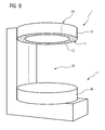
- Fig. 8 shows a further embodiment of an inventive examination device 1 in the form of a magnetic resonance device 40, alternatively, this may also be a computer tomograph.
- this examination device has a cylindrical receiving bore 41, into which the patient is retracted by means of a patient-supporting table, not shown here in detail, which is positioned outside the receiving bore 41 for receiving the patient.
- the examination area 16 is located here in the interior of the receiving bore 41, primarily there in the middle, the area surrounding area 17 is located primarily outside the receiving bore 41, but may also extend somewhat into it.
- a lighting device eleventh arranged, which extends a certain length in the receiving bore 41, but only so far that the image recording, which takes place in the case of a magnetic resonance device using suitable magnetic fields, this is not disturbed.
- the lighting device 11 is placed, for example, on the inner lining 42 of the bore in the upper region or replaced locally. It is bent as a result of the cylindrical shape of the receiving bore 41 and extends in the example shown by a little more than 180 °.
- the light-emitting surface 15 is here directed downwards, ie towards the patient, who is retracted below the light-emitting device 11 or is positioned there or in the illumination area thereof.
- this lighting device 11 By means of this lighting device 11, it is thus possible to illuminate a part of the examination area 16 or of the area environment 17 in front of it homogeneously.
- the structure of the lighting device 11 bent here corresponds to the structure described in the introduction.
- the light sources are preferably arranged on the front or rear, long front edge.
- a second lighting device 11 which is provided on the end face 43 of the magnetic resonance device 40 or otherwise of the computer tomograph.
- the additional or alternative lighting device 11 is here U-shaped and extends in the example shown by approximately 180 ° around the receiving bore 41 around. It also offers the possibility of a large-area light emission via the light emitting surface 15.
- the bulbs can also here, similar to the lighting device 11 off Fig. 1 However, in the area of the inner edge, an outside arrangement is equally conceivable. It can also be any bulbs that emit white or colored light act. Again refer to the previous remarks.
- This second lighting device 11 radiates forward into the surrounding area 17 in front of the examination device 1, where, therefore, the extended patient positioning table etc. is located for patient reception. This offers the possibility of optimally illuminating this area in order to be able to carry out corresponding preparatory actions on the patient, such as, for example, arranging local coils etc.
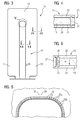
- FIG. 1 shows a further examination device 1 according to the invention in the form of a magnetic resonance device 44, which has two separate magnets 45, 46 arranged horizontally one above the other, between which the examination area 16 and outside of which the area surrounding area 17 is located.
- a lighting device 11 is arranged, which is annular here and rotates around the edge of the magnet 45.
- the light emitting surface is also directed down to the examination area 16, so that this can be optimally and homogeneously illuminated.
- the structure of the lighting device 11 corresponds to the described structure, and here too, the lighting means can preferably be arranged on the inner side edge. Again, they may be white light or colored light emitting LEDs.
- the achievable advantages correspond to the advantages described above, as they can be achieved with all examination devices 1 according to the invention.
- each lighting device 11 no matter what it is now arranged, via suitable connecting means such as screws, quick connector in the form of toggle levers, bayonet, etc.
- suitable connecting means such as screws, quick connector in the form of toggle levers, bayonet, etc.
- corresponding fastening means in the form of retaining rails or brackets etc. may be arranged, which are to be connected with corresponding fastening means on the respective component of the examination device.
- a component may, for example, be a trim piece on which the light-emitting device 11 is placed, or a frame construction, for example of the carriage 37 etc.
- the type and positioning of the light-fixture-side fastening means of course depends on the possibility of attachment to the corresponding component of the examination device.
Abstract
Description
Die Erfindung betrifft eine medizinische Untersuchungsvorrichtung umfassend einen Untersuchungsbereich, in dem eine Untersuchungsperson unter Verwendung einer bildgebenden Einrichtung untersucht wird.The invention relates to a medical examination device comprising an examination area, in which an examination subject is examined using an imaging device.
Derartige Untersuchungsvorrichtungen sind in unterschiedlichen Ausgestaltungen bekannt und dienen unter Verwendung verschiedener, auf jeweils unterschiedlichen Bildaufnahmetechniken basierender bildgebender Einrichtungen dazu, Bilder einer zu untersuchenden Person oder eines bestimmten Bereichs einer Person zu erstellen, die diagnostisch aussagefähig sind. Zu nennen sind beispielsweise Röntgenvorrichtungen umfassend eine Strahlungsquelle und einen Strahlungsempfänger, mittels denen Röntgenbilder aufgenommen werden können, wobei unterschiedliche Typen von Röntgenvorrichtungen, die mitunter auch bestimmten diagnostischen Fragestellungen dienen, bekannt sind. So beispielsweise ein Mammographiegerät, das zur Durchführung von Brustuntersuchungen dient, Röntgenvorrichtungen mit wandseitig angeordneten Detektoren für Aufnahmen einer stehenden Person, C-Bogen-Röntgenvorrichtungen, die häufig an Stativen und deckenseitigen Verfahrenwagen geführt sind, etc. Alternativ zu klassischen Röntgenvorrichtungen sind Computertomographiegeräte bekannt, die ebenfalls mit Röntgenstrahlung arbeiten, jedoch einen üblicherweise zylindrischen Untersuchungsbereich in Form einer Patientenbohrung aufweisen, in die der auf einem Patientenlagerungstisch befindliche Patient eingefahren wird. Um die Bohrung herum kreist eine Röntgenröhre, so dass Durchleuchtungsbilder aus beliebigen Positionen aufgenommen werden können. Bekannt sind ferner Magnetresonanzgeräte, die sich zur Bildaufnahme der Wechselwirkung zwischen einem angelegten Magnetfeld und der Spins der Elektronen der Atomkerne bedienen. Auch hierunter sind Geräte bekannt, die eine im Wesentlichen zylindrische Patientenaufnahme aufweisen, in die der Patient auf einem Tisch liegend eingefahren wird. Bekannt sind aber auch offene Systeme, die zwei vertikal übereinander angeordnete Magneten umfassen, zwischen die der Patient von der Seite her eingefahren werden kann. Die verschiedenen Typen medizinischer Untersuchungsvorrichtungen, deren Aufbau und Funktionsweise sowie deren Anwendungsgebiete sind dem Fachmann hinlänglich bekannt und bedürfen keiner detaillierten Erläuterung.Such examination devices are known in various embodiments and serve to create images of a person to be examined or a specific area of a person who are diagnostically meaningful using different, based on different imaging techniques based imaging devices. For example, X-ray devices comprising a radiation source and a radiation receiver, by means of which X-ray images can be recorded, are known, with different types of X-ray devices, which sometimes also serve specific diagnostic problems, being known. For example, a mammography device, which is used to perform breast examinations, X-ray devices with wall-mounted detectors for taking a standing person, C-arm X-ray devices, which are often performed on tripods and cover-side process car, etc. As an alternative to traditional X-ray devices are known computed tomography devices, the also work with X-rays, but have a usually cylindrical examination area in the form of a patient bore into which the patient located on a patient table is retracted. An X-ray tube revolves around the hole so that fluoroscopic images can be taken from any position. Also known are magnetic resonance devices that use to record the interaction between an applied magnetic field and the spins of the electrons of the atomic nuclei. Also hereunder devices are known which have a substantially cylindrical patient receiving, in which the patient lying on a table is retracted. However, open systems are also known which comprise two magnets arranged vertically one above the other, between which the patient can be moved in from the side. The various types of medical examination devices, their structure and operation and their fields of application are well known to the skilled person and require no detailed explanation.
In nahezu allen Fällen ist es erforderlich, die Untersuchungsperson im Untersuchungsbereich korrekt zu positionieren, um sicherzustellen, dass der zu untersuchende Körperbereich korrekt im Zentrum der bildgebenden Einrichtung positioniert ist. Häufig sind an der Untersuchungsperson selbst vor dem Einbringen in den Untersuchungsbereich oder an der bereits dort befindlichen Untersuchungsperson Handlungen vorzunehmen, beispielsweise Geräte anzuschließen oder sogar kleinere chirurgische Eingriffe wie beispielsweise eine Biopsie zu nehmen oder einen Katheter zu setzen etc. Dies setzt voraus, dass die verantwortliche Person, sei es ein medizinischtechnisches Hilfspersonal oder ein Arzt, den Bereich, in dem sich die Untersuchungsperson befindet und in dem er die Handlung vornehmen will, hinreichend gut einsehen kann. Nachdem medizinische Untersuchungsvorrichtungen häufig in fensterlosen oder abgedunkelten Räumen stehen, was dem Patientenkomfort üblicherweise dienlich ist, bedient man sich regelmäßig deckenseitig angeordneter Leuchten, üblicherweise einfache Punktlichtquellen, die den Raum insgesamt ausleuchten. Über diese Leuchten ist also ein Hintergrundlicht erzeugbar, das auch den Untersuchungsbereich oder das Bereichsumfeld um den Untersuchungsbereich ausleuchten soll. Hierüber wird jedoch häufig nur eine unzureichende Ausleuchtung erreicht, mitunter besteht das Problem, dass die Untersuchungsperson oder die die Untersuchungsperson behandelnde Person selbst Schatten wirft.In almost all cases, it is necessary to correctly position the subject in the examination area to ensure that the body area to be examined is correctly positioned in the center of the imaging device. Often, the examiner himself must perform actions such as attaching devices, or even performing minor surgical procedures such as biopsy or catheterization, prior to insertion into the examination area or to the examiner already there, for example Person, be it a medical technical assistant or a doctor, the area in which the investigator is and in which he wants to perform the action, can see sufficiently well. After medical examination devices are often in windowless or darkened rooms, which is usually convenient for patient comfort, one uses regularly ceiling mounted lights, usually simple point light sources that illuminate the room as a whole. Thus, a background light can be generated via these lights, which should also illuminate the examination area or the area surrounding the examination area. However, this often only insufficient illumination is achieved, sometimes there is the problem that the person under investigation or the person treating the examinee casts shadows himself.
Der Erfindung liegt damit das Problem zugrunde, eine medizinische Untersuchungsvorrichtung anzugeben, bei der eine verbesserte Ausleuchtung des Untersuchungsbereichs und/oder des Bereichsumfelds möglich ist.The invention is therefore based on the problem to provide a medical examination device, in which an improved Illumination of the examination area and / or the area environment is possible.
Zur Lösung dieses Problems ist bei einer medizinischen Untersuchungsvorrichtung der eingangs genannten Art erfindungsgemäß wenigstens eine flächige, über ihre Lichtabstrahlfläche homogenes Licht emittierende Leuchteinrichtung umfassend wenigstens ein Leuchtmittel vorgesehen, mittels der zumindest ein Teil des Untersuchungsbereichs und/oder des Bereichsumfelds ausleuchtbar ist.In order to solve this problem, in a medical examination device of the type mentioned in the introduction, at least one planar light emitting device emitting homogeneous light via its light emitting surface is provided with at least one light source by means of which at least part of the examination area and / or the surrounding area can be illuminated.
Die erfindungsgemäße Untersuchungsvorrichtung zeichnet sich dadurch aus, dass an ihr selbst eine Leuchteinrichtung vorgesehen ist, mittels der gezielt der Untersuchungsbereich und/oder das Bereichsumfeld um den Untersuchungsbereich ausgeleuchtet werden kann. Dabei kommt erfindungsgemäß eine Flächenleuchteinrichtung zum Einsatz, die ihr Licht nicht wie übliche Leuchteinrichtungen punktuell abstrahlt, sondern über eine große Lichtabstrahlfläche verfügt, die entsprechend den gegebenen Möglichkeiten beliebig groß gewählt werden kann. Je nachdem, um welche Art Untersuchungsvorrichtung es sich handelt, kann die Lichtabstrahlfläche bis zu 1 m2 oder mehr betragen, wobei an der erfindungsgemäßen Untersuchungsvorrichtung natürlich auch mehrere derartiger Flächenleuchteinrichtungen vorgesehen sein können, die an unterschiedlichen Positionen angeordnet sind und unterschiedliche Größe aufweisen. In jedem Fall sind sie derart positioniert, dass sie gezielt den Untersuchungsbereich bzw. des Bereichsumfelds beleuchten können, der bzw. das optimal und homogen ausgeleuchtet werden kann, nachdem die Leuchteinrichtung über eine große Lichtabstrahlfläche homogenes Licht emittiert.The examination device according to the invention is characterized in that a lighting device is provided on it itself, by means of which the examination area and / or the area surrounding the examination area can be illuminated in a targeted manner. In this case, according to the invention a surface lighting device is used, which does not emit their light as usual lighting devices selectively, but has a large light emitting surface, which can be chosen arbitrarily large according to the given possibilities. Depending on which type of examination device is concerned, the light emission surface can be up to 1 m 2 or more, whereby of course several such surface illumination devices can be provided on the examination device according to the invention, which are arranged at different positions and have different sizes. In any case, they are positioned in such a way that they can illuminate in a targeted manner the examination area or the area surrounding the area which can be optimally and homogeneously illuminated after the lighting device emits homogeneous light over a large light emission area.
Die großflächige, homogene Ausleuchtung der relevanten Bereiche der Untersuchungsvorrichtung bietet der die Untersuchung durchführenden Person die Möglichkeit, den homogen ausgeleuchteten Bereich optimal einsehen zu können, sei es, dass sie in diesem Bereich arbeitet, um beispielsweise ein Gerät (z.B. eine Spule im Falle eines Magnetresonanzgeräts, den Kompressionsplatte eines Mammographiegeräts etc.) anzubringen oder zu positionieren, sei es lediglich zur kontinuierlichen Kontrolle während der Untersuchung, beispielsweise zur Erfassung etwaiger Patientenbewegungen oder dergleichen. Die homogene Lichtabstrahlung stellt sicher, dass nicht nur eine punktuelle Ausleuchtung gegeben ist, sondern dass ein großes Volumen homogen ausgeleuchtet wird. Insgesamt wird hierüber das Arbeiten an und mit der erfindungsgemäßen Untersuchungsvorrichtung verbessert, etwaige Fehler, die möglicherweise auf eine schlechte Ausleuchtung zurückzuführen sind, können vermieden werden.The large-area, homogeneous illumination of the relevant areas of the examination device offers the person performing the examination the opportunity to optimally view the homogeneously illuminated area, be it working in this area, for example a device (eg a coil in the case of a magnetic resonance device) , the Compression plate of a mammography device, etc.) or to be positioned, be it merely for continuous control during the examination, for example for detecting any patient movements or the like. The homogenous light emission ensures that not only a spot illumination is given, but that a large volume is homogeneously illuminated. Overall, this work on and with the examination device according to the invention is improved, any errors that may be due to poor illumination can be avoided.
Ein weiterer beachtlicher Vorteil der erfindungsgemäßen Untersuchungsvorrichtung ist ferner, dass die flächige, homogene Beleuchtung eine angenehmere Atmosphäre bietet, als die bisher bekannte deckenseitige Raumbeleuchtung, insbesondere, wenn die erfindungsgemäße Flächenleuchteinrichtung auch während der Untersuchung in Betrieb ist. Das heißt, dass hierüber auch der Patientenkomfort verbessert werden kann, verbunden auch hier mit dem Effekt, dass selbstverständlich auch der Patient sich im ausgeleuchteten Untersuchungsbereich oder des Bereichsumfelds infolge der optimalen Beleuchtung desselben wesentlich besser orientieren kann und beispielsweise etwaigen Kommandos der die Untersuchung durchführenden Person, beispielsweise bezüglich der Positionierung, oder etwaigen Bewegungen eines Teils der Untersuchungsvorrichtung etc. wesentlich besser folgen kann.Another considerable advantage of the examination device according to the invention is further that the flat, homogeneous illumination offers a more pleasant atmosphere than the previously known ceiling-sided room lighting, in particular when the surface illumination device according to the invention is also in operation during the investigation. This means that the patient comfort can also be improved here, connected here also with the effect that, of course, the patient can orient himself much better in the illuminated examination area or the area environment due to the optimal illumination and, for example, any commands of the person conducting the examination, For example, with respect to the positioning, or any movements of a part of the examination device etc. can follow much better.
Wie beschrieben kann die Flächengröße der Leuchteinrichtung bzw. deren Lichtabstrahlfläche letztlich beliebig gewählt werden, soweit die Leuchteinrichtung an oder in der Untersuchungsvorrichtung und dort am oder im Untersuchungsbereich oder dem Bereichsumfeld integriert werden kann. Die Leuchteinrichtung ist plattenförmig und je nach Anbringungsort eben oder gebogen ausgebildet. Sie begrenzt zweckmäßigerweise den Untersuchungsbereich oder das Bereichsumfeld zumindest teilweise, so dass sie den Untersuchungsbereich oder das Bereichsumfeld direkt ausleuchten kann. Die Leuchteinrichtung bildet also eine Art Verkleidungsteil, das beispielsweise auf die ohnehin vorgesehene Verkleidung der Untersuchungseinrichtung aufgesetzt bzw. an dieser befestigt wird, oder diese ersetzt. Hierüber ist eine einfache, wirkungsvolle und gleichzeitig optisch ansprechende Integration der Leuchteinrichtung selbst in bereits bekannte Untersuchungsvorrichtungen möglich.As described, the area size of the lighting device or its light emitting surface can ultimately be chosen arbitrarily, as far as the lighting device can be integrated on or in the examination device and there on or in the examination area or the area surrounding. The lighting device is plate-shaped and formed depending on the mounting flat or curved. It expediently limits the examination area or the area surrounding area at least partially so that it can illuminate the examination area or the area surrounding area directly. The lighting device So forms a kind of trim part, which is for example placed on the already provided panel of the examination device or attached to this, or replaced. This is a simple, effective and visually appealing integration of the lighting device even in already known examination devices possible.
Eine erfindungsgemäß verwendbare Flächenleuchteinrichtung weist ein lichtleitendes Flächenelement auf, das wiederum ein Mittel zur Umlenkung von seitlich über das wenigstens eine Leuchtmittel eingekoppelten Lichts zur Abstrahlfläche aufweist. Das lichttransparente Flächenelement ist beispielsweise aus Glas oder vorzugsweise aus Kunststoff, was die Formgebung erleichtert. Als Kunststoff ist beispielsweise PMMA oder PC verwendbar. Das Flächenelement weist, abhängig von seiner gesamten Größe, eine Dicke von wenigen Millimetern, z.B. 5 mm, bis zu wenigen Zentimetern, z.B. 2 cm, auf. Hierüber kann ihm eine hinreichende Eigensteifigkeit verliehen werden, auch wenn das Flächenelement selbst sehr groß ist und eine Fläche von einem oder mehr Quadratmetern belegt. Aus Platzgründen hat es sich als besonders zweckmäßig erwiesen, wenn das Leuchtmittel seitlich, also im Bereich einer Seitenkante, angeordnet ist, und von der Seite her in das lichttransparente, lichtleitende Flächenelement das emittierte Licht einkoppelt. Dieses wird im lichtleitenden Flächenelement primär parallel zur Lichtabstrahlfläche geführt. Über ein entsprechendes Umlenkmittel an dem Flächenelement wird sichergestellt, dass das eingekoppelte Licht reflektiert und zur Lichtabstrahlfläche hin umgelenkt wird, von der es dann austritt. Dieses Umlenkmittel ist so beschaffen, dass die Umlenkung zur Lichtabstrahlfläche hin im gesamten Bereich der Lichtabstrahlfläche erfolgt, bzw. - sofern nur über einen Teil der Lichtabstrahlfläche Licht emittiert werden soll - zumindest in diesem Bereich die Umlenkung erfolgt.A surface illumination device which can be used according to the invention has a light-conducting surface element, which in turn has a means for deflecting light coupled in laterally via the at least one light source to the emission surface. The light-transparent surface element is for example made of glass or preferably of plastic, which facilitates the shaping. For example, PMMA or PC can be used as plastic. The surface element, depending on its overall size, has a thickness of a few millimeters, e.g. 5 mm, up to a few centimeters, e.g. 2 cm, on. This can give it a sufficient inherent rigidity, even if the surface element itself is very large and occupies an area of one or more square meters. For space reasons, it has proved to be particularly useful if the light source is arranged laterally, ie in the region of a side edge, and from the side into the light-transparent, light-conducting surface element couples the emitted light. This is performed in the photoconductive surface element primarily parallel to the light emitting surface. A corresponding deflection means on the surface element ensures that the coupled-in light is reflected and deflected towards the light emission surface, from which it then emerges. This deflecting means is such that the deflection to the light emitting surface takes place in the entire region of the light emitting surface, or - if only about a part of the light emitting surface light is to be emitted - at least in this area, the deflection takes place.
Eine Realisierungsmöglichkeit eines solchen Umlenkmittels ist beispielsweise in Form einer auf einer Seite des Flächenelements aufgebrachten strukturierenden Beschichtung zu sehen. Diese Beschichtung, die beispielsweise in einem Siebdruckverfahren auf das Glas- oder Kunststoffflächenelement aufgebracht wird, bildet eine Vielzahl an Reflexionszentren aus, weist also an der Grenzfläche zum Flächenelement eine Mikrostrukturierung auf, die die Reflexionszentren bildet. Alternativ zum Aufbringen einer solchen Beschichtung ist es auch denkbar, die Oberfläche des Flächenelements selbst zu strukturieren, also in der Oberfläche selbst die Reflexionszentren auszubilden, was beispielsweise durch mechanische, chemische oder physikalische Oberflächenbehandlung möglich ist. Das gezielte Aufbringen oder Ausbilden des Umlenkmittels, sei es über die Beschichtung oder die strukturierte Oberfläche selbst, ermöglicht es des Weiteren, den Bereich der Lichtabstrahlfläche, wo also tatsächlich Licht abgestrahlt werden soll, bzw. die Lichtabstrahlfläche selbst in beliebiger Form zu definieren, unabhängig von der eigentlichen Form des lichtleitenden Flächenelements. Wenn also beispielsweise das lichtleitende Flächenelement aufgrund entsprechender Montageerfordernisse größer auszuführen ist, als die eigentliche Lichtabstrahlfläche, so besteht hierüber die Möglichkeit, das Umlenkmittel auch nur in dem Bereich anzubringen oder auszubilden, wo tatsächlich Licht abgestrahlt werden soll. Auch ist selbstverständlich die Ausbildung entsprechender Abstrahlmuster möglich, indem das Umlenkmittel selbst eine bestimmte geometrische Flächenform belegt etc.One possible realization of such a deflection means is for example in the form of a on one side of the surface element to see applied structuring coating. This coating, which is applied to the glass or plastic surface element, for example in a screen printing process, forms a multiplicity of reflection centers, that is to say that at the interface with the surface element it has a microstructure which forms the reflection centers. As an alternative to applying such a coating, it is also conceivable to structure the surface of the surface element itself, ie to form the reflection centers in the surface itself, which is possible for example by mechanical, chemical or physical surface treatment. The targeted application or formation of the deflecting means, be it via the coating or the structured surface itself, furthermore makes it possible to define the region of the light emitting surface, where in fact light is to be emitted, or the light emitting surface itself in any desired form, independently of the actual shape of the photoconductive surface element. If, for example, the light-guiding surface element is to be made larger than the actual light-emitting surface due to corresponding installation requirements, then there is the possibility of attaching or forming the deflection means only in the region where light is actually to be emitted. Of course, the formation of corresponding radiation pattern is possible by the deflection itself occupies a certain geometric surface shape, etc.
Um die Homogenität der Lichtabstrahlung noch weiter zu verbessern, weist das Flächenelement ferner an der Seite der Lichtabstrahlfläche einen Diffusor auf bzw. ist ihm ein solcher Diffusor zugeordnet. Ein solcher Diffusor ist zweckmäßigerweise ebenfalls als flächiges, plattenförmiges Element ausgebildet, das wie auch das lichtleitende Flächenelement eben oder gebogen ausgeführt ist. Denkbar ist hier beispielsweise die Verwendung einer sattinierten Glas- oder Kunststoffscheibe, die auf das Glas- oder Kunststoffflächenelement aufgesetzt wird. Auch dieses flächige Diffusorbauteil weist eine geringe Dicke von nur wenigen Millimetern auf, z.B. 2 - 10 mm. An der gegenüberliegenden Seite des Flächenelements ist zweckmäßigerweise eine Rückwand angeordnet, die die Leuchteinrichtung nach hinten hin abschießt.In order to further improve the homogeneity of the light emission, the surface element also has a diffuser on the side of the light emission surface or is associated with such a diffuser. Such a diffuser is expediently also designed as a flat, plate-shaped element which, like the light-conducting surface element, is flat or curved. It is conceivable here, for example, the use of a satined glass or plastic disc, which is placed on the glass or plastic surface element. This flat diffuser component has a small thickness of only a few millimeters, for example 2 - 10 mm. On the opposite side of the surface element, a rear wall is expediently arranged, which shoots the lighting device towards the rear.
Eine besonders zweckmäßige Weiterbildung der Erfindung sieht entlang der Seite mehrere Leuchtmittel zum Einkoppeln von Licht in das Flächenelement vor. Insbesondere bei relativ großflächigen Flächenelementen und mithin langen Seitenkanten und großer Lichtabstrahlfläche bietet sich so die Möglichkeit, eine Vielzahl kantenseitiger Lichterzeugungszentren und Lichteinkoppelpunkte zu realisieren. Neben der Möglichkeit, infolge der seitlichen Anordnung die Leuchteinheit insgesamt sehr schmal aufzubauen, bietet die Verwendung und Anordnung mehrerer seitlicher Leuchtmittel die Möglichkeit, auch eine große Lichtmenge in das Flächenelement einkoppeln zu können. Die Leuchtmittel selbst sind zweckmäßigerweise in einer bandartigen Einheit zusammengefasst, die entlang der Flächenelementseitenkante verlegt und dort entsprechend fixiert bzw. gekapselt angeordnet ist.A particularly expedient development of the invention provides several light sources for coupling light into the surface element along the side. In particular, with relatively large surface area elements and thus long side edges and large light emitting surface thus offers the opportunity to realize a variety of edge-side light generation centers and Lichteinkoppelpunkte. In addition to the possibility of constructing the light unit as a whole very narrow due to the lateral arrangement, the use and arrangement of several lateral bulbs offers the possibility to couple a large amount of light in the surface element can. The light sources themselves are expediently combined in a band-like unit which is laid along the surface element side edge and is correspondingly fixed or encapsulated there.
Wenngleich grundsätzlich Leuchtmittel in Form von Glüh- oder Halogenleuchtkörpern verwendet werden können, sieht eine zweckmäßige Erfindungsausgestaltung den Einsatz von LEDs vor. Diese sind sehr klein, können also ohne weiteres auch im Bereich schmaler Flächenelementseitenkanten angeordnet werden, bieten aber gleichzeitig eine sehr hohe Lichtausbeute. Ihr Betrieb ist energetisch günstig, die Lebensdauer ist lang, sie zeigen kaum Wärmeentwicklung. Auch ist es ohne weiteres möglich, auf sehr kleinem Raum viele LEDs integrieren zu können.Although basically bulbs in the form of incandescent or halogen bulbs can be used, provides a useful embodiment of the invention before the use of LEDs. These are very small, so they can be readily arranged in the area of narrow surface element side edges, but at the same time offer a very high light output. Their operation is energetically favorable, the service life is long, they show little heat development. It is also easily possible to integrate many LEDs in a very small space.
Wie bereits beschrieben, werden das oder die Leuchtmittel im montierten Zustand zweckmäßigerweise gekapselt, so dass sie sicher fixiert sind. Zweckmäßigerweise wird weiterhin an der Leuchteinrichtung im Bereich der Lichtabstrahlfläche ein das oder die Leuchtmittel verdeckendes nicht transparentes Abdeckelement angeordnet, das zumindest so groß ist, dass es von der Lichtabstrahlfläche her gesehen die Leuchtmittel überdeckt. Hierüber wird verhindert, dass eine Person von der Lichtabstrahlfläche her unmittelbar auf ein im Betrieb mitunter sehr helles Leuchtmittel blicken kann. Ein solches nicht transparentes Abdeckelement kann beispielsweise eine auch optisch ansprechende Metallplatte oder -schiene sein, die im Bereich der Seitenkante angeordnet ist bzw. umläuft. Auch Abdeckelemente aus Kunststoff sind selbstverständlich denkbar.As already described, the one or more bulbs are suitably encapsulated in the mounted state, so that they are securely fixed. Expediently, furthermore, a non-transparent cover element which conceals the illuminant or means is arranged at the luminous device in the region of the light emission surface, which is at least large enough for the luminous means to be seen from the light emission surface covered. This prevents a person from the light emission surface can look directly at a very bright light bulbs during operation. Such a non-transparent cover element may, for example, be a visually appealing metal plate or rail, which is arranged or circumscribes in the region of the side edge. Also, plastic cover elements are of course conceivable.
Die Leuchteinrichtung selbst umfasst des Weiteren eine Steuerungseinrichtung, über welche die Helligkeit des oder der Leuchtmittel, insbesondere der LEDs veränderbar ist. Die Helligkeit und damit die über die Lichtabstrahlfläche abgestrahlte Lichtmenge kann demgemäß über die Steuerungseinrichtung, die bei Verwendung mehrerer Leuchtmittel diese entweder gemeinsam oder auch separat ansteuern und mithin anschalten kann, je nach Bedarf und Situation anpassen bzw. verändern. Wird beispielsweise zum Positionieren des Patienten oder zum Anschließen oder Anbringen von Geräten oder zur Durchführung chirurgischer Eingriffe etc. eine hohe Helligkeit benötigt, so wird beispielsweise während der Untersuchung, also der Bildaufnahme, die mithin über mehrere Minuten bis Stunden gehen kann, eine reduzierte Helligkeit als ausreichend erachtet. Dies kann über die Steuerungseinrichtung ohne weiteres gesteuert werden, beispielsweise indem die Helligkeit über die Steuerungseinrichtung zwischen diskreten Helligkeitsstufen schaltbar ist, oder stufenlos zwischen einem Maximalwert und einem Minimalwert gedimmt werden kann. Hierüber ist also eine beliebige Veränderung der Helligkeit möglich, was auch die Möglichkeit bietet, bei Bedarf und insbesondere langer Untersuchungsdauer eine den Patientenkomfort hebende ansprechende Atmosphäre zu erzeugen.The lighting device itself further comprises a control device, via which the brightness of the one or more light sources, in particular of the LEDs is variable. The brightness and thus the amount of light emitted via the light emitting surface can accordingly be adjusted or changed by the control device which, when using a plurality of light sources, can actuate them either together or separately and thus switch them on, depending on the requirements and situation. If, for example, a high brightness is required for positioning the patient or for connecting or attaching devices or performing surgical interventions, for example, during the examination, ie the image acquisition, which can therefore take several minutes to hours, a reduced brightness is used as sufficient. This can be readily controlled by the control device, for example by the brightness can be switched between discrete brightness levels via the control device, or can be dimmed continuously between a maximum value and a minimum value. In this way, any change in brightness is possible, which also offers the possibility to generate an appealing atmosphere that enhances patient comfort when needed and in particular over a long period of investigation.
Eine besonders zweckmäßige Erfindungsausgestaltung sieht ferner vor, mittels der Leuchteinrichtung weißes Licht und Licht wenigstens einer Farbe emittieren zu können. Das heißt, dass bei Bedarf von einer weißen Beleuchtung auf eine Farbbeleuchtung über die Steuerungseinrichtung umgeschaltet werden kann. Dies bietet die Möglichkeit, der Untersuchungsperson Informationen zu vermitteln, beispielsweise dahingehend, dass während der Bildaufnahme von weißer Beleuchtung auf Farbbeleuchtung umgeschaltet wird, so dass die Untersuchungsperson genau weiß, wann die Bildaufnahme beginnt. Am Ende derselben kann wieder von der Farbbeleuchtung auf die weiße Beleuchtung umgeschaltet werden, so dass hierüber das Ende der Bildaufnahme mitgeteilt werden kann. Denkbar ist es auch, hierüber Zeiträume anzuzeigen, innerhalb welcher der Patient sich beispielsweise nicht bewegen darf oder die Luft anhalten muss oder bestimmte Bewegungen durchführen muss, wenn dies eine bestimmte Bildaufnahme, beispielsweise im Bereich der Magnetresonanzbildgebung, erfordert. Wenn also der Patient beispielsweise die Luft anhalten soll, wird ihm dies durch Umschalten auf Farblicht angezeigt, das so lange zugeschaltet bleibt, bis der Luftanhaltezeitraum verstrichen ist und wieder auf Weißlicht umgeschaltet werden kann. Hierüber kann auf sehr einfache und intuitive Weise eine Information vermittelt werden. Denkbar ist beispielsweise ein Umschalten auf Rotlicht, da der Mensch mit rotem Licht häufig eine Informationsvermittlung verbindet.A particularly expedient embodiment of the invention also provides that it is possible to emit white light and light of at least one color by means of the lighting device. That is, if necessary, it is possible to switch from a white illumination to a color illumination via the control device. This provides the opportunity to the investigator information to convey, for example, that during the image acquisition of white lighting is switched to color lighting, so that the examiner knows exactly when the image acquisition begins. At the end of the same can be switched back from the color illumination to the white illumination, so that hereby the end of the image acquisition can be communicated. It is also conceivable to indicate periods of time within which the patient is not allowed to move or has to stop the air or has to perform certain movements, if this requires a specific image acquisition, for example in the field of magnetic resonance imaging. For example, if the patient is to stop the air, this is indicated to him by switching to colored light, which remains switched on until the air suspension period has elapsed and can be switched back to white light. This information can be conveyed in a very simple and intuitive way. It is conceivable, for example, to switch to red light, since humans often associate information with red light.
Hierüber ist es aber auch ohne weiteres möglich, den Patientenkomfort zu verbessern und die Beleuchtungsatmosphäre zu beeinflussen, was insbesondere dann von Vorteil ist, wenn es sich um lang dauernde Untersuchungen handelt. Denn es besteht dann die Möglichkeit, unter Abschalten der hellen Weißlichtbeleuchtung auf eine angenehme Farbausleuchtung zu wechseln, die vom Patienten grundsätzlich als angenehm empfunden wird und so sein Wohlbefinden während der Untersuchungsdauer fördert. Auch hat farbiges Licht mitunter einen therapeutischen Effekt, mitunter unterstützt und fördert es etwaige Heilungsprozesse, so dass auch diesbezüglich die Vorteile einer Farbveränderbarkeit genutzt werden können. Natürlich besteht auch hier die Möglichkeit, je nach Ausgestaltung der Leuchtmittel, von weißem Licht auf Farblicht stufenlos zu wechseln, beispielsweise das Weißlicht herunterzudimmen und das Farblicht heraufzudimmen, gleichwie auch eine scharfe Umschaltung von Weiß- auf Farblicht möglich ist.However, it is also readily possible to improve patient comfort and to influence the lighting atmosphere, which is particularly advantageous when dealing with long-lasting examinations. Because there is then the possibility of switching off the bright white light illumination to a pleasant color illumination, which is generally perceived by the patient as pleasant and thus promotes his well-being during the study period. Also, colored light sometimes has a therapeutic effect, sometimes supports and promotes any healing processes, so that in this regard, the benefits of a Farbveränderbarkeit can be used. Of course, here too it is possible, depending on the design of the bulbs, to change steplessly from white light to colored light, for example to dim the white light and to increase the color light, just as a sharp changeover from white to colored light is possible.
Grundsätzlich besteht die Möglichkeit, weißes und farbiges Licht jeweils über die gesamte Lichtabstrahlfläche zu emittieren, mithin also für die unterschiedlichen Farbausleuchtungen stets die gesamte Lichtabstrahlfläche zu nutzen. Alternativ ist es auch denkbar, weißes und farbiges Licht in voneinander getrennten Bereichen der Lichtabstrahlfläche abzustrahlen. Dies ist vor allem dann zweckmäßig, wenn hierüber Informationen vermittelt werden sollen. Denn in diesem Fall ist es möglich, an der Lichtabstrahlfläche in einem bestimmten Bereich über die Farblichtbeleuchtung quasi eine Art "Informationsleuchte" zu realisieren.In principle, it is possible to emit white and colored light in each case over the entire light emitting surface, and therefore always to use the entire light emitting surface for the different color illuminations. Alternatively, it is also conceivable to emit white and colored light in separate regions of the light emitting surface. This is particularly useful if this information should be conveyed. Because in this case, it is possible to realize on the light emitting surface in a certain area on the color light lighting quasi a kind of "information light".
Eine erste Erfindungsalternative sieht vor, den jeweiligen Leuchtfarben dezidierte Leuchtmittel zuzuordnen. Die mehrere Leuchtmittel umfassende Leuchteinrichtung umfasst also neben wenigstens einem weißes Licht emittierenden Leuchtmittel wenigstens ein farbiges Licht emittierendes Leuchtmittel, das separat ansteuerbar ist.A first alternative of the invention provides for allocating dedicated illuminants to the respective luminous colors. The light-emitting means comprising a plurality of lighting means thus comprises, in addition to at least one illuminating means emitting white light, at least one illuminating means emitting colored light which can be activated separately.
Alternativ dazu besteht die Möglichkeit, weißes Licht sowie beliebige Mischfarben des abgestrahlten Lichts durch Lichtmischung zu erzeugen. Zu diesem Zweck kann wenigstens ein rotes Licht, wenigstens ein blaues Licht und wenigstens ein grünes Licht emittierendes Leuchtmittel vorgesehen sein, die separat ansteuerbar sind. Je nachdem, welche Leuchtmittel zugeschaltet sind und mit welcher Intensität sie betrieben werden, kann weißes Licht oder eine beliebige andere Mischfarbe erzeugt werden. Zweckmäßigerweise kommen in allen Fällen LEDs zum Einsatz, also sowohl weiße als auch farbige LEDs. Handelt es sich um eine hinreichend große Leuchteinrichtung bzw. ein hinreichend großes lichttransparentes Flächenelement, so kommen von jeder Farbe selbstverständlich eine Vielzahl einzelner Leuchtmittel bzw. LEDs zum Einsatz, wobei jeweils drei LEDs der unterschiedlichen Farben zu Gruppen zusammengefasst und benachbart angeordnet sind. Die abgestrahlte Lichtfarbe ist bei dieser Erfindungsalternative zweckmäßigerweise ebenfalls stufenlos veränderbar, um einen sanften Übergang zu jeder beliebigen Farbe zu gewährleisten.Alternatively, it is possible to produce white light and any mixed colors of the emitted light by light mixing. For this purpose, at least one red light, at least one blue light and at least one green light emitting light source can be provided, which are separately controllable. Depending on which lamps are switched on and with what intensity they are operated, white light or any other mixed color can be generated. Conveniently, LEDs are used in all cases, so both white and colored LEDs. If it is a sufficiently large lighting device or a sufficiently large light-transparent surface element, of course, a variety of individual lamps or LEDs are used by each color, in each case three LEDs of different colors are combined into groups and arranged adjacent. The radiated light color is expediently also in this invention alternative infinitely variable to ensure a smooth transition to any color.
Neben dem Umstand, auch hierüber Informationen vermitteln zu können, bietet diese Erfindungsausgestaltung die Möglichkeit, beliebige Farbausleuchtungen und damit Lichtatmosphären zu schaffen. Dies kann sogar so weit gehen, dass die Untersuchungsperson insbesondere bei länger dauernden Untersuchungen eine gewünschte Farbe wählen kann, die während der Untersuchung abgestrahlt werden soll, bei der sie sich also am wohlsten fühlt. Für die untersuchende Person besteht trotz Farbausleuchtungen nach wie vor die Möglichkeit, den Patienten zu beobachten, nachdem auch die Farbausleuchtung stets den Untersuchungsbereich und/oder dessen Bereichsumfeld erfasst. Ein kontinuierlicher Farbwechsel ist hiermit ebenfalls möglich, z. B. um den Patientenkomfort bei lang dauernden Untersuchungen zu fördern. Hierbei findet dauernd ein Farbwechsel statt, wobei stetig von einer Farbe auf eine andere gewechselt wird. Vom Patienten wird ein solches Lichtspiel als angenehm und beruhigend empfunden.In addition to being able to convey information about this, this embodiment of the invention offers the possibility of creating any desired color illumination and thus light atmospheres. This can even go so far that the examiner can choose a desired color, especially during longer-term examinations, which should be emitted during the examination, which makes her feel most comfortable. Despite the color illumination, it is still possible for the examiner to observe the patient, even after the color illumination always covers the examination area and / or the area surrounding it. A continuous color change is hereby also possible, for. B. to promote patient comfort in long-lasting examinations. Here, a color change takes place constantly, being constantly changed from one color to another. From the patient, such a play of light is perceived as pleasant and calming.
Wie bereits beschrieben besteht über die Emission von Farbe grundsätzlich die Möglichkeit, dem Untersuchungspatienten Informationen vermitteln zu können. Um die Informationstiefe noch weiter zu erhöhen, sieht eine zweckmäßige Erfindungsausgestaltung vor, an oder in der Leuchteinrichtung wenigstens ein der Darstellung von Informationen und/oder Bildern dienendes Display anzuordnen, oder der Leuchteinrichtung ein solches Display zuzuordnen. Grundsätzlich besteht die Möglichkeit, in einem ausgezeichneten Bereich der Leuchteinrichtung ein entsprechendes Display zu integrieren, wozu beispielsweise ein entsprechender Ausschnitt in dem Flächenelement und dem davor gesetzten Diffusor respektive auch der Rückwand vorgesehen wird, in der ein solches Display integriert wird. Hierüber können dem Patienten beliebige Informationen dargestellt werden, beispielsweise wie lange die Untersuchung bereits dauert oder noch dauern wird, etwaige Handlungsanweisungen wie beispielsweise die Luft anzuhalten etc., oder Informationen für die zur Untersuchung durchführende Person wie beispielsweise im Falle eines Mammographiegeräts über die auf die Brust ausgeübte Kompressionskraft, die Kompressionsdichte, den Aufnahmewinkel oder allgemeine Patientendaten. Alternativ oder zusätzlich zu einem solchen Display ist es auch möglich, wenigstens eine Projektionseinrichtung vorzusehen, mittels der Informationen und/oder Bilder auf einen Bereich der Lichtabstrahlfläche der Leuchteinrichtung projizierbar sind. Hier kommt also ein separates Projektionsgerät zum Einsatz, das entsprechende Informationen/Bilder auf die Leuchteinrichtung strahlt.As already described, the emission of color basically offers the possibility of being able to convey information to the examination patient. In order to further increase the depth of information, an expedient embodiment of the invention provides for arranging at least one display serving information and / or images on or in the lighting device or assigning such a display to the lighting device. In principle, there is the possibility of integrating a corresponding display in an excellent region of the lighting device, for which purpose, for example, a corresponding cutout is provided in the surface element and the diffuser or the rear wall placed in front, in which such a display is integrated. This information can be presented to the patient, for example, how long the investigation already takes or will take to stop any instructions such as the air etc., or information for the person performing the examination, such as in the case of a mammography device on the compression force applied to the chest, the compression density, the angle of admission or general patient data. As an alternative or in addition to such a display, it is also possible to provide at least one projection device by means of which information and / or images can be projected onto a region of the light emission surface of the lighting device. So here comes a separate projection device used, which radiates appropriate information / images on the lighting device.
Über die Farblichterzeugung besteht nicht nur die Möglichkeit, Informationen zu vermitteln oder eine angenehme Untersuchungsatmosphäre zu schaffen, sondern auch die Möglichkeit, durch Farbwechsel visuelle Reize zu geben, wie sie beispielsweise im Rahmen einer funktionellen Bildgebung, insbesondere bei Magnetresonanz- oder Computertomographieaufnahmen, mitunter erforderlich sind. Wird von Weißlicht beispielsweise auf grelles Rotlicht umgeschalten, so werden bestimmte Aktivitäten im Gehirn angeregt, die über die funktionelle Bildgebung erkannt werden können. Über die Darstellung von beliebigen Informationen über ein Display oder mittels einer Projektionseinrichtung ist es ferner möglich, andere optische Reize, die andere Gehirnzentren anregen, beispielsweise beim Lesen oder dergleichen, gezielt zu geben.Color light generation not only provides the opportunity to convey information or to create a pleasant atmosphere of investigation, but also to provide visual stimulation through color change, as is sometimes required in the context of functional imaging, in particular in magnetic resonance or computed tomography scans , Switching from white light to bright red light, for example, stimulates certain brain activities that can be detected through functional imaging. On the display of any information via a display or by means of a projection device, it is also possible, other optical stimuli that stimulate other brain centers, for example, when reading or the like to give targeted.
Wie beschrieben kann es sich bei der Untersuchungseinrichtung um eine Röntgeneinrichtung handeln, beispielsweise eine solche, die einer Untersuchung einer stehenden Untersuchungsperson dient, wobei in diesem Fall die Leuchteinrichtung vertikal stehend angeordnet ist. Ein solches Gerät kann beispielsweise ein Mammographiegerät sein, wobei die Leuchteinrichtung hinter dem an einer Vertikalsäule vertikal bewegbar angeordneten Röntgenbildaufnahmemittel angeordnet ist. Bei einem Mammographiegerät sind bekanntlich die Röntgenröhre und der Detektor, üblicherweise ein digitaler Flachdetektor, in einem festen Abstand zueinander über eine geeignete Bewegungsmechanik an einer Vertikalsäule bewegbar. Vor dieser Vertikalsäule, diese quasi nach vorne hin verkleidend, ist nun erfindungsgemäß die Leuchteinrichtung angeordnet. Die Leuchteinrichtung, hier eine ebene Platte, schaut je nach Ausgestaltung zur Seite bzw. oberhalb des Röntgenbildaufnahmemittels hervor, so dass der vor der Leuchteinrichtung befindliche Raum, das Umfeld des Untersuchungsbereichs, wie auch der Untersuchungsbereich zwischen Röntgenröhre und Detektor hierüber teilweise oder vollständig ausgeleuchtet werden können. Die Patientin steht vor dem Röntgenbildaufnahmemittel und damit vor der Leuchteinrichtung, blickt also in Richtung der beleuchteten Leuchteinrichtung. Die die Untersuchung vornehmende Person kann von der Seite her an das Röntgenbildaufnahmemittel herantreten, kann also mithin den Untersuchungsbereich optimal einsehen, und die Patientin positionieren, wie auch die Kompressionseinheit, über die die Brust komprimiert wird, bedienen. Der bzw. die relevanten Bereiche sind über die flächige Leuchteinrichtung optimal ausgeleuchtet, wie der Patientin auch ein lichttechnisch angenehmes Umfeld geboten wird, insbesondere wenn im Falle der Untersuchung die Leuchthelligkeit zurückgenommen oder auf eine andere Farbe umgeschaltet wird.As described, the examination device may be an X-ray device, for example one which is used to examine a standing examination subject, in which case the lighting device is arranged vertically. Such a device may for example be a mammography device, wherein the lighting device is arranged behind the on a vertical column vertically movable arranged X-ray image pickup means. In a mammography apparatus, it is known that the x-ray tube and the detector, usually a digital flat detector, are at a fixed distance from one another via a suitable movement mechanism movable on a vertical column. In front of this vertical column, this virtually disguised towards the front, the lighting device is now arranged according to the invention. Depending on the embodiment, the lighting device, in this case a flat plate, projects to the side or above the X-ray image recording means, so that the area in front of the lighting device, the surroundings of the examination area, as well as the examination area between X-ray tube and detector can be partially or completely illuminated , The patient stands in front of the X-ray image recording means and thus in front of the lighting device, thus looking in the direction of the illuminated lighting device. The examining person can approach from the side of the X-ray image recording means, so therefore can optimally view the examination area, and position the patient, as well as the compression unit over which the breast is compressed, operate. The relevant areas are optimally illuminated via the areal lighting device, as the patient is also provided with an optically pleasing lighting environment, in particular if, in the case of the examination, the luminous brightness is withdrawn or changed over to another color.
Während bei einem Mammographiegerät Röhre und Detektor gemeinsam zur Aufnahme vertikaler Durchleuchtungsbilder vertikal bewegt werden können, sind bei anderen Röntgengeräten horizontale Bildaufnahmen möglich. Häufig ist der Detektor vertikal beweglich an einer Vertikalsäule geführt, um ihn in unterschiedliche Positionen relativ zum davor stehenden Patienten positionieren zu können. Die Röntgenröhre befindet sich an einem Boden- oder Deckenstativ und kann unabhängig vom Detektor bewegt werden. Mit solchen Röntgengeräten sind beispielsweise Thoraxaufnahmen oder dergleichen möglich. Auch bei solchen Geräten ist nun die Integration einer erfindungsgemäßen Flächenleuchteinrichtung möglich, auch hier ist sie hinter dem Detektor und vor der Vertikalsäule angeordnet, verkleidet mithin also wiederum die Vertikalsäule und strahlt unmittelbar in den Untersuchungsbereich bzw. das Bereichsumfeld nach vorne hin ab.While in a mammography device tube and detector can be moved vertically together to record vertical fluoroscopy images, other X-ray devices horizontal imaging is possible. Frequently, the detector is guided vertically movable on a vertical column in order to position it in different positions relative to the patient standing in front. The X-ray tube is located on a floor or ceiling stand and can be moved independently of the detector. With such X-ray devices, for example, thorax images or the like are possible. Even with such devices, the integration of a surface lighting device according to the invention is now possible, here too, it is located behind the detector and in front of the vertical column, so in turn disguised the vertical column and radiates directly into the examination area or the area surrounding the front.
In allen Fällen, in denen ein Teil des Röntgenbildaufnahmemittels oder das gesamte Röntgenbildaufnahmemittel vertikal bewegbar an einer Säule geführt ist, bietet sich die Anordnung der Leuchteinrichtung zwischen Säule und beweglichem Bildaufnahmeteil an. Die Leuchteinrichtung weist hierfür zweckmäßigerweise eine U-Form auf, wobei ein das Röntgenbildaufnahmemittel oder den Detektor tragender und an der Vertikalsäule geführter Tragarm zwischen den beiden U-Schenkeln durchgreift. Die Leuchteinrichtung ist hier also ein einteiliges Bauteil, das quasi nach Art eines Rahmens die Röntgeneinrichtung umläuft und von dem Tragarm, der die Verbindung zwischen Bildaufnahmemittel/Detektor und Vertikalsäule bietet, durchgriffen ist. Hierüber wird sichergestellt, dass eine sehr große Lichtabstrahlfläche gegeben ist, bei gleichzeitig vorteilhafter Integration der Leuchteinrichtung, die darüber hinaus auch eine Nachrüstmöglichkeit für bestehende Gerätschaften bietet.In all cases in which a part of the X-ray image recording means or the entire X-ray image recording means is vertically movably guided on a column, the arrangement of the lighting device between the column and the movable image recording part is suitable. For this purpose, the light-emitting device expediently has a U-shape, wherein a support arm carrying the X-ray image recording means or the detector and guided on the vertical column passes through between the two U-legs. The lighting device here is thus a one-piece component, which circulates the X-ray device virtually in the manner of a frame and is penetrated by the support arm, which provides the connection between image recording means / detector and vertical column. This ensures that a very large light emitting surface is given, with simultaneous advantageous integration of the lighting device, which also offers a retrofit option for existing equipment.
Ein weiterer Typ von Röntgeneinrichtungen zeichnet sich dadurch aus, dass das Röntgenbildaufnahmemittel an einem Stativ, das an einem an deckenseitig angeordneten Führungsmitteln bewegbar geführten Wagen angeordnet ist, angeordnet ist, und ein Lagerungstisch für das Untersuchungsobjekt vorgesehen ist, wobei die Leuchteinrichtung an dem Wagen angeordnet ist. Hierbei handelt es sich um ein deckengeführtes Gerät, beispielsweise mit einem C-Bogen, an dem die Röntgenröhre und der Detektor angeordnet sind, oder zwei am Führungswagen angeordneten separaten Stativen, von denen eines die Röhre und das andere den Detektor trägt. Bei dieser Erfindungsausgestaltung ist die Leuchteinrichtung am Wagen angeordnet, der in der Regel relativ großflächig ist, nachdem er eine x-y-Führung an den deckenseitigen Führungsmitteln ermöglicht. Die Form der Leuchteinrichtung ist abhängig von der Wagenform, kann also beispielsweise viereckig oder rechteckig sein, denkbar auch rund, je nachdem, wie der Wagen ausgestaltet ist. Auch hier ist die Verwendung einer großflächigen Leuchteinrichtung möglich, die von oben direkt auf den Untersuchungsbereich, hier den Lagerungstisch mit dem Patienten, strahlt.Another type of X-ray equipment is characterized in that the X-ray image pickup means is arranged on a stand which is arranged on a carriage movably guided on cover-side guide means, and a storage table for the object to be examined is provided, wherein the lighting device is arranged on the carriage , This is a ceiling-mounted device, for example, with a C-arm, on which the X-ray tube and the detector are arranged, or two arranged on the carriage separate tripods, one of which carries the tube and the other the detector. In this embodiment of the invention, the lighting device is arranged on the carriage, which is usually relatively large area, after allowing an xy-guide on the ceiling-side guide means. The shape of the lighting device is dependent on the carriage shape, so it may for example be square or rectangular, conceivable also round, depending on how the car designed is. Again, the use of a large-scale lighting device is possible, which radiates from above directly to the examination area, here the storage table with the patient.
Ein anderer Typ einer Untersuchungseinrichtung ist wie beschrieben eine Magnetresonanzeinrichtung oder eine Computertomographieeinrichtung. Beide weisen zumeist eine im Wesentlichen zylindrische Aufnahmebohrung für die Untersuchungsperson auf, wobei die Leuchteinrichtung diese zumindest über einen Teil ihrer Länge und zumindest über einen Teil ihres Umfangs auskleidet. Hier ist die Leuchteinrichtung in das Innere der Aufnahmebohrung integriert, vornehmlich im Bereich des Randes der Aufnahmebohrung und bevorzugt an der Seite, an der der Patientenlagerungstisch eingefahren wird. In diesem Bereich ist die Integration der Leuchteinrichtung unkritisch, als die bildgebenden Magnetfelder mehr im Bereich der Bohrungsmitte erzeugt werden. Gleichwohl kann die gesamte Aufnahmebohrung als Untersuchungsbereich angesprochen werden bzw. der Bohrungseingang als Untersuchungsbereichsumfeld, in dem unter Verwendung der Leuchteinrichtung die erfindungsgemäße homogene Flächenausleuchtung möglich ist. Die Leuchteinrichtung ist hier infolge der Zylinderform der Aufnahmebohrung gebogen, sie kann sich beispielsweise über eine Länge von 30 oder 40 cm in das Bohrungsinnere erstrecken und beispielsweise um 180° bei Anordnung an der oberen Zylinderwand in der Mitte erstrecken, auch ein weiterer Umfangsumlauf ist möglich. Üblicherweise befindet sich in diesem Bereich der Kopf des Patienten, der dann beispielsweise Farbinformationen oder dergleichen vermittelt bekommen kann, verbunden mit der optimalen Ausleuchtung dieses Bereichs für die die Untersuchung durchführende Person. Auch kann eine entsprechende Farblichtatmosphäre oder Helligkeitsveränderung erzeugt bzw. vorgenommen werden, je nach Ausgestaltung der Leuchteinrichtung und Bedarf.Another type of examination device is as described a magnetic resonance device or a computed tomography device. Both usually have a substantially cylindrical receiving bore for the examination subject, wherein the lighting device lining these at least over part of their length and at least over part of their circumference. Here, the lighting device is integrated into the interior of the receiving bore, especially in the region of the edge of the receiving bore and preferably on the side at which the patient table is retracted. In this area, the integration of the lighting device is not critical, as the magnetic fields are generated more in the middle of the bore. Nevertheless, the entire receiving bore can be addressed as an examination area or the bore entrance as an examination area environment in which the homogeneous surface illumination according to the invention is possible using the lighting device. The lighting device is bent here as a result of the cylindrical shape of the receiving bore, it may extend for example over a length of 30 or 40 cm in the bore interior and extend for example by 180 ° when arranged on the upper cylinder wall in the middle, also a circumferential circulation is possible. Usually in this area is the head of the patient, who can then be given color information or the like, for example, associated with the optimal illumination of this area for the person conducting the examination. Also, a corresponding color light atmosphere or brightness change can be generated or made, depending on the design of the lighting device and needs.
Alternativ oder zusätzlich zur Anordnung der Leuchteinrichtung in der Aufnahmebohrung ist es auch denkbar, bei einem Gerät mit einer solchen zylindrischen Aufnahmebohrung die Leuchteinrichtung an der Geräteaußenseite, hier der Stirnseite, von welcher Seite her der Patientenlagerungstisch mit dem Patienten in der Aufnahmebohrung eingefahren wird, anzuordnen, wobei die Leuchteinrichtung zumindest einen Teil der im Wesentlichen ringförmigen Stirnseite benachbart zur Aufnahmebohrung belegt. Über diese Leuchteinrichtung wird das Umfeld vor dem Aufnahmebereich, hier also vor der Untersuchungseinrichtung selbst, ausgeleuchtet. Die Leuchteinrichtung kann beispielsweise als Halbring ausgeführt sein und nur um die obere Hälfte laufen, oder sich weiter herum erstrecken. Über diese Leuchteinrichtung kann der Bereich vor der Bohrung mit ausgefahrenem Tisch sehr gut ausgeleuchtet werden, so dass die die Untersuchung durchführende Person beim Aufbringen des Patienten auf den Tisch und Setzen etwaiger Lokalspulen etc. dies in einem optimalen homogen ausgeleuchteten Umfeld vornehmen kann.Alternatively or in addition to the arrangement of the lighting device in the receiving bore, it is also conceivable in a Device with such a cylindrical receiving bore, the lighting device on the outside of the device, here the front side, from which side of the patient support table is retracted with the patient in the receiving bore to arrange, wherein the lighting device occupies at least a portion of the substantially annular face adjacent to the receiving bore. About this lighting device, the environment in front of the recording area, ie here before the examination device itself, illuminated. The lighting device may for example be designed as a half ring and only run around the upper half, or continue to extend around. About this lighting device, the area can be very well illuminated before the hole with the table extended, so that the person performing the investigation when placing the patient on the table and setting any local coils, etc. this can make in an optimal homogeneously illuminated environment.
Eine Alternativausführung einer Magnetresonanzeinrichtung sieht anstelle einer zylindrischen Aufnahmebohrung mit zylindrischem Magneten zwei horizontal übereinander angeordnete und voneinander beabstandete Magneten vor, zwischen denen sich der Untersuchungsbereich befindet, wobei die Leuchteinrichtung am oberen Magneten, diesen zumindest teilweise belegend, angeordnet ist. Bei diesem offenen System kann der Patient von vorne oder der Seite her zwischen die Magneten eingefahren werden, sollte eine Handlung am Patienten ausgeführt werden, so ist er zwischen den beiden Magneten zugänglich. Die Leuchteinrichtung ist hier nun am oberen Magneten bzw. dessen Verkleidung angeordnet, strahlt also nach unten. Beispielsweise kann sie als umlaufender Ring oder Halbring am Randbereich des Magneten angeordnet sein.An alternative embodiment of a magnetic resonance device provides, instead of a cylindrical receiving bore with a cylindrical magnet, two magnets arranged horizontally one above the other and spaced apart, between which the examination region is located, wherein the lighting device is arranged on the upper magnet, at least partially occupying it. In this open system, the patient can be moved between the magnets from the front or the side; if an action is to be performed on the patient, it is accessible between the two magnets. The lighting device is now arranged here on the upper magnet or its lining, so radiates down. For example, it can be arranged as a circumferential ring or half ring at the edge region of the magnet.
Weitere Vorteile, Merkmale und Einzelheiten der Erfindung ergeben sich aus den im folgenden beschriebenen Ausführungsbeispielen sowie anhand der Zeichnungen. Dabei zeigen:
- Fig. 1
- eine Prinzipdarstellung einer erfindungsgemäßen Untersuchungseinrichtung in Form eines Mammographiegeräts mit Leuchteinrichtung,
- Fig. 2
- das Mammographiegerät aus
Fig. 1 ohne Leuchteinrichtung, - Fig. 3
- eine Frontansicht der Leuchteinrichtung aus
Fig. 1 , - Fig. 4
- eine Teilansicht im Schnitt in Richtung der Linie IV - IV in
Fig. 3 , - Fig. 5
- eine vergrößerte Teilansicht des Bereichs V in
Fig. 3 , - Fig. 6
- eine Teilansicht im Schnitt in Richtung der Linie VI - VI in
Fig. 3 , - Fig. 7
- eine Prinzipdarstellung eines weiteren Typs einer erfindungsgemäßen Untersuchungseinrichtung in Form einer C-Bogen-Röntgeneinrichtung,
- Fig. 8
- eine Prinzipdarstellung einer erfindungsgemäßen Untersuchungseinrichtung in Form einer Magnetresonanz- oder Computertomographieeinrichtung, und
- Fig. 9
- eine Prinzipdarstellung einer erfindungsgemäßen Untersuchungseinrichtung in Form eines weiteren Typs einer Magnetresonanzeinrichtung.
- Fig. 1
- a schematic representation of an examination device according to the invention in the form of a mammography device with lighting device,
- Fig. 2
- the mammography device off
Fig. 1 without lighting device, - Fig. 3
- a front view of the lighting device
Fig. 1 . - Fig. 4
- a partial view in section in the direction of line IV - IV in
Fig. 3 . - Fig. 5
- an enlarged partial view of the area V in
Fig. 3 . - Fig. 6
- a partial view in section in the direction of the line VI - VI in
Fig. 3 . - Fig. 7
- a schematic representation of another type of examination device according to the invention in the form of a C-arm X-ray device,
- Fig. 8
- a schematic diagram of an inventive examination device in the form of a magnetic resonance or computed tomography device, and
- Fig. 9
- a schematic diagram of an inventive examination device in the form of another type of magnetic resonance device.
Die Bewegung erfolgt über eine geeignete Motorik, die im Bereich der Vertikalsäule 7 angeordnet ist, an welcher die Bewegungseinrichtung 6 vertikal bewegbar in an sich bekannter Weise geführt ist. Der grundsätzliche Aufbau eines solchen Mammographiegeräts 2 ist dem Grunde nach bekannt und muss nicht näher beschrieben werden.The movement takes place via a suitable motor system, which is arranged in the region of the vertical column 7, on which the
Zwischen die Vertikalsäule 7 bzw. deren äußeren Verkleidung 10 und das Röntgenbildaufnahmemittel 3 bzw. hier die im Wesentlichen kreisförmig eingehauste Bewegungseinrichtung 6 ist, siehe
Die Leuchteinrichtung 11 weist eine Lichtabstrahlfläche 15 auf, über die Licht nach vorne in Richtung des Untersuchungsbereichs 16, der hier zwischen der Röntgenröhre und dem Strahlungsdetektor liegt, sowie des Bereichsumfelds 17, also den Bereich seitlich des Untersuchungsbereichs, emittiert werden kann. Die Lichtabstrahlfläche 15 entspricht im gezeigten Beispiel der gesamten Frontfläche der Leuchteinrichtung 11, über diese kann also großflächig und im Wesentlichen homogen Licht emittiert werden. Selbst wenn wie
Die
Das Licht, das über die Lichtabstrahlfläche 15 abgestrahlt wird, wird über eine Vielzahl einzelner Leuchtmittel 25 von der inneren Seitenkante der Leuchteinrichtung 11 bzw. des lichttransparenten lichtleitenden Flächenelements 19 her in dieses eingekoppelt. Wie
Aufgrund der lichtleitenden bzw. lichtführenden Eigenschaften des Flächenelements 19 und der Anordnung der Vielzahl der Leuchtmittel 25 über die gesamte Länge der Innenkante des Flächenelements 19 wird das Licht in dem gesamten Flächenelement 19 verteilt. Reflexionen in Richtung der Lichtabstrahlfläche 15 finden also über die gesamte Fläche der Rückseite 20 statt, wenn diese insgesamt mit Reflexionszentren in Form der Beschichtung oder durch unmittelbare Strukturierung der Rückseite 20 selbst versehen ist. Dies ermöglicht es, dass die Leuchteinrichtung über die gesamte Lichtabstrahlfläche 15 äußerst homogen, also in seiner Helligkeitsverteilung gleichmäßiges Licht emittiert und folglich der Untersuchungsbereich 16 wie auch der Umfeldbereich 17 mit homogenem Licht gleichförmig ausgeleuchtet werden können.Due to the light-conducting or light-guiding properties of the
Wie
Alternativ zur Verwendung von nur weißes Licht emittierenden Leuchtmitteln 25 ist es auch denkbar, entweder abwechselnd oder nur in bestimmten Bereichen Leuchtmittel 25 vorzusehen, die farbiges Licht emittieren können. Beispielsweise kann jede zweite LED eine rotes Licht emittierende LED sein, oder in einem ausgezeichneten Längenabschnitt zu beiden Seiten der inneren Leuchteinrichtungskante können eine bestimmte Anzahl an rotes Licht emittierenden LEDs vorgesehen sein, wobei diese Farblicht emittierenden LEDs bzw. allgemein Leuchtmittel über die Steuerungseinrichtung 18 separat ansteuerbar sind. Dies ermöglicht es, im Bedarfsfall entweder vollständig oder bereichsweise, je nachdem, wie die Anordnung dieser Farblicht-LEDs ist, von einer weißen Beleuchtung auf eine farbige Beleuchtung umzuschalten, oder beide gemeinsam zu erzeugen. Dies bietet die Möglichkeit, über die Leuchtfarbe der Patientin Informationen zu geben, beispielsweise dahingehend, dass die Bildaufnahme begonnen hat, verbunden mit der daraus entnehmbaren Information, vollkommen ruhig zu stehen, wie auch bei Erlöschen der Farbbeleuchtung das Ende der Bildaufnahme angezeigt werden kann. Dabei ist es denkbar, auch die Farbbeleuchtung über die Steuerungseinrichtung 18 beliebig in ihrer Helligkeit variieren zu können, bzw. weißes und farbiges Licht in entsprechenden Helligkeitsstufen schalten zu können, bzw. beide gegensinnig auf- und abzudimmen, wenn ein vollständiger, vollflächiger Farbwechsel erfolgen soll.As an alternative to the use of only white light-emitting
Weiterhin ist es denkbar, anstelle von dezidierten Weißlicht- und Farblicht-Leuchtmitteln 25 solche zu verwenden, die unterschiedliches Farblicht emittieren, wobei durch entsprechende Lichtmischung an der Lichtabstrahlfläche 15 die gewünschte Lichtfarbe abgestrahlt wird. Beispielsweise können jeweils drei nebeneinander angeordnete Leuchtmittel 25, insbesondere in diesem Fall LEDs, zu jeweiligen Gruppen zusammengefasst werden und jeweils eine rotes Licht, eine grünes Licht und eine blaues Licht emittierende LED umfassen, wie durch die beiden Dreiergruppen 25a und 25b dargestellt ist. Jede einzelne LED innerhalb einer solchen Dreiergruppe ist separat über die Steuerungseinrichtung 18 ansteuerbar, wobei bevorzugt alle gleichfarbigen LEDs, die an der Seitenkante verteilt angeordnet sind, stets gemeinsam bzw. simultan angesteuert werden können. Auf diese Weise ist es durch geschickte Lichtmischung möglich, einerseits weißes Licht zu erzeugen, andererseits auch jede beliebige Mischfarbe. Dies bietet die Möglichkeit, über die gesamte Abstrahlfläche 15 sowohl hinsichtlich der Helligkeit bzw. Intensität als auch der Lichtfarbe homogenes Licht abstrahlen zu können. Beispielsweise kann zu Beginn der Untersuchung, wenn die Patientin an das Mammographiegerät 2 herantritt und zu positionieren ist, weißes Licht erzeugt und abgestrahlt werden. Nach erfolgter Positionierung kann dann auf eine beispielsweise von der Patientin gewünschte Lichtfarbe umgeschaltet werden, die dann über die Lichtabstrahlfläche 15 abgegeben wird. Die Steuerungseinrichtung 18 steuert dann die entsprechenden LEDs in der zur Erzeugung gewünschten Lichtfarbe erforderlichen Weise an. Hierüber kann eine angenehme Atmosphäre für die Patientin im Zusammenhang mit einer solchen häufig als unangenehm empfundenen Untersuchung erzeugt werden, wie hierüber natürlich auch entsprechende Informationen vermittelt werden können, selbst wenn zuvor die Lichtfarbe von Weißlicht auf eine gewünschte Lichtfarbe geändert wurde. Denn es ist ohne weiteres möglich, zu Beginn der eigentlichen Bildaufnahme, insbesondere dann, wenn nacheinander mehrere separate Bildaufnahmen aus verschiedenen Positionen erfolgen sollen, beispielsweise auf Rotlicht umzuschalten, um der Patientin die Bildaufnahme zu signalisieren, und am Ende der Bildaufnahme wieder auf die gewünschte Lichtfarbe umzuschalten. Denkbar sind hier beliebige Farbvariationen und Steuerungsabfolgen.Furthermore, it is conceivable, instead of dedicated white light and
Alternativ zur gezeigten Anordnung der Leuchtmittel 25 an der inneren Seitenkante der Leuchteinrichtung 11 besteht selbstverständlich die Möglichkeit, diese außenseitig anzuordnen und innenseitig einen lichtdichten, gegebenenfalls an der Innenseite selbst reflektierenden Abschluss in Form eines Kantenabschlussbauteils anzuordnen. Auch ist die Form der Leuchteinrichtung selbstverständlich nicht auf die gezeigte Rechteckform beschränkt. Selbstverständlich wäre es denkbar, die Ausgestaltung auch oval auszuführen, um in dem Bereich, in dem die Bewegungseinrichtung 6 vor der Lichtabstrahlfläche 15 verfahren wird, zur Seite hin einen größeren Abstrahlflächenbereich zu realisieren.As an alternative to the arrangement of the
Wie
Vorgesehen ist des Weiteren ein Display 47 am Fuß der Untersuchungseinrichtung, an dem für den behandelnden Arzt etc. Informationen dargestellt werden können. Ein solches Display 47, z.B. ein sehr flaches LCD-Display, kann zusätzlich oder alternativ auch an der Leuchteinrichtung 11 vorgesehen sein, wie in
Anstelle eines Displays kann dieser Bereich auch als Projektionsfläche für eine z.B. am Arm 4 befindliche Projektionseinrichtung, z.B. einen Beamer, dienen, mit dem Informationen auf die Projektionsfläche gestrahlt werden können. Dies ist u.U. auch bei betriebener Leuchteinrichtung 11 möglich, wenn die Lichtleistung der Projektionseinrichtung groß genug ist. Auch der Einsatz einer Projektionseinrichtung und einer Projektionsfläche ist bei den nachfolgend noch beschriebenen Ausführungsformen möglich.Instead of a display, this area can also be used as a projection area for a e.g. on the arm 4 located projection device, e.g. a beamer, serve, with the information on the screen can be blasted. This may be. even when operated
In den
Auch hier ist erfindungsgemäß eine Leuchteinrichtung 11 vorgesehen, die hier an der Unterseite des Wagens 37 ebenfalls als großflächige Leuchteinrichtung angeordnet ist. Sie weist hier eine Rechteckform auf, entsprechend der Grundform des Wagens 37, kann aber jede beliebige andere Form aufweisen und sogar über die Wagengrundform seitlich überstehen. Das Licht über die Lichtabstrahlfläche 15 wird hier nach unten reflektiert, nachdem sich der Untersuchungsbereich 16 und das Bereichsumfeld 17 darunter befinden. Das emittierte Licht ist auch hier infolge des Aufbaus der Leuchteinrichtung 11 über die gesamte Lichtabstrahlfläche 15 äußerst homogen, wie auch bei Verwendung entsprechender Leuchtmittel 25 sowohl weißes als auch farbiges Licht abgestrahlt werden kann. In diesem Zusammenhang sei auf die Ausführungen zuvor verwiesen.Again, a
Auch bei einer solchen Untersuchungseinrichtung 1 besteht folglich die Möglichkeit, den Untersuchungsbereich 16 wie auch das Bereichsumfeld 17 beispielsweise zu Beginn der Untersuchung, wenn der Patient auf dem Patientenlagerungstisch 39 aufzubringen ist und mit diesem bezüglich der Bildaufnahmeeinrichtung 3 zu positionieren ist, mit Weißlicht sehr hell auszuleuchten, so dass die die Untersuchung durchführende Person ein optimal und hell ausgeleuchtetes Arbeitsumfeld hat. Zu Beginn der Röntgenbildaufnahme kann dann die Helligkeit zurückgenommen oder auf Farblicht etc. umgeschaltet werden, sofern dies erforderlich ist, wobei auch hier eine Informationsvermittlung über die Lichtfarbe erreicht werden kann. Der Patient, der häufig mit dem Gesicht zur Leuchteinrichtung 11 blickend angeordnet ist, kann einen etwaigen Farbwechsel sofort erkennen, so dass ihm hierüber beispielsweise angezeigt werden kann, dass er sich ab dem Farbwechsel nicht mehr bewegen darf, etc. Auch kann über die entsprechende Lichtfarbe, sofern gewünscht und erforderlich, eine entsprechend den Patientenkomfort fördernde Beleuchtungsatmosphäre geschaffen werden, insbesondere bei lang dauernden Bildaufnahmen.Consequently, even with such an examination device 1, it is possible to illuminate the
In jedem Fall ist im Inneren der Aufnahmebohrung 41 am vorderen Bohrungsrand erfindungsgemäß eine Leuchteinrichtung 11 angeordnet, die sich eine gewisse Länge in die Aufnahmebohrung 41 hineinerstreckt, jedoch lediglich so weit, dass die Bildaufnahme, die im Falle einer Magnetresonanzeinrichtung unter Verwendung geeigneter Magnetfelder erfolgt, hierüber nicht gestört wird. Die Leuchteinrichtung 11 ist beispielsweise auf die Innenverkleidung 42 der Bohrung im oberen Bereich aufgesetzt oder ersetzt diese lokal. Sie ist infolge der Zylinderform der Aufnahmebohrung 41 gebogen und erstreckt sich im gezeigten Beispiel um etwas mehr als 180°. Die Lichtabstrahlfläche 15 ist hier nach unten gerichtet, also zum Patienten hin, der unter der Leuchteinrichtung 11 eingefahren wird bzw. dort oder in deren Beleuchtungsbereich positioniert ist.In any case, inside the receiving bore 41 at the front edge of the hole according to the invention a lighting device eleventh arranged, which extends a certain length in the receiving bore 41, but only so far that the image recording, which takes place in the case of a magnetic resonance device using suitable magnetic fields, this is not disturbed. The
Mittels dieser Leuchteinrichtung 11 ist es also möglich, einen Teil des Untersuchungsbereichs 16 bzw. des davor befindlichen Bereichsumfelds 17 homogen auszuleuchten. Der Aufbau der hier gebogenen Leuchteinrichtung 11 entspricht dem einleitend beschriebenen Aufbau. Die Leuchtmittel sind bevorzugt an der vorderen oder hinteren, langen Stirnkante angeordnet.By means of this
Nachdem sich häufig der Kopf des Patienten, wenn dieser nicht gerade zu untersuchen ist, im Bereich des Eingangs der Patientenaufnahme befindet, kann ihm hierüber ohne weiteres eine lichtoptische Information gegeben werden, wie bereits mehrfach beschrieben wurde. Auch kann hierüber vor und während der Untersuchung eine optimale Bereichsausleuchtung auch für die die Untersuchung durchführende Person erreicht werden, wie auch eine angenehme Beleuchtungsatmosphäre insbesondere bei lang dauernden Untersuchungen geschaffen werden kann.After often the head of the patient, if this is not just to examine, is located in the area of the entrance of the patient admission, this can easily be given about this light optical information, as has already been described several times. Also, this can be achieved before and during the investigation optimal area illumination for the person performing the investigation, as well as a pleasant lighting atmosphere can be created especially in long-lasting investigations.
All dies ist bei der Untersuchungseinrichtung 1 aus
Die Befestigung einer jeden Leuchteinrichtung 11, egal woran sie nun angeordnet ist, erfolgt über geeignete Verbindungsmittel wie Schrauben, Schnellverbinder in Form von Kniehebeln, Bajonettverschlüssen etc. Hierzu können an der Rückwand 21 jeder Leuchteinrichtung 11 entsprechende Befestigungsmittel in Form von Halteschienen oder Haltewinkeln etc. angeordnet sein, die mit entsprechenden Befestigungsmitteln am jeweiligen Bauteil der Untersuchungseinrichtung zu verbinden sind. Bei einem solchen Bauteil kann es sich beispielsweise um ein Verkleidungsteil handeln, auf das die Leuchteinrichtung 11 aufgesetzt wird, oder eine Rahmenkonstruktion beispielsweise des Wagens 37 etc. Die Art und Positionierung der leuchteinrichtungsseitigen Befestigungsmittel richtet sich selbstverständlich nach der Befestigungsmöglichkeit am entsprechenden Bauteil der Untersuchungseinrichtung.The attachment of each
- 11
- Untersuchungseinrichtungexamination means
- 22
- RöntgenmammographiegerätX-ray mammography device
- 33
- RöntgenbildaufnahmemittelX-ray imaging means
- 44
- Oberer ArmUpper arm
- 55
- Untere AuflageLower edition
- 66
- Bewegungseinrichtungmover
- 77
- Vertikalsäulevertical column
- 88th
- Kompressionseinrichtungcompression device
- 99
- Kompressionsplattecompression plate
- 1010
- VertikalsäulenverkleidungVertical pillar trim
- 1111
- Leuchteinrichtunglighting device
- 1212
- Seitenschenkelside leg
- 1313
- Querschenkeltransverse leg
- 1414
- Verkleidungpaneling
- 1515
- Lichtabstrahlflächelight emission
- 1616
- Untersuchungsbereichstudy area
- 1717
- Bereichsumfeldarea environment
- 1818
- Steuerungseinrichtungcontrol device
- 1919
- Flächenelementsurface element
- 2020
- Rückseiteback
- 2121
- Rückwandrear wall
- 2222
- Diffusordiffuser
- 2323
- Außenrandouter edge
- 2424
- KantenabschlussbauteilEdge sealing component
- 2525
- LeuchtmittelLamp
- 2626
- Aufnahmeraumaccommodation space
- 2727
- KantenabschlussbauteilEdge sealing component
- 2828
- Verbindungsleitungeninterconnectors
- 2929
- Abdeckelementcover
- 3030
- AusspaltungAusspaltung
- 3131
- Jalousielouvre
- 3232
- C-Bogen-RöntgengerätC-arm X-ray device
- 3333
- RöntgenröhreX-ray tube
- 3434
- Detektordetector
- 3535
- C-BogenC-arm
- 3636
- Stativtripod
- 3737
- Wagendare
- 3838
- Führungsmittelguide means
- 3939
- PatientenlagerungstischPatient table
- 4040
- Magnetresonanzgerätmagnetic resonance apparatus
- 4141
- Aufnahmebohrunglocation hole
- 4242
- Innenverkleidunginterior panelling
- 4343
- Stirnseitefront
- 4444
- Magnetresonanzeinrichtungmagnetic resonance device
- 4545
- Magnetmagnet
- 4646
- Magnetmagnet
Claims (28)
Applications Claiming Priority (1)
| Application Number | Priority Date | Filing Date | Title |
|---|---|---|---|
| DE102007045325.8A DE102007045325B4 (en) | 2007-09-21 | 2007-09-21 | Medical examination device |
Publications (2)
| Publication Number | Publication Date |
|---|---|
| EP2039296A2 true EP2039296A2 (en) | 2009-03-25 |
| EP2039296A3 EP2039296A3 (en) | 2010-04-21 |
Family
ID=40091392
Family Applications (1)
| Application Number | Title | Priority Date | Filing Date |
|---|---|---|---|
| EP08105159A Withdrawn EP2039296A3 (en) | 2007-09-21 | 2008-08-27 | Illumination device for a medical inspection device |
Country Status (5)
| Country | Link |
|---|---|
| US (1) | US8083389B2 (en) |
| EP (1) | EP2039296A3 (en) |
| JP (1) | JP5709347B2 (en) |
| CN (1) | CN101474063B (en) |
| DE (1) | DE102007045325B4 (en) |
Cited By (2)
| Publication number | Priority date | Publication date | Assignee | Title |
|---|---|---|---|---|
| WO2014029571A1 (en) * | 2012-08-24 | 2014-02-27 | Siemens Aktiengesellschaft | Medical device |
| WO2015197451A1 (en) * | 2014-06-26 | 2015-12-30 | Koninklijke Philips N.V. | Bore region lighting unit for magnetic resonance scanner |
Families Citing this family (23)
| Publication number | Priority date | Publication date | Assignee | Title |
|---|---|---|---|---|
| FI125531B (en) * | 2010-04-29 | 2015-11-13 | Planmed Oy | Medical x-ray equipment |
| DE102010035395B4 (en) * | 2010-08-25 | 2015-02-12 | Siemens Aktiengesellschaft | Medical examination or treatment facility |
| JP6088440B2 (en) | 2011-01-26 | 2017-03-01 | コーニンクレッカ フィリップス エヌ ヴェKoninklijke Philips N.V. | Clinical environment control system |
| DE102011086090A1 (en) * | 2011-11-10 | 2013-05-16 | Siemens Aktiengesellschaft | C-arm system |
| JP6068083B2 (en) * | 2011-11-22 | 2017-01-25 | 東芝メディカルシステムズ株式会社 | Diagnostic imaging equipment |
| JP5886062B2 (en) * | 2012-01-30 | 2016-03-16 | 株式会社日立メディコ | X-ray movable aperture device and X-ray imaging apparatus |
| DE102012214171A1 (en) * | 2012-08-09 | 2014-02-13 | Siemens Aktiengesellschaft | Medical device, particularly computed tomography or magnetic resonance tomography, has tubular inner space for receiving examination object, upper surface of tubular facing examination object and unit for illuminating tubular inner space |
| DE102012214170B4 (en) * | 2012-08-09 | 2015-07-09 | Siemens Aktiengesellschaft | Medical device with a lighting device |
| DE102012216850B3 (en) * | 2012-09-20 | 2014-02-13 | Siemens Aktiengesellschaft | Method for planning support and computed tomography device |
| CN103892917A (en) * | 2012-12-30 | 2014-07-02 | 沈阳东软医疗系统有限公司 | Method and device for displaying scanning state and related scanning equipment system |
| CN103462632B (en) * | 2013-09-23 | 2015-04-22 | 江苏美伦影像系统有限公司 | Digital X-ray camera |
| USD785801S1 (en) * | 2015-06-24 | 2017-05-02 | Siemens Healthcare Gmbh | Medical apparatus for imaging |
| USD788310S1 (en) * | 2015-06-25 | 2017-05-30 | Canon Kabushiki Kaisha | Mammography apparatus for medical treatment |
| USD788309S1 (en) * | 2015-06-25 | 2017-05-30 | Canon Kabushiki Kaisha | Mammography apparatus for medical treatment |
| USD810296S1 (en) * | 2015-10-09 | 2018-02-13 | Siemens Healthcare Gmbh | Medical apparatus for imaging having an ornamentation |
| USD794799S1 (en) * | 2015-10-30 | 2017-08-15 | Siemens Healthcare Gmbh | Medical apparatus for imaging having an ornamentation |
| USD814636S1 (en) * | 2016-02-25 | 2018-04-03 | General Electric Company | Breast imaging positioner |
| CN105877851A (en) * | 2016-03-17 | 2016-08-24 | 苏州安术医疗科技有限公司 | Vertically-moving type U-shaped arm X-ray machine |
| USD865967S1 (en) * | 2017-08-17 | 2019-11-05 | Siemens Healthcare Gmbh | Medical imaging system |
| JP2020151044A (en) * | 2019-03-18 | 2020-09-24 | ソニー・オリンパスメディカルソリューションズ株式会社 | Medical observation device |
| IT201900015339A1 (en) * | 2019-09-02 | 2021-03-02 | Cefla Soc Cooperativa | EQUIPMENT FOR THE ACQUISITION OF VOLUMETRIC CBCT RADIOGRAPHIES |
| US11684327B2 (en) | 2019-09-02 | 2023-06-27 | Cefla Societá Cooperativa | Patient table with lock and unlock device and improved safety arrangements |
| US11737717B2 (en) * | 2020-09-23 | 2023-08-29 | Hologic, Inc. | Systems and methods for guiding a patient during imaging procedures |
Citations (2)
| Publication number | Priority date | Publication date | Assignee | Title |
|---|---|---|---|---|
| JPH06327646A (en) * | 1993-05-26 | 1994-11-29 | Mitsubishi Cable Ind Ltd | Apparatus utilizing magnetic resonance phenomena including el lamp |
| WO2008025833A1 (en) * | 2006-08-31 | 2008-03-06 | Siemens Aktiengesellschaft | Method for assisting in a medical measure carried out with the aid of a medical installation, and medical installation functioning with this method |
Family Cites Families (40)
| Publication number | Priority date | Publication date | Assignee | Title |
|---|---|---|---|---|
| US3892959A (en) * | 1973-11-02 | 1975-07-01 | Gte Automatic Electric Lab Inc | Edge-lighted panel arrangement |
| JPS6128583Y2 (en) * | 1980-08-20 | 1986-08-25 | ||
| JPS6121955U (en) * | 1984-07-13 | 1986-02-08 | 三洋電機株式会社 | Nuclear magnetic resonance imaging device |
| US4613926A (en) * | 1984-10-31 | 1986-09-23 | General Electric Company | Fiber optic illuminating assembly |
| JPS63267344A (en) * | 1987-04-25 | 1988-11-04 | Toshiba Corp | Magnetic nuclear imaging apparatus |
| US5134373A (en) * | 1988-03-31 | 1992-07-28 | Kabushiki Kaisha Toshiba | Magnetic resonance imaging apparatus employing optical viewing screen |
| JPH0298003A (en) * | 1988-10-01 | 1990-04-10 | Toshiba Corp | Stand interior lighting apparatus |
| JPH02274232A (en) * | 1989-04-17 | 1990-11-08 | Toshiba Corp | Magnetic resonance imaging device |
| US5249077A (en) * | 1991-12-12 | 1993-09-28 | Microvideo Instruments, Inc. | Darkfield illuminator for a microscope slide |
| JP3192453B2 (en) * | 1991-12-12 | 2001-07-30 | 株式会社日立メディコ | Magnetic resonance inspection equipment |
| JPH07136148A (en) * | 1993-06-17 | 1995-05-30 | Sekisui Chem Co Ltd | Body figure diagnosing system |
| JPH0871062A (en) * | 1994-09-09 | 1996-03-19 | Toshiba Corp | X-ray diagnostic apparatus |
| US5506929A (en) * | 1994-10-19 | 1996-04-09 | Clio Technologies, Inc. | Light expanding system for producing a linear or planar light beam from a point-like light source |
| DE4440225A1 (en) * | 1994-11-10 | 1996-03-28 | Siemens Ag | Magnetic resonance appts. with target arrangement |
| US6712481B2 (en) * | 1995-06-27 | 2004-03-30 | Solid State Opto Limited | Light emitting panel assemblies |
| US20040135273A1 (en) * | 1995-06-27 | 2004-07-15 | Parker Jeffery R. | Methods of making a pattern of optical element shapes on a roll for use in making optical elements on or in substrates |
| DE19629190A1 (en) * | 1996-07-19 | 1998-01-29 | Siemens Ag | X-ray exposure apparatus with optical positioning device |
| DE19639923A1 (en) * | 1996-09-27 | 1997-07-24 | Siemens Ag | Illumination device for magnetic resonance device |
| JP3366199B2 (en) * | 1996-12-10 | 2003-01-14 | 株式会社長田中央研究所 | Dental lighting and monitoring equipment |
| JPH10179543A (en) * | 1996-12-27 | 1998-07-07 | Shimadzu Corp | Medical inspection device |
| DE19844045A1 (en) * | 1998-09-25 | 2000-03-30 | Panz Ulla Monika | Arrangement and method for illuminating a skin area of a test subject |
| JP2000241749A (en) * | 1999-02-18 | 2000-09-08 | Daikyo Kikai Seisakusho:Kk | Shaukasten (illuminator film viewer) |
| US6601985B1 (en) * | 1999-06-25 | 2003-08-05 | Steris Inc. | Medical lighting systems using electrodeless metal halide lamps and fiber optic light pipes |
| DE10008808A1 (en) * | 2000-02-25 | 2001-06-13 | Siemens Ag | Illumination system for the interior of a magnetic resonance installation |
| DE10036143C2 (en) * | 2000-07-25 | 2003-12-24 | Siemens Ag | Display system for image systems for the reproduction of medical images |
| JP2002107546A (en) * | 2000-09-28 | 2002-04-10 | Toshiba Corp | Light guide, optical transmission device using the same, and x-ray ct apparatus |
| EP1379808A1 (en) * | 2001-04-10 | 2004-01-14 | Koninklijke Philips Electronics N.V. | Illumination system and display device |
| GB2383406B (en) * | 2002-01-22 | 2006-02-15 | Pulsar Light Of Cambridge Ltd | Lighting panel |
| JP3938735B2 (en) * | 2002-09-04 | 2007-06-27 | ジーイー・メディカル・システムズ・グローバル・テクノロジー・カンパニー・エルエルシー | SUBJECT CONVEYING DEVICE AND DIAGNOSTIC DEVICE |
| US6857772B2 (en) * | 2002-12-10 | 2005-02-22 | Innovations In Optics, Inc. | High performance light engine |
| US20040131157A1 (en) * | 2003-01-08 | 2004-07-08 | General Electric Company | LED based light source with uniform light field & well defined edges |
| JP4291026B2 (en) * | 2003-01-22 | 2009-07-08 | 小糸工業株式会社 | Surgical light |
| DE10322140B4 (en) * | 2003-05-16 | 2008-07-10 | Siemens Ag | Medical imaging examination device |
| US7184519B2 (en) * | 2003-09-30 | 2007-02-27 | Ge Medical Systems Global Technology Company, Llc | Compact bumper system for imaging device |
| US7567833B2 (en) * | 2004-03-08 | 2009-07-28 | Stryker Leibinger Gmbh & Co. Kg | Enhanced illumination device and method |
| DE102004024095A1 (en) * | 2004-05-14 | 2005-12-15 | Siemens Ag | Lighting device and medical imaging examination apparatus with such a lighting device |
| US7937131B2 (en) * | 2004-09-06 | 2011-05-03 | Gachon University Of Medicine & Science Industry-Academic Cooperation Foundation | PET—MRI hybrid apparatus and method of implementing the same |
| DE102005019926A1 (en) * | 2005-04-27 | 2006-11-09 | Ruetz, Stefan | Therapy unit lamp has flat high power LED light source with specially shaped transparent material guide to generate wide angle homogeneous illumination |
| US20070053179A1 (en) * | 2005-09-08 | 2007-03-08 | Pang Slew I | Low profile light source utilizing a flexible circuit carrier |
| DE102005057371A1 (en) * | 2005-12-01 | 2007-06-06 | Siemens Ag | X-ray device for imaging at least one part of an examination subject to be examined |
-
2007
- 2007-09-21 DE DE102007045325.8A patent/DE102007045325B4/en not_active Expired - Fee Related
-
2008
- 2008-08-27 EP EP08105159A patent/EP2039296A3/en not_active Withdrawn
- 2008-09-15 US US12/232,481 patent/US8083389B2/en active Active
- 2008-09-22 JP JP2008242816A patent/JP5709347B2/en not_active Expired - Fee Related
- 2008-09-22 CN CN2008101547797A patent/CN101474063B/en not_active Expired - Fee Related
Patent Citations (3)
| Publication number | Priority date | Publication date | Assignee | Title |
|---|---|---|---|---|
| JPH06327646A (en) * | 1993-05-26 | 1994-11-29 | Mitsubishi Cable Ind Ltd | Apparatus utilizing magnetic resonance phenomena including el lamp |
| WO2008025833A1 (en) * | 2006-08-31 | 2008-03-06 | Siemens Aktiengesellschaft | Method for assisting in a medical measure carried out with the aid of a medical installation, and medical installation functioning with this method |
| DE102006040942A1 (en) * | 2006-08-31 | 2008-03-20 | Siemens Ag | Method for supporting a medical measure carried out with the aid of a medical-technical installation and medical-technical installation operating with this method |
Cited By (2)
| Publication number | Priority date | Publication date | Assignee | Title |
|---|---|---|---|---|
| WO2014029571A1 (en) * | 2012-08-24 | 2014-02-27 | Siemens Aktiengesellschaft | Medical device |
| WO2015197451A1 (en) * | 2014-06-26 | 2015-12-30 | Koninklijke Philips N.V. | Bore region lighting unit for magnetic resonance scanner |
Also Published As
| Publication number | Publication date |
|---|---|
| US8083389B2 (en) | 2011-12-27 |
| CN101474063B (en) | 2013-10-30 |
| JP2009072598A (en) | 2009-04-09 |
| DE102007045325B4 (en) | 2014-11-20 |
| US20090080186A1 (en) | 2009-03-26 |
| EP2039296A3 (en) | 2010-04-21 |
| JP5709347B2 (en) | 2015-04-30 |
| DE102007045325A1 (en) | 2009-04-09 |
| CN101474063A (en) | 2009-07-08 |
Similar Documents
| Publication | Publication Date | Title |
|---|---|---|
| DE102007045325B4 (en) | Medical examination device | |
| DE10322140B4 (en) | Medical imaging examination device | |
| WO2014075885A1 (en) | Tomography device with integrated lighting | |
| EP2108328B2 (en) | Image-based control method for medicinal devices | |
| DE10255957B4 (en) | Medical examination and / or treatment system | |
| DE102010011663B4 (en) | mammography unit | |
| EP2039984B1 (en) | Lighting device for a medical supply unit | |
| DE102005057371A1 (en) | X-ray device for imaging at least one part of an examination subject to be examined | |
| DE102010051633A1 (en) | Carrying system with operator assistance | |
| WO2014029571A1 (en) | Medical device | |
| DE102005055653A1 (en) | X-ray diagnosing device for examination object, has control device effectively connected with position determining device and braking device that is activated based on position of components relative to stop position by control device | |
| DE102012214170B4 (en) | Medical device with a lighting device | |
| DE102005013042A1 (en) | Three-dimensional fluorescence/luminescence scanner for detection of e.g. breast cancer, computes three-dimensional position information of surface points of scanned body based on projection and recording angles of optical pattern | |
| DE102013226238A1 (en) | Display of a recording area | |
| DE102005049684B4 (en) | Stand for mounting a radiation detector for a radiotherapy device and a radiotherapy device with a tripod for holding a radiation detector | |
| DE102010019017B4 (en) | Irradiation device with a single vertical guide | |
| WO2019101868A1 (en) | Medical control system and medical sterile room with control system | |
| DE102006040942A1 (en) | Method for supporting a medical measure carried out with the aid of a medical-technical installation and medical-technical installation operating with this method | |
| DE102009017551A1 (en) | Device for shading extraneous light and for generating defined light conditions on a monitor | |
| DE102016219276A1 (en) | Medical imaging device with a light source for illuminating an examination area | |
| DE212006000093U1 (en) | spreading | |
| DE102019135782A1 (en) | Computed tomography system | |
| WO2017148897A1 (en) | Assembly of a device for examining and/or treating patients and method for controlling the assembly | |
| DE102014226466A1 (en) | Support arm for patient support device of a medical imaging device | |
| DE102013200142A1 (en) | Hospital care facility with patient reading light |
Legal Events
| Date | Code | Title | Description |
|---|---|---|---|
| PUAI | Public reference made under article 153(3) epc to a published international application that has entered the european phase |
Free format text: ORIGINAL CODE: 0009012 |
|
| AK | Designated contracting states |
Kind code of ref document: A2 Designated state(s): AT BE BG CH CY CZ DE DK EE ES FI FR GB GR HR HU IE IS IT LI LT LU LV MC MT NL NO PL PT RO SE SI SK TR |
|
| AX | Request for extension of the european patent |
Extension state: AL BA MK RS |
|
| RIC1 | Information provided on ipc code assigned before grant |
Ipc: F21S 8/00 20060101ALI20091123BHEP Ipc: H05B 33/12 20060101ALI20091123BHEP Ipc: A61B 6/08 20060101ALI20091123BHEP Ipc: A61B 5/055 20060101ALI20091123BHEP Ipc: A61B 6/00 20060101AFI20081219BHEP Ipc: G02B 6/00 20060101ALI20091123BHEP |
|
| PUAL | Search report despatched |
Free format text: ORIGINAL CODE: 0009013 |
|
| AK | Designated contracting states |
Kind code of ref document: A3 Designated state(s): AT BE BG CH CY CZ DE DK EE ES FI FR GB GR HR HU IE IS IT LI LT LU LV MC MT NL NO PL PT RO SE SI SK TR |
|
| AX | Request for extension of the european patent |
Extension state: AL BA MK RS |
|
| 17P | Request for examination filed |
Effective date: 20101018 |
|
| AKX | Designation fees paid |
Designated state(s): AT BE BG CH CY CZ DE DK EE ES FI FR GB GR HR HU IE IS IT LI LT LU LV MC MT NL NO PL PT RO SE SI SK TR |
|
| 17Q | First examination report despatched |
Effective date: 20110110 |
|
| RAP1 | Party data changed (applicant data changed or rights of an application transferred) |
Owner name: SIEMENS AKTIENGESELLSCHAFT |
|
| RAP1 | Party data changed (applicant data changed or rights of an application transferred) |
Owner name: SIEMENS HEALTHCARE GMBH |
|
| STAA | Information on the status of an ep patent application or granted ep patent |
Free format text: STATUS: THE APPLICATION IS DEEMED TO BE WITHDRAWN |
|
| 18D | Application deemed to be withdrawn |
Effective date: 20160914 |