EP2040090A1 - Method for accuracy estimation of network based corrections for a satellite-aided positioning system - Google Patents
Method for accuracy estimation of network based corrections for a satellite-aided positioning system Download PDFInfo
- Publication number
- EP2040090A1 EP2040090A1 EP07116661A EP07116661A EP2040090A1 EP 2040090 A1 EP2040090 A1 EP 2040090A1 EP 07116661 A EP07116661 A EP 07116661A EP 07116661 A EP07116661 A EP 07116661A EP 2040090 A1 EP2040090 A1 EP 2040090A1
- Authority
- EP
- European Patent Office
- Prior art keywords
- dispersive
- network
- station
- residuals
- satellite
- Prior art date
- Legal status (The legal status is an assumption and is not a legal conclusion. Google has not performed a legal analysis and makes no representation as to the accuracy of the status listed.)
- Withdrawn
Links
Images


Classifications
-
- G—PHYSICS
- G01—MEASURING; TESTING
- G01S—RADIO DIRECTION-FINDING; RADIO NAVIGATION; DETERMINING DISTANCE OR VELOCITY BY USE OF RADIO WAVES; LOCATING OR PRESENCE-DETECTING BY USE OF THE REFLECTION OR RERADIATION OF RADIO WAVES; ANALOGOUS ARRANGEMENTS USING OTHER WAVES
- G01S19/00—Satellite radio beacon positioning systems; Determining position, velocity or attitude using signals transmitted by such systems
- G01S19/01—Satellite radio beacon positioning systems transmitting time-stamped messages, e.g. GPS [Global Positioning System], GLONASS [Global Orbiting Navigation Satellite System] or GALILEO
- G01S19/03—Cooperating elements; Interaction or communication between different cooperating elements or between cooperating elements and receivers
- G01S19/07—Cooperating elements; Interaction or communication between different cooperating elements or between cooperating elements and receivers providing data for correcting measured positioning data, e.g. DGPS [differential GPS] or ionosphere corrections
- G01S19/073—Cooperating elements; Interaction or communication between different cooperating elements or between cooperating elements and receivers providing data for correcting measured positioning data, e.g. DGPS [differential GPS] or ionosphere corrections involving a network of fixed stations
- G01S19/074—Cooperating elements; Interaction or communication between different cooperating elements or between cooperating elements and receivers providing data for correcting measured positioning data, e.g. DGPS [differential GPS] or ionosphere corrections involving a network of fixed stations providing integrity data, e.g. WAAS
-
- G—PHYSICS
- G01—MEASURING; TESTING
- G01S—RADIO DIRECTION-FINDING; RADIO NAVIGATION; DETERMINING DISTANCE OR VELOCITY BY USE OF RADIO WAVES; LOCATING OR PRESENCE-DETECTING BY USE OF THE REFLECTION OR RERADIATION OF RADIO WAVES; ANALOGOUS ARRANGEMENTS USING OTHER WAVES
- G01S19/00—Satellite radio beacon positioning systems; Determining position, velocity or attitude using signals transmitted by such systems
- G01S19/01—Satellite radio beacon positioning systems transmitting time-stamped messages, e.g. GPS [Global Positioning System], GLONASS [Global Orbiting Navigation Satellite System] or GALILEO
- G01S19/03—Cooperating elements; Interaction or communication between different cooperating elements or between cooperating elements and receivers
- G01S19/04—Cooperating elements; Interaction or communication between different cooperating elements or between cooperating elements and receivers providing carrier phase data
Definitions
- the invention relates to a method for accuracy estimation of network based corrections for a satellite-aided positioning system according to the pre-characterizing clause of Claim 1, a method for graphically representing the accuracy of network based corrections, a method for recording and/or communicating accuracy estimates of network based corrections for individual rovers and a computer program product.
- the multiple reference station RTK approach is widely known as a differential method for combining the data from a regional reference station network to provide precise measurement correction to users in the field. This is performed by measuring the regional errors at the reference station locations and interpolating them for the location of the rover. The quality of those corrections is dependent on the reference station spacing, the location of the rover, and the characteristics of the measurement errors.
- the quality of Network RTK corrections is a function of the following factors: network geometry, measurement errors, elimination of nuisance parameters (i.e. ambiguities), and the interpolation model that is used. All of these aspects are intermixed, for example, the interpolation model that is used should have the same spatial shape as the measurement errors. Alternatively, if the measurement errors are uniform then the reference stations can be located further away than if the measurement errors are not uniform.
- Network RTK The factors that affect Network RTK performance are generally focused around the qualities and characteristics of the measurement errors. An accurate understanding of the measurement errors leads to an optimal interpolation model and network geometry for a given level of desired rover performance.
- the measurement error properties are extrapolated using network geometry to predict the performance for the rover in addition to the performance of the network.
- Many quality indicators for network RTK use the residual errors measured by the network reference stations to derive the current error conditions and characteristics. These characteristics are compared against the current interpolation model to determine the model residuals. For example, if the measured network residuals are linear and a linear interpolation model is used then there is a high likelihood that the rover will experience a high level of performance. The model residuals can then be used to predict the model inaccuracies as a function of the distance to the nearby reference stations. For example, if the model residuals are high but the rover is at a reference station then the model errors have no effect.
- the ability to determine the model residuals is a function of the degrees of freedom of the interpolation model. If there are no degrees of freedom then no residuals can be determined. In this case degrees of freedom can be created by excluding one of the reference stations from the model calculation.
- Network-Based RTK methods use a network of reference stations to measure the correlated error over a region and to predict their effects spatially and temporally within the network. Although the name suggests that these methods are real-time specific, they can also be used in postmission analysis. This process can reduce the effects of the correlated errors much better than the single reference station approach, thus allowing for reference stations to be spaced much further apart thereby covering a larger service area than the traditional approach, while still maintaining the same level of rover performance.
- Network RTK is comprised of six main processes:
- the main task of the network computation is to resolve the ambiguities for all stations in the network to a common ambiguity level, such that the bias caused by the ambiguities is cancelled when double differences are formed.
- the network correction computation uses the ambiguity levelled phase observations from the network reference stations to precisely estimate the differential correlated errors for the region.
- a subset of stations from the reference network is selected to generate the correction for the rover based on the rover's position.
- One station in the cell usually the one closest to the rover, is selected as the master station.
- the correction interpolation process models the network corrections to determine the effects of the correlated errors at the rover's position.
- the interpolation may be done either by the reference station software or the rover itself.
- the corrections are formatted in such a way that the rover or standard RTK software can interpret them.
- a networked differential GPS system that provides interpolations of reference station corrections tailored for particular user locations between the reference stations.
- Each reference station takes real-time ionospheric measurements with codeless cross-correlating dual-frequency carrier GPS receivers and computes real-time orbit ephemeredes independently.
- An absolute pseudo-range correction PRC is defined for each satellite as a function of a particular user's location.
- a map of the function is constructed, with "iso-PRC" contours, wherein the network measures the PRCs at a few points, so-called reference stations and constructs an iso-PRC map for each satellite. Corrections are interpolated for each user's site on a subscription basis.
- a central processing facility comprising means for generating quality control information by using over-specified reference station information and applying a root-sum-squares algorithm is disclosed, no further specification of the quality control information is given and no map like representation is specified.
- the ionospheric residual integrity monitoring omits one reference station from interpolation and then compares the interpolation results at that station with the real measurements. It computes a weighted RMS over all satellites which can also be considered as integrity monitoring for residual interpolation and ambiguity resolution in the network.
- the ionospheric residual interpolation uncertainty as second indicator uses sufficient surrounding reference stations and produces standard deviation of interpolation with an interpolation method such as weighted linear interpolation method.
- the standard deviation represents the ionospheric linearity over the interpolation region for the field user.
- the values are generated when a position (latitude, longitude and height) is received from a rover. This requires the rover to determine the height and to transmit the information.
- the model is discontinuous, i.e. artificial irregularities do exist between different parts of the network, and does not use the data of the whole network in the calculation of the quality estimates.
- the representation is based on the distance and change in height from a single reference station.
- An object of the invention is to provide an improved method for calculating and representing, e.g. graphically, correction-related values, such as error estimates, for a GNSS.
- a further object is to provide a method which permits improved calculation of solutions of base lines coordinated with one another.
- Another object is to provide a continuous representation of network RTK accuracy, particularly a graphical representation.
- a further object is to provide a method which allows calculating, recording and communicating correction-related values for the location of a real rover or for arbitrary points in the vicinity of reference stations.
- a further object is to provide an improved method which incorporates ionospheric and non-ionospheric errors.
- the present invention relates to a method for continuous representation of network RTK accuracy for a satellite-aided positioning system.
- the inventive approach is based on a continuous interpolation technique that is used to avoid introduction of boundary discrepancies and irregularities which occur when switching between reference stations or sets of reference stations.
- data from all reference stations within the network - as opposed to a subset of reference stations near the rover - are used in the calculation of the RMS values at each rover location.
- a specific embodiment combines information from a digital elevation model so that realistic values for the non-dispersive component can be computed over a defined region and without transmission of height information by the rover. Thereby, the system does not require position data or other input from the rover.
- the inventive method gives an easy to interpret representation of the accuracy of the network RTK corrects over the entire area of the network and provides information on where the highest errors are in the network, enabling the operator to decide where to put new reference stations. Also, the method shows the impact of station outages on the performance of the system.
- step 3 for estimation of the residual error for a single base RTK user - as opposed to a network RTK user - step 3 is modified and replaced with the following alternative whereas step 4 is not needed for this task
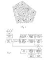
- Fig.1 shows the principle of an RTK network.
- the signals transmitted by a satellite 1 of a GNSS are received by receivers of a rover 2 in the field which position has to be determined with high precision and in parallel by reference stations 3 forming a network.
- the transmission of corrections from an RTK-network to a rover 2 is shown in Fig.2 .
- the signals transmitted by the satellites 1 of a GNSS are received by the receivers of the plurality of network reference stations 3. After a first processing in the reference stations 3 the signals are communicated to a network processing centre 4 where the corrections are calculated and subsequently transmitted via a transmitter 5 to the rover 2.
- the inventive method allows calculating of estimated accuracy for the dispersive or ionospheric component of the network RTK corrections and for potential or actual positions of the rover 2. Those values for estimated accuracy can be recorded and/or communicated to individual rovers in the field.
- Fig.3 shows a contour map of estimated accuracy for the dispersive or ionospheric component of the network RTK corrections according to prior art.
- the locations of the reference stations are shown as filled triangles. The boundary problems where the radial station-dependant estimates meet are apparent.
- Fig.4 shows a flow diagram illustrating the process for calculating the accuracy estimates which can then be used to generate maps according to the inventive method.
- Fig.5 a contour map of estimated accuracy for the dispersive or ionospheric component of the network RTK corrections calculated by the inventive method is shown.
- the locations of the reference stations are shown as filled triangles.
- Fig.6 shows a corresponding contour map of estimated accuracy for the non-dispersive or tropospheric and geometric component of the network RTK corrections.
- the locations of the reference stations are shown as filled triangles.
Abstract
In a method for accuracy estimation of network based corrections for a satellite-aided positioning system, with a network of reference stations code and phase measurements are recorded by the reference stations and transferred to a network processing centre. The measurements are converted to observables and single-differences between a master station and at least one auxiliary station selected for each reference station are calculated. Estimates of single-difference between each reference station and the corresponding master station are generated and slant residuals for each reference station and satellite are calculated by using the difference between calculated single-differences and estimates. Subsequently double-differences are formed by differencing between the slant residuals for each satellite s and the slant residuals of a reference satellite k, leading to zenith residuals calculated by mapping the double-differences to a zenith value. Error values for each reference station are computed by using the zenith residuals and error values for a potential rover position are estimated by combining error values of all reference stations.
The accuracy of network based corrections is represented graphically by generating a map as a grid of potential rover positions with estimated error values.
Description
- The invention relates to a method for accuracy estimation of network based corrections for a satellite-aided positioning system according to the pre-characterizing clause of
Claim 1, a method for graphically representing the accuracy of network based corrections, a method for recording and/or communicating accuracy estimates of network based corrections for individual rovers and a computer program product. - For satellite-aided positioning systems or global navigation satellite systems (GNSS), particularly the Global Positioning System (GPS), the multiple reference station RTK approach is widely known as a differential method for combining the data from a regional reference station network to provide precise measurement correction to users in the field. This is performed by measuring the regional errors at the reference station locations and interpolating them for the location of the rover. The quality of those corrections is dependent on the reference station spacing, the location of the rover, and the characteristics of the measurement errors.
- Generally, the quality of Network RTK corrections is a function of the following factors: network geometry, measurement errors, elimination of nuisance parameters (i.e. ambiguities), and the interpolation model that is used. All of these aspects are intermixed, for example, the interpolation model that is used should have the same spatial shape as the measurement errors. Alternatively, if the measurement errors are uniform then the reference stations can be located further away than if the measurement errors are not uniform.
- The factors that affect Network RTK performance are generally focused around the qualities and characteristics of the measurement errors. An accurate understanding of the measurement errors leads to an optimal interpolation model and network geometry for a given level of desired rover performance.
- In some of the more advanced cases of prior art the measurement error properties are extrapolated using network geometry to predict the performance for the rover in addition to the performance of the network. Many quality indicators for network RTK use the residual errors measured by the network reference stations to derive the current error conditions and characteristics. These characteristics are compared against the current interpolation model to determine the model residuals. For example, if the measured network residuals are linear and a linear interpolation model is used then there is a high likelihood that the rover will experience a high level of performance. The model residuals can then be used to predict the model inaccuracies as a function of the distance to the nearby reference stations. For example, if the model residuals are high but the rover is at a reference station then the model errors have no effect.
- The ability to determine the model residuals is a function of the degrees of freedom of the interpolation model. If there are no degrees of freedom then no residuals can be determined. In this case degrees of freedom can be created by excluding one of the reference stations from the model calculation.
- Network-Based RTK methods use a network of reference stations to measure the correlated error over a region and to predict their effects spatially and temporally within the network. Although the name suggests that these methods are real-time specific, they can also be used in postmission analysis. This process can reduce the effects of the correlated errors much better than the single reference station approach, thus allowing for reference stations to be spaced much further apart thereby covering a larger service area than the traditional approach, while still maintaining the same level of rover performance.
- Network RTK is comprised of six main processes:
- 1. Processing of the reference station data to resolve the network ambiguities,
- 2. Selection of the reference stations that will contribute to the corrections for the rover,
- 3. Generation of the network corrections,
- 4. Interpolation of the corrections for the rover's location,
- 5. Formatting and transmission of the corrections and
- 6. Computation of the rover position.
- The main task of the network computation is to resolve the ambiguities for all stations in the network to a common ambiguity level, such that the bias caused by the ambiguities is cancelled when double differences are formed. The network correction computation uses the ambiguity levelled phase observations from the network reference stations to precisely estimate the differential correlated errors for the region.
- A subset of stations from the reference network, known as a cell, is selected to generate the correction for the rover based on the rover's position. One station in the cell, usually the one closest to the rover, is selected as the master station. The correction interpolation process models the network corrections to determine the effects of the correlated errors at the rover's position. Depending on the correction concept (master-auxiliary, VRS or FKP), the interpolation may be done either by the reference station software or the rover itself. The corrections are formatted in such a way that the rover or standard RTK software can interpret them.
- In
US 5,323,322 a networked differential GPS system is disclosed that provides interpolations of reference station corrections tailored for particular user locations between the reference stations. Each reference station takes real-time ionospheric measurements with codeless cross-correlating dual-frequency carrier GPS receivers and computes real-time orbit ephemeredes independently. An absolute pseudo-range correction (PRC) is defined for each satellite as a function of a particular user's location. A map of the function is constructed, with "iso-PRC" contours, wherein the network measures the PRCs at a few points, so-called reference stations and constructs an iso-PRC map for each satellite. Corrections are interpolated for each user's site on a subscription basis. Although a central processing facility comprising means for generating quality control information by using over-specified reference station information and applying a root-sum-squares algorithm is disclosed, no further specification of the quality control information is given and no map like representation is specified. - In Wanninger, L. (2004): "Ionospheric Disturbance Indices for RTK and Network RTK Positioning", Proc. of ION GNSS 2004, Long Beach, CA an approach with an ionospheric Network RTK index I95L is disclosed where the index is computed from a 4 station sub-network with the ionospheric correction model being based on the observations of 3 surrounding reference stations and a fourth station being used as a monitor station. However, the approach provides only an index without calculation of values for a given rover location. Further, the index does not apply to the non-dispersive, i.e. troposphere and geometry component.
- Wübbena, G., Schmitz, M., Bagge, A. (2004) "GNSMART Irregularity Readings for Distance Dependent Errors ", White Paper, Geo++, mention the ionospheric delay of GNSS observations as the major error source in the atmosphere, which results into a dependency of a GNSS user from the separation to a reference station. Therefore, focus is placed on the ionospheric error component with an irregularity proposed as an indicator to decide on processing strategies on a RTK rover system in the field. However, the approach is based on per satellite residuals and does not calculate values for a given rover location. The distance based irregularity parameter is discontinuous and applies only to the dispersive component.
- Two different ionospheric linearity indicators to predict Network RTK performance are proposed in Chen, X., Landau, H., Vollath, U., (2003) "New Tools for Networked RTK Integrity Monitoring", ION GPS/GNSS 2003, Sept. 9-12, 2003, Portland, Oregon. The ionospheric residual integrity monitoring omits one reference station from interpolation and then compares the interpolation results at that station with the real measurements. It computes a weighted RMS over all satellites which can also be considered as integrity monitoring for residual interpolation and ambiguity resolution in the network. The ionospheric residual interpolation uncertainty as second indicator uses sufficient surrounding reference stations and produces standard deviation of interpolation with an interpolation method such as weighted linear interpolation method. The standard deviation represents the ionospheric linearity over the interpolation region for the field user. In this document it is also proposed to use similar indicators that can be used for the non-dispersive part. However, neither non-dispersive errors are disclosed in detail nor are equations specified. The values are generated when a position (latitude, longitude and height) is received from a rover. This requires the rover to determine the height and to transmit the information. Further, the model is discontinuous, i.e. artificial irregularities do exist between different parts of the network, and does not use the data of the whole network in the calculation of the quality estimates. The representation is based on the distance and change in height from a single reference station.
- An overview of prior art is also given in Alves, P., Geisler, I., Brown, N., Wirth, J. and Euler, H.-J. (2005) "Network RTK Quality Indication Using Linear Interpolation Residuals", GNSS 2005, Dec. 8-10, 2005, Hong Kong. In this document also a network RTK quality indicator based on the characteristics of the measurement errors is introduced. The indicator assumes that the more linear the regional correlated errors, the better the interpolation methods will perform. The linearity of the network measurement errors is measured and weighted based on the distance to the rover. However, the approach also is discontinuous and does not use the data of the whole network in the calculations. It does not apply to the non-dispersive component and does not use height information.
- An object of the invention is to provide an improved method for calculating and representing, e.g. graphically, correction-related values, such as error estimates, for a GNSS.
- A further object is to provide a method which permits improved calculation of solutions of base lines coordinated with one another.
- Another object is to provide a continuous representation of network RTK accuracy, particularly a graphical representation.
- A further object is to provide a method which allows calculating, recording and communicating correction-related values for the location of a real rover or for arbitrary points in the vicinity of reference stations.
- A further object is to provide an improved method which incorporates ionospheric and non-ionospheric errors.
- These objects are achieved, according to the invention, by the features of
Claim 1 and by the features of the sub claims or the solutions are further developed. - The present invention relates to a method for continuous representation of network RTK accuracy for a satellite-aided positioning system. The inventive approach is based on a continuous interpolation technique that is used to avoid introduction of boundary discrepancies and irregularities which occur when switching between reference stations or sets of reference stations. In order to achieve this result data from all reference stations within the network - as opposed to a subset of reference stations near the rover - are used in the calculation of the RMS values at each rover location. A specific embodiment combines information from a digital elevation model so that realistic values for the non-dispersive component can be computed over a defined region and without transmission of height information by the rover. Thereby, the system does not require position data or other input from the rover.
- Based on this approach the inventive method gives an easy to interpret representation of the accuracy of the network RTK corrects over the entire area of the network and provides information on where the highest errors are in the network, enabling the operator to decide where to put new reference stations. Also, the method shows the impact of station outages on the performance of the system.
- The calculation of error values is performed by carrying out the following steps
- 1. Raw code and phase measurements are recorded by multiple receivers tracking signals from GNSS satellites on two or more frequencies. The measurements are transferred, either in real time or offline, to a network processing centre. In the case of phase measurements, the processing centre adjusts the measurements to a common ambiguity level, e.g. as disclosed in RTCM (2007) "RTCM Standard 10403.1 Differential GNSS (Global Navigation Satellite Systems) Services - . This information can be obtained via the standardized RTCM v3.1 Network RTK Messages or via proprietary data formats directly from the network processing software.
- 2. For each receiver in the network and for each tracked satellite the measurements on the different GNSS frequencies (e.g. L1, L2, L5, E1, E5, E6) are converted to non-dispersive (troposphere and geometry) and dispersive (ionosphere) observables, refer to RTCM (2007) "RTCM Standard 10403.1 Differential GNSS (Global Navigation Satellite Systems) Services - .
- 3. For each reference station in the network, a set of nearby reference stations is chosen. One of the nearby reference stations is selected as a master station. Baselines are formed between the master station and the other nearby reference stations (auxiliary stations) using between-receiver single differences, see also Leick, Alfred (1995) : "GPS Satellite Surveying", 2nd Edition. A Wiley-Interscience Publication, John Wiley & Sons, New York, page 259. Single difference values are computed for both the dispersive and non-dispersive observables.
- 4. Estimates of the single difference dispersive and non-dispersive error between each reference station and its designated master station are made. The estimates can be obtained by interpolating the single difference values between the master and auxiliary stations. Correction smoothing may be applied to reduce the influence of measurement noise and multipath. Suitable methods of interpolation include the linear combination model, distance-based linear interpolation method, linear interpolation method, low-order surface model and least squares collocation as disclosed in Dai et Dai, L., Han, S., Wang, J., & Rizos, C. (2004) "Comparison of interpolation techniques in network-based GPS techniques", Navigation, 50(4), 277-293, page 278).
- 5. Slant residuals are calculated for each reference station and satellite using the difference between the measured and estimated single differences


where ν is the slant residual, Δ is the single difference operator, Φ is a measured code or ambiguity leveled phase range and Φ̂ is an estimated code or ambiguity leveled phase range. - 6. In order to eliminate the single difference ambiguity bias, double differences are formed by differencing between the slant residuals for each satellite s and the slant residuals of a reference satellite k


where Δ∇ is the double difference operator. - 7. The double difference slant residuals are mapped to a zenith value using a suitable mapping function, e.g. zdispersive =∇Δν dispersive .sin(θ) and znon-dispersive=∇Δνnon-dispersive .sin(θ) where θ is the satellite elevation in radians.
- 8. RMS values Ir and Tr are computed for each reference station r for the dispersive and non-dispersive errors respectively using the double difference zenith residuals


where m is the number of double-difference zenith residuals zdispersive and znon-dispersive. - 9. For the dispersive error, the RMS at each of the reference stations is used to estimate the RMS at a particular rover location (latitude and longitude) which may be inside or outside the boundaries of the network. A continuous interpolation technique is used to avoid introduction of boundary discrepancies and irregularities which occur when switching between reference stations or sets of reference stations.
The dispersive RMS I φ,λ at a defined latitude and longitude φ,λ can be estimated using
where Ir is the dispersive RMS at reference station r, n is the number of reference stations in the network,
- 10. For the non-dispersive error, the RMS at each reference station is used together with a digital elevation model to estimate the RMS at a particular rover location (latitude, longitude and height) which may be inside or outside the boundaries of the network. A continuous interpolation technique is used to avoid introduction of boundary discrepancies and irregularities which occur when switching between reference stations or sets of reference stations.
The non-dispersive RMS Tφ,λ,h at a defined latitude, longitude and height φ,λ,h can be estimated using
where Tr is the non-dispersive RMS at reference station r, n is the number of reference stations in the network,
- 11. The estimated RMS values are used to provide validity and usability information to the rover user and the network operator. This estimated RMS values can be used to generate maps by estimating values for a grid which can be then used to set the value of a pixel in computer graphics or as the basis for generation of a contour map.
- In a specific embodiment for estimation of the residual error for a single base RTK user - as opposed to a network RTK user -
step 3 is modified and replaced with the following alternative whereasstep 4 is not needed for this task - 3. For each reference station in the network, select the nearest reference station a master station. Form a baseline between each reference station and its master using between-receiver single differences as disclosed in Leick, Alfred (1995): "GPS Satellite Surveying" 2nd Edition. A Wiley-Interscience Publication, John Wiley & Sons, New York, page 259. Single difference values are computed for both the dispersive and non-dispersive observables.
- 4. This step is not needed for single base RTK residual estimation.
- The method according to the invention is shown schematically below by means of drawings and described in more detail purely by way of example. Specifically,
- Fig.1
- shows the principle of an RTK network;
- Fig.2
- shows the transmission of corrections from an RTK-network to a rover;
- Fig.3
- shows a contour map of estimated accuracy for the dispersive (ionospheric) component of the network RTK corrections according to prior art;
- Fig.4
- shows a flow diagram illustrating the process for calculating the accuracy estimates which can then be used to generate maps;
- Fig.5
- shows a contour map of estimated accuracy for the dispersive (ionospheric) component of the network RTK corrections and
- Fig.6
- shows a contour map of estimated accuracy for the non-dispersive (tropospheric and geometric) component of the network RTK corrections.
-
Fig.1 shows the principle of an RTK network. The signals transmitted by asatellite 1 of a GNSS are received by receivers of arover 2 in the field which position has to be determined with high precision and in parallel byreference stations 3 forming a network. - The transmission of corrections from an RTK-network to a
rover 2 is shown inFig.2 . The signals transmitted by thesatellites 1 of a GNSS are received by the receivers of the plurality ofnetwork reference stations 3. After a first processing in thereference stations 3 the signals are communicated to anetwork processing centre 4 where the corrections are calculated and subsequently transmitted via atransmitter 5 to therover 2. The inventive method allows calculating of estimated accuracy for the dispersive or ionospheric component of the network RTK corrections and for potential or actual positions of therover 2. Those values for estimated accuracy can be recorded and/or communicated to individual rovers in the field. -
Fig.3 shows a contour map of estimated accuracy for the dispersive or ionospheric component of the network RTK corrections according to prior art. The locations of the reference stations are shown as filled triangles. The boundary problems where the radial station-dependant estimates meet are apparent. -
Fig.4 shows a flow diagram illustrating the process for calculating the accuracy estimates which can then be used to generate maps according to the inventive method. - In
Fig.5 a contour map of estimated accuracy for the dispersive or ionospheric component of the network RTK corrections calculated by the inventive method is shown. The locations of the reference stations are shown as filled triangles. -
Fig.6 shows a corresponding contour map of estimated accuracy for the non-dispersive or tropospheric and geometric component of the network RTK corrections. The locations of the reference stations are shown as filled triangles. - The embodiments shown represent only examples of possible reference station networks and GNSS and are therefore not to be understood as being definitive and limiting. Moreover, the person skilled in the art can derive further frequencies and algorithms suitable for a method according to the invention, for example for GALILEO or GLONASS.
Claims (13)
- A method for accuracy estimation with continuous representation of network based corrections for a satellite-aided positioning system, with a network of reference stations (3) for receiving signals transmitted by satellites (1) of the positioning system and transmitting corrections to a rover (2), particularly an RTK network, comprising the steps• recording code and phase measurements by the reference stations (3),• transferring the measurements to a network processing centre (4),• converting the measurements to dispersive and/or non-dispersive observables,• calculating single-differences between a master station and at least one auxiliary station selected for each reference station (3),• generating estimates of single-difference between each reference station (3) and the corresponding master station, particularly by interpolating single difference values between the master station and the corresponding auxiliary stations,• calculating slant residuals for each reference station (3) and satellite (1) by using the difference between calculated single-differences and estimates,• forming double-differences by differencing between the slant residuals for each satellite s and the slant residuals of a reference satellite k,• calculating zenith residuals by mapping the double-differences to a zenith value,• computing dispersive and/or non-dispersive error values for each reference station by using the zenith residuals,characterized by• estimating the dispersive and/or non-dispersive error values for a potential or actual rover position by combining dispersive and/or non-dispersive error values of all reference stations (3).
- The method according to claim 1,
characterized in that
the single-differences are calculated for each reference station (3) between a master station and a set of nearby reference stations as auxiliary stations. - The method according to claim 1 or 2,
characterized in that
interpolating uses a linear combination model, distance-based linear interpolation method, linear interpolation method, low-order surface model or least squares collocation. - The method according to anyone of the preceding claims,
characterized in that
the non-dispersive error values for a potential or actual rover position are estimated by using a digital elevation model which provides the height information for the potential rover position. - The method according to anyone of the preceding claims,
characterized in that
the slant residuals are calculated according to

where ν is the slant residual, Δ is a single difference operator, Φ is a measured code or ambiguity leveled phase range and Φ̂ is an estimated code or ambiguity leveled phase range. - The method according to claim 5,
characterized in that
the double-differences are formed according to

where ∇Δ is the double difference operator. - The method according to claim 6,
characterized in that
the zenith residuals zdispersive and/or znon-dispersive are calculated with the mapping function Zdispersive=∇Δνdispersive.sin(θ) and znon-dispersive=∇Δnon-dispersive .sin(θ) where θ is the satellite elevation in radians. - The method according to claim 7,
characterized in that
the dispersive error values Ir and/or non-dispersive error values Tr are computed for each reference station r using the double difference zenith residuals

where m is the number of zenith residuals zdispersive and znon-dispersive. - The method according to claim 8,
characterized in that
the dispersive error value Iφ,λ for a potential or actual rover position at a defined latitude and longitude φ,λ is estimated as
where Ir is the dispersive error value at reference station r, n is the number of reference stations (3) in the network,
- The method according to claim 8 or 9,
characterized in that
the non-dispersive error value T φ,λ,h for a potential or actual rover position at a defined latitude, longitude and height φ,λ,h is estimated as
where Tr is the non-dispersive error value at reference station r, n is the number of reference stations in the network,
- Method for graphically representing the accuracy of network based corrections with generating a map by estimating error values for a grid of potential rover positions with the method according to the method of anyone of claims 1 to 10.
- Method for recording and/or communicating accuracy estimates of network based corrections for individual rovers by estimating error values for the rover's positions with the method according to the method of anyone of claims 1 to 10.
- Computer program product as a recording on a data medium or in the form of a data signal with code sequences for carrying out the method according to anyone of Claims 1 to 12.
Priority Applications (7)
| Application Number | Priority Date | Filing Date | Title |
|---|---|---|---|
| EP07116661A EP2040090A1 (en) | 2007-09-18 | 2007-09-18 | Method for accuracy estimation of network based corrections for a satellite-aided positioning system |
| CA2699388A CA2699388C (en) | 2007-09-18 | 2008-08-22 | Method for accuracy estimation of network based corrections for a satellite-aided positioning system |
| CN2008801075614A CN101802643B (en) | 2007-09-18 | 2008-08-22 | Method for accuracy estimation of network based corrections for a satellite-aided positioning system |
| PCT/EP2008/006905 WO2009036860A1 (en) | 2007-09-18 | 2008-08-22 | Method for accuracy estimation of network based corrections for a satellite-aided positioning system |
| AU2008300961A AU2008300961B2 (en) | 2007-09-18 | 2008-08-22 | Method for accuracy estimation of network based corrections for a satellite-aided positioning system |
| US12/678,720 US8072373B2 (en) | 2007-09-18 | 2008-08-22 | Method for accuracy estimation of network based corrections for a satellite-aided positioning system |
| EP08785668A EP2191290B1 (en) | 2007-09-18 | 2008-08-22 | Method for accuracy estimation of network based corrections for a satellite-aided positioning system |
Applications Claiming Priority (1)
| Application Number | Priority Date | Filing Date | Title |
|---|---|---|---|
| EP07116661A EP2040090A1 (en) | 2007-09-18 | 2007-09-18 | Method for accuracy estimation of network based corrections for a satellite-aided positioning system |
Publications (1)
| Publication Number | Publication Date |
|---|---|
| EP2040090A1 true EP2040090A1 (en) | 2009-03-25 |
Family
ID=38984102
Family Applications (2)
| Application Number | Title | Priority Date | Filing Date |
|---|---|---|---|
| EP07116661A Withdrawn EP2040090A1 (en) | 2007-09-18 | 2007-09-18 | Method for accuracy estimation of network based corrections for a satellite-aided positioning system |
| EP08785668A Active EP2191290B1 (en) | 2007-09-18 | 2008-08-22 | Method for accuracy estimation of network based corrections for a satellite-aided positioning system |
Family Applications After (1)
| Application Number | Title | Priority Date | Filing Date |
|---|---|---|---|
| EP08785668A Active EP2191290B1 (en) | 2007-09-18 | 2008-08-22 | Method for accuracy estimation of network based corrections for a satellite-aided positioning system |
Country Status (6)
| Country | Link |
|---|---|
| US (1) | US8072373B2 (en) |
| EP (2) | EP2040090A1 (en) |
| CN (1) | CN101802643B (en) |
| AU (1) | AU2008300961B2 (en) |
| CA (1) | CA2699388C (en) |
| WO (1) | WO2009036860A1 (en) |
Cited By (2)
| Publication number | Priority date | Publication date | Assignee | Title |
|---|---|---|---|---|
| CN104035112A (en) * | 2014-05-28 | 2014-09-10 | 中国科学院光电研究院 | Method for utilizing virtual elevation model to assist satellite navigation positioning in urban environment |
| CN110501733A (en) * | 2019-07-26 | 2019-11-26 | 武汉攀达时空科技有限公司 | A kind of adaptive grid VRS is generated and method of servicing |
Families Citing this family (21)
| Publication number | Priority date | Publication date | Assignee | Title |
|---|---|---|---|---|
| FR2943138B1 (en) * | 2009-03-13 | 2013-03-08 | Centre Nat Etd Spatiales | GEOPOSITIONING METHOD USING ASSISTANCE DATA |
| US9116228B2 (en) | 2012-08-09 | 2015-08-25 | Novatel Inc. | Low latency centralized RTK system |
| EP3163324B1 (en) * | 2014-06-25 | 2022-01-05 | Mitsubishi Electric Corporation | Positioning device, positioning method, and program |
| CN104102822B (en) * | 2014-07-01 | 2017-06-13 | 同济大学 | A kind of multifrequency GNSS observations stochastic behaviour modeling method |
| US10021668B2 (en) * | 2015-02-24 | 2018-07-10 | Mitsubishi Electric Corporation | Wireless characteristic display apparatus, wireless characteristic display method, and computer readable medium |
| US10379225B2 (en) * | 2016-03-18 | 2019-08-13 | Deere & Company | Satellite navigation receiver with improved ambiguity resolution |
| CN106407560B (en) * | 2016-09-19 | 2019-03-19 | 武汉大学 | Characterize the construction method of the anisotropic troposphere mapping function model of atmosphere |
| CN108205150B (en) * | 2016-12-19 | 2021-07-27 | 千寻位置网络有限公司 | Differential positioning method and system |
| CN106814381B (en) * | 2017-01-19 | 2019-07-05 | 湖南北云科技有限公司 | A kind of instant reference station positioning authentication method and system |
| DE102017103894B3 (en) * | 2017-02-24 | 2018-06-28 | Geo++ GmbH | Method for calibrating a GNSS antenna of a vehicle |
| CN108828626B (en) * | 2018-07-02 | 2020-11-06 | 中国人民解放军战略支援部队信息工程大学 | Network RTK ionosphere delay interpolation method and system based on real-time grid |
| CN108981559B (en) * | 2018-08-28 | 2020-05-01 | 郑州信大先进技术研究院 | Real-time deformation monitoring method and system based on Beidou foundation enhancement system |
| CN109490932B (en) * | 2018-12-26 | 2022-08-23 | 上海司南卫星导航技术股份有限公司 | Method for judging reliability of RTK (real time kinematic) orientation result, OEM (original equipment manufacturer) board card, receiver and storage medium |
| EP3730970B1 (en) * | 2019-04-23 | 2023-10-04 | Leica Geosystems AG | Providing atmospheric correction data for a gnss network-rtk system by encoding the data according to a quad-tree hierarchy |
| US11656081B2 (en) * | 2019-10-18 | 2023-05-23 | Anello Photonics, Inc. | Integrated photonics optical gyroscopes optimized for autonomous terrestrial and aerial vehicles |
| CN113359162A (en) * | 2021-04-07 | 2021-09-07 | 武汉大学 | Tropospheric delay and multipath error separation method and system based on large altitude difference |
| CN113552599B (en) * | 2021-07-07 | 2023-11-21 | 杭州中科微电子有限公司 | GNSS receiver antenna phase center correction method and device based on information fusion |
| CN114397680A (en) * | 2022-01-17 | 2022-04-26 | 腾讯科技(深圳)有限公司 | Error model determination method, device, equipment and computer readable storage medium |
| CN115061170B (en) * | 2022-07-13 | 2023-12-01 | 武汉大学 | Short-distance large-height difference environment network RTK method |
| CN117202342B (en) * | 2023-08-04 | 2024-03-08 | 北京讯腾智慧科技股份有限公司 | Regional reference station network RTK positioning service evaluation method and device based on PPK |
| CN116931007B (en) * | 2023-08-31 | 2023-12-08 | 腾讯科技(深圳)有限公司 | Ionosphere delay processing method, ionosphere delay processing device, ionosphere delay processing equipment and storage medium |
Citations (1)
| Publication number | Priority date | Publication date | Assignee | Title |
|---|---|---|---|---|
| US5323322A (en) * | 1992-03-05 | 1994-06-21 | Trimble Navigation Limited | Networked differential GPS system |
Family Cites Families (4)
| Publication number | Priority date | Publication date | Assignee | Title |
|---|---|---|---|---|
| US5477458A (en) * | 1994-01-03 | 1995-12-19 | Trimble Navigation Limited | Network for carrier phase differential GPS corrections |
| KR101100531B1 (en) * | 2003-04-17 | 2011-12-30 | 세크러터리 오브 스테이트 포 디펜스 | Correction of troposphere induced errors in global positioning systems |
| US7248211B2 (en) * | 2004-07-26 | 2007-07-24 | Navcom Technology Inc. | Moving reference receiver for RTK navigation |
| DE112007000563T5 (en) * | 2006-03-07 | 2009-01-08 | Trimble Navigation Ltd., Sunnyvale | GNSS signal processing method and apparatus |
-
2007
- 2007-09-18 EP EP07116661A patent/EP2040090A1/en not_active Withdrawn
-
2008
- 2008-08-22 CN CN2008801075614A patent/CN101802643B/en active Active
- 2008-08-22 WO PCT/EP2008/006905 patent/WO2009036860A1/en active Application Filing
- 2008-08-22 CA CA2699388A patent/CA2699388C/en not_active Expired - Fee Related
- 2008-08-22 EP EP08785668A patent/EP2191290B1/en active Active
- 2008-08-22 AU AU2008300961A patent/AU2008300961B2/en not_active Ceased
- 2008-08-22 US US12/678,720 patent/US8072373B2/en active Active
Patent Citations (1)
| Publication number | Priority date | Publication date | Assignee | Title |
|---|---|---|---|---|
| US5323322A (en) * | 1992-03-05 | 1994-06-21 | Trimble Navigation Limited | Networked differential GPS system |
Non-Patent Citations (6)
| Title |
|---|
| CHEN X ET AL: "New Tools for Network RTK Integrity Monitoring", PROCEEDINGS OF ION GPS/GNSS, XX, XX, 9 September 2003 (2003-09-09), pages 1355 - 1360, XP002400969 * |
| G. WÜBBENA ET AL.: "GNSMART Irregularity Readings for Distance Dependent Errors", GEO++ WHITE PAPER, 22 July 2004 (2004-07-22), Germany, pages 1 - 6, XP002469548 * |
| H.-J: EULER, B.E. ZEBHAUSER: "The Use of Standardized Network RTK Messages in Rover Applications for Surveying", PROCEEDINGS OF THE ION NTM 2003, 24 January 2003 (2003-01-24), USA, pages 377 - 384, XP002469545 * |
| L. DAI ET AL.: "Comparison of interpolation algorithms in network-based GPS techniques", NAVIGATION (JOURNAL OF THE INSTITUTE OF NAVIGATION, ION), vol. 50, no. 4, 2003, USA, pages 277 - 293, XP002469549 * |
| L. WANNINGER: "Ionospheric Disturbance Indices for RTK and Network RTK Positioning", PROCEEDINGS OF ION GNSS 2004, 24 September 2004 (2004-09-24), USA, pages 2849-2854, XP002469547 * |
| P.ALVES ET AL.: "Introduction of a Geometry", PROCEEDINGS OF ION GNSS 2005, 16 September 2005 (2005-09-16), USA, pages 2552 - 2563, XP002469546 * |
Cited By (3)
| Publication number | Priority date | Publication date | Assignee | Title |
|---|---|---|---|---|
| CN104035112A (en) * | 2014-05-28 | 2014-09-10 | 中国科学院光电研究院 | Method for utilizing virtual elevation model to assist satellite navigation positioning in urban environment |
| CN104035112B (en) * | 2014-05-28 | 2016-05-04 | 中国科学院光电研究院 | Utilize the method for satellite navigation location under the auxiliary urban environment of virtual elevation model |
| CN110501733A (en) * | 2019-07-26 | 2019-11-26 | 武汉攀达时空科技有限公司 | A kind of adaptive grid VRS is generated and method of servicing |
Also Published As
| Publication number | Publication date |
|---|---|
| WO2009036860A1 (en) | 2009-03-26 |
| US20100207817A1 (en) | 2010-08-19 |
| CA2699388A1 (en) | 2009-03-26 |
| EP2191290B1 (en) | 2012-12-19 |
| AU2008300961B2 (en) | 2011-02-03 |
| CN101802643B (en) | 2013-07-24 |
| EP2191290A1 (en) | 2010-06-02 |
| CA2699388C (en) | 2013-04-30 |
| AU2008300961A1 (en) | 2009-03-26 |
| US8072373B2 (en) | 2011-12-06 |
| CN101802643A (en) | 2010-08-11 |
Similar Documents
| Publication | Publication Date | Title |
|---|---|---|
| EP2191290B1 (en) | Method for accuracy estimation of network based corrections for a satellite-aided positioning system | |
| CN109581452B (en) | GNSS reference station carrier phase integer ambiguity resolution method | |
| EP3035080B1 (en) | Navigation satellite system positioning involving the generation of correction information | |
| EP2746811B1 (en) | Methods for generating accuracy information on an ionosphere model for satellite navigation applications | |
| CN110297259B (en) | Grid-based method and system for monitoring availability of positioning enhancement information of reference station network | |
| CN111694030A (en) | BDS local difference method and system based on grid virtual observation value | |
| JP2017173327A (en) | Positioning method and positioning device using satellite positioning system | |
| KR102180302B1 (en) | System and method for ionospheric correction using pseudorange and double-difference carrier phase measurement | |
| CN104680008A (en) | Multi-reference station-based network RTK (Real Time Kinematic) area atmospheric error modeling method | |
| WO2017070732A1 (en) | A method of analysing a signal transmitted between a global satellite navigation satellite system and a receiver | |
| CN111381264A (en) | Long baseline ambiguity fixing method and platform in network RTK | |
| Zhao et al. | A variant of raw observation approach for BDS/GNSS precise point positioning with fast integer ambiguity resolution | |
| CN114924295A (en) | Carrier phase smoothing pseudorange positioning method, device and storage medium | |
| CN114935770B (en) | Method and device for accelerating precision single-point positioning convergence speed by multiple calendars | |
| CN112146557A (en) | GNSS-based real-time bridge deformation monitoring system and method | |
| Chen et al. | Models and performance of SBAS and PPP of BDS | |
| Duan et al. | Performance of Galileo satellite products determined from multi-frequency measurements | |
| Brack et al. | Operational multi-GNSS global ionosphere maps at GFZ derived from uncombined code and phase observations | |
| CN113568020A (en) | Satellite navigation positioning error correction method and device considering hardware inter-frequency difference | |
| Erol | An automated height transformation using precise geoid models | |
| Krypiak-Gregorczyk et al. | A new ionosphere monitoring service over the ASG-EUPOS network stations | |
| Elsayed et al. | Vertical ionospheric delay estimation for single-receiver operation | |
| Mageed | Accuracy Evaluation between GPS Virtual Reference Station (VRS) and GPS Real Time Kinamatic (RTK) Techniques | |
| Pu et al. | Triple-frequency ambiguity resolution for GPS/Galileo/BDS between long-baseline network reference stations in different ionospheric regions | |
| Innac et al. | Multi-GNSS single frequency precise point positioning |
Legal Events
| Date | Code | Title | Description |
|---|---|---|---|
| PUAI | Public reference made under article 153(3) epc to a published international application that has entered the european phase |
Free format text: ORIGINAL CODE: 0009012 |
|
| AK | Designated contracting states |
Kind code of ref document: A1 Designated state(s): AT BE BG CH CY CZ DE DK EE ES FI FR GB GR HU IE IS IT LI LT LU LV MC MT NL PL PT RO SE SI SK TR |
|
| AX | Request for extension of the european patent |
Extension state: AL BA HR MK RS |
|
| AKX | Designation fees paid | ||
| REG | Reference to a national code |
Ref country code: DE Ref legal event code: 8566 |
|
| STAA | Information on the status of an ep patent application or granted ep patent |
Free format text: STATUS: THE APPLICATION IS DEEMED TO BE WITHDRAWN |
|
| 18D | Application deemed to be withdrawn |
Effective date: 20090820 |