EP2040227A2 - Method for inspecting coins - Google Patents
Method for inspecting coins Download PDFInfo
- Publication number
- EP2040227A2 EP2040227A2 EP08014737A EP08014737A EP2040227A2 EP 2040227 A2 EP2040227 A2 EP 2040227A2 EP 08014737 A EP08014737 A EP 08014737A EP 08014737 A EP08014737 A EP 08014737A EP 2040227 A2 EP2040227 A2 EP 2040227A2
- Authority
- EP
- European Patent Office
- Prior art keywords
- coil
- signal
- measuring
- transmitting
- track
- Prior art date
- Legal status (The legal status is an assumption and is not a legal conclusion. Google has not performed a legal analysis and makes no representation as to the accuracy of the status listed.)
- Granted
Links
- 238000000034 method Methods 0.000 title claims abstract description 26
- 230000000737 periodic effect Effects 0.000 claims abstract 2
- 238000005259 measurement Methods 0.000 claims description 27
- 230000005540 biological transmission Effects 0.000 claims description 26
- 238000010606 normalization Methods 0.000 claims description 11
- 229910000859 α-Fe Inorganic materials 0.000 claims description 9
- 238000013016 damping Methods 0.000 claims description 8
- 239000000523 sample Substances 0.000 claims description 4
- 239000011162 core material Substances 0.000 description 12
- 230000001939 inductive effect Effects 0.000 description 10
- 238000010586 diagram Methods 0.000 description 7
- 238000011156 evaluation Methods 0.000 description 5
- 238000013461 design Methods 0.000 description 3
- 239000000463 material Substances 0.000 description 3
- 238000005070 sampling Methods 0.000 description 3
- 230000004888 barrier function Effects 0.000 description 2
- 230000035515 penetration Effects 0.000 description 2
- 238000012545 processing Methods 0.000 description 2
- 238000012360 testing method Methods 0.000 description 2
- 101710179738 6,7-dimethyl-8-ribityllumazine synthase 1 Proteins 0.000 description 1
- 101710186608 Lipoyl synthase 1 Proteins 0.000 description 1
- 101710137584 Lipoyl synthase 1, chloroplastic Proteins 0.000 description 1
- 101710090391 Lipoyl synthase 1, mitochondrial Proteins 0.000 description 1
- 230000008859 change Effects 0.000 description 1
- 238000010276 construction Methods 0.000 description 1
- 230000001419 dependent effect Effects 0.000 description 1
- 230000001627 detrimental effect Effects 0.000 description 1
- 230000002500 effect on skin Effects 0.000 description 1
- 230000008030 elimination Effects 0.000 description 1
- 238000003379 elimination reaction Methods 0.000 description 1
- 230000004907 flux Effects 0.000 description 1
- 238000000691 measurement method Methods 0.000 description 1
- 230000003287 optical effect Effects 0.000 description 1
- 230000008569 process Effects 0.000 description 1
- 230000000284 resting effect Effects 0.000 description 1
- 230000000630 rising effect Effects 0.000 description 1
- 238000010998 test method Methods 0.000 description 1
Images


Classifications
-
- G—PHYSICS
- G07—CHECKING-DEVICES
- G07D—HANDLING OF COINS OR VALUABLE PAPERS, e.g. TESTING, SORTING BY DENOMINATIONS, COUNTING, DISPENSING, CHANGING OR DEPOSITING
- G07D5/00—Testing specially adapted to determine the identity or genuineness of coins, e.g. for segregating coins which are unacceptable or alien to a currency
- G07D5/08—Testing the magnetic or electric properties
Definitions
- the invention relates to a method for testing coins according to claim 1.
- the invention relates to a method of testing coins by the inductive measuring method.
- this method relies on directing a magnetic signal from a transmitting coil onto a coin running along a track and receiving a receiving coil receiving the resulting signal.
- a more or less pronounced attenuation of the transmission signal takes place.
- the receiving coil both on the same side as the transmitting coil ( DE 10 2004 013 286 B4 ) as well as on the opposite side ( DE 689 21 608 T2 ).
- Such a circuit arrangement is also suitable for an inductive measuring arrangement, are arranged in the transmitting and receiving coil on different sides of the coin path.
- one speaks of a transmissive measurement while the measurement is referred to only on one side of the coin path as a reflective measurement.
- a periodically recurring portion of the transmission signal in a Number of switching steps divided. From the values of the received signal of the receiving coil, envelopes are formed at the respective switching steps repeating the frequency of the transmission signal.
- An evaluation device forms from the number of concurrently generated envelopes at least one criterion for generating the acceptance or return signal. In this measurement method, it is assumed that attenuation curves which generate a coin during the passage of the measuring device are significantly frequency-dependent. At low frequencies, the penetration depth is much greater than at high frequencies.
- the penetration depth is close to zero.
- the known measuring method one makes use of the property of, for example, a square wave signal consisting of a plurality of harmonics. In the section of the rectangular signal near its rising edge, the signal shape of the receiving coil is essentially determined by the high frequency components.
- the invention has for its object to provide a method for checking coins, which allows a particularly good discrimination of different coin designs of counterfeit coins.
- the inventive method is based on a specific Meßspulenan instruct.
- a transmitting and a receiving coil is arranged on a ferrite core.
- the diameter of the receiving coil which is closer to the track than the transmitting coil, is smaller than that of the transmitting coil, for example in the ratio of 1 to 2.
- the diameter of the transmitting coil is smaller than the diameter of the smallest coin to be accepted.
- a secondary coil is arranged, whose signal is fed back as a negative feedback signal to the transmitting coil. This is to ensure that a constant transmission signal can be given to the transmission coil.
- This method is, as already explained above, from the DE 198 36 490 C2 known. This document is expressly incorporated by reference.
- the arrangement of transmitting and receiving coil can be provided, for example, in the manner as in the already mentioned DE 10 2004 013 286 B4 is described.
- a transmit signal containing harmonics is generated periodically. This is for example a rectangle or triangle signal.
- the amplitudes of the damping function are determined from the input signals of the respective receiver coil at at least three chronologically different measuring times.
- At least four measuring cycles are run through.
- a reflection measurement is carried out in each case with the transmitting and receiving coil.
- the transmission coils are controlled on each side, and the reception signals of the receiving coils are evaluated on each side.
- two transmission measurements are carried out, wherein the transmitting coil of the respective opposite receiving coil is evaluated with their signals.
- the peculiarity is that in one case the receiving coil is formed by a transmitting coil.
- the order of the reflection and transmission measurements can be chosen arbitrarily.
- the measured values from the four measuring cycles are related to each other and / or compared with predetermined reference values.
- the receiving coils (with the exception of the case in which a transmitting coil is used as the receiving coil) have clearly different diameters compared to the transmitting coils, it is possible, for example.
- the waveforms vary according to the differences in the electrical and magnetic properties of the ring and core materials.
- the method according to the invention is not only suitable for distinguishing counterfeit coins from genuine ones, but also for classifying the inserted coin values.
- the coins are moved into abutment against a wall of the track, and in the transmission measurement, the coil arrangement associated with the wall forms the receiving side.
- a normalization of the measured values of the four cycles is carried out before the evaluation of the measurement results.
- a normalization can take place, for example, by shifting a quiescent level of the received signals to a standard level (one-point standardization).
- the quiescent level is known to be the state where no coin is in the measuring arrangement.
- the standard level is an arbitrary level.
- Another standardization can be carried out by shifting a first measured value of the respective cycle to a zero point. After determining the facing measured values or measured value curves, a better evaluation can take place in that the standardized measured values or measured value functions are spread.
- a sensor arranged in front of the inductive measuring arrangement can initiate the starting signal for the inductive measurement.
- this and / or another sensor is also possible to determine the relative position of a coin to the inductive measuring device, for example, to be able to better measure edge regions of a coin.
- edge regions of a coin With pronounced extreme values of the damping curves, it can also be readily ascertained that when a coin is centered to the measuring device. This serves, for example, to test the core material of a bicoloured coin.
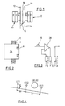
- FIG. 1 a coin channel 10 is shown with a first wall 12 and a second wall 14. An inclined bottom 16 of the coin channel 10 ensures that a coin 18 is guided along the wall 12.
- a first inductive measuring arrangement 20 and on the opposite side a second inductive measuring arrangement 22 is provided.
- the measuring arrangement 20 consists of a receiving coil A, a transmitting coil C and a secondary coil E.
- the measuring arrangement 22 has a receiving coil B, a transmitting coil D and a secondary coil F.
- the construction of the coil arrangement or measuring arrangement 20, 22 results from FIG. 2 ,
- the receiving coil A is seated with a significantly smaller diameter, for example, half the diameter of the transmitting coil C, in a recess of the ferrite core 24.
- the receiving coils A and B are located directly on the coin channel 10th
- a square-wave signal 26 reaches an input of a differential amplifier 28, which feeds the transmitting coil C.
- the transmitting coil C is inductively coupled to the secondary coil E and its output goes to a second input of the differential amplifier 28.
- the signal of the secondary coil E is given as a negative feedback signal to the differential amplifier 28 such that the signal of the secondary coil E coincides with the transmission signal.
- FIG. 5 is structurally the measuring arrangement according to FIG. 1 shown.
- the coin 18 is a bi-color coin with a rim 18a and a core 18b. It moves along the wall 12 of the main plate, in which the first coil arrangement 20 is arranged, wherein the transmitting coil A is located very close to the wall 12.
- the period of a measuring signal for example a square-wave signal, is for example 300 ⁇ s, where one pulse has a duration of 50 ⁇ s and the pause lasts 250 ⁇ s. Therefore, four cycles of 300 ⁇ s are required to complete four cycles.
- the measuring points of the measurements of the four cycles therefore have a distance of 1.2 milliseconds.
- a typical throughput time of a coin through the measuring arrangement of about 70 to 80 milliseconds, therefore, four measured values in the four cycles represent an immediate consequence and thus a measurement of material properties of the coin almost in the same place.
- the transmitting coil C is activated in the first cycle while the transmitting coil D is activated in the other three cycles.
- it is receiver coil A which generates the measurements
- receiver coil B generates the measurement signal
- in cycle 3 C is the receiver coil.
- the respective transmitting coil is subjected to the multi-frequency principle with a square wave, as in connection with EP 0 886 247 B1 already described. This document is expressly incorporated by reference.
- Each cycle can generate any number of measured values, for example 10, by means of a corresponding division of the transmitted pulse.
- the sensors LS1 to LS3 are, for example, optical light barriers, transmitters and receivers being arranged on the same side as the main plate of the coin validator, while a reflection element is arranged on the carrier plate, which reflects the light of the light transmitter onto the receiver.
- the light barrier or the sensor LS1 is the starting point for the measurement with the measuring device after the FIGS. 1 and 3 given. After starting the measurement, a quiescent level prevails until the damping starts.
- the minima are cup-shaped and thus very much flattened, so that it is relatively difficult to determine the time at which the coin is located centrally in the measuring arrangement.
- the minimum for the cycle TC is much more pronounced.
- the reason for this is that in this case a transmitting coil is used as a receiving coil. As mentioned several times, the transmitting coil has a significantly larger diameter than the receiving coils of the measuring arrangement.
- the distance of the sensor LS1 from the measuring arrangement is chosen so that the ring section of the 2 € Bicolor coin is positioned approximately centrally in front of the receiving coils.
- the arrow LS1 down indicates leaving the coin in front of the sensor LS 1.
- the property of the edge can be measured at the time at which the coin edge substantially affects the measuring arrangement.
- the edge of a bicolour coin has different material properties than the core.
- the core of the coin can be effectively determined by taking a measurement of that Time takes place in which the damping curve has its minimum. The minimum can be determined, for example, in the cycle TA.
- the sensor LS3 When leaving the coin of the sensor area, the sensor LS3 generates a signal which can end the measuring process.
- the speed of the coin can also be measured, e.g. to determine a minimum.
- a diameter measurement can take place, as it is known per se with the aid of such sensors.
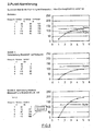
- FIG. 7 is an example of the evaluation of the measured values from the four cycles described reproduced.
- five measured values for the different switching steps 1 to 5 for the cycle RA are plotted. These are eg the minima of the curves RA1 to RA5 (not all drawn in).
- the course of such a curve corresponds to the deformation of a rectangular signal with which, for example, the transmitting coil C was fed.
- the diagram also contains the quiescent level R and a standard level.
- the quiescent level is shifted to the standard level, which leads to a raising of the curve (middle diagram).
- the distance between measured value 1 and quiescent level is set to approximately 100. This results in a spread of the curve, as shown in the bottom diagram.
- the influence of the air gap field is eliminated, which arises for example by the fact that the coin does not run smoothly along a track wall, but at a distance to this, the distance is also oscillating can change, depending on the movement of the coin on the track.
- FIG. 8 is another example of a standardization of measured values shown, a so-called two-point normalization.
- two-point normalization is meant that the distance of two specific measured values of the cycle RA is standardized, for example, from RA 1 to RA3.
- the measured values are plotted in a diagram with resting and standard levels (see top diagram).
- the first normalization step the measured value is pulled to the zero point.
- the distance between measured value 1 and measured value 2 is set to 100. In this way, there is an elimination of the influence of the air gap field and thus a disturbance on the determination of measurement results.
- the circuitry with which the individual cycles RA, RB, TC and TA are controlled is not shown. It is easily realizable.
- the electronic circuit for generating the transmission and processing of the received signals is also not shown. It is also understood that in addition to the cycles described also other measuring cycles can be performed in which, for example, the transmitting coil D receiving coil, while the coil C is activated as a transmitting coil.
Abstract
Description
Die Erfmdung bezieht sich auf ein Verfahren zum Prüfen von Münzen nach Patentanspruch 1.The invention relates to a method for testing coins according to
Die Erfindung bezieht sich insbesondere auf ein Verfahren zum Prüfen von Münzen nach dem induktiven Meßverfahren. Generell beruht dieses Verfahren darauf, daß von einer Sendespule ein magnetisches Signal auf eine entlang einer Laufbahn laufende Münze gerichtet wird und eine Empfangsspule das resultierende Signal empfängt. Abhängig von der Werkstoffzusammensetzung der Münze erfolgt eine mehr oder weniger ausgeprägte Dämpfung des Sendesignals. Es ist ferner allgemein bekannt, die Empfangsspule sowohl auf der gleichen Seite wie die Sendespule anzuordnen (
Für eine zuletzt beschriebene Anordnung ist aus
Die Erzeugung eines geeigneten Sendesignals, wie sie in
Mit steigender Zahl der Schaltschritte bestimmen überwiegend die niedrigeren Frequenzanteile die Signalform.As the number of switching steps increases, predominantly the lower frequency components determine the signal shape.
Aus der eingangs erwähnten
Der Erfindung liegt die Aufgabe zugrunde, ein Verfahren zum Prüfen von Münzen zu schaffen, das eine besonders gute Diskriminierung der verschiedensten Münzausführungen von Falschmünzen erlaubt.The invention has for its object to provide a method for checking coins, which allows a particularly good discrimination of different coin designs of counterfeit coins.
Diese Aufgabe wird durch die Merkmale des Patentanspruchs 1 gelöst.This object is solved by the features of
Das erfindungsgemäße Verfahren geht von einer bestimmten Meßspulenanordnung aus. Auf jeder Seite der Laufbahn ist auf einem Ferritkern eine Sende- und eine Empfangsspule angeordnet. Der Durchmesser der Empfangsspule, die näher zur Laufbahn liegt als die Sendespule, ist kleiner als der der Sendespule, beispielsweise im Verhältnis von 1 zu 2. Der Durchmesser der Sendespule ist kleiner als der Durchmesser der kleinsten anzunehmenden Münze. Auf dem Ferritkern ist, mit der Sendespule gekoppelt, eine Sekundärspule angeordnet, deren Signal als Gegenkopplungssignal auf die Sendespule rückgekoppelt ist. Damit soll erreicht werden, daß ein konstantes Sendesignal auf die Sendespule gegeben werden kann. Dieses Verfahren ist, wie weit oben bereits erläutert, aus der
Die Erzeugung von Sende- und Verarbeitung von Empfangssignalen ist ähnlich, wie in
Zeitlich nacheinander werden mindestens vier Meßzyklen durchlaufen. Auf jeder Seite der Laufbahn wird mit Sende- und Empfangsspule jeweils eine Reflektionsmessung durchgeführt. Hierbei werden die Sendespulen auf jeder Seite angesteuert, und es werden die Empfangssignale der Empfangsspulen auf jeder Seite ausgewertet. Außerdem werden zwei Transmissionsmessungen durchgeführt, wobei die der Sendespule jeweils gegenüberliegende Empfangsspule mit ihren Signalen ausgewertet wird. Die Besonderheit ist, daß in einem Fall die Empfangsspule von einer Sendespule gebildet ist. Die Reihenfolge der Reflexions- und Transmissionsmessungen kann beliebig gewählt werden. Die Meßwerte aus den vier Meßzyklen werden zueinander in Beziehung gesetzt und/oder mit vorgegebenen Referenzwerten verglichen.In chronological succession, at least four measuring cycles are run through. On each side of the track, a reflection measurement is carried out in each case with the transmitting and receiving coil. In this case, the transmission coils are controlled on each side, and the reception signals of the receiving coils are evaluated on each side. In addition, two transmission measurements are carried out, wherein the transmitting coil of the respective opposite receiving coil is evaluated with their signals. The peculiarity is that in one case the receiving coil is formed by a transmitting coil. The order of the reflection and transmission measurements can be chosen arbitrarily. The measured values from the four measuring cycles are related to each other and / or compared with predetermined reference values.
Da bei dem erfindungsgemäßen Verfahren die Empfangsspulen (mit Ausnahme des Falls, in dem eine Sendespule als Empfangsspule verwendet wird), deutlich unterschiedliche Durchmesser im Vergleich zu den Sendespulen haben, lassen sich z.B. bei der ringförmig angeordneten Bicolormünzen zeitgleich und unabhängig ermittelte Kurvenformen als Unterscheidungskriterium auswerten. Die Kurvenformen variieren entsprechend den Unterschieden der elektrischen und magnetischen Eigenschaften von Ring- und Kernmaterial.In the method according to the invention, since the receiving coils (with the exception of the case in which a transmitting coil is used as the receiving coil) have clearly different diameters compared to the transmitting coils, it is possible, for example. Evaluate at the same time and independently determined waveforms in the ring-shaped Bicolor coins as distinguishing criterion. The waveforms vary according to the differences in the electrical and magnetic properties of the ring and core materials.
Für den Fall, daß eine Sendespule als Empfangsspule verwendet wird, wird bei der maximalen Dämpfung im Vergleich zu den sonst verwendeten Empfangsspulen eine Kurvenform erhalten, die besser zur Bestimmung der zentrischen Position der Münze in der Spulenanordnung geeignet ist.In the event that a transmitting coil is used as a receiving coil, at the maximum attenuation compared to the otherwise used receiving coils, a waveform is obtained which is better suited for determining the centric position of the coin in the coil assembly.
Das erfindungsgemäße Verfahren ist nicht nur geeignet, Falschmünzen von echten zu unterscheiden, sondern auch die eingeworfenen Münzwerte zu klassifizieren.The method according to the invention is not only suitable for distinguishing counterfeit coins from genuine ones, but also for classifying the inserted coin values.
Nach einer vorzugsweisen Ausgestaltung der Erfindung werden die Münzen in Anlage an einer Wand der Laufbahn bewegt, und bei der Transmissionsmessung bildet die der Wand zugeordnete Spulenanordnung die Empfangsseite.According to a preferred embodiment of the invention, the coins are moved into abutment against a wall of the track, and in the transmission measurement, the coil arrangement associated with the wall forms the receiving side.
Nach einer weiteren Ausgestaltung der Erfmdung wird vor der Auswertung der Meßergebnisse eine Normierung der Meßwerte der vier Zyklen durchgeführt. Eine Normierung kann etwa dadurch erfolgen, daß ein Ruhepegel der Empfangssignale auf einen Normpegel verschoben wird (Einpunkt-Normung). Der Ruhepegel ist bekanntlich der Zustand, bei dem keine Münze sich in der Meßanordnung befindet. Der Normpegel ist ein willkürlich gewählter Pegel.According to a further embodiment of the invention, a normalization of the measured values of the four cycles is carried out before the evaluation of the measurement results. A normalization can take place, for example, by shifting a quiescent level of the received signals to a standard level (one-point standardization). The quiescent level is known to be the state where no coin is in the measuring arrangement. The standard level is an arbitrary level.
Eine andere Normung kann dadurch erfolgen, daß ein erster Meßwert des jeweiligen Zyklus auf einen Nullpunkt verschoben wird. Nach Bestimmung der zugekehrten Meßwerte bzw. Meßwertkurven kann eine bessere Auswertung dadurch erfolgen, daß die normierten Meßwerte bzw. Meßwertfunktionen gespreizt werden.Another standardization can be carried out by shifting a first measured value of the respective cycle to a zero point. After determining the facing measured values or measured value curves, a better evaluation can take place in that the standardized measured values or measured value functions are spread.
Es ist bekannt, etwa zur Durchmessermessung zwei weitere im Laufweg der Münzen versetzte Sonden vorzusehen, welche aus den Eintritts- und Austrittssignalen für eine Münze und deren Geschwindigkeit den Durchmesser der Münzen bestimmen. Erfindungsgemäß kann ein vor der induktiven Meßanordnung angeordneter Sensor das Startsignal für die induktive Messung initiieren. Mit Hilfe dieses und/oder eines weiteren Sensors ist auch möglich, die Relativposition einer Münze zur induktiven Meßanordnung zu bestimmen, um z.B. Randbereiche einer Münze besser vermessen zu können. Bei ausgeprägten Extremwerten der Dämpfungskurven läßt sich auch ohne weiteres feststellen, wann eine Münze sich mittig zur Meßanordnung befindet. Dies dient z.B. dazu, das Kernmaterial einer Bicolormünze zu testen.It is known, for example, to provide for the diameter measurement two further offset in the path of the coins probes, which determine from the entry and exit signals for a coin and their speed the diameter of the coins. According to the invention, a sensor arranged in front of the inductive measuring arrangement can initiate the starting signal for the inductive measurement. With the help of this and / or another sensor is also possible to determine the relative position of a coin to the inductive measuring device, for example, to be able to better measure edge regions of a coin. With pronounced extreme values of the damping curves, it can also be readily ascertained that when a coin is centered to the measuring device. This serves, for example, to test the core material of a bicoloured coin.
Die Erfindung wird nachfolgend anhand von Zeichnungen näher erläutert.
- Fig. 1
- zeigt schematisch eine Spulenanordnung zur Durchführung des erfindungsgemäßen Verfahrens.
- Fig. 2
- zeigt schematisch eine der beiden Spulenanordnungen nach
Fig. 1 . - Fig. 3
- zeigt die Schaltungsanordnung der Spulenanordnung nach
Fig. 2 . - Fig. 4
- zeigt die Anordnung einer induktiven Meßanordnung zur Durchführung des erfindungsgemäßen Verfahrens und drei weitere Meßsonden bzw. Sensoren.
- Fig. 5
- zeigt eine konstruktiv detailliertere induktive Meßanordnung nach
Fig. 1 . - Fig. 6
- zeigt jeweils drei Dämpfungskurven von drei Meßzyklen einer induktiven Meßanordnung nach
Fig. 1 bzw. 5. - Fig. 7
- zeigt verschiedene Tabellen und Kurven für eine Einpunkt-Normierung der Meßergebnisse.
- Fig. 8
- zeigt verschiedene Tabellen und Kurven für eine Zweipunkt-Normierung der Meßergebnisse des erfindungsgemäßen Verfahrens.
- Fig. 1
- schematically shows a coil assembly for carrying out the method according to the invention.
- Fig. 2
- schematically shows one of the two coil arrangements after
Fig. 1 , - Fig. 3
- shows the circuit arrangement of the coil assembly after
Fig. 2 , - Fig. 4
- shows the arrangement of an inductive measuring arrangement for carrying out the method according to the invention and three further measuring probes or sensors.
- Fig. 5
- shows a structurally more detailed inductive measuring device after
Fig. 1 , - Fig. 6
- shows in each case three attenuation curves of three measuring cycles of an inductive measuring arrangement
Fig. 1 or 5. - Fig. 7
- shows different tables and curves for a one-point normalization of the measurement results.
- Fig. 8
- shows various tables and curves for a two-point normalization of the measurement results of the method according to the invention.
In
Auf einem relativ langen Ferritkern 24, sind auf dessen Außenseite die Sendespule C und die Sekundärspule E angeordnet. Vorzugsweise sind die Spulen E und C bifilar gewickelt. Die Empfangsspule A sitzt mit einem deutlich kleineren Durchmesser, beispielsweise dem halben Durchmesser der Sendespule C, in einer Ausnehmung des Ferritkerns 24. Wie sich auch aus
Eine elektrische Verschaltung der Meßanordnung 20 geht aus
Die konstruktive Ausgestaltung der Anordnung nach
Mit der in
Nachstehend ein Beispiel für vier Zyklen mit der Meßanordnung nach
Wie aus der Tabelle hervorgeht, wird die Sendespule C im ersten Zyklus aktiviert, während die Sendespule D in den anderen drei Zyklen aktiviert wird. Bei den Zyklen 1 und 4 ist es die Empfängerspule A, welche die Meßwerte erzeugt, während beim Zyklus 2 die Empfängerspule B das Meßsignal erzeugt und im Zyklus 3 ist C die Empfangsspule.As shown in the table, the transmitting coil C is activated in the first cycle while the transmitting coil D is activated in the other three cycles. In
Die jeweilige Sendespule wird nach dem Multifrequenzprinzip mit einem Rechtecksignal beaufschlagt, wie es in Verbindung mit
Man erkennt, daß in den ersten beiden Zyklen 1 und 2 nach dem reflektiven und bei den Zyklen 3 und 4 nach dem Transmissionsprinzip gearbeitet wird.It can be seen that in the first two
Jeder Zyklus kann durch entsprechende Aufteilung des Sendeimpulses eine beliebige Anzahl von Meßwerten erzeugen, beispielsweise 10.Each cycle can generate any number of measured values, for example 10, by means of a corresponding division of the transmitted pulse.
Wobei der erste Meßwert nicht zum Zeitpunkt t = o des Sendeimpulses ermittelt wird, sondern erst nach einem vorgegebenen zeitlichen Offset damit ein stabiler Zustand der Verstärker gewährleistet ist.Wherein the first measured value is not determined at the time t = o of the transmission pulse, but only after a predetermined time offset so that a stable state of the amplifier is ensured.
Bei vorzugsweise 4 Zyklen werden somit 4 x 10 Meßwerte erzeugt, die zur Klassifizierung und Auswertung verwendet werden können.With preferably 4 cycles, 4 × 10 measured values are thus generated, which can be used for classification and evaluation.
Es reicht jedoch aus, nur zu bestimmten Abtastzeitpunkten Meßwerte zu wählen, beispielsweise bei den Abtastzeitpunkten 1,3 und 9 oder 1,2 und 9 oder dergleichen. Denn die unmittelbar benachbarten Abtastzeitpunkte ergeben zum Teil redundante Meßwerte, so daß die Anzahl der zu speichernden Referenzwerte auf diese Weise reduziert werden kann.However, it is sufficient to select measured values only at certain sampling times, for example at
In
Der Abstand des Sensors LS1 von der Meßanordnung ist so gewählt, daß der Ringabschnitt der 2 € Bicolormünze annähernd zentrisch vor den Empfangsspulen positioniert ist.The distance of the sensor LS1 from the measuring arrangement is chosen so that the ring section of the 2 € Bicolor coin is positioned approximately centrally in front of the receiving coils.
Der Pfeil LS1 nach unten zeigt das Verlassen der Münze vor dem Sensor LS 1 an.The arrow LS1 down indicates leaving the coin in front of the
Mithin kann die Eigenschaft des Randes zum Zeitpunkt gemessen werden, an dem der Münzrand wesentlich die Meßanordnung beeinflußt. Bekanntlich weist der Rand einer Bicolormünze andere Materialeigenschaften als der Kern auf. Der Kern der Münze kann wirksam bestimmt werden, indem eine Messung zu dem Zeitpunkt erfolgt, in dem die Dämpfungskurve ihr Minimum hat. Das Minimum läßt sich z.B. im Zyklus TA bestimmen.Consequently, the property of the edge can be measured at the time at which the coin edge substantially affects the measuring arrangement. As is known, the edge of a bicolour coin has different material properties than the core. The core of the coin can be effectively determined by taking a measurement of that Time takes place in which the damping curve has its minimum. The minimum can be determined, for example, in the cycle TA.
Der Sensor LS3 erzeugt beim Verlassen der Münze des Sensorbereichs ein Signal, das den Meßvorgang beenden kann. Mit Hilfe der gezeigten Sensoren kann auch die Geschwindigkeit der Münze gemessen werden, um z.B. ein Minimum zu bestimmen. Außerdem kann eine Durchmessermessung erfolgen, wie sie mit Hilfe derartiger Sensoren an sich bekannt ist.When leaving the coin of the sensor area, the sensor LS3 generates a signal which can end the measuring process. By means of the sensors shown, the speed of the coin can also be measured, e.g. to determine a minimum. In addition, a diameter measurement can take place, as it is known per se with the aid of such sensors.
In
Im ersten Normungsschritt wird der Ruhepegel auf den Normpegel verschoben, was zu einem Anheben der Kurve führt (mittleres Diagramm). Im zweiten Schritt wird der Abstand zwischen Meßwert 1 und Ruhepegel auf annähernd 100 gesetzt. Dabei ergibt sich eine Spreizung der Kurve, wie im untersten Diagramm dargestellt. Mit Einpunkt-Normierung nach
Mit Hilfe der Normierung wird der Einfluß des Luftspaltfeldes eliminiert, der etwa dadurch entsteht, daß die Münze nicht glatt an einer Laufbahnwand entlangläuft, sondern im Abstand zu dieser, wobei der Abstand sich auch oszillierend verändern kann, je nach Bewegung der Münze auf der Laufbahn.With the help of normalization, the influence of the air gap field is eliminated, which arises for example by the fact that the coin does not run smoothly along a track wall, but at a distance to this, the distance is also oscillating can change, depending on the movement of the coin on the track.
In
Die Schaltungsanordnung, mit der die einzelnen Zyklen RA, RB, TC und TA gesteuert werden, ist nicht gezeigt. Sie ist ohne weiteres realisierbar. Die elektronische Schaltung zur Erzeugung der Sende- und Verarbeitung der Empfangssignale ist ebenfalls nicht dargestellt. Es versteht sich außerdem, daß zusätzlich zu den beschriebenen Zyklen auch weitere Meßzyklen durchgeführt werden können, bei denen etwa die Sendespule D Empfangsspule ist, während die Spule C als Sendespule aktiviert wird.The circuitry with which the individual cycles RA, RB, TC and TA are controlled is not shown. It is easily realizable. The electronic circuit for generating the transmission and processing of the received signals is also not shown. It is also understood that in addition to the cycles described also other measuring cycles can be performed in which, for example, the transmitting coil D receiving coil, while the coil C is activated as a transmitting coil.
Claims (10)
Priority Applications (1)
| Application Number | Priority Date | Filing Date | Title |
|---|---|---|---|
| PL08014737T PL2040227T3 (en) | 2007-09-20 | 2008-08-20 | Method for inspecting coins |
Applications Claiming Priority (1)
| Application Number | Priority Date | Filing Date | Title |
|---|---|---|---|
| DE102007046390A DE102007046390B3 (en) | 2007-09-20 | 2007-09-20 | Method for checking coins |
Publications (3)
| Publication Number | Publication Date |
|---|---|
| EP2040227A2 true EP2040227A2 (en) | 2009-03-25 |
| EP2040227A3 EP2040227A3 (en) | 2010-01-13 |
| EP2040227B1 EP2040227B1 (en) | 2019-05-22 |
Family
ID=39877461
Family Applications (1)
| Application Number | Title | Priority Date | Filing Date |
|---|---|---|---|
| EP08014737.4A Active EP2040227B1 (en) | 2007-09-20 | 2008-08-20 | Method for inspecting coins |
Country Status (5)
| Country | Link |
|---|---|
| US (1) | US7708130B2 (en) |
| EP (1) | EP2040227B1 (en) |
| DE (1) | DE102007046390B3 (en) |
| ES (1) | ES2736151T3 (en) |
| PL (1) | PL2040227T3 (en) |
Families Citing this family (5)
| Publication number | Priority date | Publication date | Assignee | Title |
|---|---|---|---|---|
| DE102009003993A1 (en) | 2009-01-07 | 2010-07-08 | National Rejectors, Inc. Gmbh | Inductive measuring system for free-fall coins |
| US9036890B2 (en) | 2012-06-05 | 2015-05-19 | Outerwall Inc. | Optical coin discrimination systems and methods for use with consumer-operated kiosks and the like |
| US8668069B1 (en) * | 2012-11-30 | 2014-03-11 | Outerwall Inc. | Differential detection coin discrimination systems and methods for use with consumer-operated kiosks and the like |
| US9022841B2 (en) | 2013-05-08 | 2015-05-05 | Outerwall Inc. | Coin counting and/or sorting machines and associated systems and methods |
| US9443367B2 (en) | 2014-01-17 | 2016-09-13 | Outerwall Inc. | Digital image coin discrimination for use with consumer-operated kiosks and the like |
Citations (4)
| Publication number | Priority date | Publication date | Assignee | Title |
|---|---|---|---|---|
| DE68921608T2 (en) | 1989-04-10 | 1996-01-18 | Nippon Conlux Co Ltd | Coin selector. |
| EP0886247A2 (en) | 1997-06-21 | 1998-12-23 | National Rejectors Inc. GmbH | Method and circuit for testing coins |
| DE19836490C2 (en) | 1998-08-12 | 2002-06-20 | Nat Rejectors Gmbh | Circuit arrangement for checking coins in a coin operated device |
| DE102004013286B4 (en) | 2004-03-18 | 2006-04-13 | National Rejectors, Inc. Gmbh | Device for checking coins |
Family Cites Families (13)
| Publication number | Priority date | Publication date | Assignee | Title |
|---|---|---|---|---|
| GB8303587D0 (en) * | 1983-02-09 | 1983-03-16 | Chapman Cash Processing Ltd | Coin discriminating apparatus |
| US4705154A (en) * | 1985-05-17 | 1987-11-10 | Matsushita Electric Industrial Co. Ltd. | Coin selection apparatus |
| GB2235559A (en) * | 1989-08-21 | 1991-03-06 | Mars Inc | Coin testing apparatus |
| US5263566A (en) * | 1991-04-10 | 1993-11-23 | Matsushita Electric Industrial Co., Ltd. | Coin discriminating apparatus |
| GB2266400B (en) * | 1991-09-28 | 1995-11-22 | Anritsu Corp | Coin discriminating apparatus |
| JP3031525B2 (en) * | 1995-01-27 | 2000-04-10 | 旭精工株式会社 | Electronic coin sorter |
| US6098777A (en) * | 1996-09-30 | 2000-08-08 | Coin Mechanisms, Inc. | Method and apparatus for discriminating different coins in free fall |
| JP3660496B2 (en) * | 1998-02-26 | 2005-06-15 | 株式会社日本コンラックス | Method and apparatus for inspecting authenticity of coin |
| ATE439657T1 (en) * | 2001-03-15 | 2009-08-15 | Glory Kogyo Kk | COIN PROCESSING APPARATUS |
| DE10140225C2 (en) * | 2001-08-16 | 2003-08-07 | Nat Rejectors Gmbh | Method and device for measuring the diameter of coins |
| SE522752C2 (en) * | 2001-11-05 | 2004-03-02 | Scan Coin Ind Ab | Method of operating a coin discriminator and a coin discriminator where the influence on coil means is measured when coins are exposed to magnetic fields generated by coil means outside the coin |
| DE202004006354U1 (en) * | 2004-04-22 | 2004-06-24 | National Rejectors, Inc. Gmbh | Measurement coil arrangement for coin-acceptor unit has cylindrical ferrite body that can be inserted into second coil body and that holds first coil body with ring-shaped recess |
| DE102004020159A1 (en) * | 2004-04-24 | 2005-11-17 | National Rejectors, Inc. Gmbh | Method for checking coins |
-
2007
- 2007-09-20 DE DE102007046390A patent/DE102007046390B3/en not_active Expired - Fee Related
-
2008
- 2008-08-20 EP EP08014737.4A patent/EP2040227B1/en active Active
- 2008-08-20 PL PL08014737T patent/PL2040227T3/en unknown
- 2008-08-20 ES ES08014737T patent/ES2736151T3/en active Active
- 2008-09-15 US US12/210,661 patent/US7708130B2/en active Active
Patent Citations (4)
| Publication number | Priority date | Publication date | Assignee | Title |
|---|---|---|---|---|
| DE68921608T2 (en) | 1989-04-10 | 1996-01-18 | Nippon Conlux Co Ltd | Coin selector. |
| EP0886247A2 (en) | 1997-06-21 | 1998-12-23 | National Rejectors Inc. GmbH | Method and circuit for testing coins |
| DE19836490C2 (en) | 1998-08-12 | 2002-06-20 | Nat Rejectors Gmbh | Circuit arrangement for checking coins in a coin operated device |
| DE102004013286B4 (en) | 2004-03-18 | 2006-04-13 | National Rejectors, Inc. Gmbh | Device for checking coins |
Also Published As
| Publication number | Publication date |
|---|---|
| DE102007046390B3 (en) | 2008-11-27 |
| US20090078530A1 (en) | 2009-03-26 |
| PL2040227T3 (en) | 2019-10-31 |
| US7708130B2 (en) | 2010-05-04 |
| ES2736151T3 (en) | 2019-12-26 |
| EP2040227B1 (en) | 2019-05-22 |
| EP2040227A3 (en) | 2010-01-13 |
Similar Documents
| Publication | Publication Date | Title |
|---|---|---|
| DE2350990C2 (en) | ||
| DE2654472C2 (en) | ||
| DE3235114C2 (en) | ||
| WO1987000662A1 (en) | Device for verifying coins | |
| EP2040227B1 (en) | Method for inspecting coins | |
| DE2225228C2 (en) | ||
| EP2312338A1 (en) | Method and device for detecting electrically conductive objects | |
| EP2511736A1 (en) | Method and device for detecting objects which conduct electricity | |
| EP0060392A2 (en) | Coin testing apparatus | |
| DE3026827C2 (en) | Coin validator | |
| DE69819532T2 (en) | METHOD AND DEVICE FOR CHECKING COINS | |
| DE3231116A1 (en) | METHOD AND DEVICE FOR CHECKING COINS WITH LOW FREQUENCY PHASE SHIFT | |
| EP1589493B1 (en) | Method for validation of coins | |
| EP0886247B1 (en) | Method and circuit for testing coins | |
| DE2158025C3 (en) | Device for checking the authenticity and value of coins | |
| DE1917855C3 (en) | Device for non-destructive testing of materials using the eddy current method | |
| EP0818030B1 (en) | Method and devices for checking security documents | |
| DE10140225C2 (en) | Method and device for measuring the diameter of coins | |
| EP1529342B1 (en) | Method for the filtering of noise from measured signals | |
| DE2257684C2 (en) | Device for measuring the thickness of a glass container | |
| DE19702986C2 (en) | Coin validator | |
| DE19548233C2 (en) | Electronic coin validator | |
| DE2053704A1 (en) | Procedure for the electronic testing of several types of coins | |
| DE69930750T2 (en) | OSCILLATORS | |
| DE19836490C2 (en) | Circuit arrangement for checking coins in a coin operated device |
Legal Events
| Date | Code | Title | Description |
|---|---|---|---|
| PUAI | Public reference made under article 153(3) epc to a published international application that has entered the european phase |
Free format text: ORIGINAL CODE: 0009012 |
|
| AK | Designated contracting states |
Kind code of ref document: A2 Designated state(s): AT BE BG CH CY CZ DE DK EE ES FI FR GB GR HR HU IE IS IT LI LT LU LV MC MT NL NO PL PT RO SE SI SK TR |
|
| AX | Request for extension of the european patent |
Extension state: AL BA MK RS |
|
| PUAL | Search report despatched |
Free format text: ORIGINAL CODE: 0009013 |
|
| AK | Designated contracting states |
Kind code of ref document: A3 Designated state(s): AT BE BG CH CY CZ DE DK EE ES FI FR GB GR HR HU IE IS IT LI LT LU LV MC MT NL NO PL PT RO SE SI SK TR |
|
| AX | Request for extension of the european patent |
Extension state: AL BA MK RS |
|
| 17P | Request for examination filed |
Effective date: 20100330 |
|
| 17Q | First examination report despatched |
Effective date: 20100528 |
|
| AKX | Designation fees paid |
Designated state(s): AT BE BG CH CY CZ DE DK EE ES FI FR GB GR HR HU IE IS IT LI LT LU LV MC MT NL NO PL PT RO SE SI SK TR |
|
| RAP1 | Party data changed (applicant data changed or rights of an application transferred) |
Owner name: CRANE PAYMENT SOLUTIONS GMBH |
|
| RAP1 | Party data changed (applicant data changed or rights of an application transferred) |
Owner name: CRANE PAYMENT INNOVATIONS GMBH |
|
| STAA | Information on the status of an ep patent application or granted ep patent |
Free format text: STATUS: EXAMINATION IS IN PROGRESS |
|
| GRAP | Despatch of communication of intention to grant a patent |
Free format text: ORIGINAL CODE: EPIDOSNIGR1 |
|
| STAA | Information on the status of an ep patent application or granted ep patent |
Free format text: STATUS: GRANT OF PATENT IS INTENDED |
|
| INTG | Intention to grant announced |
Effective date: 20181212 |
|
| GRAS | Grant fee paid |
Free format text: ORIGINAL CODE: EPIDOSNIGR3 |
|
| GRAA | (expected) grant |
Free format text: ORIGINAL CODE: 0009210 |
|
| STAA | Information on the status of an ep patent application or granted ep patent |
Free format text: STATUS: THE PATENT HAS BEEN GRANTED |
|
| AK | Designated contracting states |
Kind code of ref document: B1 Designated state(s): AT BE BG CH CY CZ DE DK EE ES FI FR GB GR HR HU IE IS IT LI LT LU LV MC MT NL NO PL PT RO SE SI SK TR |
|
| REG | Reference to a national code |
Ref country code: GB Ref legal event code: FG4D Free format text: NOT ENGLISH |
|
| REG | Reference to a national code |
Ref country code: CH Ref legal event code: EP |
|
| REG | Reference to a national code |
Ref country code: IE Ref legal event code: FG4D Free format text: LANGUAGE OF EP DOCUMENT: GERMAN |
|
| REG | Reference to a national code |
Ref country code: DE Ref legal event code: R096 Ref document number: 502008016759 Country of ref document: DE |
|
| REG | Reference to a national code |
Ref country code: AT Ref legal event code: REF Ref document number: 1137012 Country of ref document: AT Kind code of ref document: T Effective date: 20190615 |
|
| REG | Reference to a national code |
Ref country code: SE Ref legal event code: TRGR |
|
| REG | Reference to a national code |
Ref country code: NL Ref legal event code: MP Effective date: 20190522 |
|
| REG | Reference to a national code |
Ref country code: LT Ref legal event code: MG4D |
|
| PG25 | Lapsed in a contracting state [announced via postgrant information from national office to epo] |
Ref country code: NL Free format text: LAPSE BECAUSE OF FAILURE TO SUBMIT A TRANSLATION OF THE DESCRIPTION OR TO PAY THE FEE WITHIN THE PRESCRIBED TIME-LIMIT Effective date: 20190522 Ref country code: HR Free format text: LAPSE BECAUSE OF FAILURE TO SUBMIT A TRANSLATION OF THE DESCRIPTION OR TO PAY THE FEE WITHIN THE PRESCRIBED TIME-LIMIT Effective date: 20190522 Ref country code: LT Free format text: LAPSE BECAUSE OF FAILURE TO SUBMIT A TRANSLATION OF THE DESCRIPTION OR TO PAY THE FEE WITHIN THE PRESCRIBED TIME-LIMIT Effective date: 20190522 Ref country code: FI Free format text: LAPSE BECAUSE OF FAILURE TO SUBMIT A TRANSLATION OF THE DESCRIPTION OR TO PAY THE FEE WITHIN THE PRESCRIBED TIME-LIMIT Effective date: 20190522 Ref country code: PT Free format text: LAPSE BECAUSE OF FAILURE TO SUBMIT A TRANSLATION OF THE DESCRIPTION OR TO PAY THE FEE WITHIN THE PRESCRIBED TIME-LIMIT Effective date: 20190922 Ref country code: NO Free format text: LAPSE BECAUSE OF FAILURE TO SUBMIT A TRANSLATION OF THE DESCRIPTION OR TO PAY THE FEE WITHIN THE PRESCRIBED TIME-LIMIT Effective date: 20190822 |
|
| PG25 | Lapsed in a contracting state [announced via postgrant information from national office to epo] |
Ref country code: GR Free format text: LAPSE BECAUSE OF FAILURE TO SUBMIT A TRANSLATION OF THE DESCRIPTION OR TO PAY THE FEE WITHIN THE PRESCRIBED TIME-LIMIT Effective date: 20190823 Ref country code: BG Free format text: LAPSE BECAUSE OF FAILURE TO SUBMIT A TRANSLATION OF THE DESCRIPTION OR TO PAY THE FEE WITHIN THE PRESCRIBED TIME-LIMIT Effective date: 20190822 Ref country code: LV Free format text: LAPSE BECAUSE OF FAILURE TO SUBMIT A TRANSLATION OF THE DESCRIPTION OR TO PAY THE FEE WITHIN THE PRESCRIBED TIME-LIMIT Effective date: 20190522 |
|
| PG25 | Lapsed in a contracting state [announced via postgrant information from national office to epo] |
Ref country code: EE Free format text: LAPSE BECAUSE OF FAILURE TO SUBMIT A TRANSLATION OF THE DESCRIPTION OR TO PAY THE FEE WITHIN THE PRESCRIBED TIME-LIMIT Effective date: 20190522 Ref country code: DK Free format text: LAPSE BECAUSE OF FAILURE TO SUBMIT A TRANSLATION OF THE DESCRIPTION OR TO PAY THE FEE WITHIN THE PRESCRIBED TIME-LIMIT Effective date: 20190522 Ref country code: RO Free format text: LAPSE BECAUSE OF FAILURE TO SUBMIT A TRANSLATION OF THE DESCRIPTION OR TO PAY THE FEE WITHIN THE PRESCRIBED TIME-LIMIT Effective date: 20190522 Ref country code: CZ Free format text: LAPSE BECAUSE OF FAILURE TO SUBMIT A TRANSLATION OF THE DESCRIPTION OR TO PAY THE FEE WITHIN THE PRESCRIBED TIME-LIMIT Effective date: 20190522 Ref country code: SK Free format text: LAPSE BECAUSE OF FAILURE TO SUBMIT A TRANSLATION OF THE DESCRIPTION OR TO PAY THE FEE WITHIN THE PRESCRIBED TIME-LIMIT Effective date: 20190522 |
|
| REG | Reference to a national code |
Ref country code: DE Ref legal event code: R097 Ref document number: 502008016759 Country of ref document: DE |
|
| PLBE | No opposition filed within time limit |
Free format text: ORIGINAL CODE: 0009261 |
|
| STAA | Information on the status of an ep patent application or granted ep patent |
Free format text: STATUS: NO OPPOSITION FILED WITHIN TIME LIMIT |
|
| PG25 | Lapsed in a contracting state [announced via postgrant information from national office to epo] |
Ref country code: TR Free format text: LAPSE BECAUSE OF FAILURE TO SUBMIT A TRANSLATION OF THE DESCRIPTION OR TO PAY THE FEE WITHIN THE PRESCRIBED TIME-LIMIT Effective date: 20190522 |
|
| 26N | No opposition filed |
Effective date: 20200225 |
|
| PG25 | Lapsed in a contracting state [announced via postgrant information from national office to epo] |
Ref country code: MC Free format text: LAPSE BECAUSE OF FAILURE TO SUBMIT A TRANSLATION OF THE DESCRIPTION OR TO PAY THE FEE WITHIN THE PRESCRIBED TIME-LIMIT Effective date: 20190522 Ref country code: SI Free format text: LAPSE BECAUSE OF FAILURE TO SUBMIT A TRANSLATION OF THE DESCRIPTION OR TO PAY THE FEE WITHIN THE PRESCRIBED TIME-LIMIT Effective date: 20190522 Ref country code: CH Free format text: LAPSE BECAUSE OF NON-PAYMENT OF DUE FEES Effective date: 20190831 Ref country code: LU Free format text: LAPSE BECAUSE OF NON-PAYMENT OF DUE FEES Effective date: 20190820 Ref country code: LI Free format text: LAPSE BECAUSE OF NON-PAYMENT OF DUE FEES Effective date: 20190831 |
|
| REG | Reference to a national code |
Ref country code: BE Ref legal event code: MM Effective date: 20190831 |
|
| PG25 | Lapsed in a contracting state [announced via postgrant information from national office to epo] |
Ref country code: IE Free format text: LAPSE BECAUSE OF NON-PAYMENT OF DUE FEES Effective date: 20190820 Ref country code: FR Free format text: LAPSE BECAUSE OF NON-PAYMENT OF DUE FEES Effective date: 20190831 |
|
| PG25 | Lapsed in a contracting state [announced via postgrant information from national office to epo] |
Ref country code: BE Free format text: LAPSE BECAUSE OF NON-PAYMENT OF DUE FEES Effective date: 20190831 |
|
| REG | Reference to a national code |
Ref country code: AT Ref legal event code: MM01 Ref document number: 1137012 Country of ref document: AT Kind code of ref document: T Effective date: 20190820 |
|
| PG25 | Lapsed in a contracting state [announced via postgrant information from national office to epo] |
Ref country code: AT Free format text: LAPSE BECAUSE OF NON-PAYMENT OF DUE FEES Effective date: 20190820 |
|
| PG25 | Lapsed in a contracting state [announced via postgrant information from national office to epo] |
Ref country code: CY Free format text: LAPSE BECAUSE OF FAILURE TO SUBMIT A TRANSLATION OF THE DESCRIPTION OR TO PAY THE FEE WITHIN THE PRESCRIBED TIME-LIMIT Effective date: 20190522 |
|
| PG25 | Lapsed in a contracting state [announced via postgrant information from national office to epo] |
Ref country code: IS Free format text: LAPSE BECAUSE OF FAILURE TO SUBMIT A TRANSLATION OF THE DESCRIPTION OR TO PAY THE FEE WITHIN THE PRESCRIBED TIME-LIMIT Effective date: 20190922 |
|
| PG25 | Lapsed in a contracting state [announced via postgrant information from national office to epo] |
Ref country code: HU Free format text: LAPSE BECAUSE OF FAILURE TO SUBMIT A TRANSLATION OF THE DESCRIPTION OR TO PAY THE FEE WITHIN THE PRESCRIBED TIME-LIMIT; INVALID AB INITIO Effective date: 20080820 Ref country code: MT Free format text: LAPSE BECAUSE OF FAILURE TO SUBMIT A TRANSLATION OF THE DESCRIPTION OR TO PAY THE FEE WITHIN THE PRESCRIBED TIME-LIMIT Effective date: 20190522 |
|
| P01 | Opt-out of the competence of the unified patent court (upc) registered |
Effective date: 20230420 |
|
| REG | Reference to a national code |
Ref country code: DE Ref legal event code: R082 Ref document number: 502008016759 Country of ref document: DE Representative=s name: VENNER SHIPLEY GERMANY LLP, DE |
|
| PGFP | Annual fee paid to national office [announced via postgrant information from national office to epo] |
Ref country code: SE Payment date: 20230613 Year of fee payment: 16 Ref country code: PL Payment date: 20230614 Year of fee payment: 16 |
|
| PGFP | Annual fee paid to national office [announced via postgrant information from national office to epo] |
Ref country code: IT Payment date: 20230711 Year of fee payment: 16 Ref country code: GB Payment date: 20230629 Year of fee payment: 16 Ref country code: ES Payment date: 20230905 Year of fee payment: 16 |
|
| PGFP | Annual fee paid to national office [announced via postgrant information from national office to epo] |
Ref country code: DE Payment date: 20230627 Year of fee payment: 16 |