EP2042327A2 - Thermal printer - Google Patents
Thermal printer Download PDFInfo
- Publication number
- EP2042327A2 EP2042327A2 EP08016822A EP08016822A EP2042327A2 EP 2042327 A2 EP2042327 A2 EP 2042327A2 EP 08016822 A EP08016822 A EP 08016822A EP 08016822 A EP08016822 A EP 08016822A EP 2042327 A2 EP2042327 A2 EP 2042327A2
- Authority
- EP
- European Patent Office
- Prior art keywords
- arm
- thermal
- print head
- platen roller
- closed position
- Prior art date
- Legal status (The legal status is an assumption and is not a legal conclusion. Google has not performed a legal analysis and makes no representation as to the accuracy of the status listed.)
- Granted
Links
Images


Classifications
-
- B—PERFORMING OPERATIONS; TRANSPORTING
- B41—PRINTING; LINING MACHINES; TYPEWRITERS; STAMPS
- B41J—TYPEWRITERS; SELECTIVE PRINTING MECHANISMS, i.e. MECHANISMS PRINTING OTHERWISE THAN FROM A FORME; CORRECTION OF TYPOGRAPHICAL ERRORS
- B41J2/00—Typewriters or selective printing mechanisms characterised by the printing or marking process for which they are designed
- B41J2/315—Typewriters or selective printing mechanisms characterised by the printing or marking process for which they are designed characterised by selective application of heat to a heat sensitive printing or impression-transfer material
- B41J2/32—Typewriters or selective printing mechanisms characterised by the printing or marking process for which they are designed characterised by selective application of heat to a heat sensitive printing or impression-transfer material using thermal heads
-
- B—PERFORMING OPERATIONS; TRANSPORTING
- B41—PRINTING; LINING MACHINES; TYPEWRITERS; STAMPS
- B41J—TYPEWRITERS; SELECTIVE PRINTING MECHANISMS, i.e. MECHANISMS PRINTING OTHERWISE THAN FROM A FORME; CORRECTION OF TYPOGRAPHICAL ERRORS
- B41J15/00—Devices or arrangements of selective printing mechanisms, e.g. ink-jet printers or thermal printers, specially adapted for supporting or handling copy material in continuous form, e.g. webs
- B41J15/04—Supporting, feeding, or guiding devices; Mountings for web rolls or spindles
- B41J15/042—Supporting, feeding, or guiding devices; Mountings for web rolls or spindles for loading rolled-up continuous copy material into printers, e.g. for replacing a used-up paper roll; Point-of-sale printers with openable casings allowing access to the rolled-up continuous copy material
-
- B—PERFORMING OPERATIONS; TRANSPORTING
- B41—PRINTING; LINING MACHINES; TYPEWRITERS; STAMPS
- B41J—TYPEWRITERS; SELECTIVE PRINTING MECHANISMS, i.e. MECHANISMS PRINTING OTHERWISE THAN FROM A FORME; CORRECTION OF TYPOGRAPHICAL ERRORS
- B41J2/00—Typewriters or selective printing mechanisms characterised by the printing or marking process for which they are designed
- B41J2/315—Typewriters or selective printing mechanisms characterised by the printing or marking process for which they are designed characterised by selective application of heat to a heat sensitive printing or impression-transfer material
- B41J2/32—Typewriters or selective printing mechanisms characterised by the printing or marking process for which they are designed characterised by selective application of heat to a heat sensitive printing or impression-transfer material using thermal heads
- B41J2/325—Typewriters or selective printing mechanisms characterised by the printing or marking process for which they are designed characterised by selective application of heat to a heat sensitive printing or impression-transfer material using thermal heads by selective transfer of ink from ink carrier, e.g. from ink ribbon or sheet
- B41J2/33—Typewriters or selective printing mechanisms characterised by the printing or marking process for which they are designed characterised by selective application of heat to a heat sensitive printing or impression-transfer material using thermal heads by selective transfer of ink from ink carrier, e.g. from ink ribbon or sheet from ink roller
-
- B—PERFORMING OPERATIONS; TRANSPORTING
- B41—PRINTING; LINING MACHINES; TYPEWRITERS; STAMPS
- B41J—TYPEWRITERS; SELECTIVE PRINTING MECHANISMS, i.e. MECHANISMS PRINTING OTHERWISE THAN FROM A FORME; CORRECTION OF TYPOGRAPHICAL ERRORS
- B41J3/00—Typewriters or selective printing or marking mechanisms characterised by the purpose for which they are constructed
- B41J3/60—Typewriters or selective printing or marking mechanisms characterised by the purpose for which they are constructed for printing on both faces of the printing material
-
- B—PERFORMING OPERATIONS; TRANSPORTING
- B41—PRINTING; LINING MACHINES; TYPEWRITERS; STAMPS
- B41J—TYPEWRITERS; SELECTIVE PRINTING MECHANISMS, i.e. MECHANISMS PRINTING OTHERWISE THAN FROM A FORME; CORRECTION OF TYPOGRAPHICAL ERRORS
- B41J2202/00—Embodiments of or processes related to ink-jet or thermal heads
- B41J2202/30—Embodiments of or processes related to thermal heads
- B41J2202/31—Thermal printer with head or platen movable
Definitions
- the present invention relates to a thermal printer having two thermal print head and platen roller sets disposed along the thermal paper transportation path for printing on both the front and back sides of double-sided thermal paper.
- a thermal printer that prints on double-sided thermal paper having thermo-sensitive surfaces formed on both sides of the paper is disclosed in U.S. Patent 6,784,906 .
- the disclosed thermal printer has a first print head and first platen supported on a first arm and a second platen opposing the first print head and a second print head opposing the first platen supported on a second arm installed on the printer frame side.
- the double-sided thermal paper When roll paper is pulled from a roll of double-sided thermal paper and the first arm is closed to the second arm, the double-sided thermal paper is set between the first print head and second platen on the upstream side of the paper transportation direction and between the second print head and the first platen on the downstream side in the transportation direction, the first print head opposes the front side of the double-sided thermal paper, and the second print head opposes the back side of the double-sided thermal paper.
- the front and back sides of the double-sided thermal paper can therefore be printed simultaneously.
- the first print head and first platen carried on the first arm are simultaneously pressed to the respectively opposing second platen and second print head.
- the first and second platens which are free at this time may rotate due to the tension of the double-sided thermal paper because the double-sided thermal paper is simultaneously held between the first print head and the second platen on the upstream side and the second print head and first platen on the downstream side, and slack results easily between the first and second platens. If slack develops, the double-sided thermal paper may become skewed while being conveyed. An operation to remove the slack is therefore necessary.
- the first print head and first platen on the first arm must be positioned to contact the second platen and second print head on the second arm during printer assembly, for example. This requires simultaneously positioning the two print head and platen sets, which makes positioning more difficult than when the first print head is positioned to the second platen and the first platen is separately and independently positioned to the second print head.
- the thermal printer according to at least one embodiment of the invention solves the foregoing problems of the conventional thermal printer having two thermal print head and platen roller sets for printing on both sides of the printing media.
- a first aspect of at least one embodiment of the invention is a thermal printer including: a first thermal print head; a first platen roller; a second thermal print head; a second platen roller; a printer frame on which the first thermal print head and second platen roller are mounted; a first arm on which the first platen roller is mounted and which can move between a first closed position where the first platen roller is pressed to the first thermal print head, and a first open position where the first platen roller is separated from the first thermal print head; and a second arm on which the second thermal print head is mounted and which can move between a second closed position where the second thermal print head is pressed to the second platen roller and a second open position where the second thermal print head is separated from the second platen roller.
- a second aspect of at least one embodiment of the invention is a thermal printer including: a first thermal print head; a first platen roller; a second thermal print head; a second platen roller; a printer frame on which the first platen roller and second thermal print head are mounted; a first arm on which the first thermal print head is mounted and which can move between a first closed position where the first thermal print head is pressed to the first platen roller, and a first open position where the first thermal print head is separated from the first platen roller; and a second arm on which the second platen roller is mounted and which can move between a second closed position where the second platen roller is pressed to the second thermal print head and a second open position where the second platen roller is separated from the second thermal print head.
- a thermal printer has a first platen roller or first thermal print head mounted on a first arm, and a second thermal print head or second platen roller mounted on a second arm.
- Two thermal print head and platen roller sets can be opened and closed by opening and closing these two arms. Positioning the parts is therefore simpler and more precise than a configuration in which one of the parts for two thermal print head and platen roller sets are mounted on a single arm. In addition, because little force is applied to each arm when closing the arms, the arms are prevented from latching closed on only one side.
- the second arm moves from the second open position to the second closed position when the first arm moves form the first open position to the first closed position; and the second arm moves from the second closed position to the second open position when the first arm moves from the first closed position to the first open position.
- the second arm reaches the second closed position before the first arm reaches the first closed position when the first arm moves from the first open position to the first closed position.
- the thermal paper can be prevented from being held with slack between the two thermal print head and platen roller sets. If the first arm is closed while pulling the thermal paper to the downstream side in the transportation direction, for example, the second arm will close first and hold the thermal paper between the upstream thermal print head and platen roller so that when the first arm then closes while tension is applied to the thermal print head leader, the thermal paper will be held between the downstream side thermal print head and platen roller with no slack in the paper. The thermal paper can therefore be loaded for printing with no slack. A paper feed operation for removing slack is therefore not necessary, and the thermal paper can be conveyed without skewing caused by slack.
- the second arm can be set so that the second arm does not reach the second closed position even if the first arm moves to the first closed position.
- the second platen roller can be moved to a position where it will not contact the second thermal print head.
- the second arm can be set so that it will not reach the second closed position regardless of the position of the first arm when printing on only one side of the thermal paper using only the first thermal print head and first platen roller mounted on the first arm and printer frame, the thermal paper will not be held with the predetermined pressure between the second thermal print head and second platen roller that are not being used. If the second platen roller is moved to the retracted position so that it does not contact the second thermal print head, the thermal paper will also not be held therebetween with the predetermined pressure. Unnecessary paper transportation load can therefore be reduced and high speed printing can be enabled.
- the second arm is removably attached to the printer frame or the first arm.
- This configuration enables reconfiguring the thermal printer for single-sided printing by removing the second arm.
- the thermal printer also has a roll paper storage compartment for storing roll paper having a long web of roll paper wound in a roll, and an operating cover that opens and closes to the roll paper storage compartment, and the operating cover is attached to the first arm.
- the first arm and the second arm pivot on the same pivot shaft attached to the printer frame.
- first arm pivots on a first pivot shaft attached to the printer frame
- second arm pivots on a second pivot shaft that is attached parallel to the first pivot shaft on the printer frame at a position that is different from the first pivot shaft
- first arm pivots on a first pivot shaft attached to the printer frame
- second arm pivots on a second pivot shaft attached to the first arm parallel to the first pivot shaft
- a lock mechanism is disposed between the printer frame and at least one of the first arm and second arm. Because this lock mechanism can be engaged with less force than is required in a single arm configuration, latching on only one side can be prevented and the lock can be positively engaged.
- a thermal printer has a first arm and a second arm connected to the printer frame, either the first thermal print head or the first platen roller is mounted on the first arm and the other is disposed to the printer frame, and either the second thermal print head or the second platen roller is mounted on the second arm and the other is disposed to the printer frame. Therefore, when the first arm is closed, the first thermal print head and first platen roller are pressed together, and when the second arm is closed, the second thermal print head and second platen roller are pressed together. Two arms are thus used to open and close two thermal print head and platen roller sets.
- the problems that occur with the thermal printer according to the related art including the slack in the thermal paper that occurs in a conventional double-sided thermal printer having a single arm whereby two thermal print head and platen roller sets are simultaneously closed when the arm is closed, the difficulty positioning the thermal print heads and platen rollers, and latching only one side of the arm, do not occur.
- the double-sided thermal printer according to at least one embodiment of the invention can also be easily configured for double-sided or duplex printing and single-sided or simplex printing.
- FIG. 1 describes a double-sided thermal printer according to a preferred embodiment of at least one embodiment of the invention
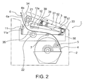
- FIG. 2 shows the double-sided thermal printer when the operating cover is slightly open.
- the double-sided thermal printer 1 has a basically rectangular box-shaped printer case 2, and an operating cover 3 that is attached to open and close to this printer case 2.
- the operating cover 3 can open and close between a substantially horizontal closed position 3A and an open position 3B where the operating cover 3 is standing up as indicated by the double-dot dash line in FIG. 1 .
- the roll paper 5 is a long web of thermal paper 6 wound into a roll.
- the roll paper 6 is, for example, double-sided thermal paper having thermo-sensitive surfaces 6a and 6b formed on the front and back sides.
- the thermal paper 6 is pulled up and off the roll paper 5 held in the roll paper storage compartment 4, passed the guide roller 7 and guided horizontally toward the front of the printer, and set pulled out from the paper exit 10 passed a back-side printing position 8 and a front-side printing position 9.
- a first thermal print head 11 and a first platen roller 21 are disposed at the front-side printing position 9.
- the thermal paper 6 is conveyed by the first platen roller 21 with the thermo-sensitive surface 6a on the front side pressed by the first platen roller 21 to the heat-emitting surface 11a of the first thermal print head 11 for printing on this front thermo-sensitive surface 6a.
- a second thermal print head 12 and second platen roller 22 are disposed to the back-side printing position 8.
- the thermal paper 6 is conveyed by the second platen roller 22 with the thermo-sensitive surface 6b on the back side pressed by the second platen roller 22 to the heat-emitting surface 12a of the second thermal print head 12 for printing on this back thermo-sensitive surface 6b.
- the first thermal print head 11, second platen roller 22, and guide roller 7 are disposed to the printer frame 30.
- the first platen roller 21 is disposed to a pivoting first arm 31 that is attached to the operating cover 3.
- the second thermal print head 12 is disposed to a second arm 32 that pivots in conjunction with the first arm 31.
- the base end part of the first arm 31 is supported rotatably on a horizontal shaft 33 that is attached to the printer frame 30 and extends horizontally widthwise to the printer.
- the first arm 31 can thus pivot on this horizontal shaft 33 from the substantially horizontal closed position 31A (first closed position) to the open position 31 B (first open position) indicated by the double-dot dash line in FIG. 1 .
- the first platen roller 21 is disposed horizontally widthwise to the printer at a position on the underside of the distal end part of the first arm 31.
- the first thermal print head 11 is attached at a position on the printer frame 30 side that is opposite the first platen roller 21 when the first arm 31 is closed.
- the first thermal print head 11 is disposed so that the heat-emitting surface 11a is vertical and the first platen roller 21 is pressed to the heat-emitting surface 11 a with a predetermined amount of pressure when the first arm 31 is closed.
- the paper transportation force can be increased when the winding angle of the thermal paper 6 around the first platen roller 21 is thus large.
- the trailing end part of the second arm 32 is similarly supported rotatably on a horizontal shaft 33, and can pivot on this horizontal shaft 33 from a substantially horizontal closed position 32A (second closed position) to the open position 32B (second open position) indicated by the double-dot dash line in FIG. 1 .
- the second thermal print head 12 is disposed horizontally widthwise to the printer at a position on the underside of the distal end part of the second arm 32 with the heat-emitting surface 12a of the second thermal print head 12 facing down.
- the second platen roller 22 is attached horizontally widthwise to the printer at a position on the printer frame 30 that is opposite the heat-emitting surface 12a of the second thermal print head 12 when the second arm 32 is closed.
- the heat-emitting surface 12a of the second thermal print head 12 is pressed against the second platen roller 22 with a predetermined amount of pressure.
- a latch mechanism that locks the operating cover 3 in the closed position is rendered between the first platen roller 21 and the printer frame 30.
- the latch mechanism has left and right locking levers 34 and left and right catch pins 35.
- the locking levers 34 are attached at both sides on the distal end part of the first arm 31 with an urging force applied thereto by a spring, and the catch pins 35 are affixed on the printer frame 30 side.
- the left and right locking levers 34 meet the left and right catch pins 35, and then ride over and catch the catch pins 35.
- a lever not shown is manually operated to disengage the locking levers 34 from the catch pins 35 and thereby unlock the latch.
- the first arm 31 and second arm 32 are constantly urged to open by torsion springs 36 and 37.
- the springs cause the operating cover 3 to open a certain amount as shown in FIG. 2 , thereby making opening the operating cover 3 easy.
- the arms open and close together while held at the open angle therebetween shown in FIG. 2 .
- a pressure spring 38 that urges the second arm 32 to the closed position is attached to the first arm 31.
- this pressure spring 38 contacts the spring receiver 39 rendered to the second arm 32.
- the second arm 32 is held in the closed position by the force of the pressure spring 38.
- the pressure spring 38 in this embodiment of at least one embodiment of the invention can slide from the position touching the spring receiver 39 to the position indicated by the dotted line in FIG. 2 .
- the second arm 32 is not pressed to the closed position by the force of the pressure spring 38 when the first arm 31 is closed, and is held floating in the open position by the force of the torsion spring 37.
- the second thermal print head 12 mounted on the second arm 32 is not pressed to the second platen roller 22, and is held in this floating position.
- the first arm 31 attached to the operating cover 3 also opens and the second arm 32 also opens in conjunction therewith.
- the top of the roll paper storage compartment 4 is open and the roll paper 5 can be replaced, for example.
- the first and second arms 31 and 32 also close. As shown in FIG. 2 , the first and second arms 31 and 32 pivot closed at a specific opening angle.
- the second thermal print head 12 mounted on the second arm 32 is therefore first pressed against the second platen roller 22 on the printer frame 30 side and the double-sided thermal paper 6 is held between the second thermal print head 12 and second platen roller 22.
- the first platen roller 21 mounted on the first arm 31 is then pressed against the first thermal print head 11 on the printer frame 30 side, and the double-sided thermal paper 6 is held between the first thermal print head 11 and first platen roller 21.
- the double-sided thermal paper 6 is first held between the second thermal print head 12 and second platen roller 22 at an upstream side position, and is then held between the first thermal print head 11 and first platen roller 21 on the downstream side. Therefore, if tension is held on the thermal paper 6 as the operating cover 3 is closed, there will be no slack in the thermal paper 6 between the back-side printing position 8 and the front-side printing position 9. Less time is therefore needed for the paper feed operation used to remove slack in the thermal paper 6 before printing. Problems such as a drop in print quality caused by the thermal paper 6 becoming skewed due to slack therefore do not occur.
- first platen roller 21 mounted on the first arm 31 it is also only necessary to position the first platen roller 21 mounted on the first arm 31 to the first thermal print head 11 on the printer frame 30 side, and to separately position the second thermal print head 12 mounted on the second arm 32 to the second platen roller 22 on the printer frame 30 side.
- the parts can therefore be positioned more precisely and positioning is also easier than in a construction having a thermal head and platen roller that require separately positioning to different parts disposed on a single arm.
- the first arm 31 After the second arm 32 reaches the closed position 32A, the first arm 31 reaches the closed position 31A and the operating cover 3 is locked closed by the latch mechanism.
- a single arm is closed to press the first thermal print head to the second platen roller and simultaneously press the second thermal print head to the first platen roller, a large amount of force is applied to lock the arm and the arm can be easily deformed. If the arm becomes deformed, there is a strong possibility that only one of the locking levers 34 disposed to both widthwise sides of the printer will catch the catch pin 35, the other locking lever 34 will not catch the catch pin 35, and the cover will be latched on only one side.
- the force applied to the first arm 31 increases gradually, strong force is applied only when locking, and at least one embodiment of the invention can therefore avoid latching on only one side.
- the paper transportation load can also be reduced and high speed printing enabled when the double-sided thermal printer 1 is used to print on common single-sided thermal paper having a thermo-sensitive surface formed on only one side.
- the pressure spring 38 of the first arm 31 is slid so that it does not contact the spring receiver 39 of the second arm 32 as shown in FIG. 3 .
- the second arm 32 will be urged in the opening direction by the torsion spring 37 even when the first arm 31 is locked in the closed position 31A, and will remain floating without reaching the closed position 32A.
- the second thermal print head 12 on the second arm 32 will not be pressed to the second platen roller 22 on the printer frame 30 side, and will be held floating away from the platen.
- the single-sided thermal paper 6A pulled from the roll paper 5 is therefore not held between the second thermal print head 12 and the second platen roller 22 at the back-side printing position 8 and is only held between the first thermal print head 11 and first platen roller 21 at the front-side printing position 9. Unnecessary pressure is therefore not applied, and the transportation load on the single-sided thermal paper 6A is lower.
- the paper transportation motor (not shown in the figure) can also be driven faster than during duplex printing, and high speed printing is possible.
- the mechanism stopping the second arm 32 from closing to the closed position 32A during simplex printing can be used as the mechanism stopping the second arm 32 from closing to the closed position 32A during simplex printing.
- the second arm 32 could also be closed to the closed position 32A and the second platen roller 22 on the printer frame 30 side could be made to escape. More specifically, the second platen roller 22 could be made to move to a position not in contact with the second thermal print head 12 on the second arm 32 side.
- the second arm 32 could also be rendered as a unit that can be installed to and removed from the horizontal shaft 33 on the printer frame 30 side, and the second arm could be removed for simplex printing.
- first and second arms 31 and 32 in the double-sided thermal printer 1 described above pivot on a common horizontal shaft 33.
- the first and second arms 31 and 32 can alternatively pivot on different horizontal shafts.
- the pivot axis of the first arm 31 can be determined by a horizontal shaft 33 disposed on the printer frame 30 side, and the pivot axis of the second arm 32 can be determined by a horizontal shaft 33A attached to the first arm 31.
- the pivot axis of the first arm 31 can be determined by a horizontal shaft 33 disposed on the printer frame 30 side, and the pivot axis of the second arm 32 can be determined by a separate horizontal shaft 33B also disposed on the printer frame 30 side.
- the first thermal print head 11 could be disposed to the first arm 31 with the first platen roller 21 disposed to the printer frame 30 side.
- the second platen roller 22 is mounted on the second arm 32 side, and the second thermal print head 12 is mounted on the printer frame 30 side.
- FIG. 1 to FIG. 3 show the thermal paper 6 being conveyed counterclockwise from the roll paper 5, but the orientation of the roll paper 5 can be reversed and the thermal paper 6 conveyed clockwise.
Abstract
Description
- The entire disclosure of Japanese Patent Application No.
2007-254266 filed on September 28, 2007 - The present invention relates to a thermal printer having two thermal print head and platen roller sets disposed along the thermal paper transportation path for printing on both the front and back sides of double-sided thermal paper.
- A thermal printer that prints on double-sided thermal paper having thermo-sensitive surfaces formed on both sides of the paper is disclosed in
U.S. Patent 6,784,906 . The disclosed thermal printer has a first print head and first platen supported on a first arm and a second platen opposing the first print head and a second print head opposing the first platen supported on a second arm installed on the printer frame side. When roll paper is pulled from a roll of double-sided thermal paper and the first arm is closed to the second arm, the double-sided thermal paper is set between the first print head and second platen on the upstream side of the paper transportation direction and between the second print head and the first platen on the downstream side in the transportation direction, the first print head opposes the front side of the double-sided thermal paper, and the second print head opposes the back side of the double-sided thermal paper. The front and back sides of the double-sided thermal paper can therefore be printed simultaneously. - However, the thermal printer disclosed in
U.S. Patent 6,784,906 fails to solve the following problems. - First, when the first arm closes to the second arm, the first print head and first platen carried on the first arm are simultaneously pressed to the respectively opposing second platen and second print head. As a result, even if the first arm is closed while pulling on the double-sided thermal paper so that there is no slack, the first and second platens which are free at this time may rotate due to the tension of the double-sided thermal paper because the double-sided thermal paper is simultaneously held between the first print head and the second platen on the upstream side and the second print head and first platen on the downstream side, and slack results easily between the first and second platens. If slack develops, the double-sided thermal paper may become skewed while being conveyed. An operation to remove the slack is therefore necessary.
- Second, the first print head and first platen on the first arm must be positioned to contact the second platen and second print head on the second arm during printer assembly, for example. This requires simultaneously positioning the two print head and platen sets, which makes positioning more difficult than when the first print head is positioned to the second platen and the first platen is separately and independently positioned to the second print head.
- Third, because there are two sets of print heads and platens, repulsion to the pressure applied to press the first print head to the second platen and repulsion to the pressure applied to press the second print head to the first platen both work when the first arm closes. This requires applying twice as much force to the first arm as when there is only one print head and platen set and a single print head is pressed to the platen. A strong operating force is therefore required to overcome twice the repulsion force when closing the first arm, and the first arm can be easily deformed by this strong operating force. When the cover to which the first arm is attached is closed to the printer frame side and an assembly that latches at both widthwise sides is used, deformation of the first arm when the cover closes can result in only one side engaging in the closed position and the other side not completely engaging in the closed position. The possibility is therefore high that the cover may be latched on only one side.
- Fourth, because two sets of print heads are always pressed against the opposing platens when the first arm is closed, the paper transportation load on the double-sided thermal paper passing therebetween is increased. Two sets of print heads are also always pressed against the double-sided thermal paper in the same way as when both sides are printed even if only one side of the paper is printed using one print head similarly to when single-sided thermal paper having a thermo-sensitive coating rendered on only one side of the thermal paper is printed. This creates the problem that printing in a manner that is optimal for printing on only one side is not possible.
- The thermal printer according to at least one embodiment of the invention solves the foregoing problems of the conventional thermal printer having two thermal print head and platen roller sets for printing on both sides of the printing media.
- A first aspect of at least one embodiment of the invention is a thermal printer including: a first thermal print head; a first platen roller; a second thermal print head; a second platen roller; a printer frame on which the first thermal print head and second platen roller are mounted; a first arm on which the first platen roller is mounted and which can move between a first closed position where the first platen roller is pressed to the first thermal print head, and a first open position where the first platen roller is separated from the first thermal print head; and a second arm on which the second thermal print head is mounted and which can move between a second closed position where the second thermal print head is pressed to the second platen roller and a second open position where the second thermal print head is separated from the second platen roller.
- A second aspect of at least one embodiment of the invention is a thermal printer including: a first thermal print head; a first platen roller; a second thermal print head; a second platen roller; a printer frame on which the first platen roller and second thermal print head are mounted; a first arm on which the first thermal print head is mounted and which can move between a first closed position where the first thermal print head is pressed to the first platen roller, and a first open position where the first thermal print head is separated from the first platen roller; and a second arm on which the second platen roller is mounted and which can move between a second closed position where the second platen roller is pressed to the second thermal print head and a second open position where the second platen roller is separated from the second thermal print head.
- A thermal printer according to at least one embodiment of the invention has a first platen roller or first thermal print head mounted on a first arm, and a second thermal print head or second platen roller mounted on a second arm. Two thermal print head and platen roller sets can be opened and closed by opening and closing these two arms. Positioning the parts is therefore simpler and more precise than a configuration in which one of the parts for two thermal print head and platen roller sets are mounted on a single arm. In addition, because little force is applied to each arm when closing the arms, the arms are prevented from latching closed on only one side.
- In a thermal printer according to another aspect of at least one embodiment of the invention, the second arm moves from the second open position to the second closed position when the first arm moves form the first open position to the first closed position; and the second arm moves from the second closed position to the second open position when the first arm moves from the first closed position to the first open position.
- By thus opening and closing the second arm in conjunction with the first arm, a construction having two arms can be operated in the same way as a construction having one arm.
- In a thermal printer according to another aspect of at least one embodiment of the invention, the second arm reaches the second closed position before the first arm reaches the first closed position when the first arm moves from the first open position to the first closed position.
- If the second arm on which the second thermal print head or the second platen roller located on the upstream side in the thermal paper transportation path reaches the closed position first, the thermal paper can be prevented from being held with slack between the two thermal print head and platen roller sets. If the first arm is closed while pulling the thermal paper to the downstream side in the transportation direction, for example, the second arm will close first and hold the thermal paper between the upstream thermal print head and platen roller so that when the first arm then closes while tension is applied to the thermal print head leader, the thermal paper will be held between the downstream side thermal print head and platen roller with no slack in the paper. The thermal paper can therefore be loaded for printing with no slack. A paper feed operation for removing slack is therefore not necessary, and the thermal paper can be conveyed without skewing caused by slack.
- In a thermal printer according to another aspect of at least one embodiment of the invention, the second arm can be set so that the second arm does not reach the second closed position even if the first arm moves to the first closed position. Alternatively, the second platen roller can be moved to a position where it will not contact the second thermal print head.
- If the second arm can be set so that it will not reach the second closed position regardless of the position of the first arm when printing on only one side of the thermal paper using only the first thermal print head and first platen roller mounted on the first arm and printer frame, the thermal paper will not be held with the predetermined pressure between the second thermal print head and second platen roller that are not being used. If the second platen roller is moved to the retracted position so that it does not contact the second thermal print head, the thermal paper will also not be held therebetween with the predetermined pressure. Unnecessary paper transportation load can therefore be reduced and high speed printing can be enabled.
- In a thermal printer according to another aspect of at least one embodiment of the invention, the second arm is removably attached to the printer frame or the first arm.
- This configuration enables reconfiguring the thermal printer for single-sided printing by removing the second arm.
- Further preferably, the thermal printer according to another aspect of at least one embodiment of the invention also has a roll paper storage compartment for storing roll paper having a long web of roll paper wound in a roll, and an operating cover that opens and closes to the roll paper storage compartment, and the operating cover is attached to the first arm.
- In a thermal printer according to another aspect of at least one embodiment of the invention, the first arm and the second arm pivot on the same pivot shaft attached to the printer frame.
- Alternatively, the first arm pivots on a first pivot shaft attached to the printer frame, and the second arm pivots on a second pivot shaft that is attached parallel to the first pivot shaft on the printer frame at a position that is different from the first pivot shaft.
- Further alternatively, the first arm pivots on a first pivot shaft attached to the printer frame, and the second arm pivots on a second pivot shaft attached to the first arm parallel to the first pivot shaft.
- Further preferably, a lock mechanism is disposed between the printer frame and at least one of the first arm and second arm. Because this lock mechanism can be engaged with less force than is required in a single arm configuration, latching on only one side can be prevented and the lock can be positively engaged.
- As described above, a thermal printer according to at least one embodiment of the invention has a first arm and a second arm connected to the printer frame, either the first thermal print head or the first platen roller is mounted on the first arm and the other is disposed to the printer frame, and either the second thermal print head or the second platen roller is mounted on the second arm and the other is disposed to the printer frame. Therefore, when the first arm is closed, the first thermal print head and first platen roller are pressed together, and when the second arm is closed, the second thermal print head and second platen roller are pressed together. Two arms are thus used to open and close two thermal print head and platen roller sets.
- As a result, the problems that occur with the thermal printer according to the related art, including the slack in the thermal paper that occurs in a conventional double-sided thermal printer having a single arm whereby two thermal print head and platen roller sets are simultaneously closed when the arm is closed, the difficulty positioning the thermal print heads and platen rollers, and latching only one side of the arm, do not occur.
- The double-sided thermal printer according to at least one embodiment of the invention can also be easily configured for double-sided or duplex printing and single-sided or simplex printing.
- Other objects and attainments together with a fuller understanding of the invention will become apparent and appreciated by referring to the following description and claims taken in conjunction with the accompanying drawings.
-
- FIG. 1
- describes a double-sided thermal printer according to at least one embodiment of the invention.
- FIG. 2
- shows the double-sided thermal printer shown in
FIG. 1 when the operating cover is slightly open. - FIG. 3
- shows the double-sided thermal printer shown in
FIG. 1 in the single-side print mode. - FIG. 4A, FIG. 4B, and FIG. 4C
- show the first and second arms at different pivot positions.
- FIG. 5
- shows an example in which the thermal print heads and platen rollers are attached at different positions.
- Preferred embodiments of a thermal printer according to at least one embodiment of the invention are described below with reference to the accompanying figures.
-
FIG. 1 describes a double-sided thermal printer according to a preferred embodiment of at least one embodiment of the invention, andFIG. 2 shows the double-sided thermal printer when the operating cover is slightly open. - The double-sided
thermal printer 1 has a basically rectangular box-shapedprinter case 2, and anoperating cover 3 that is attached to open and close to thisprinter case 2. Theoperating cover 3 can open and close between a substantially horizontalclosed position 3A and anopen position 3B where theoperating cover 3 is standing up as indicated by the double-dot dash line inFIG. 1 . - When the
operating cover 3 is open, the top end part of the rollpaper storage compartment 4 formed inside theprinter case 2 is open, and rollpaper 5 can be loaded from above into the rollpaper storage compartment 4. Theroll paper 5 is a long web ofthermal paper 6 wound into a roll. Theroll paper 6 is, for example, double-sided thermal paper having thermo-sensitive surfaces - The
thermal paper 6 is pulled up and off theroll paper 5 held in the rollpaper storage compartment 4, passed theguide roller 7 and guided horizontally toward the front of the printer, and set pulled out from thepaper exit 10 passed a back-side printing position 8 and a front-side printing position 9. - A first
thermal print head 11 and afirst platen roller 21 are disposed at the front-side printing position 9. Thethermal paper 6 is conveyed by thefirst platen roller 21 with the thermo-sensitive surface 6a on the front side pressed by thefirst platen roller 21 to the heat-emittingsurface 11a of the firstthermal print head 11 for printing on this front thermo-sensitive surface 6a. - A second
thermal print head 12 andsecond platen roller 22 are disposed to the back-side printing position 8. Thethermal paper 6 is conveyed by thesecond platen roller 22 with the thermo-sensitive surface 6b on the back side pressed by thesecond platen roller 22 to the heat-emittingsurface 12a of the secondthermal print head 12 for printing on this back thermo-sensitive surface 6b. - The first
thermal print head 11,second platen roller 22, and guideroller 7 are disposed to theprinter frame 30. Thefirst platen roller 21 is disposed to a pivotingfirst arm 31 that is attached to theoperating cover 3. The secondthermal print head 12 is disposed to asecond arm 32 that pivots in conjunction with thefirst arm 31. - The base end part of the
first arm 31 is supported rotatably on ahorizontal shaft 33 that is attached to theprinter frame 30 and extends horizontally widthwise to the printer. Thefirst arm 31 can thus pivot on thishorizontal shaft 33 from the substantially horizontalclosed position 31A (first closed position) to theopen position 31 B (first open position) indicated by the double-dot dash line inFIG. 1 . Thefirst platen roller 21 is disposed horizontally widthwise to the printer at a position on the underside of the distal end part of thefirst arm 31. - The first
thermal print head 11 is attached at a position on theprinter frame 30 side that is opposite thefirst platen roller 21 when thefirst arm 31 is closed. The firstthermal print head 11 is disposed so that the heat-emittingsurface 11a is vertical and thefirst platen roller 21 is pressed to the heat-emittingsurface 11 a with a predetermined amount of pressure when thefirst arm 31 is closed. The paper transportation force can be increased when the winding angle of thethermal paper 6 around thefirst platen roller 21 is thus large. - The trailing end part of the
second arm 32 is similarly supported rotatably on ahorizontal shaft 33, and can pivot on thishorizontal shaft 33 from a substantially horizontalclosed position 32A (second closed position) to theopen position 32B (second open position) indicated by the double-dot dash line inFIG. 1 . The secondthermal print head 12 is disposed horizontally widthwise to the printer at a position on the underside of the distal end part of thesecond arm 32 with the heat-emittingsurface 12a of the secondthermal print head 12 facing down. - The
second platen roller 22 is attached horizontally widthwise to the printer at a position on theprinter frame 30 that is opposite the heat-emittingsurface 12a of the secondthermal print head 12 when thesecond arm 32 is closed. When thesecond arm 32 is closed, the heat-emittingsurface 12a of the secondthermal print head 12 is pressed against thesecond platen roller 22 with a predetermined amount of pressure. - A latch mechanism that locks the
operating cover 3 in the closed position is rendered between thefirst platen roller 21 and theprinter frame 30. The latch mechanism has left and right locking levers 34 and left and right catch pins 35. The locking levers 34 are attached at both sides on the distal end part of thefirst arm 31 with an urging force applied thereto by a spring, and the catch pins 35 are affixed on theprinter frame 30 side. When thefirst arm 31 is open and pushed to theclosed position 31A, the left and right locking levers 34 meet the left and right catch pins 35, and then ride over and catch the catch pins 35. A lever not shown is manually operated to disengage the locking levers 34 from the catch pins 35 and thereby unlock the latch. - The
first arm 31 andsecond arm 32 are constantly urged to open by torsion springs 36 and 37. When the latch is unlocked, the springs cause theoperating cover 3 to open a certain amount as shown inFIG. 2 , thereby making opening theoperating cover 3 easy. After the latch is unlocked and thefirst arm 31 andsecond arm 32 are opened by the force of the springs, the arms open and close together while held at the open angle therebetween shown inFIG. 2 . - A
pressure spring 38 that urges thesecond arm 32 to the closed position is attached to thefirst arm 31. When thefirst arm 31 is pressed in the closing direction from the position shown inFIG. 2 , thispressure spring 38 contacts thespring receiver 39 rendered to thesecond arm 32. As a result, thesecond arm 32 is held in the closed position by the force of thepressure spring 38. - The
pressure spring 38 in this embodiment of at least one embodiment of the invention can slide from the position touching thespring receiver 39 to the position indicated by the dotted line inFIG. 2 . When thepressure spring 38 is slid, thesecond arm 32 is not pressed to the closed position by the force of thepressure spring 38 when thefirst arm 31 is closed, and is held floating in the open position by the force of thetorsion spring 37. As a result, the secondthermal print head 12 mounted on thesecond arm 32 is not pressed to thesecond platen roller 22, and is held in this floating position. - The operational effect of this double-sided
thermal printer 1 is described next. - When the
operating cover 3 is unlocked and theoperating cover 3 is opened from theclosed position 3A indicated by the solid line inFIG. 1 to theopen position 3B indicated by the double-dot dash line, thefirst arm 31 attached to theoperating cover 3 also opens and thesecond arm 32 also opens in conjunction therewith. As a result, the top of the rollpaper storage compartment 4 is open and theroll paper 5 can be replaced, for example. - When the
roll paper 5 is replaced, a specific length of the double-sidedthermal paper 6 is pulled from thenew roll paper 5 placed in the rollpaper storage compartment 4, and theoperating cover 3 is closed while tension is held on thethermal paper 6 that was pulled out. When theoperating cover 3 is closed, the first andsecond arms FIG. 2 , the first andsecond arms thermal print head 12 mounted on thesecond arm 32 is therefore first pressed against thesecond platen roller 22 on theprinter frame 30 side and the double-sidedthermal paper 6 is held between the secondthermal print head 12 andsecond platen roller 22. Thefirst platen roller 21 mounted on thefirst arm 31 is then pressed against the firstthermal print head 11 on theprinter frame 30 side, and the double-sidedthermal paper 6 is held between the firstthermal print head 11 andfirst platen roller 21. - When the
operating cover 3 is thus closed, the double-sidedthermal paper 6 is first held between the secondthermal print head 12 andsecond platen roller 22 at an upstream side position, and is then held between the firstthermal print head 11 andfirst platen roller 21 on the downstream side. Therefore, if tension is held on thethermal paper 6 as theoperating cover 3 is closed, there will be no slack in thethermal paper 6 between the back-side printing position 8 and the front-side printing position 9. Less time is therefore needed for the paper feed operation used to remove slack in thethermal paper 6 before printing. Problems such as a drop in print quality caused by thethermal paper 6 becoming skewed due to slack therefore do not occur. - It is also only necessary to position the
first platen roller 21 mounted on thefirst arm 31 to the firstthermal print head 11 on theprinter frame 30 side, and to separately position the secondthermal print head 12 mounted on thesecond arm 32 to thesecond platen roller 22 on theprinter frame 30 side. The parts can therefore be positioned more precisely and positioning is also easier than in a construction having a thermal head and platen roller that require separately positioning to different parts disposed on a single arm. - After the
second arm 32 reaches theclosed position 32A, thefirst arm 31 reaches theclosed position 31A and theoperating cover 3 is locked closed by the latch mechanism. When a single arm is closed to press the first thermal print head to the second platen roller and simultaneously press the second thermal print head to the first platen roller, a large amount of force is applied to lock the arm and the arm can be easily deformed. If the arm becomes deformed, there is a strong possibility that only one of the locking levers 34 disposed to both widthwise sides of the printer will catch thecatch pin 35, the other lockinglever 34 will not catch thecatch pin 35, and the cover will be latched on only one side. - By using two arms, however, the force applied to the
first arm 31 increases gradually, strong force is applied only when locking, and at least one embodiment of the invention can therefore avoid latching on only one side. - The paper transportation load can also be reduced and high speed printing enabled when the double-sided
thermal printer 1 is used to print on common single-sided thermal paper having a thermo-sensitive surface formed on only one side. - For simplex printing, the
pressure spring 38 of thefirst arm 31 is slid so that it does not contact thespring receiver 39 of thesecond arm 32 as shown inFIG. 3 . When theoperating cover 3 is closed after thus sliding thepressure spring 38, thesecond arm 32 will be urged in the opening direction by thetorsion spring 37 even when thefirst arm 31 is locked in theclosed position 31A, and will remain floating without reaching theclosed position 32A. As a result, the secondthermal print head 12 on thesecond arm 32 will not be pressed to thesecond platen roller 22 on theprinter frame 30 side, and will be held floating away from the platen. - The single-sided
thermal paper 6A pulled from theroll paper 5 is therefore not held between the secondthermal print head 12 and thesecond platen roller 22 at the back-side printing position 8 and is only held between the firstthermal print head 11 andfirst platen roller 21 at the front-side printing position 9. Unnecessary pressure is therefore not applied, and the transportation load on the single-sidedthermal paper 6A is lower. The paper transportation motor (not shown in the figure) can also be driven faster than during duplex printing, and high speed printing is possible. - Various means can be used as the mechanism stopping the
second arm 32 from closing to theclosed position 32A during simplex printing. Thesecond arm 32 could also be closed to theclosed position 32A and thesecond platen roller 22 on theprinter frame 30 side could be made to escape. More specifically, thesecond platen roller 22 could be made to move to a position not in contact with the secondthermal print head 12 on thesecond arm 32 side. - The
second arm 32 could also be rendered as a unit that can be installed to and removed from thehorizontal shaft 33 on theprinter frame 30 side, and the second arm could be removed for simplex printing. - As shown in
FIG. 4A , the first andsecond arms thermal printer 1 described above pivot on a commonhorizontal shaft 33. The first andsecond arms - As shown in
FIG. 4B , for example, the pivot axis of thefirst arm 31 can be determined by ahorizontal shaft 33 disposed on theprinter frame 30 side, and the pivot axis of thesecond arm 32 can be determined by ahorizontal shaft 33A attached to thefirst arm 31. - Further alternatively, as show in
FIG. 4C , the pivot axis of thefirst arm 31 can be determined by ahorizontal shaft 33 disposed on theprinter frame 30 side, and the pivot axis of thesecond arm 32 can be determined by a separatehorizontal shaft 33B also disposed on theprinter frame 30 side. - As shown in
FIG. 5 , the firstthermal print head 11 could be disposed to thefirst arm 31 with thefirst platen roller 21 disposed to theprinter frame 30 side. In this configuration thesecond platen roller 22 is mounted on thesecond arm 32 side, and the secondthermal print head 12 is mounted on theprinter frame 30 side. -
FIG. 1 to FIG. 3 show thethermal paper 6 being conveyed counterclockwise from theroll paper 5, but the orientation of theroll paper 5 can be reversed and thethermal paper 6 conveyed clockwise. - At least one embodiment of the invention being thus described, it will be obvious that it may be varied in many ways. Such variations are not to be regarded as a departure from the spirit and scope of at least one embodiment of the invention, and all such modifications as would be obvious to one skilled in the art are intended to be included within the scope of the following claims.
Claims (12)
- A thermal printer comprising:first printing means having a first thermal print head (11) as a first one and a first platen roller (21) as a second one of two members;second printing means having a second thermal print head (12) as a first one and a second platen roller (22) as a second one of two members;a printer frame (30) on which one member of the first printing means (11, 21) and one member of the second printing means (12, 22) are mounted;a first arm (31) on which the other member of the first printing means (11, 21) is mounted and which is arranged to move between a first closed position (31A) where the first platen roller (21) is pressed to the first thermal print head (11), and a first open position (31B) where the first platen roller (21) is separated from the first thermal print head (11); anda second arm (32) on which the other member of the second printing means (12, 22) is mounted and which is arranged to move between a second closed position (32A) where the second thermal print head (12) is pressed to the second platen roller (22) and a second open position (32B) where the second thermal print head (12) is separated from the second platen roller (22).
- The thermal printer described in claim 1, wherein the second arm (32) is removably attached to the printer frame (30) or to the first arm (31).
- The thermal printer described in any one of the preceding claims, wherein the first arm (31) and the second arm (32) are both pivotally supported on the printer frame (30).
- The thermal printer described in claim 3, wherein the first arm (31) and the second arm (32) are both pivotally supported on the same pivot shaft (33) that is attached to the printer frame (30).
- The thermal printer described in claim 3, wherein:the first arm (31) is pivotally supported on a first pivot shaft (33) attached to the printer frame (30); andthe second arm (32) is pivotally supported on a second pivot shaft (33B) that is attached in parallel to the first pivot shaft (33) to the printer frame (30) at a position different from that of the first pivot shaft (33).
- The thermal printer described in claim 1 or 2, wherein:the first arm (31) is pivotally supported on a first pivot shaft (33) attached to the printer frame (30); andthe second arm (32) is pivotally supported on a second pivot shaft (33A) attached to the first arm (31) in parallel to the first pivot shaft (33).
- The thermal printer described in any one of the preceding claims, wherein a lock mechanism is disposed between the printer frame (30) and at least one of the first arm (31) and second arm (32).
- The thermal printer described in any one of the preceding claims, wherein the second arm (32) is linked to the first arm (31) such as to move from the second open position (32B) to the second closed position (32A) when the first arm (31) moves from the first open position (31B) to the first closed position (31A) and to move from the second closed position (32A) to the second open position (32B) when the first arm (31) moves from the first closed position (31A) to the first open position (31 B).
- The thermal printer described in claim 8, wherein the second arm (32) is linked to the first arm (31) in such a way that the second arm (32) reaches the second closed position (32A) before the first arm (31) reaches the first closed position (31A) when the first arm (31) moves from the first open position (31B) to the first closed position (31A).
- The thermal printer described in any one of claims 1 to 7, further comprising:a pressure member (38) attached to the first arm (31) so as to be movable relative to the first arm (31) between an active position and an inactive position;wherein the pressure member (38), in its active position, is arranged to engage the second arm (32) so as to press the second arm (32) to the second closed position (32A), while the pressure member (38) is disengaged from the second arm (32) in its inactive position.
- The thermal printer described in claim 10, further comprising:an urging member (37) arranged to act between the printer frame (30) and the second arm (32) so as to urge the second arm (32) towards the second open position (32B);the urging member being adapted to keep the second arm (32) away from the second closed position (32A), irrespective of the position of the first arm (31), when the pressure member (38) is in its inactive position.
- The thermal printer described in any one of the preceding claims, further comprising:a roll paper storage compartment (4) for storing roll paper having a long web of roll paper wound to a roll; andan operating cover (3) adapted to open and close the roll paper storage compartment;wherein the operating cover (3) is attached to the first arm (31).
Applications Claiming Priority (1)
| Application Number | Priority Date | Filing Date | Title |
|---|---|---|---|
| JP2007254266A JP4910965B2 (en) | 2007-09-28 | 2007-09-28 | Thermal printer |
Publications (3)
| Publication Number | Publication Date |
|---|---|
| EP2042327A2 true EP2042327A2 (en) | 2009-04-01 |
| EP2042327A3 EP2042327A3 (en) | 2009-08-12 |
| EP2042327B1 EP2042327B1 (en) | 2018-01-17 |
Family
ID=40193582
Family Applications (1)
| Application Number | Title | Priority Date | Filing Date |
|---|---|---|---|
| EP08016822.2A Expired - Fee Related EP2042327B1 (en) | 2007-09-28 | 2008-09-25 | Thermal printer |
Country Status (5)
| Country | Link |
|---|---|
| US (1) | US8139093B2 (en) |
| EP (1) | EP2042327B1 (en) |
| JP (1) | JP4910965B2 (en) |
| KR (1) | KR100989223B1 (en) |
| CN (1) | CN101396925B (en) |
Cited By (3)
| Publication number | Priority date | Publication date | Assignee | Title |
|---|---|---|---|---|
| CN102463746A (en) * | 2010-11-19 | 2012-05-23 | 山东新北洋信息技术股份有限公司 | Print head assembly and printer having same |
| EP2511100A1 (en) * | 2011-04-11 | 2012-10-17 | Wincor Nixdorf International GmbH | Double-sided printer for printing receipts on thermal paper |
| US11325405B2 (en) * | 2019-01-29 | 2022-05-10 | Fujitsu Component Limited | Printer with print head and support having head spring that urges print head |
Families Citing this family (10)
| Publication number | Priority date | Publication date | Assignee | Title |
|---|---|---|---|---|
| JP5001909B2 (en) * | 2008-06-26 | 2012-08-15 | 株式会社サトー知識財産研究所 | Cutting device |
| JP2011201017A (en) * | 2010-03-24 | 2011-10-13 | Seiko Epson Corp | Printer |
| CN101830125A (en) * | 2010-06-11 | 2010-09-15 | 山东新北洋信息技术股份有限公司 | Double-sided printer and control method thereof |
| EP2765005B1 (en) * | 2011-10-07 | 2017-12-06 | Fujitsu Component Limited | Printer device |
| JP2014040014A (en) * | 2012-08-21 | 2014-03-06 | Toshiba Tec Corp | Printing device and printing method |
| JP6135073B2 (en) * | 2012-09-01 | 2017-05-31 | 株式会社リコー | Image forming apparatus |
| CN103640340B (en) * | 2013-12-05 | 2016-09-14 | 北京亿赫伟信科技发展有限公司 | Thermal transfer printer |
| US9744784B1 (en) | 2016-02-05 | 2017-08-29 | Zih Corp. | Printhead carriers and adapters |
| JP7218591B2 (en) * | 2019-01-30 | 2023-02-07 | ブラザー工業株式会社 | Layer transfer device |
| CN113561664B (en) * | 2021-07-20 | 2022-11-22 | 珠海趣印科技有限公司 | Fixing structure of thermosensitive plate and thermosensitive printer |
Citations (4)
| Publication number | Priority date | Publication date | Assignee | Title |
|---|---|---|---|---|
| JPH0351149A (en) | 1989-07-20 | 1991-03-05 | Fujitsu General Ltd | Thermal transfer printer |
| US5806999A (en) | 1994-10-28 | 1998-09-15 | Nisca Corporation | Double-side printing system |
| US5961228A (en) | 1997-08-22 | 1999-10-05 | Paxar Corporation | Modular printer |
| WO2004058508A2 (en) | 2002-12-23 | 2004-07-15 | Polaroid Corporation | Thermal printer assembly |
Family Cites Families (18)
| Publication number | Priority date | Publication date | Assignee | Title |
|---|---|---|---|---|
| JPH0679855B2 (en) * | 1986-10-15 | 1994-10-12 | 株式会社セコニツク | Recording device |
| JP2720615B2 (en) * | 1991-03-27 | 1998-03-04 | 松下電器産業株式会社 | Thermal printer |
| JPH0550703A (en) | 1991-08-22 | 1993-03-02 | Mitsubishi Electric Corp | Thermal head device |
| JPH07290798A (en) * | 1994-04-28 | 1995-11-07 | Tamura Seisakusho Co Ltd | Thermal printer |
| JP3309038B2 (en) * | 1995-09-29 | 2002-07-29 | アンリツ株式会社 | Thermal head holding structure |
| JPH1076713A (en) | 1996-09-03 | 1998-03-24 | Sony Corp | Perfecting printer |
| US5886726A (en) * | 1997-02-10 | 1999-03-23 | Datacard Corporation | Thermal print head module and method for using |
| JPH1120214A (en) * | 1997-07-02 | 1999-01-26 | Tec Corp | Thermal printer |
| JPH11286147A (en) | 1998-04-02 | 1999-10-19 | Nec Yonezawa Ltd | Perfecting mechanism |
| JP2000052614A (en) | 1998-08-07 | 2000-02-22 | Toshiba Tec Corp | Printer |
| JP2000127554A (en) * | 1998-10-23 | 2000-05-09 | Fujitsu Takamisawa Component Ltd | Thermal printer |
| JP2002240358A (en) * | 2001-02-19 | 2002-08-28 | Funai Electric Co Ltd | Thermal recorder |
| US6784906B2 (en) * | 2001-12-18 | 2004-08-31 | Ncr Corporation | Direct thermal printer |
| US7254325B2 (en) * | 2003-05-06 | 2007-08-07 | Fujitsu Limited | Method and system for optical performance monitoring |
| JP2006051734A (en) | 2004-08-13 | 2006-02-23 | Nidec Copal Corp | Thermal printer |
| US7710442B2 (en) * | 2006-03-07 | 2010-05-04 | Ncr Corporation | Two-sided thermal print configurations |
| US7828490B2 (en) * | 2006-05-31 | 2010-11-09 | Toshiba Tec Kabushiki Kaisha | Printing apparatus including a cover holding a thermal head and a platen roller on a hinged frame |
| JP2007320121A (en) | 2006-05-31 | 2007-12-13 | Toshiba Tec Corp | Thermal printer for perfecting printing and method for holding thermal head |
-
2007
- 2007-09-28 JP JP2007254266A patent/JP4910965B2/en not_active Expired - Fee Related
-
2008
- 2008-09-24 US US12/237,125 patent/US8139093B2/en not_active Expired - Fee Related
- 2008-09-25 EP EP08016822.2A patent/EP2042327B1/en not_active Expired - Fee Related
- 2008-09-26 CN CN2008101610856A patent/CN101396925B/en not_active Expired - Fee Related
- 2008-09-26 KR KR1020080094495A patent/KR100989223B1/en active IP Right Grant
Patent Citations (4)
| Publication number | Priority date | Publication date | Assignee | Title |
|---|---|---|---|---|
| JPH0351149A (en) | 1989-07-20 | 1991-03-05 | Fujitsu General Ltd | Thermal transfer printer |
| US5806999A (en) | 1994-10-28 | 1998-09-15 | Nisca Corporation | Double-side printing system |
| US5961228A (en) | 1997-08-22 | 1999-10-05 | Paxar Corporation | Modular printer |
| WO2004058508A2 (en) | 2002-12-23 | 2004-07-15 | Polaroid Corporation | Thermal printer assembly |
Cited By (6)
| Publication number | Priority date | Publication date | Assignee | Title |
|---|---|---|---|---|
| CN102463746A (en) * | 2010-11-19 | 2012-05-23 | 山东新北洋信息技术股份有限公司 | Print head assembly and printer having same |
| EP2511100A1 (en) * | 2011-04-11 | 2012-10-17 | Wincor Nixdorf International GmbH | Double-sided printer for printing receipts on thermal paper |
| WO2012140030A1 (en) * | 2011-04-11 | 2012-10-18 | Wincor Nixdorf International Gmbh | Double-sided printer for printing receipts on thermal paper |
| US20140049592A1 (en) * | 2011-04-11 | 2014-02-20 | Wincor Nixdorf International Gmbh | Double-sided printer for printing receipts on thermal paper |
| US10576755B2 (en) | 2011-04-11 | 2020-03-03 | Wincor Nixdorf International Gmbh | Double-sided printer for printing receipts on thermal paper |
| US11325405B2 (en) * | 2019-01-29 | 2022-05-10 | Fujitsu Component Limited | Printer with print head and support having head spring that urges print head |
Also Published As
| Publication number | Publication date |
|---|---|
| JP4910965B2 (en) | 2012-04-04 |
| EP2042327A3 (en) | 2009-08-12 |
| CN101396925B (en) | 2010-12-15 |
| CN101396925A (en) | 2009-04-01 |
| KR20090033078A (en) | 2009-04-01 |
| US8139093B2 (en) | 2012-03-20 |
| EP2042327B1 (en) | 2018-01-17 |
| JP2009083218A (en) | 2009-04-23 |
| KR100989223B1 (en) | 2010-10-20 |
| US20090086006A1 (en) | 2009-04-02 |
Similar Documents
| Publication | Publication Date | Title |
|---|---|---|
| US8139093B2 (en) | Thermal printer | |
| US6789969B2 (en) | Printer | |
| EP1108556B1 (en) | Printer | |
| JP5106238B2 (en) | Printer with cutter | |
| US8287198B2 (en) | Printer | |
| JP2010099852A (en) | Printer with cutter | |
| JP2012030441A (en) | Feeding apparatus | |
| EP1000760B1 (en) | Printer | |
| US11285743B2 (en) | Printer | |
| JP4370730B2 (en) | Printing paper transport apparatus, control method thereof, and program | |
| EP2368717B1 (en) | Printer | |
| JP3700461B2 (en) | Printer | |
| US8550734B2 (en) | Transportation guide mechanism and recording device having the same | |
| JP5103970B2 (en) | Printer device | |
| JP4858267B2 (en) | Printer device | |
| JP4661591B2 (en) | Printer | |
| JP4905218B2 (en) | Printer device | |
| JP3704945B2 (en) | Printer | |
| JP3743157B2 (en) | Printer | |
| JP2023172780A (en) | Printer | |
| JP2004196498A (en) | Roll sheet fitting mechanism | |
| JP2019167219A (en) | Sheet guide device and printing device | |
| JP2008238487A (en) | Printer apparatus or lamination apparatus |
Legal Events
| Date | Code | Title | Description |
|---|---|---|---|
| PUAI | Public reference made under article 153(3) epc to a published international application that has entered the european phase |
Free format text: ORIGINAL CODE: 0009012 |
|
| AK | Designated contracting states |
Kind code of ref document: A2 Designated state(s): AT BE BG CH CY CZ DE DK EE ES FI FR GB GR HR HU IE IS IT LI LT LU LV MC MT NL NO PL PT RO SE SI SK TR |
|
| AX | Request for extension of the european patent |
Extension state: AL BA MK RS |
|
| PUAL | Search report despatched |
Free format text: ORIGINAL CODE: 0009013 |
|
| AK | Designated contracting states |
Kind code of ref document: A3 Designated state(s): AT BE BG CH CY CZ DE DK EE ES FI FR GB GR HR HU IE IS IT LI LT LU LV MC MT NL NO PL PT RO SE SI SK TR |
|
| AX | Request for extension of the european patent |
Extension state: AL BA MK RS |
|
| 17P | Request for examination filed |
Effective date: 20100119 |
|
| AKX | Designation fees paid |
Designated state(s): DE FR GB IT |
|
| GRAP | Despatch of communication of intention to grant a patent |
Free format text: ORIGINAL CODE: EPIDOSNIGR1 |
|
| INTG | Intention to grant announced |
Effective date: 20170728 |
|
| GRAS | Grant fee paid |
Free format text: ORIGINAL CODE: EPIDOSNIGR3 |
|
| GRAA | (expected) grant |
Free format text: ORIGINAL CODE: 0009210 |
|
| AK | Designated contracting states |
Kind code of ref document: B1 Designated state(s): DE FR GB IT |
|
| REG | Reference to a national code |
Ref country code: GB Ref legal event code: FG4D |
|
| REG | Reference to a national code |
Ref country code: DE Ref legal event code: R096 Ref document number: 602008053761 Country of ref document: DE |
|
| REG | Reference to a national code |
Ref country code: FR Ref legal event code: PLFP Year of fee payment: 11 |
|
| REG | Reference to a national code |
Ref country code: DE Ref legal event code: R097 Ref document number: 602008053761 Country of ref document: DE |
|
| PG25 | Lapsed in a contracting state [announced via postgrant information from national office to epo] |
Ref country code: IT Free format text: LAPSE BECAUSE OF FAILURE TO SUBMIT A TRANSLATION OF THE DESCRIPTION OR TO PAY THE FEE WITHIN THE PRESCRIBED TIME-LIMIT Effective date: 20180117 |
|
| PLBE | No opposition filed within time limit |
Free format text: ORIGINAL CODE: 0009261 |
|
| STAA | Information on the status of an ep patent application or granted ep patent |
Free format text: STATUS: NO OPPOSITION FILED WITHIN TIME LIMIT |
|
| REG | Reference to a national code |
Ref country code: DE Ref legal event code: R082 Ref document number: 602008053761 Country of ref document: DE Representative=s name: MERH-IP MATIAS ERNY REICHL HOFFMANN PATENTANWA, DE |
|
| 26N | No opposition filed |
Effective date: 20181018 |
|
| PGFP | Annual fee paid to national office [announced via postgrant information from national office to epo] |
Ref country code: DE Payment date: 20200916 Year of fee payment: 13 Ref country code: FR Payment date: 20200812 Year of fee payment: 13 Ref country code: GB Payment date: 20200916 Year of fee payment: 13 |
|
| REG | Reference to a national code |
Ref country code: DE Ref legal event code: R119 Ref document number: 602008053761 Country of ref document: DE |
|
| GBPC | Gb: european patent ceased through non-payment of renewal fee |
Effective date: 20210925 |
|
| PG25 | Lapsed in a contracting state [announced via postgrant information from national office to epo] |
Ref country code: GB Free format text: LAPSE BECAUSE OF NON-PAYMENT OF DUE FEES Effective date: 20210925 Ref country code: FR Free format text: LAPSE BECAUSE OF NON-PAYMENT OF DUE FEES Effective date: 20210930 Ref country code: DE Free format text: LAPSE BECAUSE OF NON-PAYMENT OF DUE FEES Effective date: 20220401 |