EP2045186A1 - Positioning system for aerial refueling - Google Patents
Positioning system for aerial refueling Download PDFInfo
- Publication number
- EP2045186A1 EP2045186A1 EP07117537A EP07117537A EP2045186A1 EP 2045186 A1 EP2045186 A1 EP 2045186A1 EP 07117537 A EP07117537 A EP 07117537A EP 07117537 A EP07117537 A EP 07117537A EP 2045186 A1 EP2045186 A1 EP 2045186A1
- Authority
- EP
- European Patent Office
- Prior art keywords
- aircraft
- positioning system
- signal
- drogue
- receiver
- Prior art date
- Legal status (The legal status is an assumption and is not a legal conclusion. Google has not performed a legal analysis and makes no representation as to the accuracy of the status listed.)
- Granted
Links
- 239000000446 fuel Substances 0.000 claims abstract description 4
- 239000000523 sample Substances 0.000 claims description 26
- 230000003287 optical effect Effects 0.000 claims description 9
- 239000003086 colorant Substances 0.000 claims description 3
- 238000010586 diagram Methods 0.000 description 2
- 238000000034 method Methods 0.000 description 2
- 238000005202 decontamination Methods 0.000 description 1
- 230000003588 decontaminative effect Effects 0.000 description 1
- XLYOFNOQVPJJNP-UHFFFAOYSA-N water Substances O XLYOFNOQVPJJNP-UHFFFAOYSA-N 0.000 description 1
Images


Classifications
-
- B—PERFORMING OPERATIONS; TRANSPORTING
- B64—AIRCRAFT; AVIATION; COSMONAUTICS
- B64D—EQUIPMENT FOR FITTING IN OR TO AIRCRAFT; FLIGHT SUITS; PARACHUTES; ARRANGEMENTS OR MOUNTING OF POWER PLANTS OR PROPULSION TRANSMISSIONS IN AIRCRAFT
- B64D39/00—Refuelling during flight
Definitions
- This invention relates to a positioning system for areal refueling of aircraft, such as unmanned aircraft or aircraft with a pilot flying the aircraft.
- Aerial refueling is used to extend the range of aircraft and is especially employed by the military.
- a flying boom or a hose with a drogue is extended from a tanker plane. If a flying boom is used a boom operator in the tanker plane steers the boom into a receiving probe or a refueling receptacle of the aircraft to be refueled.
- a hose and drogue system When a hose and drogue system is used the pilot of the aircraft to be refueled flies the receiving probe into the drogue.
- Several hose and drogue units may be installed on the tanker plane so that several aircraft can be refueled simultaneously.
- Flying the aircraft to be refueled in order to connect the receiving probe with the drogue is often a complicating and demanding task for the pilot. Also, it is a complicated task for the boom operator to connect the flying boom with the aircraft to be refueled. Over open water it is sometime necessary to refuel the aircraft in order to arrive to a destination airfield and an unsuccessful connection between the aircraft and the tanker plane results in loosing the aircraft to be refueled due to engine stop.
- Document US-B1-6,604,711 discloses an autonomous system for the aerial refueling or decontamination of unmanned airborne vehicles, in which a motor operates a hose reel for positioning of the drogue. Also, aerodynamic lifting surfaces and radial thrust on the drogue are used for motion control of the drogue.
- a radio transponder is arranged on the tanker plane for transmitting signals to and receiving signals from a transponder arranged on the unmanned aircraft. The signals received from the unmanned aircraft indicate the relative positions between the aircraft and the tanker plane and is used for controlling the drogue.
- One drawback with the known aerial refueling system is the dependence between the tanker aircraft and the unmanned aircraft to be refueled. Not any unmanned aircraft may be refueled by the tanker aircraft.
- Another drawback with the known system is that the likelihood for an error in the system increases when using a wireless data connection in both direction between the tanker plane and the aircraft to be refueled. Time lag in the data link between the tanker plane and the aircraft to be refueled may also occur.
- the objective problem to be solved by the present invention is to provide a positioning system for aerial refueling with improved accuracy and reliability.
- Another objective problem to be solved by the present invention is to achieve a positioning system for aerial refueling which is compatible with any aircraft to be refueled.
- optical signals from the drogue are detected by the receiver on the aircraft.
- the optical signals may be a pattern in different colours or black and white fields, light from emitting diodes, infra red light or laser arranged on the drogue or nozzle.
- the receiver detects the signals and processes them.
- the aircraft is manoeuvred by a control unit to an end position for connecting the probe with the drogue or the nozzle with the receptacle.
- acoustic signals from the drogue are detected by the receiver on the aircraft.
- the acoustic signals may have a specific frequency emitted from the drogue or nozzle.
- the receiver detects the signals and processes them.
- the aircraft is manoeuvred by a control unit to an end position for connecting the probe with the drogue or the nozzle with the receptacle.
- Both position systems with optical and acoustic signals could be made compatible to any aircraft which is provided with a receiver for receiving optical and/or acoustic signals.
- Fig. 1 is a schematic view of an aerial refueling with a positioning system according to the invention using a probe and drogue
- fig. 2 is a first embodiment of a positioning system according to the invention
- fig. 3 is a second embodiment of a positioning system according to the invention.
- fig. 4 is a third embodiment of a positioning system according to the invention.
- fig. 5 is a schematic view of an aerial refueling with a positioning system according to the invention using a receptacle and a boom nozzle, and
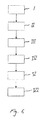
- fig. 6 is a block diagram of the positioning system according to the invention.
- Fig. 1 is a schematic view of an aerial refueling with a positioning system 1 according to the invention.
- a hose 2 with a drogue 4 is extended from a tanker plane 6.
- An aircraft 8 to be refueled is provided with a receiving probe 10 which is arranged to be connected to the drogue 4.
- the probe 10 and drogue 4 are adapted to feed fuel from the tanker plane 6 to the aircraft 8.
- a receiving probe 10 and drogue 4 are adapted to feed fuel from the tanker plane 6 to the aircraft 8.
- the drogue 4 is of a substantially circular, conical shape with a substantially circular surface 12 facing the aircraft 8 to be refueled.
- the positioning system 1 comprises a receiver 14 arranged on the aircraft 8 to receive signals from the drogue 4.
- the receiver 14 is mounted on the probe 10.
- the receiver 14 could be mounted at any suitable location on the aircraft 8.
- a control unit 16 on the aircraft 8 controls the aircraft 8 depending on the signals to steer the aircraft 8 to an end position for connecting the probe 10 with the drogue 4.
- the control unit 16 is connected to control surfaces 18 on the aircraft 8 in order steer and manoeuvre the aircraft 8 to an end position, which is the position where the probe 10 and the drogue 4 are connected.
- the control unit 16 may be an assembly of several control units with different functions.
- the thrust of the main engine 20 of the aircraft 8 is controlled to manoeuvre the aircraft 8 to the end position.
- the aircraft 8 may be an unmanned aircraft 8 or an aircraft 8 with a pilot flying the aircraft 8.
- an unmanned aircraft 8 When an unmanned aircraft 8 is refueled, the refueling must be totally automated. Also, when there is a pilot flying the aircraft 8 the refueling can be totally automated.
- the pilot When the aircraft 8 should be refueled the pilot flies the aircraft 8 in the vicinity of the tanker plane 6. Thereafter the control unit 16 automatically takes over the manoeuvring of the aircraft 8 for connecting the probe 10 with the drogue 4.
- the unmanned aircraft 8 is manoeuvred to the vicinity of the tanker plane 6 by radio control or by using other means for controlling the aircraft 8. Thereafter the control unit 16 automatically takes over the manoeuvring of the aircraft 8 for connecting the probe 10 with the drogue 4.
- Fig. 2 is a first embodiment of a positioning system 1 according to the invention.
- the signal is a pattern of different colours 22 arranged on the circular surface 12 of the drogue 4 and the receiver 14 is an optical sensor arranged on the aircraft 8.
- the pattern may be black fields arranged on a white background. It is also possible to arrange white fields on a black background.
- the optical sensor receives the signal in form of an image from the drogue 4 the signal is transferred to the control unit 16 and is converted to a plurality of pixels and processed in the control unit 16, so that the probe 10 can be connected with the drogue 4.
- the aircraft 8 is manoeuvred to minimize the difference between the converted image and the reference image.
- the difference between the converted image and the reference image is less than a determined value the probe 10 and drogue 4 will be connected by flying the probe 10 into the drogue 4.
- Fig. 3 is a second embodiment of a positioning system 1 according to the invention.
- the signal is a pattern of light sources 26 arranged on the drogue 4 and in that the receiver 14 is an optical sensor arranged on the aircraft 8.
- the light sources 26 may be light emitting diodes, infra red lights or lasers. Connection of the probe 10 with the drogue 4 may be arranged in the same way as described in the embodiment above.
- Fig. 4 is a third embodiment of a positioning system 1 according to the invention.
- the signal is an acoustic signal 28 transmitted from the drogue 4 and in that the receiver 14 is an acoustic receiver arranged on the aircraft 8.
- the acoustic signal 28 may have a specific frequency emitted from the drogue 4.
- the acoustic receiver detects the signals and the signals are processed in the control unit 16.
- the detected acoustic signal 28 is processed in the control unit 16.
- the aircraft 8 is manoeuvred by a control unit 16 to the end position for connecting the probe 10 with the drogue 4.
- the aircraft 8 is manoeuvred to minimize the difference between the detected acoustic signal 28 and the reference acoustic signal 28.
- the difference between the detected acoustic signal 28 and the reference acoustic signal 28 is less than a determined value the probe 10 and drogue 4 will be connected by flying the probe 10 into the drogue 4.
- Fig. 5 is a schematic view of an aerial refueling with a positioning system 1 in which a flying boom 32 is extended from the tanker plane 6.
- the aircraft 8 to be refueled is provided with a receiving receptacle 34 which is arranged to be connected to a boom nozzle 36 arranged in the end of the flying boom 32.
- the receptacle 34 and the nozzle 36 are adapted to feed fuel from the tanker plane 6 to the aircraft 8.
- a receiver 14 is arranged on the aircraft 8 to receive signals from the nozzle 36.
- the control unit 16 on the aircraft 8 controls the aircraft 8 depending on the signals to steer the aircraft 8 to an end position for connecting the receptacle 34 with the boom nozzle 36.
- the control unit 16 is connected to control surfaces 18 of the aircraft 8 in order steer and manoeuvre the aircraft 8 to an end position where the receptacle 34 and the nozzle 36 are connected.
- the control unit 16 also controls the thrust of the main engine 20 of the aircraft 8 to manoeuvre the aircraft 8 to the end position.
- the positioning system 1 described above in connection with the drogue 4 and probe 10 is also applicable to the nozzle 36 and receptacle 34 described in connection with fig. 5 .
- the probe 10 and receptacle 34 can be arranged at any suitable location on the aircraft 8. Since the control unit 16 automatically takes over the manoeuvring of the aircraft 8 for connecting the probe 10 with the drogue 4 the pilot do not need to have visibly control of the connection. On an unmanned aircraft 8 it is also possible to arrange the probe 10 or receptacle 34 on the underside of the aircraft 8, so that the aircraft 8 may be inverted during refueling.
- Fig. 6 is a block diagram of the positioning system 1 according to an embodiment of the invention.
- a signal is transmitted from the drogue 4 or nozzle 36 and in II the signal received by the receiver 14 in the aircraft 8.
- the received signal is thereafter in III converted in the control unit 16 and in IV compared with a stored reference signal.
- the received signal is converted into a form so that the converted signal is comparable with the reference signal.
- the reference signal may be stored in the control unit 16.
- the aircraft 8 is manoeuvred to minimize the difference between the converted signal and the reference signal.
- the probe 10 and drogue 4 resp. receptacle 34 and nozzle 36 are connected when the difference between the converted signal and the reference signal is less than a determined value.
Landscapes
- Engineering & Computer Science (AREA)
- Aviation & Aerospace Engineering (AREA)
- Position Fixing By Use Of Radio Waves (AREA)
- Loading And Unloading Of Fuel Tanks Or Ships (AREA)
- Measuring Volume Flow (AREA)
- Control Of Position, Course, Altitude, Or Attitude Of Moving Bodies (AREA)
Abstract
Description
- This invention relates to a positioning system for areal refueling of aircraft, such as unmanned aircraft or aircraft with a pilot flying the aircraft.
- Aerial refueling is used to extend the range of aircraft and is especially employed by the military. A flying boom or a hose with a drogue is extended from a tanker plane. If a flying boom is used a boom operator in the tanker plane steers the boom into a receiving probe or a refueling receptacle of the aircraft to be refueled. When a hose and drogue system is used the pilot of the aircraft to be refueled flies the receiving probe into the drogue. Several hose and drogue units may be installed on the tanker plane so that several aircraft can be refueled simultaneously.
- Flying the aircraft to be refueled in order to connect the receiving probe with the drogue is often a complicating and demanding task for the pilot. Also, it is a complicated task for the boom operator to connect the flying boom with the aircraft to be refueled. Over open water it is sometime necessary to refuel the aircraft in order to arrive to a destination airfield and an unsuccessful connection between the aircraft and the tanker plane results in loosing the aircraft to be refueled due to engine stop.
- Document
US-B1-6,604,711 discloses an autonomous system for the aerial refueling or decontamination of unmanned airborne vehicles, in which a motor operates a hose reel for positioning of the drogue. Also, aerodynamic lifting surfaces and radial thrust on the drogue are used for motion control of the drogue. A radio transponder is arranged on the tanker plane for transmitting signals to and receiving signals from a transponder arranged on the unmanned aircraft. The signals received from the unmanned aircraft indicate the relative positions between the aircraft and the tanker plane and is used for controlling the drogue. - One drawback with the known aerial refueling system is the dependence between the tanker aircraft and the unmanned aircraft to be refueled. Not any unmanned aircraft may be refueled by the tanker aircraft. Another drawback with the known system is that the likelihood for an error in the system increases when using a wireless data connection in both direction between the tanker plane and the aircraft to be refueled. Time lag in the data link between the tanker plane and the aircraft to be refueled may also occur.
- The objective problem to be solved by the present invention is to provide a positioning system for aerial refueling with improved accuracy and reliability.
- Another objective problem to be solved by the present invention is to achieve a positioning system for aerial refueling which is compatible with any aircraft to be refueled.
- This is achieved by a positioning system for aerial refueling according to
claim 1. - Since the aircraft to be refueled is provided with a receiver, signals are transmitted only in one direction from the drogue or the boom nozzle to the aircraft. Therefore, the likelihood for an error due to time lag in the data link is minimized.
- In one embodiment of the positioning system according to the invention, optical signals from the drogue are detected by the receiver on the aircraft. The optical signals may be a pattern in different colours or black and white fields, light from emitting diodes, infra red light or laser arranged on the drogue or nozzle. The receiver detects the signals and processes them. Depending on the signals the aircraft is manoeuvred by a control unit to an end position for connecting the probe with the drogue or the nozzle with the receptacle.
- In another embodiment acoustic signals from the drogue are detected by the receiver on the aircraft. The acoustic signals may have a specific frequency emitted from the drogue or nozzle. The receiver detects the signals and processes them. Depending on the signals the aircraft is manoeuvred by a control unit to an end position for connecting the probe with the drogue or the nozzle with the receptacle.
- Both position systems with optical and acoustic signals could be made compatible to any aircraft which is provided with a receiver for receiving optical and/or acoustic signals.
- Other advantages and features of the invention can be derived from the following detailed description of exemplary embodiments of the invention, with reference to the drawings.
-
Fig. 1 is a schematic view of an aerial refueling with a positioning system according to the invention using a probe and drogue, -
fig. 2 is a first embodiment of a positioning system according to the invention, -
fig. 3 is a second embodiment of a positioning system according to the invention, -
fig. 4 is a third embodiment of a positioning system according to the invention, -
fig. 5 is a schematic view of an aerial refueling with a positioning system according to the invention using a receptacle and a boom nozzle, and -
fig. 6 is a block diagram of the positioning system according to the invention. -
Fig. 1 is a schematic view of an aerial refueling with apositioning system 1 according to the invention. Ahose 2 with adrogue 4 is extended from atanker plane 6. Anaircraft 8 to be refueled is provided with a receivingprobe 10 which is arranged to be connected to thedrogue 4. Theprobe 10 anddrogue 4 are adapted to feed fuel from thetanker plane 6 to theaircraft 8. Infig. 1 only onehose 2 anddrogue 4 is arranged on thetanker plane 6. However,several hose 2 anddrogue 4 units may be installed on thetanker plane 6 so thatseveral aircrafts 8 can be refueled simultaneously. Thedrogue 4 is of a substantially circular, conical shape with a substantiallycircular surface 12 facing theaircraft 8 to be refueled. - The
positioning system 1 comprises areceiver 14 arranged on theaircraft 8 to receive signals from thedrogue 4. In the embodiment disclosed infig. 1 thereceiver 14 is mounted on theprobe 10. However, thereceiver 14 could be mounted at any suitable location on theaircraft 8. Acontrol unit 16 on theaircraft 8 controls theaircraft 8 depending on the signals to steer theaircraft 8 to an end position for connecting theprobe 10 with thedrogue 4. Thecontrol unit 16 is connected tocontrol surfaces 18 on theaircraft 8 in order steer and manoeuvre theaircraft 8 to an end position, which is the position where theprobe 10 and thedrogue 4 are connected. Thecontrol unit 16 may be an assembly of several control units with different functions. Also, the thrust of themain engine 20 of theaircraft 8 is controlled to manoeuvre theaircraft 8 to the end position. - The
aircraft 8 may be anunmanned aircraft 8 or anaircraft 8 with a pilot flying theaircraft 8. When anunmanned aircraft 8 is refueled, the refueling must be totally automated. Also, when there is a pilot flying theaircraft 8 the refueling can be totally automated. - When the
aircraft 8 should be refueled the pilot flies theaircraft 8 in the vicinity of thetanker plane 6. Thereafter thecontrol unit 16 automatically takes over the manoeuvring of theaircraft 8 for connecting theprobe 10 with thedrogue 4. - The
unmanned aircraft 8 is manoeuvred to the vicinity of thetanker plane 6 by radio control or by using other means for controlling theaircraft 8. Thereafter thecontrol unit 16 automatically takes over the manoeuvring of theaircraft 8 for connecting theprobe 10 with thedrogue 4. -
Fig. 2 is a first embodiment of apositioning system 1 according to the invention. In this embodiment the signal is a pattern ofdifferent colours 22 arranged on thecircular surface 12 of thedrogue 4 and thereceiver 14 is an optical sensor arranged on theaircraft 8. The pattern may be black fields arranged on a white background. It is also possible to arrange white fields on a black background. When the optical sensor receives the signal in form of an image from thedrogue 4 the signal is transferred to thecontrol unit 16 and is converted to a plurality of pixels and processed in thecontrol unit 16, so that theprobe 10 can be connected with thedrogue 4. - According to an embodiment it may be possible to store a reference image and compare it with the converted image. The
aircraft 8 is manoeuvred to minimize the difference between the converted image and the reference image. When the difference between the converted image and the reference image is less than a determined value theprobe 10 anddrogue 4 will be connected by flying theprobe 10 into thedrogue 4. -
Fig. 3 is a second embodiment of apositioning system 1 according to the invention. In this embodiment the signal is a pattern of light sources 26 arranged on thedrogue 4 and in that thereceiver 14 is an optical sensor arranged on theaircraft 8. The light sources 26 may be light emitting diodes, infra red lights or lasers. Connection of theprobe 10 with thedrogue 4 may be arranged in the same way as described in the embodiment above. -
Fig. 4 is a third embodiment of apositioning system 1 according to the invention. In this embodiment the signal is anacoustic signal 28 transmitted from thedrogue 4 and in that thereceiver 14 is an acoustic receiver arranged on theaircraft 8. Theacoustic signal 28 may have a specific frequency emitted from thedrogue 4. The acoustic receiver detects the signals and the signals are processed in thecontrol unit 16. The detectedacoustic signal 28 is processed in thecontrol unit 16. Depending on the signals theaircraft 8 is manoeuvred by acontrol unit 16 to the end position for connecting theprobe 10 with thedrogue 4. - According to an embodiment it may be possible to store a reference
acoustic signal 28 and compare it with the converted image. Theaircraft 8 is manoeuvred to minimize the difference between the detectedacoustic signal 28 and the referenceacoustic signal 28. When the difference between the detectedacoustic signal 28 and the referenceacoustic signal 28 is less than a determined value theprobe 10 anddrogue 4 will be connected by flying theprobe 10 into thedrogue 4. -
Fig. 5 is a schematic view of an aerial refueling with apositioning system 1 in which a flyingboom 32 is extended from thetanker plane 6. Theaircraft 8 to be refueled is provided with a receivingreceptacle 34 which is arranged to be connected to aboom nozzle 36 arranged in the end of the flyingboom 32. Thereceptacle 34 and thenozzle 36 are adapted to feed fuel from thetanker plane 6 to theaircraft 8. Areceiver 14 is arranged on theaircraft 8 to receive signals from thenozzle 36. Thecontrol unit 16 on theaircraft 8 controls theaircraft 8 depending on the signals to steer theaircraft 8 to an end position for connecting thereceptacle 34 with theboom nozzle 36. Thecontrol unit 16 is connected to controlsurfaces 18 of theaircraft 8 in order steer and manoeuvre theaircraft 8 to an end position where thereceptacle 34 and thenozzle 36 are connected. Thecontrol unit 16 also controls the thrust of themain engine 20 of theaircraft 8 to manoeuvre theaircraft 8 to the end position. Thepositioning system 1 described above in connection with thedrogue 4 and probe 10 is also applicable to thenozzle 36 andreceptacle 34 described in connection withfig. 5 . - The
probe 10 andreceptacle 34 can be arranged at any suitable location on theaircraft 8. Since thecontrol unit 16 automatically takes over the manoeuvring of theaircraft 8 for connecting theprobe 10 with thedrogue 4 the pilot do not need to have visibly control of the connection. On anunmanned aircraft 8 it is also possible to arrange theprobe 10 orreceptacle 34 on the underside of theaircraft 8, so that theaircraft 8 may be inverted during refueling. -
Fig. 6 is a block diagram of thepositioning system 1 according to an embodiment of the invention. In I a signal is transmitted from thedrogue 4 ornozzle 36 and in II the signal received by thereceiver 14 in theaircraft 8. The received signal is thereafter in III converted in thecontrol unit 16 and in IV compared with a stored reference signal. - The received signal is converted into a form so that the converted signal is comparable with the reference signal. The reference signal may be stored in the
control unit 16. In V theaircraft 8 is manoeuvred to minimize the difference between the converted signal and the reference signal. In VI theprobe 10 anddrogue 4 resp.receptacle 34 andnozzle 36 are connected when the difference between the converted signal and the reference signal is less than a determined value.
Claims (11)
- A positioning system for aerial refueling of an aircraft (8) provided with a first means (10; 34) for connection with a second means (4; 36) arranged on a tanker plane (6), which first and second means (10; 34, 4; 36) are adapted to feed fuel from the tanker plane (6) to the aircraft (8), characterized in that a receiver (14) on the aircraft (8) is arranged to receive signals from the second means (4; 36) and in that a control unit (16) on the aircraft (8) controls the aircraft (8) depending on the signals to steer the aircraft (8) to a position for connecting the first and second means (10; 34, 4; 36).
- A positioning system according to claim 1, characterized in that the received signal is processed in the control unit (16).
- A positioning system according to any of claims 1 or 2, characterized in that the received signal is converted in the control unit (16) and compared with a reference signal and in that the aircraft (8) is manoeuvred to minimize the difference between the converted signal and the reference signal.
- A positioning system according to claim 3, characterized in that the first and second means (10; 34, 4; 36) are connected when the difference between the converted signal and the reference signal is less than a determined value.
- A positioning system according to any of the preceding claims, characterized in that the control unit (16) also controls the thrust of the main engine (20) of the aircraft (8) to manoeuvre the aircraft (8) to the position for connecting the first and second means (10; 34, 4; 36).
- A positioning system according to any of the preceding claims, characterized in that the signal is a pattern of different colours (22) or black and white fields arranged on the second means (4; 36) and in that the receiver (14) is an optical sensor arranged on the aircraft (8).
- A positioning system according to any of claims 1 - 5, characterized in that the signal is a pattern of light sources (26) arranged on the second means (4; 36) and in that the receiver (14) is an optical sensor arranged on the aircraft (8).
- A positioning system according to any of claims 1 - 5, characterized in that the signal is an acoustic signal (28) transmitted from the second means (4; 36) and in that the receiver (14) is an acoustic receiver arranged on the aircraft (8).
- A positioning system according to any of the preceding claims, characterized in that the first means is a probe (10) and the second means is a drogue (4) arranged on a hose (2) which is connected to the tanker plane (6).
- A positioning system according to any of claims 1 - 8, characterized in that the first means is a receptacle (34) and the second means is a boom nozzle (36) arranged on a flying boom which is connected to the tanker plane (6).
- A positioning system according to any of the preceding claims, characterized in that the aircraft (8) is unmanned.
Priority Applications (5)
| Application Number | Priority Date | Filing Date | Title |
|---|---|---|---|
| DE602007009398T DE602007009398D1 (en) | 2007-09-28 | 2007-09-28 | System for refueling during the flight |
| ES07117537T ES2350498T3 (en) | 2007-09-28 | 2007-09-28 | SYSTEM FOR FILLING FUEL IN FLIGHT. |
| EP07117537A EP2045186B1 (en) | 2007-09-28 | 2007-09-28 | Aerial refueling system |
| AT07117537T ATE482142T1 (en) | 2007-09-28 | 2007-09-28 | IN-FLIGHT REFUELING SYSTEM |
| US12/240,394 US8286920B2 (en) | 2007-09-28 | 2008-09-29 | Positioning system for aerial refueling |
Applications Claiming Priority (1)
| Application Number | Priority Date | Filing Date | Title |
|---|---|---|---|
| EP07117537A EP2045186B1 (en) | 2007-09-28 | 2007-09-28 | Aerial refueling system |
Publications (2)
| Publication Number | Publication Date |
|---|---|
| EP2045186A1 true EP2045186A1 (en) | 2009-04-08 |
| EP2045186B1 EP2045186B1 (en) | 2010-09-22 |
Family
ID=38983218
Family Applications (1)
| Application Number | Title | Priority Date | Filing Date |
|---|---|---|---|
| EP07117537A Active EP2045186B1 (en) | 2007-09-28 | 2007-09-28 | Aerial refueling system |
Country Status (5)
| Country | Link |
|---|---|
| US (1) | US8286920B2 (en) |
| EP (1) | EP2045186B1 (en) |
| AT (1) | ATE482142T1 (en) |
| DE (1) | DE602007009398D1 (en) |
| ES (1) | ES2350498T3 (en) |
Cited By (3)
| Publication number | Priority date | Publication date | Assignee | Title |
|---|---|---|---|---|
| WO2013102903A3 (en) * | 2012-01-04 | 2014-02-27 | Israel Aerospace Industries Ltd. | Devices, systems and methods for refueling air vehicles |
| US11465768B2 (en) | 2017-07-10 | 2022-10-11 | Israel Aerospace Industries Ltd. | Refueling device |
| US11919655B2 (en) | 2017-06-18 | 2024-03-05 | Israel Aerospace Industries Ltd. | System and method for refueling air vehicles |
Families Citing this family (4)
| Publication number | Priority date | Publication date | Assignee | Title |
|---|---|---|---|---|
| US20100217526A1 (en) * | 2009-02-26 | 2010-08-26 | Lockheed Martin Corporation | Method for simple optical autonomous refueling system |
| SG2013039482A (en) * | 2013-05-21 | 2014-12-30 | Singapore Tech Aerospace Ltd | A system and method for transferring fuel in flight from a tanker aircraft to multiple receiver aircraft |
| SE538470C2 (en) | 2014-02-21 | 2016-07-12 | Celective Source Ab | Procedure for establishing a temporary connection |
| CN107464259B (en) * | 2017-06-21 | 2020-10-20 | 南京航空航天大学 | Target detection method based on taper sleeve edge feature modeling |
Citations (5)
| Publication number | Priority date | Publication date | Assignee | Title |
|---|---|---|---|---|
| US5906336A (en) * | 1997-11-14 | 1999-05-25 | Eckstein; Donald | Method and apparatus for temporarily interconnecting an unmanned aerial vehicle |
| US6254035B1 (en) * | 1998-12-10 | 2001-07-03 | The United States Of America As Represented By The Administrator Of The National Aeronautics And Space Administration | Synchronized docking system |
| US6604711B1 (en) | 2000-11-20 | 2003-08-12 | Sargent Fletcher, Inc. | Autonomous system for the aerial refueling or decontamination of unmanned airborne vehicles |
| US20040102876A1 (en) * | 2002-11-26 | 2004-05-27 | Doane Paul M | Uninhabited airborne vehicle in-flight refueling system |
| US6889941B1 (en) * | 2004-07-15 | 2005-05-10 | Rockwell Collins | Aircraft formation/refueling guidance system |
Family Cites Families (11)
| Publication number | Priority date | Publication date | Assignee | Title |
|---|---|---|---|---|
| US3285544A (en) * | 1964-02-26 | 1966-11-15 | Industrial Nucleonics Corp | Mid-air refueling system |
| US4025193A (en) * | 1974-02-11 | 1977-05-24 | The Boeing Company | Apparatus suitable for use in orienting aircraft in-flight for refueling or other purposes |
| US4875646A (en) * | 1977-07-23 | 1989-10-24 | British Aerospace Public Limited Company | Aircraft navigation systems |
| US5326052A (en) * | 1991-10-02 | 1994-07-05 | Enig Associates, Inc. | Controllable hose-and-drogue in-flight refueling system |
| US7152828B1 (en) * | 2002-11-01 | 2006-12-26 | Sargent Fletcher, Inc. | Method and apparatus for the hookup of unmanned/manned (“hum”) multi purpose vehicles with each other |
| US6669145B1 (en) * | 2002-12-30 | 2003-12-30 | The Boeing Company | Apparatus, method and system for fluid-motion-powered modulation of a retroreflector for remote position sensing |
| US6966525B1 (en) * | 2004-06-28 | 2005-11-22 | The Boeing Company | In-flight refueling system, alignment system, and method for automatic alignment and engagement of an in-flight refueling boom |
| US7562847B2 (en) * | 2004-07-12 | 2009-07-21 | Parker-Hannifin Corporation | Autonomous in-flight refueling system |
| GB0605212D0 (en) * | 2006-03-15 | 2006-04-26 | Flight Refueling Ltd | Drogue illumination |
| US8033506B2 (en) * | 2006-09-28 | 2011-10-11 | Safe Flight Instrument Corporation | Apparatus and method for refueling aircraft |
| US7798449B2 (en) * | 2007-08-13 | 2010-09-21 | Raytheon Company | Method and system for inflight refueling of unmanned aerial vehicles |
-
2007
- 2007-09-28 ES ES07117537T patent/ES2350498T3/en active Active
- 2007-09-28 DE DE602007009398T patent/DE602007009398D1/en active Active
- 2007-09-28 AT AT07117537T patent/ATE482142T1/en not_active IP Right Cessation
- 2007-09-28 EP EP07117537A patent/EP2045186B1/en active Active
-
2008
- 2008-09-29 US US12/240,394 patent/US8286920B2/en not_active Expired - Fee Related
Patent Citations (5)
| Publication number | Priority date | Publication date | Assignee | Title |
|---|---|---|---|---|
| US5906336A (en) * | 1997-11-14 | 1999-05-25 | Eckstein; Donald | Method and apparatus for temporarily interconnecting an unmanned aerial vehicle |
| US6254035B1 (en) * | 1998-12-10 | 2001-07-03 | The United States Of America As Represented By The Administrator Of The National Aeronautics And Space Administration | Synchronized docking system |
| US6604711B1 (en) | 2000-11-20 | 2003-08-12 | Sargent Fletcher, Inc. | Autonomous system for the aerial refueling or decontamination of unmanned airborne vehicles |
| US20040102876A1 (en) * | 2002-11-26 | 2004-05-27 | Doane Paul M | Uninhabited airborne vehicle in-flight refueling system |
| US6889941B1 (en) * | 2004-07-15 | 2005-05-10 | Rockwell Collins | Aircraft formation/refueling guidance system |
Cited By (12)
| Publication number | Priority date | Publication date | Assignee | Title |
|---|---|---|---|---|
| WO2013102903A3 (en) * | 2012-01-04 | 2014-02-27 | Israel Aerospace Industries Ltd. | Devices, systems and methods for refueling air vehicles |
| US9457912B2 (en) | 2012-01-04 | 2016-10-04 | Israel Aerospace Industries Ltd. | Systems and methods for air vehicles |
| US9573696B2 (en) | 2012-01-04 | 2017-02-21 | Israel Aerospace Industries Ltd. | Systems and methods for air vehicles |
| US10421556B2 (en) | 2012-01-04 | 2019-09-24 | Israel Aerospace Industries Ltd. | Devices, systems and methods for refueling air vehicles |
| US10427801B2 (en) | 2012-01-04 | 2019-10-01 | Israel Aerospace Industries Ltd. | Devices, systems and methods for refueling air vehicles |
| US10479523B2 (en) | 2012-01-04 | 2019-11-19 | Israel Aerospace Industries Ltd. | Systems and methods for air vehicles |
| US10543929B2 (en) | 2012-01-04 | 2020-01-28 | Israel Aerospace Industries Ltd. | Systems and method for air vehicles |
| US11167860B2 (en) | 2012-01-04 | 2021-11-09 | Israel Aerospace Industries Ltd. | Devices, systems and methods for refueling air vehicles |
| US11180262B2 (en) | 2012-01-04 | 2021-11-23 | Israel Aerospace Industries Ltd. | Devices, systems and methods for refueling air vehicles |
| US11834192B2 (en) | 2012-01-04 | 2023-12-05 | Israel Aerospace Industries Ltd. | Devices, systems and methods for refueling air vehicles |
| US11919655B2 (en) | 2017-06-18 | 2024-03-05 | Israel Aerospace Industries Ltd. | System and method for refueling air vehicles |
| US11465768B2 (en) | 2017-07-10 | 2022-10-11 | Israel Aerospace Industries Ltd. | Refueling device |
Also Published As
| Publication number | Publication date |
|---|---|
| US8286920B2 (en) | 2012-10-16 |
| ATE482142T1 (en) | 2010-10-15 |
| ES2350498T3 (en) | 2011-01-24 |
| US20100282912A1 (en) | 2010-11-11 |
| EP2045186B1 (en) | 2010-09-22 |
| DE602007009398D1 (en) | 2010-11-04 |
Similar Documents
| Publication | Publication Date | Title |
|---|---|---|
| EP2045186B1 (en) | Aerial refueling system | |
| EP1761432B1 (en) | In-flight refueling system, alignment system, and method for automatic alignment and engagement of an in-flight refueling boom | |
| US11861549B2 (en) | Aerial drone-based systems and methods for adaptively providing an aerial relocatable communication hub within a delivery vehicle | |
| KR102429999B1 (en) | Aerial positioning systems and methods | |
| US7093801B2 (en) | Positioning system, device, and method for in-flight refueling | |
| US5906336A (en) | Method and apparatus for temporarily interconnecting an unmanned aerial vehicle | |
| US6960750B2 (en) | Optical positioning system and method, transceiver, and reflector | |
| US20150249498A1 (en) | Communication system for managing a flying operation involving two or more aircraft based on an optical link | |
| US20170152057A1 (en) | Self-illuminated coupling for automatic aerial refueling | |
| US20060284019A1 (en) | Controllable refueling drogues and associated systems and methods | |
| US9150310B1 (en) | Methods and systems for directing remote aerial refueling operations | |
| US20100217526A1 (en) | Method for simple optical autonomous refueling system | |
| US8552836B2 (en) | System and method for coupling a component to a vehicle | |
| EP3889049A1 (en) | Drogue assembly for air-to-air engagement using a lidar system | |
| EP3647177B1 (en) | A towing system for vessels and an unmanned tugboat for use in it | |
| EP4324748A1 (en) | Communication system for air-to-air refueling | |
| RU2777576C1 (en) | System for refuelling an unmanned aerial vehicle in flight | |
| EP4144651A1 (en) | System and method for autonomous air-to-air refuelling of an aircraft | |
| WO2024038247A1 (en) | Communication system | |
| GB2621582A (en) | Communication system |
Legal Events
| Date | Code | Title | Description |
|---|---|---|---|
| PUAI | Public reference made under article 153(3) epc to a published international application that has entered the european phase |
Free format text: ORIGINAL CODE: 0009012 |
|
| AK | Designated contracting states |
Kind code of ref document: A1 Designated state(s): AT BE BG CH CY CZ DE DK EE ES FI FR GB GR HU IE IS IT LI LT LU LV MC MT NL PL PT RO SE SI SK TR |
|
| AX | Request for extension of the european patent |
Extension state: AL BA HR MK RS |
|
| 17P | Request for examination filed |
Effective date: 20090908 |
|
| 17Q | First examination report despatched |
Effective date: 20091005 |
|
| AKX | Designation fees paid |
Designated state(s): AT BE BG CH CY CZ DE DK EE ES FI FR GB GR HU IE IS IT LI LT LU LV MC MT NL PL PT RO SE SI SK TR |
|
| RTI1 | Title (correction) |
Free format text: AERIAL REFUELING SYSTEM |
|
| GRAP | Despatch of communication of intention to grant a patent |
Free format text: ORIGINAL CODE: EPIDOSNIGR1 |
|
| GRAS | Grant fee paid |
Free format text: ORIGINAL CODE: EPIDOSNIGR3 |
|
| GRAA | (expected) grant |
Free format text: ORIGINAL CODE: 0009210 |
|
| AK | Designated contracting states |
Kind code of ref document: B1 Designated state(s): AT BE BG CH CY CZ DE DK EE ES FI FR GB GR HU IE IS IT LI LT LU LV MC MT NL PL PT RO SE SI SK TR |
|
| REG | Reference to a national code |
Ref country code: GB Ref legal event code: FG4D |
|
| REG | Reference to a national code |
Ref country code: CH Ref legal event code: NV Representative=s name: ARNOLD & SIEDSMA AG Ref country code: CH Ref legal event code: EP |
|
| REG | Reference to a national code |
Ref country code: IE Ref legal event code: FG4D |
|
| REF | Corresponds to: |
Ref document number: 602007009398 Country of ref document: DE Date of ref document: 20101104 Kind code of ref document: P |
|
| REG | Reference to a national code |
Ref country code: ES Ref legal event code: FG2A Effective date: 20110112 |
|
| PG25 | Lapsed in a contracting state [announced via postgrant information from national office to epo] |
Ref country code: LT Free format text: LAPSE BECAUSE OF FAILURE TO SUBMIT A TRANSLATION OF THE DESCRIPTION OR TO PAY THE FEE WITHIN THE PRESCRIBED TIME-LIMIT Effective date: 20100922 Ref country code: FI Free format text: LAPSE BECAUSE OF FAILURE TO SUBMIT A TRANSLATION OF THE DESCRIPTION OR TO PAY THE FEE WITHIN THE PRESCRIBED TIME-LIMIT Effective date: 20100922 Ref country code: AT Free format text: LAPSE BECAUSE OF FAILURE TO SUBMIT A TRANSLATION OF THE DESCRIPTION OR TO PAY THE FEE WITHIN THE PRESCRIBED TIME-LIMIT Effective date: 20100922 |
|
| REG | Reference to a national code |
Ref country code: NL Ref legal event code: VDEP Effective date: 20100922 |
|
| LTIE | Lt: invalidation of european patent or patent extension |
Effective date: 20100922 |
|
| PG25 | Lapsed in a contracting state [announced via postgrant information from national office to epo] |
Ref country code: PL Free format text: LAPSE BECAUSE OF FAILURE TO SUBMIT A TRANSLATION OF THE DESCRIPTION OR TO PAY THE FEE WITHIN THE PRESCRIBED TIME-LIMIT Effective date: 20100922 Ref country code: SI Free format text: LAPSE BECAUSE OF FAILURE TO SUBMIT A TRANSLATION OF THE DESCRIPTION OR TO PAY THE FEE WITHIN THE PRESCRIBED TIME-LIMIT Effective date: 20100922 |
|
| PG25 | Lapsed in a contracting state [announced via postgrant information from national office to epo] |
Ref country code: GR Free format text: LAPSE BECAUSE OF FAILURE TO SUBMIT A TRANSLATION OF THE DESCRIPTION OR TO PAY THE FEE WITHIN THE PRESCRIBED TIME-LIMIT Effective date: 20101223 Ref country code: LV Free format text: LAPSE BECAUSE OF FAILURE TO SUBMIT A TRANSLATION OF THE DESCRIPTION OR TO PAY THE FEE WITHIN THE PRESCRIBED TIME-LIMIT Effective date: 20100922 Ref country code: SE Free format text: LAPSE BECAUSE OF FAILURE TO SUBMIT A TRANSLATION OF THE DESCRIPTION OR TO PAY THE FEE WITHIN THE PRESCRIBED TIME-LIMIT Effective date: 20100922 |
|
| PG25 | Lapsed in a contracting state [announced via postgrant information from national office to epo] |
Ref country code: MC Free format text: LAPSE BECAUSE OF NON-PAYMENT OF DUE FEES Effective date: 20100930 |
|
| PG25 | Lapsed in a contracting state [announced via postgrant information from national office to epo] |
Ref country code: SK Free format text: LAPSE BECAUSE OF FAILURE TO SUBMIT A TRANSLATION OF THE DESCRIPTION OR TO PAY THE FEE WITHIN THE PRESCRIBED TIME-LIMIT Effective date: 20100922 Ref country code: CZ Free format text: LAPSE BECAUSE OF FAILURE TO SUBMIT A TRANSLATION OF THE DESCRIPTION OR TO PAY THE FEE WITHIN THE PRESCRIBED TIME-LIMIT Effective date: 20100922 Ref country code: IS Free format text: LAPSE BECAUSE OF FAILURE TO SUBMIT A TRANSLATION OF THE DESCRIPTION OR TO PAY THE FEE WITHIN THE PRESCRIBED TIME-LIMIT Effective date: 20110122 Ref country code: RO Free format text: LAPSE BECAUSE OF FAILURE TO SUBMIT A TRANSLATION OF THE DESCRIPTION OR TO PAY THE FEE WITHIN THE PRESCRIBED TIME-LIMIT Effective date: 20100922 Ref country code: NL Free format text: LAPSE BECAUSE OF FAILURE TO SUBMIT A TRANSLATION OF THE DESCRIPTION OR TO PAY THE FEE WITHIN THE PRESCRIBED TIME-LIMIT Effective date: 20100922 Ref country code: PT Free format text: LAPSE BECAUSE OF FAILURE TO SUBMIT A TRANSLATION OF THE DESCRIPTION OR TO PAY THE FEE WITHIN THE PRESCRIBED TIME-LIMIT Effective date: 20110124 Ref country code: EE Free format text: LAPSE BECAUSE OF FAILURE TO SUBMIT A TRANSLATION OF THE DESCRIPTION OR TO PAY THE FEE WITHIN THE PRESCRIBED TIME-LIMIT Effective date: 20100922 |
|
| PG25 | Lapsed in a contracting state [announced via postgrant information from national office to epo] |
Ref country code: BE Free format text: LAPSE BECAUSE OF FAILURE TO SUBMIT A TRANSLATION OF THE DESCRIPTION OR TO PAY THE FEE WITHIN THE PRESCRIBED TIME-LIMIT Effective date: 20100922 |
|
| PG25 | Lapsed in a contracting state [announced via postgrant information from national office to epo] |
Ref country code: IE Free format text: LAPSE BECAUSE OF NON-PAYMENT OF DUE FEES Effective date: 20100928 |
|
| PLBE | No opposition filed within time limit |
Free format text: ORIGINAL CODE: 0009261 |
|
| STAA | Information on the status of an ep patent application or granted ep patent |
Free format text: STATUS: NO OPPOSITION FILED WITHIN TIME LIMIT |
|
| 26N | No opposition filed |
Effective date: 20110623 |
|
| PG25 | Lapsed in a contracting state [announced via postgrant information from national office to epo] |
Ref country code: DK Free format text: LAPSE BECAUSE OF FAILURE TO SUBMIT A TRANSLATION OF THE DESCRIPTION OR TO PAY THE FEE WITHIN THE PRESCRIBED TIME-LIMIT Effective date: 20100922 |
|
| REG | Reference to a national code |
Ref country code: DE Ref legal event code: R097 Ref document number: 602007009398 Country of ref document: DE Effective date: 20110623 |
|
| PG25 | Lapsed in a contracting state [announced via postgrant information from national office to epo] |
Ref country code: MT Free format text: LAPSE BECAUSE OF FAILURE TO SUBMIT A TRANSLATION OF THE DESCRIPTION OR TO PAY THE FEE WITHIN THE PRESCRIBED TIME-LIMIT Effective date: 20100922 |
|
| PG25 | Lapsed in a contracting state [announced via postgrant information from national office to epo] |
Ref country code: CY Free format text: LAPSE BECAUSE OF FAILURE TO SUBMIT A TRANSLATION OF THE DESCRIPTION OR TO PAY THE FEE WITHIN THE PRESCRIBED TIME-LIMIT Effective date: 20100922 |
|
| PG25 | Lapsed in a contracting state [announced via postgrant information from national office to epo] |
Ref country code: HU Free format text: LAPSE BECAUSE OF FAILURE TO SUBMIT A TRANSLATION OF THE DESCRIPTION OR TO PAY THE FEE WITHIN THE PRESCRIBED TIME-LIMIT Effective date: 20110323 Ref country code: BG Free format text: LAPSE BECAUSE OF FAILURE TO SUBMIT A TRANSLATION OF THE DESCRIPTION OR TO PAY THE FEE WITHIN THE PRESCRIBED TIME-LIMIT Effective date: 20100922 Ref country code: LU Free format text: LAPSE BECAUSE OF NON-PAYMENT OF DUE FEES Effective date: 20100928 |
|
| PG25 | Lapsed in a contracting state [announced via postgrant information from national office to epo] |
Ref country code: TR Free format text: LAPSE BECAUSE OF FAILURE TO SUBMIT A TRANSLATION OF THE DESCRIPTION OR TO PAY THE FEE WITHIN THE PRESCRIBED TIME-LIMIT Effective date: 20100922 |
|
| PG25 | Lapsed in a contracting state [announced via postgrant information from national office to epo] |
Ref country code: BG Free format text: LAPSE BECAUSE OF FAILURE TO SUBMIT A TRANSLATION OF THE DESCRIPTION OR TO PAY THE FEE WITHIN THE PRESCRIBED TIME-LIMIT Effective date: 20101222 |
|
| REG | Reference to a national code |
Ref country code: FR Ref legal event code: PLFP Year of fee payment: 10 |
|
| REG | Reference to a national code |
Ref country code: FR Ref legal event code: PLFP Year of fee payment: 11 |
|
| REG | Reference to a national code |
Ref country code: FR Ref legal event code: PLFP Year of fee payment: 12 |
|
| PGFP | Annual fee paid to national office [announced via postgrant information from national office to epo] |
Ref country code: IT Payment date: 20190923 Year of fee payment: 13 |
|
| PGFP | Annual fee paid to national office [announced via postgrant information from national office to epo] |
Ref country code: CH Payment date: 20190917 Year of fee payment: 13 |
|
| PGFP | Annual fee paid to national office [announced via postgrant information from national office to epo] |
Ref country code: ES Payment date: 20191001 Year of fee payment: 13 |
|
| REG | Reference to a national code |
Ref country code: CH Ref legal event code: PL |
|
| PG25 | Lapsed in a contracting state [announced via postgrant information from national office to epo] |
Ref country code: LI Free format text: LAPSE BECAUSE OF NON-PAYMENT OF DUE FEES Effective date: 20200930 Ref country code: CH Free format text: LAPSE BECAUSE OF NON-PAYMENT OF DUE FEES Effective date: 20200930 |
|
| REG | Reference to a national code |
Ref country code: ES Ref legal event code: FD2A Effective date: 20220118 |
|
| PG25 | Lapsed in a contracting state [announced via postgrant information from national office to epo] |
Ref country code: ES Free format text: LAPSE BECAUSE OF NON-PAYMENT OF DUE FEES Effective date: 20200929 |
|
| PG25 | Lapsed in a contracting state [announced via postgrant information from national office to epo] |
Ref country code: IT Free format text: LAPSE BECAUSE OF NON-PAYMENT OF DUE FEES Effective date: 20200928 |
|
| PGFP | Annual fee paid to national office [announced via postgrant information from national office to epo] |
Ref country code: GB Payment date: 20230818 Year of fee payment: 17 |
|
| PGFP | Annual fee paid to national office [announced via postgrant information from national office to epo] |
Ref country code: FR Payment date: 20230906 Year of fee payment: 17 Ref country code: DE Payment date: 20230817 Year of fee payment: 17 |