EP2045980A1 - Système de communication radio, procédé de communication radio, et station de base - Google Patents
Système de communication radio, procédé de communication radio, et station de base Download PDFInfo
- Publication number
- EP2045980A1 EP2045980A1 EP20080017421 EP08017421A EP2045980A1 EP 2045980 A1 EP2045980 A1 EP 2045980A1 EP 20080017421 EP20080017421 EP 20080017421 EP 08017421 A EP08017421 A EP 08017421A EP 2045980 A1 EP2045980 A1 EP 2045980A1
- Authority
- EP
- European Patent Office
- Prior art keywords
- radio terminal
- base station
- transmission rate
- radio
- uplink user
- Prior art date
- Legal status (The legal status is an assumption and is not a legal conclusion. Google has not performed a legal analysis and makes no representation as to the accuracy of the status listed.)
- Granted
Links
- 238000004891 communication Methods 0.000 title claims abstract description 39
- 238000000034 method Methods 0.000 title claims description 38
- 230000005540 biological transmission Effects 0.000 claims abstract description 230
- 238000012545 processing Methods 0.000 description 25
- 238000010586 diagram Methods 0.000 description 8
- CIWBSHSKHKDKBQ-JLAZNSOCSA-N Ascorbic acid Chemical group OC[C@H](O)[C@H]1OC(=O)C(O)=C1O CIWBSHSKHKDKBQ-JLAZNSOCSA-N 0.000 description 4
- 230000000694 effects Effects 0.000 description 4
- 230000014759 maintenance of location Effects 0.000 description 4
- 239000000470 constituent Substances 0.000 description 1
- 230000003247 decreasing effect Effects 0.000 description 1
- 238000005516 engineering process Methods 0.000 description 1
- 238000013507 mapping Methods 0.000 description 1
- 238000004904 shortening Methods 0.000 description 1
Images


Classifications
-
- H—ELECTRICITY
- H04—ELECTRIC COMMUNICATION TECHNIQUE
- H04W—WIRELESS COMMUNICATION NETWORKS
- H04W28/00—Network traffic management; Network resource management
- H04W28/16—Central resource management; Negotiation of resources or communication parameters, e.g. negotiating bandwidth or QoS [Quality of Service]
- H04W28/18—Negotiating wireless communication parameters
- H04W28/22—Negotiating communication rate
-
- H—ELECTRICITY
- H04—ELECTRIC COMMUNICATION TECHNIQUE
- H04L—TRANSMISSION OF DIGITAL INFORMATION, e.g. TELEGRAPHIC COMMUNICATION
- H04L47/00—Traffic control in data switching networks
- H04L47/10—Flow control; Congestion control
-
- H—ELECTRICITY
- H04—ELECTRIC COMMUNICATION TECHNIQUE
- H04L—TRANSMISSION OF DIGITAL INFORMATION, e.g. TELEGRAPHIC COMMUNICATION
- H04L47/00—Traffic control in data switching networks
- H04L47/10—Flow control; Congestion control
- H04L47/11—Identifying congestion
-
- H—ELECTRICITY
- H04—ELECTRIC COMMUNICATION TECHNIQUE
- H04L—TRANSMISSION OF DIGITAL INFORMATION, e.g. TELEGRAPHIC COMMUNICATION
- H04L47/00—Traffic control in data switching networks
- H04L47/10—Flow control; Congestion control
- H04L47/12—Avoiding congestion; Recovering from congestion
-
- H—ELECTRICITY
- H04—ELECTRIC COMMUNICATION TECHNIQUE
- H04L—TRANSMISSION OF DIGITAL INFORMATION, e.g. TELEGRAPHIC COMMUNICATION
- H04L47/00—Traffic control in data switching networks
- H04L47/10—Flow control; Congestion control
- H04L47/24—Traffic characterised by specific attributes, e.g. priority or QoS
-
- H—ELECTRICITY
- H04—ELECTRIC COMMUNICATION TECHNIQUE
- H04L—TRANSMISSION OF DIGITAL INFORMATION, e.g. TELEGRAPHIC COMMUNICATION
- H04L47/00—Traffic control in data switching networks
- H04L47/10—Flow control; Congestion control
- H04L47/26—Flow control; Congestion control using explicit feedback to the source, e.g. choke packets
- H04L47/263—Rate modification at the source after receiving feedback
-
- H—ELECTRICITY
- H04—ELECTRIC COMMUNICATION TECHNIQUE
- H04W—WIRELESS COMMUNICATION NETWORKS
- H04W28/00—Network traffic management; Network resource management
- H04W28/02—Traffic management, e.g. flow control or congestion control
- H04W28/0278—Traffic management, e.g. flow control or congestion control using buffer status reports
-
- H—ELECTRICITY
- H04—ELECTRIC COMMUNICATION TECHNIQUE
- H04W—WIRELESS COMMUNICATION NETWORKS
- H04W28/00—Network traffic management; Network resource management
- H04W28/02—Traffic management, e.g. flow control or congestion control
- H04W28/10—Flow control between communication endpoints
-
- H—ELECTRICITY
- H04—ELECTRIC COMMUNICATION TECHNIQUE
- H04W—WIRELESS COMMUNICATION NETWORKS
- H04W72/00—Local resource management
- H04W72/12—Wireless traffic scheduling
- H04W72/1263—Mapping of traffic onto schedule, e.g. scheduled allocation or multiplexing of flows
- H04W72/1268—Mapping of traffic onto schedule, e.g. scheduled allocation or multiplexing of flows of uplink data flows
-
- H—ELECTRICITY
- H04—ELECTRIC COMMUNICATION TECHNIQUE
- H04W—WIRELESS COMMUNICATION NETWORKS
- H04W72/00—Local resource management
- H04W72/20—Control channels or signalling for resource management
- H04W72/21—Control channels or signalling for resource management in the uplink direction of a wireless link, i.e. towards the network
-
- H—ELECTRICITY
- H04—ELECTRIC COMMUNICATION TECHNIQUE
- H04W—WIRELESS COMMUNICATION NETWORKS
- H04W8/00—Network data management
- H04W8/02—Processing of mobility data, e.g. registration information at HLR [Home Location Register] or VLR [Visitor Location Register]; Transfer of mobility data, e.g. between HLR, VLR or external networks
- H04W8/04—Registration at HLR or HSS [Home Subscriber Server]
-
- H—ELECTRICITY
- H04—ELECTRIC COMMUNICATION TECHNIQUE
- H04W—WIRELESS COMMUNICATION NETWORKS
- H04W72/00—Local resource management
- H04W72/20—Control channels or signalling for resource management
- H04W72/23—Control channels or signalling for resource management in the downlink direction of a wireless link, i.e. towards a terminal
Definitions
- the present invention relates to a radio communication system in which uplink user data is transmitted to a base station from a radio terminal via an enhanced dedicated physical data channel, and also relates to a radio communication method and a base station.
- a radio communication system including a base station and a radio network controller
- the base station has a single or multiple cells, and a radio communication is performed between each of the cells and a plurality of radio terminals.
- the radio network controller controls a plurality of base stations, and assigns a radio resource to the plurality of the radio terminals.
- first technique is sometimes referred to as R99 (Release 99) or the like.
- a base station assigns the radio resources for uplink user data transmitted from each of the radio terminals to the base station (network side).
- a technique hereinafter referred to as a second technique
- HSUPA high speed uplink packet access
- EUL enhanced uplink
- Each of the cells functions as a serving cell or as a non-serving cell.
- a transport block size (TBS) is determined based on the transmission rate (for example, a scheduling grant (SG)) of the uplink user data, and is controlled by transmission rate control data transmitted from the serving cell and the non-serving cell.
- the transmission rate control data includes an absolute grant (AG) for controlling an absolute value of the transmission rate and a relative grant (RG) for controlling a relative value of the transmission rate (for example, see 3GPP TS25.321 Ver. 7.5.0).
- the uplink user data is transmitted to the base station from the radio terminals via an enhanced dedicated physical data channel (E-DPDCH).
- E-DPDCH enhanced dedicated physical data channel
- the absolute grant (AG) is transmitted from the radio base station to the radio terminals via an E-DCH absolute grant channel (E-AGCH).
- E-AGCH E-DCH absolute grant channel
- the relative grant (RG) is transmitted from the radio base station to the radio terminals via an E-DCH relative grant channel (E-RGCH).
- the serving cell transmits the absolute grant (AG) and the relative grant (RG) to the radio terminals. Meanwhile, the non-serving cell transmits, to the radio terminals, only the relative grant (RG) without transmitting the absolute grant (AG).
- the base station can transmit the AG or the RG at each TTI (Transmission Time Interval).
- TTI Transmission Time Interval
- the AG or the RG is transmitted to each of the large number of the radio terminals at each TTI
- downlink radio resources are increased and a processing load of the base station is also increased.
- a transmission timing of the AG or the RG (a control timing of the SG) is set not one TTI cycle but a predetermined cycle (for example, several tens to several hundreds msec) longer than one TTI.
- the SG assigned to each of the radio terminals is maintained at the same value over the predetermined cycle. Therefore, the transmission rate of the uplink user data is not properly assigned to each of the radio terminals. As a result, uplink radio resources may be wasted.
- a radio terminal transmits, to a base station, uplink user data via an enhanced dedicated physical data channel and the base station transmits, to the radio terminal, transmission rate control data for controlling a transmission rate of the uplink user data.
- the base station includes a base station side transmitter unit (scheduling unit 120a) configured to transmit, to the radio terminal, transmission rate decrease data, which is one of the transmission control data for instructing a decrease of the transmission rate assigned to the radio terminal, when the uplink user data is not transmitted from the radio terminal to the base station by using the transmission rate assigned to the radio terminal.
- the base station side transmitter unit transmits, to the radio terminal, the transmission rate decrease data for instructing the decrease of the transmission rate, when the radio terminal does not transmit uplink user data by using the transmission rate assigned to the radio terminal.
- the base station transmits the transmission rate decrease data for instructing the decrease of the transmission rate assigned to the radio terminal, when the radio terminal has not used all of the transmission rate assigned to the radio terminal.
- the transmission rate of the uplink user data can be properly controlled.
- the radio terminal includes a terminal side transmitter unit (communication unit 11) configured to transmit, to the base station, uplink scheduling information including at least buffer information indicating a buffer amount of the uplink user data stored in the radio terminal.
- the base station further includes a determination unit (determination unit 125) configured to determine whether buffer information indicating that the uplink user data is stored in the radio terminal is obtained. When the buffer information indicating that the uplink user data is stored in the radio terminal is not obtained, the base station side transmitter unit transmits, to the radio terminal, the transmission rate decrease data.
- the base station further includes a determination unit (determination unit 125) configured to specify a usage rate of the transmission rate assigned to the radio terminal, on the basis of the uplink user data received from the radio terminal, and to determine whether the usage rate is lower than a usage rate threshold.
- the base station side transmitter unit transmits, to the radio terminal, the transmission rate decrease data, when the usage rate is lower than the usage rate threshold.
- the base station further includes a counter (counter 126; the first counter or the second counter) configured to count a period for which the buffer information indicating that the uplink user data is stored in the radio terminal is not obtained.
- the base station side transmitter unit transmits, to the radio terminal, the transmission rate decrease data, when the period counted by the counter exceeds a predetermined period.
- the base station further includes a counter (counter 126; the third counter) configured to count a period for which the usage rate is lower than the usage rate threshold.
- the base station side transmitter unit transmits, to the radio terminal, the transmission rate decrease data, when the period counted by the counter exceeds a predetermined period.
- the radio communication method includes: transmitting, from the base station to the radio terminal, transmission rate decrease data, which is one of the transmission control data for instructing a decrease of the transmission rate assigned to the radio terminal, when the uplink user data is not transmitted from the radio terminal to the base station by using the transmission rate assigned to the radio terminal.
- a base station configured to receive uplink user data from a radio terminal via an enhanced dedicated physical data channel, and to transmit, to the radio terminal, transmission rate control data for controlling a transmission rate of the uplink user data.
- the base station includes: a base station side transmitter unit configured to transmit, to the radio terminal, transmission rate decrease data, which is one of the transmission control data for instructing a decrease of the transmission rate assigned to the radio terminal, when the uplink user data is not transmitted from the radio terminal to the base station by using the transmission rate assigned to the radio terminal.
- Fig. 1 is a view showing the radio communication system according to the first embodiment.
- the radio communication system includes a radio terminal 10, a base station 100 (a base station 100a and a base station 1 00b), and a radio network controlled 200.
- the radio terminal 10 transmits uplink user data to the base station 100a. Specifically, the radio terminal 10 transmits the uplink user data to the base station 100 via a dedicated physical data channel (DPDCH) in a framework in which the radio network controller 200 assigns radio resources and the like. Note that such framework is sometimes referred to as R99 (Release 99) or the like,
- the radio terminal 10 transmits uplink control data to the base station 100a via a dedicated physical control channel (DPCCH).
- DPCCH dedicated physical control channel
- the radio terminal 10 transmits uplink user data to the base station 100a via an enhanced dedicated physical data channel (E-DPDCH), in a framework in which the base station 100 assigns radio resources and the like.
- E-DPDCH enhanced dedicated physical data channel
- this framework is sometimes referred to as the high speed uplink packet access (HSUPA), the enhanced uplink (EUL) or the like.
- the uplink user data is divided into blocks for each transmission time interval (TTI), that is, for each process (HARQ process).
- TTI transmission time interval
- HARQ process process
- Each of the blocks (MAC-e PDU) is transmitted by use of a process (hereinafter referred to as an active process) assigned to the radio terminal 10.
- one cycle is configured of a predetermined number of processes (process #1 to process #n) and each of the cycle is repeated.
- the number of processes included in one cycle is set according to a TTI length. For example, when the TTI length is 2 ms, the number of processes included in one cycle is "8". When the TTI length is 10 ms, the number of processes included in one cycle is "4".
- the radio terminal 10 has a table associating a transmission power ratio with the transmission rate. This table is used for transmitting the uplink user data via the E-DPDCH.
- the transmission power ratio is a ratio of a transmission power of the E-DPDCH to a transmission power of the DPCCH (E-DPDCH/DPCCH).
- the transmission rate is represented by a transport block size (TBS).
- the transmission power ratio assigned to the radio terminal 10 will be hereinafter referred to as a scheduling grant (SG). Note that the transmission power ratio and the transmission rate are associated one-to-one with each other. Thus, the scheduling grant (SG) may be considered not only as a term representing the transmission power ratio assigned to the radio terminal 10 but also as a term representing the transmission rate assigned to the radio terminal 10.
- the radio terminal 10 updates the SG according to transmission rate control data (AG or RG) received from the base station 100a (see 3GPP TS25.321 Ver. 7.5.0 11.8.1.3 "Scheduling grant Update”). Subsequently, the radio terminal 10 determines a transmission rate (that is, TBS) corresponding to the SG by referring to the table associating the transmission power ratio with the transmission rate (see 3GPP TS25.321 Ver. 7.5.0 11.8.1.4 "E-TFC Selection").
- TBS transmission rate control data
- the radio terminal 10 transmits uplink control data to the base station 100a via the enhanced dedicated physical control channel (E-DPCCH) or the like.
- the uplink control data includes UL scheduling information and the like, which is referred to by the base station 100a when the base station 100a assigns the radio resources.
- the UL scheduling information includes "HLID (Highest priority Logical Channel ID)”, “TEBS (Total E-DCH Buffer Status)”, “HLBS (Highest priority Logical Channel Buffer Status)”, “UPH (User Power Headroom)” and the like (see 3GPP TS25.321 Ver. 7.5.0 9.2.5.3.2 “Scheduling Information”).
- HLID is an identifier for identifying the highest priority logical channel among logical channels transmitting the uplink user data.
- TEBS is buffer information indicating a total amount (buffer amount) of the uplink user data stored in a transmission buffer provided in the radio terminal 10.
- HLBS is a total amount (buffer amount) of uplink user data to be transmitted by the logical channel identified by the HLID, among the uplink user data stored in the transmission buffer provided in the radio terminal 10.
- UPH is a transmission power ratio that is a ratio of a maximum UE transmission power to a transmission power of the DPCCH.
- the maximum UE transmission power is a maximum transmission power that can be used by the radio terminal 10.
- the UPH is represented by "maximum UE transmission power"/"transmission power of DPCCH".
- the base station 100a controls a plurality of cells (cells A to D), and each of the plurality of cells communicates with the radio terminal 10 located in the each of the plurality of cells.
- Each of the cells can function as a serving cell, or a non-serving cell.
- the "cell” is basically used as a term representing a function communicating with the radio terminal 10.
- the "cell” is sometimes used as a term representing an area within which the radio terminal 10 is located.
- the radio terminal 10a performs a communication according to an instruction from an EUL scheduler provided in the cell A (in other words, the radio terminal performs a communication according to an AG received from the cell A via E-AGCH).
- the cell A is a serving cell for the radio terminal 10a and the cells B to D are non-serving cells for the radio terminal 10a.
- the radio terminal 10a is referred to as a serving terminal for the cell A and as a non-serving terminal for the cells B to D.
- the base station 100a receives the uplink user data from the radio terminal 10 via the data channel such as the DPDCH or the E-DPDCH. Meanwhile, the base station 100a transmits, to the radio terminal 10, transmission rate control data for controlling a transmission rate of the uplink user data to be transmitted via the E-DPDCH.
- the transmission rate control data includes an absolute grant (AG) for controlling an absolute value of the transmission rate, and a relative grant (RG) for controlling a relative value of the transmission rate.
- the absolute grant (AG) is data (Index) directly specifying the transmission power ratio (E-DPDCH/DPCCH) to be assigned to the radio terminal 10 (see 3GPP TS25.212 Ver.7.5.0 4.10.1A.1 "Information field mapping of the Absolute Grant Value").
- the absolute grant (AG) is a command directly specifying the transmission rate value without relying on the current transmission rate.
- the relative grant (RG) is data ("Up”, “Down” and “Hold") relatively specifying the transmission power ratio (E-DPDCH/DPCCH) assigned to the radio terminal 10 (see 3GPP TS25.321 Ver. 7.5.0 9.2.5.2.1 "Relative Grants”).
- the relative grant (RG) is a command relatively controlling the current transmission rate.
- the relative grant (RG) includes an increase command "Up” for instructing an increase of the current transmission rate, a retention command “Hold” for instructing a retention of the current transmission rate, and a decrease command "Down” for instructing a decrease of the current transmission rate.
- the increase command instructs the increase of the transmission rate by a predetermined amount.
- the decrease command instructs the decrease of the transmission rate by a predetermined amount.
- the predetermined amount for the increase may be the same as or smaller than the predetermined amount for the decrease.
- the base station 100a transmits the absolute grant (AG) to the radio terminal 10 via the E-DCH absolute grant channel (E-AGCH).
- the base station 100a transmits the relative grant (RG) to the radio terminal 10 via the E-DCH relative grant channel (E-RGCH).
- the serving cell (here, the cell A) transmits the AG to the radio terminal 10 via the E-AGCH and transmits the RG to the radio terminal 10 via the E-RGCH.
- the non-serving cell (here, the cell B) transmits the RG to the radio terminal 10 via the E-RGCH without transmitting the AG to the radio terminal 10 via the E-AGCH.
- the channels (the DPDCH, the DPCCH and the like) used in the R99 are merely omitted for simplifying the description. It should also be noted that multiple number of the radio terminals 10 existed in each of the cells are omitted in the description.
- the cell used as the serving cell by the radio terminal 10 is not limited to one cell but may be more than one cell.
- Fig. 3 is a block diagram showing the radio terminal 10 according to the first embodiment.
- the radio terminal 10 includes a communication unit 11, a SG controlling unit 12, a transmission buffer 13 and a scheduling information generating unit 14.
- the communication unit 11 communicates with the base station 100. Specifically, the communication unit 11 transmits the uplink user data to the base station 100 via the E-DPDCH. The communication unit 11 transmits the uplink control data (for example, the above-described UL scheduling information) to the base station 100 via the E-DPCCH. Meanwhile, the communication unit 11 receives, from the base station 100, transmission rate control data (the AG, the RG, or the like) for controlling the transmission rate of the uplink user data.
- transmission rate control data the AG, the RG, or the like
- the SG controlling unit 12 controls the SG assigned to the uplink user data.
- the SG controlling unit 12 has a table associating the transmission power ratio (SG) with the transmission rate (TBS).
- the SG is controlled by the AG or the RG received from the base station 100.
- the transmission rate of the uplink user data is selected from a range not exceeding the TBS associated with the SG.
- the transmission buffer 13 stores the uplink user data.
- the above-described communication unit 11 transmits the uplink user data stored in the transmission buffer 13.
- the scheduling information generating unit 14 generates the UL scheduling information, which is referred to by the base station 100a when the base station 100a assigns the radio resources. Specifically, the UL scheduling information is referred to when the base station 100a controls the SG assigned to the radio terminal 10. As described above, the UL scheduling information includes, "HLID”, “TEBS (buffer information)", “HLBS”, “UPH” and the like.
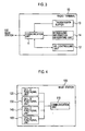
- Fig. 4 is a block diagram showing the base station 100 according to the first embodiment.
- the base station 100 includes a communication unit 110, a cell A functional unit 120, a cell B functional unit 130, a cell C functional unit 140 and a cell D functional unit 150.
- the communication unit 110 communicates with the radio terminal 10 located in the cells A to D.
- the plurality of the radio terminals 10 is located in the cells A to D, respectively.
- the communication unit 110 receives uplink user data from each of the plurality of radio terminals 10 via the data channel such as the DPDCH or the E-DPDCH.
- the communication unit 110 receives uplink control data from each of the plurality of radio terminals 10 via the control channel such as the DPCCH or the E-DPCCH.
- the communication unit 110 transmits the control data (AG or RG) to each of the plurality of radio terminals 10 via the control channel such as the E-AGCH and the E-RGCH.
- the communication unit 110 also communicates with upper apparatuses (such as a radio network controller, a switching apparatus or the like), which controls the base station 100.
- upper apparatuses such as a radio network controller, a switching apparatus or the like
- the cell A functional unit 120 functions as a serving cell for radio terminals 10 located in the cell A. Meanwhile, the cell A functional unit 120 functions as a non-serving cell for radio terminals 10 located in the cells B to D.
- the cell B functional unit 130 functions as a serving cell for radio terminals 10 located in the cell B. Meanwhile, the cell B functional unit 130 functions as a non-serving cell for radio terminals 10 located in the cells A, C and D.
- the cell C functional unit 140 functions as a serving cell for radio terminals 10 located in the cell C. Meanwhile, the cell C functional unit 140 functions as a non-serving cell for radio terminals 10 located in the cells A, B and D.
- the cell D functional unit 150 functions as a serving cell for radio terminals 10 located in the cell D. Meanwhile, the cell D functional unit 150 functions as a non-serving cell for radio terminals 10 located in the cells A to C.
- FIG. 5 is a block diagram showing the cell (the cell A functional unit 120) according to the first embodiment.
- description will be given for an example in which the cell A functional unit 120 functions as a serving cell.
- the cell A functional unit 120 includes: a scheduling unit 120a and a determination unit 125.
- the scheduling unit 120a includes an AG controlling unit 121, an RG controlling unit 122, a retransmission controlling unit 123 and a transmission slot assigning unit 124.
- the scheduling unit 120a is operated in a MAC-e (Media Access Control Enhanced) layer.
- MAC-e Media Access Control Enhanced
- the AG controlling unit 121 transmits an AG via the E-AGCH to the radio terminal 10, Note that the AG is a command for directly specifying a value of the transmission rate without relying on the current transmission rate.
- the RG controlling unit 122 transmits an RG via the E-RGCH to the radio terminal 10 (serving radio terminal of the cell A).
- the RG includes the increase command "Up” for instructing the increase of the current transmission rate, the retention command “Hold” for instructing the retention of the current transmission rate, and the decrease command "Down” for instructing the decrease of the current transmission rate.
- the increase command "Up” instructs the increase of the transmission rate by a predetermined amount
- the decrease command "Down instructs the decrease by a predetermined amount.
- the predetermined amount for the increase may be the same as or smaller than the predetermined amount for the decrease.
- the AG controlling unit 121 and the RG controlling unit 122 refers to the UL scheduling information and the like that is received from the radio terminal 10, and controls the SG to be assigned to the radio terminal 10. It is practical that a control timing of the SG (a transmission timing of the AG or the RG) is not one TTI cycle but a predetermined cycle (for example, several ten msec to several hundred msec) longer than one TTI.
- the retransmission controlling unit 123 determines, for each block (for each process), whether or not an error is occurred in the uplink user data. Thereafter, the retransmission controlling unit 123 requests the radio terminal 10 to retransmit a block in which an error is occurred (hereinafter referred to as an error block).
- a retransmission control technique is a HARQ (Hybrid Automatic Repeat Request) technique for combining a block firstly transmitted from the radio terminal 10 (hereinafter referred to as a transmission block) with a block retransmitted from the radio terminal 10 (hereinafter referred to as a retransmission block).
- the transmission slot assigning unit 124 assigns, to the radio terminal 10, a transmission slot (that is, a process included in one TTI) to be used for transmitting the uplink user data (block) via the E-DPDCH. Note that the radio terminal 10 transmits the transmission block or the retransmission block to the base station 100 by using the process (active process) assigned by the transmission slot assigning unit 124.
- the determination unit 125 determines whether the buffer information (TEBS) indicating that the uplink user data is stored in the transmission buffer of the radio terminal 10, is obtained.
- TEBS buffer information
- the scheduling unit 120a transmits, to the radio terminal 10, transmission rate control data (transmission rate decrease data) for instructing a decrease of the transmission rate (SG) assigned to the radio terminal 10, when the uplink user data is not transmitted from the radio terminal 10 by using the SG assigned to the radio terminal 10.
- transmission rate control data transmission rate decrease data
- the scheduling unit 120a transmits, to the radio terminal 10, the transmission rate decrease data for instructing the decrease of the SG.
- the AG controlling unit 121 transmits, to the radio terminal 10, an AG (Zero Grant) specifying "0" for the SG assigned to the radio terminal 10. Further, as the transmission rate decrease data, the AG controlling unit 121 may transmit, to the radio terminal 10, an AG ("Inactive") limiting the use of active processes assigned to the radio terminal 10.
- the processing of controlling the transmission rate (SG) based on the information that the uplink user data is not stored in the radio terminal 10 is basically performed independently from the processing of controlling the transmission rate (SG) by a predetermined cycle (several ten msec to several hundred msec) longer than one TTI.
- Fig. 6 is a view showing the example of the reduction in the radio resources (SG) according to the first embodiment.
- the horizontal axis indicates process numbers and the vertical axis indicates radio resources (SG) of the radio terminal 10 assigned by the base station 100.
- the base station 100 assigns the radio resources (SG) to the radio terminal 10 (UE#1) and the radio terminal 10 (UE#3).
- the base station 100 controls the radio resources (SG) assigned to the radio terminal 10 (UE#1) to the radio terminal 10 (UE#3) by transmitting transmission power control data (AG or RG) generated based on various information ("HLID”, "TEBS (buffer information)", "HLBS” and "UPH") included in the UL scheduling information. Specifically, the base station 100 newly assigns the radio resources (SG) to the radio terminal 10 (UE#2). The base station 100 reduces the radio resources (SG) assigned to the radio terminal 10 (UE#1) and to the radio terminal 10 (UE#3). Note that the radio terminal 10 (UE#3) has not used all of the assigned radio resources (SG).
- the base station 100 has received, from the radio terminal 10 (UE#3), buffer information (TEBS) indicating that the uplink user data is not stored in the radio terminal 10 (UE#3).
- TEBS buffer information
- the base station 100 transmits the AG (Zero Grant) or the AG (Inactive) to the radio terminal 10 (UE#3) and reduces the radio resources (SG) assigned to the radio terminal 10 (UE#3) to "0".
- the base station 100 transmits the transmission power control data (AG or RG) generated based on the various information included in the UL scheduling information and controls the radio resources (SG) assigned to the radio terminal 10 (UE#2).
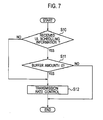
- Fig. 7 is a flowchart showing operations of the base station 100 (cell) according to the first embodiment. Note that the processings shown in Fig. 7 are repeated by a predetermined cycle (for example, one TTI).
- a predetermined cycle for example, one TTI
- the base station 100 determines whether the UL scheduling information has been received from the radio terminal 10 that uses the own of the base station 100 as the serving cell. When the UL scheduling information has been received, the base station 100 moves to a processing of Step 11. On the other hand, when the UL scheduling information has not been received, the base station 100 moves to a processing of Step 12.
- the base station 100 refers to the buffer information (TEBS) included in the UL scheduling information and determines whether the buffer amount indicated by the buffer information is "0". When the buffer amount is "0", the base station 100 moves to the processing of Step 12.
- TEBS buffer information
- the base station 100 when the buffer amount is not "0", in other words, when the uplink user data is stored in the radio terminal 10, the processing is terminated.
- the base station 100 generates the transmission power control data (AG or RG) based on the various information ("HLID”, “TEBS (buffer information)", “HLBS” and “UPH") included in the UL scheduling information, and transmits the transmission power control data (AG or RG) to the radio terminal 10, at the control timing of the SG assigned to the radio terminal 10.
- control timing of the SG (the transmission timing of the AG or the RG) is not one TTI cycle but a predetermined cycle (for example, several ten msec to several hundred msec) longer than one TTI.
- Step 12 the base station 100 transmits, to the radio terminal 10, transmission rate control data (transmission rate decrease data) for instructing the decrease of the SG assigned to the radio terminal 10.
- transmission rate control data transmission rate decrease data
- the AG controlling unit 121 transmits, to the radio terminal 10, an AG (Zero Grant) specifying "0" for the SG assigned to the radio terminal 10. Further, as the transmission rate decrease data, the AG controlling unit 121 may transmit, to the radio terminal 10, an AG ("Inactive") limiting the use of active processes assigned to the radio terminal 10.
- the base station 100 transmits, to the radio terminal 10, the transmission rate decrease data for instructing the decrease of the transmission rate (SG), when the uplink user data is not transmitted from the radio terminal 10 to the base station 100 by using the transmission rate assigned to the radio terminal 10.
- the base station 100 transmits, to the radio terminal 10, the transmission rate decrease data for instructing the decrease of the transmission rate, when the buffer information (TEBS) indicating that the uplink user data is stored in the radio terminal 10, is not obtained.
- TEBS buffer information
- the base station 100 transmits, to the radio terminal 10, the transmission rate decrease data for instructing the decrease of the transmission rate (SG).
- the transmission rate of the uplink user data can be properly controlled.
- a base station 100 transmits, to a radio terminal 10, transmission rate control data (transmission rate decrease data) for instructing a decrease of an SG, when a period for which the buffer information (TEBS) indicating that uplink user data is stored in the radio terminal 10 is not obtained, exceeds a predetermined period.
- transmission rate control data transmission rate decrease data
- FIG. 8 is a block diagram showing a cell (a cell A functional unit 120) according to the second embodiment. Note that, in Fig. 8 , the same constituent components as those shown in Fig. 5 are denoted by the same reference numerals.
- the cell A functional unit 120 includes a counter 126 in addition to the configuration shown in Fig. 5 .
- the counter 126 includes a first counter and a second counter.
- the first counter counts a period for which the UL scheduling information cannot be received from the radio terminal 10.
- the first counter is reset when the UL scheduling information is received.
- the second counter is reset when the buffer information (TEBS) indicating that the buffer amount is other than "0", i.e., the buffer information (TEBS) indicating that the uplink user data is stored in the radio terminal 10, is obtained.
- the scheduling unit 120a described above transmits, to the radio terminal 10, the transmission rate decrease data for instructing the decrease of the SG, when a value counted by the first counter exceeds a first threshold. In other words, the scheduling unit 120a transmits the transmission rate decrease data to the radio terminal 10, when the period for which the UL scheduling information cannot be received exceeds a predetermined period.
- the scheduling unit 120a described above transmits, to the radio terminal 10, the transmission rate decrease data for instructing the decrease of the SG, when a value counted by the second counter exceeds a second threshold.
- TEBS buffer information
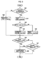
- Fig. 9 is a flowchart showing operations of the base station 100 (cell) according to the second embodiment. Note that the processing shown in Fig. 9 is repeated by a predetermined cycle (for example, one TTI).
- a predetermined cycle for example, one TTI
- Step 20 the base station 100 determines whether the UL scheduling information has been received from the radio terminal 10 that uses the cell controlled by the base station 100 as the serving cell. When the UL scheduling information has been received, the base station 100 moves to a processing of Step 21, On the other hand, when the UL scheduling information has not been received, the base station 100 moves to a processing of Step 22,
- Step 21 the base station 100 resets the first counter.
- Step 22 the base station 100 increments the first counter.
- the base station 100 refers to the buffer information included in the UL scheduling information and determines whether the buffer amount indicated by the buffer information (TEBS) is "0". When the buffer amount is "0", the base station 100 moves to the processing of Step 24. On the other hand, when the buffer amount is not "0", the base station 100 moves to a processing of Step 25.
- TEBS buffer information
- Step 24 the base station 100 increments the second counter.
- Step 25 the base station 100 resets the second counter.
- Step 26 the base station 100 determines whether or not a value counted by the first counter exceeds a first threshold. When the value counted by the first counter exceeds the first threshold, the base station 100 moves to a processing of Step 28. On the other hand, when the value counted by the first counter does not exceed the first threshold, the base station 100 moves to a processing of Step 27.
- Step 27 the base station 100 determines whether or not a value counted by the second counter exceeds a second threshold. When the value counted by the second counter exceeds the second threshold, the base station 100 moves to the processing of Step 28. On the other hand, when the value counted by the second counter does not exceed the second threshold, the base station 100 terminates the processing.
- Step 28 the base station 100 transmits, to the radio terminal 10, the transmission rate control data (transmission rate decrease data) for instructing the decrease of the SG assigned to the radio terminal 10.
- the transmission rate control data transmission rate decrease data
- considered is a case where the value counted by the first counter does not exceed the first threshold and the value counted by the second counter does not exceed the second threshold.
- the base station 100 generates the transmission power control data (AG or RG) based on the various information ("HLID”, “TEBS (buffer information)", “HLBS” and “UPH") included in the UL scheduling information, and transmits the transmission power control data (AG or RG) to the radio terminal 10, at the control timing of the SG assigned to the radio terminal 10.
- the base station 100 transmits, to the radio terminal 10, the transmission rate decrease data for instructing the decrease of the transmission rate (SG), when the period for which the buffer information (TEBS) indicating that the uplink user data is stored in the radio terminal 10 is not obtained, exceeds the predetermined period.
- the transmission rate decrease data for instructing the decrease of the transmission rate (SG)
- TEBS buffer information
- the base station 100 transmits, to the radio terminal 10, the transmission rate decrease data for instructing the decrease of the SG, when the buffer information (TEBS) indicating that the uplink user data is stored in the radio terminal 10 is not obtained.
- TEBS buffer information
- a base station 100 transmits, to a radio terminal 10, the transmission rate decrease data for instructing the decrease of the SG, when a ratio of a measured transmission rate to a predicted transmission rate (hereinafter referred to as a usage rate) is lower than a usage rate threshold.
- a usage rate a ratio of a measured transmission rate to a predicted transmission rate
- the predicted transmission rate indicates a transmission rate specified by the radio resources (SG) assigned to the radio terminal 10.
- the predicted transmission rate is recognized at the base station 100 and is notified to the base station 100 by transmitting the AG or the RG.
- the measured transmission rate indicates a transmission rate specified by an amount of the uplink user data received from the radio terminal 10.
- the cell (a cell A functional unit 120) according to the third embodiment has the same configuration as that of the first embodiment ( Fig. 5 ).
- a determination unit 125 specifies a predicted transmission rate by use of the SG assigned to the radio terminal 10.
- the SG assigned to the radio terminal 10 is recognized by the base station 100 and is notified from the base station100 by transmitting the AG or the RG. Meanwhile, the determination unit 125 specifies the measured transmission rate by an amount of the uplink user data received from the radio terminal 10.
- the determination unit 125 determines whether or not a usage rate (measured transmission rate/ predicted transmission rate) is lower than the usage rate threshold indicating the ratio of the measured transmission rate to the predicted transmission rate.
- a range of the usage rate threshold is a value "0" to "1".
- a scheduling unit 120a transmits, to the radio terminal 10, the transmission rate control data (transmission rate decrease data) for instructing the decrease of the SG assigned to the radio terminal 10, when the usage rate (measured transmission rate/ predicted transmission rate) is lower than the usage rate threshold.
- the AG controlling unit 121 transmits, to the radio terminal 10, an AG specifying the SG (predetermined value) lower than the SG assigned to the radio terminal 10.
- an RG controlling unit 122 may transmit, to the radio terminal 10, a decrease command "Down" for instructing the decrease of the SG assigned to the radio terminal 10.
- a range of the decrease of the SG assigned to the radio terminal 10 may be determined according to a difference (unused radio resources) obtained by subtracting the measured transmission rate from the predicted transmission rate.
- the decreased amount of the SG is determined to be larger when the amount of the unused radio resources is larger.
- the processing of controlling the transmission rate (SG) based on the information that the uplink user data is not stored in the radio terminal 10 is basically performed independently from the processing of controlling the transmission rate (SG) by a predetermined cycle (several ten msec to several hundred msec) longer than one TTI.
- Fig. 10 is a view showing the example of reduction in the radio resources (SG) according to the third embodiment.
- the horizontal axis indicates process numbers and the vertical axis indicates radio resources (SG) assigned to the radio terminal 10 by the base station 100.
- the base station 100 assigns the radio resources (SG) to the radio terminal 10 (UE#1) and the radio terminal 10 (UE#3).
- the base station 100 controls the radio resources (SG) assigned to the radio terminal 10 (UE#1) to the radio terminal 10 (UE#3) by transmitting transmission power control data (AG or RG) which is generated based on various information ("HLID”, "TEBS (buffer information)", “HLBS” and "UPH") included in the UL scheduling information. Specifically, the base station 100 newly assigns the radio resources (SG) to the radio terminal 10 (UE#2). The base station 100 reduces the radio resources (SG) assigned to the radio terminal 10 (UE#1) and to the radio terminal 10 (UE#3).
- transmission power control data AG or RG
- the radio terminal 10 (UE#3) has not used all of the assigned radio resources (SG). More specifically, the radio terminal 10 (UE#3) does not transmit the uplink user data by using the transmission rate corresponding to the assigned radio resources (SG).
- the base station 100 reduces the radio resources (SG) assigned to the radio terminal 10 (UE#3) by transmitting the transmission power control data (AG or RG).
- a range of the reduction in the radio resources (SG) may be determined according to a difference (unused radio resources) obtained by subtracting the measured transmission rate from the predicted transmission rate.
- FIG. 11 is a flowchart showing operations of the base station 100 (cell) according to the third embodiment.
- the base station 100 specifies the predicted transmission rate by use of the SG assigned to the radio terminal 10.
- Step 31 the base station 100 receives the uplink user data from the radio terminal 10. Subsequently, the base station 100 specifies the measured transmission rate by an amount of the uplink user data received from the radio terminal 10.
- Step 32 the base station 100 calculates the ratio of the measured transmission rate to the predicted transmission rate (hereinafter referred to as the usage rate).
- Step 33 the base station 100 determines whether or not the usage rate is lower than the usage rate threshold.
- the base station 100 moves to a processing of Step 34.
- the base station 100 terminates the processing.
- Step 34 the base station 100 transmits, to the radio terminal 10, the transmission rate control data (transmission rate decrease data) for instructing the decrease of the SG assigned to the radio terminal 10.
- the transmission rate control data transmission rate decrease data
- the AG controlling unit 121 transmits, to the radio terminal 10, an AG specifying the SG (predetermined value) lower than the SG assigned to the radio terminal 10.
- an RG controlling unit 122 may transmit, to the radio terminal 10, a decrease command "Down" for instructing the decrease of the SG assigned to the radio terminal 10.
- the base station 100 transmits, to the radio terminal 10, the transmission rate decrease data for instructing a decrease of the transmission rate, when the radio terminal 10 does not transmit the uplink user data by using the transmission rate assigned to the radio terminal 10.
- the base station 100 transmits, to the radio terminal 10, the transmission rate decrease data for instructing the decrease of the transmission rate (SG), when the usage rate (measured transmission rate/ predicted transmission rate) is lower than the usage rate threshold.
- the base station 100 transmits, to the radio terminal 10, the transmission rate decrease data for instructing the decrease of the transmission rate (SG), when the radio terminal 10 does not transmit the uplink user data by using the transmission rate assigned to the radio terminal 10.
- the transmission rate of the uplink user data can be properly controlled.
- a base station 100 transmits, to a radio terminal 10, the transmission rate control data (transmission rate decrease data) for instructing the decrease of the SG when a period for which a usage rate is lower than a usage rate threshold exceeds a predetermined period.
- the base station 100 (a counter 126 provided in a scheduling unit 120a) includes a third counter for counting a period for which the usage rate is lower than the usage rate threshold.
- Fig. 12 is a flowchart showing operations of the base station 100 (cell) according to the fourth embodiment.
- the base station 100 specifies the predicted transmission rate by use of the SG assigned to the radio terminal 10.
- Step 41 the base station 100 receives the uplink user data from the radio terminal 10. Subsequently, the base station 100 specifies the measured transmission rate by an amount of the uplink user data received from the radio terminal 10.
- Step 42 the base station 100 calculates the ratio of the measured transmission rate to the predicted transmission rate (hereinafter referred to as the usage rate).
- Step 43 the base station 100 determines whether or not the usage rate is lower than a usage rate threshold.
- the base station 100 moves to a processing of Step 44.
- the base station 100 moves to a processing of Step 45.
- Step 44 the base station 100 increments the third counter.
- Step 45 the base station 100 resets the third counter.
- the third counter counts a period for which the usage rate is lower than the usage rate threshold.
- Step 46 the base station 100 determines whether or not the value counted by the third counter exceeds a third threshold. When the value counted by the third counter exceeds the third threshold, the base station 100 moves to a processing of Step 47. On the other hand, when the value counted by the third counter does not exceed the third threshold, the base station 100 terminates the processing.
- Step 47 the base station 100 transmits, to the radio terminal 10, the transmission rate control data (transmission rate decrease data) for instructing the decrease of the SG assigned to the radio terminal 10.
- the transmission rate control data transmission rate decrease data
- the base station 100 transmits, to the radio terminal 10, the transmission rate decrease data for instructing the decrease of the transmission rate (SG), when the period for which the usage rate (measured transmission rate/ predicted transmission rate) is lower than the usage rate threshold exceeds the predetermined period.
- various counters (the first to third counters) count various periods based on increment.
- the present invention is not limited thereto.
- the various counters may count various periods based on decrement.
- the measured transmission rate may be calculated by use of the number of active processes included in a sub-frame, a target BLER, or the like.
Applications Claiming Priority (1)
| Application Number | Priority Date | Filing Date | Title |
|---|---|---|---|
| JP2007262333A JP5164512B2 (ja) | 2007-10-05 | 2007-10-05 | 無線通信システム、無線通信方法及び基地局 |
Publications (2)
| Publication Number | Publication Date |
|---|---|
| EP2045980A1 true EP2045980A1 (fr) | 2009-04-08 |
| EP2045980B1 EP2045980B1 (fr) | 2012-03-07 |
Family
ID=40289398
Family Applications (1)
| Application Number | Title | Priority Date | Filing Date |
|---|---|---|---|
| EP20080017421 Not-in-force EP2045980B1 (fr) | 2007-10-05 | 2008-10-02 | Système de communication radio, procédé de communication radio, et station de base |
Country Status (6)
| Country | Link |
|---|---|
| US (1) | US8665713B2 (fr) |
| EP (1) | EP2045980B1 (fr) |
| JP (1) | JP5164512B2 (fr) |
| KR (1) | KR101011737B1 (fr) |
| CN (1) | CN101404790B (fr) |
| AT (1) | ATE548831T1 (fr) |
Families Citing this family (5)
| Publication number | Priority date | Publication date | Assignee | Title |
|---|---|---|---|---|
| JP4776708B2 (ja) * | 2009-05-01 | 2011-09-21 | 株式会社エヌ・ティ・ティ・ドコモ | 無線基地局 |
| JP2011041229A (ja) | 2009-08-18 | 2011-02-24 | Sony Corp | 送信装置、受信装置、無線装置および送信装置における伝送モード制御方法 |
| JP5445271B2 (ja) * | 2010-03-30 | 2014-03-19 | 富士通株式会社 | 帯域制御装置,帯域制御方法,及びプログラム |
| CN112511455A (zh) * | 2020-04-30 | 2021-03-16 | 中兴通讯股份有限公司 | 信元流特征值调整方法、装置、系统和存储介质 |
| US20230038198A1 (en) * | 2021-08-03 | 2023-02-09 | At&T Intellectual Property I, L.P. | Dynamic wireless network throughput adjustment |
Citations (2)
| Publication number | Priority date | Publication date | Assignee | Title |
|---|---|---|---|---|
| EP0847220A2 (fr) | 1996-12-04 | 1998-06-10 | AT&T Corp. | Méthode d'affectation dynamique de canaux dans un réseau de télécommunication |
| EP1775982A1 (fr) | 2005-10-12 | 2007-04-18 | Samsung Electronics Co., Ltd. | Procédure et appareil pour la transmission/réception d'informations de commande de l'equipement d'un utilisateur pour la transmission de données dans le sens montant |
Family Cites Families (9)
| Publication number | Priority date | Publication date | Assignee | Title |
|---|---|---|---|---|
| US7193966B2 (en) | 2001-06-25 | 2007-03-20 | Telefonakitebolaget Lm Ericsson (Publ) | Triggered packet data rate change in a communication system |
| ATE527782T1 (de) * | 2003-03-05 | 2011-10-15 | Samsung Electronics Co Ltd | Verfahren und vorrichtung zum steuern der rückverkehrsrate in einem mobilkommunikationssystem |
| KR20040086490A (ko) * | 2003-04-02 | 2004-10-11 | 삼성전자주식회사 | 이동통신 시스템에서 패킷 데이터의 역방향 데이터 전송률제어 장치 및 방법 |
| AU2004237638B2 (en) | 2003-05-10 | 2006-11-23 | Samsung Electronics Co., Ltd. | Apparatus and method for controlling a reverse traffic rate in a mobile communication system |
| GB0501403D0 (en) * | 2005-01-22 | 2005-03-02 | Koninkl Philips Electronics Nv | Communication device, communication system and method of operating a communication device |
| US8363604B2 (en) * | 2005-02-01 | 2013-01-29 | Qualcomm Incorporated | Method and apparatus for controlling a transmission data rate based on feedback relating to channel conditions |
| JP2007028245A (ja) * | 2005-07-19 | 2007-02-01 | Fujitsu Ltd | 無線通信装置 |
| JP4534893B2 (ja) * | 2005-07-29 | 2010-09-01 | 日本電気株式会社 | 移動通信システム、無線制御局及びそれらに用いる伝送レート制御方法、伝送レート制御プログラム |
| WO2007043455A1 (fr) * | 2005-10-07 | 2007-04-19 | Nec Corporation | Procédé de transmission de signal, système de communication radio, station de communication, station mobile et station de base |
-
2007
- 2007-10-05 JP JP2007262333A patent/JP5164512B2/ja not_active Expired - Fee Related
-
2008
- 2008-10-02 AT AT08017421T patent/ATE548831T1/de active
- 2008-10-02 EP EP20080017421 patent/EP2045980B1/fr not_active Not-in-force
- 2008-10-02 US US12/244,034 patent/US8665713B2/en active Active
- 2008-10-02 KR KR20080097048A patent/KR101011737B1/ko not_active IP Right Cessation
- 2008-10-06 CN CN2008101689730A patent/CN101404790B/zh not_active Expired - Fee Related
Patent Citations (2)
| Publication number | Priority date | Publication date | Assignee | Title |
|---|---|---|---|---|
| EP0847220A2 (fr) | 1996-12-04 | 1998-06-10 | AT&T Corp. | Méthode d'affectation dynamique de canaux dans un réseau de télécommunication |
| EP1775982A1 (fr) | 2005-10-12 | 2007-04-18 | Samsung Electronics Co., Ltd. | Procédure et appareil pour la transmission/réception d'informations de commande de l'equipement d'un utilisateur pour la transmission de données dans le sens montant |
Non-Patent Citations (4)
| Title |
|---|
| "Rate-request proposal", 3GPP DRAFT; R2-050179 RATE-REQUEST DISCUSSION DOCUMENT V7, 3RD GENERATION PARTNERSHIP PROJECT (3GPP), MOBILE COMPETENCE CENTRE ; 650, ROUTE DES LUCIOLES ; F-06921 SOPHIA-ANTIPOLIS CEDEX ; FRANCE, vol. tsg_ran\WG2_RL2\TSGR2_45bis\Docs, no. Sophia Antipolis, France; 20050110, 6 January 2005 (2005-01-06), XP050127456 * |
| "Universal Mobile Telecommunications System (UMTS); Enhanced uplink; Overall description; Stage 2 (3GPP TS 25.319 version 7.2.0 Release 7); ETSI TS 125 319", ETSI STANDARDS, LIS, SOPHIA ANTIPOLIS CEDEX, FRANCE, vol. 3-R2, no. V7.2.0, 1 March 2007 (2007-03-01), XP014037911, ISSN: 0000-0001 * |
| 3GPP TSG-RAN WG2, 10 January 2005 (2005-01-10) |
| ETSI TS 125 319, March 2007 (2007-03-01) |
Also Published As
| Publication number | Publication date |
|---|---|
| ATE548831T1 (de) | 2012-03-15 |
| KR20090035444A (ko) | 2009-04-09 |
| US20090092104A1 (en) | 2009-04-09 |
| EP2045980B1 (fr) | 2012-03-07 |
| CN101404790A (zh) | 2009-04-08 |
| KR101011737B1 (ko) | 2011-02-07 |
| CN101404790B (zh) | 2011-12-21 |
| US8665713B2 (en) | 2014-03-04 |
| JP2009094717A (ja) | 2009-04-30 |
| JP5164512B2 (ja) | 2013-03-21 |
Similar Documents
| Publication | Publication Date | Title |
|---|---|---|
| EP2053896B1 (fr) | Système de communication radio, procédé de communication radio, station de base radio et terminal radio | |
| US7801550B2 (en) | Radio communication system and method where a radio terminal transmits uplink user data to a base station through an enhanced deticated physical data channel | |
| US8665713B2 (en) | Radio communication system, radio communication method and base station | |
| EP2048905B1 (fr) | Contrôle de débit de transmission d'une liaison montante dans un système de communication radio | |
| EP2317817B1 (fr) | Station de base, noeud supérieur, système de communication radio et procédé de communication radio | |
| US8249633B2 (en) | Radio communication system, radio communication method and base station | |
| US8340019B2 (en) | Radio communication system, radio communication method, and base station for controlling a transmission rate of uplink user data | |
| US8432795B2 (en) | Radio communication system, radio communication method and base station | |
| EP2045979B1 (fr) | Système de communication radio, procédé de communication radio, et station de base |
Legal Events
| Date | Code | Title | Description |
|---|---|---|---|
| PUAI | Public reference made under article 153(3) epc to a published international application that has entered the european phase |
Free format text: ORIGINAL CODE: 0009012 |
|
| 17P | Request for examination filed |
Effective date: 20081002 |
|
| AK | Designated contracting states |
Kind code of ref document: A1 Designated state(s): AT BE BG CH CY CZ DE DK EE ES FI FR GB GR HR HU IE IS IT LI LT LU LV MC MT NL NO PL PT RO SE SI SK TR |
|
| AX | Request for extension of the european patent |
Extension state: AL BA MK RS |
|
| 17Q | First examination report despatched |
Effective date: 20090722 |
|
| AKX | Designation fees paid |
Designated state(s): AT BE BG CH CY CZ DE DK EE ES FI FR GB GR HR HU IE IS IT LI LT LU LV MC MT NL NO PL PT RO SE SI SK TR |
|
| GRAJ | Information related to disapproval of communication of intention to grant by the applicant or resumption of examination proceedings by the epo deleted |
Free format text: ORIGINAL CODE: EPIDOSDIGR1 |
|
| GRAP | Despatch of communication of intention to grant a patent |
Free format text: ORIGINAL CODE: EPIDOSNIGR1 |
|
| GRAP | Despatch of communication of intention to grant a patent |
Free format text: ORIGINAL CODE: EPIDOSNIGR1 |
|
| RAP1 | Party data changed (applicant data changed or rights of an application transferred) |
Owner name: NTT DOCOMO, INC. |
|
| GRAS | Grant fee paid |
Free format text: ORIGINAL CODE: EPIDOSNIGR3 |
|
| GRAA | (expected) grant |
Free format text: ORIGINAL CODE: 0009210 |
|
| RAP1 | Party data changed (applicant data changed or rights of an application transferred) |
Owner name: NTT DOCOMO, INC. |
|
| AK | Designated contracting states |
Kind code of ref document: B1 Designated state(s): AT BE BG CH CY CZ DE DK EE ES FI FR GB GR HR HU IE IS IT LI LT LU LV MC MT NL NO PL PT RO SE SI SK TR |
|
| RAP1 | Party data changed (applicant data changed or rights of an application transferred) |
Owner name: NTT DOCOMO, INC. |
|
| REG | Reference to a national code |
Ref country code: GB Ref legal event code: FG4D |
|
| REG | Reference to a national code |
Ref country code: AT Ref legal event code: REF Ref document number: 548831 Country of ref document: AT Kind code of ref document: T Effective date: 20120315 Ref country code: CH Ref legal event code: EP |
|
| REG | Reference to a national code |
Ref country code: IE Ref legal event code: FG4D |
|
| REG | Reference to a national code |
Ref country code: DE Ref legal event code: R096 Ref document number: 602008013862 Country of ref document: DE Effective date: 20120426 |
|
| REG | Reference to a national code |
Ref country code: NL Ref legal event code: VDEP Effective date: 20120307 |
|
| PG25 | Lapsed in a contracting state [announced via postgrant information from national office to epo] |
Ref country code: HR Free format text: LAPSE BECAUSE OF FAILURE TO SUBMIT A TRANSLATION OF THE DESCRIPTION OR TO PAY THE FEE WITHIN THE PRESCRIBED TIME-LIMIT Effective date: 20120307 Ref country code: NL Free format text: LAPSE BECAUSE OF FAILURE TO SUBMIT A TRANSLATION OF THE DESCRIPTION OR TO PAY THE FEE WITHIN THE PRESCRIBED TIME-LIMIT Effective date: 20120307 Ref country code: NO Free format text: LAPSE BECAUSE OF FAILURE TO SUBMIT A TRANSLATION OF THE DESCRIPTION OR TO PAY THE FEE WITHIN THE PRESCRIBED TIME-LIMIT Effective date: 20120607 Ref country code: LT Free format text: LAPSE BECAUSE OF FAILURE TO SUBMIT A TRANSLATION OF THE DESCRIPTION OR TO PAY THE FEE WITHIN THE PRESCRIBED TIME-LIMIT Effective date: 20120307 |
|
| LTIE | Lt: invalidation of european patent or patent extension |
Effective date: 20120307 |
|
| PG25 | Lapsed in a contracting state [announced via postgrant information from national office to epo] |
Ref country code: FI Free format text: LAPSE BECAUSE OF FAILURE TO SUBMIT A TRANSLATION OF THE DESCRIPTION OR TO PAY THE FEE WITHIN THE PRESCRIBED TIME-LIMIT Effective date: 20120307 Ref country code: LV Free format text: LAPSE BECAUSE OF FAILURE TO SUBMIT A TRANSLATION OF THE DESCRIPTION OR TO PAY THE FEE WITHIN THE PRESCRIBED TIME-LIMIT Effective date: 20120307 Ref country code: GR Free format text: LAPSE BECAUSE OF FAILURE TO SUBMIT A TRANSLATION OF THE DESCRIPTION OR TO PAY THE FEE WITHIN THE PRESCRIBED TIME-LIMIT Effective date: 20120608 |
|
| REG | Reference to a national code |
Ref country code: AT Ref legal event code: MK05 Ref document number: 548831 Country of ref document: AT Kind code of ref document: T Effective date: 20120307 |
|
| PG25 | Lapsed in a contracting state [announced via postgrant information from national office to epo] |
Ref country code: CY Free format text: LAPSE BECAUSE OF FAILURE TO SUBMIT A TRANSLATION OF THE DESCRIPTION OR TO PAY THE FEE WITHIN THE PRESCRIBED TIME-LIMIT Effective date: 20120307 |
|
| PG25 | Lapsed in a contracting state [announced via postgrant information from national office to epo] |
Ref country code: RO Free format text: LAPSE BECAUSE OF FAILURE TO SUBMIT A TRANSLATION OF THE DESCRIPTION OR TO PAY THE FEE WITHIN THE PRESCRIBED TIME-LIMIT Effective date: 20120307 Ref country code: PL Free format text: LAPSE BECAUSE OF FAILURE TO SUBMIT A TRANSLATION OF THE DESCRIPTION OR TO PAY THE FEE WITHIN THE PRESCRIBED TIME-LIMIT Effective date: 20120307 Ref country code: SI Free format text: LAPSE BECAUSE OF FAILURE TO SUBMIT A TRANSLATION OF THE DESCRIPTION OR TO PAY THE FEE WITHIN THE PRESCRIBED TIME-LIMIT Effective date: 20120307 Ref country code: CZ Free format text: LAPSE BECAUSE OF FAILURE TO SUBMIT A TRANSLATION OF THE DESCRIPTION OR TO PAY THE FEE WITHIN THE PRESCRIBED TIME-LIMIT Effective date: 20120307 Ref country code: EE Free format text: LAPSE BECAUSE OF FAILURE TO SUBMIT A TRANSLATION OF THE DESCRIPTION OR TO PAY THE FEE WITHIN THE PRESCRIBED TIME-LIMIT Effective date: 20120307 Ref country code: SE Free format text: LAPSE BECAUSE OF FAILURE TO SUBMIT A TRANSLATION OF THE DESCRIPTION OR TO PAY THE FEE WITHIN THE PRESCRIBED TIME-LIMIT Effective date: 20120307 Ref country code: IS Free format text: LAPSE BECAUSE OF FAILURE TO SUBMIT A TRANSLATION OF THE DESCRIPTION OR TO PAY THE FEE WITHIN THE PRESCRIBED TIME-LIMIT Effective date: 20120707 Ref country code: BE Free format text: LAPSE BECAUSE OF FAILURE TO SUBMIT A TRANSLATION OF THE DESCRIPTION OR TO PAY THE FEE WITHIN THE PRESCRIBED TIME-LIMIT Effective date: 20120307 |
|
| PG25 | Lapsed in a contracting state [announced via postgrant information from national office to epo] |
Ref country code: SK Free format text: LAPSE BECAUSE OF FAILURE TO SUBMIT A TRANSLATION OF THE DESCRIPTION OR TO PAY THE FEE WITHIN THE PRESCRIBED TIME-LIMIT Effective date: 20120307 Ref country code: PT Free format text: LAPSE BECAUSE OF FAILURE TO SUBMIT A TRANSLATION OF THE DESCRIPTION OR TO PAY THE FEE WITHIN THE PRESCRIBED TIME-LIMIT Effective date: 20120709 |
|
| PLBE | No opposition filed within time limit |
Free format text: ORIGINAL CODE: 0009261 |
|
| STAA | Information on the status of an ep patent application or granted ep patent |
Free format text: STATUS: NO OPPOSITION FILED WITHIN TIME LIMIT |
|
| PG25 | Lapsed in a contracting state [announced via postgrant information from national office to epo] |
Ref country code: DK Free format text: LAPSE BECAUSE OF FAILURE TO SUBMIT A TRANSLATION OF THE DESCRIPTION OR TO PAY THE FEE WITHIN THE PRESCRIBED TIME-LIMIT Effective date: 20120307 Ref country code: AT Free format text: LAPSE BECAUSE OF FAILURE TO SUBMIT A TRANSLATION OF THE DESCRIPTION OR TO PAY THE FEE WITHIN THE PRESCRIBED TIME-LIMIT Effective date: 20120307 |
|
| 26N | No opposition filed |
Effective date: 20121210 |
|
| PG25 | Lapsed in a contracting state [announced via postgrant information from national office to epo] |
Ref country code: IT Free format text: LAPSE BECAUSE OF FAILURE TO SUBMIT A TRANSLATION OF THE DESCRIPTION OR TO PAY THE FEE WITHIN THE PRESCRIBED TIME-LIMIT Effective date: 20120307 |
|
| PGFP | Annual fee paid to national office [announced via postgrant information from national office to epo] |
Ref country code: GB Payment date: 20121105 Year of fee payment: 5 |
|
| REG | Reference to a national code |
Ref country code: DE Ref legal event code: R097 Ref document number: 602008013862 Country of ref document: DE Effective date: 20121210 |
|
| PG25 | Lapsed in a contracting state [announced via postgrant information from national office to epo] |
Ref country code: ES Free format text: LAPSE BECAUSE OF FAILURE TO SUBMIT A TRANSLATION OF THE DESCRIPTION OR TO PAY THE FEE WITHIN THE PRESCRIBED TIME-LIMIT Effective date: 20120618 |
|
| PG25 | Lapsed in a contracting state [announced via postgrant information from national office to epo] |
Ref country code: MC Free format text: LAPSE BECAUSE OF NON-PAYMENT OF DUE FEES Effective date: 20121031 |
|
| REG | Reference to a national code |
Ref country code: CH Ref legal event code: PL |
|
| REG | Reference to a national code |
Ref country code: IE Ref legal event code: MM4A |
|
| REG | Reference to a national code |
Ref country code: FR Ref legal event code: ST Effective date: 20130628 |
|
| PG25 | Lapsed in a contracting state [announced via postgrant information from national office to epo] |
Ref country code: CH Free format text: LAPSE BECAUSE OF NON-PAYMENT OF DUE FEES Effective date: 20121031 Ref country code: IE Free format text: LAPSE BECAUSE OF NON-PAYMENT OF DUE FEES Effective date: 20121002 Ref country code: LI Free format text: LAPSE BECAUSE OF NON-PAYMENT OF DUE FEES Effective date: 20121031 Ref country code: BG Free format text: LAPSE BECAUSE OF FAILURE TO SUBMIT A TRANSLATION OF THE DESCRIPTION OR TO PAY THE FEE WITHIN THE PRESCRIBED TIME-LIMIT Effective date: 20120607 |
|
| PG25 | Lapsed in a contracting state [announced via postgrant information from national office to epo] |
Ref country code: FR Free format text: LAPSE BECAUSE OF NON-PAYMENT OF DUE FEES Effective date: 20121031 |
|
| PG25 | Lapsed in a contracting state [announced via postgrant information from national office to epo] |
Ref country code: MT Free format text: LAPSE BECAUSE OF FAILURE TO SUBMIT A TRANSLATION OF THE DESCRIPTION OR TO PAY THE FEE WITHIN THE PRESCRIBED TIME-LIMIT Effective date: 20120307 |
|
| PG25 | Lapsed in a contracting state [announced via postgrant information from national office to epo] |
Ref country code: TR Free format text: LAPSE BECAUSE OF FAILURE TO SUBMIT A TRANSLATION OF THE DESCRIPTION OR TO PAY THE FEE WITHIN THE PRESCRIBED TIME-LIMIT Effective date: 20120307 |
|
| PG25 | Lapsed in a contracting state [announced via postgrant information from national office to epo] |
Ref country code: LU Free format text: LAPSE BECAUSE OF NON-PAYMENT OF DUE FEES Effective date: 20121002 |
|
| GBPC | Gb: european patent ceased through non-payment of renewal fee |
Effective date: 20131002 |
|
| PG25 | Lapsed in a contracting state [announced via postgrant information from national office to epo] |
Ref country code: HU Free format text: LAPSE BECAUSE OF FAILURE TO SUBMIT A TRANSLATION OF THE DESCRIPTION OR TO PAY THE FEE WITHIN THE PRESCRIBED TIME-LIMIT Effective date: 20081002 Ref country code: GB Free format text: LAPSE BECAUSE OF NON-PAYMENT OF DUE FEES Effective date: 20131002 |
|
| PGFP | Annual fee paid to national office [announced via postgrant information from national office to epo] |
Ref country code: DE Payment date: 20180918 Year of fee payment: 11 |
|
| REG | Reference to a national code |
Ref country code: DE Ref legal event code: R119 Ref document number: 602008013862 Country of ref document: DE |
|
| PG25 | Lapsed in a contracting state [announced via postgrant information from national office to epo] |
Ref country code: DE Free format text: LAPSE BECAUSE OF NON-PAYMENT OF DUE FEES Effective date: 20200501 |