EP2048481A1 - Liquid dispensing system with enhanced mixing - Google Patents
Liquid dispensing system with enhanced mixing Download PDFInfo
- Publication number
- EP2048481A1 EP2048481A1 EP09151128A EP09151128A EP2048481A1 EP 2048481 A1 EP2048481 A1 EP 2048481A1 EP 09151128 A EP09151128 A EP 09151128A EP 09151128 A EP09151128 A EP 09151128A EP 2048481 A1 EP2048481 A1 EP 2048481A1
- Authority
- EP
- European Patent Office
- Prior art keywords
- fluid
- reservoir
- pump
- amount
- dispensing apparatus
- Prior art date
- Legal status (The legal status is an assumption and is not a legal conclusion. Google has not performed a legal analysis and makes no representation as to the accuracy of the status listed.)
- Granted
Links
- 239000007788 liquid Substances 0.000 title description 10
- 239000012530 fluid Substances 0.000 claims abstract description 154
- 238000004891 communication Methods 0.000 claims abstract description 20
- 238000000034 method Methods 0.000 claims abstract description 18
- 230000001105 regulatory effect Effects 0.000 claims abstract description 14
- 238000000926 separation method Methods 0.000 claims abstract description 6
- 239000000839 emulsion Substances 0.000 claims description 15
- 239000000725 suspension Substances 0.000 claims description 15
- 238000005086 pumping Methods 0.000 claims description 12
- 230000002572 peristaltic effect Effects 0.000 description 8
- 238000010586 diagram Methods 0.000 description 5
- 239000000945 filler Substances 0.000 description 4
- 238000004140 cleaning Methods 0.000 description 3
- 238000006073 displacement reaction Methods 0.000 description 3
- -1 polyethylene Polymers 0.000 description 3
- 239000007787 solid Substances 0.000 description 3
- 239000004698 Polyethylene Substances 0.000 description 2
- 238000011109 contamination Methods 0.000 description 2
- 230000036512 infertility Effects 0.000 description 2
- 238000009434 installation Methods 0.000 description 2
- 239000000463 material Substances 0.000 description 2
- 229920000573 polyethylene Polymers 0.000 description 2
- 239000004743 Polypropylene Substances 0.000 description 1
- 238000013019 agitation Methods 0.000 description 1
- 230000001276 controlling effect Effects 0.000 description 1
- 229940126534 drug product Drugs 0.000 description 1
- 229920001971 elastomer Polymers 0.000 description 1
- 239000000806 elastomer Substances 0.000 description 1
- 230000003028 elevating effect Effects 0.000 description 1
- 230000005484 gravity Effects 0.000 description 1
- 239000000203 mixture Substances 0.000 description 1
- 230000003287 optical effect Effects 0.000 description 1
- 230000000737 periodic effect Effects 0.000 description 1
- 239000000825 pharmaceutical preparation Substances 0.000 description 1
- 238000005191 phase separation Methods 0.000 description 1
- 239000004033 plastic Substances 0.000 description 1
- 229920003023 plastic Polymers 0.000 description 1
- 229920000642 polymer Polymers 0.000 description 1
- 229920001155 polypropylene Polymers 0.000 description 1
- 229920001296 polysiloxane Polymers 0.000 description 1
- 230000001954 sterilising effect Effects 0.000 description 1
- 238000004659 sterilization and disinfection Methods 0.000 description 1
- 150000003431 steroids Chemical class 0.000 description 1
- 239000000126 substance Substances 0.000 description 1
- 238000011144 upstream manufacturing Methods 0.000 description 1
- 229960005486 vaccine Drugs 0.000 description 1
Images


Classifications
-
- G—PHYSICS
- G01—MEASURING; TESTING
- G01F—MEASURING VOLUME, VOLUME FLOW, MASS FLOW OR LIQUID LEVEL; METERING BY VOLUME
- G01F11/00—Apparatus requiring external operation adapted at each repeated and identical operation to measure and separate a predetermined volume of fluid or fluent solid material from a supply or container, without regard to weight, and to deliver it
- G01F11/10—Apparatus requiring external operation adapted at each repeated and identical operation to measure and separate a predetermined volume of fluid or fluent solid material from a supply or container, without regard to weight, and to deliver it with measuring chambers moved during operation
- G01F11/12—Apparatus requiring external operation adapted at each repeated and identical operation to measure and separate a predetermined volume of fluid or fluent solid material from a supply or container, without regard to weight, and to deliver it with measuring chambers moved during operation of the valve type, i.e. the separating being effected by fluid-tight or powder-tight movements
- G01F11/125—Apparatus requiring external operation adapted at each repeated and identical operation to measure and separate a predetermined volume of fluid or fluent solid material from a supply or container, without regard to weight, and to deliver it with measuring chambers moved during operation of the valve type, i.e. the separating being effected by fluid-tight or powder-tight movements of the peristaltic pump type
-
- B—PERFORMING OPERATIONS; TRANSPORTING
- B01—PHYSICAL OR CHEMICAL PROCESSES OR APPARATUS IN GENERAL
- B01F—MIXING, e.g. DISSOLVING, EMULSIFYING OR DISPERSING
- B01F23/00—Mixing according to the phases to be mixed, e.g. dispersing or emulsifying
- B01F23/02—Maintaining the aggregation state of the mixed materials
- B01F23/023—Preventing sedimentation, conglomeration or agglomeration of solid ingredients during or after mixing by maintaining mixed ingredients in movement
-
- B—PERFORMING OPERATIONS; TRANSPORTING
- B01—PHYSICAL OR CHEMICAL PROCESSES OR APPARATUS IN GENERAL
- B01F—MIXING, e.g. DISSOLVING, EMULSIFYING OR DISPERSING
- B01F25/00—Flow mixers; Mixers for falling materials, e.g. solid particles
- B01F25/50—Circulation mixers, e.g. wherein at least part of the mixture is discharged from and reintroduced into a receptacle
- B01F25/51—Circulation mixers, e.g. wherein at least part of the mixture is discharged from and reintroduced into a receptacle in which the mixture is circulated through a set of tubes, e.g. with gradual introduction of a component into the circulating flow
-
- B—PERFORMING OPERATIONS; TRANSPORTING
- B01—PHYSICAL OR CHEMICAL PROCESSES OR APPARATUS IN GENERAL
- B01F—MIXING, e.g. DISSOLVING, EMULSIFYING OR DISPERSING
- B01F25/00—Flow mixers; Mixers for falling materials, e.g. solid particles
- B01F25/50—Circulation mixers, e.g. wherein at least part of the mixture is discharged from and reintroduced into a receptacle
- B01F25/52—Circulation mixers, e.g. wherein at least part of the mixture is discharged from and reintroduced into a receptacle with a rotary stirrer in the recirculation tube
-
- B—PERFORMING OPERATIONS; TRANSPORTING
- B01—PHYSICAL OR CHEMICAL PROCESSES OR APPARATUS IN GENERAL
- B01F—MIXING, e.g. DISSOLVING, EMULSIFYING OR DISPERSING
- B01F31/00—Mixers with shaking, oscillating, or vibrating mechanisms
- B01F31/65—Mixers with shaking, oscillating, or vibrating mechanisms the materials to be mixed being directly submitted to a pulsating movement, e.g. by means of an oscillating piston or air column
- B01F31/651—Mixing by successively aspirating a part of the mixture in a conduit, e.g. a piston, and reinjecting it through the same conduit into the receptacle
-
- B—PERFORMING OPERATIONS; TRANSPORTING
- B01—PHYSICAL OR CHEMICAL PROCESSES OR APPARATUS IN GENERAL
- B01F—MIXING, e.g. DISSOLVING, EMULSIFYING OR DISPERSING
- B01F35/00—Accessories for mixers; Auxiliary operations or auxiliary devices; Parts or details of general application
- B01F35/20—Measuring; Control or regulation
- B01F35/21—Measuring
- B01F35/211—Measuring of the operational parameters
- B01F35/2112—Level of material in a container or the position or shape of the upper surface of the material
-
- B—PERFORMING OPERATIONS; TRANSPORTING
- B01—PHYSICAL OR CHEMICAL PROCESSES OR APPARATUS IN GENERAL
- B01F—MIXING, e.g. DISSOLVING, EMULSIFYING OR DISPERSING
- B01F35/00—Accessories for mixers; Auxiliary operations or auxiliary devices; Parts or details of general application
- B01F35/50—Mixing receptacles
- B01F35/53—Mixing receptacles characterised by the configuration of the interior, e.g. baffles for facilitating the mixing of components
- B01F35/531—Mixing receptacles characterised by the configuration of the interior, e.g. baffles for facilitating the mixing of components with baffles, plates or bars on the wall or the bottom
-
- B—PERFORMING OPERATIONS; TRANSPORTING
- B01—PHYSICAL OR CHEMICAL PROCESSES OR APPARATUS IN GENERAL
- B01F—MIXING, e.g. DISSOLVING, EMULSIFYING OR DISPERSING
- B01F35/00—Accessories for mixers; Auxiliary operations or auxiliary devices; Parts or details of general application
- B01F35/71—Feed mechanisms
- B01F35/712—Feed mechanisms for feeding fluids
-
- B—PERFORMING OPERATIONS; TRANSPORTING
- B01—PHYSICAL OR CHEMICAL PROCESSES OR APPARATUS IN GENERAL
- B01F—MIXING, e.g. DISSOLVING, EMULSIFYING OR DISPERSING
- B01F35/00—Accessories for mixers; Auxiliary operations or auxiliary devices; Parts or details of general application
- B01F35/71—Feed mechanisms
- B01F35/714—Feed mechanisms for feeding predetermined amounts
-
- B—PERFORMING OPERATIONS; TRANSPORTING
- B01—PHYSICAL OR CHEMICAL PROCESSES OR APPARATUS IN GENERAL
- B01F—MIXING, e.g. DISSOLVING, EMULSIFYING OR DISPERSING
- B01F35/00—Accessories for mixers; Auxiliary operations or auxiliary devices; Parts or details of general application
- B01F35/71—Feed mechanisms
- B01F35/717—Feed mechanisms characterised by the means for feeding the components to the mixer
- B01F35/7176—Feed mechanisms characterised by the means for feeding the components to the mixer using pumps
- B01F35/717611—Peristaltic pumps
-
- B—PERFORMING OPERATIONS; TRANSPORTING
- B01—PHYSICAL OR CHEMICAL PROCESSES OR APPARATUS IN GENERAL
- B01F—MIXING, e.g. DISSOLVING, EMULSIFYING OR DISPERSING
- B01F35/00—Accessories for mixers; Auxiliary operations or auxiliary devices; Parts or details of general application
- B01F35/71—Feed mechanisms
- B01F35/717—Feed mechanisms characterised by the means for feeding the components to the mixer
- B01F35/71805—Feed mechanisms characterised by the means for feeding the components to the mixer using valves, gates, orifices or openings
-
- B—PERFORMING OPERATIONS; TRANSPORTING
- B01—PHYSICAL OR CHEMICAL PROCESSES OR APPARATUS IN GENERAL
- B01F—MIXING, e.g. DISSOLVING, EMULSIFYING OR DISPERSING
- B01F35/00—Accessories for mixers; Auxiliary operations or auxiliary devices; Parts or details of general application
- B01F35/75—Discharge mechanisms
- B01F35/754—Discharge mechanisms characterised by the means for discharging the components from the mixer
- B01F35/7544—Discharge mechanisms characterised by the means for discharging the components from the mixer using pumps
-
- B—PERFORMING OPERATIONS; TRANSPORTING
- B01—PHYSICAL OR CHEMICAL PROCESSES OR APPARATUS IN GENERAL
- B01F—MIXING, e.g. DISSOLVING, EMULSIFYING OR DISPERSING
- B01F35/00—Accessories for mixers; Auxiliary operations or auxiliary devices; Parts or details of general application
- B01F35/75—Discharge mechanisms
- B01F35/754—Discharge mechanisms characterised by the means for discharging the components from the mixer
- B01F35/7547—Discharge mechanisms characterised by the means for discharging the components from the mixer using valves, gates, orifices or openings
-
- B—PERFORMING OPERATIONS; TRANSPORTING
- B01—PHYSICAL OR CHEMICAL PROCESSES OR APPARATUS IN GENERAL
- B01F—MIXING, e.g. DISSOLVING, EMULSIFYING OR DISPERSING
- B01F2101/00—Mixing characterised by the nature of the mixed materials or by the application field
- B01F2101/22—Mixing of ingredients for pharmaceutical or medical compositions
-
- B—PERFORMING OPERATIONS; TRANSPORTING
- B01—PHYSICAL OR CHEMICAL PROCESSES OR APPARATUS IN GENERAL
- B01F—MIXING, e.g. DISSOLVING, EMULSIFYING OR DISPERSING
- B01F23/00—Mixing according to the phases to be mixed, e.g. dispersing or emulsifying
- B01F23/02—Maintaining the aggregation state of the mixed materials
- B01F23/024—Maintaining mixed ingredients in movement to prevent separation of the ingredients after mixing
-
- B—PERFORMING OPERATIONS; TRANSPORTING
- B01—PHYSICAL OR CHEMICAL PROCESSES OR APPARATUS IN GENERAL
- B01F—MIXING, e.g. DISSOLVING, EMULSIFYING OR DISPERSING
- B01F35/00—Accessories for mixers; Auxiliary operations or auxiliary devices; Parts or details of general application
- B01F35/20—Measuring; Control or regulation
Definitions
- positive displacement fillers There are various types of dispensing apparatuses for filling parenteral and opthalmic products into vials and containers.
- One such type is positive displacement fillers. These devices employ a cylinder and piston arrangement, which contacts and dispenses the fluid. Typically, fluid enters the cylinder as the piston is in its upward motion, which creates a vacuum into which the fluid enters through an inlet port. The downward motion of the piston expels the fluid through an outlet port. The process can then be repeated.
- Other embodiments of positive displacement fillers also exist, such as those using rotary pumps.
- time/pressure filler Another type of dispensing, apparatus is the time/pressure filler. These typically include a fluid chamber that is held under constant pressure. Fluid is dispensed through a discharge line, which is controlled by a pinch type valve. The valve is opened for a precise amount of time to dispense fluid. Since.the pressure is held constant, and the time interval is constant, the amount of fluid dispensed should also be constant. However, due to variances in the equipment and deformation of the discharge tube over time, these systems are less accurate than required for many applications.
- a third type of dispensing apparatus is the volumetric dispensing apparatus, as shown in U.S. Patents 5,680,960 , 5,480,063 , and Publication No. 2005-0029301 , which are hereby incorporated by reference. These devices measure and dispense a predetermined volume of fluid. These systems are highly accurate and avoid problems of contamination common with positive displacement apparatus, since there are no moving parts in contact with the fluid.
- the above mentioned apparatus can all be used to dispense single-phase fluids but all of the apparatus described suffer from one or more significant drawbacks when dispensing solids dispersed in liquid (suspensions) or droplets of one liquid suspended in another liquid (emulsions).
- Suspension products such as vaccines or steroid products may settle when not properly agitated.
- the two liquids will form droplets when they are agitated but when agitation stops, the droplets may separate into two separate layers. Either of these cases will result in poor content uniformity from one vial to the next during the final dispensing of the product.
- the problems of the prior art have been overcome by the present invention, which provides a novel dispense cartridge suitable for installation into a host apparatus for dispensing suspensions or emulsions.
- the fluid dispense cartridge is particularly well suited to be manufactured in a single-use format comprising a fluid reservoir and fill tube assembly, particularly comprising a reservoir, tubing, fittings and connectors, and a needle.
- the system ensures uniformity within the liquid by moving the fluid through the product reservoir such as with a continuous or pulsating flow.
- peristaltic pumps or other non-invasive pumping apparatus, are positioned upstream and downstream of the fluid reservoir, in fluid communication with and forming a single loop with a well-mixed fluid source. Circulation between the fluid source and the reservoir is maintained so as to ensure a constant liquid level in the reservoir.
- a peristaltic pump or other non-invasive pumping apparatus, circulates fluid through the reservoir.
- a well-mixed fluid source feeds liquid to the recirculation line via a second pump or pinch valve to maintain a proper fluid level in the reservoir.
- a reversing pump is placed between the reservoir and fluid source to periodically or continuously pump fluid into and out of the reservoir.
- the single-use format allows for easy installation, pre-sterilization, and easy clean-up which will result in minimal downtime, significant cleaning chemical cost reduction, and greater ensured sterility.
- the shape and material of the reservoir are critical in maintaining product uniformity.
- the dispense system described here consists of a single-use dispense cartridge and a hardware component onto which the dispense cartridge can be installed.
- the hardware system is described in the prior art ( U.S. Patents 5,680,960 and 5,480,063 , the disclosures incorporated herein by reference).
- the present invention provides for a novel dispense cartridge and method that allows for the accurate dispensing of suspensions or emulsions.
- the fluid reservoir section of the dispense cartridge is a pliable or flexible chamber or bladder, which expands and contracts to maintain a constant internal pressure.
- Disposable bag-like enclosures are particularly suitable.
- the tubing section of the dispense cartridge consists of flexible tubing such as silicone, polyethylene, or other elastomer or polymer based tubing attached together with plastic connectors made of materials such as polyethylene, polypropylene, or poly-fluorocarbons.
- Figure 1 shows one embodiment of the dispense cartridge.
- An inlet (21) and outlet (22) port on the reservoir (20) are connected with a tubing loop (15).
- a port (25) on the bottom of the reservoir (20) is provided to allow liquid to move to the tubing assembly used to deliver the product to its final containers (not shown).
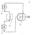
- FIG. 2 shows a single-loop dispensing system in accordance with one embodiment of the present invention.
- the system includes a feed pump (1) in fluid communication with a well mixed, bulk fluid supply source (4) and with the inlet or fill port of a fluid reservoir of the dispense cartridge (3), and a draw pump (2) in fluid communication with an outlet of reservoir of the dispense cartridge (3) and the feed to the well mixed bulk fluid supply source (4).
- Configuring the feed pump (1) and draw pump (2) in this way isolates the dispense cartridge (3) from the weight or pressure of the fluid column in the re-circulation line.
- Any type of non-invasive pumping apparatus can be used, but peristaltic pumps are particularly advantageous for pharmaceutical applications, because the fluid does not contact any components of the pump and seals and valves are not necessary.
- a level sensor (part of the hardware system - not shown) such as an optical sensor or capacitance sensor can be used to monitor the fluid level in the reservoir of the dispense cartridge (3), and the pump speeds may be controlled thereby to maintain a consistent fluid level.
- a level switch can be used, in which case the pumps may be controlled in an on/off fashion. For example, one pump may be on continuously but slower than the other pump, which is on intermittently. Regardless of the relative operation of the pumps, it is important that neither pump be off for a time sufficient to allow enough of the solids in the suspension or emulsion to separate, such that the product becomes out of specification with respect to the dispersed-phase content (i.e., the "maximum separation time").
- FIG. 3 illustrates a second embodiment of the present invention, where a circulation-loop scheme is used to maintain flow through the dispense cartridge (3).
- a non-invasive pump (5) such as a peristaltic pump, circulates the product through a tubing loop (15) in fluid communication with an inlet and outlet of the reservoir of the dispense cartridge (3).
- the intake of pump (5) is in fluid communication with an outlet of the reservoir of the dispense cartridge (3)
- the outtake of pump (5) is in fluid communication with an inlet of the reservoir of the dispense cartridge (3).
- the pump (5) is preferably on continuously during operation of the system to maintain the fluid in motion.
- Tubing loop (15) is connected to a well mixed, bulk fluid supply source (4) by a relatively short length of suitable tubing (18) that passes through a valve (6), which may be a pinch valve.
- a valve (6) which may be a pinch valve.
- the valve (6) is controlled in response to the liquid level in the reservoir of the dispense cartridge (3), which may be determined with a level sensor.
- This configuration requires that the pressure in the well mixed, bulk fluid supply source (4), at the transfer point, be greater than the pressure on the other side of the valve (6).
- This can be accomplished in any number of ways, such as by using gravity by elevating the bulk fluid supply source (4) or by pressurizing the bulk fluid supply source or by introducing a Venturi restriction on the reservoir side of the valve (6) in line with the reservoir re-circulation loop.
- the valve which when open allows fluid communication between the bulk fluid supply source (4) and tubing loop (15), should be opened frequently.
- One suitable alternative to transfer valve (6) is a non-invasive pump such as a peristaltic pump.
- Figure 4 illustrates yet a further embodiment of the present invention, where an alternating or reversing pump is used to maintain flow and mixing in the reservoir.
- a single peristaltic pump (8) capable of reversing direction, is in fluid communication with both the bulk fluid supply source (4) and the reservoir of the dispense cartridge (3) through suitable tubing.
- the fluid level in the reservoir of the dispense cartridge (3) is monitored, such as with a level switch.
- the pump (8) remains on but alternates direction so that product is alternately pumped into and out of the reservoir on a periodic or continuous basis.
- the pump (8) is placed in a single direction mode to fill the reservoir to the desired level, and is then again placed in the alternating mode to alternately pump product into and out of the reservoir to maintain flow and prevent the solids from settling.
- the speed of the pump (8) may also alternate in accord with the pump direction so that the time that the pump is withdrawing fluid is less than 50% of the pump cycle time or the cycle time may be minimized.
- Figure 5 shows a preferred embodiment of the reservoir (20) section of the dispense cartridge.
- the preferred embodiment is designed to maximize the fluid motion in the reservoir (20) and minimize any potential stagnation zones.
- This embodiment shows the inlet (21) and outlet (22) ports of the reservoir (20) located on opposite sides of the reservoir (20).
- a port (25) on the bottom of the reservoir (20) allows fluid to move to the tubing assembly used to deliver the product to its final containers (not shown).
Abstract
A related method of minimizing in a reservoir the separation of a two-phase fluid has also been described.
Description
- There are various types of dispensing apparatuses for filling parenteral and opthalmic products into vials and containers. One such type is positive displacement fillers. These devices employ a cylinder and piston arrangement, which contacts and dispenses the fluid. Typically, fluid enters the cylinder as the piston is in its upward motion, which creates a vacuum into which the fluid enters through an inlet port. The downward motion of the piston expels the fluid through an outlet port. The process can then be repeated. Other embodiments of positive displacement fillers also exist, such as those using rotary pumps.
- While these fillers are popular due to their speed and accuracy, their application is limited, especially in the pharmaceutical field. These devices are very difficult to clean, and typically must be disassembled to be sterilized. Also, since the device actually contacts the fluid, contamination is a constant risk.
- Another type of dispensing, apparatus is the time/pressure filler. These typically include a fluid chamber that is held under constant pressure. Fluid is dispensed through a discharge line, which is controlled by a pinch type valve. The valve is opened for a precise amount of time to dispense fluid. Since.the pressure is held constant, and the time interval is constant, the amount of fluid dispensed should also be constant. However, due to variances in the equipment and deformation of the discharge tube over time, these systems are less accurate than required for many applications.
- A third type of dispensing apparatus is the volumetric dispensing apparatus, as shown in
U.S. Patents 5,680,960 ,5,480,063 , and Publication No.2005-0029301 , which are hereby incorporated by reference. These devices measure and dispense a predetermined volume of fluid. These systems are highly accurate and avoid problems of contamination common with positive displacement apparatus, since there are no moving parts in contact with the fluid. - The above mentioned apparatus can all be used to dispense single-phase fluids but all of the apparatus described suffer from one or more significant drawbacks when dispensing solids dispersed in liquid (suspensions) or droplets of one liquid suspended in another liquid (emulsions). Suspension products, such as vaccines or steroid products may settle when not properly agitated. In the case of emulsions, the two liquids will form droplets when they are agitated but when agitation stops, the droplets may separate into two separate layers. Either of these cases will result in poor content uniformity from one vial to the next during the final dispensing of the product.
- In addition, it can be difficult to clean the process equipment that has contained suspensions or emulsions, resulting in labor intensive cleaning procedures and significant downtime to change from one batch to another. Since the final drug product must remain sterile, rigorous aseptic processes must be adhered to in the reassembly of the dispensing apparatus.
- It is therefore an object of the present invention to provide a dispensing system that has provision for the mixing of suspension and emulsion products, while maintaining the integrity of the system so that sterility is not negatively impacted. It is also an objective of this invention to minimize the amount of time spent cleaning the delivery system therefore minimizing the amount of downtime required.
- The problems of the prior art have been overcome by the present invention, which provides a novel dispense cartridge suitable for installation into a host apparatus for dispensing suspensions or emulsions. The fluid dispense cartridge is particularly well suited to be manufactured in a single-use format comprising a fluid reservoir and fill tube assembly, particularly comprising a reservoir, tubing, fittings and connectors, and a needle. The system ensures uniformity within the liquid by moving the fluid through the product reservoir such as with a continuous or pulsating flow.
- In one embodiment, peristaltic pumps, or other non-invasive pumping apparatus, are positioned upstream and downstream of the fluid reservoir, in fluid communication with and forming a single loop with a well-mixed fluid source. Circulation between the fluid source and the reservoir is maintained so as to ensure a constant liquid level in the reservoir.
- In a second embodiment, a peristaltic pump, or other non-invasive pumping apparatus, circulates fluid through the reservoir. A well-mixed fluid source feeds liquid to the recirculation line via a second pump or pinch valve to maintain a proper fluid level in the reservoir.
- In a third embodiment, a reversing pump is placed between the reservoir and fluid source to periodically or continuously pump fluid into and out of the reservoir.
- The single-use format allows for easy installation, pre-sterilization, and easy clean-up which will result in minimal downtime, significant cleaning chemical cost reduction, and greater ensured sterility. The shape and material of the reservoir are critical in maintaining product uniformity.
-
-
Figure 1 is a schematic diagram showing one embodiment of a dispense cartridge; -
Figure 2 is a schematic diagram showing a first embodiment of the dispense system in accordance with the present invention; -
Figure 3 is a schematic diagram showing a second embodiment of the dispense system in accordance with the present invention; -
Figure 4 is a schematic diagram showing a third embodiment of the dispense system in accordance with the present invention; and -
Figure 5 is a schematic diagram showing an embodiment of the reservoir. - The dispense system described here consists of a single-use dispense cartridge and a hardware component onto which the dispense cartridge can be installed. The hardware system is described in the prior art (
U.S. Patents 5,680,960 and5,480,063 , the disclosures incorporated herein by reference). The present invention provides for a novel dispense cartridge and method that allows for the accurate dispensing of suspensions or emulsions. - Preferably the fluid reservoir section of the dispense cartridge is a pliable or flexible chamber or bladder, which expands and contracts to maintain a constant internal pressure. Disposable bag-like enclosures are particularly suitable. The tubing section of the dispense cartridge consists of flexible tubing such as silicone, polyethylene, or other elastomer or polymer based tubing attached together with plastic connectors made of materials such as polyethylene, polypropylene, or poly-fluorocarbons.
-
Figure 1 shows one embodiment of the dispense cartridge. An inlet (21) and outlet (22) port on the reservoir (20) are connected with a tubing loop (15). A port (25) on the bottom of the reservoir (20) is provided to allow liquid to move to the tubing assembly used to deliver the product to its final containers (not shown). -
Figure 2 shows a single-loop dispensing system in accordance with one embodiment of the present invention. The system includes a feed pump (1) in fluid communication with a well mixed, bulk fluid supply source (4) and with the inlet or fill port of a fluid reservoir of the dispense cartridge (3), and a draw pump (2) in fluid communication with an outlet of reservoir of the dispense cartridge (3) and the feed to the well mixed bulk fluid supply source (4). Configuring the feed pump (1) and draw pump (2) in this way isolates the dispense cartridge (3) from the weight or pressure of the fluid column in the re-circulation line. Any type of non-invasive pumping apparatus can be used, but peristaltic pumps are particularly advantageous for pharmaceutical applications, because the fluid does not contact any components of the pump and seals and valves are not necessary. - A level sensor (part of the hardware system - not shown) such as an optical sensor or capacitance sensor can be used to monitor the fluid level in the reservoir of the dispense cartridge (3), and the pump speeds may be controlled thereby to maintain a consistent fluid level. Alternatively, a level switch can be used, in which case the pumps may be controlled in an on/off fashion. For example, one pump may be on continuously but slower than the other pump, which is on intermittently. Regardless of the relative operation of the pumps, it is important that neither pump be off for a time sufficient to allow enough of the solids in the suspension or emulsion to separate, such that the product becomes out of specification with respect to the dispersed-phase content (i.e., the "maximum separation time").
-
Figure 3 illustrates a second embodiment of the present invention, where a circulation-loop scheme is used to maintain flow through the dispense cartridge (3). A non-invasive pump (5), such as a peristaltic pump, circulates the product through a tubing loop (15) in fluid communication with an inlet and outlet of the reservoir of the dispense cartridge (3). Thus, the intake of pump (5) is in fluid communication with an outlet of the reservoir of the dispense cartridge (3), and the outtake of pump (5) is in fluid communication with an inlet of the reservoir of the dispense cartridge (3). The pump (5) is preferably on continuously during operation of the system to maintain the fluid in motion. - Tubing loop (15) is connected to a well mixed, bulk fluid supply source (4) by a relatively short length of suitable tubing (18) that passes through a valve (6), which may be a pinch valve. Preferably the valve (6) is controlled in response to the liquid level in the reservoir of the dispense cartridge (3), which may be determined with a level sensor.
- This configuration requires that the pressure in the well mixed, bulk fluid supply source (4), at the transfer point, be greater than the pressure on the other side of the valve (6). This can be accomplished in any number of ways, such as by using gravity by elevating the bulk fluid supply source (4) or by pressurizing the bulk fluid supply source or by introducing a Venturi restriction on the reservoir side of the valve (6) in line with the reservoir re-circulation loop. In order to avoid phase separation in the transfer tubing (18), the valve which when open allows fluid communication between the bulk fluid supply source (4) and tubing loop (15), should be opened frequently. One suitable alternative to transfer valve (6) is a non-invasive pump such as a peristaltic pump.
-
Figure 4 illustrates yet a further embodiment of the present invention, where an alternating or reversing pump is used to maintain flow and mixing in the reservoir. A single peristaltic pump (8), capable of reversing direction, is in fluid communication with both the bulk fluid supply source (4) and the reservoir of the dispense cartridge (3) through suitable tubing. The fluid level in the reservoir of the dispense cartridge (3) is monitored, such as with a level switch. When the fluid level in the reservoir reaches a predetermined level, the pump (8) remains on but alternates direction so that product is alternately pumped into and out of the reservoir on a periodic or continuous basis. If the level in the reservoir of the dispense cartridge (3) falls below the predetermined level, the pump (8) is placed in a single direction mode to fill the reservoir to the desired level, and is then again placed in the alternating mode to alternately pump product into and out of the reservoir to maintain flow and prevent the solids from settling. - In the event the withdrawal of fluid from the reservoir of the dispense cartridge (3) does not mix the reservoir contents as efficiently as the filling of the reservoir, the speed of the pump (8) may also alternate in accord with the pump direction so that the time that the pump is withdrawing fluid is less than 50% of the pump cycle time or the cycle time may be minimized.
-
Figure 5 shows a preferred embodiment of the reservoir (20) section of the dispense cartridge. The preferred embodiment is designed to maximize the fluid motion in the reservoir (20) and minimize any potential stagnation zones. This embodiment shows the inlet (21) and outlet (22) ports of the reservoir (20) located on opposite sides of the reservoir (20). A port (25) on the bottom of the reservoir (20) allows fluid to move to the tubing assembly used to deliver the product to its final containers (not shown). - Those skilled in the art will appreciate that although the above description details the use of tubing, other types of fluid lines are acceptable, including suitable ducting, piping, etc. In addition, those skilled in the art will appreciate the multitude of configurations available for the dispense cartridge reservoir and the multitude of configurations available for the circulation loop. Embodiments of the present invention may include the features of the following enumerated paragraphs.
- 1. A fluid dispensing apparatus for dispensing a predetermined volume of fluid, comprising a reservoir (3), a first pump (1) in fluid communication with a fluid source (4) and said reservoir (3) for pumping fluid into said reservoir (3), and a second pump (2) in fluid communication with said reservoir (3) and a fluid source for pumping fluid from said reservoir (3).
- 2. The fluid dispensing system of
paragraph 1, wherein said first and second pumps (1,2) are peristaltic pumps. - 3. The fluid dispensing system of
paragraph 1, and either:- a) wherein said fluid is a suspension, or
- b) wherein said fluid is an emulsion.
- 4. The fluid dispensing system of
paragraph 1, further comprising a fluid level determining device for determining the level of fluid in said reservoir (3), and a controller responsive to said fluid level determining device for controlling the speed of said first and second pumps (1,2) based upon the fluid level in said reservoir (3). - 5. The fluid dispensing system of
paragraph 1, further comprising a dispense cartridge (3) which houses said reservoir. - 6. A fluid dispensing apparatus for dispensing a predetermined volume of fluid, comprising a reservoir (3) having an inlet and an outlet; a pump (5) having an intake in fluid communication with said outlet of said reservoir (3), and an outtake in fluid communication with said inlet of said reservoir (3); and means (6) for regulating the amount of fluid flowing from a fluid source (4) to said pump intake.
- 7. The fluid dispensing apparatus of
paragraph 6, and any of:- a) wherein said fluid is a suspension;
- b) wherein said fluid is an emulsion;
- c) wherein said means for regulating the amount of fluid comprises a valve (6), in which case, optionally,
wherein said valve is a pinch valve; - d) wherein said means for regulating the amount of fluid comprises a pump;
- e) wherein the means for regulating the amount of fluid flowing to said pump intake is responsive to the level of fluid in said reservoir; and
- f) further comprising a dispense cartridge (3) which houses said reservoir.
- 8. A fluid dispensing apparatus for dispensing a predetermined volume of fluid, comprising a reservoir (3) in fluid communication with a fluid source (4), and a reversing pump (8) in fluid communication with said fluid source (4) and said reservoir (3) for alternately pumping fluid into said reservoir (3) from said fluid source (4) and out of said reservoir (3) to said fluid source (4).
- 9. The fluid dispensing apparatus of
paragraph 8, and any of:- a) wherein said pump (8) is a peristaltic pump;
- b) wherein said fluid is a suspension;
- c) wherein said fluid is an emulsion;
- d) wherein said reversing pump (8) is responsive to the fluid level in said reservoir (3) such that when said fluid level reaches a predetermined level, said pump (8) alternates direction; and
- e) further comprising a dispense cartridge (3) which houses said reservoir.
- 10. A method of minimizing in a reservoir the separation of a two-phase fluid, comprising providing a supply source (4) of said fluid in fluid communication with said reservoir (3), pumping said fluid from said source (4) to said reservoir (3) with a first pump (1) and pumping said fluid from said reservoir (3) to said source (4) with a second pump (2).
- 11. The method of paragraph 10, and either:
- a) wherein said fluid is a suspension; or
- b) wherein said fluid is an emulsion.
- 12. A method of minimizing in a reservoir the separation of a two-phase fluid, comprising providing a supply source (4) of said fluid, circulating said fluid in said reservoir (3) by pumping a portion thereof out of said reservoir (3) and back into said reservoir (3), and regulating the amount of said fluid in said supply source (4) communicating with said reservoir (3).
- 13. The method of paragraph 12, and either:
- a) wherein said fluid is a suspension; or
- b) wherein said fluid is an emulsion.
- 14. A method of minimizing in a reservoir the separation of a two-phase fluid, comprising providing a supply source (4) of said fluid in fluid communication with said reservoir (3), pumping said fluid from said source (4) to said reservoir (3) with a reversing pump (8) operating in a first direction, and pumping said fluid from said reservoir (3), to said source (4) with said reversing pump (8) operating in a second direction.
- 15. The method of paragraph 14, and either:
- a) wherein said fluid is a suspension; or
- b) wherein said fluid is an emulsion.
Claims (15)
- A fluid dispensing apparatus for dispensing a predetermined volume of fluid, comprising a reservoir (3) having an inlet and an outlet; a pump (5) having an intake in fluid communication with said outlet of said reservoir (3), and an outtake in fluid communication with said inlet of said reservoir (3); and means (6) for regulating the amount of fluid flowing from a fluid source (4) to said pump intake.
- The fluid dispensing apparatus of claim 1, wherein said fluid is a suspension.
- The fluid dispensing apparatus of claim 1, wherein said fluid is an emulsion.
- The fluid dispensing apparatus of claim 1, wherein said means for regulating the amount of fluid comprises a valve (6).
- The fluid dispensing apparatus of claim 4, wherein said valve is a pinch valve.
- The fluid dispensing apparatus of claim 4, wherein said means for regulating the amount of fluid comprises a pump.
- The fluid dispensing apparatus of claim 1, wherein the means for regulating the amount of fluid flowing to said pump intake is responsive to the level of fluid in said reservoir.
- The fluid dispensing apparatus of claim 1, further comprising a dispense cartridge (3) which houses said reservoir.
- A method of minimizing in a reservoir the separation of a two-phase fluid, comprising providing a supply source (4) of said fluid, circulating said fluid in said reservoir (3) by pumping a portion thereof out of said reservoir (3) and back into said reservoir (3), and regulating the amount of said fluid in said supply source (4) communicating with said reservoir (3).
- The method of claim 9, wherein said fluid is a suspension.
- The method of claim 9, wherein said fluid is an emulsion.
- The method of claim 9, including regulating said amount of fluid in said supply source (4) communicating with said reservoir (3) by a valve (6).
- The method of claim 12, wherein said valve is a pinch valve.
- The method of claim 9, including regulating said amount of fluid in said supply source (4) communicating with said reservoir (3) by a pump.
- The method of claim 9, including regulating said amount of fluid in said supply source (4) communicating with said reservoir (3) in response to the level of fluid in said reservoir.
Applications Claiming Priority (2)
| Application Number | Priority Date | Filing Date | Title |
|---|---|---|---|
| US11/189,358 US7810674B2 (en) | 2005-07-26 | 2005-07-26 | Liquid dispensing system with enhanced mixing |
| EP06253702A EP1750103B1 (en) | 2005-07-26 | 2006-07-14 | Fluid dispensing apparatus, and related method |
Related Parent Applications (2)
| Application Number | Title | Priority Date | Filing Date |
|---|---|---|---|
| EP06253702.2 Division | 2006-07-14 | ||
| EP06253702A Division EP1750103B1 (en) | 2005-07-26 | 2006-07-14 | Fluid dispensing apparatus, and related method |
Publications (2)
| Publication Number | Publication Date |
|---|---|
| EP2048481A1 true EP2048481A1 (en) | 2009-04-15 |
| EP2048481B1 EP2048481B1 (en) | 2012-02-29 |
Family
ID=37198605
Family Applications (3)
| Application Number | Title | Priority Date | Filing Date |
|---|---|---|---|
| EP09151128A Not-in-force EP2048481B1 (en) | 2005-07-26 | 2006-07-14 | Device for mixing liquids, and related method |
| EP06253702A Not-in-force EP1750103B1 (en) | 2005-07-26 | 2006-07-14 | Fluid dispensing apparatus, and related method |
| EP09152824A Not-in-force EP2053368B1 (en) | 2005-07-26 | 2006-07-14 | Method of minimizing the separation of a two-phase fluid |
Family Applications After (2)
| Application Number | Title | Priority Date | Filing Date |
|---|---|---|---|
| EP06253702A Not-in-force EP1750103B1 (en) | 2005-07-26 | 2006-07-14 | Fluid dispensing apparatus, and related method |
| EP09152824A Not-in-force EP2053368B1 (en) | 2005-07-26 | 2006-07-14 | Method of minimizing the separation of a two-phase fluid |
Country Status (5)
| Country | Link |
|---|---|
| US (3) | US7810674B2 (en) |
| EP (3) | EP2048481B1 (en) |
| CN (1) | CN1945098B (en) |
| AT (2) | ATE530881T1 (en) |
| ES (3) | ES2382260T3 (en) |
Families Citing this family (17)
| Publication number | Priority date | Publication date | Assignee | Title |
|---|---|---|---|---|
| US7810674B2 (en) | 2005-07-26 | 2010-10-12 | Millipore Corporation | Liquid dispensing system with enhanced mixing |
| US7950547B2 (en) * | 2006-01-12 | 2011-05-31 | Millipore Corporation | Reservoir for liquid dispensing system with enhanced mixing |
| JP4975826B2 (en) * | 2007-01-02 | 2012-07-11 | ジーイー・ヘルスケア・バイオ−サイエンシズ・アーベー | Separation medium slurry tank |
| KR101497197B1 (en) * | 2010-02-16 | 2015-02-27 | 아이로보트 코퍼레이션 | Vacuum brush |
| US8815179B2 (en) * | 2010-12-03 | 2014-08-26 | Alfa Wassermann, Inc. | Automated aseptic liquid collection workstations and collection devices therefore |
| CN102252720B (en) * | 2011-06-01 | 2012-12-26 | 中国地震局地壳应力研究所 | Mass flow meter based on weighing method |
| CN102814139B (en) * | 2012-08-30 | 2014-07-09 | 济南大学 | Dual-pump circulating stirring dispensing process |
| FI20135156L (en) | 2013-02-22 | 2014-08-23 | Wetend Technologies Oy | Arrangement for liquid input into at least one mixing station and method of using the arrangement |
| CN110543168B (en) * | 2014-04-14 | 2022-10-04 | 科沃斯机器人股份有限公司 | Walking method of self-moving robot and walking method of sweeping robot |
| US9594958B2 (en) * | 2014-11-24 | 2017-03-14 | Intel Corporation | Detection of spoofing attacks for video-based authentication |
| CN108472603A (en) | 2016-01-22 | 2018-08-31 | 美国圣戈班性能塑料公司 | Fluid mixing system |
| WO2018018009A1 (en) | 2016-07-22 | 2018-01-25 | Alfa Wassermann, Inc. | Fluid handling systems and method for ultracentrifuges |
| US10487824B2 (en) | 2016-12-28 | 2019-11-26 | George D. Petito | Method of making a hydrolyzed collagen gel |
| WO2019179695A1 (en) * | 2018-03-22 | 2019-09-26 | Lanxess Deutschland Gmbh | Method and device for preserving wine-containing liquids |
| EP3784372A1 (en) | 2018-04-27 | 2021-03-03 | Baxter International Inc. | Method of mixing a pharmaceutical solution and mixing system |
| US11032964B2 (en) | 2018-06-27 | 2021-06-15 | Cnh Industrial Canada, Ltd. | Flow splitting control valve for secondary header |
| CN114082344A (en) * | 2020-08-04 | 2022-02-25 | 上海霞飞日化有限公司 | Perfume stirring device |
Citations (7)
| Publication number | Priority date | Publication date | Assignee | Title |
|---|---|---|---|---|
| GB652142A (en) * | 1948-11-03 | 1951-04-18 | Florian John Hyam | Improvements in or relating to mixing apparatus for fluids |
| GB731815A (en) * | 1951-02-01 | 1955-06-15 | Standard Oil Dev Co | Improvements in or relating to methods of and apparatus for mixing and contacting liquids |
| DE1472745A1 (en) * | 1965-03-09 | 1972-02-03 | Agfa Gevaert Ag | Process for the preparation of silver halide dispersions |
| US5480063A (en) | 1993-03-05 | 1996-01-02 | Keyes; Denis E. | Volumetric fluid dispensing apparatus |
| US5680960A (en) | 1993-03-05 | 1997-10-28 | Keyes; Denis E. | Volumetric fluid dispensing apparatus |
| US5957759A (en) * | 1997-04-17 | 1999-09-28 | Advanced Micro Devices, Inc. | Slurry distribution system that continuously circulates slurry through a distribution loop |
| US20050029301A1 (en) | 2003-08-06 | 2005-02-10 | Belongia Brett M. | Fluid dispenser cartridge |
Family Cites Families (77)
| Publication number | Priority date | Publication date | Assignee | Title |
|---|---|---|---|---|
| US1947851A (en) | 1930-01-31 | 1934-02-20 | Nat Aniline & Chem Co Inc | Mixing apparatus |
| DE670057C (en) | 1936-09-22 | 1939-01-11 | Kuehnle Kopp Kausch Ag | Feeding device for loosening, emulsifying and stirring devices |
| US2764722A (en) | 1952-10-30 | 1956-09-25 | Whiripool Seeger Corp | Motor driven bidirectional pump and control circuit therefor |
| DE1190439B (en) | 1957-04-25 | 1965-04-08 | Wolfen Filmfab Veb | Device for loosening, mixing, emulsifying, homogenizing, etc. Like. Mixtures of substances that contain poorly soluble solid and liquid components |
| US3185348A (en) | 1963-04-04 | 1965-05-25 | George A Pollak | Beverage reconstituting and dispensing device |
| US3570715A (en) * | 1968-11-07 | 1971-03-16 | Anders Evers | Dispensing system |
| SE315696B (en) | 1968-11-21 | 1969-10-06 | Habia Kg | |
| US3790029A (en) | 1971-09-01 | 1974-02-05 | W Ward | Apparatus for dispensing and mixing liquids |
| GB1408559A (en) * | 1971-11-26 | 1975-10-01 | Molins Ltd | Adhesive-applying apparatus |
| US3760981A (en) * | 1972-07-25 | 1973-09-25 | Allied Chem | Batch metering device for liquid dyes |
| US4026669A (en) | 1975-07-14 | 1977-05-31 | Baxter Laboratories, Inc. | Variable capacity reservoir assembly |
| AU512846B2 (en) * | 1976-07-02 | 1980-10-30 | Toledo Pickling and Steel Service, Inc | System for the regeneration of waste hydrochloric acid pickle liquor |
| US4069841A (en) * | 1976-09-03 | 1978-01-24 | Bartlett Lewis D | Fuel supply system |
| FR2411318A1 (en) | 1977-10-11 | 1979-07-06 | Tobelem Joseph | Distributor for different fluids - has flexible containers located in tank filled with gas under pressure |
| US4276270A (en) | 1978-01-06 | 1981-06-30 | Occidental Research Corporation | Start-up procedure in producing phosphoric acid by the hemihydrate process |
| NL7901305A (en) | 1979-02-19 | 1980-08-21 | Technessen B V | Dispersion of solid matter in a fluid - esp. pelletised pigments broken down by high frequency pressure gradients |
| SE416378B (en) | 1979-03-28 | 1980-12-22 | Johansson A S | SET ON SEPARATION OF BLOOD COMPONENTS FROM WHOLE BLOOD APPLICABLE BLOOD PASS SYSTEM FOR EXECUTIVE DEVICE SET |
| FR2473885B1 (en) | 1980-01-18 | 1986-01-10 | Fix R | PROCESS FOR OBTAINING A THERAPEUTIC MEANS IN THE GASEOUS FORM, DEVICE FOR CARRYING OUT THIS METHOD, AND THERAPEUTIC MEANS THUS OBTAINED |
| US4473531A (en) | 1981-04-28 | 1984-09-25 | Regents Of The University Of Minnesota | Rim mixhead with high pressure recycle |
| US4322298A (en) | 1981-06-01 | 1982-03-30 | Advanced Blood Component Technology, Inc. | Centrifugal cell separator, and method of use thereof |
| US4396383A (en) | 1981-11-09 | 1983-08-02 | Baxter Travenol Laboratories, Inc. | Multiple chamber solution container including positive test for homogenous mixture |
| DE3210821C2 (en) * | 1982-03-24 | 1986-01-09 | Grünbeck Wasseraufbereitung GmbH, 8884 Höchstädt | Dosing pump |
| US4493705A (en) | 1982-08-10 | 1985-01-15 | Bentley Laboratories, Inc. | Blood reservoir |
| US4568428A (en) * | 1983-07-05 | 1986-02-04 | General Signal Corporation | Method and apparatus for vacuum distillation |
| DE3342016C2 (en) * | 1983-11-22 | 1986-11-13 | VLT Gesellschaft für verfahrenstechnische Entwicklung mbH, 7000 Stuttgart | Device for mixing and settling liquids containing particles |
| US4734269A (en) | 1985-06-11 | 1988-03-29 | American Hospital Supply Corporation | Venous reservoir bag with integral high-efficiency bubble removal system |
| US4857355A (en) * | 1987-02-10 | 1989-08-15 | Pepsico Inc. | Syrup batching loop |
| US4793515A (en) * | 1987-07-08 | 1988-12-27 | American Business Computers | Soda system for soft drink dispenser |
| US4863454A (en) | 1987-10-16 | 1989-09-05 | Labove Larry D | Dual bag intravenous preparation system |
| US4976707A (en) | 1988-05-04 | 1990-12-11 | Sherwood Medical Company | Fluid collection, storage and infusion apparatus |
| US5251982A (en) | 1988-07-08 | 1993-10-12 | Ab Tetra Pak | Discharging device for a packaging container |
| US5121857A (en) * | 1988-07-16 | 1992-06-16 | Corrugated Products Limited | Agitating and dispensing arrangement for bag-in-box containers |
| FR2638442B1 (en) | 1988-10-28 | 1994-04-08 | Herpe Michel | PROCESS AND INSTALLATION FOR THE PRESERVATION AND / OR DISPENSING OF A LIQUID OR PASTY PRODUCT |
| DE8905075U1 (en) | 1989-04-21 | 1989-08-24 | Harrier Gmbh | |
| WO1990012639A1 (en) | 1989-04-21 | 1990-11-01 | 'harrier' Gmbh Gesellschaft Für Den Vertrieb Medizinischer Und Technischer Geräte | Emulgator-free liquid emulsion and method and device for producing the emulsion |
| GB9000753D0 (en) | 1990-01-12 | 1990-03-14 | Harper Alan | Positive displacement device |
| US5137175A (en) | 1990-02-28 | 1992-08-11 | Gmi Engineering & Management Institute | Fluid storing and dispensing |
| US5004571A (en) | 1990-03-30 | 1991-04-02 | Union Carbide Industrial Gases Technology Corporation | Liquid level control in gas-liquid mixing operations |
| JPH04102593A (en) * | 1990-08-07 | 1992-04-03 | Mitsubishi Materials Corp | Slurry transfer device |
| US5228594A (en) * | 1990-11-30 | 1993-07-20 | Aeroquip Corporation | Metered liquid dispensing system |
| US5486134A (en) * | 1992-02-27 | 1996-01-23 | Oliver Design, Inc. | System and method for texturing magnetic data storage disks |
| DE4210794C2 (en) * | 1992-04-01 | 1995-04-06 | Agfa Gevaert Ag | Mixing device for photographic treatment liquids |
| DE4317497A1 (en) * | 1993-05-26 | 1994-12-01 | Kabelmetal Electro Gmbh | Method for the production of longitudinally watertight (waterproof) cables |
| US5538462A (en) * | 1994-03-15 | 1996-07-23 | The Gleason Works | Lapping compound supply system for a gear finishing machine |
| JP2741344B2 (en) * | 1994-07-22 | 1998-04-15 | 大同メタル工業株式会社 | Ultrasonic processing equipment |
| US5495725A (en) * | 1994-11-25 | 1996-03-05 | Middlemiss; William | Water transfer assembly for water cooler |
| US5570815A (en) | 1995-06-06 | 1996-11-05 | International Business Machine Corp. | Chemical delivery system |
| US5836934A (en) | 1995-06-07 | 1998-11-17 | Baxter International Inc. | Closed system and methods for mixing additive solutions while removing undesired matter from blood cells |
| US5683508A (en) * | 1995-08-25 | 1997-11-04 | Fit Group, Inc. | Coating apparatus and method for dispensing a liquid, and draining and cleaning a coating apparatus |
| US5697407A (en) | 1995-11-30 | 1997-12-16 | The Metrix Company | Compounding system for multiple chamber receptacles |
| US7033334B2 (en) | 1996-09-24 | 2006-04-25 | Samolyk Keith A | Hemo-concentrator system for autologous blood recovery |
| US5996650A (en) * | 1996-11-15 | 1999-12-07 | Oden Corporation | Net mass liquid filler |
| JP3788845B2 (en) * | 1997-06-19 | 2006-06-21 | 富士写真フイルム株式会社 | Liquid ejecting apparatus and method of operating liquid ejecting apparatus |
| US6491679B1 (en) | 1997-10-20 | 2002-12-10 | Rodney Okamoto | System for infusing intravenous nutrition solutions |
| DE69830121T2 (en) * | 1997-10-31 | 2006-02-23 | Ebara Corp. | Polishing slurry dispenser |
| US6183460B1 (en) | 1998-01-22 | 2001-02-06 | Baxter International Inc. | Multi-use solution container having flaps |
| AU2130199A (en) * | 1998-03-19 | 1999-09-30 | Parrot-Ice Drink Products Of America, Inc | Automatic fill system for a beverage dispenser |
| US6027240A (en) | 1998-04-24 | 2000-02-22 | Han; Leon M. | Apparatus and method for precise mixing, delivery and transfer of chemicals |
| FI103678B (en) * | 1998-06-10 | 1999-08-13 | Metso Paper Automation Oy | A method of adjusting the basis weight of paper or board in a paper or kraft machine |
| DE29814645U1 (en) * | 1998-08-14 | 1998-11-05 | Lin Yung Fa | Equipment for drinking water preparation in automobiles |
| US6138724A (en) * | 1999-09-30 | 2000-10-31 | The United States Of America As Represented By The Secretary Of The Navy | Shipboard paint dispensing system |
| AUPQ345999A0 (en) | 1999-10-15 | 1999-11-11 | Hickinbotham, Andrew James | Materials handling apparatus and method |
| JP2001230191A (en) | 2000-02-18 | 2001-08-24 | Tokyo Electron Ltd | Method and apparatus for supplying treatment liquid |
| US6371145B1 (en) * | 2000-08-04 | 2002-04-16 | Dresser-Rand Company | System and method for compressing a fluid |
| JP3569216B2 (en) | 2000-10-05 | 2004-09-22 | 株式会社イズミフードマシナリ | Tank with stirrer |
| GB0116038D0 (en) | 2001-06-29 | 2001-08-22 | Middelberg Anton | A protein folding reactor |
| TW590795B (en) | 2002-04-17 | 2004-06-11 | Rohm & Haas | An automated system and process for the preparation of a high viscosity fluid formulation |
| US6779685B2 (en) * | 2002-12-11 | 2004-08-24 | Dispensing Systems International, Llc | Pressure controlled method for dispensing a carbonated beverage |
| EP1620347A4 (en) | 2003-02-24 | 2007-08-29 | Millipore Corp | Fluid dispensing apparatus having means for measuring fluid volume continuously |
| FR2856940B1 (en) | 2003-07-04 | 2007-02-09 | Stedim Sa | CLOSED SYSTEM FOR SINGLE USE IN THE MIXING, STORAGE AND HOMOGENIZATION OF LIQUIDS UNDER OWN OR STERILE CONDITIONS |
| US20050146982A1 (en) | 2003-12-31 | 2005-07-07 | Carlson Stephen J. | Quick blend module |
| US20050284882A1 (en) | 2004-06-28 | 2005-12-29 | Belongia Brett M | Constant temperature disposable reservoir for use with volumetric fluid dispensing apparatus |
| US8591748B2 (en) * | 2004-08-26 | 2013-11-26 | King Technology, Inc. | Water treatment |
| US7396497B2 (en) * | 2004-09-30 | 2008-07-08 | Rohm And Haas Electronic Materials Cmp Holdings, Inc. | Method of forming a polishing pad having reduced striations |
| US7275928B2 (en) * | 2004-11-23 | 2007-10-02 | Rohm And Haas Electronic Materials Cmp Holdings, Inc. | Apparatus for forming a striation reduced chemical mechanical polishing pad |
| US7810674B2 (en) | 2005-07-26 | 2010-10-12 | Millipore Corporation | Liquid dispensing system with enhanced mixing |
| US7950547B2 (en) | 2006-01-12 | 2011-05-31 | Millipore Corporation | Reservoir for liquid dispensing system with enhanced mixing |
-
2005
- 2005-07-26 US US11/189,358 patent/US7810674B2/en not_active Expired - Fee Related
-
2006
- 2006-07-14 EP EP09151128A patent/EP2048481B1/en not_active Not-in-force
- 2006-07-14 ES ES09151128T patent/ES2382260T3/en active Active
- 2006-07-14 ES ES09152824T patent/ES2392741T3/en active Active
- 2006-07-14 ES ES06253702T patent/ES2373454T3/en active Active
- 2006-07-14 EP EP06253702A patent/EP1750103B1/en not_active Not-in-force
- 2006-07-14 AT AT06253702T patent/ATE530881T1/en not_active IP Right Cessation
- 2006-07-14 EP EP09152824A patent/EP2053368B1/en not_active Not-in-force
- 2006-07-14 AT AT09151128T patent/ATE547694T1/en active
- 2006-07-25 CN CN2006101085746A patent/CN1945098B/en not_active Expired - Fee Related
-
2008
- 2008-09-16 US US12/283,797 patent/US8118191B2/en not_active Expired - Fee Related
-
2011
- 2011-05-05 US US13/101,412 patent/US20110206540A1/en not_active Abandoned
Patent Citations (7)
| Publication number | Priority date | Publication date | Assignee | Title |
|---|---|---|---|---|
| GB652142A (en) * | 1948-11-03 | 1951-04-18 | Florian John Hyam | Improvements in or relating to mixing apparatus for fluids |
| GB731815A (en) * | 1951-02-01 | 1955-06-15 | Standard Oil Dev Co | Improvements in or relating to methods of and apparatus for mixing and contacting liquids |
| DE1472745A1 (en) * | 1965-03-09 | 1972-02-03 | Agfa Gevaert Ag | Process for the preparation of silver halide dispersions |
| US5480063A (en) | 1993-03-05 | 1996-01-02 | Keyes; Denis E. | Volumetric fluid dispensing apparatus |
| US5680960A (en) | 1993-03-05 | 1997-10-28 | Keyes; Denis E. | Volumetric fluid dispensing apparatus |
| US5957759A (en) * | 1997-04-17 | 1999-09-28 | Advanced Micro Devices, Inc. | Slurry distribution system that continuously circulates slurry through a distribution loop |
| US20050029301A1 (en) | 2003-08-06 | 2005-02-10 | Belongia Brett M. | Fluid dispenser cartridge |
Also Published As
| Publication number | Publication date |
|---|---|
| EP2053368A1 (en) | 2009-04-29 |
| EP1750103B1 (en) | 2011-10-26 |
| EP1750103A2 (en) | 2007-02-07 |
| CN1945098A (en) | 2007-04-11 |
| US20070023449A1 (en) | 2007-02-01 |
| CN1945098B (en) | 2011-04-20 |
| EP1750103A3 (en) | 2008-03-19 |
| EP2048481B1 (en) | 2012-02-29 |
| EP2053368B1 (en) | 2012-09-05 |
| ATE530881T1 (en) | 2011-11-15 |
| ES2373454T3 (en) | 2012-02-03 |
| US20110206540A1 (en) | 2011-08-25 |
| US8118191B2 (en) | 2012-02-21 |
| ES2392741T3 (en) | 2012-12-13 |
| ES2382260T3 (en) | 2012-06-06 |
| US20090014467A1 (en) | 2009-01-15 |
| ATE547694T1 (en) | 2012-03-15 |
| US7810674B2 (en) | 2010-10-12 |
Similar Documents
| Publication | Publication Date | Title |
|---|---|---|
| US7810674B2 (en) | Liquid dispensing system with enhanced mixing | |
| EP1808381B1 (en) | Fluid dispensing system with pouch-reservoir | |
| JP7277658B2 (en) | Compounding devices, systems, kits, software and methods | |
| US7896197B2 (en) | Fluid dispensing device | |
| WO2008051934A2 (en) | System for delivering solutions and reducing waste | |
| US8047405B2 (en) | Volumetric is fluid dispensing devices, systems, and methods | |
| JPH02219702A (en) | Fixed volume filler | |
| US20050150911A1 (en) | Anti-drip anti-foaming fluid dispensing system | |
| Sethuraman et al. | Filling processes and technologies for liquid biopharmaceuticals | |
| US20190084753A1 (en) | Precision Fluid Dispensing Device | |
| EP4256204A1 (en) | Pump |
Legal Events
| Date | Code | Title | Description |
|---|---|---|---|
| PUAI | Public reference made under article 153(3) epc to a published international application that has entered the european phase |
Free format text: ORIGINAL CODE: 0009012 |
|
| AC | Divisional application: reference to earlier application |
Ref document number: 1750103 Country of ref document: EP Kind code of ref document: P |
|
| AK | Designated contracting states |
Kind code of ref document: A1 Designated state(s): AT BE BG CH CY CZ DE DK EE ES FI FR GB GR HU IE IS IT LI LT LU LV MC NL PL PT RO SE SI SK TR |
|
| AX | Request for extension of the european patent |
Extension state: AL BA HR MK RS |
|
| RIN1 | Information on inventor provided before grant (corrected) |
Inventor name: SAUNDERS, ROBERT C. Inventor name: BELOGNIA, BRETT M. |
|
| 17P | Request for examination filed |
Effective date: 20090918 |
|
| 17Q | First examination report despatched |
Effective date: 20091014 |
|
| AKX | Designation fees paid |
Designated state(s): AT BE BG CH CY CZ DE DK EE ES FI FR GB GR HU IE IS IT LI LT LU LV MC NL PL PT RO SE SI SK TR |
|
| GRAP | Despatch of communication of intention to grant a patent |
Free format text: ORIGINAL CODE: EPIDOSNIGR1 |
|
| RTI1 | Title (correction) |
Free format text: DEVICE FOR MIXING LIQUIDS, AND RELATED METHOD |
|
| GRAS | Grant fee paid |
Free format text: ORIGINAL CODE: EPIDOSNIGR3 |
|
| GRAA | (expected) grant |
Free format text: ORIGINAL CODE: 0009210 |
|
| AC | Divisional application: reference to earlier application |
Ref document number: 1750103 Country of ref document: EP Kind code of ref document: P |
|
| AK | Designated contracting states |
Kind code of ref document: B1 Designated state(s): AT BE BG CH CY CZ DE DK EE ES FI FR GB GR HU IE IS IT LI LT LU LV MC NL PL PT RO SE SI SK TR |
|
| REG | Reference to a national code |
Ref country code: GB Ref legal event code: FG4D Ref country code: CH Ref legal event code: EP |
|
| REG | Reference to a national code |
Ref country code: AT Ref legal event code: REF Ref document number: 547694 Country of ref document: AT Kind code of ref document: T Effective date: 20120315 |
|
| REG | Reference to a national code |
Ref country code: IE Ref legal event code: FG4D |
|
| RAP2 | Party data changed (patent owner data changed or rights of a patent transferred) |
Owner name: EMD MILLIPORE CORPORATION |
|
| REG | Reference to a national code |
Ref country code: CH Ref legal event code: NV Representative=s name: PATENTANWAELTE SCHAAD, BALASS, MENZL & PARTNER AG |
|
| REG | Reference to a national code |
Ref country code: DE Ref legal event code: R096 Ref document number: 602006027986 Country of ref document: DE Effective date: 20120503 |
|
| REG | Reference to a national code |
Ref country code: NL Ref legal event code: T3 |
|
| REG | Reference to a national code |
Ref country code: NL Ref legal event code: TD Effective date: 20120515 |
|
| REG | Reference to a national code |
Ref country code: ES Ref legal event code: FG2A Ref document number: 2382260 Country of ref document: ES Kind code of ref document: T3 Effective date: 20120606 |
|
| LTIE | Lt: invalidation of european patent or patent extension |
Effective date: 20120229 |
|
| PG25 | Lapsed in a contracting state [announced via postgrant information from national office to epo] |
Ref country code: LT Free format text: LAPSE BECAUSE OF FAILURE TO SUBMIT A TRANSLATION OF THE DESCRIPTION OR TO PAY THE FEE WITHIN THE PRESCRIBED TIME-LIMIT Effective date: 20120229 Ref country code: IS Free format text: LAPSE BECAUSE OF FAILURE TO SUBMIT A TRANSLATION OF THE DESCRIPTION OR TO PAY THE FEE WITHIN THE PRESCRIBED TIME-LIMIT Effective date: 20120629 |
|
| PG25 | Lapsed in a contracting state [announced via postgrant information from national office to epo] |
Ref country code: FI Free format text: LAPSE BECAUSE OF FAILURE TO SUBMIT A TRANSLATION OF THE DESCRIPTION OR TO PAY THE FEE WITHIN THE PRESCRIBED TIME-LIMIT Effective date: 20120229 Ref country code: GR Free format text: LAPSE BECAUSE OF FAILURE TO SUBMIT A TRANSLATION OF THE DESCRIPTION OR TO PAY THE FEE WITHIN THE PRESCRIBED TIME-LIMIT Effective date: 20120530 Ref country code: LV Free format text: LAPSE BECAUSE OF FAILURE TO SUBMIT A TRANSLATION OF THE DESCRIPTION OR TO PAY THE FEE WITHIN THE PRESCRIBED TIME-LIMIT Effective date: 20120229 Ref country code: PT Free format text: LAPSE BECAUSE OF FAILURE TO SUBMIT A TRANSLATION OF THE DESCRIPTION OR TO PAY THE FEE WITHIN THE PRESCRIBED TIME-LIMIT Effective date: 20120629 |
|
| REG | Reference to a national code |
Ref country code: DE Ref legal event code: R082 Ref document number: 602006027986 Country of ref document: DE Representative=s name: VOLLMANN & HEMMER, DE |
|
| REG | Reference to a national code |
Ref country code: AT Ref legal event code: MK05 Ref document number: 547694 Country of ref document: AT Kind code of ref document: T Effective date: 20120229 |
|
| PG25 | Lapsed in a contracting state [announced via postgrant information from national office to epo] |
Ref country code: CY Free format text: LAPSE BECAUSE OF FAILURE TO SUBMIT A TRANSLATION OF THE DESCRIPTION OR TO PAY THE FEE WITHIN THE PRESCRIBED TIME-LIMIT Effective date: 20120229 |
|
| REG | Reference to a national code |
Ref country code: DE Ref legal event code: R081 Ref document number: 602006027986 Country of ref document: DE Owner name: EMD MILLIPORE CORPORATION, US Free format text: FORMER OWNER: MILLIPORE CORPORATION, BILLERICA, US Effective date: 20120905 Ref country code: DE Ref legal event code: R082 Ref document number: 602006027986 Country of ref document: DE Representative=s name: PATENTANWAELTE VOLLMANN & HEMMER, DE Effective date: 20120905 Ref country code: DE Ref legal event code: R082 Ref document number: 602006027986 Country of ref document: DE Representative=s name: VOLLMANN & HEMMER, DE Effective date: 20120905 Ref country code: DE Ref legal event code: R081 Ref document number: 602006027986 Country of ref document: DE Owner name: EMD MILLIPORE CORPORATION, BILLERICA, US Free format text: FORMER OWNER: MILLIPORE CORPORATION, BILLERICA, MASS., US Effective date: 20120905 |
|
| PG25 | Lapsed in a contracting state [announced via postgrant information from national office to epo] |
Ref country code: PL Free format text: LAPSE BECAUSE OF FAILURE TO SUBMIT A TRANSLATION OF THE DESCRIPTION OR TO PAY THE FEE WITHIN THE PRESCRIBED TIME-LIMIT Effective date: 20120229 Ref country code: SE Free format text: LAPSE BECAUSE OF FAILURE TO SUBMIT A TRANSLATION OF THE DESCRIPTION OR TO PAY THE FEE WITHIN THE PRESCRIBED TIME-LIMIT Effective date: 20120229 Ref country code: DK Free format text: LAPSE BECAUSE OF FAILURE TO SUBMIT A TRANSLATION OF THE DESCRIPTION OR TO PAY THE FEE WITHIN THE PRESCRIBED TIME-LIMIT Effective date: 20120229 Ref country code: CZ Free format text: LAPSE BECAUSE OF FAILURE TO SUBMIT A TRANSLATION OF THE DESCRIPTION OR TO PAY THE FEE WITHIN THE PRESCRIBED TIME-LIMIT Effective date: 20120229 Ref country code: SI Free format text: LAPSE BECAUSE OF FAILURE TO SUBMIT A TRANSLATION OF THE DESCRIPTION OR TO PAY THE FEE WITHIN THE PRESCRIBED TIME-LIMIT Effective date: 20120229 Ref country code: EE Free format text: LAPSE BECAUSE OF FAILURE TO SUBMIT A TRANSLATION OF THE DESCRIPTION OR TO PAY THE FEE WITHIN THE PRESCRIBED TIME-LIMIT Effective date: 20120229 Ref country code: RO Free format text: LAPSE BECAUSE OF FAILURE TO SUBMIT A TRANSLATION OF THE DESCRIPTION OR TO PAY THE FEE WITHIN THE PRESCRIBED TIME-LIMIT Effective date: 20120229 |
|
| PG25 | Lapsed in a contracting state [announced via postgrant information from national office to epo] |
Ref country code: SK Free format text: LAPSE BECAUSE OF FAILURE TO SUBMIT A TRANSLATION OF THE DESCRIPTION OR TO PAY THE FEE WITHIN THE PRESCRIBED TIME-LIMIT Effective date: 20120229 |
|
| PLBE | No opposition filed within time limit |
Free format text: ORIGINAL CODE: 0009261 |
|
| STAA | Information on the status of an ep patent application or granted ep patent |
Free format text: STATUS: NO OPPOSITION FILED WITHIN TIME LIMIT |
|
| PG25 | Lapsed in a contracting state [announced via postgrant information from national office to epo] |
Ref country code: AT Free format text: LAPSE BECAUSE OF FAILURE TO SUBMIT A TRANSLATION OF THE DESCRIPTION OR TO PAY THE FEE WITHIN THE PRESCRIBED TIME-LIMIT Effective date: 20120229 |
|
| 26N | No opposition filed |
Effective date: 20121130 |
|
| PG25 | Lapsed in a contracting state [announced via postgrant information from national office to epo] |
Ref country code: MC Free format text: LAPSE BECAUSE OF NON-PAYMENT OF DUE FEES Effective date: 20120731 |
|
| REG | Reference to a national code |
Ref country code: DE Ref legal event code: R097 Ref document number: 602006027986 Country of ref document: DE Effective date: 20121130 |
|
| REG | Reference to a national code |
Ref country code: IE Ref legal event code: MM4A |
|
| PG25 | Lapsed in a contracting state [announced via postgrant information from national office to epo] |
Ref country code: IE Free format text: LAPSE BECAUSE OF NON-PAYMENT OF DUE FEES Effective date: 20120714 Ref country code: BG Free format text: LAPSE BECAUSE OF FAILURE TO SUBMIT A TRANSLATION OF THE DESCRIPTION OR TO PAY THE FEE WITHIN THE PRESCRIBED TIME-LIMIT Effective date: 20120529 |
|
| PG25 | Lapsed in a contracting state [announced via postgrant information from national office to epo] |
Ref country code: TR Free format text: LAPSE BECAUSE OF FAILURE TO SUBMIT A TRANSLATION OF THE DESCRIPTION OR TO PAY THE FEE WITHIN THE PRESCRIBED TIME-LIMIT Effective date: 20120229 |
|
| PG25 | Lapsed in a contracting state [announced via postgrant information from national office to epo] |
Ref country code: LU Free format text: LAPSE BECAUSE OF NON-PAYMENT OF DUE FEES Effective date: 20120714 |
|
| PG25 | Lapsed in a contracting state [announced via postgrant information from national office to epo] |
Ref country code: HU Free format text: LAPSE BECAUSE OF FAILURE TO SUBMIT A TRANSLATION OF THE DESCRIPTION OR TO PAY THE FEE WITHIN THE PRESCRIBED TIME-LIMIT Effective date: 20060714 |
|
| REG | Reference to a national code |
Ref country code: FR Ref legal event code: PLFP Year of fee payment: 10 |
|
| PGFP | Annual fee paid to national office [announced via postgrant information from national office to epo] |
Ref country code: ES Payment date: 20150611 Year of fee payment: 10 |
|
| PGFP | Annual fee paid to national office [announced via postgrant information from national office to epo] |
Ref country code: NL Payment date: 20150609 Year of fee payment: 10 |
|
| PGFP | Annual fee paid to national office [announced via postgrant information from national office to epo] |
Ref country code: CH Payment date: 20150713 Year of fee payment: 10 Ref country code: GB Payment date: 20150708 Year of fee payment: 10 Ref country code: DE Payment date: 20150707 Year of fee payment: 10 |
|
| PGFP | Annual fee paid to national office [announced via postgrant information from national office to epo] |
Ref country code: BE Payment date: 20150713 Year of fee payment: 10 Ref country code: FR Payment date: 20150629 Year of fee payment: 10 |
|
| PGFP | Annual fee paid to national office [announced via postgrant information from national office to epo] |
Ref country code: IT Payment date: 20150727 Year of fee payment: 10 |
|
| PG25 | Lapsed in a contracting state [announced via postgrant information from national office to epo] |
Ref country code: BE Free format text: LAPSE BECAUSE OF NON-PAYMENT OF DUE FEES Effective date: 20160731 |
|
| REG | Reference to a national code |
Ref country code: DE Ref legal event code: R119 Ref document number: 602006027986 Country of ref document: DE |
|
| REG | Reference to a national code |
Ref country code: CH Ref legal event code: PL |
|
| REG | Reference to a national code |
Ref country code: NL Ref legal event code: MM Effective date: 20160801 |
|
| GBPC | Gb: european patent ceased through non-payment of renewal fee |
Effective date: 20160714 |
|
| PG25 | Lapsed in a contracting state [announced via postgrant information from national office to epo] |
Ref country code: DE Free format text: LAPSE BECAUSE OF NON-PAYMENT OF DUE FEES Effective date: 20170201 Ref country code: FR Free format text: LAPSE BECAUSE OF NON-PAYMENT OF DUE FEES Effective date: 20160801 Ref country code: LI Free format text: LAPSE BECAUSE OF NON-PAYMENT OF DUE FEES Effective date: 20160731 Ref country code: NL Free format text: LAPSE BECAUSE OF NON-PAYMENT OF DUE FEES Effective date: 20160801 Ref country code: CH Free format text: LAPSE BECAUSE OF NON-PAYMENT OF DUE FEES Effective date: 20160731 |
|
| REG | Reference to a national code |
Ref country code: FR Ref legal event code: ST Effective date: 20170331 |
|
| PG25 | Lapsed in a contracting state [announced via postgrant information from national office to epo] |
Ref country code: GB Free format text: LAPSE BECAUSE OF NON-PAYMENT OF DUE FEES Effective date: 20160714 |
|
| PG25 | Lapsed in a contracting state [announced via postgrant information from national office to epo] |
Ref country code: IT Free format text: LAPSE BECAUSE OF NON-PAYMENT OF DUE FEES Effective date: 20160714 |
|
| PG25 | Lapsed in a contracting state [announced via postgrant information from national office to epo] |
Ref country code: ES Free format text: LAPSE BECAUSE OF NON-PAYMENT OF DUE FEES Effective date: 20160715 |
|
| REG | Reference to a national code |
Ref country code: ES Ref legal event code: FD2A Effective date: 20181203 |