EP2048510A1 - Device for testing the operation of a magnetic field generator - Google Patents
Device for testing the operation of a magnetic field generator Download PDFInfo
- Publication number
- EP2048510A1 EP2048510A1 EP08290929A EP08290929A EP2048510A1 EP 2048510 A1 EP2048510 A1 EP 2048510A1 EP 08290929 A EP08290929 A EP 08290929A EP 08290929 A EP08290929 A EP 08290929A EP 2048510 A1 EP2048510 A1 EP 2048510A1
- Authority
- EP
- European Patent Office
- Prior art keywords
- evaluation
- magnetic field
- frequency
- test device
- winding
- Prior art date
- Legal status (The legal status is an assumption and is not a legal conclusion. Google has not performed a legal analysis and makes no representation as to the accuracy of the status listed.)
- Granted
Links
- 238000012360 testing method Methods 0.000 title claims abstract description 27
- 238000011156 evaluation Methods 0.000 claims abstract description 39
- 238000004804 winding Methods 0.000 claims description 21
- 239000003990 capacitor Substances 0.000 claims description 5
- 238000004146 energy storage Methods 0.000 claims description 2
- 230000037361 pathway Effects 0.000 claims 1
- 238000005259 measurement Methods 0.000 description 7
- 238000001914 filtration Methods 0.000 description 5
- 238000010586 diagram Methods 0.000 description 4
- 230000000737 periodic effect Effects 0.000 description 3
- 230000035945 sensitivity Effects 0.000 description 2
- 238000004026 adhesive bonding Methods 0.000 description 1
- 230000008033 biological extinction Effects 0.000 description 1
- 239000004020 conductor Substances 0.000 description 1
- 238000001514 detection method Methods 0.000 description 1
- 238000009792 diffusion process Methods 0.000 description 1
- 230000000694 effects Effects 0.000 description 1
- 230000006698 induction Effects 0.000 description 1
- 238000013507 mapping Methods 0.000 description 1
- 238000005065 mining Methods 0.000 description 1
- 230000003287 optical effect Effects 0.000 description 1
- 238000012545 processing Methods 0.000 description 1
- 230000005855 radiation Effects 0.000 description 1
Images
Classifications
-
- F—MECHANICAL ENGINEERING; LIGHTING; HEATING; WEAPONS; BLASTING
- F41—WEAPONS
- F41H—ARMOUR; ARMOURED TURRETS; ARMOURED OR ARMED VEHICLES; MEANS OF ATTACK OR DEFENCE, e.g. CAMOUFLAGE, IN GENERAL
- F41H11/00—Defence installations; Defence devices
- F41H11/12—Means for clearing land minefields; Systems specially adapted for detection of landmines
-
- G—PHYSICS
- G01—MEASURING; TESTING
- G01R—MEASURING ELECTRIC VARIABLES; MEASURING MAGNETIC VARIABLES
- G01R33/00—Arrangements or instruments for measuring magnetic variables
- G01R33/02—Measuring direction or magnitude of magnetic fields or magnetic flux
Definitions
- the technical field of the invention is that of devices for testing the operation of a magnetic field generator.
- the invention is more particularly suitable for testing coils used in demining systems.
- This device comprises a magnetic field sensor coupled to an electronic signal processing circuit.
- the circuit compares the detected signal with a set value. It provides the result of the comparison using a display.
- This device is well suited for performing mappings of the magnetic field remote from the generator and to ensure a measurement of the field level (using a means for varying the setpoint).
- the sensitivity of the sensor is maximum along a well-defined direction which must be identified relative to the generator to avoid an evaluation error.
- the object of the invention is to provide such a device.
- the subject of the invention is a device for testing the operation of a magnetic field generator, and in particular a demining coil, which device comprises at least one means for evaluating the level of the magnetic field coupled to at least one means. display, the evaluation means comprising at least one winding which can be positioned so as to be traversed by the lines of the magnetic field, a winding connected to an evaluation electronics which is supplied with current by the winding itself, characterized in that the evaluation electronics comprises at least two separate evaluation channels each for testing a different magnetic field frequency, the two evaluation channels being simultaneously coupled to the same display means and through an OR logic gate.
- each evaluation channel associates a filtering stage and an evaluation stage.
- the evaluation electronics associates an evaluation channel configured for a frequency of the order of ten Hz and an evaluation channel configured for a frequency greater than one kilo Hz.
- each evaluation stage comprises an oscillator which is calibrated at a distinct frequency for the high frequency channel and for the low frequency channel, each oscillator thus ensuring the operation of the display means with a distinct frequency.
- the evaluation electronics comprises an energy storage module comprising at least one capacitor.
- the display means comprises at least one indicator light.
- the display means comprises a single indicator light disposed at an upper face of the device.
- the winding is secured to a housing defining a bore for capping a generator to be tested.
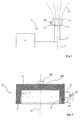
- the figure 1 schematically shows a demining device 1 comprising a current source 2 connected to a magnetic field generator 3 constituted by a cylindrical coil axis 4 which is integral with a vehicle (not shown).
- the coil 3 is shown here capped by a test device 5 according to the invention.
- the figure 2 shows in section an embodiment of this test device 5.
- the latter comprises a housing 6 delimiting a cylindrical bore 7 of axis 25 intended to cap the coil 3 and which therefore has a diameter substantially equal to the outer diameter of the coil 3.
- the housing 6 comprises a cylindrical notch 8 in which is positioned a winding a conductor forming a winding 9.
- the winding 9 can be secured to the housing 6 by overmolding or gluing.
- the winding 9 is connected to a measurement electronics 10 disposed in a box 11 integral with the housing 6.
- the measurement electronics 10 is connected to a display means 12 constituted by a light.
- the winding 9 and the measurement electronics 10 constitute a means for evaluating the level of the magnetic field.
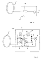
- the figure 3 shows an exemplary embodiment of this evaluation means.
- the winding 9 is connected to the indicator light 12 via a circuit comprising at least one calibrated resistor 10.
- the circuit thus formed does not include a source of energy. It is supplied with current by the winding 9 when the latter is crossed by the field lines 13 ( figure 1 ) generated by the generator 3 and that this field varies as a function of time.
- the value of the calibrated resistor 10 is chosen as a function of the level of the magnetic field that is to be tested.
- the electromotive force of the winding is proportional to the intensity of the magnetic field and is moreover proportional to the frequency of variation of this field.
- the number of turns of the winding 9 will be chosen so as to ensure (when coupled with one of the generators 3 to be tested) a level of induced current intensity sufficient to enable the indicator 12 to light up.
- the device according to the invention is therefore particularly simple and rustic.
- the indicator can only light if a variable magnetic field is present.
- the device thus makes it possible to highlight two types of fault: the failure in which the field is of insufficient level and the failure in which the field is continuous even if its level is sufficient in absolute value.
- the proper functioning of the generator is marked by the ignition and periodic extinction of the indicator 12.
- the ignition frequency corresponds to that of the magnetic field generated.
- dashed lines are shown on the figure 2 a light 12a which is disposed at an upper face of the device 5 and which is connected to a measurement electronics 10a embedded in the body of the device.
- a circuit comprising a filter bandpass and peak level detector, circuit designed to deliver a continuous signal which is an image of the peak-to-peak amplitude of the voltage generated by induction in the coil 9, thus also the amplitude of the magnetic field received.
- This signal may be directed to a comparator which will receive a constant signal supplied by a setpoint means.
- the comparator will control the lighting of the indicator if the signal received is greater than or equal to the setpoint.
- the power supply of the measurement electronics will be provided from the current which is induced by the magnetic field in the winding.
- This embodiment will make it possible to adapt the device to different types of generators by modifying the setpoint value.
- the figure 4 shows a test device according to a second embodiment of the invention.
- the evaluation electronics 10 comprises two distinct evaluation channels 14 and 15 which each make it possible to test a different magnetic field frequency.
- demining devices operating at different frequencies of use, for example low-frequency demining devices (frequency of the order of ten Hertz) and high-frequency mine clearance devices (greater than one kilo). Hertz). These devices operating at high and low frequency can also be associated on the same vehicle.
- Each evaluation channel 14, 15 comprises a filtering stage 16, 17 followed by an evaluation stage 18, 19.
- Each filter stage 16, 17 is produced in a conventional manner by the combination of resistors and capacitors. It allows to pass to the evaluator 18 or 19 considered only the portion of the signal provided by the coil 9 and which corresponds to the frequency sought by the evaluation channel.
- the low-frequency filtering stage 16 will be calibrated to let the frequencies of the order of ten Hz and the high-frequency filtering stage 17 will be defined to pass frequencies above kHz.
- the winding 9 supplies a power storage module 20.
- This module associates, for example, a diode 21 and a capacitor 22.
- the alternating current supplied by the winding 9 makes it possible to charge the capacitor 22.
- This module 20 has the function, on the one hand to supply power to the evaluators 18 and 19, and on the other hand to ensure the supply of energy to the indicator 12.
- the evaluation modules 18 and 19 comprise a calibration stage 18a, 19a which makes it possible to retain only a fraction of the voltage coming from the filter 16, 17. This adjusts the sensitivity of the detection for each evaluation channel.
- These calibration stages will in a conventional manner comprise a rectifier followed by a resistor bridge.
- the calibration stages 18a, 19a are connected to an oscillator 18b, 19b (in the form of integrated circuits). Each oscillator will be calibrated at a well-defined frequency which will be chosen different for the high frequency channel 15 and for the low frequency channel 14.
- the calibration signals provided by the stages 18a, 19a will thus be applied at the "reset" (reset) input of each oscillator. This will have the effect of controlling the emission or not of a signal by the oscillator considered.
- the calibration stage considered (18a or 19a) applies a voltage to the input RAZ of the oscillator 18b or 19b. The latter is then unlocked and it supplies a periodic current to the indicator 12 which causes a periodic ignition of this indicator with the frequency that has been associated by adjustment to the oscillator 18b, 19b considered. If the stages 14 or 15 do not detect current, the oscillators are blocked and the indicator 12 remains off. Diodes 23, 24 are arranged between each oscillator and the indicator light 12. The combination of these two diodes constitutes an OR logic gate. The indicator light 12 is thus lit indifferently by one or the other of the evaluation channels 14, 15.
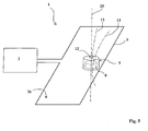
- the figure 5 shows the test device 5 implemented to control a demining device 1 operating at high frequency.
- This demining device also comprises a current source 2 which is connected to a magnetic field generator 3 constituted by one or more conductive turns, which are for example integral with a mechanical member integral with a vehicle, for example a demining plow.
- the test device 5 according to the invention is positioned near the coil or turns 3.
- the axis 25 of the test device 5 will be disposed substantially perpendicular to the plane 26 of the coil (most often the axis 25 is substantially vertical). In such a position, the lines 13 of the magnetic field generated by the generator 3 pass through the winding 9 of the device 5 which can therefore operate.
- the device 5 shown in FIG. figure 5 comprises a single indicator 12 disposed at an upper face of the device 5. This indicator is visible in all directions of space.
- An appropriate optical device may be provided to ensure the diffusion of the radiation along 360 °. It can thus be seen that the device according to this embodiment of the invention makes it possible to test a low frequency deminer just as easily as shown in FIG. figure 1 a high-frequency deminer as depicted in figure 5 .
- the device has no on-board power source, control button or adjustment means. It is extremely hardy and makes it possible to check the presence of an alternating magnetic field of a given intensity (no lighting of the indicator if the field is absent or continuous, if it is of insufficient level, or if it does not is not in the right frequency band). It also makes it possible to test generators operating according to frequencies different without intervention or special adjustment on the device.
- the lighting frequencies of the indicator which are different for the high or low frequency generators, can be easily detected by a user, even inexperienced.
Abstract
Description
Le domaine technique de l'invention est celui des dispositifs permettant de tester le fonctionnement d'un générateur de champ magnétique.The technical field of the invention is that of devices for testing the operation of a magnetic field generator.
L'invention est plus particulièrement adaptée au test des bobines utilisées dans les systèmes de déminage.The invention is more particularly suitable for testing coils used in demining systems.
On connaît par le brevet
Ce dispositif comprend un capteur de champ magnétique couplé à un circuit électronique de traitement du signal. Le circuit assure une comparaison entre le signal détecté et une valeur de consigne. Il fournit le résultat de la comparaison à l'aide d'un afficheur.This device comprises a magnetic field sensor coupled to an electronic signal processing circuit. The circuit compares the detected signal with a set value. It provides the result of the comparison using a display.
Ce dispositif est bien adapté pour la réalisation de cartographies du champ magnétique à distance du générateur et pour assurer une mesure du niveau du champ (à l'aide d'un moyen permettant de faire varier la valeur de consigne).This device is well suited for performing mappings of the magnetic field remote from the generator and to ensure a measurement of the field level (using a means for varying the setpoint).
Il est par contre d'emploi trop complexe pour permettre la simple validation ou vérification du bon fonctionnement d'un générateur. Par ailleurs la sensibilité du capteur est maximale suivant une direction bien définie qui doit être repérée par rapport au générateur pour éviter une erreur d'évaluation.However, it is too complex to use to simply validate or verify the proper functioning of a generator. Moreover, the sensitivity of the sensor is maximum along a well-defined direction which must be identified relative to the generator to avoid an evaluation error.
Il existe donc un besoin d'un dispositif de test rustique et bon marché permettant de valider d'une façon fiable le bon fonctionnement d'un générateur de champ magnétique.There is therefore a need for a cheap and rustic test device for reliably validating the proper operation of a magnetic field generator.
L'invention a pour but de fournir un tel dispositif.The object of the invention is to provide such a device.
Ainsi l'invention a pour objet un dispositif de test du fonctionnement d'un générateur de champ magnétique, et notamment d'une bobine de déminage, dispositif comprenant au moins un moyen d'évaluation du niveau du champ magnétique couplé à au moins un moyen d'affichage, le moyen d'évaluation comprenant au moins un bobinage pouvant être positionné de façon à être traversé par les lignes du champ magnétique, bobinage relié à une électronique d'évaluation qui est alimentée en courant par le bobinage lui-même, dispositif caractérisé en ce que l'électronique d'évaluation comprend au moins deux voies d'évaluation distinctes permettant chacune de tester une fréquence de champ magnétique différente, les deux voies d'évaluation étant couplées simultanément au même moyen d'affichage et au travers d'une porte logique OU.Thus, the subject of the invention is a device for testing the operation of a magnetic field generator, and in particular a demining coil, which device comprises at least one means for evaluating the level of the magnetic field coupled to at least one means. display, the evaluation means comprising at least one winding which can be positioned so as to be traversed by the lines of the magnetic field, a winding connected to an evaluation electronics which is supplied with current by the winding itself, characterized in that the evaluation electronics comprises at least two separate evaluation channels each for testing a different magnetic field frequency, the two evaluation channels being simultaneously coupled to the same display means and through an OR logic gate.
Selon un mode de réalisation, chaque voie d'évaluation associe un étage de filtrage et un étage d'évaluation.According to one embodiment, each evaluation channel associates a filtering stage and an evaluation stage.
Selon un autre mode de réalisation, l'électronique d'évaluation associe une voie d'évaluation configurée pour une fréquence de l'ordre de la dizaine de Hz et une voie d'évaluation configurée pour une fréquence supérieure au kilo Hz.According to another embodiment, the evaluation electronics associates an evaluation channel configured for a frequency of the order of ten Hz and an evaluation channel configured for a frequency greater than one kilo Hz.
Selon un autre mode de réalisation, chaque étage d'évaluation comprend un oscillateur qui est calibré à une fréquence distincte pour la voie haute fréquence et pour la voie basse fréquence, chaque oscillateur assurant ainsi le fonctionnement du moyen d'affichage avec une fréquence distincte.According to another embodiment, each evaluation stage comprises an oscillator which is calibrated at a distinct frequency for the high frequency channel and for the low frequency channel, each oscillator thus ensuring the operation of the display means with a distinct frequency.
Selon un autre mode de réalisation, l'électronique d'évaluation comprend un module de stockage d'énergie comportant au moins une capacité.According to another embodiment, the evaluation electronics comprises an energy storage module comprising at least one capacitor.
Selon un autre mode de réalisation, le moyen d'affichage comprend au moins un voyant lumineux.According to another embodiment, the display means comprises at least one indicator light.
Selon un autre mode de réalisation, le moyen d'affichage comprend un voyant lumineux unique disposé au niveau d'une face supérieure du dispositif.According to another embodiment, the display means comprises a single indicator light disposed at an upper face of the device.
Selon un autre mode de réalisation, le bobinage est solidaire d'un boîtier délimitant un alésage destiné à coiffer un générateur à tester.According to another embodiment, the winding is secured to a housing defining a bore for capping a generator to be tested.
L'invention sera mieux comprise à la lecture de la description qui va suivre d'un mode particulier de réalisation, description faite en référence aux dessins annexés et dans lesquels :
- la
figure 1 est un schéma montrant la mise en place d'un dispositif selon l'invention sur une bobine de déminage, - la
figure 2 est une vue en coupe d'un dispositif selon un mode de réalisation de l'invention, - la
figure 3 est un schéma d'un mode de réalisation du moyen d'évaluation du dispositif selon l'invention, - la
figure 4 est un schéma d'un deuxième mode de réalisation du moyen d'évaluation du dispositif selon l'invention, - la
figure 5 est un schéma montrant la mise en place d'un dispositif selon ce dernier mode de réalisation de l'invention pour tester une bobine de déminage fonctionnant à haute fréquence.
- the
figure 1 is a diagram showing the implementation of a device according to the invention on a de-mining coil, - the
figure 2 is a sectional view of a device according to one embodiment of the invention, - the
figure 3 is a diagram of an embodiment of the evaluation means of the device according to the invention, - the
figure 4 is a diagram of a second embodiment of the evaluation means of the device according to the invention, - the
figure 5 is a diagram showing the establishment of a device according to this last embodiment of the invention for testing a mine coil operating at high frequency.
La
Un tel dispositif de déminage est décrit par le brevet
La bobine 3 est représentée ici coiffée par un dispositif de test 5 selon l'invention.The
La
Ce dernier comprend un boîtier 6 délimitant un alésage cylindrique 7 d'axe 25 destiné à coiffer la bobine 3 et qui a donc un diamètre sensiblement égal au diamètre externe de la bobine 3. Le boîtier 6 comporte une encoche cylindrique 8 dans laquelle est positionné un enroulement d'un conducteur formant un bobinage 9. Le bobinage 9 pourra être rendu solidaire du boîtier 6 par surmoulage ou par collage.The latter comprises a
Le bobinage 9 est relié à une électronique de mesure 10 disposée dans un coffret 11 solidaire du boîtier 6. L'électronique de mesure 10 est reliée à un moyen d'affichage 12 constitué par un voyant. Le bobinage 9 et l'électronique de mesure 10 constituent un moyen d'évaluation du niveau du champ magnétique.The
La
Le circuit ainsi constitué ne comprend pas de source d'énergie. Il est alimenté en courant par le bobinage 9 lorsque ce dernier est traversé par les lignes de champ 13 (
La valeur de la résistance calibrée 10 est choisie en fonction du niveau du champ magnétique que l'on cherche à tester.The value of the
Pour un bobinage donné, la force électromotrice du bobinage est proportionnelle à l'intensité du champ magnétique et elle est par ailleurs proportionnelle à la fréquence de variation de ce champ.For a given winding, the electromotive force of the winding is proportional to the intensity of the magnetic field and is moreover proportional to the frequency of variation of this field.
L'Homme du Métier choisira la valeur de la résistance de telle sorte que le voyant 12 ne s'allume que si le champ magnétique a les caractéristiques souhaitées du point de vue de l'intensité et de la fréquence.Those skilled in the art will choose the value of the resistor so that the
Par ailleurs le nombre de spires du bobinage 9 sera choisi de façon à assurer (lorsqu'il est couplé avec un des générateurs 3 à tester) un niveau d'intensité de courant induit suffisant pour permettre l'allumage du voyant 12.Moreover, the number of turns of the winding 9 will be chosen so as to ensure (when coupled with one of the
Le dispositif selon l'invention est donc particulièrement simple et rustique. Par ailleurs le voyant ne peut s'allumer que si un champ magnétique variable est présent.The device according to the invention is therefore particularly simple and rustic. In addition, the indicator can only light if a variable magnetic field is present.
Le dispositif permet donc de mettre en évidence deux types de défaut : la panne dans laquelle le champ est de niveau insuffisant et la panne dans laquelle le champ est continu même si son niveau est suffisant en valeur absolue.The device thus makes it possible to highlight two types of fault: the failure in which the field is of insufficient level and the failure in which the field is continuous even if its level is sufficient in absolute value.
Le bon fonctionnement du générateur est repéré par l'allumage et l'extinction périodique du voyant 12. La fréquence d'allumage correspond à celle du champ magnétique engendré.The proper functioning of the generator is marked by the ignition and periodic extinction of the
Différentes variantes sont possibles sans sortir du cadre de l'invention. Il est possible de prévoir plusieurs voyants 12 orientés de façon différente, cela afin de faciliter le repérage du bon fonctionnement pour un opérateur situé à distance.Different variants are possible without departing from the scope of the invention. It is possible to provide
A titre d'exemple on a représenté en pointillés sur la
Il est bien entendu possible de mettre en oeuvre l'invention avec une électronique de mesure différente. On pourra par exemple prévoir un circuit comprenant un filtre passe bande et détecteur de niveau crête, circuit conçu de façon à délivrer un signal continu qui est une image de l'amplitude crête à crête de la tension engendrée par induction dans le bobinage 9, donc également de l'amplitude du champ magnétique reçu.It is of course possible to implement the invention with a different measurement electronics. For example, it is possible to provide a circuit comprising a filter bandpass and peak level detector, circuit designed to deliver a continuous signal which is an image of the peak-to-peak amplitude of the voltage generated by induction in the
Ce signal pourra être dirigé vers un comparateur qui recevra un signal constant fourni par un moyen de consigne. Le comparateur commandera l'allumage du voyant si le signal reçu est supérieur ou égal à la consigne.This signal may be directed to a comparator which will receive a constant signal supplied by a setpoint means. The comparator will control the lighting of the indicator if the signal received is greater than or equal to the setpoint.
On assurera là encore l'alimentation en énergie électrique de l'électronique de mesure à partir du courant qui est induit par le champ magnétique dans le bobinage.Here again the power supply of the measurement electronics will be provided from the current which is induced by the magnetic field in the winding.
Ce mode de réalisation permettra d'adapter le dispositif à différents types de générateurs en modifiant la valeur de consigne.This embodiment will make it possible to adapt the device to different types of generators by modifying the setpoint value.
La
Suivant ce mode l'électronique d'évaluation 10 comprend deux voies d'évaluations distinctes 14 et 15 qui permettent chacune de tester une fréquence de champ magnétique différente.In this mode, the
Il existe en effet des dispositifs de déminage fonctionnant suivant des fréquences d'emploi différentes, par exemple des dispositifs de déminage à basse fréquence (fréquence de l'ordre de la dizaine de Hertz) et des dispositifs de déminage à haute fréquence (supérieure au kilo Hertz). Ces dispositifs fonctionnant à haute et à basse fréquence peuvent par ailleurs être associés sur un même véhicule.There are indeed demining devices operating at different frequencies of use, for example low-frequency demining devices (frequency of the order of ten Hertz) and high-frequency mine clearance devices (greater than one kilo). Hertz). These devices operating at high and low frequency can also be associated on the same vehicle.
Chaque voie d'évaluation 14, 15 comprend un étage de filtrage 16, 17 suivi d'un étage d'évaluation 18, 19.Each
Chaque étage de filtrage 16, 17 est réalisé d'une façon classique par l'association de résistances et de capacités. Il permet de ne laisser passer vers l'évaluateur 18 ou 19 considéré que la partie du signal fournie par le bobinage 9 et qui correspond à la fréquence recherchée par la voie d'évaluation.Each
Par exemple, l'étage de filtrage basse fréquence 16 sera calibré pour laisser passer les fréquences de l'ordre de la dizaine de Hz et l'étage de filtrage haute fréquence 17 sera défini pour laisser passer les fréquences supérieures au kHz.For example, the low-
Parallèlement aux étages de filtrage 16,17, le bobinage 9 alimente un module de stockage d'énergie 20. Ce module associe par exemple une diode 21 et une capacité 22.In parallel with the filtering stages 16, 17, the winding 9 supplies a
Le courant alternatif fourni par le bobinage 9 permet de charger la capacité 22.The alternating current supplied by the winding 9 makes it possible to charge the
Ce module 20 a pour fonction, d'une part d'alimenter en énergie les évaluateurs 18 et 19, et d'autre part d'assurer la fourniture d'énergie au voyant 12.This
Les modules d'évaluation 18 et 19 comprennent un étage de calibration 18a,19a qui permet de ne retenir qu'une fraction de la tension issue du filtre 16,17. On règle ainsi la sensibilité de la détection pour chaque voie d'évaluation. Ces étages de calibration comprendront d'une façon classique un redresseur suivi d'un pont de résistances.The
Les étages de calibration 18a,19a sont raccordés à un oscillateur 18b, 19b (réalisé sous la forme de circuits intégrés). Chaque oscillateur sera calibré à une fréquence bien définie qui sera choisie différente pour la voie haute fréquence 15 et pour la voie basse fréquence 14.The calibration stages 18a, 19a are connected to an
On appliquera ainsi les signaux de calibration fournis par les étages 18a,19a au niveau de l'entrée "remise à zéro" (RAZ) de chaque oscillateur. Ceci aura pour effet de commander l'émission ou non d'un signal par l'oscillateur considéré.The calibration signals provided by the
Si un courant de la fréquence recherché est détecté par un des étages 14 ou 15, l'étage de calibration considéré (18a ou 19a) applique une tension à l'entrée RAZ de l'oscillateur 18b ou 19b. Ce dernier est alors débloqué et il fournit un courant périodique au voyant 12 ce qui provoque un allumage périodique de ce voyant avec la fréquence qui a été associée par réglage à l'oscillateur 18b,19b considéré. Si les étages 14 ou 15 ne détectent pas de courant, les oscillateurs sont bloqués et le voyant 12 reste éteint. Des diodes 23,24 sont disposées entre chaque oscillateur et le voyant 12. La combinaison de ces deux diodes constitue une porte logique OU. Le voyant 12 est donc allumé indifféremment par l'une ou l'autre des voies d'évaluation 14,15.If a current of the desired frequency is detected by one of the
La
Le dispositif 5 représenté à la
Le dispositif ne comporte aucune source d'énergie embarquée, aucun bouton de commande ni aucun moyen de réglage. Il est extrêmement rustique et permet de vérifier la présence d'un champ magnétique alternatif d'une intensité donnée (pas d'allumage du voyant si le champ est absent ou continu, s'il est de niveau insuffisant, ou s'il n'est pas dans la bonne bande de fréquence). Il permet aussi de tester des générateurs fonctionnant suivant des fréquences différentes sans intervention ni réglage particulier sur le dispositif.The device has no on-board power source, control button or adjustment means. It is extremely hardy and makes it possible to check the presence of an alternating magnetic field of a given intensity (no lighting of the indicator if the field is absent or continuous, if it is of insufficient level, or if it does not is not in the right frequency band). It also makes it possible to test generators operating according to frequencies different without intervention or special adjustment on the device.
Par ailleurs les fréquences d'allumage du voyant, qui sont différentes pour les générateurs haute ou basse fréquence, peuvent être aisément détectées par un utilisateur, même inexpérimenté.Moreover, the lighting frequencies of the indicator, which are different for the high or low frequency generators, can be easily detected by a user, even inexperienced.
Claims (8)
Applications Claiming Priority (1)
| Application Number | Priority Date | Filing Date | Title |
|---|---|---|---|
| FR0707024A FR2922027B1 (en) | 2007-10-08 | 2007-10-08 | DEVICE FOR TESTING THE OPERATION OF A MAGNETIC FIELD GENERATOR |
Publications (2)
| Publication Number | Publication Date |
|---|---|
| EP2048510A1 true EP2048510A1 (en) | 2009-04-15 |
| EP2048510B1 EP2048510B1 (en) | 2011-09-28 |
Family
ID=39410091
Family Applications (1)
| Application Number | Title | Priority Date | Filing Date |
|---|---|---|---|
| EP08290929A Active EP2048510B1 (en) | 2007-10-08 | 2008-10-02 | Device for testing the operation of a magnetic field generator |
Country Status (6)
| Country | Link |
|---|---|
| US (1) | US8143886B2 (en) |
| EP (1) | EP2048510B1 (en) |
| AT (1) | ATE526590T1 (en) |
| DK (1) | DK2048510T3 (en) |
| ES (1) | ES2373612T3 (en) |
| FR (1) | FR2922027B1 (en) |
Families Citing this family (2)
| Publication number | Priority date | Publication date | Assignee | Title |
|---|---|---|---|---|
| WO2010098884A1 (en) | 2009-02-26 | 2010-09-02 | Jian-Ping Wang | High magnetic moment particle detection |
| US8904937B2 (en) | 2012-04-13 | 2014-12-09 | C-2 Innovations Inc. | Line charge |
Citations (8)
| Publication number | Priority date | Publication date | Assignee | Title |
|---|---|---|---|---|
| US5256960A (en) * | 1991-04-09 | 1993-10-26 | Novini Amir R | Portable dual band electromagnetic field radiation measurement apparatus |
| US5440232A (en) * | 1993-12-06 | 1995-08-08 | The United States Of America As Represented By The Secretary Of The Navy | System for monitoring and analyzing field energy exposure |
| FR2750204A1 (en) | 1996-06-19 | 1997-12-26 | Giat Ind Sa | DEMINING COIL AND DEVICE FOR DEMINING THE SAME |
| FR2779529A1 (en) | 1998-06-05 | 1999-12-10 | Giat Ind Sa | Magnetic field strength determination device for a variable magnetic field generator, used to determine whether generator is working effectively for use with mine clearance devices |
| US6204661B1 (en) * | 1998-09-30 | 2001-03-20 | Tech International Corp. | Detector for periodic magnetic field |
| US20020101226A1 (en) * | 1997-02-03 | 2002-08-01 | Bartulos Jorge Raul | Passive system for the detection and indication of non-ionizing electromagnetic radiations and static electricity, especially designed to be applied to or integrated in any type of anti-radiation/anti-static/anti-reflection filter intended to block said emissions, particularly in devices with cathode ray tubes (CRT) |
| US6486664B1 (en) * | 1998-07-01 | 2002-11-26 | Lepel Corp. | Magnetic field exposure sensor and analysis system |
| US6809520B1 (en) * | 2001-12-04 | 2004-10-26 | The Johns Hopkins University | Compact, autonomous robotic detection and identification sensor system of unexploded ordnance site remediation |
Family Cites Families (12)
| Publication number | Priority date | Publication date | Assignee | Title |
|---|---|---|---|---|
| US3248645A (en) * | 1962-02-28 | 1966-04-26 | Radio Frequency Lab Inc | Gaussmeter |
| CA1267192A (en) * | 1987-04-24 | 1990-03-27 | John E. Mcfee | Ferrous object locator and classifier |
| JPH04136981A (en) * | 1990-09-28 | 1992-05-11 | Sharp Corp | Driver circuit for display device |
| EP0536447A1 (en) * | 1991-10-11 | 1993-04-14 | Koninklijke Emballage Industrie Van Leer B.V. | Exposure meter for use with induction heat sealing of containers |
| US5467084A (en) * | 1994-03-28 | 1995-11-14 | Jervis B. Webb Company | Vehicle position determining apparatus |
| FR2730557B1 (en) * | 1995-02-10 | 1997-04-11 | Giat Ind Sa | EXERCISE MINE, PROGRAMMING DEVICE, AND SIMULATION DEVICE IMPLEMENTING SUCH A MINE |
| US5773974A (en) * | 1995-04-13 | 1998-06-30 | Credence Technologies, Inc. | Portable electro-magnetic field detection and measurement apparatus for near-field test and measurements |
| DE19701753A1 (en) * | 1997-01-20 | 1998-07-23 | Aichinger Helmuth | Magnetic field change tracker for electrical disturbance |
| FR2814242B1 (en) * | 2000-09-19 | 2002-12-20 | France Telecom | DEVICE FOR PUNCTUAL MEASUREMENT OF A MAGNETIC FIELD RADIOFREQUENCY OF CONSTANT AMPLITUDE AND FREQUENCY |
| TW534983B (en) * | 2001-07-31 | 2003-06-01 | Snap On Tech Inc | Coil on plug inductive sampling method and apparatus |
| JP3896489B2 (en) * | 2004-07-16 | 2007-03-22 | 国立大学法人 岡山大学 | Magnetic detection device and substance determination device |
| US7437986B2 (en) * | 2005-08-25 | 2008-10-21 | Nanyang Technological University | Landmine avoidance and protection device |
-
2007
- 2007-10-08 FR FR0707024A patent/FR2922027B1/en not_active Expired - Fee Related
-
2008
- 2008-09-29 US US12/285,097 patent/US8143886B2/en active Active
- 2008-10-02 AT AT08290929T patent/ATE526590T1/en not_active IP Right Cessation
- 2008-10-02 DK DK08290929.2T patent/DK2048510T3/en active
- 2008-10-02 ES ES08290929T patent/ES2373612T3/en active Active
- 2008-10-02 EP EP08290929A patent/EP2048510B1/en active Active
Patent Citations (8)
| Publication number | Priority date | Publication date | Assignee | Title |
|---|---|---|---|---|
| US5256960A (en) * | 1991-04-09 | 1993-10-26 | Novini Amir R | Portable dual band electromagnetic field radiation measurement apparatus |
| US5440232A (en) * | 1993-12-06 | 1995-08-08 | The United States Of America As Represented By The Secretary Of The Navy | System for monitoring and analyzing field energy exposure |
| FR2750204A1 (en) | 1996-06-19 | 1997-12-26 | Giat Ind Sa | DEMINING COIL AND DEVICE FOR DEMINING THE SAME |
| US20020101226A1 (en) * | 1997-02-03 | 2002-08-01 | Bartulos Jorge Raul | Passive system for the detection and indication of non-ionizing electromagnetic radiations and static electricity, especially designed to be applied to or integrated in any type of anti-radiation/anti-static/anti-reflection filter intended to block said emissions, particularly in devices with cathode ray tubes (CRT) |
| FR2779529A1 (en) | 1998-06-05 | 1999-12-10 | Giat Ind Sa | Magnetic field strength determination device for a variable magnetic field generator, used to determine whether generator is working effectively for use with mine clearance devices |
| US6486664B1 (en) * | 1998-07-01 | 2002-11-26 | Lepel Corp. | Magnetic field exposure sensor and analysis system |
| US6204661B1 (en) * | 1998-09-30 | 2001-03-20 | Tech International Corp. | Detector for periodic magnetic field |
| US6809520B1 (en) * | 2001-12-04 | 2004-10-26 | The Johns Hopkins University | Compact, autonomous robotic detection and identification sensor system of unexploded ordnance site remediation |
Also Published As
| Publication number | Publication date |
|---|---|
| DK2048510T3 (en) | 2011-11-07 |
| US20090091319A1 (en) | 2009-04-09 |
| US8143886B2 (en) | 2012-03-27 |
| ES2373612T3 (en) | 2012-02-07 |
| EP2048510B1 (en) | 2011-09-28 |
| ATE526590T1 (en) | 2011-10-15 |
| FR2922027B1 (en) | 2011-04-29 |
| FR2922027A1 (en) | 2009-04-10 |
Similar Documents
| Publication | Publication Date | Title |
|---|---|---|
| CA2831353C (en) | Method and system for detecting a short-circuit affecting a sensor | |
| FR2792406A1 (en) | METHOD FOR CONTROLLING AN ELECTROMAGNETIC FLOWMETER, AND ELECTROMAGNETIC FLOWMETER | |
| FR3007820A1 (en) | SECURE OPTICAL MODULE FOR MOTOR VEHICLE COMPRISING A LASER SOURCE | |
| FR3055961A1 (en) | ROTATION ANGLE SENSOR AND STATOR EQUIPPED WITH SUCH SENSOR | |
| EP2048510B1 (en) | Device for testing the operation of a magnetic field generator | |
| EP0176448A2 (en) | Detector of a light beam with a photodiode and bias control circuit | |
| WO2019091740A1 (en) | Differential protection device using the rectified average voltage | |
| EP2395315B1 (en) | Test method and system for an electro-pyrotechnical initiator | |
| EP2993962B1 (en) | Device for transmitting an electric parametrisation signal to a control device of an led lighting module, associated power supply system, lighting assembly and transmission method | |
| FR2841826A1 (en) | WHEEL AND TIRE ASSEMBLY FOR A MOTOR VEHICLE WITH WEAR INDICATOR, WEAR AND TIRE INDICATOR DEVICE FOR SUCH AN ASSEMBLY | |
| EP2463669B1 (en) | Voltage detection module | |
| WO2019091739A1 (en) | Differential protection device with filtering of the carrier of the excitation signal | |
| FR3059783A1 (en) | METHOD FOR MANUFACTURING A MEASUREMENT SENSOR FOR A CIRCUIT BREAKER | |
| FR3098294A1 (en) | Device for measuring the spacing of two parts of a catenary tensioning device | |
| FR3006056A1 (en) | METHOD FOR MEASURING MAGNETIC EFFECT ELECTRIC CURRENT STRONG AND CORRESPONDING MEASURING DEVICE | |
| WO2021259922A1 (en) | Method for detecting leakage or fault currents in an electrical installation using a protective device providing at least differential protection and such a device suitable for implementing the method | |
| EP3654045B1 (en) | Method for detecting and transmitting information about a dormant failure | |
| EP0609113B1 (en) | Device for measuring an electric DC-parameter, like a voltage | |
| EP3159704B1 (en) | Measuring chain for a signalling electronic circuit | |
| FR2577350A1 (en) | CONTROL DEVICE FOR THE COMPENSATION OF THE ZERO OHOM VOLTAGE OF HALL GENERATORS, COMPRISING A VOLTAGE DIVIDER WHOSE OUTLET IS CONNECTED WITH ONE OF THE HALL ELECTRODES | |
| FR2646907A1 (en) | Device for measuring the level and/or volume of liquid in a tank | |
| EP0553001A1 (en) | Method and system for test of function and/or for the presence of elements connected in parallel | |
| FR2577656A1 (en) | Device for checking the amount of gas filling a vessel | |
| FR2715869A1 (en) | High frequency industrial treatment installation using two signals | |
| FR2826722A1 (en) | METHOD AND CIRCUIT FOR DETECTING A FERROMAGNETIC ELEMENT |
Legal Events
| Date | Code | Title | Description |
|---|---|---|---|
| PUAI | Public reference made under article 153(3) epc to a published international application that has entered the european phase |
Free format text: ORIGINAL CODE: 0009012 |
|
| AK | Designated contracting states |
Kind code of ref document: A1 Designated state(s): AT BE BG CH CY CZ DE DK EE ES FI FR GB GR HR HU IE IS IT LI LT LU LV MC MT NL NO PL PT RO SE SI SK TR |
|
| AX | Request for extension of the european patent |
Extension state: AL BA MK RS |
|
| 17P | Request for examination filed |
Effective date: 20091015 |
|
| 17Q | First examination report despatched |
Effective date: 20091111 |
|
| AKX | Designation fees paid |
Designated state(s): AT BE BG CH CY CZ DE DK EE ES FI FR GB GR HR HU IE IS IT LI LT LU LV MC MT NL NO PL PT RO SE SI SK TR |
|
| GRAP | Despatch of communication of intention to grant a patent |
Free format text: ORIGINAL CODE: EPIDOSNIGR1 |
|
| GRAS | Grant fee paid |
Free format text: ORIGINAL CODE: EPIDOSNIGR3 |
|
| GRAA | (expected) grant |
Free format text: ORIGINAL CODE: 0009210 |
|
| AK | Designated contracting states |
Kind code of ref document: B1 Designated state(s): AT BE BG CH CY CZ DE DK EE ES FI FR GB GR HR HU IE IS IT LI LT LU LV MC MT NL NO PL PT RO SE SI SK TR |
|
| REG | Reference to a national code |
Ref country code: GB Ref legal event code: FG4D Free format text: NOT ENGLISH |
|
| REG | Reference to a national code |
Ref country code: CH Ref legal event code: EP |
|
| REG | Reference to a national code |
Ref country code: CH Ref legal event code: NV Representative=s name: ING. MARCO ZARDI C/O M. ZARDI & CO. S.A. |
|
| REG | Reference to a national code |
Ref country code: IE Ref legal event code: FG4D |
|
| REG | Reference to a national code |
Ref country code: DK Ref legal event code: T3 |
|
| REG | Reference to a national code |
Ref country code: DE Ref legal event code: R096 Ref document number: 602008010117 Country of ref document: DE Effective date: 20111201 |
|
| REG | Reference to a national code |
Ref country code: NL Ref legal event code: T3 |
|
| REG | Reference to a national code |
Ref country code: SE Ref legal event code: TRGR |
|
| PG25 | Lapsed in a contracting state [announced via postgrant information from national office to epo] |
Ref country code: HR Free format text: LAPSE BECAUSE OF FAILURE TO SUBMIT A TRANSLATION OF THE DESCRIPTION OR TO PAY THE FEE WITHIN THE PRESCRIBED TIME-LIMIT Effective date: 20110928 Ref country code: FI Free format text: LAPSE BECAUSE OF FAILURE TO SUBMIT A TRANSLATION OF THE DESCRIPTION OR TO PAY THE FEE WITHIN THE PRESCRIBED TIME-LIMIT Effective date: 20110928 Ref country code: LT Free format text: LAPSE BECAUSE OF FAILURE TO SUBMIT A TRANSLATION OF THE DESCRIPTION OR TO PAY THE FEE WITHIN THE PRESCRIBED TIME-LIMIT Effective date: 20110928 |
|
| REG | Reference to a national code |
Ref country code: ES Ref legal event code: FG2A Ref document number: 2373612 Country of ref document: ES Kind code of ref document: T3 Effective date: 20120207 |
|
| REG | Reference to a national code |
Ref country code: NO Ref legal event code: T2 Effective date: 20110928 |
|
| LTIE | Lt: invalidation of european patent or patent extension |
Effective date: 20110928 |
|
| PG25 | Lapsed in a contracting state [announced via postgrant information from national office to epo] |
Ref country code: AT Free format text: LAPSE BECAUSE OF FAILURE TO SUBMIT A TRANSLATION OF THE DESCRIPTION OR TO PAY THE FEE WITHIN THE PRESCRIBED TIME-LIMIT Effective date: 20110928 Ref country code: GR Free format text: LAPSE BECAUSE OF FAILURE TO SUBMIT A TRANSLATION OF THE DESCRIPTION OR TO PAY THE FEE WITHIN THE PRESCRIBED TIME-LIMIT Effective date: 20111229 Ref country code: LV Free format text: LAPSE BECAUSE OF FAILURE TO SUBMIT A TRANSLATION OF THE DESCRIPTION OR TO PAY THE FEE WITHIN THE PRESCRIBED TIME-LIMIT Effective date: 20110928 Ref country code: CY Free format text: LAPSE BECAUSE OF FAILURE TO SUBMIT A TRANSLATION OF THE DESCRIPTION OR TO PAY THE FEE WITHIN THE PRESCRIBED TIME-LIMIT Effective date: 20110928 Ref country code: SI Free format text: LAPSE BECAUSE OF FAILURE TO SUBMIT A TRANSLATION OF THE DESCRIPTION OR TO PAY THE FEE WITHIN THE PRESCRIBED TIME-LIMIT Effective date: 20110928 |
|
| REG | Reference to a national code |
Ref country code: AT Ref legal event code: MK05 Ref document number: 526590 Country of ref document: AT Kind code of ref document: T Effective date: 20110928 |
|
| REG | Reference to a national code |
Ref country code: IE Ref legal event code: FD4D |
|
| BERE | Be: lapsed |
Owner name: NEXTER SYSTEMS Effective date: 20111031 |
|
| PG25 | Lapsed in a contracting state [announced via postgrant information from national office to epo] |
Ref country code: SK Free format text: LAPSE BECAUSE OF FAILURE TO SUBMIT A TRANSLATION OF THE DESCRIPTION OR TO PAY THE FEE WITHIN THE PRESCRIBED TIME-LIMIT Effective date: 20110928 Ref country code: IS Free format text: LAPSE BECAUSE OF FAILURE TO SUBMIT A TRANSLATION OF THE DESCRIPTION OR TO PAY THE FEE WITHIN THE PRESCRIBED TIME-LIMIT Effective date: 20120128 Ref country code: CZ Free format text: LAPSE BECAUSE OF FAILURE TO SUBMIT A TRANSLATION OF THE DESCRIPTION OR TO PAY THE FEE WITHIN THE PRESCRIBED TIME-LIMIT Effective date: 20110928 |
|
| PG25 | Lapsed in a contracting state [announced via postgrant information from national office to epo] |
Ref country code: MC Free format text: LAPSE BECAUSE OF NON-PAYMENT OF DUE FEES Effective date: 20111031 Ref country code: IT Free format text: LAPSE BECAUSE OF FAILURE TO SUBMIT A TRANSLATION OF THE DESCRIPTION OR TO PAY THE FEE WITHIN THE PRESCRIBED TIME-LIMIT Effective date: 20110928 Ref country code: EE Free format text: LAPSE BECAUSE OF FAILURE TO SUBMIT A TRANSLATION OF THE DESCRIPTION OR TO PAY THE FEE WITHIN THE PRESCRIBED TIME-LIMIT Effective date: 20110928 Ref country code: RO Free format text: LAPSE BECAUSE OF FAILURE TO SUBMIT A TRANSLATION OF THE DESCRIPTION OR TO PAY THE FEE WITHIN THE PRESCRIBED TIME-LIMIT Effective date: 20110928 Ref country code: PT Free format text: LAPSE BECAUSE OF FAILURE TO SUBMIT A TRANSLATION OF THE DESCRIPTION OR TO PAY THE FEE WITHIN THE PRESCRIBED TIME-LIMIT Effective date: 20120130 |
|
| PG25 | Lapsed in a contracting state [announced via postgrant information from national office to epo] |
Ref country code: BE Free format text: LAPSE BECAUSE OF NON-PAYMENT OF DUE FEES Effective date: 20111031 Ref country code: IE Free format text: LAPSE BECAUSE OF FAILURE TO SUBMIT A TRANSLATION OF THE DESCRIPTION OR TO PAY THE FEE WITHIN THE PRESCRIBED TIME-LIMIT Effective date: 20110928 |
|
| PLBE | No opposition filed within time limit |
Free format text: ORIGINAL CODE: 0009261 |
|
| STAA | Information on the status of an ep patent application or granted ep patent |
Free format text: STATUS: NO OPPOSITION FILED WITHIN TIME LIMIT |
|
| PG25 | Lapsed in a contracting state [announced via postgrant information from national office to epo] |
Ref country code: PL Free format text: LAPSE BECAUSE OF FAILURE TO SUBMIT A TRANSLATION OF THE DESCRIPTION OR TO PAY THE FEE WITHIN THE PRESCRIBED TIME-LIMIT Effective date: 20110928 |
|
| 26N | No opposition filed |
Effective date: 20120629 |
|
| REG | Reference to a national code |
Ref country code: DE Ref legal event code: R097 Ref document number: 602008010117 Country of ref document: DE Effective date: 20120629 |
|
| PG25 | Lapsed in a contracting state [announced via postgrant information from national office to epo] |
Ref country code: MT Free format text: LAPSE BECAUSE OF FAILURE TO SUBMIT A TRANSLATION OF THE DESCRIPTION OR TO PAY THE FEE WITHIN THE PRESCRIBED TIME-LIMIT Effective date: 20110928 |
|
| PG25 | Lapsed in a contracting state [announced via postgrant information from national office to epo] |
Ref country code: LU Free format text: LAPSE BECAUSE OF NON-PAYMENT OF DUE FEES Effective date: 20111002 |
|
| PG25 | Lapsed in a contracting state [announced via postgrant information from national office to epo] |
Ref country code: BG Free format text: LAPSE BECAUSE OF FAILURE TO SUBMIT A TRANSLATION OF THE DESCRIPTION OR TO PAY THE FEE WITHIN THE PRESCRIBED TIME-LIMIT Effective date: 20111228 |
|
| PG25 | Lapsed in a contracting state [announced via postgrant information from national office to epo] |
Ref country code: HU Free format text: LAPSE BECAUSE OF FAILURE TO SUBMIT A TRANSLATION OF THE DESCRIPTION OR TO PAY THE FEE WITHIN THE PRESCRIBED TIME-LIMIT Effective date: 20110928 |
|
| REG | Reference to a national code |
Ref country code: FR Ref legal event code: PLFP Year of fee payment: 9 |
|
| REG | Reference to a national code |
Ref country code: FR Ref legal event code: PLFP Year of fee payment: 10 |
|
| REG | Reference to a national code |
Ref country code: FR Ref legal event code: PLFP Year of fee payment: 11 |
|
| PGFP | Annual fee paid to national office [announced via postgrant information from national office to epo] |
Ref country code: TR Payment date: 20230925 Year of fee payment: 16 Ref country code: NO Payment date: 20230921 Year of fee payment: 16 Ref country code: NL Payment date: 20230922 Year of fee payment: 16 Ref country code: GB Payment date: 20230920 Year of fee payment: 16 |
|
| PGFP | Annual fee paid to national office [announced via postgrant information from national office to epo] |
Ref country code: SE Payment date: 20230922 Year of fee payment: 16 Ref country code: FR Payment date: 20230920 Year of fee payment: 16 Ref country code: DK Payment date: 20230920 Year of fee payment: 16 |
|
| PGFP | Annual fee paid to national office [announced via postgrant information from national office to epo] |
Ref country code: ES Payment date: 20231102 Year of fee payment: 16 |
|
| PGFP | Annual fee paid to national office [announced via postgrant information from national office to epo] |
Ref country code: DE Payment date: 20230920 Year of fee payment: 16 Ref country code: CH Payment date: 20231102 Year of fee payment: 16 |