EP2056031A1 - Error management system of air conditioner - Google Patents
Error management system of air conditioner Download PDFInfo
- Publication number
- EP2056031A1 EP2056031A1 EP20080251876 EP08251876A EP2056031A1 EP 2056031 A1 EP2056031 A1 EP 2056031A1 EP 20080251876 EP20080251876 EP 20080251876 EP 08251876 A EP08251876 A EP 08251876A EP 2056031 A1 EP2056031 A1 EP 2056031A1
- Authority
- EP
- European Patent Office
- Prior art keywords
- error
- information
- air conditioner
- management system
- service center
- Prior art date
- Legal status (The legal status is an assumption and is not a legal conclusion. Google has not performed a legal analysis and makes no representation as to the accuracy of the status listed.)
- Granted
Links
Images


Classifications
-
- F—MECHANICAL ENGINEERING; LIGHTING; HEATING; WEAPONS; BLASTING
- F24—HEATING; RANGES; VENTILATING
- F24F—AIR-CONDITIONING; AIR-HUMIDIFICATION; VENTILATION; USE OF AIR CURRENTS FOR SCREENING
- F24F11/00—Control or safety arrangements
- F24F11/30—Control or safety arrangements for purposes related to the operation of the system, e.g. for safety or monitoring
- F24F11/32—Responding to malfunctions or emergencies
- F24F11/38—Failure diagnosis
-
- F—MECHANICAL ENGINEERING; LIGHTING; HEATING; WEAPONS; BLASTING
- F24—HEATING; RANGES; VENTILATING
- F24F—AIR-CONDITIONING; AIR-HUMIDIFICATION; VENTILATION; USE OF AIR CURRENTS FOR SCREENING
- F24F11/00—Control or safety arrangements
- F24F11/50—Control or safety arrangements characterised by user interfaces or communication
- F24F11/52—Indication arrangements, e.g. displays
-
- F—MECHANICAL ENGINEERING; LIGHTING; HEATING; WEAPONS; BLASTING
- F24—HEATING; RANGES; VENTILATING
- F24F—AIR-CONDITIONING; AIR-HUMIDIFICATION; VENTILATION; USE OF AIR CURRENTS FOR SCREENING
- F24F11/00—Control or safety arrangements
- F24F11/50—Control or safety arrangements characterised by user interfaces or communication
- F24F11/56—Remote control
- F24F11/57—Remote control using telephone networks
-
- F—MECHANICAL ENGINEERING; LIGHTING; HEATING; WEAPONS; BLASTING
- F24—HEATING; RANGES; VENTILATING
- F24F—AIR-CONDITIONING; AIR-HUMIDIFICATION; VENTILATION; USE OF AIR CURRENTS FOR SCREENING
- F24F11/00—Control or safety arrangements
- F24F11/50—Control or safety arrangements characterised by user interfaces or communication
- F24F11/56—Remote control
- F24F11/58—Remote control using Internet communication
-
- G—PHYSICS
- G06—COMPUTING; CALCULATING OR COUNTING
- G06Q—INFORMATION AND COMMUNICATION TECHNOLOGY [ICT] SPECIALLY ADAPTED FOR ADMINISTRATIVE, COMMERCIAL, FINANCIAL, MANAGERIAL OR SUPERVISORY PURPOSES; SYSTEMS OR METHODS SPECIALLY ADAPTED FOR ADMINISTRATIVE, COMMERCIAL, FINANCIAL, MANAGERIAL OR SUPERVISORY PURPOSES, NOT OTHERWISE PROVIDED FOR
- G06Q50/00—Systems or methods specially adapted for specific business sectors, e.g. utilities or tourism
- G06Q50/10—Services
-
- F—MECHANICAL ENGINEERING; LIGHTING; HEATING; WEAPONS; BLASTING
- F24—HEATING; RANGES; VENTILATING
- F24F—AIR-CONDITIONING; AIR-HUMIDIFICATION; VENTILATION; USE OF AIR CURRENTS FOR SCREENING
- F24F11/00—Control or safety arrangements
- F24F11/30—Control or safety arrangements for purposes related to the operation of the system, e.g. for safety or monitoring
- F24F11/32—Responding to malfunctions or emergencies
Definitions
- the present invention relates to an error management system of an air conditioner, and more particularly, to an error management system of an air conditioner, which can quickly take countermeasures against an error of the air conditioner.
- an error management system of an air conditioner includes an air conditioner including at least one indoor unit and at least one outdoor unit connected to the indoor unit and a controller for monitoring operating states of the respective indoor and outdoor units and collectively or individually controlling the operations thereof.
- the error management system of the air conditioner has the problem that, if an error of the air conditioner is detected, a user can not find information about errors or a countermeasure against errors, thus causing inconvenience until a service man who performs the repair and maintenance of air conditioners arrives, and slowing down the repair of the air conditioner.
- the present invention provides an error management system of an air conditioner, comprising an air conditioner; and a central controller for detecting an error of the air conditioner based on a first error information among operational informations received from the air conditioner and transmitting the first error information to a service center, and receiving return countermeasure information corresponding to the first error information from the service center.
- the error management system of the air conditioner according to the present invention can quickly take countermeasures against an error state because information about errors generated in the air conditioner is transmitted to the service center, and the service center sends back a countermeasure against errors in advance before a service man is sent out.
- a user can quickly take countermeasures against an error because the central controller can display a simple countermeasure against errors in advance before the central controller transmits error information to the service center.
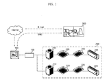
- FIG. 1 is an overall configuration view of an error management system of an air conditioner in accordance with one embodiment of the present invention.
- FIG. 2 is a view showing the configuration of an email transmission system between a central controller and a service center as shown in FIG. 1 .
- the error management system of the air conditioner includes an air conditioner 200, a central controller 100, and a service center 300.
- the air conditioner includes an indoor unit 220 disposed in an indoor space and an outdoor unit 210 disposed in an outdoor space.
- the indoor unit 220 and the outdoor unit 210 are communicatively connected to each other via a network.
- the present invention is not limited thereto, but the air conditioner 200 may include one outdoor unit and a plurality of indoor nits, or, as shown in FIG. 1 , may include a plurality of outdoor units 210 and a plurality of indoor units 220.
- the indoor units 220 are respectively disposed in indoor spaces, and the outdoor unit 210 is disposed in an outdoor space.
- the indoor units 220 and the outdoor unit 220 are communicatively connected via a network through cables.
- the network is an RS-485 communication.
- the 'RS-485 communication' is one of interface protocols for serial communication and a standard for multipoint communication lines.
- the present invention is not limited thereto.
- the central controller 100 is connected to the outdoor unit 210 of the air conditioner 200 to monitor an operating state of the air conditioner 200 and collectively and individually control the operation thereof.
- the central controller 100 may be comprised of an external input device to be connected to the outdoor unit 210 through a communication line, and is communicatively connected to the outdoor unit 210 in order to control the operation of the indoor unit 210 disposed in the indoor space.
- the central controller 100 and the outdoor unit 210 can send and receive data in a variety of ways, including a power line, wireless communication, and LAN as well as RS-485 through cables.
- a protocol converter 150 for converting data sent and received between the central controller 100 and the outdoor unit 210 and data sent and received between the outdoor unit 210 and the indoor unit 220 to and from each other.
- the central controller 100 receives operational informations from the air conditioner 200 in order to monitor the operating state of the air conditioner 200.
- the central controller 100 detects an error of the air conditioner based on the first error information among received operational informations.
- the first error information is information of an error code format about the cause or type of an error when an error occurs to the air conditioner, and is stored in a memory unit (not shown) within the air conditioner 100.
- the air conditioner 200 transmits, to the central controller 100, the first error information of an error code format corresponding to the occurred error.
- the central controller 100 transmits the first error information to the service center 300 located at a remote place, and the service center 300 sends back return countermeasure information corresponding to the first error information to the central controller 100. Specifically, the central controller 100 notifies the service center 300 of the first error information to be transmitted from the air conditioner 200.
- the format of notification can be an error message in a SMS format or in a format like email via the Internet network as a basic format, but not limited thereto.
- an email Me reaches a communication module (310 of FIG. 7 ) of the service center 30 in an SMTP (Small Mail Transfer Protocol) method.
- SMTP Small Mail Transfer Protocol
- the user of the central controller 100 can be set as the sender S_F.
- the communication module 310 of the service center 300 may be a website operated by the service center 300 or a receiving server such as a mail server.
- the email Me contains the first error information E_F, and the service center 300 can clearly find the cause of error occurrence through the email Me transmitted and accumulated. After finding the cause of error occurrence, the service center 300 sends back return countermeasure information corresponding to the first error information to the central controller 100.
- the sendback format may be the SMS format or the format like email via the Internet network as mentioned above. However, the present invention is not limited to the above-stated communication method.
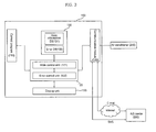
- FIG. 3 is a block diagram showing the internal configuration of the central controller as shown in FIG.1 .
- FIG. 4 is a block diagram showing the internal configuration of an error control unit of the air conditioner as shown in FIG. 3 .
- the central controller 100 includes a database 130, a display unit 150, a control unit 120, and a communication module 140.
- the communication module 140 sends and receives data to and from the air conditioner 140 or the service center 300, and the control unit 120 monitors the operation state of each air conditioner 200 and detects and diagnoses an error by using operational information of the air conditioner 200 received via the communication module 140.
- the central controller 100 further includes a control program 110 for controlling the overall operation of the central controller 100 and providing an interface for operation control to the user of the central controller 100.
- the control unit 120 includes a main control unit 121 for monitoring the state of each air conditioner 200, generating a control signal for operation control according to a control command or setting inputted through the control program 110, and transmitting it to the corresponding outdoor unit 210 or indoor unit 220, and an error control unit 122 for detecting and diagnosing an error of each air conditioner 200 through operational information stored in a state information DB 131, and generating a resultant error message and transmitting it to the service center 300.
- the error control unit 122 further includes an error detection unit 122a for detecting an error of each air conditioner from the first error information among the operational informations, an error diagnosis unit 122b for diagnosing the error detected in the error detection unit 122a, and giving the respective error information a predetermined error level according to the degree of the error, and an error notification module for converting the first error information with an error level given by the error diagnosis unit 122b so as to be transmitted to the service center in an error message in a SMS format or in a format like email through the Internet network.
- the error detection unit 122a is a module for detecting an error of each air conditioner 200.
- the first error information of an error code format is received from the air conditioner 200, it is compared with an error information list stored in the database 130 to judge that an error of the corresponding air conditioner 200 is detected.
- a concrete method of detecting an error can be implemented in various ways other than the above-described method.
- the error diagnosis unit 122b is a module for giving the first error information judged in the error detection unit 122a a predetermined error level according to the degree of the error.
- the error level can be classified into an error that can be handled by the user of the central controller 100, a fatal error requiring immediate response from the service center 300 because the error has a fatal effect on the central controller 100, an error that can be solved when handled within a given number of days in the service center 300, and subsidiary management matters such as filter replacement and regular checkup.
- an error level according to the degree of an error can be set to a variety of levels by the basic setting of the product upon release or the setting by a user.
- the error notification module 122c generates an error message for the respective first error information with an error level given by the error diagnosis unit 122b.
- the error notification module 122c generates an error message containing the first error information, and the error message is transmitted to the service center 300 via the communication module 140.
- the error notification module 122c can convert the first error information into an error message in an email via the Internet or in a SMS format as described above, but it is not limited to the above communication method.
- the error notification module 122c transmits the first error information to the service center 300 only when the respective first error information with an error level given has an error level higher than a preset error level. That is, all the first error information received from the air conditioner 200 is not transmitted to the service center 300, but only an error message containing the first error information of higher than a preset error level is transmitted to the service center 300. In a case where there occurs an error that does not require the repair of the air conditioner 200, or where a temporary error occurs, the error message containing the first error information to be transmitted to the service center 300 may cause overload. For example, since network failures are mostly temporary failures, the error state can be automatically recovered after the lapse of a predetermined time.
- the central controller 100 transmits an error message containing the first error information to the service center 300 only when the first error information has an error level higher than a preset error level, and the service center 300 sends back return countermeasure information to the central controller 100 only when the first error information has an error level higher than a preset error level.
- the database 130 stores operation information containing the first error information received from the air conditioner 200.
- the database 130 includes a state information DB 131 for classifying and storing the operational information received from each air conditioner according to each air conditioner or operating state and an error DB 132 for storing, as data, a plurality of error messages generated by diagnosis and classification through the error detection unit 122.
- the state information DB 131 stores operational information received from the air conditioner 200, and the operational information may include product information, setting information, state information, error information, user information, and so on of the air conditioner 200.
- the error DB 132 stores the first error information and an error level corresponding to the respective first error information in a table format, and stores an error message diagnosed and classified in the error control unit 122. Also, the error DB 132 stores self countermeasure information corresponding to the first error information.
- the self countermeasure information means a simple countermeasure corresponding to the respective first error information transmitted from the air conditioner 200, and the countermeasure is made into a database, stored in the error DB 132, and displayed to the outside through the display unit 150. Hence, it is possible to notify the user in advance of a simple countermeasure allowing the user to quickly take countermeasures until return countermeasure information is received from the service center 300 or until a service man comes.
- the self countermeasure information is a countermeasure based on the installation manual of the air conditioner 200. That is, the self countermeasure information is countermeasure information which is simple compared to the countermeasure information sent back from the service center 300, and is based on the range defined in the installation manual of the air conditioner 200 so as to allow the user to easily perform manipulations, such as the repair of the air conditioner 200. For example, since network failures are mostly temporary failures, the self countermeasure information may indicate being in standby for a while until a predetermined time is elapsed.
- FIG. 5 is a view showing the configuration of a display unit in accordance with a first embodiment of the central controller as shown in FIG. 3 .
- FIG. 6 is a view showing the configuration of a display unit in accordance with a second embodiment of the central controller as shown in FIG. 3 .
- the central controller 100 further includes a display unit 150 capable of displaying operational information of the air conditioner 200.
- the control unit 120 transmits an output signal for displaying the operational information of the air conditioner 200 to the display unit 150, and the display unit 150 displays the operational information.
- the display unit 150 can display at least one of the first error information transmitted from the air conditioner 200 and self countermeasure information 154 stored in the error DB 132. Referring to FIG. 5 , the display unit 150 displays the first error information or the self countermeasure information 154 through a pop-up window 151.
- the pop-up window 151 is a menu component disposed ahead of a basic menu 152 displaying the operational information of the air conditioner.
- data relating to the first error information or self countermeasure information is transmitted to the display unit 150, it appears ahead of the basic menu 152.
- the first error information 153 of the error code format and the self countermeasure information 154 can be briefly displayed through the pop-up window 151.
- the first error information 153 or the self countermeasure information 154 may be displayed in text rows 151 on the display unit 150, and the method of display on the display unit 150 is not limited to a display method using a pop-up window or text rows.
- FIG. 7 is a block diagram showing the internal configuration of the service center as shown in FIG. 1 .
- the error management system of the air conditioner includes a service center 300 for receiving the first error information from the central controller 100 and making repairs on this error.
- the service center 300 includes a communication module 310, a control unit 320, and a service DB 340.
- the communication module 310 of the service center receives the first error information from the communication module 140 of the central controller, and forwards it to the control unit 320.
- the control unit 320 detects and diagnoses an error of each air conditioner 200 through the forwarded the first error information, and generates return countermeasure information corresponding to the first error information.
- the return countermeasure information is data stored in the service DB 340, it may be data generated in the control unit 320.
- the return countermeasure information is sent back to the central controller 100 via the communication module 310, and stored in the error DB 132 of the central controller.
- the display unit 150 of the central controller displays the return countermeasure information to the outside. This can be displayed on the display unit 150 through the above-described pop-up window or text rows.
- the service DB 340 stores inherent information of the user 160 of each air conditioner 200.
- the communication module 310 of the service center can send the return countermeasure information to the email of the user 160 by using the inherent information of the user 160 stored in the service DB 340 or transmit it to the mobile communication terminal of the user 160 in a SMS format, as well as sending back the return countermeasure information to the central controller 100.
- FIG. 8 is a view showing the configuration of a display unit in accordance with a third embodiment of the central controller as shown in FIG. 3 .
- the return countermeasure information 155 includes error details and an error recovery method that correspond to the first error information. That is to say, the return countermeasure information 155 includes the details of an error occurred at the moment in the air conditioner and a concrete error recovery method for allowing the user 160 to recover the error themselves. Therefore, the user 160 can quickly perform a manipulation for error recovery without needing to wait for a service man who makes repairs on the air conditioner to come.
- the return countermeasure information 155 may include service information for making repairs on the air conditioner 200.
- the service information includes repair schedule information of a service man 400.
- the repair schedule information includes a list of service men who are available to be sent out at the moment, the time taken for a service man to be sent out for repair, an expected time of arrival to a service location, the time or cost taken for repair, the contact number of the service man, the schedule of the service man, etc. Accordingly, the time, cost, and so forth taken for the repair of the air conditioner can be easily expected because various at-the-moment information of a service man can be found.
- the communication module 310 of the service center can transmit the error message in a SMS format to the mobile communication terminal of the service man 400 who makes repairs on the air conditioner.
- the service man 400 can quickly take a countermeasure for the repair of the air conditioner.
- an error management system of an air conditioner may include an air conditioner 200 and a central controller 100 for detecting an error of the air conditioner 200 based on operational information received from the air conditioner 200 and generating second error information based on the first error information corresponding to the detected error.
- the basic configurations of a central controller and a service center to be described later are the same as those described above, so descriptions will be focused on differences with the above-described embodiments.
- FIG. 9 is a view showing the configuration of a display unit in accordance with a fourth embodiment of the central controller as shown in FIG. 3 .
- the error control unit 122 transmits self countermeasure information 154 stored in the error DB 132 to the display unit 150, and the self countermeasure information 154 is displayed through the above-mentioned pop-up window 151 or text rows (not shown) on the screen of the display unit 150.
- the self countermeasure information 154 is a countermeasure based on the installation manual of the air conditioner as described above, and a detailed description thereof will be omitted.
- the second error information is information substituted into the form of a language in which the user can recognize the first error information of an error code format.
- the second error information corresponding to the respective first error information is made into a table and stored in the error DB 132 of the central controller.
- the error control unit 122 searches the table for second error information corresponding to the first error information among the second error information stored in the error DB 132, and calls for the second error information corresponding to the first error information.
- the second error information generated in the error control unit 122 may be transmitted to the service center 300 via the communication module 140, or transmitted to the display unit 150 for display.
- the first error information of an error code format is substituted into second error information 156 in English, i.e., a language that the user can recognize, and displayed through a pop-up window 151 of the display unit.
- the display unit 150 can display at least one of the second error information 156 and the self countermeasure information 154. Therefore, the user who could not find concrete error details through the first error information of an error code format can find the details of an error through the second error information 156 and take a simple countermeasure against the error through the self countermeasure information 154.
- the self countermeasure information 154 can be displayed through text rows (not shown) as described above, as. well as through the pop-up window 151.
- the central controller 100 transmits the second error information to the service center 300 only when the first error information or second error information has an error level higher than a preset error level.
- the central controller 100 transmits the second error information to the service center 300 only when the first error information or second error information has an error level higher than a preset error level.
- the communication module 310 of the service center receives the first error information or the second error information from the central controller 100, and sends return countermeasure information corresponding to the first error information or second error information back to the central controller 100.
- the error DB 132 of the central controller stores the return countermeasure information transmitted from the service center 300 therein, and displays it through the display unit 150.
- the return countermeasure information can be displayed on the display unit 150 through a pop-up window or text rows.
- the display unit 150 can display at least one of the second error information and the return countermeasure information, and the user can find the details of the error through the second error information, and can take concrete countermeasures against the error.
Abstract
Description
- The present invention relates to an error management system of an air conditioner, and more particularly, to an error management system of an air conditioner, which can quickly take countermeasures against an error of the air conditioner.
- Generally, an error management system of an air conditioner includes an air conditioner including at least one indoor unit and at least one outdoor unit connected to the indoor unit and a controller for monitoring operating states of the respective indoor and outdoor units and collectively or individually controlling the operations thereof.
- However, the error management system of the air conditioner according to the conventional art has the problem that, if an error of the air conditioner is detected, a user can not find information about errors or a countermeasure against errors, thus causing inconvenience until a service man who performs the repair and maintenance of air conditioners arrives, and slowing down the repair of the air conditioner.
- It would be desirable to provide an error management system of an air conditioner, which can send back a countermeasure against errors in advance before a service man is sent out from a service center, or allows a central controller to display a simple countermeasure against errors in advance.
- The present invention provides an error management system of an air conditioner, comprising an air conditioner; and a central controller for detecting an error of the air conditioner based on a first error information among operational informations received from the air conditioner and transmitting the first error information to a service center, and receiving return countermeasure information corresponding to the first error information from the service center.
- The error management system of the air conditioner according to the present invention can quickly take countermeasures against an error state because information about errors generated in the air conditioner is transmitted to the service center, and the service center sends back a countermeasure against errors in advance before a service man is sent out.
- Furthermore, a user can quickly take countermeasures against an error because the central controller can display a simple countermeasure against errors in advance before the central controller transmits error information to the service center.
- The accompanying drawings, which are included to provide a further understanding of the invention and are incorporated in and constitute a part of this application, illustrate embodiment(s) of the invention and together with the description serve to explain the principle of the invention. In the drawings:
-
FIG. 1 is an overall configuration view of an error management system of an air conditioner in accordance with one embodiment of the present invention; -
FIG. 2 is a view showing the configuration of an email transmission system between a central controller and a service center as shown inFIG. 1 ; -
FIG. 3 is a block diagram showing the internal configuration of the central controller as shown inFIG.1 ; -
FIG. 4 is a block diagram showing the internal configuration of an error control unit of the air conditioner as shown inFIG. 3 ; -
FIG. 5 is a view showing the configuration of a display unit in accordance with a first embodiment of the central controller as shown inFIG. 3 ; -
FIG. 6 is a view showing the configuration of a display unit in accordance with a second embodiment of the central controller as shown inFIG. 3 ; -
FIG. 7 is a block diagram showing the internal configuration of the service center as shown inFIG. 1 ; -
FIG. 8 is a view showing the configuration of a display unit in accordance with a third embodiment of the central controller as shown inFIG. 3 ; -
FIG. 9 is a view showing the configuration of a display unit in accordance with a fourth embodiment of the central controller as shown inFIG. 3 ; -
FIG. 1 is an overall configuration view of an error management system of an air conditioner in accordance with one embodiment of the present invention.FIG. 2 is a view showing the configuration of an email transmission system between a central controller and a service center as shown inFIG. 1 . - Referring to
FIG. 1 , the error management system of the air conditioner includes anair conditioner 200, acentral controller 100, and aservice center 300. The air conditioner includes anindoor unit 220 disposed in an indoor space and anoutdoor unit 210 disposed in an outdoor space. Theindoor unit 220 and theoutdoor unit 210 are communicatively connected to each other via a network. The present invention is not limited thereto, but theair conditioner 200 may include one outdoor unit and a plurality of indoor nits, or, as shown inFIG. 1 , may include a plurality ofoutdoor units 210 and a plurality ofindoor units 220. - The
indoor units 220 are respectively disposed in indoor spaces, and theoutdoor unit 210 is disposed in an outdoor space. In eachair conditioner 200, theindoor units 220 and theoutdoor unit 220 are communicatively connected via a network through cables. Here, the network is an RS-485 communication. The 'RS-485 communication' is one of interface protocols for serial communication and a standard for multipoint communication lines. However, the present invention is not limited thereto. - The
central controller 100 is connected to theoutdoor unit 210 of theair conditioner 200 to monitor an operating state of theair conditioner 200 and collectively and individually control the operation thereof. Thecentral controller 100 may be comprised of an external input device to be connected to theoutdoor unit 210 through a communication line, and is communicatively connected to theoutdoor unit 210 in order to control the operation of theindoor unit 210 disposed in the indoor space. Here, thecentral controller 100 and theoutdoor unit 210 can send and receive data in a variety of ways, including a power line, wireless communication, and LAN as well as RS-485 through cables. Hence, between thecentral controller 100 and theoutdoor unit 210, there may be further included aprotocol converter 150 for converting data sent and received between thecentral controller 100 and theoutdoor unit 210 and data sent and received between theoutdoor unit 210 and theindoor unit 220 to and from each other. - The
central controller 100 receives operational informations from theair conditioner 200 in order to monitor the operating state of theair conditioner 200. Thecentral controller 100 detects an error of the air conditioner based on the first error information among received operational informations. The first error information is information of an error code format about the cause or type of an error when an error occurs to the air conditioner, and is stored in a memory unit (not shown) within theair conditioner 100. When an error occurs to theair conditioner 200, theair conditioner 200 transmits, to thecentral controller 100, the first error information of an error code format corresponding to the occurred error. - As shown in
FIG. 1 , thecentral controller 100 transmits the first error information to theservice center 300 located at a remote place, and theservice center 300 sends back return countermeasure information corresponding to the first error information to thecentral controller 100. Specifically, thecentral controller 100 notifies theservice center 300 of the first error information to be transmitted from theair conditioner 200. The format of notification can be an error message in a SMS format or in a format like email via the Internet network as a basic format, but not limited thereto. Referring toFIG. 2 , with a sender S_F and a receiver R_F set, an email Me reaches a communication module (310 ofFIG. 7 ) of the service center 30 in an SMTP (Small Mail Transfer Protocol) method. The user of thecentral controller 100 can be set as the sender S_F. Thecommunication module 310 of theservice center 300 may be a website operated by theservice center 300 or a receiving server such as a mail server. The email Me contains the first error information E_F, and theservice center 300 can clearly find the cause of error occurrence through the email Me transmitted and accumulated. After finding the cause of error occurrence, theservice center 300 sends back return countermeasure information corresponding to the first error information to thecentral controller 100. The sendback format may be the SMS format or the format like email via the Internet network as mentioned above. However, the present invention is not limited to the above-stated communication method. -
FIG. 3 is a block diagram showing the internal configuration of the central controller as shown inFIG.1 .FIG. 4 is a block diagram showing the internal configuration of an error control unit of the air conditioner as shown inFIG. 3 . - As shown in
FIG. 3 , thecentral controller 100 includes adatabase 130, adisplay unit 150, acontrol unit 120, and acommunication module 140. Thecommunication module 140 sends and receives data to and from theair conditioner 140 or theservice center 300, and thecontrol unit 120 monitors the operation state of eachair conditioner 200 and detects and diagnoses an error by using operational information of theair conditioner 200 received via thecommunication module 140. - Further, the
central controller 100 further includes acontrol program 110 for controlling the overall operation of thecentral controller 100 and providing an interface for operation control to the user of thecentral controller 100. - The
control unit 120 includes amain control unit 121 for monitoring the state of eachair conditioner 200, generating a control signal for operation control according to a control command or setting inputted through thecontrol program 110, and transmitting it to the correspondingoutdoor unit 210 orindoor unit 220, and anerror control unit 122 for detecting and diagnosing an error of eachair conditioner 200 through operational information stored in astate information DB 131, and generating a resultant error message and transmitting it to theservice center 300. - Referring to
FIG. 4 , theerror control unit 122 further includes anerror detection unit 122a for detecting an error of each air conditioner from the first error information among the operational informations, anerror diagnosis unit 122b for diagnosing the error detected in theerror detection unit 122a, and giving the respective error information a predetermined error level according to the degree of the error, and an error notification module for converting the first error information with an error level given by theerror diagnosis unit 122b so as to be transmitted to the service center in an error message in a SMS format or in a format like email through the Internet network. - The
error detection unit 122a is a module for detecting an error of eachair conditioner 200. When the first error information of an error code format is received from theair conditioner 200, it is compared with an error information list stored in thedatabase 130 to judge that an error of thecorresponding air conditioner 200 is detected. A concrete method of detecting an error can be implemented in various ways other than the above-described method. - The
error diagnosis unit 122b is a module for giving the first error information judged in theerror detection unit 122a a predetermined error level according to the degree of the error. The error level can be classified into an error that can be handled by the user of thecentral controller 100, a fatal error requiring immediate response from theservice center 300 because the error has a fatal effect on thecentral controller 100, an error that can be solved when handled within a given number of days in theservice center 300, and subsidiary management matters such as filter replacement and regular checkup. Here, an error level according to the degree of an error can be set to a variety of levels by the basic setting of the product upon release or the setting by a user. - The error notification module 122c generates an error message for the respective first error information with an error level given by the
error diagnosis unit 122b. The error notification module 122c generates an error message containing the first error information, and the error message is transmitted to theservice center 300 via thecommunication module 140. Here, the error notification module 122c can convert the first error information into an error message in an email via the Internet or in a SMS format as described above, but it is not limited to the above communication method. - Here, the error notification module 122c transmits the first error information to the
service center 300 only when the respective first error information with an error level given has an error level higher than a preset error level. That is, all the first error information received from theair conditioner 200 is not transmitted to theservice center 300, but only an error message containing the first error information of higher than a preset error level is transmitted to theservice center 300. In a case where there occurs an error that does not require the repair of theair conditioner 200, or where a temporary error occurs, the error message containing the first error information to be transmitted to theservice center 300 may cause overload. For example, since network failures are mostly temporary failures, the error state can be automatically recovered after the lapse of a predetermined time. Also, even though an error occurred during the manipulation and input by the user of theair conditioner 200 can be immediately corrected, error information relating to this reaches theservice center 300, thereby causing inconvenience to both of the user and theservice center 300. Accordingly, thecentral controller 100 transmits an error message containing the first error information to theservice center 300 only when the first error information has an error level higher than a preset error level, and theservice center 300 sends back return countermeasure information to thecentral controller 100 only when the first error information has an error level higher than a preset error level. - The
database 130 stores operation information containing the first error information received from theair conditioner 200. Thedatabase 130 includes astate information DB 131 for classifying and storing the operational information received from each air conditioner according to each air conditioner or operating state and anerror DB 132 for storing, as data, a plurality of error messages generated by diagnosis and classification through theerror detection unit 122. Thestate information DB 131 stores operational information received from theair conditioner 200, and the operational information may include product information, setting information, state information, error information, user information, and so on of theair conditioner 200. - The
error DB 132 stores the first error information and an error level corresponding to the respective first error information in a table format, and stores an error message diagnosed and classified in theerror control unit 122. Also, theerror DB 132 stores self countermeasure information corresponding to the first error information. Here, the self countermeasure information means a simple countermeasure corresponding to the respective first error information transmitted from theair conditioner 200, and the countermeasure is made into a database, stored in theerror DB 132, and displayed to the outside through thedisplay unit 150. Hence, it is possible to notify the user in advance of a simple countermeasure allowing the user to quickly take countermeasures until return countermeasure information is received from theservice center 300 or until a service man comes. - Here, the self countermeasure information is a countermeasure based on the installation manual of the
air conditioner 200. That is, the self countermeasure information is countermeasure information which is simple compared to the countermeasure information sent back from theservice center 300, and is based on the range defined in the installation manual of theair conditioner 200 so as to allow the user to easily perform manipulations, such as the repair of theair conditioner 200. For example, since network failures are mostly temporary failures, the self countermeasure information may indicate being in standby for a while until a predetermined time is elapsed. -
FIG. 5 is a view showing the configuration of a display unit in accordance with a first embodiment of the central controller as shown inFIG. 3 .FIG. 6 is a view showing the configuration of a display unit in accordance with a second embodiment of the central controller as shown inFIG. 3 . - The
central controller 100 further includes adisplay unit 150 capable of displaying operational information of theair conditioner 200. When the operational information of theair conditioner 200 is received by thecentral controller 100, thecontrol unit 120 transmits an output signal for displaying the operational information of theair conditioner 200 to thedisplay unit 150, and thedisplay unit 150 displays the operational information. Here, thedisplay unit 150 can display at least one of the first error information transmitted from theair conditioner 200 andself countermeasure information 154 stored in theerror DB 132. Referring toFIG. 5 , thedisplay unit 150 displays the first error information or theself countermeasure information 154 through a pop-upwindow 151. When the first error information is received from theair conditioner 200, the first error information of an error code format and a user' s simple countermeasure for this error are displayed, thereby enabling the user to quickly take countermeasures. The pop-upwindow 151 is a menu component disposed ahead of abasic menu 152 displaying the operational information of the air conditioner. When data relating to the first error information or self countermeasure information is transmitted to thedisplay unit 150, it appears ahead of thebasic menu 152. Referring toFIG. 5 , if the degree of contamination of an air intake filter at the indoor unit side increases and thus the air intake filter needs to be replaced or cleaned, thefirst error information 153 of the error code format and theself countermeasure information 154 can be briefly displayed through the pop-upwindow 151. Referring toFIG. 6 , thefirst error information 153 or theself countermeasure information 154 may be displayed intext rows 151 on thedisplay unit 150, and the method of display on thedisplay unit 150 is not limited to a display method using a pop-up window or text rows. -
FIG. 7 is a block diagram showing the internal configuration of the service center as shown inFIG. 1 . - Referring to
FIG. 7 , the error management system of the air conditioner according to the present invention includes aservice center 300 for receiving the first error information from thecentral controller 100 and making repairs on this error. Theservice center 300 includes acommunication module 310, acontrol unit 320, and aservice DB 340. - The
communication module 310 of the service center receives the first error information from thecommunication module 140 of the central controller, and forwards it to thecontrol unit 320. Thecontrol unit 320 detects and diagnoses an error of eachair conditioner 200 through the forwarded the first error information, and generates return countermeasure information corresponding to the first error information. Although the return countermeasure information is data stored in theservice DB 340, it may be data generated in thecontrol unit 320. The return countermeasure information is sent back to thecentral controller 100 via thecommunication module 310, and stored in theerror DB 132 of the central controller. Thedisplay unit 150 of the central controller displays the return countermeasure information to the outside. This can be displayed on thedisplay unit 150 through the above-described pop-up window or text rows. - The
service DB 340 stores inherent information of theuser 160 of eachair conditioner 200. Here, thecommunication module 310 of the service center can send the return countermeasure information to the email of theuser 160 by using the inherent information of theuser 160 stored in theservice DB 340 or transmit it to the mobile communication terminal of theuser 160 in a SMS format, as well as sending back the return countermeasure information to thecentral controller 100. -
FIG. 8 is a view showing the configuration of a display unit in accordance with a third embodiment of the central controller as shown inFIG. 3 . Referring toFIG. 8 , thereturn countermeasure information 155 includes error details and an error recovery method that correspond to the first error information. That is to say, thereturn countermeasure information 155 includes the details of an error occurred at the moment in the air conditioner and a concrete error recovery method for allowing theuser 160 to recover the error themselves. Therefore, theuser 160 can quickly perform a manipulation for error recovery without needing to wait for a service man who makes repairs on the air conditioner to come. Thereturn countermeasure information 155 may include service information for making repairs on theair conditioner 200. Here, the service information includes repair schedule information of aservice man 400. The repair schedule information includes a list of service men who are available to be sent out at the moment, the time taken for a service man to be sent out for repair, an expected time of arrival to a service location, the time or cost taken for repair, the contact number of the service man, the schedule of the service man, etc. Accordingly, the time, cost, and so forth taken for the repair of the air conditioner can be easily expected because various at-the-moment information of a service man can be found. - When an error message containing the first error message is received, the
communication module 310 of the service center can transmit the error message in a SMS format to the mobile communication terminal of theservice man 400 who makes repairs on the air conditioner. By notifying theservice man 400 of the first error information, theservice man 400 can quickly take a countermeasure for the repair of the air conditioner. - In accordance with another aspect of the present invention, an error management system of an air conditioner according to the present invention may include an
air conditioner 200 and acentral controller 100 for detecting an error of theair conditioner 200 based on operational information received from theair conditioner 200 and generating second error information based on the first error information corresponding to the detected error. The basic configurations of a central controller and a service center to be described later are the same as those described above, so descriptions will be focused on differences with the above-described embodiments. -
FIG. 9 is a view showing the configuration of a display unit in accordance with a fourth embodiment of the central controller as shown inFIG. 3 . When the first error information is received from theair conditioner 200 via thecommunication module 140 of the central controller, theerror control unit 122 transmitsself countermeasure information 154 stored in theerror DB 132 to thedisplay unit 150, and theself countermeasure information 154 is displayed through the above-mentioned pop-upwindow 151 or text rows (not shown) on the screen of thedisplay unit 150. Here, theself countermeasure information 154 is a countermeasure based on the installation manual of the air conditioner as described above, and a detailed description thereof will be omitted. - While the first error information is information of an error code format relating to the cause or type of an error upon occurrence of an error in the air conditioner, and is stored in a memory unit (not shown) within the air conditioner, the second error information is information substituted into the form of a language in which the user can recognize the first error information of an error code format. The second error information corresponding to the respective first error information is made into a table and stored in the
error DB 132 of the central controller. When the first error information is received, theerror control unit 122 searches the table for second error information corresponding to the first error information among the second error information stored in theerror DB 132, and calls for the second error information corresponding to the first error information. The second error information generated in theerror control unit 122 may be transmitted to theservice center 300 via thecommunication module 140, or transmitted to thedisplay unit 150 for display. - Referring to
FIG. 9 , the first error information of an error code format is substituted intosecond error information 156 in English, i.e., a language that the user can recognize, and displayed through a pop-upwindow 151 of the display unit. Here, thedisplay unit 150 can display at least one of thesecond error information 156 and theself countermeasure information 154. Therefore, the user who could not find concrete error details through the first error information of an error code format can find the details of an error through thesecond error information 156 and take a simple countermeasure against the error through theself countermeasure information 154. Theself countermeasure information 154 can be displayed through text rows (not shown) as described above, as. well as through the pop-upwindow 151. - Meanwhile, the
central controller 100 transmits the second error information to theservice center 300 only when the first error information or second error information has an error level higher than a preset error level. As discussed above, it is not that all the second error information generated based on the first error information is transmitted to theservice center 300, but only the first error information or second error information having an error level higher than a preset level is transmitted to theservice center 300, thereby preventing the overload of the first error information transmitted to theservice center 300 due to the occurrence of an error not requiring the repair of theair conditioner 200 or a temporary error. - Meanwhile, the
communication module 310 of the service center receives the first error information or the second error information from thecentral controller 100, and sends return countermeasure information corresponding to the first error information or second error information back to thecentral controller 100. Theerror DB 132 of the central controller stores the return countermeasure information transmitted from theservice center 300 therein, and displays it through thedisplay unit 150. As described above, the return countermeasure information can be displayed on thedisplay unit 150 through a pop-up window or text rows. Here, thedisplay unit 150 can display at least one of the second error information and the return countermeasure information, and the user can find the details of the error through the second error information, and can take concrete countermeasures against the error. - Although the present invention has been described with reference to the embodiments shown in the drawings, these are merely illustrative, and those skilled in the art will understand that various modifications and equivalent other embodiments of the present invention are possible.
Claims (13)
- An error management system of an air conditioner, comprising:an air conditioner 200; anda central controller 100 for detecting an error of the air conditioner based on a first error information among operational informations received from the air conditioner and transmitting the first error information to a service center 300, and receiving a return countermeasure information corresponding to the first error information from the service center.
- The error management system of claim 1, wherein the central controller receives the return countermeasure information from the service center only when the first error information has an error level higher than a preset error level.
- The error management system of claim 1, wherein the central controller comprises:a main control unit 121 for monitoring the state of each air conditioner, and generating a control signal for operation control; andan error control unit 122 for detecting an error through the first error information among the operational informations and transmitting the first error information to the service center.
- The error management system of claim 3, wherein the error control unit further comprises an error notification module 122c for converting the first error information into an error message in email via the Internet or in a SMS format in order to transmit the first error information to the service center.
- The error management system of claim 1, wherein the central controller comprises:a database 130 for storing a self countermeasure information corresponding to the first error information; anda display unit 150 for displaying at least one of the first error information and the self countermeasure information.
- The error management system of claim 5, wherein at least one of the first error information and the self countermeasure information is displayed on the display unit through a pop-up window or text rows.
- The error management system of claim 1, wherein the central controller comprises:a database 130 for storing the return countermeasure information sent back from the service center; anda display unit 150 for displaying the return countermeasure information stored in the database.
- The error management system of claim 7, wherein the self countermeasure information is displayed on the display unit through a pop-up window or text rows.
- The error management system of claim 1, wherein the service center comprises a service DB 340 for storing an inherent information of the user of the air conditioner,
wherein the service center sends the return countermeasure information to the email of the user by using the inherent information of the user stored in the service DB or transmitting the same to the mobile communication terminal of the user in a SMS format. - The error management system of claim 1, wherein the return countermeasure information includes error details and an error recovery method that correspond to the first error information.
- The error management system of claim 1, wherein the return countermeasure information includes a service information for making repairs on the air conditioner.
- The error management system of claim 11, wherein the service information includes a repair schedule information of a service man 400.
- The error management system of claim 1, wherein the service center includes a communication module 310 for receiving the first error information, the communication module transmitting the first error information in a SMS format to the mobile communication terminal of a service man 400 for making repairs on the air conditioner.
Applications Claiming Priority (1)
| Application Number | Priority Date | Filing Date | Title |
|---|---|---|---|
| KR1020070109662A KR101450540B1 (en) | 2007-10-30 | 2007-10-30 | Error management system of air conditioner |
Publications (2)
| Publication Number | Publication Date |
|---|---|
| EP2056031A1 true EP2056031A1 (en) | 2009-05-06 |
| EP2056031B1 EP2056031B1 (en) | 2015-12-23 |
Family
ID=40294731
Family Applications (1)
| Application Number | Title | Priority Date | Filing Date |
|---|---|---|---|
| EP08251876.2A Expired - Fee Related EP2056031B1 (en) | 2007-10-30 | 2008-05-29 | Error management system of air conditioner |
Country Status (3)
| Country | Link |
|---|---|
| EP (1) | EP2056031B1 (en) |
| KR (1) | KR101450540B1 (en) |
| CN (1) | CN101424426B (en) |
Cited By (5)
| Publication number | Priority date | Publication date | Assignee | Title |
|---|---|---|---|---|
| CN101839527A (en) * | 2010-05-24 | 2010-09-22 | 广东格兰仕集团有限公司 | Unitary air conditioner and operation method thereof |
| WO2017207634A1 (en) * | 2016-06-03 | 2017-12-07 | Belimo Holding Ag | Method and computer system for monitoring an hvac system |
| US20180224148A1 (en) * | 2017-02-03 | 2018-08-09 | Lg Electronics Inc. | Air-conditioner system and control method |
| EP3607251A4 (en) * | 2017-04-04 | 2020-12-23 | LG Electronics Inc. -1- | Air conditioning system and control method thereof |
| EP3919829A4 (en) * | 2019-01-31 | 2022-02-09 | Mitsubishi Electric Corporation | Multi-unit air conditioning system |
Families Citing this family (5)
| Publication number | Priority date | Publication date | Assignee | Title |
|---|---|---|---|---|
| KR101517084B1 (en) * | 2012-11-12 | 2015-05-04 | 엘지전자 주식회사 | Apparatus for controling air conditioner |
| KR101482139B1 (en) | 2012-11-12 | 2015-01-14 | 엘지전자 주식회사 | Apparatus and method for air conditioner |
| CN107332569B (en) * | 2017-06-12 | 2020-08-21 | 苏州贝艾尔净化科技有限公司 | Program control method for touch keys of fresh air controller |
| CN109737562A (en) * | 2018-12-06 | 2019-05-10 | 珠海格力电器股份有限公司 | A kind of air-conditioning fault display method, device, storage medium and terminal |
| CN110470029B (en) * | 2019-07-22 | 2022-04-19 | 青岛海尔空调器有限总公司 | Method and device for controlling self-cleaning of air conditioner and air conditioner |
Citations (10)
| Publication number | Priority date | Publication date | Assignee | Title |
|---|---|---|---|---|
| JPH11344249A (en) * | 1998-05-29 | 1999-12-14 | Sanyo Electric Co Ltd | Remote-monitoring system of air-conditioner |
| US20020029096A1 (en) * | 2000-09-06 | 2002-03-07 | Tadashi Takai | Air conditioner management system and converter unit therefor |
| US6385510B1 (en) * | 1997-12-03 | 2002-05-07 | Klaus D. Hoog | HVAC remote monitoring system |
| US20020154057A1 (en) * | 2001-04-20 | 2002-10-24 | Hiroyuki Ueda | Monitoring center and service system of air conditioner |
| EP1335166A2 (en) * | 2002-01-31 | 2003-08-13 | Mitsubishi Denki Kabushiki Kaisha | Air conditioner control system, central remote controller, and facility controller |
| US6643611B1 (en) * | 2000-05-11 | 2003-11-04 | Makoto Ito | Service system for air conditioner and server system for monitoring center |
| EP1426703A1 (en) * | 2002-12-02 | 2004-06-09 | Lg Electronics Inc. | Central control system for controlling multiple air conditioners and method for operating the same |
| EP1429082A2 (en) * | 2002-12-10 | 2004-06-16 | Lg Electronics Inc. | Central control system and method for controlling air conditioners |
| EP1429083A1 (en) * | 2002-12-10 | 2004-06-16 | Lg Electronics Inc. | Multi-air conditioner system with integrated control system |
| EP1956311A2 (en) * | 2007-02-06 | 2008-08-13 | LG Electronics Inc. | Integrated management system for multi-air conditioner and integrated management method thereof |
Family Cites Families (4)
| Publication number | Priority date | Publication date | Assignee | Title |
|---|---|---|---|---|
| CN1112545C (en) * | 2000-09-22 | 2003-06-25 | 海尔集团公司 | Network air conditioner |
| JP4149178B2 (en) * | 2001-03-09 | 2008-09-10 | 松下電器産業株式会社 | Remote maintenance system |
| JP3864286B2 (en) * | 2003-08-01 | 2006-12-27 | 株式会社日立製作所 | Service system and service method for air conditioner |
| JP3903345B2 (en) | 2004-02-06 | 2007-04-11 | 株式会社日立製作所 | Central control device and air conditioner service system |
-
2007
- 2007-10-30 KR KR1020070109662A patent/KR101450540B1/en active IP Right Grant
-
2008
- 2008-05-29 EP EP08251876.2A patent/EP2056031B1/en not_active Expired - Fee Related
- 2008-06-05 CN CN2008101112418A patent/CN101424426B/en not_active Expired - Fee Related
Patent Citations (10)
| Publication number | Priority date | Publication date | Assignee | Title |
|---|---|---|---|---|
| US6385510B1 (en) * | 1997-12-03 | 2002-05-07 | Klaus D. Hoog | HVAC remote monitoring system |
| JPH11344249A (en) * | 1998-05-29 | 1999-12-14 | Sanyo Electric Co Ltd | Remote-monitoring system of air-conditioner |
| US6643611B1 (en) * | 2000-05-11 | 2003-11-04 | Makoto Ito | Service system for air conditioner and server system for monitoring center |
| US20020029096A1 (en) * | 2000-09-06 | 2002-03-07 | Tadashi Takai | Air conditioner management system and converter unit therefor |
| US20020154057A1 (en) * | 2001-04-20 | 2002-10-24 | Hiroyuki Ueda | Monitoring center and service system of air conditioner |
| EP1335166A2 (en) * | 2002-01-31 | 2003-08-13 | Mitsubishi Denki Kabushiki Kaisha | Air conditioner control system, central remote controller, and facility controller |
| EP1426703A1 (en) * | 2002-12-02 | 2004-06-09 | Lg Electronics Inc. | Central control system for controlling multiple air conditioners and method for operating the same |
| EP1429082A2 (en) * | 2002-12-10 | 2004-06-16 | Lg Electronics Inc. | Central control system and method for controlling air conditioners |
| EP1429083A1 (en) * | 2002-12-10 | 2004-06-16 | Lg Electronics Inc. | Multi-air conditioner system with integrated control system |
| EP1956311A2 (en) * | 2007-02-06 | 2008-08-13 | LG Electronics Inc. | Integrated management system for multi-air conditioner and integrated management method thereof |
Cited By (9)
| Publication number | Priority date | Publication date | Assignee | Title |
|---|---|---|---|---|
| CN101839527A (en) * | 2010-05-24 | 2010-09-22 | 广东格兰仕集团有限公司 | Unitary air conditioner and operation method thereof |
| CN101839527B (en) * | 2010-05-24 | 2012-07-18 | 广东格兰仕集团有限公司 | Unitary air conditioner and operation method thereof |
| WO2017207634A1 (en) * | 2016-06-03 | 2017-12-07 | Belimo Holding Ag | Method and computer system for monitoring an hvac system |
| US11371734B2 (en) | 2016-06-03 | 2022-06-28 | Belimo Holding Ag | Method and computer system for monitoring an HVAC system with data from a plurality of HVAC controllers |
| EP4220024A1 (en) * | 2016-06-03 | 2023-08-02 | Belimo Holding AG | Method and computer system for monitoring an hvac system |
| US20180224148A1 (en) * | 2017-02-03 | 2018-08-09 | Lg Electronics Inc. | Air-conditioner system and control method |
| US10866005B2 (en) * | 2017-02-03 | 2020-12-15 | Lg Electronics Inc. | Air-conditioner system and control method, with first and second abnormality diagnosis |
| EP3607251A4 (en) * | 2017-04-04 | 2020-12-23 | LG Electronics Inc. -1- | Air conditioning system and control method thereof |
| EP3919829A4 (en) * | 2019-01-31 | 2022-02-09 | Mitsubishi Electric Corporation | Multi-unit air conditioning system |
Also Published As
| Publication number | Publication date |
|---|---|
| KR101450540B1 (en) | 2014-10-15 |
| KR20090043871A (en) | 2009-05-07 |
| CN101424426A (en) | 2009-05-06 |
| EP2056031B1 (en) | 2015-12-23 |
| CN101424426B (en) | 2011-07-27 |
Similar Documents
| Publication | Publication Date | Title |
|---|---|---|
| EP2056031B1 (en) | Error management system of air conditioner | |
| US6643611B1 (en) | Service system for air conditioner and server system for monitoring center | |
| KR100851009B1 (en) | Unification management system and method for multi-air conditioner | |
| KR101259803B1 (en) | Unifying Control System for Multi-Airconditioner and Error control method thereof | |
| JP2003022125A (en) | Device, method of periodic diagnosis of equipment, and equipment allocated to customer and to be periodically diagnosed | |
| KR20080109128A (en) | Real-time remote monitoring system based on wireless sensor network | |
| KR101234827B1 (en) | System for diagnosis communication error of air-conditioner and method thereof | |
| US20190049138A1 (en) | Remote management system | |
| US20070115108A1 (en) | Security system status notification device and method | |
| KR100697079B1 (en) | Multi-Airconditioner Center Control System and Error Report Method thereof | |
| JP4052051B2 (en) | Fault diagnosis system and diagnostic server | |
| US7477952B2 (en) | Method and device for displaying information pertaining to an installation part of an industrial installation on a mobile display | |
| US7385478B2 (en) | Method and system of automatically generating global diagnostic statistics for a plurality of monitoring receivers at a master receiver | |
| KR20090043872A (en) | Error management system of air conditioner | |
| JP4305380B2 (en) | Equipment monitoring system | |
| JP2009111488A (en) | Remote supervisory control apparatus and mobile communication terminal | |
| KR102348616B1 (en) | Elevator remote monitoring system | |
| JP2008271474A (en) | Remote management apparatus | |
| JPH1032944A (en) | Facility monitoring system | |
| KR20050072330A (en) | Remote management system for building equipment | |
| CN103326878A (en) | HART communication-compatible instrument | |
| KR20120116192A (en) | System and method of multi monitoring and controlling a digital tv repeater, and smart phone and repeater embodied module employed thereon | |
| KR100919511B1 (en) | System for monitoring and controling a digital multimedia broadcasting repeater, and monitoring method thereof | |
| JP4858802B2 (en) | Information display system | |
| JP2010045697A (en) | Report apparatus in report apparatus stored data collection system, and report apparatus stored data collection method |
Legal Events
| Date | Code | Title | Description |
|---|---|---|---|
| PUAI | Public reference made under article 153(3) epc to a published international application that has entered the european phase |
Free format text: ORIGINAL CODE: 0009012 |
|
| AK | Designated contracting states |
Kind code of ref document: A1 Designated state(s): AT BE BG CH CY CZ DE DK EE ES FI FR GB GR HR HU IE IS IT LI LT LU LV MC MT NL NO PL PT RO SE SI SK TR |
|
| AX | Request for extension of the european patent |
Extension state: AL BA MK RS |
|
| 17P | Request for examination filed |
Effective date: 20091105 |
|
| AKX | Designation fees paid |
Designated state(s): ES FR IT |
|
| REG | Reference to a national code |
Ref country code: DE Ref legal event code: 8566 |
|
| GRAP | Despatch of communication of intention to grant a patent |
Free format text: ORIGINAL CODE: EPIDOSNIGR1 |
|
| INTG | Intention to grant announced |
Effective date: 20150624 |
|
| GRAS | Grant fee paid |
Free format text: ORIGINAL CODE: EPIDOSNIGR3 |
|
| GRAA | (expected) grant |
Free format text: ORIGINAL CODE: 0009210 |
|
| AK | Designated contracting states |
Kind code of ref document: B1 Designated state(s): ES FR IT |
|
| REG | Reference to a national code |
Ref country code: FR Ref legal event code: PLFP Year of fee payment: 9 |
|
| PG25 | Lapsed in a contracting state [announced via postgrant information from national office to epo] |
Ref country code: ES Free format text: LAPSE BECAUSE OF FAILURE TO SUBMIT A TRANSLATION OF THE DESCRIPTION OR TO PAY THE FEE WITHIN THE PRESCRIBED TIME-LIMIT Effective date: 20151223 |
|
| PGFP | Annual fee paid to national office [announced via postgrant information from national office to epo] |
Ref country code: FR Payment date: 20160503 Year of fee payment: 9 Ref country code: IT Payment date: 20160516 Year of fee payment: 9 |
|
| PLBE | No opposition filed within time limit |
Free format text: ORIGINAL CODE: 0009261 |
|
| STAA | Information on the status of an ep patent application or granted ep patent |
Free format text: STATUS: NO OPPOSITION FILED WITHIN TIME LIMIT |
|
| 26N | No opposition filed |
Effective date: 20160926 |
|
| REG | Reference to a national code |
Ref country code: FR Ref legal event code: ST Effective date: 20180131 |
|
| PG25 | Lapsed in a contracting state [announced via postgrant information from national office to epo] |
Ref country code: FR Free format text: LAPSE BECAUSE OF NON-PAYMENT OF DUE FEES Effective date: 20170531 Ref country code: IT Free format text: LAPSE BECAUSE OF NON-PAYMENT OF DUE FEES Effective date: 20170529 |