EP2056164A1 - Cleaning apparatus and immersion lithographic apparatus - Google Patents
Cleaning apparatus and immersion lithographic apparatus Download PDFInfo
- Publication number
- EP2056164A1 EP2056164A1 EP08253577A EP08253577A EP2056164A1 EP 2056164 A1 EP2056164 A1 EP 2056164A1 EP 08253577 A EP08253577 A EP 08253577A EP 08253577 A EP08253577 A EP 08253577A EP 2056164 A1 EP2056164 A1 EP 2056164A1
- Authority
- EP
- European Patent Office
- Prior art keywords
- substrate
- gas
- radicals
- plasma
- cleaning apparatus
- Prior art date
- Legal status (The legal status is an assumption and is not a legal conclusion. Google has not performed a legal analysis and makes no representation as to the accuracy of the status listed.)
- Granted
Links
Images


Classifications
-
- G—PHYSICS
- G03—PHOTOGRAPHY; CINEMATOGRAPHY; ANALOGOUS TECHNIQUES USING WAVES OTHER THAN OPTICAL WAVES; ELECTROGRAPHY; HOLOGRAPHY
- G03F—PHOTOMECHANICAL PRODUCTION OF TEXTURED OR PATTERNED SURFACES, e.g. FOR PRINTING, FOR PROCESSING OF SEMICONDUCTOR DEVICES; MATERIALS THEREFOR; ORIGINALS THEREFOR; APPARATUS SPECIALLY ADAPTED THEREFOR
- G03F7/00—Photomechanical, e.g. photolithographic, production of textured or patterned surfaces, e.g. printing surfaces; Materials therefor, e.g. comprising photoresists; Apparatus specially adapted therefor
- G03F7/70—Microphotolithographic exposure; Apparatus therefor
- G03F7/708—Construction of apparatus, e.g. environment aspects, hygiene aspects or materials
- G03F7/70908—Hygiene, e.g. preventing apparatus pollution, mitigating effect of pollution or removing pollutants from apparatus
- G03F7/70925—Cleaning, i.e. actively freeing apparatus from pollutants, e.g. using plasma cleaning
-
- G—PHYSICS
- G03—PHOTOGRAPHY; CINEMATOGRAPHY; ANALOGOUS TECHNIQUES USING WAVES OTHER THAN OPTICAL WAVES; ELECTROGRAPHY; HOLOGRAPHY
- G03F—PHOTOMECHANICAL PRODUCTION OF TEXTURED OR PATTERNED SURFACES, e.g. FOR PRINTING, FOR PROCESSING OF SEMICONDUCTOR DEVICES; MATERIALS THEREFOR; ORIGINALS THEREFOR; APPARATUS SPECIALLY ADAPTED THEREFOR
- G03F7/00—Photomechanical, e.g. photolithographic, production of textured or patterned surfaces, e.g. printing surfaces; Materials therefor, e.g. comprising photoresists; Apparatus specially adapted therefor
- G03F7/20—Exposure; Apparatus therefor
- G03F7/2041—Exposure; Apparatus therefor in the presence of a fluid, e.g. immersion; using fluid cooling means
-
- G—PHYSICS
- G03—PHOTOGRAPHY; CINEMATOGRAPHY; ANALOGOUS TECHNIQUES USING WAVES OTHER THAN OPTICAL WAVES; ELECTROGRAPHY; HOLOGRAPHY
- G03F—PHOTOMECHANICAL PRODUCTION OF TEXTURED OR PATTERNED SURFACES, e.g. FOR PRINTING, FOR PROCESSING OF SEMICONDUCTOR DEVICES; MATERIALS THEREFOR; ORIGINALS THEREFOR; APPARATUS SPECIALLY ADAPTED THEREFOR
- G03F7/00—Photomechanical, e.g. photolithographic, production of textured or patterned surfaces, e.g. printing surfaces; Materials therefor, e.g. comprising photoresists; Apparatus specially adapted therefor
- G03F7/70—Microphotolithographic exposure; Apparatus therefor
- G03F7/70216—Mask projection systems
- G03F7/70341—Details of immersion lithography aspects, e.g. exposure media or control of immersion liquid supply
-
- G—PHYSICS
- G03—PHOTOGRAPHY; CINEMATOGRAPHY; ANALOGOUS TECHNIQUES USING WAVES OTHER THAN OPTICAL WAVES; ELECTROGRAPHY; HOLOGRAPHY
- G03F—PHOTOMECHANICAL PRODUCTION OF TEXTURED OR PATTERNED SURFACES, e.g. FOR PRINTING, FOR PROCESSING OF SEMICONDUCTOR DEVICES; MATERIALS THEREFOR; ORIGINALS THEREFOR; APPARATUS SPECIALLY ADAPTED THEREFOR
- G03F7/00—Photomechanical, e.g. photolithographic, production of textured or patterned surfaces, e.g. printing surfaces; Materials therefor, e.g. comprising photoresists; Apparatus specially adapted therefor
- G03F7/70—Microphotolithographic exposure; Apparatus therefor
- G03F7/70691—Handling of masks or workpieces
- G03F7/70733—Handling masks and workpieces, e.g. exchange of workpiece or mask, transport of workpiece or mask
Definitions
- the present invention relates to a cleaning apparatus and an immersion lithographic apparatus.
- a lithographic apparatus is a machine that applies a desired pattern onto a substrate, usually onto a target portion of the substrate.
- a lithographic apparatus can be used, for example, in the manufacture of integrated circuits (ICs).
- a patterning device which is alternatively referred to as a mask or a reticle, may be used to generate a circuit pattern to be formed on an individual layer of the IC.
- This pattern can be transferred onto a target portion (e.g. comprising part of, one, or several dies) on a substrate (e.g. a silicon wafer). Transfer of the pattern is typically via imaging onto a layer of radiation-sensitive material (resist) provided on the substrate.
- resist radiation-sensitive material
- a single substrate will contain a network of adjacent target portions that are successively patterned.
- lithographic apparatus include so-called steppers, in which each target portion is irradiated by exposing an entire pattern onto the target portion at one time, and so-called scanners, in which each target portion is irradiated by scanning the pattern through a radiation beam in a given direction (the "scanning"-direction) while synchronously scanning the substrate parallel or anti-parallel to this direction. It is also possible to transfer the pattern from the patterning device to the substrate by imprinting the pattern onto the substrate.
- a liquid having a relatively high refractive index e.g. water
- the liquid may be distilled water, although another liquid could be used.
- the description herein references a liquid.
- another fluid may be suitable, particularly a wetting fluid, incompressible fluid and/or a fluid with a higher refractive index than air, desirably a higher refractive index than water, such as a hydrocarbon, such as a hydrofluorocarbon. The point of this is to enable imaging of smaller features since the exposure radiation will have a shorter wavelength in the liquid.
- the effect of the liquid may also be regarded as increasing the effective NA of the system and also increasing the depth of focus.
- Other immersion liquids have been proposed, including water with solid particles (e.g. quartz) suspended therein and particles having the same refractive index as the liquid within which they are suspended.
- the particles may be of the size of nanoparticles. They may be provided in a concentration that increases the refractive index of the liquid in which they are suspended.
- immersion liquid is handled by a fluid handling system, structure or apparatus.
- the fluid handling system may supply immersion fluid or liquid and therefore be a fluid supply system.
- the fluid handling system may at least partly confme fluid and thereby be a fluid confinement system.
- the fluid handling system may provide a barrier to fluid and thereby be a barrier member, such as a fluid confinement structure.
- the fluid handling system may create or use a flow of gas, for example to help in controlling the flow and/or the position of liquid. The flow of gas may form a seal to confine the fluid so the fluid handling structure may be referred to a seal member; such a seal member may be a fluid confinement structure.
- immersion liquid rather than immersion fluid is used.
- the fluid handling system may be a liquid handling system.
- reference in this paragraph to a feature defined with respect to fluid may be understood to include a feature defined with respect to liquid.
- liquid supply system to provide liquid on only a localized area of the substrate and in between the final element of the projection system and the substrate using a liquid confinement system (the substrate generally has a larger surface area than the final element of the projection system).
- a liquid confinement system the substrate generally has a larger surface area than the final element of the projection system.
- liquid is supplied by at least one inlet IN onto the substrate, preferably along the direction of movement of the substrate relative to the final element, and is removed by at least one outlet OUT after having passed under the projection system. That is, as the substrate is scanned beneath the element in a -X direction, liquid is supplied at the +X side of the element and taken up at the -X side.
- Figure 2 shows the arrangement schematically in which liquid is supplied via inlet IN and is taken up on the other side of the element by outlet OUT which is connected to a low pressure source.
- the liquid is supplied along the direction of movement of the substrate relative to the final element, though this does not need to be the case.
- Figure 3 shows the arrangement schematically in which liquid is supplied via inlet IN and is taken up on the other side of the element by outlet OUT which is connected to a low pressure source.
- FIG. 4 Another solution which has been proposed is to provide the liquid supply system with a seal member which extends along at least a part of a boundary of the space between the final element of the projection system and the substrate table.
- the seal member is substantially stationary relative to the projection system PS in the XY plane though there may be some relative movement in the Z direction (in the direction of the optical axis).
- a seal is formed between the seal member and the surface of the substrate W.
- the seal is a contactless seal such as a gas seal.
- Figure 5 Such a system with a gas seal is illustrated in Figure 5 and is disclosed in EP-A-1,420,298 .
- One problem encountered with immersion lithographic machines is the occurrence of contaminating particles within the immersion system and on the surface of the wafer.
- the presence of a particle in the immersion system may cause defects to occur during the exposure process if the particle is present between the projection system and the substrate being exposed. It is therefore desirable to reduce optimally the presence of particles in the immersion system.
- an immersion lithographic apparatus comprising: a projection system for imparting a patterned beam onto a substrate; an immersion fluid confinement structure for confining immersion fluid between the projection system and the substrate or a substrate table, the substrate table for supporting a substrate; and a cleaning apparatus according to the first aspect of the invention.
- the cleaning apparatus is arranged to clean a localized portion of a surface of the fluid confinement structure.
- an immersion lithographic apparatus comprising: a projection system for imparting a patterned beam onto a substrate; a substrate table for supporting the substrate; an immersion fluid confinement structure for confining immersion fluid between the projection system and the substrate and/or the substrate table; and a cleaning apparatus according to the first aspect of the invention.
- the cleaning apparatus is arranged to clean a localized portion of a surface of the substrate table.
- a cleaning apparatus according to the first aspect of the invention.
- the cleaning apparatus may further comprise a substrate rotator, configured to rotate a substrate relative to said conduit.
- the radical confinement system is configured to direct the radicals to a localized portion of the periphery of the substrate such that, by rotation of the substrate relative to said conduit, the complete perimeter of the substrate may be cleaned.
- a lithographic apparatus comprising: a substrate handler configured to position a substrate on a substrate table for supporting the substrate during exposure, the substrate handler configured to rotate the substrate prior to positioning the substrate on the substrate table; and a substrate cleaner configured to clean a localized portion of the substrate surface as the substrate rotates, the plasma cleaner comprising: a plasma radical source providing a flow of radicals; a conduit for supplying radicals from the plasma radical source to the surface to be cleaned; and a radical confinement system for directing the radicals to clean said portion.
- cleaning apparatus for cleaning a surface of an immersion lithographic apparatus that comprising a substrate table for supporting a substrate and an immersion fluid confinement system for confining immersion fluid between a projection system and a substrate table and/or a substrate.
- the cleaning apparatus may comprise a main body, formed of an electrically insulating material and configured to be supported by the substrate table of the immersion lithographic apparatus in place of a substrate.
- the cleaning apparatus may also comprise at least one electrically conducting region formed such that it is electrically isolated by at least a part of main body form a surface of the main body that faces the immersion fluid confinement system when the main body is supported on the substrate table.
- an immersion lithographic apparatus comprising a projection system for imparting a patterned beam onto a substrate, a substrate table, configured to support a substrate and an immersion fluid confinement system for confining immersion fluid between the projection system and the substrate and/or a substrate table.
- the apparatus may further comprise a voltage supply, configured to supply a voltage between the immersion fluid confinement system and the at least one electrically conducting region on the main body or between two electrically conducting regions that are electrically isolated from each other, of a main body of a cleaning apparatus as described immediately above when it is supported on the substrate table.
- a method for cleaning a substrate or component of an immersion lithographic apparatus that comprises a substrate table for supporting a substrate and a fluid confinement system for confining immersion fluid between a projection system and substrate table and/or substrate.
- the method may comprise providing a flow of radicals using a plasma radical source, supplying radicals from the plasma radical source to the surface to be cleaned using a conduit and directing the radicals to clean a localized portion of said surface using a radical confinement system.
- a method for cleaning a surface of an immersion lithographic apparatus that comprises a substrate table for supporting a substrate and a fluid confinement system for confining immersion fluid between a projection system and a substrate table and/or a substrate.
- the method may comprise supporting on the substrate table a cleaning apparatus.
- the cleaning apparatus may comprise a main body, configured to be supported by the substrate table of the immersion lithographic apparatus in place of a substrate, and a plasma radical generator, configured to generate radicals within gas in a region adjacent the plasma radical generator.
- the method may further comprise using the fluid confinement system to provide a flow of gas between the fluid confinement system and the substrate table.
- the flow of gas provided by the fluid containment system may pass through said region adjacent the plasma radical generator such that a supply of radicals is provided.
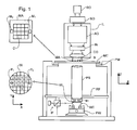
- Figure 1 schematically depicts an embodiment of lithographic apparatus suitable for use with the invention.
- the apparatus comprises:
- the illumination system IL may include various types of optical components, such as refractive, reflective, magnetic, electromagnetic, electrostatic or other types of optical components, or any combination thereof, for directing, shaping, or controlling radiation.
- optical components such as refractive, reflective, magnetic, electromagnetic, electrostatic or other types of optical components, or any combination thereof, for directing, shaping, or controlling radiation.
- the support structure MT supports, i.e. bears the weight of, the patterning device MA. It holds the patterning device MA in a manner that depends on the orientation of the patterning device MA, the design of the lithographic apparatus, and other conditions, such as for example whether or not the patterning device MA is held in a vacuum environment.
- the support structure MT can use mechanical, vacuum, electrostatic or other clamping techniques to hold the patterning device MA.
- the support structure MT may be a frame or a table, for example, which may be fixed or movable as required.
- the support structure MT may ensure that the patterning device MA is at a desired position, for example with respect to the projection system PS. Any use of the terms "reticle” or “mask” herein may be considered synonymous with the more general term "patterning device.”
- patterning device used herein should be broadly interpreted as referring to any device that can be used to impart a radiation beam with a pattern in its cross-section such as to create a pattern in a target portion of the substrate. It should be noted that the pattern imparted to the radiation beam may not exactly correspond to the desired pattern in the target portion of the substrate, for example if the pattern includes phase-shifting features or so called assist features. Generally, the pattern imparted to the radiation beam will correspond to a particular functional layer in a device being created in the target portion, such as an integrated circuit.
- the patterning device may be transmissive or reflective.
- Examples of patterning devices include masks, programmable mirror arrays, and programmable LCD panels.
- Masks are well known in lithography, and include mask types such as binary, alternating phase-shift, and attenuated phase-shift, as well as various hybrid mask types.
- An example of a programmable mirror array employs a matrix arrangement of small mirrors, each of which can be individually tilted so as to reflect an incoming radiation beam in different directions. The tilted mirrors impart a pattern in a radiation beam which is reflected by the mirror matrix.
- projection system used herein should be broadly interpreted as encompassing any type of projection system, including refractive, reflective, catadioptric, magnetic, electromagnetic and electrostatic optical systems, or any combination thereof, as appropriate for the exposure radiation being used, or for other factors such as the use of an immersion liquid or the use of a vacuum. Any use of the term “projection lens” herein may be considered as synonymous with the more general term “projection system”.
- the apparatus is of a transmissive type (e.g. employing a transmissive mask).
- the apparatus may be of a reflective type (e.g. employing a programmable mirror array of a type as referred to above, or employing a reflective mask).
- the lithographic apparatus may be of a type having two (dual stage) or more substrate tables (and/or two or more mask tables). In such "multiple stage” machines the additional tables may be used in parallel, or preparatory steps may be carried out on one or more tables while one or more other tables are being used for exposure.
- the illuminator IL receives a radiation beam from a radiation source SO.
- the source SO and the lithographic apparatus may be separate entities, for example when the source SO is an excimer laser. In such cases, the source SO is not considered to form part of the lithographic apparatus and the radiation beam is passed from the source SO to the illuminator IL with the aid of a beam delivery system BD comprising, for example, suitable directing mirrors and/or a beam expander.
- the source SO may be an integral part of the lithographic apparatus, for example when the source SO is a mercury lamp.
- the source SO and the illuminator IL, together with the beam delivery system BD if required, may be referred to as a radiation system.
- the illuminator IL may comprise an adjuster AD for adjusting the angular intensity distribution of the radiation beam.
- an adjuster AD for adjusting the angular intensity distribution of the radiation beam.
- the illuminator IL may comprise various other components, such as an integrator IN and a condenser CO.
- the illuminator IL may be used to condition the radiation beam, to have a desired uniformity and intensity distribution in its cross-section.
- the radiation beam B is incident on the patterning device (e.g., mask MA), which is held on the support structure (e.g., mask table MT), and is patterned by the patterning device MA. Having traversed the mask MA, the radiation beam B passes through the projection system PS, which focuses the beam onto a target portion C of the substrate W.
- the substrate table WT can be moved accurately, e.g. so as to position different target portions C in the path of the radiation beam B.
- the first positioner PM and another position sensor can be used to accurately position the mask MA with respect to the path of the radiation beam B, e.g. after mechanical retrieval from a mask library, or during a scan.
- movement of the mask table MT may be realized with the aid of a long-stroke module (coarse positioning) and a short-stroke module (fine positioning), which form part of the first positioner PM.
- movement of the substrate table WT may be realized using a long-stroke module and a short-stroke module, which form part of the second positioner PW.
- the mask table MT may be connected to a short-stroke actuator only, or may be fixed.
- Mask MA and substrate W may be aligned using mask alignment marks M1, M2 and substrate alignment marks P1, P2.
- the substrate alignment marks as illustrated occupy dedicated target portions, they may be located in spaces between target portions (these are known as scribe-lane alignment marks).
- the mask alignment marks may be located between the dies.
- the depicted apparatus could be used in at least one of the following modes:
- FIG. 4 An immersion lithography solution with a localized liquid supply system is shown in Figure 4 .
- Liquid is supplied by two groove inlets IN on either side of the projection system PS and is removed by a plurality of discrete outlets OUT arranged radially outwardly of the inlets IN.
- the inlets IN and OUT can be arranged in a plate with a hole in its centre and through which the projection is project.
- Liquid is supplied by one groove inlet IN on one side of the projection system PS and removed by a plurality of discrete outlets OUT on the other side of the projection system PS, causing a flow of a thin film of liquid between the projection system PS and the projection system PS and removed by a plurality of discrete outlets OUT on the other side of the projection system PS, causing a flow of a thin film of liquid between the projection system PS and the substrate W.
- the choice of which combination of inlet IN and outlets OUT to use can depend on the direction of movement of the substrate W (the other combination of inlet IN and outlets OUT being inactive).
- FIG. 5 Another immersion lithography solution with a localized liquid supply system solution which has been proposed is to provide the liquid supply system with a seal member (or so-called immersion hood) which extends along at least a part of a boundary of the space between the final element of the projection system and the substrate table.
- a seal member or so-called immersion hood
- the seal member is substantially stationary relative to the projection system PS in the XY plane though there may be some relative movement in the Z direction (in the direction of the optical axis).
- a seal is formed between the seal member and the surface of the substrate W.
- a seal member 12 forms a contactless seal to the substrate W around the image field of the projection system PS so that liquid is confined to fill a reservoir or an immersion space 11 between the substrate surface and the final element of the projection system PS.
- the reservoir 11 is formed by a seal member 12 positioned below and surrounding the final element of the projection system PS. Liquid is brought into the space 11 below the projection system PS and within the seal member 12.
- the seal member 12 extends a little above the final element of the projection system PS and the liquid rises above the final element so that a buffer of liquid is provided.
- the seal member 12 has an inner periphery that at the upper end, in an embodiment, closely conforms to the shape of the projection system PS or the final element thereof and may, e.g., be round. At the bottom, the inner periphery closely conforms to the shape of the image field, e.g., rectangular though this need not be the case.
- the liquid is confined in the reservoir 11 by a gas seal 16 between the bottom of the seal member 12 and the surface of the substrate W.
- the gas seal 16 is formed by gas, e.g. air or synthetic air but, in an embodiment, N 2 or another inert gas, provided under pressure via inlet 15 to the gap between seal member 12 and substrate W and extracted via first outlet 14.
- the overpressure on the gas inlet 15, vacuum level on the first outlet 14 and geometry of the gap are arranged so that there is a high-velocity gas flow inwards that confines the liquid.
- the substrate W is moved under the projection system PS and the liquid supply system.
- the relative movement of the table may be to enable an edge of the substrate W is to be imaged or a sensor on the substrate table WT to be imaged for sensing purposes or for substrate swap.
- Substrate swap is removal and replacement of the substrate W from the substrate table WT between exposures of different substrates.
- liquid may be kept within the fluid confinement structure 12. This is achieved by moving the fluid confinement structure 12 relative to the substrate table WT, or vice versa, so that the fluid confinement structure 12 is placed over a surface of the substrate table WT away from the substrate W.
- a surface is a shutter member.
- Immersion liquid may be retained in the fluid confinement structure 12 by operating the gas seal 16 or by clamping the surface of the shutter member to the undersurface of the fluid confinement structure 12.
- the clamping may be achieved by controlling the flow and/or pressure of fluid provided to the undersurface of the fluid confinement structure 12. For example, the pressure of gas supplied from the inlet 15 and/or the under pressure exerted from the first outlet 14 may be controlled.
- the surface of substrate table WT over which the fluid confinement structure 12 is placed may be an integral part of the substrate table WT or it may be a detachable and or replaceable component of the substrate table WT. Such a detachable component may be referred to as closing disc or a dummy substrate.
- the detachable or separable component may be a separate stage. In a dual or multi stage arrangement the entire substrate table WT is replaced during substrate exchange. In such an arrangement the detachable component may be transferred between substrate tables.
- the shutter member may be an intermediate table that may be moved adjacent to the substrate table WT prior to substrate exchange. The fluid confinement structure 12 may then be moved onto the intermediate table, or vice versa during substrate exchange.
- the shutter member may be a moveable component of the substrate table WT, such as a retractable bridge, which may be positioned between the stages during substrate exchange. The surface of the shutter member may be moved under the fluid confinement structure 12, or vice versa, during substrate exchange.
- a drain may be provided around the edge of a substrate W, such as in the gap.
- a drain may be located around another object on the substrate table WT.
- Such an object may include, but is not limited to, one or more sensors and/or a shutter member used to maintain liquid in the liquid supply system by being attached to the bottom of the liquid supply system during, for example, substrate swap.
- any reference to the substrate W should be considered to be synonymous with any such other object, including a sensor or shutter member, such as a closing plate.
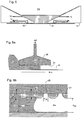
- FIGS 6a and 6b illustrate a liquid removal device 20 which may be used in immersion systems to remove liquid between the immersion hood IH and the substrate W.
- the liquid removal device 20 comprises a chamber which is maintained at a slight underpressure p c and is filled with the immersion liquid.
- the lower surface of the chamber is formed of a porous member 21 having a plurality of small holes, e.g. of diameter d hole in the range of 5 to 50 ⁇ m, and is maintained at a height h gap less than 1 mm, desirably in the range of 50 to 300 ⁇ m above a surface from which liquid is to be removed, e.g. the surface of a substrate W.
- the porous member 21 may be a perforated plate or any other suitable structure that is configured to allow the liquid to pass there through.
- porous member 21 is at least slightly hydrophilic, i.e. having a contact angle of less than 90° to the immersion liquid, e.g. water.
- Such liquid removal devices can be incorporated into many types of seal member 12 of an immersion hood IH.
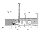
- Figure 6c is a cross-sectional view of one side of the seal member 12, which forms a ring (as used herein, a ring may be circular, rectangular or any other shape and it may be continuous or discontinuous) at least partially around the exposure field of the projection system PS (not shown in Figure 6c ).
- the liquid removal device is formed by a ring-shaped chamber 31 near the innermost edge of the underside of the seal member 12.
- the lower surface of the chamber 31 is formed by a porous member 21 such as the porous member described above.
- Ring-shaped chamber 31 is connected to a suitable pump or pumps to remove liquid from the chamber 31 and maintain the desired underpressure. In use, the chamber 31 is full of liquid but is shown empty here for clarity.
- Outward of the ring-shaped chamber 31 may be a gas extraction ring 32 and a gas supply ring 33.
- the gas supply ring 33 may have a narrow slit in its lower part and is supplied with gas, e.g. air, artificial air or flushing gas, at a pressure such that the gas escaping out of the slit forms a gas knife 34.
- the gas forming the gas knife 34 is extracted by a suitable vacuum pumps connected to the gas extraction ring 32 so that the resulting gas flow drives any residual liquid inwardly where it can be removed by the liquid removal device and/or the vacuum pumps, which should be able to tolerate vapor of the immersion liquid and/or small liquid droplets.
- the liquid removal device since the majority of the liquid is removed by the liquid removal device, the small amount of liquid removed via the vacuum system does not cause unstable flows which may lead to vibration.
- chamber 31, gas extraction ring 32, gas supply ring 33 and other rings are described as rings herein, it is not necessary that they surround the exposure field or be complete. They may be continuous or discontinuous. In an embodiment, such inlet(s) and outlet(s) may simply be any annular shape such as circular, rectangular or other type of elements extending partially along one or more sides of the exposure field, such as for example, shown in Figures 2, 3 and 4 .
- Single phase extractors can also be used in two phase mode in which both liquid and gas are extracted (say 50% gas, 50% liquid).
- the term single phase extractor is not intended herein to be interpreted only as an extractor which extracts one phase, but more generally as an extractor which incorporates a porous member through which gas and/or liquid is/are extracted.
- the gas knife i.e. the gas supply ring 33
- the gas supply ring 33 may be absent.
- the above mentioned single phase extractor can be used in liquid supply systems which supply liquid to only a localized area of the top surface of the substrate. Furthermore, such extractors can also be used in other types of immersion apparatus. Also the extractors can be used for immersion liquids other than water. The extractors can also be used in so-called "leaky seal" liquid supply systems. In such liquid supply systems liquid is provided to the space between the final element of the projection system and the substrate. That liquid is allowed to leak from that space radially outwardly. For example, an immersion hood or fluid confinement system or liquid supply system is used which does not form a seal between itself and the top surface of the substrate or substrate table, as the case may be.
- the immersion liquid may only be retrieved radially outwardly of the substrate in a "leaky seal" apparatus.
- the comments made in relation to a single phase extractor may apply to other types of extractor, for example, for example an extractor without a porous member.
- Such an extractor may be used as a two phase extractor for extracting both liquid and gas.
- the present invention will be described in relation to a lithographic apparatus having an immersion system with a liquid handling system and drain as described in the aforementioned figures. However, it will be apparent that the present invention can be applied to any sort immersion apparatus.
- the present invention is applicable to any immersion lithographic apparatus in which defectivity is a problem which is reduced optimally and desirably minimized.
- the systems and components described in the earlier passages of the description are thus example systems and components.
- the invention may apply to other features of the immersion system which include, but is not limited to, cleaning systems and cleaning tools for in-line and off-line implementations; the water supply and water retrieval systems such as an ultra pure water supply system; and the gas supply and removal systems (e.g. a vacuum pump).
- the present invention is applicable to any immersion lithographic apparatus in which defectivity is a problem which it is desired to alleviate and so minimize.
- the present invention will be described below in relation to an immersion system optimized for supplying an immersion liquid. However, the present invention is equally applicable for use with an immersion system that uses a fluid supply system supplying a fluid other than a liquid as the immersion medium.
- immersion lithographic systems contamination, especially organic contamination, may build up. This influences the number of defects in a pattern formed on a substrate.
- the functionality of immersion lithographic systems such as meniscus stability of the single phase extractor, may be influenced by contaminant aggregation.
- a variety of different methods are being developed to clean the immersion systems to remove the contamination with a minimal down time. Some of these techniques, for example, require cleaning chemicals that have a number of drawbacks which may impact on damage to the immersion system, tool design, safety, cleaning time (for example because of rinsing).
- Cleaning using a flow of radicals generated by a plasma radical source may remove most, if not substantially all, organic materials on the surface being cleaned. Such cleaning may be referred to as plasma cleaning or atmospheric plasma cleaning. However, the cleaning is not selective. Furthermore, immersion systems have many sensitive components. The use of plasma technology to clean an immersion system, especially in-line, for example, installed within a lithographic apparatus so that cleaning can take place without removing one or more components, has previously been considered unfavorable because of all the potential damage risks.
- atmospheric plasma techniques may be used to clean a contaminated surface.
- conditions are carefully selected, for example, using at least one damage limitation measure it has been found that atmospheric plasma cleaning may be used successfully in a complex immersion lithographic environment.
- the plasma may generate an activated species that may be directed in a gas flow directed towards a contaminated surface.
- the activated species is a short living radical that is active over a short distance.
- the plasma may be used to generate radicals in a plasma region.
- a flow of gas may be provided through a plasma region to generate the radicals that may be used for cleaning.
- Three dimensional surfaces may be readily cleaned, the activated species flowing over the surface to be cleaned. Surfaces suitable for cleaning include the immersion system and a substrate edge before it is placed on the substrate table. Rinsing may be unnecessary because, apart from the species generated in the plasma, chemicals are not used.
- a reductive plasma or an oxidative plasma depending on the surface desired to be cleaned, noting that a reductive plasma (i.e. unlike an oxidative plasma) generates radicals which may not damage metals or etch glass; avoiding surfaces sensitive to the radicals; preventing the radicals from accessing some surfaces by using a protective air flow and/or providing a physical barrier to prevent the radicals from reaching sensitive surfaces; using radio frequency generated plasmas, which may result in lower temperature gas flows than other forms of generating a plasma; or supplying a gas flow from which ions have been removed and/or which only provides a flow of radicals.
- a flow of gas, at a temperature of below 60 degrees Celsius, onto a surface may remove 100 to 200 nm of contaminants per minute.
- temperature effects may be reduced by using short contact times on a surface or pulsing the plasma radical source.
- the cleaning technique may be a simple and fast method enabling mainly organic contamination to be removed, including from sensitive surfaces.
- the method may be used to remove resist like contamination and other types of contamination which may be difficult to remove (for example partly carbonized contamination).
- the cleaning technique may use radicals generated from oxygen (oxidative plasma) or hydrogen (reductive plasma) in an inert gas.
- the inert gas may be, for example, nitrogen or a nobel gas, such as neon, argon, xenon or helium.
- the inert gas may be mixed with an active gas.
- the active gas may be hydrogen or oxygen.
- the inert gas may be mixed with, or may be, air.
- the gas including a combination of an inert gas and an active gas may be passed through a plasma generating region in which radicals may be formed from the active gas.
- the plasma generating region may be part of the plasma radical source. It will be appreciated that the gas source providing the flow of gas to the plasma generating region may be provided at some distance from the plasma generating region.
- the plasma generating region may include a high temperature element located within the flow of gas.
- the temperature of such a high temperature element should be sufficient to cause thermal dissociation in order to create radicals.
- Such an arrangement may, in particular, be used with a flow of air or purified air in order to provide oxygen radicals for cleaning.
- the plasma generating region may include at least one of an RF coil, a pair of AC or DC discharge electrodes and a microwave or RF cavity that generates a region of plasma within the flow of gas provided from the gas source. Radicals may be formed in the plasma region.
- the concentration of the active gas may be low, for example it may be between approximately 0.5% and approximately 2% of the gas supplied by the gas source. In a particular arrangement, the active gas may be approximately 1% of the gas supplied by the gas source.
- a conduit supplies radicals from the plasma radical source to the surface to be cleaned.
- the plasma radical source and the conduit may be configured such that substantially no ions are provided from the conduit to the surface to be cleaned. In particular, this may be achieved by ensuring that the conduit is sufficiently long that the majority, if not all, of the ions formed in the plasma generating region collide with a surface of the conduit or with other plasma and/or gas species and are therefore removed. Such an arrangement may be desirable because the ions may cause damage to the surface to be cleaned.
- the cleaning apparatus may be arranged to provide a flow of radicals to the surface to be cleaned without including a significant number of ions within the flow.
- the plasma generating region may be located between approximately 1mm and approximately 30mm from the surface to be cleaned.
- the outlet of the conduit may be as close as 0.1mm, for example, from the surface to be cleaned. However a greater distance may facilitate a cleaning process, for example, if the surface to be cleaned has a 3D shape and the conduit outlet is to be scanned above the surface.
- the arrangement may be selected to provide a sufficient length of conduit for the ions to be removed from the flow or reduced to a desirable level. At the same time, the number of radicals within the flow may not be reduced to below a level at which the cleaning ceases to be sufficiently effective.
- the desired distance between the plasma radical source and the surface to be cleaned may depend on the design of the conduit, for example the design of the conduit outlet.
- a reductive plasma may be preferred to an oxidative plasma.
- a reductive plasma does not cause oxidative damage.
- a suitable reductive plasma comprises hydrogen.
- the temperature of the gas flow when it is applied to the surface to be cleaned may be between 50-100° C. If an RF source is used to generate a plasma, the gas flow applied to the surface may, for example, be approximately 60° C. If a thermal source is used to generate a plasma, the temperature of the gas flow applied to the surface may be approximately 100° C.
- the use of an RF source may be beneficial because the temperature of the gas flow applied to the surface to be cleaned maybe lower, reducing the heating on the surface. This may be beneficial because heat loads on a sensitive surface within an immersion lithographic apparatus may result in damage.
- the cleaning process is completed, if there has been significant heating of any components, it may be necessary to wait until the components have cooled before lithography processing can be resumed. Accordingly, heating of components within the lithographic apparatus may result in additional loss of exposure processing time beyond the time required to perform the cleaning process.
- the temperature of the gas flow provided to the surface to be cleaned may be higher if a thermal source is used to generate a plasma than if an RF source is used.
- the gas flow in that case may include a larger number of radicals than if an RF source is used. Accordingly, the time for which the gas flow must be provided to a surface in order to remove a required amount of contaminants may be lower than the time that would be required for a radical cleaning process using an RF source. Accordingly, by applying a higher temperature gas flow for a smaller amount of time, the total heat load applied to the surface during the cleaning process may be the same or smaller.
- the amount of time that the gas flow is applied to the surface to be cleaned should be minimized.
- the surface to be cleaned may not be warmed up dramatically.
- the heat load may be minimal, minimizing the possible damage that could be caused to the surface.
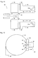
- Figure 15 schematically depicts a source of radicals that may be used as part of a cleaning apparatus of the invention.
- a gas source 100 provides a flow of gas that passes through a plasma generating region 101 in which radicals may be formed and is directed by a conduit 102 onto a surface 103 to be cleaned.
- the plasma generating region 101 may include at least one of a high temperature element located within the flow of gas, an RF coil, a pair of AC or DC discharge electrodes and a microwave or RF cavity.
- the conduit outlet may be located between approximately 1 mm and approximately 30 mm from said surface to be cleaned. More desirably, the distance between the surface and the conduit outlet may be in the range of approximately 10 mm to 20 mm.
- the cleaning apparatus may, in particular, be a so-called atmospheric plasma cleaner. It may also be referred to as a plasma cleaner.
- the flow of gas from the plasma cleaner including the radicals which are to be used for the cleaning process, is output into a space at substantially atmospheric pressure.
- the space does not need to be evacuated.
- the cleaning apparatus may be used with minimal preparation time because, for example, it is not necessary to evacuate a space before the cleaning process can commence.
- the gas supply providing a flow of gas to the plasma cleaner should provide the gas at a higher pressure than the pressure of the space in which the plasma cleaner is operating.
- the present invention may be a cleaning apparatus configured to clean a substrate or component of an immersion lithographic apparatus.
- the immersion lithographic apparatus may comprise a substrate table and a fluid confinement system.
- the substrate table may support a substrate.
- the fluid confinement system may confine immersion fluid between a projection system and substrate table, a substrate or both.
- the cleaning apparatus may comprise: a plasma radical source, a conduit and a radical confinement system.
- the plasma radical source provides a flow of radicals.
- the plasma radical source may be configured to supply a source of reducing radicals or oxidizing radicals.
- the plasma radical source may be configured to remove ions from the flow of radicals. Desirably, radicals are the only active component supplied by the radical flow.
- the conduit is configured to supply radicals from the plasma radical source to the surface to be cleaned.
- the radical confinement system is configured to direct the radicals to clean a localized portion of said surface.
- the radicals are directed at a localized portion of a surface to be cleaned, the radicals are directed at a single portion for a short duration of time. This is to enable different portions of the surface to be cleaned. Thus the portions may be changed so that substantially the whole surface can be cleaned. A short contact time is desirable because the surface to be cleaned does not warm up significantly, minimizing the risk of damage to the surface.
- the radical confinement system may comprise a barrier member. Accordingly, the flow of radicals to sensitive components may be prevented or restricted.
- the radical confinement system may be configured to provide a flow of gas to the localized portion of the surface, for example away from sensitive components.
- the radical confinement system may be configured to provide the flow of gas so as to limit the radicals substantially to the same side of the barrier member as said localized portion of said surface.
- the barrier member may be a radical confinement chamber within which an outlet of said conduit is located. Accordingly, the radicals may be contained within the chamber, preventing or reducing their flow to sensitive components that may be located outside the chamber.
- the radical confinement chamber may comprise an outlet connected to an under pressure source. Accordingly, the pressure within the radical confinement chamber may be lower than the surrounding region of the lithographic apparatus. At a gap that may exist between an edge of the radical confinement chamber and the surface to be cleaned, gas will tend to flow into the radical confinement chamber. The flow of any radicals from within the radical confinement chamber to outside of the radical confinement chamber where sensitive components of the lithographic apparatus may be located, may be reduced or prevented.
- the radical confinement system may be specifically configured to form a gas flow to direct the radicals.
- the radical confinement system may include a gas outlet and a gas exhaust.
- the radical confinement system may be arranged such that the gas outlet provides a flow of gas towards a portion of the surface to be cleaned on which the flow of radicals from the conduit is directed.
- the flow of gas is directed so as to prevent the flow of radicals from the conduit flowing towards a different part of the surface that may, for example, include sensitive components.
- the gas exhaust may be arranged to extract gas, for example gas flowing from the conduit of the cleaning apparatus after it has been directed towards the surface to be cleaned and/or gas provided by the gas outlet of the radical confinement system. It will be appreciated, however, that a dedicated gas exhaust may not be required.
- the following description refers to exemplary embodiments of a plasma cleaner 42 or a cleaning apparatus for a surface of the immersion system.
- the specific embodiments described relate to plasma cleaners for a fluid confinement structure 12 (also known as an immersion hood) and a substrate table WT. Each of them may embody a cleaning apparatus previously described.
- the plasma cleaner 42 may have a volume of less than a litre, more desirably, less than 0.5 litres, enabling it to be readily fitted to a lithographic apparatus.
- the plasma cleaner 42 may be used in off-line embodiments or in-line embodiments, may be used to clean a surface within a lithographic apparatus without removing one or more components of the lithographic apparatus and/or without suspending the use of the lithographic apparatus for exposures for a significant amount of time. Alternatively or additionally, it may be used to perform cleaning processes while the use of the lithographic apparatus is suspended.
- the plasma cleaner 42 may be mounted under the fluid confinement structure 12 to clean a surface of the liquid confmement structure 12 such as its undersurface 44, as shown in Figure 7 . This may be an off-line embodiment. In an in-line embodiment, the plasma cleaner 42 may be located in a sensor recess or designated station located in the substrate table WT, as shown in Figure 8 .
- Figure 9 shows a rotatable plasma cleaner 42 for cleaning the undersurface 44 of the fluid confinement structure 12.
- the plasma cleaner 43 may be mounted to an immersion lithographic apparatus to clean the surface of a substrate table WT, as shown in Figure 10 .
- This may be an in-line or an off-line implementation.
- the plasma cleaner 42 may be integrated into a fluid confinement structure 12, so that for an outlet 50 of a plasma cleaner conduit 46 may be directed to a localized surface of the substrate table WT.
- a cleaning apparatus may be installed in an immersion lithographic apparatus.
- Such an apparatus may in particular comprise a projection system, an immersion fluid confinement structure and a substrate table for supporting a substrate.
- the projection system may be configured to impart a patterned beam onto a substrate.
- the immersion fluid confinement structure may be configured to confine an immersion fluid between the projection system and the substrate or a substrate table.
- the cleaning apparatus may be have the features of a plasma cleaner as previously described and may be arranged to clean a localized portion of a surface of the fluid confinement structure.
- the cleaning apparatus may be an integral part of the immersion lithographic apparatus.
- the cleaning operation may occur while the fluid confinement structure is installed within the immersion lithographic apparatus.
- the radical confinement system of the cleaning apparatus may, in particular, be configured to prevent radicals from being directed onto an element of the projection system. This may be important because the elements of the projection system may be susceptible to damage by a plasma cleaner and any such damage may degrade the performance of the projection system.
- the substrate table may be configured such that the substrate table can be removed from the region adjacent the fluid confinement structure and the projection system.
- the cleaning apparatus may be operable to clean said localized portion of a surface of the fluid confinement structure.
- the plasma cleaner may be mounted to an actuator system.
- the plasma cleaner may be arranged such that it can advance to the surface to be cleaned of the fluid confinement structure.
- the plasma cleaner may be moved towards the fluid confinement structure once the substrate table is removed from the region adjacent the fluid confinement structure.
- the cleaning apparatus may be moved relative to the fluid confmement structure by movement of the substrate table.
- the cleaning apparatus may, for example, be installed within the substrate table in a location such that, when the substrate table is supporting a substrate, the substrate is located on top of the cleaning apparatus. Accordingly, when the substrate table is supporting a substrate the cleaning apparatus does not interfere with the normal operation of the immersion lithographic apparatus. However, when the substrate table is not supporting a substrate, the substrate table may be moved as required to position the cleaning apparatus as necessary to clean a desired portion of a surface of the fluid confinement structure.
- the cleaning apparatus may be located in the substrate table away from the location of the substrate table that supports the substrate. Such a location may be an opening in the substrate table for a sensor.
- the immersion fluid confinement structure may surround an element of the projection system.
- the cleaning apparatus may be configured to clean a band on a surface of the immersion fluid confinement structure that may surround said element of the projection system.
- Said band may be an annular region of the surface of the immersion fluid confinement structure.
- the outlet of the conduit supplying said radicals may be configured to conform to the shape of said band to be cleaned.
- One or more plasma radical sources may be arranged to provide radicals to said conduit.
- Figure 7 depicts an embodiment of a cleaning apparatus 42 for cleaning a surface of a fluid confinement structure 12 which may, in particular, be off-line.
- a gas flow from a gas source 45 may pass through a plasma radical source 46.
- the plasma radical source 46 may be located in a plasma head in which a region of plasma is generated as discussed above.
- the gas flow may entrain radicals generated by the plasma radical source 46.
- the gas flow may pass through a conduit 48.
- the conduit 48 may direct the gas flow to a localized under surface 44 of the fluid confinement structure 12 being cleaned. In this way at least one of the gas knife extractor, gas knife and single phase extractor may be cleaned.
- the conduit may be configured to be sufficiently long so as to remove ions from the gas flow before the gas flow is used for cleaning. If ions are present in the gas flow, the ions may damage the surface being cleaned.
- the conduit 48 may have an outlet 50 by which the gas flow 49 is directed to the localized surface.
- the outlet 50 may be positioned 5 to 20 mm from the surface being cleaned.
- the outlet 50 may be located in a radical confinement system 40.
- the radical confinement system 40 may comprise a chamber which may enclose the environment in which the cleaning apparatus operates. One or more edges 52 of the radical confinement system 40 may act as a barrier member to restrict the flow of the plasma generated radicals over the surface of the fluid confinement structure 12 by physically blocking the flow.
- a gas flow 54 between one or more of the edges 52 and the fluid confinement structure 12 may be used to restrict the radicals to a localized surface of the fluid confinement structure 12.
- the gas flow 54 may limit the radicals substantially to the same side of the barrier member as said localized portion of said surface.
- the chamber may comprise one or more outlets 56 connected to an under pressure source to extract gas from the chamber and to control the flow of the radicals.
- the provision of the under pressure source, extracting gas from the chamber may be sufficient to lower the pressure within the chamber below the pressure in the remainder of the immersion lithographic apparatus. Accordingly, the pressure difference established by the under pressure source connected to the outlet 56 may establish the gas flow 54 between the one or more edges 52 of the chamber and the fluid confinement structure 12. Alternatively or additionally, separate gas sources may be provided having appropriately placed outlets in order to establish the gas flow 54. Together these features act as an active lens cover. Any impact of active species on the final element of the projection system PS which may be adjacent the immersion confinement structure may thus be avoided. Additionally or alternatively, a passive, physical lens cover may also be used.
- the cleaning apparatus 42 may be mounted to the immersion system using the three connection points, which may be near the final element of the projection system PS.
- the substrate table WT is removed from the immersion lithographic apparatus first or, at least, moved away from the projection system.
- the cleaning apparatus 42 may, as described above, be arranged such that the outlet 50 of the conduit is annular, e.g. ring-shaped, such that it may simultaneously clean a band, for example an annular band, on the surface of the fluid confinement structure.
- a band for example an annular band
- the annular band may correspond to the location of a component of the fluid confinement structure, for example, porous member 21.
- the components of the cleaning apparatus 42 may be mounted to an actuator system or to the substrate table such that the outlet 50 of the conduit 48 may be moved to the required locations to clean at least a part of the surface of the fluid confinement structure 12.
- the outlet 50 of the conduit 48 may be relatively small. This may permit the use of a smaller plasma generating region but may require the cleaning apparatus 42 to be moved in order to clean all of the areas of the under surface 44 of the fluid confinement structure 12 that require cleaning.
- the actuator system and/or substrate table may be connected to a controller. Thus, the cleaning apparatus may be controlled to select the surface of the confinement structure to be cleaned.
- components of the cleaning apparatus 42 may be configured to rotate about an axis.
- the outlet 50 of the conduit 48 may be rotated through part of or a complete revolution of 360 degrees in order to provide cleaning to part of or substantially all of an annular band on the under surface 44, for example the surface of the porous member 21.
- the cleaning apparatus may be connected to a controller arranged to control the rotation of the cleaning apparatus. Thus, by operating the controller, the surface cleaned may be selected.
- the complete undersurface 44 of the fluid confinement structure 12 may be cleaned by any or all of the means discussed above.
- a reductive plasma may be used to generate the radicals so as to avoid oxidation of features such as the single phase extractor and coatings.
- the contact time may be limited to avoid damage caused by over-heating of some features.
- Such off-line atmospheric plasma cleaning may take a shorter duration than other known off-line cleaning techniques. Desirably, such off-line atmospheric plasma cleaning may be considered a rapid off-line method.
- Figure 8 depicts an embodiment of a cleaning apparatus 42 that may in particular be used for in-line cleaning of surfaces of the fluid confinement structure and/or components associated with it, such as surfaces of sensors.
- the embodiment shown has similar features as the embodiment shown in Figure 7 . Variants discussed above in relation to Figure 7 may be applied to the arrangement depicted in Figure 8 .
- the cleaning apparatus may be located in a portion of the substrate table WT, such as a cleaning station.
- the fluid confinement structure 12 may be moved relative to the substrate table WT so that it located above the conduit outlet 50.
- the cleaning apparatus 42 may have a radical confinement system 40 defined by a portion of the substrate table WT, but it might not have a chamber.
- the radical confinement system 40 may have a protective gas flow 54 to prevent the radicals from flowing over sensitive areas of the immersion system such as on the fluid confinement structure 12, or a lens of the projection system, as illustrated in the figure.
- the radical confinement system 40 may have one or more outlets 56 connected to an under pressure source in order to extract the radicals and to control the flow of the radicals.
- the under pressure source 56 may also be arranged such that it results in the space adjacent the cleaning apparatus 42 having a lower pressure than the space in the remainder of the immersion lithographic apparatus.
- the protective gas flow 54 results.
- the cleaning apparatus 42 may comprise one or more outlets 54a connected to a gas source that are specifically configured to provide the protective gas flow 54. Such an arrangement may be particularly beneficial if it is not possible to provide a chamber to limit the flow of radicals from the area to be cleaned.
- Figure 9 depicts an embodiment of part of a cleaning apparatus 42 according to the invention, located underneath a fluid confinement structure.
- the embodiment may be an off-line embodiment as shown in Figure 7 where the cleaning apparatus is fitted to the projection system PS, the fluid confinement structure 12 or both.
- the embodiment of Figure 9 may be implemented in an in-line embodiment in which the cleaning apparatus 42 may be in a cleaning station. Variants discussed above in relation to Figures 7 and 8 may be applied to the arrangement depicted in Figure 9 .
- the cleaning apparatus 42 may rotate, for example, about the optical axis of the projection system PS so that the undersurface 44 of the fluid confinement structure 12 and/or other components associated with it is cleaned.
- the cleaning apparatus 42 may have at least two radical confinement systems 40, each having a chamber in which may be located a conduit outlet 50.
- Each conduit outlet 50 may be associated with a separate plasma generating region 46, as depicted in Figure 9 .
- one or more conduit outlets 50 may be supplied with radicals by a common plasma generating region 46.
- the cleaning apparatus may comprise a single conduit outlet 50 and a single radical confinement system.
- the cleaning apparatus may be configured, for example, such that it can be rotated 360 degrees about the optical axis of the projection system.
- Each chamber may be connected to an under pressure source via one or more outlets 56. Thus, during cleaning, there is a gas flow into the chambers restricting the flow of the radicals to the localized surface being cleaned during cleaning.
- Figure 14 depicts an alternative arrangement for cleaning the under surface 44 of the fluid confinement structure 12.
- the cleaning apparatus 70 includes a main body 71 that is configured such that it may be mounted on the substrate table WT.
- the main body 71 may comprise a round plate having the same external diameter as a substrate such that the substrate table WT can support the main body 71 of the cleaning apparatus 70 in the same manner as it supports a substrate without any modification.
- the main body is formed from an insulating material and has one or more electrically conducting regions 77 located on the surface of the main body 71 that faces away from the fluid confinement structure 12.
- the at least one electrically conducting region 77 may be shaped to conform to the shape of a part of the fluid confinement structure 12 to be cleaned.
- the voltage required to establish the plasma generating region may depend on the thickness of the main body 71 and, in particular, the separation between the main body and the fluid confinement structure 12.
- the voltage required may, for example, be between about 50 and 300 V.
- a varying voltage should be used, such as an AC voltage having a sin wave form. However other voltage patterns may also be used.
- the voltage may be pulsed, providing time periods in which no voltage is provided. This may reduce heating.
- the cleaning apparatus 70 does not include its own gas source to be passed through the plasma generating region 72.
- the fluid confinement structure 12 of the immersion lithographic apparatus may be configured to provide the flow of gas which includes a mixture of inert gas and an active gas, as described above.
- the fluid confinement structure 12 may be configured such that, in a cleaning operation, it is drained of immersion liquid. Subsequently, the gas flow is provided by one or more components of the fluid confinement structure 12 and is supplied to the plasma generating region 72 in order to create the radicals.
- the fluid confinement structure components may be used during an exposure process to provide and/or control the immersion liquid.
- the fluid confinement structure 12 may be provided with separate conduits specifically for supplying and/or controlling the flow of gas during a cleaning operation.
- the flow of gas provided during the cleaning operation is configured such that it flows through the plasma generating region 72, the location of which may be defined by the location of the at least one electrically conducting region 77, resulting in the generation of radicals in the region in which cleaning is required.
- the flow of gas 73 provided to the plasma generating region 72 by the fluid confinement structure 12 may be configured such that the flow of gas also functions to confine the radicals that are generated.
- the flow of gas 73 may be arranged to flow from one or more gas inlets providing gas from the fluid confinement structure 12 to the space between the fluid confinement structure 12 and the main body 71 of the cleaning apparatus 70.
- the gas flow 73 may be extracted from one or more fluid outlets 75 in the fluid confinement structure 12.
- the gas flow 73 may be configured to flow away from the final element of the projection system PS. This ensures that the flow of radicals back to the projection system PS is prevented or significantly reduced when radicals are generated in the plasma generating region 72.
- a similar system may be used to prevent radicals flowing onto other sensitive components.
- Power may be supplied to the cleaning apparatus 70 by means of one or more electrodes mounted on the substrate table WT.
- one or more of the pins 76 of the substrate table, that are used to lift a substrate relative to the substrate table WT in order to enable the substrate to be removed from the substrate table WT may be connected to an electrical power source.
- one or more electrodes may be provided on the under surface of the main body 71 of the cleaning apparatus 70 and connected to the one or more electrically conducting regions 77.
- the one or more electrodes may be arranged such that the electrical contacts of the cleaning apparatus are in contact with the electrical contacts of the substrate table when the cleaning apparatus 70 is mounted to the substrate table WT. Actuation to achieve the arrangement may be achieved by operation of a controller.
- ions may be created in the plasma generating region 72.
- the damage that may be caused by any such ions may be reduced by controlling the energy of any such ions. This may be achieved, for example, by appropriate selection of the gas and the voltage provided between the at least one electrically conducting region 77 and the fluid confinement structure 12.
- An arrangement such as that depicted in Figure 14 in which the cleaning apparatus may be loaded to the lithographic apparatus for a cleaning process in the same manner as a substrate, may provide a convenient arrangement for rapid cleaning of the under surface 44 of the fluid confinement structure 12. Significant redesign of the immersion lithographic apparatus may not be required. Significant time required to re-configure an immersion lithographic apparatus for the performance of a cleaning process may be avoided. It should be appreciated that although the arrangement depicted in Figure 14 has been described above in the context of inline cleaning, for example cleaning at least a part of the lithographic apparatus without opening the lithographic apparatus, the arrangement may also be used for cleaning at least a part of the lithographic apparatus offline.
- Figures 16 and 17 depict arrangements that may be used to provide cleaning. These arrangements are similar to that which is discussed above in relation to Figure 14 and, accordingly, only the differences will be discussed. It should be appreciated that variations of the arrangements discussed above in relation to Figure 14 may also apply to the arrangements depicted in Figures 16 and 17 . In particular, the arrangements depicted in Figures 16 and 17 and described below may be used for either inline or offline cleaning.
- the arrangements depicted in Figures 16 and 17 provide a cleaning apparatus that has a main body 81 that is configured such that it may be mounted on the substrate table WT.
- the main body 81 may comprise a round plate having the same external diameter as a substrate such that the substrate table WT can support the main body 81 of the cleaning apparatus 80 in the same manner as it supports a substrate without any modification.
- the main body 81 is formed from an insulting material, for example Al 2 O 3 .
- the cleaning apparatus 81 includes a plurality of electrically conducting regions 82, 83.
- the cleaning apparatus 81 of the arrangements depicted in Figures 16 and 17 have two sets of one or more electrically conducting regions 82, 83, each set being connected to associated electrodes 85, 86.
- a voltage difference may be applied to the electrodes 85, 86, resulting in the establishment of a plasma 87 on the surface 84 of the main body 81 that faces the under surface 44 of the fluid confinement structure 12 and the projection system PS.
- any convenient arrangement for connecting the electrodes 85, 86 of the cleaning apparatus 80 to a voltage supply maybe used.
- the electrodes 85, 86 may be mounted onto the surface of the main body 81 that is supported by the substrate table WT. Accordingly, electrical contacts may be provided on the substrate table WT such that they come into contact with the electrodes 85, 86 in order to provide the voltage difference to the cleaning apparatus 80.
- the voltages applied to the cleaning apparatus 80 may be different to those provided to the cleaning apparatus 70 depicted in Figure 14 .
- a voltage difference of several kV may be used. This may enable the cleaning apparatus 80 to be used with a greater range of gases, namely may be used with gases having a higher ignition voltage.
- the cleaning apparatus 80 may have one or more first electrically conducting regions 82 on a side of the main body 81 that faces away from the fluid confinement structure 12 and/or the projection system PS. Accordingly, the one or more first electrically conducting regions are electrically isolated from the side of the main body 81 facing the fluid confinement structure 12 and/or projection system PS.
- the second set of electrically conducting regions 83 may be formed on the surface 84 of the main body 81 that faces the fluid confinement structure 12 and/or the projection system PS. Although not depicted in Figure 16 , the one or more first electrically conducting regions 82 may be covered by a layer of electrically insolating material.
- the cleaning apparatus 80 may be configured such that the first and second regions of electrically conducting material 82, 83 are embedded within the main body 81. Accordingly both sets of electrically conducting regions 82, 83 may be electrically isolated from the side of the main body 81 that faces the fluid confinement structure 12 and/or the projection system PS. Both arrangements depicted in Figures 16 and 17 may provide so-called Surface Dielectric Barrier Discharge (SDBD).
- SDBD Surface Dielectric Barrier Discharge
- a cleaning apparatus 80 such as that depicted in Figures 16 and 17 may be used to clean electrically non-conducting materials.
- the cleaning apparatus 80 depicted in Figures 16 and 17 may be used to clean the surface of a lens of the projection system PS, in particular the surface of the final element or lens of the projection system PS.
- the final element of an immersion lithographic apparatus may, in particular, require cleaning.
- the liquid may be a hydrocarbon fluid. When UV radiation passes through such a liquid, it may dissociate into carbon and gas. The carbon may coat the surface of the final element and may otherwise be difficult to remove.
- the cleaning apparatus 80 as depicted in Figures 16 and 17 may be advantageous because it may be possible to ensure localized cleaning of, for example, the lens. In particular, this may be possible because of one or more of the ability to confine the generated plasma 87 using a flow of gas, the ability to control the region in which the plasma 87 is formed by appropriate arrangement of the regions of electrically conducting material 82, 83 and the ability to control the position of the cleaning apparatus 80 relative to the lens, for example, using the substrate table WT.
- the surface 84 of the cleaning apparatus 80 may be brought within approximately 0.5 to 2mm from the surface of the lens. With such an arrangement, approximately 4 to 5 ⁇ m of contaminant may be removed per minute. Accordingly, it may be possible to clean a lens within a few minutes.
- Such a cleaning process may be provided periodically. For example. It may be provided regularly or simply when required. In an example, cleaning may be performed between approximately every 15 minutes and every hour.
- cleaning apparatus 80 depicted in Figures 16 and 17 may be particularly beneficial for cleaning electrically non-conducting components, such as a lens, it may also be used for cleaning other parts of a lithographic apparatus.
- the cleaning apparatus may have the features of the cleaning apparatus as previously described and may be arranged to clean a localized portion of a surface of the substrate table and/or components associated with the substrate table, such as surfaces of sensors.
- the actuator system may be arranged such that the cleaning apparatus can be moved between a first position and a second position. In the first position, the cleaning apparatus may clean a surface of the fluid confinement structure 12. In the second position, the cleaning apparatus may clean a surface of the substrate table.
- a dedicated cleaning apparatus may be provided for cleaning a surface of the substrate table.
- the cleaning apparatus may be configured to clean a localized portion of a surface of the substrate table while the substrate table is installed within the immersion lithographic apparatus.
- a radical confinement system of the cleaning apparatus may be configured so that a localized portion of the substrate table is cleaned without significant leakage of radicals to other parts of the apparatus.
- the substrate table may be removable from a region adjacent the fluid confinement structure and the projection system for a cleaning operation. When the substrate table is removed from said region, the cleaning apparatus may be operarable to clean said localized surface of the substrate table.
- At least an outlet of said conduit of the cleaning apparatus may be installed within the fluid confinement structure.
- the outlet may be located in a surface of the fluid confinement structure opposing the substrate table.
- Figure 10 depicts an embodiment the cleaning apparatus 42 cleaning a localized surface of substrate table WT.
- the cleaning apparatus 42 may have similar features as the embodiments as shown in Figures 7, 8 and 9 . Variants discussed above in relation to those arrangements may be applied to the cleaning apparatus for cleaning the substrate table.
- a gas source 45 may supply a gas flow.
- the gas flow may flow through a plasma generating region 46.
- the plasma generating region may be part of a plasma radical source 46 and may generate radicals which may be entrained by the gas flow.
- the gas flow is directed through a conduit 48 to the substrate table WT to clean the localized surface of the substrate table WT.
- the conduit 48 may have an outlet 50 through which the entraining gas is emitted.
- the cleaning apparatus 42 may comprise a radical confinement system 40 having a chamber which may restrict the flow of radicals to the localized surface being cleaned.
- a protective gas flow 54 between the substrate table WT and the radical confinement system 40, into the chamber.
- the chamber may have an outlet 56 connected to a source of under pressure which may, for example, establish the protective gas flow 54.
- This embodiment of the cleaning apparatus may be an off-line implementation in which the substrate table WT is removed from the lithographic apparatus.
- the cleaning apparatus 40 is then fitted to the substrate table WT to clean the substrate table surface.
- the cleaning apparatus WT may be integral to the fluid confinement structure, so that the conduit outlet 50 may be located in the undersurface of the fluid confinement structure.
- a plasma cleaner to clean a surface of a substrate may encounter a problem.
- Substrates have an organic coating, such as a resist.
- Known plasma cleaners do not direct the plasma generated radicals to a specific location as the gas flow from the plasma cleaner tends to broaden and spread to flow across the surface being cleaned. Thus there is a risk that the radicals will clean the substrate surface and remove previously created features on the substrate surface.
- the characteristics of as yet unexposed layers of resist may change if exposed to, for example, the radicals. This may have adverse effects on the imaging process or subsequent processing. It has been found that this problem may be solved by directing the radicals only to parts of substrate surface on which features have not been formed.
- a substrate cleaned by this technique will have an edge with improved defect count density (i.e. defectivity), namely a reduction in defect count density, without the need to have stringent specifications for substrates which are difficult to monitor.
- a plasma substrate cleaner 42 may be integrated into an immersion lithographic apparatus, e.g. as part of the wafer handler system, may be part of a stand-alone cleaning apparatus, may be part of a substrate transport system in a wafer fabrication facility and/or may be part of a processing unit that at least one of applies resist to a substrate, heats a substrate, chills a substrate and develops resist on a substrate.
- the atmospheric plasma cleaner may be used to rapidly remove organic contamination from the bevel and apex area of the substrate W.
- the cleaning apparatus may have any of the aforementioned features of the cleansing apparatus previously described, for example for cleaning fluid confinement structures/systems and substrate tables.
- the cleaning apparatus may comprise a substrate rotator.
- the substrate rotator may be configured to rotate a substrate relative to said conduit.
- at least a part of the cleaning apparatus may be configured to rotate about the substrate.
- a radical confinement system may be configured to direct the radicals to a localized portion of the periphery of the substrate. So, by rotation of the substrate relative to said conduit, the complete perimeter of the substrate may be cleaned.
- the conduit may direct the radicals onto a portion of the edge of the substrate.
- the conduit may direct the radicals onto a peripheral portion of a major face of the substrate on which devices are to be formed.
- the radical confinement system may comprise a protective gas source configured to provide a gas-flow in opposition to a flow of radicals from said conduit along at least one major surface of the substrate to limit the extent to which the radicals pass onto said surface of the substrate.
- the radical confinement system may comprise a gas extractor.
- the gas extractor may be located between said conduit and said protective gas source.
- the gas extractor may be arranged to extract radicals from said conduit and gas-flow from said protective gas source.
- the cleaning apparatus may comprise a substrate holder configured to hold the substrate.
- the substrate rotator may be configured to rotate both the substrate holder and substrate relative to said conduit.
- the substrate holder may comprise a substrate mount configured to support the substrate.
- the substrate rotator may be configured to rotate the substrate relative to the substrate mount.
- the substrate rotator may be configured to support the substrate during cleaning.
- the substrate rotator may be configured such that, in one mode it is operable to rotate the substrate relative to the conduit.
- the substrate rotator may have at least one other mode in which it is operable move the substrate between at least two locations, for example it may include actuators to move the substrate between a cleaning location and a load/unload position.
- a lithographic apparatus may comprise a substrate handler and a substrate cleaner.
- the substrate hander may be configured to position a substrate on a substrate table for supporting the substrate during exposure.
- the substrate handler may be configured to rotate the substrate prior to positioning the substrate on the substrate table.
- the substrate cleaner may be configured to clean a localized portion of the substrate surface as the substrate rotates.
- the plasma cleaner may comprise a plasma radical source, a conduit and a radical confinement system similar to those discussed above.
- the plasma radical source may provide a flow of radicals.
- the conduit may be configured to supply radicals from the plasma radical source to the surface to be cleaned.
- the radical confinement system may direct the radicals to clean said portion.
- Figure 11 depicts a cross-section through an embodiment of a cleaning apparatus 42 for cleaning an edge 64 of a substrate W; and Figure 12 depicts the same cleaning apparatus and a substrate handler 55 in plan view.
- This embodiment of the cleaning apparatus has similar features to those shown in Figures 7 to 10 , including, but not limited to: a gas source 45, a plasma radical source 46, a conduit 48, a conduit outlet 50 and a radical confinement system 40. Variations discussed above in relation to those arrangements may also be applied to the apparatus depicted in Figures 11 and 12 as appropriate.
- the radical confinement system 40 comprises a substrate enclosure 58 enclosing the portion of the substrate W being cleaned.
- the substrate enclosure 58 may have an aperture 60 which may be in the form of a slit.
- the aperture 60 may restrict access of the gas flow entraining the radicals to the peripheral portion of the substrate W, including the edge 64 of the substrate W. Thus the edge region 64 of the substrate W may be cleaned.
- the enclosure 58 may be configured so that a protective gas flow 54 is directed towards the flow of radicals, parallel to a major surface of the substrate W.
- the protective gas flow 54 may be sufficient to restrict the radicals to the surface required to be cleaned.
- the protective gas flow 54 may, for example, be provided by gas conduits 54a within the substrate enclosure 58 that are connected to a gas supply.
- substantially perpendicular to a major surface of the substrate W may be one or more outlets 62 connected to an under pressure source.
- the under pressure may act to remove gas from the substrate enclosure 58, such as exhaust gasses, and draw in the gas entraining the radicals into the substrate enclosure 58.
- the under pressure may draw in gas to the space between the substrate enclosure 58 and the substrate W, providing the protective flow of gas 54.
- the substrate enclosure 58 may be adjustable, so that it can be accurately positioned relative to the substrate W surface and the conduit outlet 50 so that a sharp clearly defined portion of the substrate surface is cleaned. Adjusting the position of substrate enclosure 58 relative to the surface of the substrate W may ensure that there is no contact between the substrate W and the substrate enclosure 58, especially during rotation of the substrate W, minimizing the risk of damage to the substrate W and/or any features that have already been formed on the substrate W.
- adjusting the separation between the surface of the substrate W and the substrate enclosure 58 may be used to adjust the size of the gap between them, adjusting the flow rate of the protective gas flow 54. This may provide a further tool for adjusting the extent to which the radicals pass over the surface of the substrate W.
- the cleaner 42 may be held by a substrate rotator.
- the rotator may rotate, rotating the substrate W about its axis. Accordingly during cleaning, the complete periphery of the substrate W may be cleaned.
- the rotator may be configured to handle the substrate W to move the substrate between two locations, for example from the substrate stack to a substrate cleaning position, or from the cleaning position to the substrate table WT for exposure, or from the substrate table WT back to the substrate stack.
- Figure 13 depicts another view of the embodiment of part of a substrate W and a cleaning apparatus 42 configured to clean the surface of a substrate W.
- the figure shows the relative positions of the substrate W, substrate enclosure 58, opposing outlets 62 and the conduit outlet 50.
- This embodiment may be beneficial because the parts of the wafer to which the plasma generated radicals are not intended to be directed may be shielded and a plume of radicals in the gas flow may be confined or directed.
- the cleaning apparatus may also be used to remove contaminants from layers formed on substrates, such as, for example, protective layers or membranes formed on an edge seal on a substrate.
- Variations of the described embodiment may achieve the same outcome.
- the embodiment may be varied in a number of ways.
- the settings of the plasma source and/or the entraining gas flow i.e. the speed of the radicals emitted from conduit
- the conduit outlet or substrate enclosure aperture geometry may be altered (e.g. the aperture may have a shape other than a slit).
- the distance between the surfaces of the substrate and the substrate enclosure may be changed. Note, it may be desirable that substrate surface is as close as possible to the wafer surface (e.g. 100 ⁇ m). The distance between the wafer and the edge may be varied depending upon the specific conditions.
- the under pressure may be varied, as may the flow rate of the protective gas and the geometry and the configuration of the radical confinement system and substrate enclosure.
- the cleaning apparatus to clean a substrate edge, desirably, there may be no, or minimal, damage to structures on the wafer by uncontrolled radical activity.
- the technique may remove resist like contamination within a short time. Surfaces that could be damaged by oxidizing species may be treated with a radicals generated by a reducing plasma, for example with a hydrogen concentration of 1 % hydrogen.
- the cleaning does not use chemicals that may leave drying stains.
- the method is contactless, so that there may be no physical damage risk to three dimensional surfaces.
- a cleaning Apparatus for cleaning a substrate or component of an immersion lithographic apparatus comprising a substrate table for supporting a substrate and a fluid confinement system for confining immersion fluid between a projection system and substrate table and/or substrate, the cleaning apparatus comprising:
- the radical confinement system comprises a barrier member.
- the radical confinement system is configured to provide a flow of gas so as to limit the radicals substantially to the same side of the barrier member as said localized portion of said surface.
- the barrier member is a radical confinement chamber within which the outlet of said conduit is located.
- the radical confinement chamber comprises an outlet connected to an under pressure source.
- the plasma radical source is located between approximately 1 mm and approximately 30 mm from said surface to be cleaned.
- the radical confinement system is configured to form a gas-flow to direct the radicals.
- the plasma radical source is configured to supply a source of reducing radicals.
- the plasma radical source is configured to supply a source of oxidizing radicals.
- the plasma radical source comprises a gas source and a plasma generating region; and the plasma radical source is configured to supply gas from said gas source so as to pass through said plasma generating region to said conduit.
- the plasma generating region comprises a high temperature element located within the flow of gas, the temperature of the high temperature element being sufficient to cause thermal dissociation to create the radicals.
- the gas source provides a supply of purified air.
- the plasma generating region comprises at least one of an RF coil, a pair of AC or DC discharge electrodes and a microwave or RF cavity that generates a region of plasma within the flow of gas from the gas source, the radicals being formed in the plasma region.
- the gas source provides a mixture of an inert gas and an active gas; wherein the inert gas is at least one of nitrogen, helium, argon, neon and xenon; and the active gas is one of oxygen and hydrogen. Desirably, the active gas is between approximately 0.5% and approximately 2%, and preferably approximately 1% of the gas supplied by the gas source.
- the said plasma radical source and said conduit are configured such that substantially no ions are provided from the conduit.
- the cleaning apparatus further comprises a rotator, configured to rotate a substrate relative to said conduit; wherein the radical confinement system is configured to direct the radicals to a localized portion of the periphery of the substrate such that, by rotation of the substrate relative to said conduit, the complete perimeter of the substrate may be cleaned.
- a rotator configured to rotate a substrate relative to said conduit
- the radical confinement system is configured to direct the radicals to a localized portion of the periphery of the substrate such that, by rotation of the substrate relative to said conduit, the complete perimeter of the substrate may be cleaned.
- said conduit directs the radicals onto a portion of the edge of the substrate.
- said conduit directs the radicals onto a peripheral portion of a major face of the substrate on which devices are to be formed.
- said radical confinement system comprises a protective gas source configured to provide a gas-flow in opposition to a flow of radicals from said conduit along at least one major surface of the substrate to limit the extent to which the radicals pass onto said surface of the substrate.
- the radical confinement system comprises a gas extractor, located between said conduit and said protective gas source, and arranged to extract radicals from said conduit and gas-flow from said protective gas source.
- the cleaning apparatus further comprises a substrate holder, configured to hold the substrate; wherein the rotator is configured to rotate the substrate holder relative to said conduit.
- the cleaning apparatus further comprises a substrate mount, configured to support the substrate; wherein the rotator is configured to rotate the substrate relative to the substrate mount.
- the rotator is configured to support the substrate during cleaning.
- the rotator is configured such that, in one mode it is operable to rotate the substrate relative to the conduit and, it has at least one other mode in which it is operable move the substrate between locations.
- the cleaning apparatus is installed within one of a lithographic apparatus, a transport unit configured to transport a substrate, and a substrate processing unit configured to at least one of coat a substrate with a resist, bake a substrate, cool a substrate and develop a layer of resist on a substrate that has been exposed with a patterned beam of radiation.
- an immersion lithographic apparatus comprising:
- the cleaning apparatus is configured to clean said localized portion of a surface of the fluid confinement structure while the fluid confinement structure is installed within the immersion lithographic apparatus; and the radical confinement system of the cleaning apparatus is configured to prevent radicals from being directed onto an element of the projection system.
- the immersion lithographic apparatus comprises a substrate table, configured such that the substrate table is removable from the region adjacent the fluid confinement structure and the projection system; and, when the substrate table is removed from said region, the cleaning apparatus is operable to clean said localized portion of a surface of the fluid confinement structure.
- the immersion lithographic apparatus comprises a substrate table, wherein at least an outlet of said conduit of the cleaning apparatus is installed within the substrate table.
- said fluid confinement structure surrounds an element of the projection system and the cleaning apparatus is configured to clean a band on a surface of the fluid confinement structure that surrounds said element of the projection system.
- the outlet of the conduit supplying said radicals is configured to conform to the shape of said band to be cleaned.
- a plurality of plasma radical sources are arranged to provide radicals to said conduit.
- an immersion lithographic apparatus comprising:
- the cleaning apparatus is configured to clean said localized portion of a surface of the substrate table while the substrate table is installed within the immersion lithographic apparatus; and the radical confinement system of the cleaning apparatus is configured to clean a localized portion of the substrate table.
- the substrate table is removable from a region adjacent the fluid confinement structure and the projection system; and, when the substrate table is removed from said region, the cleaning apparatus is operarable to clean said localized surface of the substrate table.
- At least an outlet of said conduit of the cleaning apparatus is installed within the fluid confinement structure.
- an lithographic apparatus comprising:
- a cleaning apparatus for cleaning a surface of an immersion lithographic apparatus comprising a substrate table for supporting a substrate and a fluid confinement structure for confining immersion fluid between a projection system and a substrate table and/or a substrate, the cleaning apparatus comprising:
- said main body comprises at least one second electrically conducting region that is electrically isolated from said first electrically conducting region.
- said second electrically conducting region is formed on a surface of the main body that faces the fluid confinement structure when the main body is supported on the substrate table.
- said second electrically conducting region is formed such that it is electrically isolated by at least a part of said main body from a surface of the main body that faces the fluid confinement structure when the main body is supported on the substrate table.
- an immersion lithographic apparatus comprising:
- an immersion lithographic apparatus comprising:
- the fluid confinement structure is configured to be switchable between an exposing state, in which it confines immersion fluid between the projection system and the substrate and/or the substrate table, and a cleaning state, in which it provides a flow of gas between the fluid confinement structure and the substrate table; and the immersion lithographic apparatus is configured such that, when the substrate table supports said cleaning apparatus and the fluid confinement structure is switched to said cleaning state, the substrate table is positioned such that the flow of gas provided by the fluid confinement structure passes through a region adjacent the at least one electrically conducting region and the voltage supplied between said at least one electrically conducting region and the liquid confinement structure generates radicals in said region.
- the fluid confinement structure is configured to be connected to a gas supply to provide said flow of gas, wherein said gas is a mixture of an inert gas and an active gas.
- said inert gas is at least one of nitrogen, helium, argon, neon and xenon; and the active gas is one of oxygen and hydrogen.
- said gas is purified air.
- the substrate table comprises at least one electrode connected to the voltage supply and configured to contact a corresponding at least one electrode on the cleaning apparatus that is further connected to said at least one electrically conducting region.
- the fluid confinement structure is configured such that, when it is in the cleaning state, the flow of gas provided by the fluid confinement structure and that passes into the region adjacent the at least one electrically conducting region is flowing in a direction away from the projection system.
- a method for cleaning a substrate or component of an immersion lithographic apparatus comprising a substrate table for supporting a substrate and a fluid confinement structure for confining immersion fluid between a projection system and substrate table and/or substrate, the method comprising:
- a method for cleaning a surface of an immersion lithographic apparatus comprising a substrate table for supporting a substrate and a fluid confinement structure for confining immersion fluid between a projection system and a substrate table and/or a substrate, the method comprising:
- lithographic apparatus in the manufacture of ICs
- the lithographic apparatus described herein may have other applications, such as the manufacture of integrated optical systems, guidance and detection patterns for magnetic domain memories, flat-panel displays, liquid-crystal displays (LCDs), thin-film magnetic heads, etc.
- LCDs liquid-crystal displays
- any use of the terms “wafer” or “die” herein may be considered as synonymous with the more general terms “substrate” or "target portion”, respectively.
- the substrate referred to herein may be processed, before or after exposure, in for example a track (a tool that typically applies a layer of resist to a substrate and develops the exposed resist), a metrology tool and/or an inspection tool. Where applicable, the disclosure herein may be applied to such and other substrate processing tools. Further, the substrate may be processed more than once, for example in order to create a multi-layer IC, so that the term substrate used herein may also refer to a substrate that already contains multiple processed layers.
- UV radiation e.g. having a wavelength of or about 365, 248, 193, 157 or 126 nm.
- lens may refer to any one or combination of various types of optical components, including refractive and reflective optical components.
- the embodiments of the invention may take the form of a computer program containing one or more sequences of machine-readable instructions describing a method as disclosed above, or a data storage medium (e.g. semiconductor memory, magnetic or optical disk) having such a computer program stored therein.
- the machine readable instruction may be embodied in two or more computer programs. The two or more computer programs may be stored on one or more different memories and/or data storage media.
- each controller may include one or more processors for executing the computer programs that include machine-readable instructions for the methods described above.
- the controllers may also include data storage medium for storing such computer programs, and/or hardware to receive such medium.
- the present invention can be applied to any immersion lithography apparatus, in particular, but not exclusively, those types mentioned above.
- One or more embodiments of the invention may be applied to any immersion lithography apparatus, in particular, but not exclusively, those types mentioned above and whether the immersion liquid is provided in the form of a bath, is confined to a localized surface area of the substrate, or is unconfined.
- the immersion liquid may flow over the surface of the substrate and/or substrate table so that substantially the entire uncovered surface of the substrate table and/or substrate is wetted.
- the liquid supply system may not confine the immersion liquid or it may provide a proportion of immersion liquid confinement, but not substantially complete confinement of the immersion liquid.
- a liquid supply system as contemplated herein should be broadly construed. In certain embodiments, it may be a mechanism or combination of structures that provides a liquid to a space between the projection system and the substrate and/or substrate table. It may comprise a combination of one or more structures, one or more liquid inlets, one or more gas inlets, one or more gas outlets, and/or one or more liquid outlets that provide liquid to the space. In an embodiment, a surface of the space may be a portion of the substrate and/or substrate table, or a surface of the space may completely cover a surface of the substrate and/or substrate table, or the space may envelop the substrate and/or substrate table.
- the liquid supply system may optionally further include one or more elements to control the position, quantity, quality, shape, flow rate or any other features of the liquid.
- the immersion liquid used in the apparatus may have different compositions, according to the desired properties and the wavelength of exposure radiation used. For an exposure wavelength of 193nm, ultra pure water or water-based compositions may be used and for this reason the immersion liquid is sometimes referred to as water and water-related terms such as hydrophilic, hydrophobic, humidity, etc. may be used, although they should be considered more generically. It is intended that such terms should also extend to other high refractive index liquids which may be used, such as fluorine containing hydrocarbons.
- the descriptions above are intended to be illustrative, not limiting. Thus, it will be apparent to one skilled in the art that modifications may be made to the invention as described without departing from the scope of the claims set out below.
Abstract
Description
- The present invention relates to a cleaning apparatus and an immersion lithographic apparatus.
- A lithographic apparatus is a machine that applies a desired pattern onto a substrate, usually onto a target portion of the substrate. A lithographic apparatus can be used, for example, in the manufacture of integrated circuits (ICs). In that instance, a patterning device, which is alternatively referred to as a mask or a reticle, may be used to generate a circuit pattern to be formed on an individual layer of the IC. This pattern can be transferred onto a target portion (e.g. comprising part of, one, or several dies) on a substrate (e.g. a silicon wafer). Transfer of the pattern is typically via imaging onto a layer of radiation-sensitive material (resist) provided on the substrate. In general, a single substrate will contain a network of adjacent target portions that are successively patterned. Known lithographic apparatus include so-called steppers, in which each target portion is irradiated by exposing an entire pattern onto the target portion at one time, and so-called scanners, in which each target portion is irradiated by scanning the pattern through a radiation beam in a given direction (the "scanning"-direction) while synchronously scanning the substrate parallel or anti-parallel to this direction. It is also possible to transfer the pattern from the patterning device to the substrate by imprinting the pattern onto the substrate.
- It has been proposed to immerse the substrate in the lithographic projection apparatus in a liquid having a relatively high refractive index, e.g. water, so as to fill a space between the final element of the projection system and the substrate. The liquid may be distilled water, although another liquid could be used. The description herein references a liquid. However, another fluid may be suitable, particularly a wetting fluid, incompressible fluid and/or a fluid with a higher refractive index than air, desirably a higher refractive index than water, such as a hydrocarbon, such as a hydrofluorocarbon. The point of this is to enable imaging of smaller features since the exposure radiation will have a shorter wavelength in the liquid. (The effect of the liquid may also be regarded as increasing the effective NA of the system and also increasing the depth of focus.) Other immersion liquids have been proposed, including water with solid particles (e.g. quartz) suspended therein and particles having the same refractive index as the liquid within which they are suspended. The particles may be of the size of nanoparticles. They may be provided in a concentration that increases the refractive index of the liquid in which they are suspended.
- However, submersing the substrate or substrate and substrate table in a bath of liquid (see for example
US 4,509,852 ) means that there is a large body of liquid that must be accelerated during a scanning exposure. This requires additional or more powerful motors and turbulence in the liquid may lead to undesirable and unpredictable effects. - In an immersion apparatus, immersion liquid is handled by a fluid handling system, structure or apparatus. In an embodiment the fluid handling system may supply immersion fluid or liquid and therefore be a fluid supply system. In an embodiment the fluid handling system may at least partly confme fluid and thereby be a fluid confinement system. In an embodiment the fluid handling system may provide a barrier to fluid and thereby be a barrier member, such as a fluid confinement structure. In an embodiment the fluid handling system may create or use a flow of gas, for example to help in controlling the flow and/or the position of liquid. The flow of gas may form a seal to confine the fluid so the fluid handling structure may be referred to a seal member; such a seal member may be a fluid confinement structure. In an embodiment immersion liquid rather than immersion fluid is used. In that case the fluid handling system may be a liquid handling system. In reference to the aforementioned description, reference in this paragraph to a feature defined with respect to fluid may be understood to include a feature defined with respect to liquid.
- One of the solutions proposed is for a liquid supply system to provide liquid on only a localized area of the substrate and in between the final element of the projection system and the substrate using a liquid confinement system (the substrate generally has a larger surface area than the final element of the projection system). One way which has been proposed to arrange for this is disclosed in
WO 99/49504 Figures 2 and 3 , liquid is supplied by at least one inlet IN onto the substrate, preferably along the direction of movement of the substrate relative to the final element, and is removed by at least one outlet OUT after having passed under the projection system. That is, as the substrate is scanned beneath the element in a -X direction, liquid is supplied at the +X side of the element and taken up at the -X side.Figure 2 shows the arrangement schematically in which liquid is supplied via inlet IN and is taken up on the other side of the element by outlet OUT which is connected to a low pressure source. In the illustration ofFigure 2 the liquid is supplied along the direction of movement of the substrate relative to the final element, though this does not need to be the case. Various orientations and numbers of in- and out-lets positioned around the final element are possible; one example is illustrated inFigure 3 in which four sets of an inlet IN with an outlet OUT on either side are provided in a regular pattern around the final element. - Another solution which has been proposed is to provide the liquid supply system with a seal member which extends along at least a part of a boundary of the space between the final element of the projection system and the substrate table. Such a solution is illustrated in
Figure 4 . The seal member is substantially stationary relative to the projection system PS in the XY plane though there may be some relative movement in the Z direction (in the direction of the optical axis). A seal is formed between the seal member and the surface of the substrate W. Preferably the seal is a contactless seal such as a gas seal. Such a system with a gas seal is illustrated inFigure 5 and is disclosed inEP-A-1,420,298 . - In
EP-A-1,420,300 the idea of a twin or dual stage immersion lithography apparatus is disclosed. Such an apparatus is provided with two stages for supporting the substrate. Leveling measurements are carried out with a stage at a first position, without immersion liquid, and exposure is carried out with a stage at a second position, where immersion liquid is present. Alternatively, the apparatus has only one stage. - One problem encountered with immersion lithographic machines is the occurrence of contaminating particles within the immersion system and on the surface of the wafer. The presence of a particle in the immersion system may cause defects to occur during the exposure process if the particle is present between the projection system and the substrate being exposed. It is therefore desirable to reduce optimally the presence of particles in the immersion system.
- It is desirable to provide an immersion lithographic apparatus which is capable of cleaning the surface of the immersion system and/or the wafer.
- According to a first aspect of the invention, there is provided a cleaning apparatus for cleaning a substrate or component of an immersion lithographic apparatus comprising a substrate table for supporting a substrate and a fluid confinement system for confining immersion fluid between a projection system and substrate table and/or substrate, the cleaning apparatus comprising: a plasma radical source providing a flow of radicals; a conduit for supplying radicals from the plasma radical source to the surface to be cleaned; and a radical confinement system for directing the radicals to clean a localized portion of said surface.
- According to an aspect of the invention, there is provided an immersion lithographic apparatus comprising: a projection system for imparting a patterned beam onto a substrate; an immersion fluid confinement structure for confining immersion fluid between the projection system and the substrate or a substrate table, the substrate table for supporting a substrate; and a cleaning apparatus according to the first aspect of the invention. The cleaning apparatus is arranged to clean a localized portion of a surface of the fluid confinement structure.
- According to an aspect of the invention, there is provided an immersion lithographic apparatus comprising: a projection system for imparting a patterned beam onto a substrate; a substrate table for supporting the substrate; an immersion fluid confinement structure for confining immersion fluid between the projection system and the substrate and/or the substrate table; and a cleaning apparatus according to the first aspect of the invention. The cleaning apparatus is arranged to clean a localized portion of a surface of the substrate table.
- According to an aspect of the invention, there is provided a cleaning apparatus according to the first aspect of the invention. The cleaning apparatus may further comprise a substrate rotator, configured to rotate a substrate relative to said conduit. The radical confinement system is configured to direct the radicals to a localized portion of the periphery of the substrate such that, by rotation of the substrate relative to said conduit, the complete perimeter of the substrate may be cleaned.
- According to an aspect of the invention, there is provided a lithographic apparatus comprising: a substrate handler configured to position a substrate on a substrate table for supporting the substrate during exposure, the substrate handler configured to rotate the substrate prior to positioning the substrate on the substrate table; and a substrate cleaner configured to clean a localized portion of the substrate surface as the substrate rotates, the plasma cleaner comprising: a plasma radical source providing a flow of radicals; a conduit for supplying radicals from the plasma radical source to the surface to be cleaned; and a radical confinement system for directing the radicals to clean said portion.
- According to an aspect of the invention, there is provided cleaning apparatus for cleaning a surface of an immersion lithographic apparatus that comprising a substrate table for supporting a substrate and an immersion fluid confinement system for confining immersion fluid between a projection system and a substrate table and/or a substrate. The cleaning apparatus may comprise a main body, formed of an electrically insulating material and configured to be supported by the substrate table of the immersion lithographic apparatus in place of a substrate. The cleaning apparatus may also comprise at least one electrically conducting region formed such that it is electrically isolated by at least a part of main body form a surface of the main body that faces the immersion fluid confinement system when the main body is supported on the substrate table.
- According to an aspect of the invention, there is provided an immersion lithographic apparatus comprising a projection system for imparting a patterned beam onto a substrate, a substrate table, configured to support a substrate and an immersion fluid confinement system for confining immersion fluid between the projection system and the substrate and/or a substrate table. The apparatus may further comprise a voltage supply, configured to supply a voltage between the immersion fluid confinement system and the at least one electrically conducting region on the main body or between two electrically conducting regions that are electrically isolated from each other, of a main body of a cleaning apparatus as described immediately above when it is supported on the substrate table.
- According to an aspect of the invention, there is provided a method for cleaning a substrate or component of an immersion lithographic apparatus that comprises a substrate table for supporting a substrate and a fluid confinement system for confining immersion fluid between a projection system and substrate table and/or substrate. The method may comprise providing a flow of radicals using a plasma radical source, supplying radicals from the plasma radical source to the surface to be cleaned using a conduit and directing the radicals to clean a localized portion of said surface using a radical confinement system.
- According to an aspect of the invention, there is provided a method for cleaning a surface of an immersion lithographic apparatus that comprises a substrate table for supporting a substrate and a fluid confinement system for confining immersion fluid between a projection system and a substrate table and/or a substrate. The method may comprise supporting on the substrate table a cleaning apparatus. The cleaning apparatus may comprise a main body, configured to be supported by the substrate table of the immersion lithographic apparatus in place of a substrate, and a plasma radical generator, configured to generate radicals within gas in a region adjacent the plasma radical generator. The method may further comprise using the fluid confinement system to provide a flow of gas between the fluid confinement system and the substrate table. The flow of gas provided by the fluid containment system may pass through said region adjacent the plasma radical generator such that a supply of radicals is provided.
- Embodiments of the invention will now be described, by way of example only, with reference to the accompanying schematic drawings in which corresponding reference symbols indicate corresponding parts, and in which:
-
Figure 1 depicts a lithographic apparatus according the invention; -
Figures 2 and 3 depict an embodiment of a liquid supply system used in lithographic projection apparatus; -
Figure 4 depicts an embodiment of a liquid supply system used in a lithographic projection apparatus; -
Figure 5 depicts an embodiment of a liquid supply system; -
Figure 6 depicts features of an embodiment of a liquid supply system; -
Figure 7 depicts an embodiment of a part of an immersion lithographic apparatus and a cleaning apparatus according to the invention; -
Figure 8 depicts an embodiment of a part of an immersion lithographic apparatus and a cleaning apparatus according to the invention; -
Figure 9 depicts an embodiment of part of an immersion lithographic apparatus and a cleaning apparatus according to the invention; -
Figure 10 depicts an embodiment of part of an immersion lithographic apparatus and a cleaning apparatus according to the invention; -
Figure 11 depicts an embodiment of part of a substrate and a cleaning apparatus according to the invention; -
Figure 12 depicts an embodiment of part of a substrate and a cleaning apparatus according to the invention; -
Figure 13 depicts an embodiment of part of a substrate and a cleaning apparatus according to the invention; -
Figure 14 depicts an embodiment of part of an immersion lithographic apparatus and a cleaning apparatus according to the invention; -
Figure 15 depicts an embodiment of a source of radicals according to the invention; -
Figure 16 depicts an embodiment of a cleaning apparatus according to the invention; and -
Figure 17 depicts an embodiment of a cleaning apparatus according to the invention. -
Figure 1 schematically depicts an embodiment of lithographic apparatus suitable for use with the invention. The apparatus comprises: - an illumination system (illuminator) IL configured to condition a radiation beam B (e.g. UV radiation or DUV radiation).
- a support structure (e.g. a mask table) MT constructed to support a patterning device (e.g. a mask) MA and connected to a first positioner PM configured to accurately position the patterning device MA in accordance with certain parameters;
- a substrate table (e.g. a wafer table) WT constructed to hold a substrate (e.g. a resist-coated wafer) W and connected to a second positioner PW configured to accurately position the substrate W in accordance with certain parameters; and
- a projection system (e.g. a refractive projection lens system) PS configured to project a pattern imparted to the radiation beam B by patterning device MA onto a target portion C (e.g. comprising one or more dies) of the substrate W.
- The illumination system IL may include various types of optical components, such as refractive, reflective, magnetic, electromagnetic, electrostatic or other types of optical components, or any combination thereof, for directing, shaping, or controlling radiation.
- The support structure MT supports, i.e. bears the weight of, the patterning device MA. It holds the patterning device MA in a manner that depends on the orientation of the patterning device MA, the design of the lithographic apparatus, and other conditions, such as for example whether or not the patterning device MA is held in a vacuum environment. The support structure MT can use mechanical, vacuum, electrostatic or other clamping techniques to hold the patterning device MA. The support structure MT may be a frame or a table, for example, which may be fixed or movable as required. The support structure MT may ensure that the patterning device MA is at a desired position, for example with respect to the projection system PS. Any use of the terms "reticle" or "mask" herein may be considered synonymous with the more general term "patterning device."
- The term "patterning device" used herein should be broadly interpreted as referring to any device that can be used to impart a radiation beam with a pattern in its cross-section such as to create a pattern in a target portion of the substrate. It should be noted that the pattern imparted to the radiation beam may not exactly correspond to the desired pattern in the target portion of the substrate, for example if the pattern includes phase-shifting features or so called assist features. Generally, the pattern imparted to the radiation beam will correspond to a particular functional layer in a device being created in the target portion, such as an integrated circuit.
- The patterning device may be transmissive or reflective. Examples of patterning devices include masks, programmable mirror arrays, and programmable LCD panels. Masks are well known in lithography, and include mask types such as binary, alternating phase-shift, and attenuated phase-shift, as well as various hybrid mask types. An example of a programmable mirror array employs a matrix arrangement of small mirrors, each of which can be individually tilted so as to reflect an incoming radiation beam in different directions. The tilted mirrors impart a pattern in a radiation beam which is reflected by the mirror matrix.
- The term "projection system" used herein should be broadly interpreted as encompassing any type of projection system, including refractive, reflective, catadioptric, magnetic, electromagnetic and electrostatic optical systems, or any combination thereof, as appropriate for the exposure radiation being used, or for other factors such as the use of an immersion liquid or the use of a vacuum. Any use of the term "projection lens" herein may be considered as synonymous with the more general term "projection system".
- As here depicted, the apparatus is of a transmissive type (e.g. employing a transmissive mask). Alternatively, the apparatus may be of a reflective type (e.g. employing a programmable mirror array of a type as referred to above, or employing a reflective mask).
- The lithographic apparatus may be of a type having two (dual stage) or more substrate tables (and/or two or more mask tables). In such "multiple stage" machines the additional tables may be used in parallel, or preparatory steps may be carried out on one or more tables while one or more other tables are being used for exposure.
- Referring to
Figure 1 , the illuminator IL receives a radiation beam from a radiation source SO. The source SO and the lithographic apparatus may be separate entities, for example when the source SO is an excimer laser. In such cases, the source SO is not considered to form part of the lithographic apparatus and the radiation beam is passed from the source SO to the illuminator IL with the aid of a beam delivery system BD comprising, for example, suitable directing mirrors and/or a beam expander. In other cases the source SO may be an integral part of the lithographic apparatus, for example when the source SO is a mercury lamp. The source SO and the illuminator IL, together with the beam delivery system BD if required, may be referred to as a radiation system. - The illuminator IL may comprise an adjuster AD for adjusting the angular intensity distribution of the radiation beam. Generally, at least the outer and/or inner radial extent (commonly referred to as σ-outer and σ-inner, respectively) of the intensity distribution in a pupil plane of the illuminator IL can be adjusted. In addition, the illuminator IL may comprise various other components, such as an integrator IN and a condenser CO. The illuminator IL may be used to condition the radiation beam, to have a desired uniformity and intensity distribution in its cross-section.
- The radiation beam B is incident on the patterning device (e.g., mask MA), which is held on the support structure (e.g., mask table MT), and is patterned by the patterning device MA. Having traversed the mask MA, the radiation beam B passes through the projection system PS, which focuses the beam onto a target portion C of the substrate W. With the aid of the second positioner PW and position sensor IF (e.g. an interferometric device, linear encoder or capacitive sensor), the substrate table WT can be moved accurately, e.g. so as to position different target portions C in the path of the radiation beam B. Similarly, the first positioner PM and another position sensor (which is not explicitly depicted in
Figure 1 ) can be used to accurately position the mask MA with respect to the path of the radiation beam B, e.g. after mechanical retrieval from a mask library, or during a scan. In general, movement of the mask table MT may be realized with the aid of a long-stroke module (coarse positioning) and a short-stroke module (fine positioning), which form part of the first positioner PM. Similarly, movement of the substrate table WT may be realized using a long-stroke module and a short-stroke module, which form part of the second positioner PW. In the case of a stepper (as opposed to a scanner) the mask table MT may be connected to a short-stroke actuator only, or may be fixed. Mask MA and substrate W may be aligned using mask alignment marks M1, M2 and substrate alignment marks P1, P2. Although the substrate alignment marks as illustrated occupy dedicated target portions, they may be located in spaces between target portions (these are known as scribe-lane alignment marks). Similarly, in situations in which more than one die is provided on the mask MA, the mask alignment marks may be located between the dies. - The depicted apparatus could be used in at least one of the following modes:
- 1. In step mode, the mask table MT and the substrate table WT are kept essentially stationary, while an entire pattern imparted to the radiation beam B is projected onto a target portion C at one time (i.e. a single static exposure). The substrate table WT is then shifted in the X and/or Y direction so that a different target portion C can be exposed. In step mode, the maximum size of the exposure field limits the size of the target portion C imaged in a single static exposure.
- 2. In scan mode, the mask table MT and the substrate table WT are scanned synchronously while a pattern imparted to the radiation beam B is projected onto a target portion C (i.e. a single dynamic exposure). The velocity and direction of the substrate table WT relative to the mask table MT may be determined by the (de-)magnification and image reversal characteristics of the projection system PS. In scan mode, the maximum size of the exposure field limits the width (in the non-scanning direction) of the target portion C in a single dynamic exposure, whereas the length of the scanning motion determines the height (in the scanning direction) of the target portion C.
- 3. In another mode, the mask table MT is kept essentially stationary holding a programmable patterning device, and the substrate table WT is moved or scanned while a pattern imparted to the radiation beam B is projected onto a target portion C. In this mode, generally a pulsed radiation source is employed and the programmable patterning device is updated as required after each movement of the substrate table WT or in between successive radiation pulses during a scan. This mode of operation can be readily applied to maskless lithography that utilizes programmable patterning device, such as a programmable mirror array of a type as referred to above.
- Combinations and/or variations on the above described modes of use or entirely different modes of use may also be employed.
- An immersion lithography solution with a localized liquid supply system is shown in
Figure 4 . Liquid is supplied by two groove inlets IN on either side of the projection system PS and is removed by a plurality of discrete outlets OUT arranged radially outwardly of the inlets IN. The inlets IN and OUT can be arranged in a plate with a hole in its centre and through which the projection is project. Liquid is supplied by one groove inlet IN on one side of the projection system PS and removed by a plurality of discrete outlets OUT on the other side of the projection system PS, causing a flow of a thin film of liquid between the projection system PS and the projection system PS and removed by a plurality of discrete outlets OUT on the other side of the projection system PS, causing a flow of a thin film of liquid between the projection system PS and the substrate W. The choice of which combination of inlet IN and outlets OUT to use can depend on the direction of movement of the substrate W (the other combination of inlet IN and outlets OUT being inactive). - Another immersion lithography solution with a localized liquid supply system solution which has been proposed is to provide the liquid supply system with a seal member (or so-called immersion hood) which extends along at least a part of a boundary of the space between the final element of the projection system and the substrate table. Such a solution is illustrated in
Figure 5 . The seal member is substantially stationary relative to the projection system PS in the XY plane though there may be some relative movement in the Z direction (in the direction of the optical axis). A seal is formed between the seal member and the surface of the substrate W. - Referring to
Figure 5 , aseal member 12 forms a contactless seal to the substrate W around the image field of the projection system PS so that liquid is confined to fill a reservoir or animmersion space 11 between the substrate surface and the final element of the projection system PS. Thereservoir 11 is formed by aseal member 12 positioned below and surrounding the final element of the projection system PS. Liquid is brought into thespace 11 below the projection system PS and within theseal member 12. Theseal member 12 extends a little above the final element of the projection system PS and the liquid rises above the final element so that a buffer of liquid is provided. Theseal member 12 has an inner periphery that at the upper end, in an embodiment, closely conforms to the shape of the projection system PS or the final element thereof and may, e.g., be round. At the bottom, the inner periphery closely conforms to the shape of the image field, e.g., rectangular though this need not be the case. - The liquid is confined in the
reservoir 11 by agas seal 16 between the bottom of theseal member 12 and the surface of the substrate W. Thegas seal 16 is formed by gas, e.g. air or synthetic air but, in an embodiment, N2 or another inert gas, provided under pressure viainlet 15 to the gap betweenseal member 12 and substrate W and extracted via first outlet 14. The overpressure on thegas inlet 15, vacuum level on the first outlet 14 and geometry of the gap are arranged so that there is a high-velocity gas flow inwards that confines the liquid. Such a system is disclosed in United States patent application publication no.US 2004-0207824 . - Other solutions are possible and one or more embodiments of the present invention are equally applicable to those. For example, in place of the
gas seal 16 it is possible to have a single phase extractor which only extracts liquid. Radially outwardly of such a single phase extractor could be one or more features to produce a gas flow to help contain the liquid in thespace 11. One such type of feature might be a so-called gas knife in which a thin jet of gas is directed downwards onto the substrate W. During scanning motion of the substrate W under the projection system PS and the liquid supply system, hydrostatic and hydrodynamic forces may be generated which result in pressures on the liquid downwards towards the substrate W. - With a localized area liquid supply system, the substrate W is moved under the projection system PS and the liquid supply system. The relative movement of the table may be to enable an edge of the substrate W is to be imaged or a sensor on the substrate table WT to be imaged for sensing purposes or for substrate swap. Substrate swap is removal and replacement of the substrate W from the substrate table WT between exposures of different substrates. During substrate swap it may be desirable for liquid to be kept within the
fluid confinement structure 12. This is achieved by moving thefluid confinement structure 12 relative to the substrate table WT, or vice versa, so that thefluid confinement structure 12 is placed over a surface of the substrate table WT away from the substrate W. Such a surface is a shutter member. Immersion liquid may be retained in thefluid confinement structure 12 by operating thegas seal 16 or by clamping the surface of the shutter member to the undersurface of thefluid confinement structure 12. The clamping may be achieved by controlling the flow and/or pressure of fluid provided to the undersurface of thefluid confinement structure 12. For example, the pressure of gas supplied from theinlet 15 and/or the under pressure exerted from the first outlet 14 may be controlled. - The surface of substrate table WT over which the
fluid confinement structure 12 is placed may be an integral part of the substrate table WT or it may be a detachable and or replaceable component of the substrate table WT. Such a detachable component may be referred to as closing disc or a dummy substrate. The detachable or separable component may be a separate stage. In a dual or multi stage arrangement the entire substrate table WT is replaced during substrate exchange. In such an arrangement the detachable component may be transferred between substrate tables. The shutter member may be an intermediate table that may be moved adjacent to the substrate table WT prior to substrate exchange. Thefluid confinement structure 12 may then be moved onto the intermediate table, or vice versa during substrate exchange. The shutter member may be a moveable component of the substrate table WT, such as a retractable bridge, which may be positioned between the stages during substrate exchange. The surface of the shutter member may be moved under thefluid confinement structure 12, or vice versa, during substrate exchange. - During substrate swap, an edge of the substrate W will pass under the
space 11 and liquid may leak into the gap between the substrate W and substrate table WT. This liquid may be forced in under hydrostatic or hydrodynamic pressure or the force of a gas knife or other gas flow creating device. A drain may be provided around the edge of a substrate W, such as in the gap. A drain may be located around another object on the substrate table WT. Such an object may include, but is not limited to, one or more sensors and/or a shutter member used to maintain liquid in the liquid supply system by being attached to the bottom of the liquid supply system during, for example, substrate swap. Thus, any reference to the substrate W should be considered to be synonymous with any such other object, including a sensor or shutter member, such as a closing plate. -
Figures 6a and 6b , the latter of which is an enlarged view of part of the former, illustrate aliquid removal device 20 which may be used in immersion systems to remove liquid between the immersion hood IH and the substrate W. Theliquid removal device 20 comprises a chamber which is maintained at a slight underpressure pc and is filled with the immersion liquid. The lower surface of the chamber is formed of aporous member 21 having a plurality of small holes, e.g. of diameter dhole in the range of 5 to 50µm, and is maintained at a height hgap less than 1 mm, desirably in the range of 50 to 300µm above a surface from which liquid is to be removed, e.g. the surface of a substrate W. Theporous member 21 may be a perforated plate or any other suitable structure that is configured to allow the liquid to pass there through. In an embodiment,porous member 21 is at least slightly hydrophilic, i.e. having a contact angle of less than 90° to the immersion liquid, e.g. water. - Such liquid removal devices can be incorporated into many types of
seal member 12 of an immersion hood IH. One example is illustrated inFigure 6c as disclosed inUSSN 10/921,348 filed 19 August 2004 Figure 6c is a cross-sectional view of one side of theseal member 12, which forms a ring (as used herein, a ring may be circular, rectangular or any other shape and it may be continuous or discontinuous) at least partially around the exposure field of the projection system PS (not shown inFigure 6c ). In this embodiment, the liquid removal device is formed by a ring-shapedchamber 31 near the innermost edge of the underside of theseal member 12. The lower surface of thechamber 31 is formed by aporous member 21 such as the porous member described above. Ring-shapedchamber 31 is connected to a suitable pump or pumps to remove liquid from thechamber 31 and maintain the desired underpressure. In use, thechamber 31 is full of liquid but is shown empty here for clarity. - Outward of the ring-shaped
chamber 31 may be agas extraction ring 32 and agas supply ring 33. Thegas supply ring 33 may have a narrow slit in its lower part and is supplied with gas, e.g. air, artificial air or flushing gas, at a pressure such that the gas escaping out of the slit forms agas knife 34. The gas forming thegas knife 34 is extracted by a suitable vacuum pumps connected to thegas extraction ring 32 so that the resulting gas flow drives any residual liquid inwardly where it can be removed by the liquid removal device and/or the vacuum pumps, which should be able to tolerate vapor of the immersion liquid and/or small liquid droplets. However, since the majority of the liquid is removed by the liquid removal device, the small amount of liquid removed via the vacuum system does not cause unstable flows which may lead to vibration. - While the
chamber 31,gas extraction ring 32,gas supply ring 33 and other rings are described as rings herein, it is not necessary that they surround the exposure field or be complete. They may be continuous or discontinuous. In an embodiment, such inlet(s) and outlet(s) may simply be any annular shape such as circular, rectangular or other type of elements extending partially along one or more sides of the exposure field, such as for example, shown inFigures 2, 3 and 4 . - In the apparatus shown in
Figure 6c , most of the gas that forms thegas knife 34 is extracted viagas extraction ring 32, but some gas may flow into the environment around the immersion hood and potentially disturb the interferometric position measuring system IF. This can be prevented by the provision of an additional gas extraction ring outside the gas knife (not illustrated). - Further examples of how such single phase extractors can be used in an immersion hood or fluid confinement system or liquid supply system can be found, for example in
EP 1,628,163 andUSSN 60/643,626porous member 21. - Single phase extractors can also be used in two phase mode in which both liquid and gas are extracted (say 50% gas, 50% liquid). The term single phase extractor is not intended herein to be interpreted only as an extractor which extracts one phase, but more generally as an extractor which incorporates a porous member through which gas and/or liquid is/are extracted. In an embodiment of the gas knife (i.e. the gas supply ring 33) may be absent.
- The above mentioned single phase extractor can be used in liquid supply systems which supply liquid to only a localized area of the top surface of the substrate. Furthermore, such extractors can also be used in other types of immersion apparatus. Also the extractors can be used for immersion liquids other than water. The extractors can also be used in so-called "leaky seal" liquid supply systems. In such liquid supply systems liquid is provided to the space between the final element of the projection system and the substrate. That liquid is allowed to leak from that space radially outwardly. For example, an immersion hood or fluid confinement system or liquid supply system is used which does not form a seal between itself and the top surface of the substrate or substrate table, as the case may be. The immersion liquid may only be retrieved radially outwardly of the substrate in a "leaky seal" apparatus. The comments made in relation to a single phase extractor may apply to other types of extractor, for example, for example an extractor without a porous member. Such an extractor may be used as a two phase extractor for extracting both liquid and gas.
- The present invention will be described in relation to a lithographic apparatus having an immersion system with a liquid handling system and drain as described in the aforementioned figures. However, it will be apparent that the present invention can be applied to any sort immersion apparatus. In particular the present invention is applicable to any immersion lithographic apparatus in which defectivity is a problem which is reduced optimally and desirably minimized. The systems and components described in the earlier passages of the description are thus example systems and components. The invention may apply to other features of the immersion system which include, but is not limited to, cleaning systems and cleaning tools for in-line and off-line implementations; the water supply and water retrieval systems such as an ultra pure water supply system; and the gas supply and removal systems (e.g. a vacuum pump). In particular the present invention is applicable to any immersion lithographic apparatus in which defectivity is a problem which it is desired to alleviate and so minimize.
- The present invention will be described below in relation to an immersion system optimized for supplying an immersion liquid. However, the present invention is equally applicable for use with an immersion system that uses a fluid supply system supplying a fluid other than a liquid as the immersion medium.
- In immersion lithographic systems contamination, especially organic contamination, may build up. This influences the number of defects in a pattern formed on a substrate. The functionality of immersion lithographic systems, such as meniscus stability of the single phase extractor, may be influenced by contaminant aggregation. A variety of different methods are being developed to clean the immersion systems to remove the contamination with a minimal down time. Some of these techniques, for example, require cleaning chemicals that have a number of drawbacks which may impact on damage to the immersion system, tool design, safety, cleaning time (for example because of rinsing).
- Cleaning using a flow of radicals generated by a plasma radical source, may remove most, if not substantially all, organic materials on the surface being cleaned. Such cleaning may be referred to as plasma cleaning or atmospheric plasma cleaning. However, the cleaning is not selective. Furthermore, immersion systems have many sensitive components. The use of plasma technology to clean an immersion system, especially in-line, for example, installed within a lithographic apparatus so that cleaning can take place without removing one or more components, has previously been considered unfavorable because of all the potential damage risks.
- In the present invention atmospheric plasma techniques may be used to clean a contaminated surface. Unexpectedly, if conditions are carefully selected, for example, using at least one damage limitation measure it has been found that atmospheric plasma cleaning may be used successfully in a complex immersion lithographic environment.
- The plasma may generate an activated species that may be directed in a gas flow directed towards a contaminated surface. The activated species is a short living radical that is active over a short distance. The plasma may be used to generate radicals in a plasma region. A flow of gas may be provided through a plasma region to generate the radicals that may be used for cleaning. Three dimensional surfaces may be readily cleaned, the activated species flowing over the surface to be cleaned. Surfaces suitable for cleaning include the immersion system and a substrate edge before it is placed on the substrate table. Rinsing may be unnecessary because, apart from the species generated in the plasma, chemicals are not used.
- To avoid or reduce damage several strategies can be applied according to the present invention. These include: appropriately selecting a reductive plasma or an oxidative plasma depending on the surface desired to be cleaned, noting that a reductive plasma (i.e. unlike an oxidative plasma) generates radicals which may not damage metals or etch glass; avoiding surfaces sensitive to the radicals; preventing the radicals from accessing some surfaces by using a protective air flow and/or providing a physical barrier to prevent the radicals from reaching sensitive surfaces; using radio frequency generated plasmas, which may result in lower temperature gas flows than other forms of generating a plasma; or supplying a gas flow from which ions have been removed and/or which only provides a flow of radicals. In an example, a flow of gas, at a temperature of below 60 degrees Celsius, onto a surface may remove 100 to 200 nm of contaminants per minute. Furthermore, temperature effects may be reduced by using short contact times on a surface or pulsing the plasma radical source.
- The cleaning technique may be a simple and fast method enabling mainly organic contamination to be removed, including from sensitive surfaces. The method may be used to remove resist like contamination and other types of contamination which may be difficult to remove (for example partly carbonized contamination).
- The cleaning technique may use radicals generated from oxygen (oxidative plasma) or hydrogen (reductive plasma) in an inert gas. The inert gas may be, for example, nitrogen or a nobel gas, such as neon, argon, xenon or helium. The inert gas may be mixed with an active gas. The active gas may be hydrogen or oxygen. In an embodiment of oxidative plasma, the inert gas may be mixed with, or may be, air.
- In order to generate the radicals, the gas, including a combination of an inert gas and an active gas may be passed through a plasma generating region in which radicals may be formed from the active gas. The plasma generating region may be part of the plasma radical source. It will be appreciated that the gas source providing the flow of gas to the plasma generating region may be provided at some distance from the plasma generating region.
- The plasma generating region may include a high temperature element located within the flow of gas. The temperature of such a high temperature element should be sufficient to cause thermal dissociation in order to create radicals. Such an arrangement may, in particular, be used with a flow of air or purified air in order to provide oxygen radicals for cleaning.
- In an alternative arrangement, the plasma generating region may include at least one of an RF coil, a pair of AC or DC discharge electrodes and a microwave or RF cavity that generates a region of plasma within the flow of gas provided from the gas source. Radicals may be formed in the plasma region. In such an arrangement, the concentration of the active gas may be low, for example it may be between approximately 0.5% and approximately 2% of the gas supplied by the gas source. In a particular arrangement, the active gas may be approximately 1% of the gas supplied by the gas source.
- In a particular arrangement, a conduit supplies radicals from the plasma radical source to the surface to be cleaned. The plasma radical source and the conduit may be configured such that substantially no ions are provided from the conduit to the surface to be cleaned. In particular, this may be achieved by ensuring that the conduit is sufficiently long that the majority, if not all, of the ions formed in the plasma generating region collide with a surface of the conduit or with other plasma and/or gas species and are therefore removed. Such an arrangement may be desirable because the ions may cause damage to the surface to be cleaned. The cleaning apparatus may be arranged to provide a flow of radicals to the surface to be cleaned without including a significant number of ions within the flow.
- In a particular arrangement, the plasma generating region may be located between approximately 1mm and approximately 30mm from the surface to be cleaned. The outlet of the conduit may be as close as 0.1mm, for example, from the surface to be cleaned. However a greater distance may facilitate a cleaning process, for example, if the surface to be cleaned has a 3D shape and the conduit outlet is to be scanned above the surface. The arrangement may be selected to provide a sufficient length of conduit for the ions to be removed from the flow or reduced to a desirable level. At the same time, the number of radicals within the flow may not be reduced to below a level at which the cleaning ceases to be sufficiently effective. The desired distance between the plasma radical source and the surface to be cleaned may depend on the design of the conduit, for example the design of the conduit outlet.
- It should be noted that, where sensitive surfaces are to be cleaned, such as stickers, and coatings comprising organic or metal oxides, a reductive plasma may be preferred to an oxidative plasma. A reductive plasma does not cause oxidative damage. A suitable reductive plasma comprises hydrogen.
- The temperature of the gas flow when it is applied to the surface to be cleaned may be between 50-100° C. If an RF source is used to generate a plasma, the gas flow applied to the surface may, for example, be approximately 60° C. If a thermal source is used to generate a plasma, the temperature of the gas flow applied to the surface may be approximately 100° C.
- Accordingly, the use of an RF source may be beneficial because the temperature of the gas flow applied to the surface to be cleaned maybe lower, reducing the heating on the surface. This may be beneficial because heat loads on a sensitive surface within an immersion lithographic apparatus may result in damage. Alternatively or additionally, once the cleaning process is completed, if there has been significant heating of any components, it may be necessary to wait until the components have cooled before lithography processing can be resumed. Accordingly, heating of components within the lithographic apparatus may result in additional loss of exposure processing time beyond the time required to perform the cleaning process.
- It should be appreciated that the temperature of the gas flow provided to the surface to be cleaned may be higher if a thermal source is used to generate a plasma than if an RF source is used. However, the gas flow in that case may include a larger number of radicals than if an RF source is used. Accordingly, the time for which the gas flow must be provided to a surface in order to remove a required amount of contaminants may be lower than the time that would be required for a radical cleaning process using an RF source. Accordingly, by applying a higher temperature gas flow for a smaller amount of time, the total heat load applied to the surface during the cleaning process may be the same or smaller.
- Regardless of the means used to generate the flow of radicals for cleaning, it will be appreciated that the amount of time that the gas flow is applied to the surface to be cleaned should be minimized. Thus, the surface to be cleaned may not be warmed up dramatically. With a short effective contact time per unit area, the heat load may be minimal, minimizing the possible damage that could be caused to the surface.
-
Figure 15 schematically depicts a source of radicals that may be used as part of a cleaning apparatus of the invention. As shown, agas source 100 provides a flow of gas that passes through aplasma generating region 101 in which radicals may be formed and is directed by aconduit 102 onto asurface 103 to be cleaned. As discussed above, theplasma generating region 101 may include at least one of a high temperature element located within the flow of gas, an RF coil, a pair of AC or DC discharge electrodes and a microwave or RF cavity. - The active gas is active only in a limited space due to the short lifetime of the radicals. Therefore, the conduit outlet may be located between approximately 1 mm and approximately 30 mm from said surface to be cleaned. More desirably, the distance between the surface and the conduit outlet may be in the range of approximately 10 mm to 20 mm.
- The cleaning apparatus according to the present invention, may, in particular, be a so-called atmospheric plasma cleaner. It may also be referred to as a plasma cleaner. In such an arrangement, the flow of gas from the plasma cleaner, including the radicals which are to be used for the cleaning process, is output into a space at substantially atmospheric pressure. In particular, therefore, the space does not need to be evacuated. Beneficially, therefore, the cleaning apparatus may be used with minimal preparation time because, for example, it is not necessary to evacuate a space before the cleaning process can commence. It will be appreciated that the gas supply providing a flow of gas to the plasma cleaner should provide the gas at a higher pressure than the pressure of the space in which the plasma cleaner is operating.
- The present invention may be a cleaning apparatus configured to clean a substrate or component of an immersion lithographic apparatus. The immersion lithographic apparatus may comprise a substrate table and a fluid confinement system. The substrate table may support a substrate. The fluid confinement system may confine immersion fluid between a projection system and substrate table, a substrate or both. The cleaning apparatus may comprise: a plasma radical source, a conduit and a radical confinement system. The plasma radical source provides a flow of radicals. The plasma radical source may be configured to supply a source of reducing radicals or oxidizing radicals. The plasma radical source may be configured to remove ions from the flow of radicals. Desirably, radicals are the only active component supplied by the radical flow. The conduit is configured to supply radicals from the plasma radical source to the surface to be cleaned. The radical confinement system is configured to direct the radicals to clean a localized portion of said surface.
- Since the radicals are directed at a localized portion of a surface to be cleaned, the radicals are directed at a single portion for a short duration of time. This is to enable different portions of the surface to be cleaned. Thus the portions may be changed so that substantially the whole surface can be cleaned. A short contact time is desirable because the surface to be cleaned does not warm up significantly, minimizing the risk of damage to the surface.
- The radical confinement system may comprise a barrier member. Accordingly, the flow of radicals to sensitive components may be prevented or restricted. The radical confinement system may be configured to provide a flow of gas to the localized portion of the surface, for example away from sensitive components. The radical confinement system may be configured to provide the flow of gas so as to limit the radicals substantially to the same side of the barrier member as said localized portion of said surface. The barrier member may be a radical confinement chamber within which an outlet of said conduit is located. Accordingly, the radicals may be contained within the chamber, preventing or reducing their flow to sensitive components that may be located outside the chamber.
- The radical confinement chamber may comprise an outlet connected to an under pressure source. Accordingly, the pressure within the radical confinement chamber may be lower than the surrounding region of the lithographic apparatus. At a gap that may exist between an edge of the radical confinement chamber and the surface to be cleaned, gas will tend to flow into the radical confinement chamber. The flow of any radicals from within the radical confinement chamber to outside of the radical confinement chamber where sensitive components of the lithographic apparatus may be located, may be reduced or prevented.
- The radical confinement system may be specifically configured to form a gas flow to direct the radicals. In particular, the radical confinement system may include a gas outlet and a gas exhaust. The radical confinement system may be arranged such that the gas outlet provides a flow of gas towards a portion of the surface to be cleaned on which the flow of radicals from the conduit is directed. The flow of gas is directed so as to prevent the flow of radicals from the conduit flowing towards a different part of the surface that may, for example, include sensitive components. The gas exhaust may be arranged to extract gas, for example gas flowing from the conduit of the cleaning apparatus after it has been directed towards the surface to be cleaned and/or gas provided by the gas outlet of the radical confinement system. It will be appreciated, however, that a dedicated gas exhaust may not be required.
- The following description refers to exemplary embodiments of a
plasma cleaner 42 or a cleaning apparatus for a surface of the immersion system. The specific embodiments described relate to plasma cleaners for a fluid confinement structure 12 (also known as an immersion hood) and a substrate table WT. Each of them may embody a cleaning apparatus previously described. - The
plasma cleaner 42 may have a volume of less than a litre, more desirably, less than 0.5 litres, enabling it to be readily fitted to a lithographic apparatus. Theplasma cleaner 42 may be used in off-line embodiments or in-line embodiments, may be used to clean a surface within a lithographic apparatus without removing one or more components of the lithographic apparatus and/or without suspending the use of the lithographic apparatus for exposures for a significant amount of time. Alternatively or additionally, it may be used to perform cleaning processes while the use of the lithographic apparatus is suspended. - The
plasma cleaner 42 may be mounted under thefluid confinement structure 12 to clean a surface of theliquid confmement structure 12 such as itsundersurface 44, as shown inFigure 7 . This may be an off-line embodiment. In an in-line embodiment, theplasma cleaner 42 may be located in a sensor recess or designated station located in the substrate table WT, as shown inFigure 8 . -
Figure 9 shows arotatable plasma cleaner 42 for cleaning theundersurface 44 of thefluid confinement structure 12. This may be implemented in an in-line embodiment or an off-line embodiment as shown inFigures 7 and 8 . The plasma cleaner 43 may be mounted to an immersion lithographic apparatus to clean the surface of a substrate table WT, as shown inFigure 10 . This may be an in-line or an off-line implementation. In a variation of this embodiment, theplasma cleaner 42 may be integrated into afluid confinement structure 12, so that for anoutlet 50 of a plasmacleaner conduit 46 may be directed to a localized surface of the substrate table WT. - As explained above, a cleaning apparatus according to the present invention may be installed in an immersion lithographic apparatus. Such an apparatus may in particular comprise a projection system, an immersion fluid confinement structure and a substrate table for supporting a substrate. The projection system may be configured to impart a patterned beam onto a substrate. The immersion fluid confinement structure may be configured to confine an immersion fluid between the projection system and the substrate or a substrate table. The cleaning apparatus may be have the features of a plasma cleaner as previously described and may be arranged to clean a localized portion of a surface of the fluid confinement structure. The cleaning apparatus may be an integral part of the immersion lithographic apparatus.
- The cleaning operation may occur while the fluid confinement structure is installed within the immersion lithographic apparatus. The radical confinement system of the cleaning apparatus may, in particular, be configured to prevent radicals from being directed onto an element of the projection system. This may be important because the elements of the projection system may be susceptible to damage by a plasma cleaner and any such damage may degrade the performance of the projection system.
- The substrate table may be configured such that the substrate table can be removed from the region adjacent the fluid confinement structure and the projection system. When the substrate table is removed from said region, the cleaning apparatus may be operable to clean said localized portion of a surface of the fluid confinement structure.
- In one configuration, the plasma cleaner may be mounted to an actuator system. The plasma cleaner may be arranged such that it can advance to the surface to be cleaned of the fluid confinement structure. The plasma cleaner may be moved towards the fluid confinement structure once the substrate table is removed from the region adjacent the fluid confinement structure.
- Alternatively or additionally, for example, at least an outlet of said conduit of the cleaning apparatus may be installed within the substrate table. Accordingly, the cleaning apparatus may be moved relative to the fluid confmement structure by movement of the substrate table. The cleaning apparatus may, for example, be installed within the substrate table in a location such that, when the substrate table is supporting a substrate, the substrate is located on top of the cleaning apparatus. Accordingly, when the substrate table is supporting a substrate the cleaning apparatus does not interfere with the normal operation of the immersion lithographic apparatus. However, when the substrate table is not supporting a substrate, the substrate table may be moved as required to position the cleaning apparatus as necessary to clean a desired portion of a surface of the fluid confinement structure. In another embodiment, the cleaning apparatus may be located in the substrate table away from the location of the substrate table that supports the substrate. Such a location may be an opening in the substrate table for a sensor.
- The immersion fluid confinement structure may surround an element of the projection system. The cleaning apparatus may be configured to clean a band on a surface of the immersion fluid confinement structure that may surround said element of the projection system. Said band may be an annular region of the surface of the immersion fluid confinement structure. The outlet of the conduit supplying said radicals may be configured to conform to the shape of said band to be cleaned. One or more plasma radical sources may be arranged to provide radicals to said conduit.
-
Figure 7 depicts an embodiment of acleaning apparatus 42 for cleaning a surface of afluid confinement structure 12 which may, in particular, be off-line. In operation, a gas flow from agas source 45 may pass through a plasmaradical source 46. The plasmaradical source 46 may be located in a plasma head in which a region of plasma is generated as discussed above. The gas flow may entrain radicals generated by the plasmaradical source 46. The gas flow may pass through aconduit 48. Theconduit 48 may direct the gas flow to a localized undersurface 44 of thefluid confinement structure 12 being cleaned. In this way at least one of the gas knife extractor, gas knife and single phase extractor may be cleaned. As described above, the conduit may be configured to be sufficiently long so as to remove ions from the gas flow before the gas flow is used for cleaning. If ions are present in the gas flow, the ions may damage the surface being cleaned. - The
conduit 48 may have anoutlet 50 by which thegas flow 49 is directed to the localized surface. Theoutlet 50 may be positioned 5 to 20 mm from the surface being cleaned. Theoutlet 50 may be located in aradical confinement system 40. - The
radical confinement system 40 may comprise a chamber which may enclose the environment in which the cleaning apparatus operates. One ormore edges 52 of theradical confinement system 40 may act as a barrier member to restrict the flow of the plasma generated radicals over the surface of thefluid confinement structure 12 by physically blocking the flow. - Additionally or in the alternative, a
gas flow 54 between one or more of theedges 52 and thefluid confinement structure 12 may be used to restrict the radicals to a localized surface of thefluid confinement structure 12. Thegas flow 54 may limit the radicals substantially to the same side of the barrier member as said localized portion of said surface. The chamber may comprise one ormore outlets 56 connected to an under pressure source to extract gas from the chamber and to control the flow of the radicals. - It will be appreciated that the provision of the under pressure source, extracting gas from the chamber may be sufficient to lower the pressure within the chamber below the pressure in the remainder of the immersion lithographic apparatus. Accordingly, the pressure difference established by the under pressure source connected to the
outlet 56 may establish thegas flow 54 between the one ormore edges 52 of the chamber and thefluid confinement structure 12. Alternatively or additionally, separate gas sources may be provided having appropriately placed outlets in order to establish thegas flow 54. Together these features act as an active lens cover. Any impact of active species on the final element of the projection system PS which may be adjacent the immersion confinement structure may thus be avoided. Additionally or alternatively, a passive, physical lens cover may also be used. - In an off-line embodiment, the
cleaning apparatus 42 may be mounted to the immersion system using the three connection points, which may be near the final element of the projection system PS. In such an arrangement the substrate table WT is removed from the immersion lithographic apparatus first or, at least, moved away from the projection system. - The
cleaning apparatus 42 may, as described above, be arranged such that theoutlet 50 of the conduit is annular, e.g. ring-shaped, such that it may simultaneously clean a band, for example an annular band, on the surface of the fluid confinement structure. This may be beneficial because contaminants on the fluid confinement structure may, in particular, build up on such an annular band. The annular band may correspond to the location of a component of the fluid confinement structure, for example,porous member 21. - Alternatively or additionally, the components of the
cleaning apparatus 42 may be mounted to an actuator system or to the substrate table such that theoutlet 50 of theconduit 48 may be moved to the required locations to clean at least a part of the surface of thefluid confinement structure 12. In such an arrangement, theoutlet 50 of theconduit 48 may be relatively small. This may permit the use of a smaller plasma generating region but may require thecleaning apparatus 42 to be moved in order to clean all of the areas of theunder surface 44 of thefluid confinement structure 12 that require cleaning. The actuator system and/or substrate table may be connected to a controller. Thus, the cleaning apparatus may be controlled to select the surface of the confinement structure to be cleaned. - Alternatively or additionally, components of the
cleaning apparatus 42 may be configured to rotate about an axis. Theoutlet 50 of theconduit 48 may be rotated through part of or a complete revolution of 360 degrees in order to provide cleaning to part of or substantially all of an annular band on theunder surface 44, for example the surface of theporous member 21. The cleaning apparatus may be connected to a controller arranged to control the rotation of the cleaning apparatus. Thus, by operating the controller, the surface cleaned may be selected. - The
complete undersurface 44 of thefluid confinement structure 12 may be cleaned by any or all of the means discussed above. - In an embodiment, a reductive plasma may be used to generate the radicals so as to avoid oxidation of features such as the single phase extractor and coatings. The contact time may be limited to avoid damage caused by over-heating of some features.
- Such off-line atmospheric plasma cleaning may take a shorter duration than other known off-line cleaning techniques. Desirably, such off-line atmospheric plasma cleaning may be considered a rapid off-line method.
-
Figure 8 depicts an embodiment of acleaning apparatus 42 that may in particular be used for in-line cleaning of surfaces of the fluid confinement structure and/or components associated with it, such as surfaces of sensors. The embodiment shown has similar features as the embodiment shown inFigure 7 . Variants discussed above in relation toFigure 7 may be applied to the arrangement depicted inFigure 8 . - The cleaning apparatus may be located in a portion of the substrate table WT, such as a cleaning station. The
fluid confinement structure 12 may be moved relative to the substrate table WT so that it located above theconduit outlet 50. Thecleaning apparatus 42 may have aradical confinement system 40 defined by a portion of the substrate table WT, but it might not have a chamber. Theradical confinement system 40 may have aprotective gas flow 54 to prevent the radicals from flowing over sensitive areas of the immersion system such as on thefluid confinement structure 12, or a lens of the projection system, as illustrated in the figure. Theradical confinement system 40 may have one ormore outlets 56 connected to an under pressure source in order to extract the radicals and to control the flow of the radicals. - As with the arrangement discussed above in relation to
Figure 7 , the underpressure source 56 may also be arranged such that it results in the space adjacent thecleaning apparatus 42 having a lower pressure than the space in the remainder of the immersion lithographic apparatus. Theprotective gas flow 54 results. Alternatively or additionally, thecleaning apparatus 42 may comprise one ormore outlets 54a connected to a gas source that are specifically configured to provide theprotective gas flow 54. Such an arrangement may be particularly beneficial if it is not possible to provide a chamber to limit the flow of radicals from the area to be cleaned. -
Figure 9 depicts an embodiment of part of acleaning apparatus 42 according to the invention, located underneath a fluid confinement structure. The embodiment may be an off-line embodiment as shown inFigure 7 where the cleaning apparatus is fitted to the projection system PS, thefluid confinement structure 12 or both. Alternatively or additionally, the embodiment ofFigure 9 may be implemented in an in-line embodiment in which thecleaning apparatus 42 may be in a cleaning station. Variants discussed above in relation toFigures 7 and 8 may be applied to the arrangement depicted inFigure 9 . - In the embodiment, the
cleaning apparatus 42 may rotate, for example, about the optical axis of the projection system PS so that theundersurface 44 of thefluid confinement structure 12 and/or other components associated with it is cleaned. Thecleaning apparatus 42 may have at least tworadical confinement systems 40, each having a chamber in which may be located aconduit outlet 50. Eachconduit outlet 50 may be associated with a separateplasma generating region 46, as depicted inFigure 9 . Alternatively, one ormore conduit outlets 50 may be supplied with radicals by a commonplasma generating region 46. - The cleaning apparatus may comprise a
single conduit outlet 50 and a single radical confinement system. The cleaning apparatus may be configured, for example, such that it can be rotated 360 degrees about the optical axis of the projection system. In general, the larger the number ofconduit outlets 50 that the cleaning apparatus has, the less thecleaning apparatus 42 needs to rotate in order to provide a clean band of theunder surface 44 of thefluid confinement structure 12 that completely surrounds the optical axis of the projection system PS. Each chamber may be connected to an under pressure source via one ormore outlets 56. Thus, during cleaning, there is a gas flow into the chambers restricting the flow of the radicals to the localized surface being cleaned during cleaning. -
Figure 14 depicts an alternative arrangement for cleaning the undersurface 44 of thefluid confinement structure 12. In this arrangement, thecleaning apparatus 70 includes amain body 71 that is configured such that it may be mounted on the substrate table WT. In particular, themain body 71 may comprise a round plate having the same external diameter as a substrate such that the substrate table WT can support themain body 71 of thecleaning apparatus 70 in the same manner as it supports a substrate without any modification. - The main body is formed from an insulating material and has one or more electrically conducting
regions 77 located on the surface of themain body 71 that faces away from thefluid confinement structure 12. - A voltage difference, supplied by a
voltage supply 78, is established between the at least one electrically conductingregion 77 and at least a part of thefluid confinement structure 12, creating aplasma generating region 72 in the portion of the region between themain body 71 and thefluid confinement structure 12 that is adjacent to the at least one electrically conducting region. The at least one electrically conductingregion 77 may be shaped to conform to the shape of a part of thefluid confinement structure 12 to be cleaned. - The voltage required to establish the plasma generating region may depend on the thickness of the
main body 71 and, in particular, the separation between the main body and thefluid confinement structure 12. The voltage required may, for example, be between about 50 and 300 V. A varying voltage should be used, such as an AC voltage having a sin wave form. However other voltage patterns may also be used. In addition, the voltage may be pulsed, providing time periods in which no voltage is provided. This may reduce heating. - The
cleaning apparatus 70 does not include its own gas source to be passed through theplasma generating region 72. Instead, thefluid confinement structure 12 of the immersion lithographic apparatus may be configured to provide the flow of gas which includes a mixture of inert gas and an active gas, as described above. For example, thefluid confinement structure 12 may be configured such that, in a cleaning operation, it is drained of immersion liquid. Subsequently, the gas flow is provided by one or more components of thefluid confinement structure 12 and is supplied to theplasma generating region 72 in order to create the radicals. The fluid confinement structure components may be used during an exposure process to provide and/or control the immersion liquid. - Alternatively or additionally, the
fluid confinement structure 12 may be provided with separate conduits specifically for supplying and/or controlling the flow of gas during a cleaning operation. - The flow of gas provided during the cleaning operation is configured such that it flows through the
plasma generating region 72, the location of which may be defined by the location of the at least one electrically conductingregion 77, resulting in the generation of radicals in the region in which cleaning is required. - The flow of
gas 73 provided to theplasma generating region 72 by thefluid confinement structure 12 may be configured such that the flow of gas also functions to confine the radicals that are generated. In particular, as shown inFigure 14 , the flow ofgas 73 may be arranged to flow from one or more gas inlets providing gas from thefluid confinement structure 12 to the space between thefluid confinement structure 12 and themain body 71 of thecleaning apparatus 70. Thegas flow 73 may be extracted from one or morefluid outlets 75 in thefluid confinement structure 12. By the appropriate arrangement of the gas inlets 74 andfluid outlets 75, thegas flow 73 may be configured to flow away from the final element of the projection system PS. This ensures that the flow of radicals back to the projection system PS is prevented or significantly reduced when radicals are generated in theplasma generating region 72. By appropriate modification, a similar system may be used to prevent radicals flowing onto other sensitive components. - Power may be supplied to the
cleaning apparatus 70 by means of one or more electrodes mounted on the substrate table WT. For example, one or more of thepins 76 of the substrate table, that are used to lift a substrate relative to the substrate table WT in order to enable the substrate to be removed from the substrate table WT, may be connected to an electrical power source. Correspondingly, one or more electrodes may be provided on the under surface of themain body 71 of thecleaning apparatus 70 and connected to the one or more electrically conductingregions 77. The one or more electrodes may be arranged such that the electrical contacts of the cleaning apparatus are in contact with the electrical contacts of the substrate table when thecleaning apparatus 70 is mounted to the substrate table WT. Actuation to achieve the arrangement may be achieved by operation of a controller. - In addition to radicals, ions may be created in the
plasma generating region 72. The damage that may be caused by any such ions may be reduced by controlling the energy of any such ions. This may be achieved, for example, by appropriate selection of the gas and the voltage provided between the at least one electrically conductingregion 77 and thefluid confinement structure 12. - An arrangement such as that depicted in
Figure 14 , in which the cleaning apparatus may be loaded to the lithographic apparatus for a cleaning process in the same manner as a substrate, may provide a convenient arrangement for rapid cleaning of theunder surface 44 of thefluid confinement structure 12. Significant redesign of the immersion lithographic apparatus may not be required. Significant time required to re-configure an immersion lithographic apparatus for the performance of a cleaning process may be avoided. It should be appreciated that although the arrangement depicted inFigure 14 has been described above in the context of inline cleaning, for example cleaning at least a part of the lithographic apparatus without opening the lithographic apparatus, the arrangement may also be used for cleaning at least a part of the lithographic apparatus offline. -
Figures 16 and 17 depict arrangements that may be used to provide cleaning. These arrangements are similar to that which is discussed above in relation toFigure 14 and, accordingly, only the differences will be discussed. It should be appreciated that variations of the arrangements discussed above in relation toFigure 14 may also apply to the arrangements depicted inFigures 16 and 17 . In particular, the arrangements depicted inFigures 16 and 17 and described below may be used for either inline or offline cleaning. - As with the arrangement discussed above in relation to
Figure 14 , the arrangements depicted inFigures 16 and 17 provide a cleaning apparatus that has amain body 81 that is configured such that it may be mounted on the substrate table WT. In particular, themain body 81 may comprise a round plate having the same external diameter as a substrate such that the substrate table WT can support themain body 81 of thecleaning apparatus 80 in the same manner as it supports a substrate without any modification. Themain body 81 is formed from an insulting material, for example Al2O3. - As with the arrangement depicted in
Figure 14 , thecleaning apparatus 81 includes a plurality of electrically conductingregions cleaning apparatus 81 of the arrangements depicted inFigures 16 and 17 have two sets of one or more electrically conductingregions electrodes electrodes plasma 87 on thesurface 84 of themain body 81 that faces the undersurface 44 of thefluid confinement structure 12 and the projection system PS. - It should be appreciated that any convenient arrangement for connecting the
electrodes cleaning apparatus 80 to a voltage supply maybe used. In particular, although not depicted inFigures 16 and 17 , theelectrodes main body 81 that is supported by the substrate table WT. Accordingly, electrical contacts may be provided on the substrate table WT such that they come into contact with theelectrodes cleaning apparatus 80. - It should also be appreciated that the voltages applied to the
cleaning apparatus 80 may be different to those provided to thecleaning apparatus 70 depicted inFigure 14 . In particular, a voltage difference of several kV may be used. This may enable thecleaning apparatus 80 to be used with a greater range of gases, namely may be used with gases having a higher ignition voltage. - As shown in
Figure 16 , thecleaning apparatus 80 may have one or more first electrically conductingregions 82 on a side of themain body 81 that faces away from thefluid confinement structure 12 and/or the projection system PS. Accordingly, the one or more first electrically conducting regions are electrically isolated from the side of themain body 81 facing thefluid confinement structure 12 and/or projection system PS. - The second set of electrically conducting
regions 83 may be formed on thesurface 84 of themain body 81 that faces thefluid confinement structure 12 and/or the projection system PS. Although not depicted inFigure 16 , the one or more first electrically conductingregions 82 may be covered by a layer of electrically insolating material. - Alternatively, as depicted in
Figure 17 , thecleaning apparatus 80 may be configured such that the first and second regions of electrically conductingmaterial main body 81. Accordingly both sets of electrically conductingregions main body 81 that faces thefluid confinement structure 12 and/or the projection system PS. Both arrangements depicted inFigures 16 and 17 may provide so-called Surface Dielectric Barrier Discharge (SDBD). - One of the advantages of a
cleaning apparatus 80 as depicted inFigures 16 and 17 is that theplasma 87 may be generated without providing a voltage difference between the cleaningapparatus 80 and the surface to be cleaned, for example as is required for the arrangement depicted inFigure 14 . Accordingly, acleaning apparatus 80 such as that depicted inFigures 16 and 17 may be used to clean electrically non-conducting materials. Accordingly, for example, thecleaning apparatus 80 depicted inFigures 16 and 17 may be used to clean the surface of a lens of the projection system PS, in particular the surface of the final element or lens of the projection system PS. The final element of an immersion lithographic apparatus may, in particular, require cleaning. For example, if a high NA immersion liquid is used, the liquid may be a hydrocarbon fluid. When UV radiation passes through such a liquid, it may dissociate into carbon and gas. The carbon may coat the surface of the final element and may otherwise be difficult to remove. - The
cleaning apparatus 80 as depicted inFigures 16 and 17 may be advantageous because it may be possible to ensure localized cleaning of, for example, the lens. In particular, this may be possible because of one or more of the ability to confine the generatedplasma 87 using a flow of gas, the ability to control the region in which theplasma 87 is formed by appropriate arrangement of the regions of electrically conductingmaterial cleaning apparatus 80 relative to the lens, for example, using the substrate table WT. - During use of the
cleaning apparatus 80 depicted inFigures 16 and 17 , thesurface 84 of thecleaning apparatus 80 may be brought within approximately 0.5 to 2mm from the surface of the lens. With such an arrangement, approximately 4 to 5 µm of contaminant may be removed per minute. Accordingly, it may be possible to clean a lens within a few minutes. Such a cleaning process may be provided periodically. For example. It may be provided regularly or simply when required. In an example, cleaning may be performed between approximately every 15 minutes and every hour. - It should be appreciated that, although the
cleaning apparatus 80 depicted inFigures 16 and 17 may be particularly beneficial for cleaning electrically non-conducting components, such as a lens, it may also be used for cleaning other parts of a lithographic apparatus. - The cleaning apparatus may have the features of the cleaning apparatus as previously described and may be arranged to clean a localized portion of a surface of the substrate table and/or components associated with the substrate table, such as surfaces of sensors. For example, in arrangements as discussed above in which the cleaning apparatus is mounted to an actuator system, the actuator system may be arranged such that the cleaning apparatus can be moved between a first position and a second position. In the first position, the cleaning apparatus may clean a surface of the
fluid confinement structure 12. In the second position, the cleaning apparatus may clean a surface of the substrate table. - Alternatively or additionally, a dedicated cleaning apparatus may be provided for cleaning a surface of the substrate table. The cleaning apparatus may be configured to clean a localized portion of a surface of the substrate table while the substrate table is installed within the immersion lithographic apparatus. A radical confinement system of the cleaning apparatus may be configured so that a localized portion of the substrate table is cleaned without significant leakage of radicals to other parts of the apparatus. Alternatively or additionally, the substrate table may be removable from a region adjacent the fluid confinement structure and the projection system for a cleaning operation. When the substrate table is removed from said region, the cleaning apparatus may be operarable to clean said localized surface of the substrate table.
- Alternatively or additionally, at least an outlet of said conduit of the cleaning apparatus may be installed within the fluid confinement structure. The outlet may be located in a surface of the fluid confinement structure opposing the substrate table.
-
Figure 10 depicts an embodiment thecleaning apparatus 42 cleaning a localized surface of substrate table WT. Thecleaning apparatus 42 may have similar features as the embodiments as shown inFigures 7, 8 and9 . Variants discussed above in relation to those arrangements may be applied to the cleaning apparatus for cleaning the substrate table. - A
gas source 45 may supply a gas flow. The gas flow may flow through aplasma generating region 46. The plasma generating region may be part of a plasmaradical source 46 and may generate radicals which may be entrained by the gas flow. The gas flow is directed through aconduit 48 to the substrate table WT to clean the localized surface of the substrate table WT. Theconduit 48 may have anoutlet 50 through which the entraining gas is emitted. - The
cleaning apparatus 42 may comprise aradical confinement system 40 having a chamber which may restrict the flow of radicals to the localized surface being cleaned. There may be aprotective gas flow 54 between the substrate table WT and theradical confinement system 40, into the chamber. The chamber may have anoutlet 56 connected to a source of under pressure which may, for example, establish theprotective gas flow 54. This embodiment of the cleaning apparatus may be an off-line implementation in which the substrate table WT is removed from the lithographic apparatus. Thecleaning apparatus 40 is then fitted to the substrate table WT to clean the substrate table surface. In a variation, the cleaning apparatus WT may be integral to the fluid confinement structure, so that theconduit outlet 50 may be located in the undersurface of the fluid confinement structure. - Many particles observed during operation of the immersion system may be organic. An important primary source is the substrate edge that carries the organic contamination into the immersion lithographic apparatus. During exposure, the contamination will redistribute over various surfaces of the immersion system and over the substrate surface. Due to this contamination the functionality of several parts of the immersion system, such as the gas knife, the single phase extractor and sensor functionality may be compromised. Therefore it is desirable for the edge region of substrates to be cleaned. Known cleaning methods have been found to have several drawbacks making them difficult to implement and control. For example, physically contacting the substrate can redeposit containing particles on the substrate, contact type cleaners depend on the cleanliness of the cleaning tool and may need replacement; and cleaning techniques using liquids may require drying which is problematic for a substrate.
- Using a plasma cleaner to clean a surface of a substrate may encounter a problem. Substrates have an organic coating, such as a resist. Known plasma cleaners do not direct the plasma generated radicals to a specific location as the gas flow from the plasma cleaner tends to broaden and spread to flow across the surface being cleaned. Thus there is a risk that the radicals will clean the substrate surface and remove previously created features on the substrate surface. Alternatively or additionally, the characteristics of as yet unexposed layers of resist may change if exposed to, for example, the radicals. This may have adverse effects on the imaging process or subsequent processing. It has been found that this problem may be solved by directing the radicals only to parts of substrate surface on which features have not been formed. This may be achieved by a gas flow with a component of direction in opposition to the gas flow that entrains the radicals. In this way the radicals clean only the portion of the substrate required to be cleaned. Desirably, a substrate cleaned by this technique will have an edge with improved defect count density (i.e. defectivity), namely a reduction in defect count density, without the need to have stringent specifications for substrates which are difficult to monitor.
- A
plasma substrate cleaner 42 may be integrated into an immersion lithographic apparatus, e.g. as part of the wafer handler system, may be part of a stand-alone cleaning apparatus, may be part of a substrate transport system in a wafer fabrication facility and/or may be part of a processing unit that at least one of applies resist to a substrate, heats a substrate, chills a substrate and develops resist on a substrate. The atmospheric plasma cleaner may be used to rapidly remove organic contamination from the bevel and apex area of the substrate W. - The cleaning apparatus may have any of the aforementioned features of the cleansing apparatus previously described, for example for cleaning fluid confinement structures/systems and substrate tables.
- The cleaning apparatus may comprise a substrate rotator. The substrate rotator may be configured to rotate a substrate relative to said conduit. Alternatively, at least a part of the cleaning apparatus may be configured to rotate about the substrate. A radical confinement system may be configured to direct the radicals to a localized portion of the periphery of the substrate. So, by rotation of the substrate relative to said conduit, the complete perimeter of the substrate may be cleaned.
- The conduit may direct the radicals onto a portion of the edge of the substrate. The conduit may direct the radicals onto a peripheral portion of a major face of the substrate on which devices are to be formed. The radical confinement system may comprise a protective gas source configured to provide a gas-flow in opposition to a flow of radicals from said conduit along at least one major surface of the substrate to limit the extent to which the radicals pass onto said surface of the substrate. The radical confinement system may comprise a gas extractor. The gas extractor may be located between said conduit and said protective gas source. The gas extractor may be arranged to extract radicals from said conduit and gas-flow from said protective gas source.
- The cleaning apparatus may comprise a substrate holder configured to hold the substrate. The substrate rotator may be configured to rotate both the substrate holder and substrate relative to said conduit. Alternatively, or additionally, the substrate holder may comprise a substrate mount configured to support the substrate. The substrate rotator may be configured to rotate the substrate relative to the substrate mount. The substrate rotator may be configured to support the substrate during cleaning. The substrate rotator may be configured such that, in one mode it is operable to rotate the substrate relative to the conduit. The substrate rotator may have at least one other mode in which it is operable move the substrate between at least two locations, for example it may include actuators to move the substrate between a cleaning location and a load/unload position.
- In a particular arrangement, a lithographic apparatus may comprise a substrate handler and a substrate cleaner. The substrate hander may be configured to position a substrate on a substrate table for supporting the substrate during exposure. The substrate handler may be configured to rotate the substrate prior to positioning the substrate on the substrate table. The substrate cleaner may be configured to clean a localized portion of the substrate surface as the substrate rotates.
- The plasma cleaner may comprise a plasma radical source, a conduit and a radical confinement system similar to those discussed above. The plasma radical source may provide a flow of radicals. The conduit may be configured to supply radicals from the plasma radical source to the surface to be cleaned. The radical confinement system may direct the radicals to clean said portion.
-
Figure 11 depicts a cross-section through an embodiment of acleaning apparatus 42 for cleaning anedge 64 of a substrate W; andFigure 12 depicts the same cleaning apparatus and asubstrate handler 55 in plan view. This embodiment of the cleaning apparatus has similar features to those shown inFigures 7 to 10 , including, but not limited to: agas source 45, a plasmaradical source 46, aconduit 48, aconduit outlet 50 and aradical confinement system 40. Variations discussed above in relation to those arrangements may also be applied to the apparatus depicted inFigures 11 and 12 as appropriate. - In the present embodiment the
radical confinement system 40 comprises asubstrate enclosure 58 enclosing the portion of the substrate W being cleaned. Thesubstrate enclosure 58 may have anaperture 60 which may be in the form of a slit. Theaperture 60 may restrict access of the gas flow entraining the radicals to the peripheral portion of the substrate W, including theedge 64 of the substrate W. Thus theedge region 64 of the substrate W may be cleaned. Theenclosure 58 may be configured so that aprotective gas flow 54 is directed towards the flow of radicals, parallel to a major surface of the substrate W. Theprotective gas flow 54 may be sufficient to restrict the radicals to the surface required to be cleaned. Theprotective gas flow 54, may, for example, be provided bygas conduits 54a within thesubstrate enclosure 58 that are connected to a gas supply. - At the
edge 64 of the substrate W, substantially perpendicular to a major surface of the substrate W may be one ormore outlets 62 connected to an under pressure source. In the figure there are twosuch outlets 62 located in opposite directions. The under pressure may act to remove gas from thesubstrate enclosure 58, such as exhaust gasses, and draw in the gas entraining the radicals into thesubstrate enclosure 58. Alternatively or additionally, the under pressure may draw in gas to the space between thesubstrate enclosure 58 and the substrate W, providing the protective flow ofgas 54. - The
substrate enclosure 58 may be adjustable, so that it can be accurately positioned relative to the substrate W surface and theconduit outlet 50 so that a sharp clearly defined portion of the substrate surface is cleaned. Adjusting the position ofsubstrate enclosure 58 relative to the surface of the substrate W may ensure that there is no contact between the substrate W and thesubstrate enclosure 58, especially during rotation of the substrate W, minimizing the risk of damage to the substrate W and/or any features that have already been formed on the substrate W. - Alternatively or additionally, adjusting the separation between the surface of the substrate W and the
substrate enclosure 58 may be used to adjust the size of the gap between them, adjusting the flow rate of theprotective gas flow 54. This may provide a further tool for adjusting the extent to which the radicals pass over the surface of the substrate W. - During the cleaning process, the cleaner 42 may be held by a substrate rotator. The rotator may rotate, rotating the substrate W about its axis. Accordingly during cleaning, the complete periphery of the substrate W may be cleaned. The rotator may be configured to handle the substrate W to move the substrate between two locations, for example from the substrate stack to a substrate cleaning position, or from the cleaning position to the substrate table WT for exposure, or from the substrate table WT back to the substrate stack.
-
Figure 13 depicts another view of the embodiment of part of a substrate W and acleaning apparatus 42 configured to clean the surface of a substrate W. The figure shows the relative positions of the substrate W,substrate enclosure 58, opposingoutlets 62 and theconduit outlet 50. - This embodiment may be beneficial because the parts of the wafer to which the plasma generated radicals are not intended to be directed may be shielded and a plume of radicals in the gas flow may be confined or directed.
- It should be appreciated that, in addition to cleaning the surface of a substrate, the cleaning apparatus may also be used to remove contaminants from layers formed on substrates, such as, for example, protective layers or membranes formed on an edge seal on a substrate.
- Variations of the described embodiment may achieve the same outcome. The embodiment may be varied in a number of ways. The settings of the plasma source and/or the entraining gas flow (i.e. the speed of the radicals emitted from conduit) may be adjusted. The conduit outlet or substrate enclosure aperture geometry may be altered (e.g. the aperture may have a shape other than a slit). The distance between the surfaces of the substrate and the substrate enclosure may be changed. Note, it may be desirable that substrate surface is as close as possible to the wafer surface (e.g. 100 µm). The distance between the wafer and the edge may be varied depending upon the specific conditions. The under pressure may be varied, as may the flow rate of the protective gas and the geometry and the configuration of the radical confinement system and substrate enclosure.
- Using the cleaning apparatus to clean a substrate edge, desirably, there may be no, or minimal, damage to structures on the wafer by uncontrolled radical activity. However the technique may remove resist like contamination within a short time. Surfaces that could be damaged by oxidizing species may be treated with a radicals generated by a reducing plasma, for example with a hydrogen concentration of 1 % hydrogen. The cleaning does not use chemicals that may leave drying stains. The method is contactless, so that there may be no physical damage risk to three dimensional surfaces.
- In one embodiment there is provided a cleaning Apparatus for cleaning a substrate or component of an immersion lithographic apparatus comprising a substrate table for supporting a substrate and a fluid confinement system for confining immersion fluid between a projection system and substrate table and/or substrate, the cleaning apparatus comprising:
- a plasma radical source providing a flow of radicals;
- a conduit for supplying radicals from the plasma radical source to the surface to be cleaned; and
- a radical confinement system for directing the radicals to clean a localized portion of said surface.
- Desirably, the radical confinement system comprises a barrier member.
- Desirably, the radical confinement system is configured to provide a flow of gas so as to limit the radicals substantially to the same side of the barrier member as said localized portion of said surface.
- Desirably, the barrier member is a radical confinement chamber within which the outlet of said conduit is located.
- Desirably, the radical confinement chamber comprises an outlet connected to an under pressure source.
- Desirably, the plasma radical source is located between approximately 1 mm and approximately 30 mm from said surface to be cleaned.
- Desirably, the radical confinement system is configured to form a gas-flow to direct the radicals.
- Desirably, the plasma radical source is configured to supply a source of reducing radicals.
- Desirably, the plasma radical source is configured to supply a source of oxidizing radicals.
- Desirably, the plasma radical source comprises a gas source and a plasma generating region; and the plasma radical source is configured to supply gas from said gas source so as to pass through said plasma generating region to said conduit.
- Desirably, the plasma generating region comprises a high temperature element located within the flow of gas, the temperature of the high temperature element being sufficient to cause thermal dissociation to create the radicals.
- Desirably, the gas source provides a supply of purified air.
- Desirably, the plasma generating region comprises at least one of an RF coil, a pair of AC or DC discharge electrodes and a microwave or RF cavity that generates a region of plasma within the flow of gas from the gas source, the radicals being formed in the plasma region.
- Desirably, the gas source provides a mixture of an inert gas and an active gas; wherein the inert gas is at least one of nitrogen, helium, argon, neon and xenon; and the active gas is one of oxygen and hydrogen.
Desirably, the active gas is between approximately 0.5% and approximately 2%, and preferably approximately 1% of the gas supplied by the gas source. - Desirably, the said plasma radical source and said conduit are configured such that substantially no ions are provided from the conduit.
- Desirably, the cleaning apparatus further comprises a rotator, configured to rotate a substrate relative to said conduit;
wherein the radical confinement system is configured to direct the radicals to a localized portion of the periphery of the substrate such that, by rotation of the substrate relative to said conduit, the complete perimeter of the substrate may be cleaned. - Desirably, said conduit directs the radicals onto a portion of the edge of the substrate.
- Desirably, said conduit directs the radicals onto a peripheral portion of a major face of the substrate on which devices are to be formed.
- Desirably, said radical confinement system comprises a protective gas source configured to provide a gas-flow in opposition to a flow of radicals from said conduit along at least one major surface of the substrate to limit the extent to which the radicals pass onto said surface of the substrate.
- Desirably, the radical confinement system comprises a gas extractor, located between said conduit and said protective gas source, and arranged to extract radicals from said conduit and gas-flow from said protective gas source.
- Desirably, the cleaning apparatus further comprises a substrate holder, configured to hold the substrate; wherein the rotator is configured to rotate the substrate holder relative to said conduit.
- Desirably, the cleaning apparatus further comprises a substrate mount, configured to support the substrate; wherein the rotator is configured to rotate the substrate relative to the substrate mount.
- Desirably, the rotator is configured to support the substrate during cleaning.
- Desirably, the rotator is configured such that, in one mode it is operable to rotate the substrate relative to the conduit and, it has at least one other mode in which it is operable move the substrate between locations.
- Desirably, the cleaning apparatus is installed within one of a lithographic apparatus, a transport unit configured to transport a substrate, and a substrate processing unit configured to at least one of coat a substrate with a resist, bake a substrate, cool a substrate and develop a layer of resist on a substrate that has been exposed with a patterned beam of radiation.
- In one embodiment, there is provided an immersion lithographic apparatus comprising:
- a projection system for imparting a patterned beam onto a substrate;
- a fluid confinement structure for confining immersion fluid between the projection system and the substrate and/or a substrate table, the substrate table for supporting a substrate; and
- a cleaning apparatus as above, arranged to clean a localized portion of a surface of the fluid confinement structure.
- Desirably, the cleaning apparatus is configured to clean said localized portion of a surface of the fluid confinement structure while the fluid confinement structure is installed within the immersion lithographic apparatus; and the radical confinement system of the cleaning apparatus is configured to prevent radicals from being directed onto an element of the projection system.
- Desirably, the immersion lithographic apparatus comprises a substrate table, configured such that the substrate table is removable from the region adjacent the fluid confinement structure and the projection system; and, when the substrate table is removed from said region, the cleaning apparatus is operable to clean said localized portion of a surface of the fluid confinement structure.
- Desirably, the immersion lithographic apparatus comprises a substrate table, wherein at least an outlet of said conduit of the cleaning apparatus is installed within the substrate table.
- Desirably, said fluid confinement structure surrounds an element of the projection system and the cleaning apparatus is configured to clean a band on a surface of the fluid confinement structure that surrounds said element of the projection system.
- Desirably, the outlet of the conduit supplying said radicals is configured to conform to the shape of said band to be cleaned.
- Desirably, a plurality of plasma radical sources are arranged to provide radicals to said conduit.
- In one embodiment, there is provided an immersion lithographic apparatus comprising:
- a projection system for imparting a patterned beam onto a substrate;
- a substrate table for supporting the substrate;
- a fluid confinement structure for confining immersion fluid between the projection system and the substrate and/or the substrate table; and
- a cleaning apparatus as above, arranged to clean a localized portion of a surface of the substrate table.
- Desirably, the cleaning apparatus is configured to clean said localized portion of a surface of the substrate table while the substrate table is installed within the immersion lithographic apparatus; and the radical confinement system of the cleaning apparatus is configured to clean a localized portion of the substrate table.
- Desirably, the substrate table is removable from a region adjacent the fluid confinement structure and the projection system; and, when the substrate table is removed from said region, the cleaning apparatus is operarable to clean said localized surface of the substrate table.
- Desirably, at least an outlet of said conduit of the cleaning apparatus is installed within the fluid confinement structure.
- In one embodiment, there is provided an lithographic apparatus comprising:
- a substrate handler configured to position a substrate on a substrate table for supporting the substrate during exposure, the substrate handler configured to rotate the substrate prior to positioning the substrate on the substrate table; and
- a substrate cleaner configured to clean a localized portion of the substrate surface as the substrate rotates, the plasma cleaner comprising: a plasma radical source providing a flow of radicals; a conduit for supplying radicals from the plasma radical source to the surface to be cleaned; and a radical confinement system for directing the radicals to clean said portion.
- In one embodiment, there is provided a cleaning apparatus for cleaning a surface of an immersion lithographic apparatus comprising a substrate table for supporting a substrate and a fluid confinement structure for confining immersion fluid between a projection system and a substrate table and/or a substrate, the cleaning apparatus comprising:
- a main body, formed of an electrically insulating material and configured to be supported by the substrate table of the immersion lithographic apparatus in place of a substrate; and
- at least one electrically conducting region formed such that it is electrically isolated by at least a part of said main body from a surface of the main body that faces the fluid confinement structure when the main body is supported on the substrate table.
- Desirably, said main body comprises at least one second electrically conducting region that is electrically isolated from said first electrically conducting region.
- Desirably, said second electrically conducting region is formed on a surface of the main body that faces the fluid confinement structure when the main body is supported on the substrate table.
- Desirably, said second electrically conducting region is formed such that it is electrically isolated by at least a part of said main body from a surface of the main body that faces the fluid confinement structure when the main body is supported on the substrate table.
- In one embodiment, there is provided an immersion lithographic apparatus comprising:
- a projection system for imparting a patterned beam onto a substrate;
- a substrate table, configured to support a substrate;
- an fluid confinement structure for confining immersion fluid between the projection system and the substrate and/or a substrate table; and
- a voltage supply, configured to supply a voltage between the fluid confinement structure and the at least one electrically conducting region on the main body of a cleaning apparatus as above when it is supported on the substrate table.
- In one embodiment, there is provided an immersion lithographic apparatus comprising:
- a projection system for imparting a patterned beam onto a substrate;
- a substrate table, configured to support a substrate;
- an fluid confinement structure for confining immersion fluid between the projection system and the substrate and/or substrate table; and
- a voltage supply, configured to supply a voltage between the first and second electrically conducting regions of the main body of a cleaning apparatus as above when it is supported on the substrate table.
- Desirably, the fluid confinement structure is configured to be switchable between an exposing state, in which it confines immersion fluid between the projection system and the substrate and/or the substrate table, and a cleaning state, in which it provides a flow of gas between the fluid confinement structure and the substrate table; and
the immersion lithographic apparatus is configured such that, when the substrate table supports said cleaning apparatus and the fluid confinement structure is switched to said cleaning state, the substrate table is positioned such that the flow of gas provided by the fluid confinement structure passes through a region adjacent the at least one electrically conducting region and the voltage supplied between said at least one electrically conducting region and the liquid confinement structure generates radicals in said region. - Desirably, the fluid confinement structure is configured to be connected to a gas supply to provide said flow of gas, wherein said gas is a mixture of an inert gas and an active gas.
- Desirably, said inert gas is at least one of nitrogen, helium, argon, neon and xenon; and the active gas is one of oxygen and hydrogen.
- Desirably, said gas is purified air.
- Desirably, the substrate table comprises at least one electrode connected to the voltage supply and configured to contact a corresponding at least one electrode on the cleaning apparatus that is further connected to said at least one electrically conducting region.
- Desirably, the fluid confinement structure is configured such that, when it is in the cleaning state, the flow of gas provided by the fluid confinement structure and that passes into the region adjacent the at least one electrically conducting region is flowing in a direction away from the projection system.
- In one embodiment, there is provided a method for cleaning a substrate or component of an immersion lithographic apparatus, the immersion lithographic apparatus comprising a substrate table for supporting a substrate and a fluid confinement structure for confining immersion fluid between a projection system and substrate table and/or substrate, the method comprising:
- providing a flow of radicals using a plasma radical source;
- supplying radicals from the plasma radical source to the surface to be cleaned using a conduit; and
- directing the radicals to clean a localized portion of said surface using a radical confinement system.
- In one embodiment, there is provided a method for cleaning a surface of an immersion lithographic apparatus, the immersion lithographic apparatus comprising a substrate table for supporting a substrate and a fluid confinement structure for confining immersion fluid between a projection system and a substrate table and/or a substrate, the method comprising:
- supporting on the substrate table a cleaning apparatus, the cleaning apparatus comprising a main body, configured to be supported by the substrate table of the immersion lithographic apparatus in place of a substrate, and a plasma radical generator, configured to generate radicals within gas in a region adjacent the plasma radical generator; and
- using the fluid confinement structure to provide a flow of gas between the fluid confinement structure and the substrate table;
wherein the flow of gas provided by the fluid containment structure passes through said region adjacent the plasma radical generator such that a supply of radicals is provided. - Although specific reference may be made in this text to the use of lithographic apparatus in the manufacture of ICs, it should be understood that the lithographic apparatus described herein may have other applications, such as the manufacture of integrated optical systems, guidance and detection patterns for magnetic domain memories, flat-panel displays, liquid-crystal displays (LCDs), thin-film magnetic heads, etc. The skilled artisan will appreciate that, in the context of such alternative applications, any use of the terms "wafer" or "die" herein may be considered as synonymous with the more general terms "substrate" or "target portion", respectively. The substrate referred to herein may be processed, before or after exposure, in for example a track (a tool that typically applies a layer of resist to a substrate and develops the exposed resist), a metrology tool and/or an inspection tool. Where applicable, the disclosure herein may be applied to such and other substrate processing tools. Further, the substrate may be processed more than once, for example in order to create a multi-layer IC, so that the term substrate used herein may also refer to a substrate that already contains multiple processed layers.
- The terms "radiation" and "beam" used herein encompass all types of electromagnetic radiation, including ultraviolet (UV) radiation (e.g. having a wavelength of or about 365, 248, 193, 157 or 126 nm).
- The term "lens", where the context allows, may refer to any one or combination of various types of optical components, including refractive and reflective optical components.
- While specific embodiments of the invention have been described above, it will be appreciated that the invention may be practiced otherwise than as described. For example, the embodiments of the invention may take the form of a computer program containing one or more sequences of machine-readable instructions describing a method as disclosed above, or a data storage medium (e.g. semiconductor memory, magnetic or optical disk) having such a computer program stored therein. Further, the machine readable instruction may be embodied in two or more computer programs. The two or more computer programs may be stored on one or more different memories and/or data storage media.
- The controllers described above may have any suitable configuration for receiving, processing, and sending signals. For example, each controller may include one or more processors for executing the computer programs that include machine-readable instructions for the methods described above. The controllers may also include data storage medium for storing such computer programs, and/or hardware to receive such medium.
- The present invention can be applied to any immersion lithography apparatus, in particular, but not exclusively, those types mentioned above.
- One or more embodiments of the invention may be applied to any immersion lithography apparatus, in particular, but not exclusively, those types mentioned above and whether the immersion liquid is provided in the form of a bath, is confined to a localized surface area of the substrate, or is unconfined. In an unconfined arrangement, the immersion liquid may flow over the surface of the substrate and/or substrate table so that substantially the entire uncovered surface of the substrate table and/or substrate is wetted. In such an unconfined immersion system, the liquid supply system may not confine the immersion liquid or it may provide a proportion of immersion liquid confinement, but not substantially complete confinement of the immersion liquid.
- A liquid supply system as contemplated herein should be broadly construed. In certain embodiments, it may be a mechanism or combination of structures that provides a liquid to a space between the projection system and the substrate and/or substrate table. It may comprise a combination of one or more structures, one or more liquid inlets, one or more gas inlets, one or more gas outlets, and/or one or more liquid outlets that provide liquid to the space. In an embodiment, a surface of the space may be a portion of the substrate and/or substrate table, or a surface of the space may completely cover a surface of the substrate and/or substrate table, or the space may envelop the substrate and/or substrate table. The liquid supply system may optionally further include one or more elements to control the position, quantity, quality, shape, flow rate or any other features of the liquid.
- The immersion liquid used in the apparatus may have different compositions, according to the desired properties and the wavelength of exposure radiation used. For an exposure wavelength of 193nm, ultra pure water or water-based compositions may be used and for this reason the immersion liquid is sometimes referred to as water and water-related terms such as hydrophilic, hydrophobic, humidity, etc. may be used, although they should be considered more generically. It is intended that such terms should also extend to other high refractive index liquids which may be used, such as fluorine containing hydrocarbons.
The descriptions above are intended to be illustrative, not limiting. Thus, it will be apparent to one skilled in the art that modifications may be made to the invention as described without departing from the scope of the claims set out below.
Claims (15)
- A cleaning Apparatus for cleaning a substrate or component of an immersion lithographic apparatus comprising a substrate table for supporting a substrate and a fluid confinement system for confining immersion fluid between a projection system and substrate table and/or substrate, the cleaning apparatus comprising:a plasma radical source providing a flow of radicals;a conduit for supplying radicals from the plasma radical source to the surface to be cleaned; anda radical confinement system for directing the radicals to clean a localized portion of said surface.
- The cleaning apparatus of claim 1, wherein the radical confinement system comprises a barrier member; and
optionally, the radical confinement system is configured to provide a flow of gas so as to limit the radicals substantially to the same side of the barrier member as said localized portion of said surface; and
optionally, the barrier member is a radical confinement chamber within which the outlet of said conduit is located and, optionally, the radical confinement chamber comprises an outlet connected to an under pressure source. - The cleaning apparatus of claim 1 or 2, wherein at least one of
the plasma radical source is located between approximately 1 mm and approximately 30 mm from said surface to be cleaned;
the radical confinement system is configured to form a gas-flow to direct the radicals;
the plasma radical source is configured to supply one of a source of reducing radicals and a source of oxidizing radicals; and
the said plasma radical source and said conduit are configured such that substantially no ions are provided from the conduit. - The cleaning apparatus of any one of claims 1 to 3, wherein the plasma radical source comprises a gas source and a plasma generating region; and the plasma radical source is configured to supply gas from said gas source so as to pass through said plasma generating region to said conduit;
wherein, optionally, the plasma generating region comprises a high temperature element located within the flow of gas, the temperature of the high temperature element being sufficient to cause thermal dissociation to create the radicals; and
optionally, the gas source provides a supply of purified air. - The cleaning apparatus of claim 4, wherein the plasma generating region comprises at least one of an RF coil, a pair of AC or DC discharge electrodes and a microwave or RF cavity that generates a region of plasma within the flow of gas from the gas source, the radicals being formed in the plasma region;
wherein, optionally, the gas source provides a mixture of an inert gas and an active gas; wherein the inert gas is at least one of nitrogen, helium, argon, neon and xenon; and the active gas is one of oxygen and hydrogen; and
optionally, the active gas is between approximately 0.5% and approximately 2%, and preferably approximately 1% of the gas supplied by the gas source. - The cleaning apparatus according to any one of claims 1 to 5, further comprising a rotator, configured to rotate a substrate relative to said conduit;
wherein the radical confinement system is configured to direct the radicals to a localized portion of the periphery of the substrate such that, by rotation of the substrate relative to said conduit, the complete perimeter of the substrate may be cleaned;
wherein, optionally, said conduit directs the radicals onto a portion of the edge of the substrate;
optionally, said conduit directs the radicals onto a peripheral portion of a major face of the substrate on which devices are to be formed;
optionally, said radical confinement system comprises a protective gas source configured to provide a gas-flow in opposition to a flow of radicals from said conduit along at least one major surface of the substrate to limit the extent to which the radicals pass onto said surface of the substrate;
optionally, the radical confinement system comprises a gas extractor, located between said conduit and said protective gas source, and arranged to extract radicals from said conduit and gas-flow from said protective gas source;
wherein, optionally, the cleaning apparatus further comprises a substrate holder, configured to hold the substrate; wherein the rotator is configured to rotate the substrate holder relative to said conduit;
wherein, optionally, the cleaning apparatus further comprises a substrate mount, configured to support the substrate; wherein the rotator is configured to rotate the substrate relative to the substrate mount;
wherein, optionally, the rotator is configured to support the substrate during cleaning; and
wherein, optionally, the rotator is configured such that, in one mode it is operable to rotate the substrate relative to the conduit and, it has at least one other mode in which it is operable move the substrate between locations. - A cleaning apparatus according to claim 6, installed within one of a lithographic apparatus, a transport unit configured to transport a substrate, and a substrate processing unit configured to at least one of coat a substrate with a resist, bake a substrate, cool a substrate and develop a layer of resist on a substrate that has been exposed with a patterned beam of radiation.
- An immersion lithographic apparatus comprising:a projection system for imparting a patterned beam onto a substrate;a fluid confinement structure for confining immersion fluid between the projection system and the substrate and/or a substrate table, the substrate table for supporting a substrate; anda cleaning apparatus according to any one of claims 1 to 5, arranged to clean a localized portion of a surface of the fluid confinement structure.
- An immersion lithographic apparatus comprising:a projection system for imparting a patterned beam onto a substrate;a substrate table for supporting the substrate;a fluid confinement structure for confining immersion fluid between the projection system and the substrate and/or the substrate table; anda cleaning apparatus according to any one of claims 1 to 5, arranged to clean a localized portion of a surface of the substrate table.
- A lithographic apparatus comprising:a substrate handler configured to position a substrate on a substrate table for supporting the substrate during exposure, the substrate handler configured to rotate the substrate prior to positioning the substrate on the substrate table; anda substrate cleaner configured to clean a localized portion of the substrate surface as the substrate rotates, the plasma cleaner comprising: a plasma radical source providing a flow of radicals; a conduit for supplying radicals from the plasma radical source to the surface to be cleaned; and a radical confinement system for directing the radicals to clean said portion.
- A cleaning apparatus for cleaning a surface of an immersion lithographic apparatus comprising a substrate table for supporting a substrate and a fluid confinement structure for confining immersion fluid between a projection system and a substrate table and/or a substrate, the cleaning apparatus comprising:a main body, formed of an electrically insulating material and configured to be supported by the substrate table of the immersion lithographic apparatus in place of a substrate; andat least one electrically conducting region formed such that it is electrically isolated by at least a part of said main body from a surface of the main body that faces the fluid confinement structure when the main body is supported on the substrate table.
- An immersion lithographic apparatus comprising:a projection system for imparting a patterned beam onto a substrate;a substrate table, configured to support a substrate;an fluid confinement structure for confining immersion fluid between the projection system and the substrate and/or a substrate table; anda voltage supply, configured to supply a voltage between the fluid confinement structure and the at least one electrically conducting region on the main body of a cleaning apparatus according to claim 11 when it is supported on the substrate table.
- An immersion lithographic apparatus comprising:a projection system for imparting a patterned beam onto a substrate;a substrate table, configured to support a substrate;an fluid confinement structure for confming immersion fluid between the projection system and the substrate and/or substrate table; anda voltage supply, configured to supply a voltage between first and second electrically conducting regions of the main body of a cleaning apparatus according to claim 11 when it is supported on the substrate table, said cleaning apparatus comprising at least one second electrically conducting region that is electrically isolated from said first electrically conducting region.
- A method for cleaning a substrate or component of an immersion lithographic apparatus, the immersion lithographic apparatus comprising a substrate table for supporting a substrate and a fluid confinement structure for confining immersion fluid between a projection system and substrate table and/or substrate, the method comprising:providing a flow of radicals using a plasma radical source;supplying radicals from the plasma radical source to the surface to be cleaned using a conduit; anddirecting the radicals to clean a localized portion of said surface using a radical confinement system.
- A method for cleaning a surface of an immersion lithographic apparatus, the immersion lithographic apparatus comprising a substrate table for supporting a substrate and a fluid confinement structure for confining immersion fluid between a projection system and a substrate table and/or a substrate, the method comprising:supporting on the substrate table a cleaning apparatus, the cleaning apparatus comprising a main body, configured to be supported by the substrate table of the immersion lithographic apparatus in place of a substrate, and a plasma radical generator, configured to generate radicals within gas in a region adjacent the plasma radical generator; andusing the fluid confinement structure to provide a flow of gas between the fluid confinement structure and the substrate table;wherein the flow of gas provided by the fluid containment structure passes through said region adjacent the plasma radical generator such that a supply of radicals is provided.
Applications Claiming Priority (2)
| Application Number | Priority Date | Filing Date | Title |
|---|---|---|---|
| US105007P | 2007-10-31 | 2007-10-31 | |
| US695108P | 2008-02-07 | 2008-02-07 |
Publications (2)
| Publication Number | Publication Date |
|---|---|
| EP2056164A1 true EP2056164A1 (en) | 2009-05-06 |
| EP2056164B1 EP2056164B1 (en) | 2013-03-27 |
Family
ID=40297351
Family Applications (1)
| Application Number | Title | Priority Date | Filing Date |
|---|---|---|---|
| EP08253577A Expired - Fee Related EP2056164B1 (en) | 2007-10-31 | 2008-10-31 | Cleaning apparatus and immersion lithographic apparatus |
Country Status (5)
| Country | Link |
|---|---|
| US (1) | US20090174870A1 (en) |
| EP (1) | EP2056164B1 (en) |
| JP (1) | JP5017232B2 (en) |
| KR (1) | KR101027135B1 (en) |
| TW (1) | TWI384572B (en) |
Cited By (3)
| Publication number | Priority date | Publication date | Assignee | Title |
|---|---|---|---|---|
| WO2019110533A1 (en) | 2017-12-04 | 2019-06-13 | Suss Microtec Photomask Equipment Gmbh & Co. Kg | Treatment head, treatment system and method for treating a local surface area of a substrate |
| WO2019201516A1 (en) * | 2018-04-16 | 2019-10-24 | Asml Netherlands B.V. | Cleaning device and method of cleaning |
| TWI686679B (en) * | 2012-12-27 | 2020-03-01 | 日商尼康股份有限公司 | Exposure apparatus and method for manufacturing device |
Families Citing this family (22)
| Publication number | Priority date | Publication date | Assignee | Title |
|---|---|---|---|---|
| US7880860B2 (en) | 2004-12-20 | 2011-02-01 | Asml Netherlands B.V. | Lithographic apparatus and device manufacturing method |
| US8654305B2 (en) | 2007-02-15 | 2014-02-18 | Asml Holding N.V. | Systems and methods for insitu lens cleaning in immersion lithography |
| US8817226B2 (en) | 2007-02-15 | 2014-08-26 | Asml Holding N.V. | Systems and methods for insitu lens cleaning using ozone in immersion lithography |
| US7900641B2 (en) * | 2007-05-04 | 2011-03-08 | Asml Netherlands B.V. | Cleaning device and a lithographic apparatus cleaning method |
| US7866330B2 (en) | 2007-05-04 | 2011-01-11 | Asml Netherlands B.V. | Cleaning device, a lithographic apparatus and a lithographic apparatus cleaning method |
| US8011377B2 (en) | 2007-05-04 | 2011-09-06 | Asml Netherlands B.V. | Cleaning device and a lithographic apparatus cleaning method |
| US7916269B2 (en) | 2007-07-24 | 2011-03-29 | Asml Netherlands B.V. | Lithographic apparatus and contamination removal or prevention method |
| US20090025753A1 (en) * | 2007-07-24 | 2009-01-29 | Asml Netherlands B.V. | Lithographic Apparatus And Contamination Removal Or Prevention Method |
| NL1036273A1 (en) * | 2007-12-18 | 2009-06-19 | Asml Netherlands Bv | Lithographic apparatus and method of cleaning a surface or an immersion lithographic apparatus. |
| NL1036306A1 (en) | 2007-12-20 | 2009-06-23 | Asml Netherlands Bv | Lithographic apparatus and in-line cleaning apparatus. |
| NL1036571A1 (en) * | 2008-03-07 | 2009-09-08 | Asml Netherlands Bv | Lithographic Apparatus and Methods. |
| JP2010093245A (en) * | 2008-10-07 | 2010-04-22 | Nikon Corp | Exposure apparatus, maintenance method, exposure method, and device manufacturing method |
| JP5120193B2 (en) * | 2008-10-08 | 2013-01-16 | 株式会社ニコン | Exposure apparatus, maintenance method, exposure method, and device manufacturing method |
| NL2005657A (en) * | 2009-12-03 | 2011-06-06 | Asml Netherlands Bv | A lithographic apparatus and a method of forming a lyophobic coating on a surface. |
| US9632426B2 (en) * | 2011-01-18 | 2017-04-25 | Taiwan Semiconductor Manufacturing Company, Ltd. | In-situ immersion hood cleaning |
| KR102069183B1 (en) | 2012-03-20 | 2020-01-22 | 에이에스엠엘 네델란즈 비.브이. | Arrangement and method for transporting radicals |
| US9658536B2 (en) * | 2014-02-25 | 2017-05-23 | Taiwan Semiconductor Manufacturing Co., Ltd. | In-line inspection and clean for immersion lithography |
| US9981293B2 (en) | 2016-04-21 | 2018-05-29 | Mapper Lithography Ip B.V. | Method and system for the removal and/or avoidance of contamination in charged particle beam systems |
| DE102017203351B4 (en) * | 2017-03-01 | 2021-08-05 | Süss Microtec Photomask Equipment Gmbh & Co. Kg | Device for applying a liquid medium exposed to UV radiation to a substrate |
| TWI687634B (en) * | 2018-12-04 | 2020-03-11 | 南亞科技股份有限公司 | Semiconductor wafer drying equipment and method |
| CN113138537B (en) * | 2020-01-17 | 2023-10-13 | 浙江大学 | Immersion liquid supply and recovery device for immersion lithography machine |
| CN113138538A (en) * | 2020-01-17 | 2021-07-20 | 浙江启尔机电技术有限公司 | Immersion liquid supply and recovery device for immersion lithography machine |
Citations (12)
| Publication number | Priority date | Publication date | Assignee | Title |
|---|---|---|---|---|
| US4509852A (en) | 1980-10-06 | 1985-04-09 | Werner Tabarelli | Apparatus for the photolithographic manufacture of integrated circuit elements |
| WO1999049504A1 (en) | 1998-03-26 | 1999-09-30 | Nikon Corporation | Projection exposure method and system |
| EP1391786A1 (en) * | 2002-08-23 | 2004-02-25 | ASML Netherlands B.V. | Chuck, lithographic apparatus and device manufacturing method |
| EP1420298A2 (en) | 2002-11-12 | 2004-05-19 | ASML Netherlands B.V. | Immersion lithographic apparatus and device manufacturing method |
| EP1420300A2 (en) | 2002-11-12 | 2004-05-19 | ASML Netherlands B.V. | Lithographic apparatus and device manufacturing method |
| EP1429189A1 (en) * | 2002-12-13 | 2004-06-16 | ASML Netherlands B.V. | Lithographic apparatus and device manufacturing method |
| US20040207824A1 (en) | 2002-11-12 | 2004-10-21 | Asml Netherlands B.V. | Lithographic apparatus and device manufacturing method |
| EP1628163A2 (en) | 2004-08-19 | 2006-02-22 | ASML Netherlands BV | Lithographic apparatus and device manufacturing method |
| WO2006027900A1 (en) * | 2004-09-10 | 2006-03-16 | Tokyo Electron Limited | Coating and developing apparatus, resist pattern forming method, exposure apparatus and cleaning apparatus |
| WO2006137410A1 (en) * | 2005-06-21 | 2006-12-28 | Nikon Corporation | Exposure apparatus, exposure method, maintenance method and device manufacturing method |
| EP1821337A1 (en) * | 2004-12-06 | 2007-08-22 | Nikon Corporation | Maintenance method, maintenance apparatus, exposure apparatus and device manufacturing method |
| EP2019335A1 (en) * | 2007-07-24 | 2009-01-28 | ASML Netherlands B.V. | Lithographic apparatus and contamination removal or prevention method |
Family Cites Families (53)
| Publication number | Priority date | Publication date | Assignee | Title |
|---|---|---|---|---|
| JP3521587B2 (en) * | 1995-02-07 | 2004-04-19 | セイコーエプソン株式会社 | Method and apparatus for removing unnecessary substances from the periphery of substrate and coating method using the same |
| WO1999027568A1 (en) * | 1997-11-21 | 1999-06-03 | Nikon Corporation | Projection aligner and projection exposure method |
| JP2001272604A (en) * | 2000-03-27 | 2001-10-05 | Olympus Optical Co Ltd | Immersion objective lens and optical device using the same |
| JP3628939B2 (en) * | 2000-06-27 | 2005-03-16 | 松下電器産業株式会社 | Exposure method and exposure apparatus |
| US7092231B2 (en) * | 2002-08-23 | 2006-08-15 | Asml Netherlands B.V. | Chuck, lithographic apparatus and device manufacturing method |
| US6788477B2 (en) * | 2002-10-22 | 2004-09-07 | Taiwan Semiconductor Manufacturing Co., Ltd. | Apparatus for method for immersion lithography |
| SG121822A1 (en) * | 2002-11-12 | 2006-05-26 | Asml Netherlands Bv | Lithographic apparatus and device manufacturing method |
| JP4423559B2 (en) * | 2002-12-03 | 2010-03-03 | 株式会社ニコン | Pollutant removal method |
| JP4352874B2 (en) * | 2002-12-10 | 2009-10-28 | 株式会社ニコン | Exposure apparatus and device manufacturing method |
| DE60323927D1 (en) * | 2002-12-13 | 2008-11-20 | Asml Netherlands Bv | Lithographic apparatus and method of making a device |
| US6781670B2 (en) * | 2002-12-30 | 2004-08-24 | Intel Corporation | Immersion lithography |
| SG2013077797A (en) * | 2003-04-11 | 2017-02-27 | Nippon Kogaku Kk | Cleanup method for optics in immersion lithography |
| TWI503865B (en) * | 2003-05-23 | 2015-10-11 | 尼康股份有限公司 | A method of manufacturing an exposure apparatus and an element |
| EP1486827B1 (en) * | 2003-06-11 | 2011-11-02 | ASML Netherlands B.V. | Lithographic apparatus and device manufacturing method |
| JP4438747B2 (en) * | 2003-09-26 | 2010-03-24 | 株式会社ニコン | Projection exposure apparatus, projection exposure apparatus cleaning method, maintenance method, and device manufacturing method |
| JP4335213B2 (en) * | 2003-10-08 | 2009-09-30 | 株式会社蔵王ニコン | Substrate transport apparatus, exposure apparatus, and device manufacturing method |
| US7528929B2 (en) * | 2003-11-14 | 2009-05-05 | Asml Netherlands B.V. | Lithographic apparatus and device manufacturing method |
| WO2005064409A2 (en) * | 2003-12-23 | 2005-07-14 | Koninklijke Philips Electronics N.V. | Removable pellicle for immersion lithography |
| US7050146B2 (en) * | 2004-02-09 | 2006-05-23 | Asml Netherlands B.V. | Lithographic apparatus and device manufacturing method |
| US7557900B2 (en) * | 2004-02-10 | 2009-07-07 | Nikon Corporation | Exposure apparatus, device manufacturing method, maintenance method, and exposure method |
| US7091502B2 (en) * | 2004-05-12 | 2006-08-15 | Taiwan Semiconductor Manufacturing, Co., Ltd. | Apparatus and method for immersion lithography |
| KR101433496B1 (en) * | 2004-06-09 | 2014-08-22 | 가부시키가이샤 니콘 | Exposure system and device production method |
| US8698998B2 (en) * | 2004-06-21 | 2014-04-15 | Nikon Corporation | Exposure apparatus, method for cleaning member thereof, maintenance method for exposure apparatus, maintenance device, and method for producing device |
| DE102004033208B4 (en) * | 2004-07-09 | 2010-04-01 | Vistec Semiconductor Systems Gmbh | Device for inspecting a microscopic component with an immersion objective |
| US7307263B2 (en) * | 2004-07-14 | 2007-12-11 | Asml Netherlands B.V. | Lithographic apparatus, radiation system, contaminant trap, device manufacturing method, and method for trapping contaminants in a contaminant trap |
| US7224427B2 (en) * | 2004-08-03 | 2007-05-29 | Taiwan Semiconductor Manufacturing Company, Ltd. | Megasonic immersion lithography exposure apparatus and method |
| JP4772306B2 (en) * | 2004-09-06 | 2011-09-14 | 株式会社東芝 | Immersion optical device and cleaning method |
| US7385670B2 (en) * | 2004-10-05 | 2008-06-10 | Asml Netherlands B.V. | Lithographic apparatus, cleaning system and cleaning method for in situ removing contamination from a component in a lithographic apparatus |
| JP2006120674A (en) * | 2004-10-19 | 2006-05-11 | Canon Inc | Aligner and exposure method, and method for manufacturing device |
| US7362412B2 (en) * | 2004-11-18 | 2008-04-22 | International Business Machines Corporation | Method and apparatus for cleaning a semiconductor substrate in an immersion lithography system |
| US7880860B2 (en) * | 2004-12-20 | 2011-02-01 | Asml Netherlands B.V. | Lithographic apparatus and device manufacturing method |
| SG124359A1 (en) * | 2005-01-14 | 2006-08-30 | Asml Netherlands Bv | Lithographic apparatus and device manufacturing method |
| US20060250588A1 (en) * | 2005-05-03 | 2006-11-09 | Stefan Brandl | Immersion exposure tool cleaning system and method |
| US7315033B1 (en) * | 2005-05-04 | 2008-01-01 | Advanced Micro Devices, Inc. | Method and apparatus for reducing biological contamination in an immersion lithography system |
| US20070085989A1 (en) * | 2005-06-21 | 2007-04-19 | Nikon Corporation | Exposure apparatus and exposure method, maintenance method, and device manufacturing method |
| US20070002296A1 (en) * | 2005-06-30 | 2007-01-04 | Taiwan Semiconductor Manufacturing Company, Ltd. | Immersion lithography defect reduction |
| US7262422B2 (en) * | 2005-07-01 | 2007-08-28 | Spansion Llc | Use of supercritical fluid to dry wafer and clean lens in immersion lithography |
| JP2007103658A (en) * | 2005-10-04 | 2007-04-19 | Canon Inc | Method and device for exposure as well as method of manufacturing device |
| US7986395B2 (en) * | 2005-10-24 | 2011-07-26 | Taiwan Semiconductor Manufacturing Company, Ltd. | Immersion lithography apparatus and methods |
| US8125610B2 (en) * | 2005-12-02 | 2012-02-28 | ASML Metherlands B.V. | Method for preventing or reducing contamination of an immersion type projection apparatus and an immersion type lithographic apparatus |
| US7462850B2 (en) * | 2005-12-08 | 2008-12-09 | Asml Netherlands B.V. | Radical cleaning arrangement for a lithographic apparatus |
| US7405417B2 (en) * | 2005-12-20 | 2008-07-29 | Asml Netherlands B.V. | Lithographic apparatus having a monitoring device for detecting contamination |
| US7522263B2 (en) * | 2005-12-27 | 2009-04-21 | Asml Netherlands B.V. | Lithographic apparatus and method |
| US20070146658A1 (en) * | 2005-12-27 | 2007-06-28 | Asml Netherlands B.V. | Lithographic apparatus and method |
| JP4704221B2 (en) * | 2006-01-26 | 2011-06-15 | 株式会社Sokudo | Substrate processing apparatus and substrate processing method |
| JP2007266074A (en) * | 2006-03-27 | 2007-10-11 | Toshiba Corp | Fabrication process of semiconductor device and oil immersion lithography system |
| JP2007294817A (en) * | 2006-04-27 | 2007-11-08 | Sokudo:Kk | Method, system, and apparatus for processing substrates |
| US7628865B2 (en) * | 2006-04-28 | 2009-12-08 | Asml Netherlands B.V. | Methods to clean a surface, a device manufacturing method, a cleaning assembly, cleaning apparatus, and lithographic apparatus |
| US7969548B2 (en) * | 2006-05-22 | 2011-06-28 | Asml Netherlands B.V. | Lithographic apparatus and lithographic apparatus cleaning method |
| JP2007317987A (en) * | 2006-05-29 | 2007-12-06 | Sokudo:Kk | Substrate processing apparatus, and substrate processing method |
| US7900641B2 (en) * | 2007-05-04 | 2011-03-08 | Asml Netherlands B.V. | Cleaning device and a lithographic apparatus cleaning method |
| US8947629B2 (en) * | 2007-05-04 | 2015-02-03 | Asml Netherlands B.V. | Cleaning device, a lithographic apparatus and a lithographic apparatus cleaning method |
| US20090025753A1 (en) * | 2007-07-24 | 2009-01-29 | Asml Netherlands B.V. | Lithographic Apparatus And Contamination Removal Or Prevention Method |
-
2008
- 2008-10-24 JP JP2008274272A patent/JP5017232B2/en not_active Expired - Fee Related
- 2008-10-30 TW TW097141883A patent/TWI384572B/en not_active IP Right Cessation
- 2008-10-30 US US12/289,621 patent/US20090174870A1/en not_active Abandoned
- 2008-10-31 KR KR1020080108101A patent/KR101027135B1/en not_active IP Right Cessation
- 2008-10-31 EP EP08253577A patent/EP2056164B1/en not_active Expired - Fee Related
Patent Citations (12)
| Publication number | Priority date | Publication date | Assignee | Title |
|---|---|---|---|---|
| US4509852A (en) | 1980-10-06 | 1985-04-09 | Werner Tabarelli | Apparatus for the photolithographic manufacture of integrated circuit elements |
| WO1999049504A1 (en) | 1998-03-26 | 1999-09-30 | Nikon Corporation | Projection exposure method and system |
| EP1391786A1 (en) * | 2002-08-23 | 2004-02-25 | ASML Netherlands B.V. | Chuck, lithographic apparatus and device manufacturing method |
| EP1420298A2 (en) | 2002-11-12 | 2004-05-19 | ASML Netherlands B.V. | Immersion lithographic apparatus and device manufacturing method |
| EP1420300A2 (en) | 2002-11-12 | 2004-05-19 | ASML Netherlands B.V. | Lithographic apparatus and device manufacturing method |
| US20040207824A1 (en) | 2002-11-12 | 2004-10-21 | Asml Netherlands B.V. | Lithographic apparatus and device manufacturing method |
| EP1429189A1 (en) * | 2002-12-13 | 2004-06-16 | ASML Netherlands B.V. | Lithographic apparatus and device manufacturing method |
| EP1628163A2 (en) | 2004-08-19 | 2006-02-22 | ASML Netherlands BV | Lithographic apparatus and device manufacturing method |
| WO2006027900A1 (en) * | 2004-09-10 | 2006-03-16 | Tokyo Electron Limited | Coating and developing apparatus, resist pattern forming method, exposure apparatus and cleaning apparatus |
| EP1821337A1 (en) * | 2004-12-06 | 2007-08-22 | Nikon Corporation | Maintenance method, maintenance apparatus, exposure apparatus and device manufacturing method |
| WO2006137410A1 (en) * | 2005-06-21 | 2006-12-28 | Nikon Corporation | Exposure apparatus, exposure method, maintenance method and device manufacturing method |
| EP2019335A1 (en) * | 2007-07-24 | 2009-01-28 | ASML Netherlands B.V. | Lithographic apparatus and contamination removal or prevention method |
Cited By (5)
| Publication number | Priority date | Publication date | Assignee | Title |
|---|---|---|---|---|
| TWI686679B (en) * | 2012-12-27 | 2020-03-01 | 日商尼康股份有限公司 | Exposure apparatus and method for manufacturing device |
| WO2019110533A1 (en) | 2017-12-04 | 2019-06-13 | Suss Microtec Photomask Equipment Gmbh & Co. Kg | Treatment head, treatment system and method for treating a local surface area of a substrate |
| US10722925B2 (en) | 2017-12-04 | 2020-07-28 | Suss Micro Tec Photomask Equipment Gmbh & Co Kg | Treatment head, treatment system and method for treating a local surface area of a substrate |
| WO2019201516A1 (en) * | 2018-04-16 | 2019-10-24 | Asml Netherlands B.V. | Cleaning device and method of cleaning |
| US11086239B2 (en) | 2018-04-16 | 2021-08-10 | Asml Netherlands B.V. | Cleaning device and method of cleaning |
Also Published As
| Publication number | Publication date |
|---|---|
| US20090174870A1 (en) | 2009-07-09 |
| KR101027135B1 (en) | 2011-04-05 |
| EP2056164B1 (en) | 2013-03-27 |
| JP5017232B2 (en) | 2012-09-05 |
| TW200941613A (en) | 2009-10-01 |
| KR20090045131A (en) | 2009-05-07 |
| TWI384572B (en) | 2013-02-01 |
| JP2009152555A (en) | 2009-07-09 |
Similar Documents
| Publication | Publication Date | Title |
|---|---|---|
| EP2056164B1 (en) | Cleaning apparatus and immersion lithographic apparatus | |
| US9599908B2 (en) | Lithographic apparatus and contamination removal or prevention method | |
| US7969548B2 (en) | Lithographic apparatus and lithographic apparatus cleaning method | |
| US9019466B2 (en) | Lithographic apparatus, reflective member and a method of irradiating the underside of a liquid supply system | |
| EP1681597B1 (en) | Lithographic apparatus and device manufacturing method | |
| JP5188576B2 (en) | Lithographic apparatus and device manufacturing method | |
| EP1672432B1 (en) | Lithographic apparatus and device manufacturing method | |
| KR101442032B1 (en) | Lithographic apparatus and method of controlling the behavior of a liquid | |
| CN101458459B (en) | Cleaning apparatus and immersion lithographic apparatus | |
| JP2007053377A (en) | Lithography equipment and method of fabricating device |
Legal Events
| Date | Code | Title | Description |
|---|---|---|---|
| PUAI | Public reference made under article 153(3) epc to a published international application that has entered the european phase |
Free format text: ORIGINAL CODE: 0009012 |
|
| AK | Designated contracting states |
Kind code of ref document: A1 Designated state(s): AT BE BG CH CY CZ DE DK EE ES FI FR GB GR HR HU IE IS IT LI LT LU LV MC MT NL NO PL PT RO SE SI SK TR |
|
| AX | Request for extension of the european patent |
Extension state: AL BA MK RS |
|
| AKX | Designation fees paid | ||
| 17P | Request for examination filed |
Effective date: 20091106 |
|
| RBV | Designated contracting states (corrected) |
Designated state(s): DE FR |
|
| REG | Reference to a national code |
Ref country code: DE Ref legal event code: 8566 |
|
| 17Q | First examination report despatched |
Effective date: 20100209 |
|
| GRAP | Despatch of communication of intention to grant a patent |
Free format text: ORIGINAL CODE: EPIDOSNIGR1 |
|
| GRAS | Grant fee paid |
Free format text: ORIGINAL CODE: EPIDOSNIGR3 |
|
| GRAA | (expected) grant |
Free format text: ORIGINAL CODE: 0009210 |
|
| AK | Designated contracting states |
Kind code of ref document: B1 Designated state(s): DE FR |
|
| REG | Reference to a national code |
Ref country code: DE Ref legal event code: R096 Ref document number: 602008023208 Country of ref document: DE Effective date: 20130529 |
|
| PGFP | Annual fee paid to national office [announced via postgrant information from national office to epo] |
Ref country code: FR Payment date: 20131022 Year of fee payment: 6 |
|
| PLBE | No opposition filed within time limit |
Free format text: ORIGINAL CODE: 0009261 |
|
| STAA | Information on the status of an ep patent application or granted ep patent |
Free format text: STATUS: NO OPPOSITION FILED WITHIN TIME LIMIT |
|
| 26N | No opposition filed |
Effective date: 20140103 |
|
| REG | Reference to a national code |
Ref country code: DE Ref legal event code: R097 Ref document number: 602008023208 Country of ref document: DE Effective date: 20140103 |
|
| REG | Reference to a national code |
Ref country code: DE Ref legal event code: R119 Ref document number: 602008023208 Country of ref document: DE |
|
| PG25 | Lapsed in a contracting state [announced via postgrant information from national office to epo] |
Ref country code: DE Free format text: LAPSE BECAUSE OF NON-PAYMENT OF DUE FEES Effective date: 20150501 |
|
| PGFP | Annual fee paid to national office [announced via postgrant information from national office to epo] |
Ref country code: DE Payment date: 20131021 Year of fee payment: 6 |
|
| REG | Reference to a national code |
Ref country code: FR Ref legal event code: ST Effective date: 20150630 |
|
| PG25 | Lapsed in a contracting state [announced via postgrant information from national office to epo] |
Ref country code: FR Free format text: LAPSE BECAUSE OF NON-PAYMENT OF DUE FEES Effective date: 20141031 |