EP2060455A1 - Vehicle control device, vehicle control method, and computer program - Google Patents
Vehicle control device, vehicle control method, and computer program Download PDFInfo
- Publication number
- EP2060455A1 EP2060455A1 EP08019108A EP08019108A EP2060455A1 EP 2060455 A1 EP2060455 A1 EP 2060455A1 EP 08019108 A EP08019108 A EP 08019108A EP 08019108 A EP08019108 A EP 08019108A EP 2060455 A1 EP2060455 A1 EP 2060455A1
- Authority
- EP
- European Patent Office
- Prior art keywords
- vehicle
- collision
- control
- lane
- host vehicle
- Prior art date
- Legal status (The legal status is an assumption and is not a legal conclusion. Google has not performed a legal analysis and makes no representation as to the accuracy of the status listed.)
- Granted
Links
Images


Classifications
-
- B—PERFORMING OPERATIONS; TRANSPORTING
- B60—VEHICLES IN GENERAL
- B60T—VEHICLE BRAKE CONTROL SYSTEMS OR PARTS THEREOF; BRAKE CONTROL SYSTEMS OR PARTS THEREOF, IN GENERAL; ARRANGEMENT OF BRAKING ELEMENTS ON VEHICLES IN GENERAL; PORTABLE DEVICES FOR PREVENTING UNWANTED MOVEMENT OF VEHICLES; VEHICLE MODIFICATIONS TO FACILITATE COOLING OF BRAKES
- B60T7/00—Brake-action initiating means
- B60T7/12—Brake-action initiating means for automatic initiation; for initiation not subject to will of driver or passenger
- B60T7/22—Brake-action initiating means for automatic initiation; for initiation not subject to will of driver or passenger initiated by contact of vehicle, e.g. bumper, with an external object, e.g. another vehicle, or by means of contactless obstacle detectors mounted on the vehicle
-
- B—PERFORMING OPERATIONS; TRANSPORTING
- B60—VEHICLES IN GENERAL
- B60W—CONJOINT CONTROL OF VEHICLE SUB-UNITS OF DIFFERENT TYPE OR DIFFERENT FUNCTION; CONTROL SYSTEMS SPECIALLY ADAPTED FOR HYBRID VEHICLES; ROAD VEHICLE DRIVE CONTROL SYSTEMS FOR PURPOSES NOT RELATED TO THE CONTROL OF A PARTICULAR SUB-UNIT
- B60W30/00—Purposes of road vehicle drive control systems not related to the control of a particular sub-unit, e.g. of systems using conjoint control of vehicle sub-units, or advanced driver assistance systems for ensuring comfort, stability and safety or drive control systems for propelling or retarding the vehicle
- B60W30/08—Active safety systems predicting or avoiding probable or impending collision or attempting to minimise its consequences
- B60W30/09—Taking automatic action to avoid collision, e.g. braking and steering
Definitions
- the present invention was devised in order to resolve problems with the above related art, and it is an object of the present invention to provide a vehicle control device, a vehicle control method, and a computer program, which are capable of determining whether a vehicle is in a situation where contact with an object cannot be avoided through steering by using information pertaining to an adjacent lane and consequently reducing an impact upon contact with the object.
- the front camera 13 and the rear camera 14 use a solid-state image sensor such as a CCD, for example, and are attached near a central upper region of license plates mounted at the front and rear of the vehicle 2.
- the front camera 13 and the rear camera 14 are installed such that a line of sight thereof faces a predetermined angle downward with respect to a horizontal level.
- the vehicle control device 1 detects surrounding road conditions of the vehicle 2, as well as center dividers and road markings such as lane markers that define lanes formed on the road surface around the vehicle 2, from images taken by the front camera 13 and the rear camera 14 as described later.
- the current position detecting unit 21 is formed from a GPS 31, a geomagnetic sensor 32, a distance sensor 33, a steering sensor 34, a gyro sensor 35 serving as an orientation detecting unit, an altimeter (not shown), and the like, and is capable of detecting an orientation, current position, and so forth of the host vehicle.
- the CPU 41 at step (abbreviated to "S" below) 1 detects a preceding vehicle (object) at a position ahead in the travel direction of the host vehicle.
- the detection of the preceding vehicle is performed using the millimeter wave radar 15.
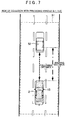
- the millimeter wave radar 15 is installed at a total of four locations, front, rear, right, and left surfaces, of the vehicle 2 as illustrated in FIG 7 , and the millimeter wave radar 15 is capable of detecting a position and relative speed of a target within a recognition range 51 around the host vehicle 2.
- FIG 7 for example, when there is a vehicle 52 traveling within the recognition range 51 of the millimeter wave radar 15 and in the same lane as the host vehicle 2, then the vehicle 52 is detected as a preceding vehicle at S1.
- the CPU 41 obtains the surrounding road conditions of the host vehicle.
- the surrounding road conditions obtained at S 13 include the condition of an adjacent lane that is next to the lane in which the host vehicle is currently traveling. Specifically, information (including the position and relative speed) pertaining to an object such as another vehicle traveling in the adjacent lane or a sign placed within the adjacent lane is obtained. Note that the detection of the surrounding road conditions is performed using the front camera 13, the rear camera 14, and the millimeter wave radar 15.
- the CPU 41 determines whether preceding vehicle information has been obtained in step S21. Thus, if it is determined that there is no preceding vehicle within the recognition range 51 of the millimeter radar 15, that is, if preceding vehicle information has not been obtained in step S21 (YES at S33), then the risk of a collision between the host vehicle and a preceding vehicle is considered eliminated as a result of performing the anti-collision control, and ending of the anti-collision control is determined (S32). The routine subsequently proceeds to S8.
Abstract
Description
- The present invention relates to a vehicle control device, a vehicle control method, and a computer program that perform an appropriate vehicle control when an object is detected ahead.
- Vehicle control devices have been proposed in the past for obtaining various information regarding vehicle travel such as a current position identified by GPS or the like and road information obtained from map data in a navigation device, as well as for providing driver notification and driving assistance, and for intervening with driving to prevent a vehicle accident. This type of vehicle control device performs a vehicle control at diverse timings and based on various conditions. In particular, when an object such as another vehicle ahead is detected during vehicle travel, in order to avoid contact with the object or mitigate damage upon contact, the vehicle control device performs braking to decelerate and turn the vehicle around.
- Japanese Patent Application Publication No.
JP-A-2007-145152 FIGS. 4 to 6 ), for example, describes art for performing a braking control, wherein based on a vehicle speed of a host vehicle, a speed of an object ahead of the host vehicle, and a positional relationship between the host vehicle and the object, it is determined whether contact with the object can be avoided by steering the host vehicle. If it is determined that contact with the object cannot be avoided by steering, then the braking control decelerates the vehicle. - In cases where the host vehicle is approaching an object ahead, the following two methods can be used in order to avoid contact with the object.
- (1) Maintain a distance from the object without contacting the object by performing host vehicle braking while keeping the current direction of vehicle travel.
- (2) Perform an avoidance maneuver by steering to change the travel direction of the host vehicle and moving the vehicle to the right or left of the object.
Comparing the above methods (1) and (2), in order to avoid contact with the object according to method (1), the driver must initiate a vehicle operation in order to avoid impact at a faster timing than that required to avoid contact with the object according to method (2). - According to the vehicle control device described in Japanese Patent Application Publication No.
JP-A-2007-145152 - However, the vehicle cannot avoid an object ahead by moving into the right or left adjacent lane if conditions do not allow such an avoidance maneuver, such as when there is no adjacent lane next to the lane in which the vehicle is traveling, or if there is an adjacent lane next to the lane in which the vehicle is traveling, but there is another object (e.g. a traveling vehicle) in the adjacent lane. If a determination is made based solely on a relative relationship between the host vehicle and the object as in the related art, then it is impossible to determine that the vehicle is in a situation where contact with the object cannot be avoided by steering as described above.
- The present invention was devised in order to resolve problems with the above related art, and it is an object of the present invention to provide a vehicle control device, a vehicle control method, and a computer program, which are capable of determining whether a vehicle is in a situation where contact with an object cannot be avoided through steering by using information pertaining to an adjacent lane and consequently reducing an impact upon contact with the object.
- According to a vehicle control device of a first aspect of the present invention, using information pertaining to adjacent lanes makes it possible to determine situations where contact with an object is unavoidable through steering, i.e., whether the vehicle is in a situation where contact with an object cannot be avoided regardless of any vehicle operation subsequently performed. As a consequence, the timing at which the braking control is initiated can be advanced, making it possible to reduce an impact upon contact with an object.
- According to the vehicle control device of a second aspect of the present invention, it is possible to determine whether contact with an object can be avoided through steering depending on whether there is an adjacent lane and whether there is another object positioned in the adjacent lane, and such a determination can be performed more accurately and faster than in the past.
- According to a vehicle control method of a third aspect of the present invention, using information pertaining to adjacent lanes makes it possible to determine situations where contact with an object is unavoidable through steering, i.e., whether the vehicle is in a situation where contact with an object cannot be avoided regardless of any vehicle operation subsequently performed. As a consequence, the timing at which the braking control is initiated can be advanced, making it possible to reduce an impact upon contact with an object.
- According to a computer program of a fourth aspect of the present invention, using information pertaining to adjacent lanes makes it possible for a computer to determine situations where contact with an object is unavoidable through steering, i.e., whether the vehicle is in a situation where contact with an object cannot be avoided regardless of any vehicle operation subsequently performed. As a consequence, the timing at which the braking control is initiated can be advanced, making it possible to reduce an impact upon contact with an object.
-
-
FIG 1 is a schematic configuration diagram of a vehicle control device according to an embodiment of the present invention; -
FIG 2 is a block diagram schematically showing a control system of a navigation device according to the present embodiment; -
FIG 3 is a flowchart of a vehicle control processing program executed by the vehicle control device according to the present embodiment; -
FIG 4 is a flowchart of a subroutine program in anti-collision control processing executed by the vehicle control device according to the present embodiment; -
FIG 5 is a flowchart of a subroutine program in control type determination processing executed by the vehicle control device according to the present embodiment; -
FIG 6 is a flowchart of a subroutine program in end determination processing executed by the vehicle control device according to the present embodiment; -
FIG 7 is a drawing showing an example where it is determined that a host vehicle may collide with a preceding vehicle; -
FIG 8 is a drawing showing an example where it is determined that a host vehicle will not collide with a preceding vehicle; -
FIG 9 is a drawing showing an example where it is determined that a collision with a preceding vehicle cannot be avoided through a steering operation; -
FIG 10 is a drawing showing an example where it is determined that a collision with a preceding vehicle cannot be avoided through a steering operation; and -
FIG 11 is a drawing showing an example where it is determined that a collision with a preceding vehicle can be avoided through a steering operation. - A vehicle control device according to the present invention will be described in detail below based on embodiments realizing the present invention and with reference to the drawings.
- A schematic configuration of a
vehicle control device 1 according to an embodiment will be explained first usingFIG 1. FIG 1 is a schematic configuration diagram of thevehicle control device 1 according to the present embodiment. - As illustrated in
FIG 1 , thevehicle control device 1 according to the present embodiment is structured from anavigation device 3, an engine 4, an automatic transmission (AT) 5,brakes 6A to 6D, an engine ECU 7, and an AT ECU 8, abrake ECU 9, a camera ECU 10, anaccelerator pedal 11, abrake pedal 12, afront camera 13, arear camera 14,millimeter wave radars vehicle 2. - Here, the
navigation device 3 is provided in a center console or panel screen in the interior of thevehicle 2. Thenavigation device 3 is equipped with a liquid crystal display that shows a map or a search route to a destination, and a speaker that outputs voice guidance related to route guidance. In addition to identifying a current position of thevehicle 2 using GPS or the like, if a destination is set, thenavigation device 3 also searches for a route to the destination and performs guidance in accordance with a set route using the liquid crystal display and the speaker. Furthermore, thenavigation device 3 according to the present embodiment performs a vehicle control (specifically, down-shifting the AT or not shifting the AT) that enables the most appropriate avoidance maneuver when an anti-collision control (described later) is performed. Thenavigation device 3 also performs a vehicle braking control for reducing an impact upon collision (specifically, shifting down the AT and increasing a brake pressure generated by thebrakes 6A to 6D). Thenavigation device 3 will be described in more detail later. - The engine 4 is an internal combustion engine or the like driven by a fuel such as gasoline, diesel, or ethanol, and is used as a drive source of the
vehicle 2. An engine torque that is the driving force of the engine 4 is transmitted to a vehicle wheel via the AT 5, a propeller shaft, and a drive shaft, thereby driving thevehicle 2. - The AT 5 is a transmission provided with a function for automatically changing a transmission gear ratio depending on a speed and an engine rpm. The AT 5 shifts the engine torque generated by the engine 4 and transmits the shifted torque to the propeller shaft. Note that in the present embodiment, either a shift-down control that increases a transmission gear ratio or a shift-hold control that fixes the transmission gear ratio are performed in the anti-collision control described later. Furthermore, the AT 5 may be a continuously variable transmission (CVT).
- The
brakes 6A to 6D are respectively provided corresponding to vehicle wheels disposed at the front and rear, and right and left sides of thevehicle 2, and are mechanisms that use friction to decrease a rotational speed of the vehicle wheels. Note that types of brakes include a drum brake and a disc brake. - The engine electronic control unit (ECU) 7 includes a CPU, a RAM, and a ROM (not shown), and is an electronic control unit that performs a control of the engine 4. The engine ECU 7 is connected with the
navigation device 3 and theaccelerator pedal 11. Based on operation of theaccelerator pedal 11, the engine ECU 7 controls an opening amount or the like of a throttle valve of the engine 4. - The AT ECU 8 includes a CPU, a RAM, and a ROM (not shown), and is an electronic control unit that performs a control of the
AT 5. The AT ECU 8 is connected with thenavigation device 3. Based on a command signal from thenavigation device 3, the AT ECU 8 controls a transmission gear ratio and the like of the AT. - The
brake ECU 9 includes a CPU, a RAM, and a ROM (not shown), and is an electronic control unit that performs a control of thebrakes 6A to 6D. Thebrake ECU 9 is connected with thenavigation device 3 and thebrake pedal 12. Based on a command signal from thenavigation device 3 or operation of thebrake pedal 12, thebrake ECU 9 controls a braking amount or the like generated by thebrakes 6A to 6D. - The
camera ECU 10 includes a CPU, a RAM, and a ROM (not shown), and is an electronic control unit that performs a control of thefront camera 13 and therear camera 14. - The
accelerator pedal 11 is provided on a driver seat side in the interior of thevehicle 2, and is operated by the driver. When the driver operates theaccelerator pedal 11, a depressed amount of theaccelerator pedal 11 is sent to theengine ECU 7, which adjusts an opening amount of the throttle valve. - The
brake pedal 12 is similarly provided on the driver seat side in the interior of thevehicle 2, and is operated by the driver. When the driver operates thebrake pedal 12, a depressed amount of thebrake pedal 12 is sent to thebrake ECU 9, which adjusts the braking amount. - The
front camera 13 and therear camera 14 use a solid-state image sensor such as a CCD, for example, and are attached near a central upper region of license plates mounted at the front and rear of thevehicle 2. Thefront camera 13 and therear camera 14 are installed such that a line of sight thereof faces a predetermined angle downward with respect to a horizontal level. During travel, an area ahead of the vehicle that is a travel direction of thevehicle 2 and an area behind the vehicle that is a reverse direction are respectively imaged. Thevehicle control device 1 detects surrounding road conditions of thevehicle 2, as well as center dividers and road markings such as lane markers that define lanes formed on the road surface around thevehicle 2, from images taken by thefront camera 13 and therear camera 14 as described later. Based on the detected lane marker and center divider, a lane in which thevehicle 2 is currently traveling (hereinafter referred to as a travel lane) is identified (e.g. thevehicle 2 traveling in the leftmost lane or thevehicle 2 traveling in the second lane from the right is identified). Note that the lane marker includes a road center line, a lane boundary line, a lane edge, a line indicating a pedestrian crosswalk, and the like. - The
millimeter wave radar 15 is an objection detection sensor whose recognition range encompasses a predetermined range around the vehicle (e.g. a range of 100 meters in front of and behind the vehicle 2), and is installed at a total of four locations: near the right and left door mirrors and near the central upper region of the license plates mounted at the front and back of thevehicle 2. Here, themillimeter wave radar 15 is formed from a radio wave sender and a radio wave receiver. Themillimeter wave radar 15 radiates a millimeter wave and receives a radio wave reflected from an object. Thevehicle control device 1 measures a position of an object and a speed of the object relative to the host vehicle based on a difference in frequency generated by a propagation time and the Doppler effect. Note that thevehicle control device 1 according to the present embodiment respectively detects the position and relative speed of another vehicle (object) traveling around the vehicle using themillimeter wave radar 15. - In the
vehicle control device 1 according to the present embodiment, an object such as another vehicle ahead of thevehicle 2 is detected and an anti-collision control is performed under conditions where there is a risk of thevehicle 2 crashing with the object. - The anti-collision control will be briefly explained here. In the anti-collision control, it is first determined from a running state of the vehicle and surrounding conditions whether a collision with an object can be avoided by a steering operation of the
vehicle 2. If it is determined that a collision with the object can be avoided by a steering operation, then theAT 5 is not shifted and a steering operation to avoid the object is recommended to the driver. Meanwhile, if it is determined that a collision with the object cannot be avoided by a steering operation, then a braking control of thevehicle 2 is performed wherein theAT 5 is shifted down and thebrakes 6A to 6D are operated. - Next, the
navigation device 3 structuring the abovevehicle control device 1 will be described in detail usingFIG 2. FIG 2 is a block diagram schematically showing a control system of anavigation device 3 according to the present embodiment. - As
FIG 2 illustrates, thenavigation device 3 according to the present embodiment is structured from the following: a currentposition detecting unit 21 that detects a current position of the host vehicle; adata recording unit 22 in which various data is recorded; a navigation ECU (a vehicle speed obtaining unit, an object distance obtaining unit, a collision judgment unit, an avoidance judgment unit, and a braking control unit) 23 that performs various computational processings based on input information; an operatingportion 24 that accepts an operation from a user; aliquid crystal display 25 that shows a map around the host vehicle for the user; aspeaker 26 that outputs voice guidance related to route guidance; aDVD drive 27 that reads out a DVD serving as a storage medium which stores a program; and acommunication module 28 that enables communication with an information center such as a traffic information center. Thenavigation ECU 23 is also connected with avehicle speed sensor 29 that detects a travel speed of the host vehicle and themillimeter wave radar 15 described earlier. - The structural components forming the
navigation device 3 will be explained in order below. - The current
position detecting unit 21 is formed from aGPS 31, ageomagnetic sensor 32, adistance sensor 33, asteering sensor 34, agyro sensor 35 serving as an orientation detecting unit, an altimeter (not shown), and the like, and is capable of detecting an orientation, current position, and so forth of the host vehicle. - The
data recording unit 22 is provided with a hard disk (not shown) that serves as an external storage device and a recording medium, as well as a recording head (not shown) that serves as a driver for reading amap information database 36 and a predetermined program or the like stored on the hard disk, and for writing predetermined data on the hard disk. - Here, the
map information database 36 stores various map data required for route guidance, traffic information guidance, and map display. Specifically, themap information database 36 is formed from link data pertaining to a road (link) configuration, node data pertaining to node points, road attribute data pertaining to road attributes, facility data pertaining to facilities such as restaurants and parking lots, intersection data pertaining to intersections, search data for searching a route, search data for searching a point, and image drawing data for drawing an image of a map, a road, traffic information, and so forth on theliquid crystal display 25. Note that the road attribute data includes information related to, for example, whether a road is one-way, the number of lanes on a road, a traffic lane width, a sidewalk width, and whether there is a center divider. - The navigation electronic control unit (ECU) 23 is an electronic control unit that performs overall controls of the
navigation device 3 such as guidance route setting processing that, when a destination is selected, sets a guidance route from the current position to the destination, in addition to the anti-collision control and the like. Furthermore, thenavigation ECU 23 is provided with aCPU 41 serving as a computing device and a control device, as well as internal memory devices such as the following: aRAM 42 that is used as a working memory when theCPU 41 performs various computational processing, and that also stores route data and the like when a route is searched; aROM 43 that stores a control program and a vehicle control processing program (seeFIGS. 3 to 6 ); and aflash memory 44 that records a program read out from theROM 43. - The operating
portion 24 is operated when inputting a place of departure that serves as a guidance start point and a destination that serves as a guidance end point, and is formed from a plurality of operation switches (not shown) that includes various keys and buttons. Based on switch signals output from the pressing of the switches or the like, thenavigation ECU 23 performs controls in order to execute various corresponding operations. Note that the operatingportion 24 can also be formed by a touch panel provided on a front screen of theliquid crystal display 25. - The
liquid crystal display 25 shows a road-including map image, traffic information, operation guidance, an operation menu, key guidance, a guidance route from the current position to the destination, guidance information along the guidance route, as well as news, a weather forecast, the time of day, mail, and television programs. In thenavigation device 3 according to the present embodiment in particular, during the anti-collision control, theliquid crystal display 25 shows a caution that recommends an avoidance operation and a caution that the braking control will be executed. - The
speaker 26 outputs traffic information guidance and voice guidance that guides travel along the guidance route based on a command from thenavigation ECU 23. In thenavigation device 3 according to the present embodiment in particular, during the anti-collision control, thespeaker 26 outputs voice guidance that recommends an avoidance operation and voice guidance that the braking control will be executed. - The
DVD drive 27 is a drive capable of reading data recorded on a recording medium such as a DVD or a CD. Based on the readout data, updating of themap information database 36 and the like is performed. - The
communication module 28 is a communication apparatus for receiving traffic information formed from information that includes congestion information, regulatory information, and traffic accident information sent from a VICS (registered trademark: Vehicle Information and Communication System) center, a probe center, or the like. Thecommunication module 28 corresponds to a mobile phone or a DCM, for example. - The
vehicle speed sensor 29 is a sensor for detecting a moving distance of the vehicle and a vehicle speed. Thevehicle speed sensor 29 generates a pulse in response to a rotation of the vehicle wheel, and outputs a pulse signal to thenavigation ECU 23. Thenavigation ECU 23 then calculates the moving distance based on the counted number of generated pulses. - Next, a vehicle control processing program executed by the
navigation ECU 23 in thevehicle control device 1 having the above configuration will be explained based onFIGS. 3 to 6 .FIG 3 is a flowchart of the vehicle control processing program according to the present embodiment. Here, the vehicle control processing program is repeatedly executed at a predetermined interval (e.g. 200 milliseconds) after an ignition of the vehicle is switched on, and is a program that performs an AT control based on whether avoidance of an object is possible after the object (e.g. another vehicle) is detected ahead in the travel direction of the vehicle. Note that the programs below shown in the flowcharts ofFIGS. 3 to 6 are stored in theRAM 42 and theROM 43 and executed by theCPU 41. The below embodiments describe examples in which a preceding vehicle in particular traveling ahead in the travel direction of the vehicle is detected as an object. - In the vehicle control processing program, first, the
CPU 41 at step (abbreviated to "S" below) 1 detects a preceding vehicle (object) at a position ahead in the travel direction of the host vehicle. Note that the detection of the preceding vehicle is performed using themillimeter wave radar 15. Here, themillimeter wave radar 15 is installed at a total of four locations, front, rear, right, and left surfaces, of thevehicle 2 as illustrated inFIG 7 , and themillimeter wave radar 15 is capable of detecting a position and relative speed of a target within arecognition range 51 around thehost vehicle 2. As shown inFIG 7 for example, when there is avehicle 52 traveling within therecognition range 51 of themillimeter wave radar 15 and in the same lane as thehost vehicle 2, then thevehicle 52 is detected as a preceding vehicle at S1. - Next at S2, the
CPU 41 detects a distance from the host vehicle to the preceding vehicle detected at S1 (namely, a following distance L1) using themillimeter wave radar 15. In the example shown inFIG 7 , a distance from thehost vehicle 2 to the precedingvehicle 52 is detected as the following distance L1. Note that S2 corresponds to the processing of the object distance obtaining unit. - At S3 the
CPU 41 detects the vehicle speed of the host vehicle using thevehicle speed sensor 29, and calculates a braking distance L2 of the host vehicle based on the detected vehicle speed. Here, the braking distance refers to a distance that the vehicle travels after the driver starts braking by pressing thebrake pedal 12 until the vehicle comes to a complete stop. Further note that the calculation method of the braking distance L2 is already known and therefore not explained here. Moreover, the braking distance L2 varies depending on the day's weather, a tire wear condition, a road inclination, and the like, and thenavigation device 3 is preferably structured so as to obtain such information in advance. Note that S3 corresponds to the processing of the vehicle speed obtaining unit. - Subsequently at S4 the
CPU 41 compares the following distance L1 to the preceding vehicle detected at S2 and the braking distance L2 of the host vehicle calculated at S3, and determines whether the following distance L1 is shorter than the braking distance L2. - Consequently, if it is determined that the following distance L1 is shorter than the braking distance L2 of the host vehicle as shown in
FIG 7 (YES at S4), then theCPU 41 determines that there is a risk of collision between the host vehicle and the preceding vehicle, and the routine proceeds to S5. At S5 theCPU 41 activates the anti-collision control. Note that the anti-collision control is a control that determines in advance a collision between the traveling vehicle and an object, and attempts to mitigate damage by operating safety equipment. In the present embodiment, the anti-collision control is a control of theAT 5 that especially considers the possibility of a collision with an object. - Meanwhile, if it is determined that the following distance L1 is longer than the braking distance L2 of the host vehicle as shown in
FIG 8 (NO at S4), then theCPU 41 determines that there is no risk of collision between the host vehicle and the preceding vehicle. The anti-collision control is not activated and the vehicle control processing is ended. Note that S4 corresponds to the processing of the collision judgment unit. - Next at S6, the
CPU 41 executes anti-collision control processing described later (FIG. 4 ). Note that the anti-collision control processing is processing that determines whether a collision between the host vehicle and the preceding vehicle can be avoided by a steering operation and performs a control of theAT 5 based on the determination result. - Next at S7, the
CPU 41 executes end determination processing described later (FIG 6 ). Note that the end determination processing is processing that determines whether the risk of a collision between the host vehicle and the preceding vehicle has been eliminated as a result of performing the anti-collision control. - At S8 it is determined whether to end the anti-collision control based on the result of the end determination processing at S7. Specifically, if it is determined at S7 that the risk of a collision between the host vehicle and the preceding vehicle is eliminated, then the anti-collision control is ended; if it is determined that the risk of a collision between the host vehicle and the preceding vehicle is not eliminated, then it is judged that the anti-collision control should be continued.
- If it is judged that the anti-collision control should be continued as a result of the determination at S8 (NO at S8), then the routine returns to S6 and the anti-collision control is continued. On the other hand, if it is determined that the anti-collision control should be ended (YES at S8), then the vehicle control processing is ended.
- A subroutine of the anti-collision control processing at S6 will be explained next based on
FIG 4. FIG 4 is a flowchart of a subroutine program in the anti-collision control processing. - At S11 the
CPU 41 first obtains host vehicle information pertaining to the host vehicle. Here, the host vehicle information obtained atS 11 includes the current position, travel direction, vehicle speed, and lane position of the host vehicle. Note that regarding the current position of the host vehicle, a detection result of theGPS 31 and map-matching processing employing the map data stored in themap information database 36 are used to identify the current position of the host vehicle on a map. The travel direction and the vehicle speed of the host vehicle are detected using thegyro sensor 35 and thevehicle speed sensor 29. In addition, the lane position in which the host vehicle is traveling is identified based on an image taken by therear camera 14. - The processing for identifying the lane position in which the host vehicle is traveling will be briefly described below. First the
CPU 41 performs image recognition processing of a lane marker and a center divider from an image taken by therear camera 14. Based on the result of the image recognition processing, the existence of a lane marker and a center divider, as well as the type of lane marker are detected. Next the traffic lane in which the host vehicle is traveling is identified based on the detected lane marker and center divider, and the configuration of the road in which the host vehicle is currently traveling as obtained from themap information database 36. Note that if the road in which the host vehicle is traveling has only one lane, then there is no need to performing the processing pertaining to identification of the lane position. - At S12 the
CPU 41 next obtains preceding vehicle information pertaining to the preceding vehicle. Here, the preceding vehicle information obtained at S12 includes the following distance L1 detected at S2 from the host vehicle to the preceding vehicle and the relative speed of the preceding vehicle with respect to the host vehicle. Note that the detection of the relative speed of the preceding vehicle is performed using themillimeter wave radar 15. - At
S 13 theCPU 41 obtains the surrounding road conditions of the host vehicle. Here, the surrounding road conditions obtained atS 13 include the condition of an adjacent lane that is next to the lane in which the host vehicle is currently traveling. Specifically, information (including the position and relative speed) pertaining to an object such as another vehicle traveling in the adjacent lane or a sign placed within the adjacent lane is obtained. Note that the detection of the surrounding road conditions is performed using thefront camera 13, therear camera 14, and themillimeter wave radar 15. - Next at
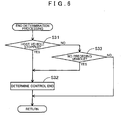
S 14, theCPU 41 performs control type determination processing described later (FIG. 5 ). Note that the control type determination processing is processing that determines the appropriate type of control to be performed by the anti-collision control: (a) an avoidance control that recommends an avoidance maneuver to the driver in order to prevent a collision with an object, and (b) a braking control for deceleration in order to mitigate an impact upon collision with an object. - At S15 the
CPU 41 determines whether either (a) the avoidance control or (b) the braking control has been selected as a result of the control type determination processing atS 14. - If (a) the avoidance control has consequently been selected, then the
CPU 41 performs a shift-hold control that fixes a transmission gear ratio of theAT 5 via the AT ECU 8 (S16). Thus, even when the vehicle performs an avoidance maneuver as a result of steering by the driver, there is no down-shifting during the avoidance maneuver, thereby suppressing skidding or the like of the vehicle. It is also preferable that at S 16 a caution regarding the execution of an avoidance maneuver is simultaneously conveyed using theliquid crystal display 25 and thespeaker 26. Note that in addition to the caution regarding the execution of an avoidance maneuver, guidance regarding a steering direction may also be provided. Furthermore, an automatic control for steering assistance may also be performed. - Meanwhile, if (b) the braking control has consequently been selected, then the
CPU 41 performs a shift-down control that increases the transmission gear ratio of theAT 5 via the AT ECU 8 (S17). Thus, even if a collision with the object cannot be avoided, it is possible to mitigate an impact upon collision due to braking of the vehicle generated by an engine brake. At S 17 the braking control is preferably performed simultaneously by thebrakes 6A to 6D. It is also preferable that a caution regarding the execution of the braking control is conveyed using theliquid crystal display 25 and thespeaker 26. Note that S17 corresponds to the processing of the braking control unit. - A subroutine of the control type determination processing at
S 14 will be explained next based onFIG 5. FIG 5 is a flowchart of a subroutine program in the control type determination processing. - At S21 the
CPU 41 first determines whether the vehicle speed of the host vehicle obtained atS 11 is less than a turnable speed. Note that the turnable speed is a speed at which the vehicle can safely turn, and is set as a parameter per vehicle. - If it is determined that the vehicle speed of the host vehicle is less than the turnable speed (YES at S21), then the routine proceeds to S22. Meanwhile, if it is determined that the vehicle speed of the host vehicle is equal to or greater than the turnable speed (NO at S21), then it is dangerous for the vehicle to perform an avoidance maneuver. Therefore, it is determined that the braking control for deceleration in order to mitigate an impact upon collision with the object is appropriate as the type of control performed by the anti-collision control (S27).
- At S22 the
CPU 41 calculates a distance required to avoid the preceding vehicle (hereinafter referred to as a required avoidance distance L3) based on the host vehicle information obtained at S11 and the preceding vehicle information obtained at S12. - Subsequently at S23 the
CPU 41 compares the required avoidance distance L3 obtained at S22 and the following distance L1 to the preceding vehicle, and determines whether the required avoidance distance L3 is shorter than the following distance L1. - If it is determined that the required avoidance distance L3 is shorter than the following distance L1 (YES at S23), then the routine proceeds to S24. Meanwhile, if it is determined that the required avoidance distance L3 is longer than the following distance L1 at illustrated in
FIG 9 (NO at S23), then contact with the preceding vehicle cannot be avoided. Therefore, it is determined that the braking control for deceleration in order to mitigate an impact upon collision with the object is appropriate as the type of control performed by the anti-collision control (S27). Note that, when the preceding vehicle information has not been obtained in step S12, theCPU 41 determines in step S23 that the required avoidance distance L3 is longer than the following distance L1 as illustrated inFig. 9 (NO in S23). - At S24 the
CPU 41 determines whether there is a lane adjacent to the lane in which the host vehicle is currently traveling based on road information pertaining to the road on which the host vehicle is currently traveling. If it is determined that there is an adjacent lane (YES at S24), then the routine proceeds to S25. Meanwhile, if it is determined that no adjacent lane exists (NO at S24), then the preceding vehicle cannot be avoided. Therefore, it is determined that the braking control for deceleration in order to mitigate an impact upon collision with the object is appropriate as the type of control performed by the anti-collision control (S27). - At S25 the
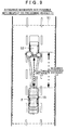
CPU 41 determines whether there is an object (e.g. a vehicle, sign, or the like) at a distance closer than the preceding vehicle in an adjacent lane next to the lane in which the host vehicle is currently traveling based on the surrounding road conditions obtained atS 13. - Thus, if it is determined that there is an object at a distance closer than the preceding vehicle in all adjacent lanes (NO at S25), then routes for avoiding the preceding vehicle are blocked by the objects, making contact with the preceding vehicle unavoidable. Therefore, it is determined that the braking control for deceleration in order to mitigate an impact upon collision with the object is appropriate as the type of control performed by the anti-collision control (S27). In the example illustrated in
FIG. 10 for example, there is avehicle 53 in a left adjacent lane between thehost vehicle 2 and the precedingvehicle 52, and there is avehicle 54 in a right adjacent lane between thehost vehicle 2 and the precedingvehicle 52. Thus, thevehicle 53 blocks a route in which thehost vehicle 2 moves to the left in order to avoid the precedingvehicle 52, and thevehicle 54 blocks a route in which thehost vehicle 2 moves to the right in order to avoid the precedingvehicle 52. In such cases, the braking control is selected as the type of control performed by the anti-collision control. - On the other hand, if it is determined that no object exists at a distance closer than the preceding vehicle in at least one adjacent lane (YES at S25), then in the adjacent lane without an object a route for avoiding the preceding vehicle is not blocked by an object, and contact with the preceding vehicle is avoidable through a steering operation. Therefore, it is determined that the avoidance control that recommends an avoidance maneuver to the driver is appropriate as the type of control performed by the anti-collision control (S26). For example, in
FIG. 11 there is no object between thehost vehicle 2 and the precedingvehicle 52 in the right and left adjacent lanes, and the required avoidance distance L3 is shorter than the following distance L1. It is thus possible to avoid the precedingvehicle 52 through a steering operation. Note that S21 to S25 correspond to the processing of the avoidance judgment unit. - In cases where the host vehicle is approaching an object ahead, the following two methods here can be used in order to avoid contact with the object.
- (1) Maintain a distance from the object without contacting the object by performing vehicle braking while keeping to the current direction of vehicle travel.
- (2) Perform an avoidance maneuver by steering to change the travel direction of the host vehicle and moving the vehicle to the right or left of the object.
Comparing the above methods (1) and (2), in order to avoid contact with the object according to method (1), the driver must initiate a vehicle operation in order to avoid impact at a faster timing than that required to avoid contact with the object according to method (2). - According to related art (see Japanese Patent Application Publication No.
JP-A-2007145152 - However, the vehicle cannot avoid an object ahead by moving into the right or left adjacent lane if conditions do not allow such an avoidance maneuver, such as when there is no adjacent lane next to the lane in which the vehicle is traveling, or if there is an adjacent lane next to the lane in which the vehicle is traveling, there is another object (e.g. a traveling vehicle) in the adjacent lane. If a determination is made based solely on a relative relationship between the host vehicle and the object as in the related art, then it is impossible to determine that the vehicle is in a situation where contact with the object cannot be avoided by steering as described above.
- Hence, in the present embodiment, by using information regarding whether there is an adjacent lane next to the lane in which the vehicle is traveling and whether there is an object in the adjacent lane, the determination processing at S24 and S25 is added so that it can be determined whether the vehicle is in a situation where contact with the object cannot be avoided by steering. As a consequence, the timing at which the braking control (S 17) is initiated can be advanced, making it possible to reduce an impact upon contact with an object.
- A sub-routine of the end determination processing at S7 will be explained next based on
FIG. 6. FIG. 6 is a flowchart of a sub-routine program in the end termination processing. - At S31 the
CPU 41 first determines whether the host vehicle is stopped using thevehicle speed sensor 29. If it is determined that the host vehicle is stopped (YES at S31), then there is no risk of the host vehicle subsequently contacting an object. Therefore, ending of the anti-collision control is determined (S32). - Meanwhile, if it is determined that the host vehicle is traveling (NO at S31), then it is further determined at S33 whether there is a preceding vehicle within the
recognition range 51 of themillimeter wave radar 15. In particular, theCPU 41 determines whether preceding vehicle information has been obtained in step S21. Thus, if it is determined that there is no preceding vehicle within therecognition range 51 of themillimeter radar 15, that is, if preceding vehicle information has not been obtained in step S21 (YES at S33), then the risk of a collision between the host vehicle and a preceding vehicle is considered eliminated as a result of performing the anti-collision control, and ending of the anti-collision control is determined (S32). The routine subsequently proceeds to S8. - On the other hand, if it is determined that there is a preceding vehicle within the
recognition range 51 of themillimeter radar 15, that is, if preceding vehicle information has been obtained in step S21 (NO at S33), then the risk of a collision between the host vehicle and a preceding vehicle is not eliminated. Continuation of the anti-collision control is determined, and the routine proceeds to S8. - As described in detail above, according to the
vehicle control device 1, the vehicle control method used by thevehicle control device 1, and the computer program executed by thevehicle control device 1 of the present embodiment, if a preceding vehicle is detected ahead traveling in the travel direction of the vehicle (S1), then the following distance to the preceding vehicle is detected (S2), and the braking distance of the host vehicle is calculated (S3). If a risk of collision between the host vehicle and the preceding vehicle is determined, then the anti-collision control is performed (S6). In the anti-collision control, it is determined whether a collision with the preceding vehicle can be avoided through a steering operation by taking into consideration the host vehicle information, the preceding vehicle information, and the surrounding road conditions (S21 to S27). If avoidance is determined as possible, then the shift-hold control is applied to the AT 5 (S 16), whereas if avoidance is determined as impossible, then the shift-down control is applied to the AT 5 (S 17). Therefore, skidding or the like can be suppressed during an avoidance maneuver performed by thehost vehicle 2. Accordingly, the preceding vehicle can be surely avoided with the behavior of thehost vehicle 2 stabilized, thereby enabling safe driving. - Moreover, by comparing the braking distance calculated based on the vehicle speed of the
host vehicle 2 and the distance to the preceding vehicle (S4), it is possible to accurately determine whether there is a risk of collision between the vehicle and the object. - Taking into consideration the vehicle traveling in an adjacent lane also makes it possible to know whether an avoidance route to an adjacent lane can be secured for the
host vehicle 2 to avoid the object (S25). Using the result found regarding whether an avoidance route can be secured enables a more accurate determination as to whether a collision between thehost vehicle 2 and the preceding vehicle can be avoided through a steering operation. - Also, using information pertaining to adjacent lanes makes it possible to determine situations where contact with an object is unavoidable through steering, i.e., whether the vehicle is in a situation where contact with an object cannot be avoided regardless of any vehicle operation subsequently performed (S24, S25). As a consequence, the timing at which the braking control (S 17) is initiated can be advanced, making it possible to reduce an impact upon contact with an object.
- If no adjacent lane exists next to the lane in which the vehicle is traveling, then it is determined that a collision between an object and the vehicle is unavoidable, and if there is an adjacent lane next to the lane in which the vehicle is traveling but there is another object in the adjacent lane, then it is also determined that a collision between the object and the vehicle is unavoidable. Therefore, a more accurate and prompt determination regarding whether contact with an object is avoidable through steering can be performed than in the past.
- Note that the present invention is not limited to the above embodiment, and various improvements and modifications are naturally possible within the scope of the present invention.
- The present embodiment describes an example in which a preceding vehicle in particular traveling ahead in the travel direction of the vehicle is detected as an object. However, the object may be something other than a preceding vehicle. The object may instead correspond to a person, a bicycle, a guardrail, or the like.
- Furthermore, in the present embodiment, the
navigation ECU 23 provided in thenavigation device 3 executes the vehicle control processing program shown inFIGS. 3 to 6 . However, the vehicle control processing program may be executed instead by theengine ECU 7, theAT ECU 8, thebrake ECU 9, or the like. Processing may also be divided and performed by a plurality of ECUs. - It is explicitly stated that all features disclosed in the description and/or the claims are intended to be disclosed separately and independently from each other for the purpose of original disclosure as well as for the purpose of restricting the claimed invention independent of the composition of the features in the embodiments and/or the claims. It is explicitly stated that all value ranges or indications of groups of entities disclose every possible intermediate value or intermediate entity for the purpose of original disclosure as well as for the purpose of restricting the claimed invention, in particular as limits of value ranges.
Claims (4)
- A vehicle control device (1), comprisinga vehicle speed obtaining unit (29) that is adapted to obtain a vehicle speed of a vehicle (2),an object distance obtaining unit (15) that is adapted to obtain a distance (L1) to an object (52) ahead of the vehicle (2),a collision judgment unit (23) that is adapted to determine whether there is a risk of a collision between the object (52) and the vehicle (2) based on the vehicle speed and the distance to the object,an avoidance judgment unit (23) that, following a determination by the collision judgment unit that there is a risk of a collision between the object (52) and the vehicle (2), adapted to determine whether the collision between the object and the vehicle can be avoided through a steering operation based on whether there is an adjacent lane next to a lane in which the vehicle (2) is traveling, anda braking control unit (23) that is adapted to perform a braking control for decelerating the vehicle following a determination by the avoidance judgment unit that a collision between the object and the vehicle cannot be avoided by a steering operation.
- The vehicle control device according to claim 1, whereinthe avoidance judgment unit (23) is adapted todetermine that a collision between the object (52) and the vehicle (2) is unavoidable if there is no adjacent lane next to the lane in which the vehicle is traveling, anddetermine that a collision between the object and the vehicle is unavoidable if there is an adjacent lane next to the lane in which the vehicle is traveling but there is another object in the adjacent lane.
- A vehicle control method comprising the steps of:obtaining a vehicle speed of a vehicle (2);obtaining a distance (L1) to an object (52) ahead of the vehicle (2);performing a collision judgement by determining whether there is a risk of a collision between the object (52) and the vehicle (2) based on the vehicle speed and the distance (L1) to the object;following a determination at the collision judgement step that there is a risk of a collision between the object and the vehicle, performing an avoidance judgement by determining whether the collision between the object and the vehicle can be avoided through a steering operation based on whether there is an adjacent lane next to a lane in which the vehicle is traveling; andperforming a braking control for decelerating the vehicle following a determination at the avoidance judgment step that a collision between the object and the vehicle cannot be avoided by a steering operation.
- A computer program including program code which, when run in a computer, performs the steps of the method of claim 3.
Applications Claiming Priority (3)
| Application Number | Priority Date | Filing Date | Title |
|---|---|---|---|
| JP2007298079 | 2007-11-16 | ||
| JP2008068946A JP5309633B2 (en) | 2007-11-16 | 2008-03-18 | Vehicle control apparatus, vehicle control method, and computer program |
| JP2008086132A JP2009137562A (en) | 2007-11-16 | 2008-03-28 | Vehicle control device, vehicle control method, and computer program |
Publications (2)
| Publication Number | Publication Date |
|---|---|
| EP2060455A1 true EP2060455A1 (en) | 2009-05-20 |
| EP2060455B1 EP2060455B1 (en) | 2012-08-08 |
Family
ID=40227639
Family Applications (1)
| Application Number | Title | Priority Date | Filing Date |
|---|---|---|---|
| EP20080019108 Expired - Fee Related EP2060455B1 (en) | 2007-11-16 | 2008-10-31 | Vehicle control device, vehicle control method, and computer program |
Country Status (1)
| Country | Link |
|---|---|
| EP (1) | EP2060455B1 (en) |
Cited By (8)
| Publication number | Priority date | Publication date | Assignee | Title |
|---|---|---|---|---|
| GB2485873A (en) * | 2010-11-22 | 2012-05-30 | Gm Global Tech Operations Inc | A method of evading an approaching motor vehicle in same lane |
| US20150345964A1 (en) * | 2014-05-30 | 2015-12-03 | Denso Corporation | Evacuation travelling assistance apparatus |
| EP2763120A4 (en) * | 2011-09-26 | 2016-08-17 | Toyota Motor Co Ltd | Vehicle driving assistance system |
| CN106846902A (en) * | 2015-12-03 | 2017-06-13 | 财团法人资讯工业策进会 | Vehicle collision avoidance system and method |
| CN106846901A (en) * | 2015-12-03 | 2017-06-13 | 财团法人资讯工业策进会 | Avoid the System and method for of abnormal vehicle |
| EP3473510A3 (en) * | 2010-10-05 | 2019-07-24 | Waymo LLC | Maneuevering autonomous vehicles |
| CN110239531A (en) * | 2018-03-08 | 2019-09-17 | 株式会社万都 | Device and method for controlling collision prevention of vehicle |
| US10759420B2 (en) | 2013-01-25 | 2020-09-01 | Wabco Gmbh | Method for determining an activation criterion for a brake application and emergency brake system for performing the method |
Citations (7)
| Publication number | Priority date | Publication date | Assignee | Title |
|---|---|---|---|---|
| US6353788B1 (en) | 1997-12-15 | 2002-03-05 | Robert Bosch Gmbh | Method for regulating speed and distance during passing maneuvers |
| US20040145238A1 (en) | 2003-01-24 | 2004-07-29 | Nissan Motor Co., Ltd. | Braking control device |
| US20040155811A1 (en) | 2001-03-26 | 2004-08-12 | Domenico Albero | Motor vehicle driving aid system |
| JP2004237813A (en) | 2003-02-04 | 2004-08-26 | Nissan Motor Co Ltd | Brake controlling system for vehicle |
| US20040193374A1 (en) | 2003-03-28 | 2004-09-30 | Hac Aleksander B. | Collision avoidance with active steering and braking |
| JP2005138623A (en) | 2003-11-04 | 2005-06-02 | Toyota Motor Corp | Vehicle travel supporting device |
| JP2007034988A (en) | 2005-07-29 | 2007-02-08 | Nissan Motor Co Ltd | Obstacle avoidance warning device for vehicle |
-
2008
- 2008-10-31 EP EP20080019108 patent/EP2060455B1/en not_active Expired - Fee Related
Patent Citations (7)
| Publication number | Priority date | Publication date | Assignee | Title |
|---|---|---|---|---|
| US6353788B1 (en) | 1997-12-15 | 2002-03-05 | Robert Bosch Gmbh | Method for regulating speed and distance during passing maneuvers |
| US20040155811A1 (en) | 2001-03-26 | 2004-08-12 | Domenico Albero | Motor vehicle driving aid system |
| US20040145238A1 (en) | 2003-01-24 | 2004-07-29 | Nissan Motor Co., Ltd. | Braking control device |
| JP2004237813A (en) | 2003-02-04 | 2004-08-26 | Nissan Motor Co Ltd | Brake controlling system for vehicle |
| US20040193374A1 (en) | 2003-03-28 | 2004-09-30 | Hac Aleksander B. | Collision avoidance with active steering and braking |
| JP2005138623A (en) | 2003-11-04 | 2005-06-02 | Toyota Motor Corp | Vehicle travel supporting device |
| JP2007034988A (en) | 2005-07-29 | 2007-02-08 | Nissan Motor Co Ltd | Obstacle avoidance warning device for vehicle |
Cited By (14)
| Publication number | Priority date | Publication date | Assignee | Title |
|---|---|---|---|---|
| EP3473510A3 (en) * | 2010-10-05 | 2019-07-24 | Waymo LLC | Maneuevering autonomous vehicles |
| US11287817B1 (en) | 2010-10-05 | 2022-03-29 | Waymo Llc | System and method of providing recommendations to users of vehicles |
| US11010998B1 (en) | 2010-10-05 | 2021-05-18 | Waymo Llc | Systems and methods for vehicles with limited destination ability |
| US8620526B2 (en) | 2010-11-22 | 2013-12-31 | GM Global Technology Operations LLC | Method for operating a motor vehicle and motor vehicle |
| GB2485873A (en) * | 2010-11-22 | 2012-05-30 | Gm Global Tech Operations Inc | A method of evading an approaching motor vehicle in same lane |
| EP2763120A4 (en) * | 2011-09-26 | 2016-08-17 | Toyota Motor Co Ltd | Vehicle driving assistance system |
| US10759420B2 (en) | 2013-01-25 | 2020-09-01 | Wabco Gmbh | Method for determining an activation criterion for a brake application and emergency brake system for performing the method |
| US9766085B2 (en) * | 2014-05-30 | 2017-09-19 | Denso Corporation | Evacuation travelling assistance apparatus |
| US20150345964A1 (en) * | 2014-05-30 | 2015-12-03 | Denso Corporation | Evacuation travelling assistance apparatus |
| CN106846901B (en) * | 2015-12-03 | 2019-07-05 | 财团法人资讯工业策进会 | Avoid the System and method for of abnormal vehicle |
| CN106846901A (en) * | 2015-12-03 | 2017-06-13 | 财团法人资讯工业策进会 | Avoid the System and method for of abnormal vehicle |
| CN106846902A (en) * | 2015-12-03 | 2017-06-13 | 财团法人资讯工业策进会 | Vehicle collision avoidance system and method |
| CN110239531A (en) * | 2018-03-08 | 2019-09-17 | 株式会社万都 | Device and method for controlling collision prevention of vehicle |
| CN110239531B (en) * | 2018-03-08 | 2022-06-10 | 万都移动系统股份公司 | Apparatus and method for controlling vehicle collision avoidance |
Also Published As
| Publication number | Publication date |
|---|---|
| EP2060455B1 (en) | 2012-08-08 |
Similar Documents
| Publication | Publication Date | Title |
|---|---|---|
| US8423250B2 (en) | Vehicle control device, vehicle control method and computer program | |
| EP2060455B1 (en) | Vehicle control device, vehicle control method, and computer program | |
| US10643474B2 (en) | Vehicle control device, vehicle control method, and recording medium | |
| US8040253B2 (en) | Lane-change assistant for motor vehicles | |
| EP2019382B1 (en) | Support control device | |
| EP1919752B1 (en) | Vehicle equipped with a control apparatus and vehicle control method | |
| JP4134894B2 (en) | Vehicle driving support device | |
| CN102132335B (en) | Traveling environment recognition device | |
| EP2264683A1 (en) | Driving support device and program | |
| US20050015203A1 (en) | Lane-changing support system | |
| EP1787849A1 (en) | Driving assist method and driving assist apparatus for vehicle | |
| US10754335B2 (en) | Automated driving system | |
| JP2005107693A (en) | Device and program for detecting travel position of one's own vehicle | |
| JP6573594B2 (en) | Automatic operation control device | |
| JP4899429B2 (en) | Driving support device | |
| JP2005165423A (en) | Vehicle-driving support device | |
| CN113386752A (en) | Method and device for determining an optimal cruising lane in a driver assistance system | |
| JP3575352B2 (en) | Vehicle position locating device and recording medium | |
| EP3730368A1 (en) | Vehicle control device, method and computer program product | |
| JP3672914B2 (en) | Vehicle alarm device | |
| JP2003072415A (en) | Vehicular travel control device | |
| EP4212400A1 (en) | Driving assistance method and driving assistance device | |
| JP2020199810A (en) | Vehicle control apparatus, vehicle, method for operating vehicle control apparatus, and program | |
| JP7304334B2 (en) | VEHICLE CONTROL DEVICE, VEHICLE CONTROL METHOD, AND PROGRAM | |
| WO2023152960A1 (en) | Construction zone determining method and construction zone determining device |
Legal Events
| Date | Code | Title | Description |
|---|---|---|---|
| PUAI | Public reference made under article 153(3) epc to a published international application that has entered the european phase |
Free format text: ORIGINAL CODE: 0009012 |
|
| AK | Designated contracting states |
Kind code of ref document: A1 Designated state(s): AT BE BG CH CY CZ DE DK EE ES FI FR GB GR HR HU IE IS IT LI LT LU LV MC MT NL NO PL PT RO SE SI SK TR |
|
| AX | Request for extension of the european patent |
Extension state: AL BA MK RS |
|
| RIN1 | Information on inventor provided before grant (corrected) |
Inventor name: MIYAHIMA, TAKAYUKI Inventor name: KONDOU, YOSHITO Inventor name: YASUI, YOSHIYUKI Inventor name: KODAMA, HIROYUKI Inventor name: TAKEUCHI, ATSUSHI |
|
| RIN1 | Information on inventor provided before grant (corrected) |
Inventor name: MIYAJIMA, TAKAYUKI Inventor name: KONDOU, YOSHITO Inventor name: KODAMA, HIROYUKI Inventor name: YASUI, YOSHIYUKI Inventor name: TAKEUCHI, ATSUSHI |
|
| 17P | Request for examination filed |
Effective date: 20091120 |
|
| AKX | Designation fees paid |
Designated state(s): DE |
|
| 17Q | First examination report despatched |
Effective date: 20100706 |
|
| GRAP | Despatch of communication of intention to grant a patent |
Free format text: ORIGINAL CODE: EPIDOSNIGR1 |
|
| GRAS | Grant fee paid |
Free format text: ORIGINAL CODE: EPIDOSNIGR3 |
|
| GRAA | (expected) grant |
Free format text: ORIGINAL CODE: 0009210 |
|
| RIN1 | Information on inventor provided before grant (corrected) |
Inventor name: KODAMA, HIROYUKI Inventor name: MIYAJIMA, TAKAYUKI Inventor name: KONDOU, YOSHITO Inventor name: TAKEUCHI, ATSUSHI Inventor name: YASUI, YOSHIYUKI |
|
| AK | Designated contracting states |
Kind code of ref document: B1 Designated state(s): DE |
|
| REG | Reference to a national code |
Ref country code: DE Ref legal event code: R096 Ref document number: 602008017741 Country of ref document: DE Effective date: 20121004 |
|
| PLBE | No opposition filed within time limit |
Free format text: ORIGINAL CODE: 0009261 |
|
| STAA | Information on the status of an ep patent application or granted ep patent |
Free format text: STATUS: NO OPPOSITION FILED WITHIN TIME LIMIT |
|
| 26N | No opposition filed |
Effective date: 20130510 |
|
| REG | Reference to a national code |
Ref country code: DE Ref legal event code: R097 Ref document number: 602008017741 Country of ref document: DE Effective date: 20130510 |
|
| PGFP | Annual fee paid to national office [announced via postgrant information from national office to epo] |
Ref country code: DE Payment date: 20191015 Year of fee payment: 12 |
|
| REG | Reference to a national code |
Ref country code: DE Ref legal event code: R119 Ref document number: 602008017741 Country of ref document: DE |
|
| PG25 | Lapsed in a contracting state [announced via postgrant information from national office to epo] |
Ref country code: DE Free format text: LAPSE BECAUSE OF NON-PAYMENT OF DUE FEES Effective date: 20210501 |