EP2065117A1 - Method and machine tool for process visualisation of machining process of a workpiece - Google Patents
Method and machine tool for process visualisation of machining process of a workpiece Download PDFInfo
- Publication number
- EP2065117A1 EP2065117A1 EP07023148A EP07023148A EP2065117A1 EP 2065117 A1 EP2065117 A1 EP 2065117A1 EP 07023148 A EP07023148 A EP 07023148A EP 07023148 A EP07023148 A EP 07023148A EP 2065117 A1 EP2065117 A1 EP 2065117A1
- Authority
- EP
- European Patent Office
- Prior art keywords
- processing
- material processing
- workpiece
- process image
- image
- Prior art date
- Legal status (The legal status is an assumption and is not a legal conclusion. Google has not performed a legal analysis and makes no representation as to the accuracy of the status listed.)
- Withdrawn
Links
Images
Classifications
-
- B—PERFORMING OPERATIONS; TRANSPORTING
- B23—MACHINE TOOLS; METAL-WORKING NOT OTHERWISE PROVIDED FOR
- B23K—SOLDERING OR UNSOLDERING; WELDING; CLADDING OR PLATING BY SOLDERING OR WELDING; CUTTING BY APPLYING HEAT LOCALLY, e.g. FLAME CUTTING; WORKING BY LASER BEAM
- B23K26/00—Working by laser beam, e.g. welding, cutting or boring
- B23K26/36—Removing material
- B23K26/38—Removing material by boring or cutting
-
- B—PERFORMING OPERATIONS; TRANSPORTING
- B23—MACHINE TOOLS; METAL-WORKING NOT OTHERWISE PROVIDED FOR
- B23K—SOLDERING OR UNSOLDERING; WELDING; CLADDING OR PLATING BY SOLDERING OR WELDING; CUTTING BY APPLYING HEAT LOCALLY, e.g. FLAME CUTTING; WORKING BY LASER BEAM
- B23K26/00—Working by laser beam, e.g. welding, cutting or boring
- B23K26/02—Positioning or observing the workpiece, e.g. with respect to the point of impact; Aligning, aiming or focusing the laser beam
- B23K26/03—Observing, e.g. monitoring, the workpiece
- B23K26/032—Observing, e.g. monitoring, the workpiece using optical means
-
- B—PERFORMING OPERATIONS; TRANSPORTING
- B23—MACHINE TOOLS; METAL-WORKING NOT OTHERWISE PROVIDED FOR
- B23K—SOLDERING OR UNSOLDERING; WELDING; CLADDING OR PLATING BY SOLDERING OR WELDING; CUTTING BY APPLYING HEAT LOCALLY, e.g. FLAME CUTTING; WORKING BY LASER BEAM
- B23K26/00—Working by laser beam, e.g. welding, cutting or boring
- B23K26/08—Devices involving relative movement between laser beam and workpiece
- B23K26/0869—Devices involving movement of the laser head in at least one axial direction
- B23K26/0876—Devices involving movement of the laser head in at least one axial direction in at least two axial directions
-
- B—PERFORMING OPERATIONS; TRANSPORTING
- B23—MACHINE TOOLS; METAL-WORKING NOT OTHERWISE PROVIDED FOR
- B23K—SOLDERING OR UNSOLDERING; WELDING; CLADDING OR PLATING BY SOLDERING OR WELDING; CUTTING BY APPLYING HEAT LOCALLY, e.g. FLAME CUTTING; WORKING BY LASER BEAM
- B23K26/00—Working by laser beam, e.g. welding, cutting or boring
- B23K26/20—Bonding
- B23K26/21—Bonding by welding
-
- G—PHYSICS
- G02—OPTICS
- G02B—OPTICAL ELEMENTS, SYSTEMS OR APPARATUS
- G02B21/00—Microscopes
- G02B21/0004—Microscopes specially adapted for specific applications
- G02B21/0016—Technical microscopes, e.g. for inspection or measuring in industrial production processes
Definitions
- the invention relates to a method for process visualization of a machining of a workpiece and to a machine tool with a process visualization for machining a workpiece.
- a processing machine with the name PowerWeld of Trumpf Laser GmbH + Co. KG is already known, in which a closed working space is provided.
- a closed working space is provided.
- an air bearing worktop for receiving a workpiece is provided, said air bearing worktop allows easy positioning of the workpiece to the workpiece relative to a stationary welding device for Move working space and allow machining of the workpiece, the positioning of the workpiece is controlled.
- a stereomicroscope is provided on the stationary welding device, which allows insight into the closed working space to the processing point.
- This machine allows a precise machining of the workpieces. Due to the stationary arrangement of the stereomicroscope as well as the closed working space and the required displacement movement of the workpiece for its processing, the use of such a processing machine is limited to coordinated processing cases. In addition, such a workplace has ergonomic disadvantages for the user.
- This hand-processing machine comprises a CCD camera arranged on a hand housing, which captures a two-dimensional image from the processing location and visualizes the user via a display positioned on the user's head.
- Such a hand-working machine has the disadvantage that the machining is imprecise, since the distance between the machining point of the workpiece and the cutting head of the hand-held device can not be kept constant due to the manual guidance.
- the visualization of the processing point on the CCD camera is affected by the mostly restless hand guidance and thus blurred about editing areas.
- only a two-dimensional image of the processing point can be detected by the CCD camera.
- the flexibility of machining workpieces is very limited by the performance of such handsets.
- the invention is therefore based on the object to provide a method for process visualization of a machining of a workpiece by a laser material processing and a processing machine with a process visualization for performing the laser material processing, in which a three-dimensional Prozeßvisuallstechnik the processing site and regardless of flexible processing is possible.
- At least one single or multi-axis guidance of the material processing head which can be controlled manually and / or via an NC control, and by at least two signal detection devices is achieved that a precise detection of a process image is made possible at the processing site.
- a restless and / or blurred process image as would be the case for example in a hand-held welding device, can also be eliminated by the at least one single or multi-axis guidance.
- the method according to the invention has the advantage that a three-dimensional process image is generated and displayed on at least one electronic binocular with two screens or on at least one computer monitor, in particular a 3D monitor, by the acquisition of a process image with at least two signal detection devices.
- the signal detection devices can acquire process images directly from the processing point and are preferably moved together with the material processing head.
- the at least one transferred process image is coupled out of the material processing head.
- This arrangement has the advantage that, for example, a direct connection of a material processing beam supply via a light guide to the material processing head is made possible. This also makes it possible, for example, for the material processing head to be provided on a robot as a handling medium.
- the at least one transferred process image is forwarded from the material-processing head into a material-processing jet device and decoupled from the material-processing jet device.
- This decoupling has the advantage that existing Materialbearbeltungsstrahl facilities can be used, which are modified or retrofitted with respect to a decoupling point.
- the decoupling of the at least one process image from the material processing head or from the material processing radiating device furthermore has the advantage that there are no impairments for the detection of the signals during a material processing.
- the signals detected by the signal detection devices are superimposed on a process image and processed as a three-dimensional image.
- a left and a right signal detection means are provided to output the three-dimensional image, for example, in a left and right screen of the electronic binocular.
- At least one reticle, one or more processing parameters or status messages for processing the workpiece are superimposed or superimposed on the at least one detected and processed process image by the signal processing device.
- additional information is provided to the operator to allow him to simultaneously capture and account for the required parameters during monitoring of the processing station without taking his eyes off the processing station or the electronic binocular or computer monitor.
- the crosshair is used for example for setting and positioning of the laser beam to the point of impact of the laser processing beam.
- the process image captured by the signal detection devices and processed by the signal processing device can be used to automatically or manually teach the processing path by the three-dimensional detection of the workpiece, to move the taught path according to the current position of the workpiece and / or to twist or integrate via a dynamic image processing process monitoring functions such as seam tracking.
- the signal detection device consists of a camera which enables a resolution of the structures of up to 1 ⁇ m.
- a resolution for example of about 800 x 600 pixels or more, allows high-precision images of the processing point on the at least an electronic binocular or the computer monitor can be displayed.
- At least one enlargement device is connected upstream of the signal detection devices.
- the conditioning of the signals which form the signal processing process is performed by a video multiplexer.
- a video multiplexer is part of the controller, so that all processes can run on a common control.
- the object underlying the invention is further achieved by a processing machine in which the at least one processing position of a material processing beam, in particular a laser beam can be positioned by moving a material processing head to the workpiece, wherein the material processing head is manually and / or moved by an NC control.
- At least one process image is detected by the processing position by at least two signal detection devices and forwarded to a signal processing device for processing the signals in order to display the processed process image in at least one electronic binocular having two screens or at least one computer monitor.
- This material processing head can be moved in all degrees of freedom.
- the signal detection devices can be provided directly on the machining head so that they capture a process image directly from the machining point.
- the housing the processing machine are greatly simplified. Due to the electronic transmission of the process image, the glare protection and the image inversion can be eliminated, which simplifies the construction of the workspace as well as the process visualization. At the same time a higher ergonomics can be made possible by the decoupling of the insight to the processing point.
- a decoupling device is provided on the material processing head, by means of which the at least one process image can be decoupled from the material processing head for transmission to the signal detection devices.
- a decoupling device arranged on the material processing head, a protected extraction can be achieved.
- the decoupling device for space-saving arrangement in the material processing head is at least partially involved.
- the material processing head is provided on a material-processing jet device and that the at least one process image forwarded to the material processing device can be decoupled from the material processing device. This allows the signal detectors to be located away from the material processing head in the protected area.
- a decoupling device is provided on the Materialbearbeltungs nails, which decouples the process image from the material processing device and the signal detection means supplies.
- Such decoupling devices can also be provided retrofittable to convert an existing processing machine.
- the decoupling device comprises according to a preferred embodiment, at least one beam splitter to decouple the guided in the material processing head or the material processing device process image.
- the at least one electronic binocular or the at least one computer monitor can be positioned independently of the material-processing jet device. This provides an increase in the flexibility in monitoring this processing machine. The user can freely decide on the arrangement of the electronic binocular or the screen due to the electronic data transmission of the processed process image.
- the signal detection device is designed as a camera, in particular as a CCD or CMOS camera, which preferably operates with at least one S-VGA resolution.
- a camera in particular as a CCD or CMOS camera, which preferably operates with at least one S-VGA resolution.
- the electronic binocular is fastened to the protective housing of the processing machine according to a first embodiment. This makes it possible for the user to be given short paths, so that the latter can observe the subsequently started machining process immediately after loading the processing machine with a new workpiece.
- the electronic binocular is designed as an attachable to the head of the viewer carrying device with two screens.
- head mounted displays allow the user to move independently of the machine tool and still monitor the machining process.
- the electronic binocular is preferably attached to the carrying device in such a way that it is adjustable at a distance from the user's individual visual aid. This allows a universal use of the carrying device, without the user having to sell his individual visual aid. Alternatively it can be provided that the electronic binocular allows adjustment to the individual vision of the user.
- a laser protection device is provided in front of the electronic binocular and the visual aid or between the electronic binocular and the visual aid.
- a laser protection device can be mounted as a basket version on the head mounted display.
- the electronic binocular or the computer monitor from the field of view of the viewer can be swung out or folded out.
- an SD monitor for example, in the arrangement of the electronic binocular or computer monitor on the housing by the hinged arrangement may be possible that the user maintains its position to the machine and on the one hand make the viewing through the electronic binocular or the monitor and on the other hand after the pivotal movement on a direct view the processing point has.
- the electronic binoculars in a carrying device as a head mounted display the user can perform other activities by simply flapping without dropping the entire carrying device.
- an electronic binocular which simultaneously or alternately enables process visualization and / or viewing of the environment.
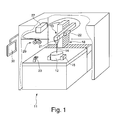
- FIG. 1 is a perspective view of a processing machine 11 for processing a workpiece 12 with a laser material processing beam 14 is shown.
- This processing machine 11 is, in particular, a laser processing machine, in which the workpiece 12 is processed with a laser material processing beam 14, in particular to carry out welding or welding.
- This processing machine 11 comprises a workpiece holder 16, which is preferably designed as a stationary mounting plate for clamping the workpiece 12.
- the workpiece holder 16 may also have at least one single or multi-axis guide to change the workpiece 12 in its position and position.
- a laser material processing device or laser material processing device 19 is provided, which positions a laser material processing head 21 of the laser material processing device 19 to the workpiece 12.
- the laser material processing jet device 19 is designed as a beam guide for guiding and / or shaping the laser material processing beam 14 with laser material processing head 21, which is fastened to the guide 18 and can be moved by this guide 18 into a processing position to the workpiece 12.
- the laser material processing device 19 may also be designed only as a laser material processing head 21 or may also comprise further components for forming, shaping and / or guiding the laser material processing beam 14. This is
- the adjustment of the processing position of the laser material processing beam 14 is preferably carried out by a manual control, which can be done for example via a manual control device 23 or a joystick, or an automatic control (NC control).
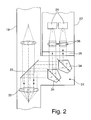
- FIG. 2 is a schematic sectional view of a laser material processing device 19 with a side arm 22 arranged thereon shown enlarged.
- This secondary arm 22 receives at least two signal detection devices 24, which detect a process image from a processing point on the workpiece 12.
- the process image from the laser material processing beam guidance of which only one lens 32, which collimates the process image, is shown by way of example, is coupled out of the laser material processing jet device 19 via a decoupling device 31.
- the decoupling device 31 comprises at least one beam splitter 33.
- the decoupling device 31 can comprise at least one beam guidance element 34, such as a prism or deflecting mirror and beam shaping elements, such as lenses, for example, which guide the process image to the signal detection devices 24.
- two pentaprisms are provided in order to divide the process image into two, so that in each case a part of the process image is in each case supplied to a signal detection device 24.
- an enlarging device 35 is preferably provided interchangeably. This magnification device 35 allows an optical magnification of the process image.
- the magnification device 35 may also be provided in the process image guidance of the laser material processing device 19.
- a collimation / focusing element 36 may preferably be provided in front of each beam detection device 24 in order to focus the enlarged process image onto the respective signal detection devices 24.
- FIG. 2 By way of example, the decoupling of the process image from the laser material processing jet device 19 into the secondary arm 22 is shown. Alternatively, such a decoupling can also take place from the laser material processing head 21.
- the signal detection devices 24 are preferably designed as CCD or CMOS cameras, which have an S-VGA resolution.
- the process image acquired by the two signal detection devices 24 is forwarded to a signal processing device 27, as in FIG FIG. 1 is shown.
- This Signalbearbeltungs pointed 27 includes u. a. a video multiplexer, which passes the signals to the camera and also controls the brightness and contrast of the captured images. At the same time a synchronization of the signals is detected on the video multiplexer, so that a 3D process visualization and the output of a 3D image from the processing point on at least one electronic binocular 29 and / or computer monitor 30 is made possible.
- individual process parameters and information can be faded into the three-dimensional image captured by the signal detection device 24 and displayed in the binocular in the three-dimensional image.
- a crosshair can be faded in to the target marking to allow the guidance of the cutting beam.
- different contrast colors can be faded in to ensure a sufficient visualization of the structures at the processing point with different materials.
- the transmission of the signals from the signal detection means 24 to the electronic binocular 29 or computer monitor 30 can take place via a signal line as well as wirelessly.
- the electronic binocular 29 consists of two screens, wherein in each screen, a separate image is displayed so that when viewed through the user, a three-dimensional image of the processing point is achieved.
- this screen may be to an OLED or LCD screen, especially with backlight act.
- Such electronic binoculars 29 are preferably provided on a carrying device, which can be fastened to the head of the user. Such an embodiment is referred to as a head mounted display.
- the carrying device may be equipped with an electronic binocular 29 and a laser protection, wherein the user can wear his individual visual aid undisturbed.
- the electronic binocular 29 is designed with a setting option for correcting vision.
- the electronic binoculars 29 is provided on the carrying device pivotable or fold away. This pivoting or folding function can also be provided in the attachment of the electronic binoculars 29 to the protective housing of the processing machine 11.
- a computer monitor 30 may be provided, which may be arranged on or in the vicinity of the processing machine 11 as well as remote from the processing machine 11. Moreover, it is possible that multiple carrying devices with electronic binoculars 29 and / or computer monitors 30 can be connected to the signal processing device 27, so that, for example, several viewers at the same time have the opportunity to monitor the processing process and the quality.
- a 3D Monltor be provided. This 3D monitor includes two signal inputs that allow the output of a 3D image.
Abstract
Description
Die Erfindung betrifft ein Verfahren zur Prozessvisualisierung einer Bearbeitung eines Werkstückes sowie eine Bearbeitungsmaschine mit einer Prozessvisualisierung zur Bearbeitung eines Werkstückes.The invention relates to a method for process visualization of a machining of a workpiece and to a machine tool with a process visualization for machining a workpiece.
Zur Bearbeitung von kleineren Werkstücken mit einem Schweißstrahl, insbesondere Laserstrahl, ist bereits eine Bearbeitungsmaschine mit der Bezeichnung PowerWeld der Firma Trumpf Laser GmbH + Co. KG bekannt, bei der ein abgeschlossener Arbeitsraum vorgesehen ist. In diesem abgeschlossen Arbeitsraum ist eine luftgelagerte Arbeitsplatte zur Aufnahme eines Werkstückes vorgesehen, wobei diese luftgelagerte Arbeitsplatte ein einfaches Positionieren des Werkstückes ermöglicht, um das Werkstück gegenüber einer ortsfesten Schweißstrahleinrichtung zum Arbeitsraum zu bewegen und eine Bearbeitung des Werkstückes zu ermöglichen, Die Positionierung des Werkstückes wird angesteuert. Zur Beobachtung des Bearbeitungsprozesses, bei dem ein durch die Schweißstrahleinrichtung geführter Schweißstrahl auf das Werkstück auftritt, ist an der ortsfesten Schweißstrahleinrichtung ein Stereomikroskop vorgesehen, welches einen Einblick in den abgeschlossenen Arbeitsraum zur Bearbeitungsstelle ermöglicht.For processing of smaller workpieces with a welding beam, in particular laser beam, a processing machine with the name PowerWeld of Trumpf Laser GmbH + Co. KG is already known, in which a closed working space is provided. In this completed workspace an air bearing worktop for receiving a workpiece is provided, said air bearing worktop allows easy positioning of the workpiece to the workpiece relative to a stationary welding device for Move working space and allow machining of the workpiece, the positioning of the workpiece is controlled. To observe the machining process, in which a guided through the welding beam welding beam occurs on the workpiece, a stereomicroscope is provided on the stationary welding device, which allows insight into the closed working space to the processing point.
Diese Bearbeitungsmaschine ermöglicht eine präzise Bearbeitung der Werkstücke. Aufgrund der ortsfesten Anordnung des Stereomikroskopes als auch dem abgeschlossenen Arbeitsraum sowie der erforderlichen Verschiebbewegung des Werkstückes zu dessen Bearbeitung ist der Einsatz einer solchen Bearbeitungsmaschine auf darauf abgestimmte Bearbeitungsfälle begrenzt. Zudem weist ein solcher Arbeitsplatz ergonomische Nachteile für den Benutzer auf.This machine allows a precise machining of the workpieces. Due to the stationary arrangement of the stereomicroscope as well as the closed working space and the required displacement movement of the workpiece for its processing, the use of such a processing machine is limited to coordinated processing cases. In addition, such a workplace has ergonomic disadvantages for the user.
Aus der
Eine solche Handbearbeitungsmaschine weist den Nachteil auf, dass die Bearbeitung unpräzise ist, da der Abstand zwischen der Bearbeitungsstelle des Werkstückes und dem Schneidkopf des Handgerätes aufgrund der Handführung nicht konstant gehalten werden kann. Darüber hinaus ist die Visualisierung der Bearbeitungsstelle über die CCD-Kamera durch die zumeist unruhige Handführung beeinträchtigt und somit über Bearbeitungsbereiche unscharf. Darüber hinaus kann durch die CCD-Kamera nur eine zweidimensionale Abbildung der Bearbeitungsstelle erfasst werden. Des Weiteren ist die Flexibilität der Bearbeitung von Werkstücken durch die Leistung solcher Handgeräte sehr beschränkt.Such a hand-working machine has the disadvantage that the machining is imprecise, since the distance between the machining point of the workpiece and the cutting head of the hand-held device can not be kept constant due to the manual guidance. In addition, the visualization of the processing point on the CCD camera is affected by the mostly restless hand guidance and thus blurred about editing areas. In addition, only a two-dimensional image of the processing point can be detected by the CCD camera. Furthermore, the flexibility of machining workpieces is very limited by the performance of such handsets.
Der Erfindung liegt deshalb die Aufgabe zugrunde, ein Verfahren zur Prozessvisualisierung einer Bearbeitung eines Werkstückes durch eine Lasermaterialbearbeitung sowie eine Bearbeitungsmaschine mit einer Prozessvisualisierung zur Durchführung der Lasermaterialbearbeitung zu schaffen, bei der eine dreidimensionale Prozessvisuallsierung der Bearbeitungsstelle sowie unabhängig davon eine flexible Bearbeitung ermöglicht ist.The invention is therefore based on the object to provide a method for process visualization of a machining of a workpiece by a laser material processing and a processing machine with a process visualization for performing the laser material processing, in which a three-dimensional Prozeßvisuallsierung the processing site and regardless of flexible processing is possible.
Diese Aufgabe wird erfindungsgemäß durch ein Verfahren gemäß den Merkmalen des Anspruchs 1 gelöst. Durch eine Entkopplung der Signalerfassungseinrichtung von einer Ausgabe der erfassten Prozessbilder der Bearbeitungsstelle durch zumindest ein elektronisches Binokular oder einen Computerbildschirm wird ermöglicht, dass insbesondere bei einer Bearbeitung des Werkstücks mit einem Laserstrahlein Materialbearbeitungskopf zur Führung des Bearbeitungsstrahles in allen Freiheitsgraden bewegt werden kann, ohne dass der Bediener seinen Kopf zur Beobachtung der Bearbeitungsstelle nachführen muss. Dadurch können alle erforderlichen Vorschubbewegungen des Materialbearbeitungskopfes, insbesondere bei der 3D-Bearbeitung, durchgeführt werden, so dass ein werkstückunabhängiger Aufbau der Bearbeitungsmaschine ermöglicht ist. Durch die zumindest eine ein- oder mehrachsige Führung des Materialbearbeitungskopfes, der manuell und/oder über eine NC-Steuerung ansteuerbar ist, und durch zumindest zwei Signalerfassungseinrichtungen wird erzielt, dass eine präzises Erfassung eines Prozessbildes an der Bearbeitungsstelle ermöglicht ist. Ein unruhiges und/oder unscharfes Prozessbild, wie dies beispielsweise bei einer handgeführten Schweißstrahleinrichtung der Fall wäre, kann zudem durch die zumindest eine ein- oder mehrachsige Führung eliminiert werden. Darüber hinaus weist das erfindungsgemäße Verfahren durch die Erfassung eines Prozessbildes mit zumindest zwei Signalerfassungseinrichtungen den Vorteil auf, dass ein dreidimensionales Prozessbild erzeugt und auf zumindest einem elektronischen Binokular mit zwei Bildschirmen oder an zumindest einem Computermonitor, insbesondere einem 3D-Monitor, dargestellt wird. Durch die elektronische Übertragung des Prozessbildes können des Weiteren Komponenten wie Blendschutz, Bildumkehrung, Binokulartubus, Laserfilter entfallen, wodurch ein einfacher Aufbau zur Prozessvisualisierung ermöglicht ist. Die Signalerfassungseinrichtungen können unmittelbar von der Bearbeitungsstelle Prozessbilder erfassen und werden bevorzugt zusammen mit dem Materialbearbeitungskopf verfahren.This object is achieved by a method according to the features of claim 1. By decoupling the signal detection device from an output of the acquired process images of the processing point by at least one electronic binocular or a computer screen is made possible that in particular when processing the workpiece with a laser beam in a material processing head for guiding the processing beam in all degrees of freedom can be moved without the operator must follow his head to observe the processing point. As a result, all the necessary feed movements of the material processing head, in particular in the case of 3D processing, can be carried out, so that a workpiece-independent construction of the processing machine is made possible. By at least one single or multi-axis guidance of the material processing head, which can be controlled manually and / or via an NC control, and by at least two signal detection devices is achieved that a precise detection of a process image is made possible at the processing site. A restless and / or blurred process image, as would be the case for example in a hand-held welding device, can also be eliminated by the at least one single or multi-axis guidance. In addition, the method according to the invention has the advantage that a three-dimensional process image is generated and displayed on at least one electronic binocular with two screens or on at least one computer monitor, in particular a 3D monitor, by the acquisition of a process image with at least two signal detection devices. Due to the electronic transmission of the process image, components such as anti-dazzle protection, image inversion, binocular tube and laser filter can also be dispensed with, resulting in a simple structure for process visualization is possible. The signal detection devices can acquire process images directly from the processing point and are preferably moved together with the material processing head.
Nach einer bevorzugt Ausgestaltung des Verfahrens ist vorgesehen, dass das zumindest eine übertragene Prozessbild aus dem Materialbearbeitungskopf ausgekoppelt wird. Diese Anordnung weist den Vorteil auf, dass beispielsweise eine direkte Anbindung einer Materialbearbeitungsstrahlzuführung über einen Lichtleiter an den Materialbearbeitungskopf ermöglicht ist. Dies ermöglicht auch, dass beispielsweise der Materialbearbeitungskopf an einem Roboter als Handhabungsmedium vorgesehen sein kann.According to a preferred embodiment of the method, it is provided that the at least one transferred process image is coupled out of the material processing head. This arrangement has the advantage that, for example, a direct connection of a material processing beam supply via a light guide to the material processing head is made possible. This also makes it possible, for example, for the material processing head to be provided on a robot as a handling medium.
Nach einer alternativen Ausgestaltung des Verfahrens ist vorgesehen, dass das zumindest eine übertragene Prozessbild von dem Materialbearbeitungskopf in eine Materialbearbeitungsstrahleinrichtung weitergeleitet und aus der Materialbearbeitungsstrahleinrichtung ausgekoppelt wird. Diese Auskopplung weist den Vorteil auf, dass bestehende Materialbearbeltungsstrahleinrichtungen eingesetzt werden können, die bezüglich einer Auskoppelstelle modifiziert oder nachgerüstet werden. Die Auskopplung des zumindest einen Prozessbildes aus dem Materialbearbeitungskopf oder aus der Materialbearbeitungsstrahleinrichtung weist darüber hinaus den Vorteil auf, dass keine Beeinträchtigungen zur Erfassung der Signale während einer Materlalbearbeitung gegeben sind.According to an alternative embodiment of the method, it is provided that the at least one transferred process image is forwarded from the material-processing head into a material-processing jet device and decoupled from the material-processing jet device. This decoupling has the advantage that existing Materialbearbeltungsstrahl facilities can be used, which are modified or retrofitted with respect to a decoupling point. The decoupling of the at least one process image from the material processing head or from the material processing radiating device furthermore has the advantage that there are no impairments for the detection of the signals during a material processing.
Nach einer vorteilhaften Ausgestaltung des Verfahrens ist vorgesehen, dass die durch die Signalerfassungseinrichtungen erfassten Signale eines Prozessbildes überlagert und als dreidimensionale Abbildung aufbereitet werden. Bevorzugt ist eine linke und eine rechte Signalerfassungseinrichtung vorgesehen, um die dreidimensionale Abbildung beispielsweise in einem linken und rechten Bildschirm des elektronischen Binokulars auszugeben. Dadurch wird ermöglicht, dass für den Benutzer eine wirklichkeitsgetreue Darstellung der Bearbeitungsstelle übermittelt wird, ohne dass der Benutzer selbst unmittelbar einen Einblick auf die Bearbeitungsstelle hat oder braucht. Dadurch kann der Benutzer eine exakte und präzise Bearbeitung des Werkstückes, insbesondere auch von sehr feinen und filigranen Strukturen ansteuern und durchführen. Der Arbeitsplatz des Benutzers kann zudem für diesen ergonomisch günstig eingerichtet werden.According to an advantageous embodiment of the method, it is provided that the signals detected by the signal detection devices are superimposed on a process image and processed as a three-dimensional image. Preferably, a left and a right signal detection means are provided to output the three-dimensional image, for example, in a left and right screen of the electronic binocular. This makes it possible for the user to be given a true-to-life representation of the processing site without the user himself having or needing immediate insight into the processing site. This allows the user an exact and precise machining of the workpiece, especially from very control and execute fine and filigree structures. The user's workplace can also be set up ergonomically for this.
Nach einer weiteren vorteilhaften Ausgestaltung der Erfindung ist vorgesehen, dass durch die Signalbearbeitungseinrichtung zumindest ein Fadenkreuz, ein oder mehrere Bearbeitungsparameter oder Zustandsmeldungen zur Bearbeitung des Werkstückes in das zumindest eine erfasste und aufbereitete Prozessbild eingeblendet oder diesem überlagert werden. Folglich werden dem Bediener zusätzliche Informationen zur Verfügung gestellt, damit dieser gleichzeitig während einer Überwachung der Bearbeitungsstelle die erforderlichen Parameter erfassen und berücksichtigen kann, ohne den Blick von der Bearbeitungsstelle bzw. dem elektronischen Binokular oder Computermonitor zu entfernen. Das Fadenkreuz dient beispielsweise zur Einstellung und Positionierung des Laserstrahls zum Auftreffpunkt des Laserbearbeitungsstrahles. Durch die Bearbeitungsparameter kann die Bearbeitungsgeschwindigkeit, die Spurbreite und dergleichen überwacht werden, so dass der Bediener zumindest über die wesentlichen Informationen in Echtzeit informiert wird.According to a further advantageous embodiment of the invention, it is provided that at least one reticle, one or more processing parameters or status messages for processing the workpiece are superimposed or superimposed on the at least one detected and processed process image by the signal processing device. As a result, additional information is provided to the operator to allow him to simultaneously capture and account for the required parameters during monitoring of the processing station without taking his eyes off the processing station or the electronic binocular or computer monitor. The crosshair is used for example for setting and positioning of the laser beam to the point of impact of the laser processing beam. By the processing parameters, the processing speed, the track width and the like can be monitored, so that the operator is informed at least about the essential information in real time.
Nach einer weiteren vorteilhaften Ausgestaltung des Verfahrens kann das durch die Signalerfassungseinrichtungen erfasste und durch die Signalbearbeltungseinrichtung aufbereitete Prozessbild zur Bildverarbeitung genutzt werden, um durch die dreidimensionale Erfassung des Werkstücks die Bearbeitungsbahn automatisch oder manuell zu teachen, die geteachte Bahn gemäß der aktuellen Lage des Werkstücks zu verschieben und/oder zu verdrehen oder aber auch über eine dynamische Bildverarbeitung Prozessüberwachungsfunktionen wie Nahtverfolgung zu integrieren.According to a further advantageous refinement of the method, the process image captured by the signal detection devices and processed by the signal processing device can be used to automatically or manually teach the processing path by the three-dimensional detection of the workpiece, to move the taught path according to the current position of the workpiece and / or to twist or integrate via a dynamic image processing process monitoring functions such as seam tracking.
Nach einer weiteren vorteilhaften Ausgestaltung des Verfahrens ist vorgesehen, dass die Signalerfassungseinrlchtung aus einer Kamera besteht, welche eine Auflösung der Strukturen von bis zu 1 µm ermöglicht. Eine Auflösung, beispielsweise von ca. 800 x 600 Pixel oder mehr, ermöglicht hochpräzise Bilder von der Bearbeitungsstelle auf dem zumindest einen elektronischen Binokular oder dem Computermonitor dargestellt werden können.According to a further advantageous embodiment of the method, it is provided that the signal detection device consists of a camera which enables a resolution of the structures of up to 1 μm. A resolution, for example of about 800 x 600 pixels or more, allows high-precision images of the processing point on the at least an electronic binocular or the computer monitor can be displayed.
Nach einer weiteren vorteilhaften Ausgestaltung des Verfahrens ist vorgesehen, dass den Signalerfassungseinrichtungen zumindest eine Vergrößerungseinrichtung vorgeschaltet wird. Dadurch können detaillierte Betrachtungen vorgenommen werden, ohne ein digitales Zoom einzusetzen, so dass eine hohe Bildqualität erzielt wird.According to a further advantageous embodiment of the method, it is provided that at least one enlargement device is connected upstream of the signal detection devices. As a result, detailed observations can be made without using a digital zoom, so that a high image quality is achieved.
Des Weiteren ist bevorzugt vorgesehen, dass die Aufbereitung der Signale, welche den Signalbearbeitungsprozess bilden, durch einen Video-Multiplexer durchgeführt wird. Dadurch lassen sich durch die Synchronisation der Signale Abbildungen für den Benutzer in Echtzeit erzeugen. Bevorzugt ist der Video-Multiplexer Bestandteil der Steuerung, so dass sämtliche Prozesse über eine gemeinsame Steuerung ablaufen können.Furthermore, it is preferably provided that the conditioning of the signals which form the signal processing process is performed by a video multiplexer. This allows the synchronization of the signals to generate images for the user in real time. Preferably, the video multiplexer is part of the controller, so that all processes can run on a common control.
Die der Erfindung zugrundeliegende Aufgabe wird des Weiteren durch eine Bearbeitungsmaschine gelöst, bei welcher die zumindest eine Bearbeitungsposition eines Materialbearbeitungsstrahles, insbesondere eines Laserstrahles, durch Verfahren eines Materialbearbeitungskopfes zum Werkstück positionierbar ist, wobei der Materialbearbeitungskopf manuell und/oder durch eine NC-Steuerung verfahrbar ist. Von der Bearbeitungsposition wird durch zumindest zwei Signalerfassungseinrichtungen jeweils zumindest ein Prozessbild erfasst und für die Aufbereitung der Signale an eine Signalbearbeitungseinrichtung weitergeleitet, um das aufbereitete Prozessbild in zumindest einem elektronischen Binokular mit zwei Bildschirmen oder zumindest einem Computermonitor darzustellen. Dadurch wird eine Materialbearbeitung ermöglicht, bei der die Beobachtungsposition unabhängig von der Position des Materialbearbeitungskopfes zum Werkstück ist. Folglich können auch schwerere Werkstücke handwerklich bearbeitet werden, indem lediglich ein Verfahren des Materialbearbeitungskopfes erforderlich ist. Dieser Materialbearbeitungskopf kann in allen Freiheitsgraden bewegt werden. Die Signalerfassungseinrichtungen können unmittelbar an dem Bearbeitungskopf vorgesehen sein, so dass diese ein Prozessbild direkt von der Bearbeitungsstelle erfassen. Durch einen solchen Aufbau kann des Weiteren die Umhausung der Bearbeitungsmaschine stark vereinfacht werden. Durch die elektronische Übertragung des Prozessbildes können der Blendschutz und die Bildumkehrung wegfallen, wodurch der Aufbau des Arbeitsraumes als auch die Prozessvisualisierung vereinfacht werden. Gleichzeitig kann eine höhere Ergonomie durch die Entkopplung des Einblicks zur Bearbeitungsstelle ermöglicht sein.The object underlying the invention is further achieved by a processing machine in which the at least one processing position of a material processing beam, in particular a laser beam can be positioned by moving a material processing head to the workpiece, wherein the material processing head is manually and / or moved by an NC control. At least one process image is detected by the processing position by at least two signal detection devices and forwarded to a signal processing device for processing the signals in order to display the processed process image in at least one electronic binocular having two screens or at least one computer monitor. This allows material processing in which the observation position is independent of the position of the material processing head to the workpiece. As a result, even heavier workpieces can be artificially machined merely by requiring a process of the material processing head. This material processing head can be moved in all degrees of freedom. The signal detection devices can be provided directly on the machining head so that they capture a process image directly from the machining point. By such a structure, furthermore, the housing the processing machine are greatly simplified. Due to the electronic transmission of the process image, the glare protection and the image inversion can be eliminated, which simplifies the construction of the workspace as well as the process visualization. At the same time a higher ergonomics can be made possible by the decoupling of the insight to the processing point.
Nach einer bevorzugt Ausführungsform der Bearbeitungsmaschine ist vorgesehen, dass am Materialbearbeitungskopf eine Auskoppeleinrichtung vorgesehen ist, durch die das zumindest eine Prozessbild zur Weiterleitung an die Signalerfassungseinrichtungen aus dem Materialbearbeitungskopf auskoppelbar ist. Durch eine solche an dem Materialbearbeitungskopf angeordnete Auskoppeleinrichtung kann eine geschützte Auskopplung erzielt werden. Bevorzugt ist die Auskoppeleinrichtung zur platzsparenden Anordnung im Materialbearbeitungskopf zumindest teilweise eingebunden.According to a preferred embodiment of the processing machine, it is provided that a decoupling device is provided on the material processing head, by means of which the at least one process image can be decoupled from the material processing head for transmission to the signal detection devices. By means of such a decoupling device arranged on the material processing head, a protected extraction can be achieved. Preferably, the decoupling device for space-saving arrangement in the material processing head is at least partially involved.
Nach einer weiteren alternativen Ausgestaltung der Bearbeitungsmaschine ist vorgesehen, dass der Materialbearbeitungskopf an einer Materialbearbeitungsstrahleinrichtung vorgesehen und dass das zumindest eine an die Materialbearbeitungseinrichtung weitergeleitete Prozessbild aus der Materialbearbeitungseinrichtung auskoppelbar ist. Dies ermöglicht, dass die Signalerfassungseinrichtungen entfernt vom Materialbearbeitungskopf im geschützten Bereich vorgesehen sind.According to a further alternative embodiment of the processing machine, it is provided that the material processing head is provided on a material-processing jet device and that the at least one process image forwarded to the material processing device can be decoupled from the material processing device. This allows the signal detectors to be located away from the material processing head in the protected area.
Bevorzugt ist an der Materialbearbeltungseinrichtung eine Auskoppeleinrichtung vorgesehen, die das Prozessbild aus der Materialbearbeitungseinrichtung auskoppelt und den Signalerfassungseinrichtungen zuführt. Solche Auskoppeleinrichtungen können auch nachrüstbar vorgesehen sein, um eine bestehende Bearbeitungsmaschine umzurüsten.Preferably, a decoupling device is provided on the Materialbearbeltungseinrichtung, which decouples the process image from the material processing device and the signal detection means supplies. Such decoupling devices can also be provided retrofittable to convert an existing processing machine.
Die Auskoppeleinrichtung umfasst gemäß einer bevorzugten Ausgestaltung zumindest einen Strahlteiler, um das in dem Materialbearbeitungskopf oder der Materialbearbeitungseinrichtung geführte Prozessbild auszukoppeln.The decoupling device comprises according to a preferred embodiment, at least one beam splitter to decouple the guided in the material processing head or the material processing device process image.
Nach einer vorteilhaften Ausgestaltung der Bearbeitungsmaschine ist vorgesehen, dass das zumindest eine elektronische Binokular oder der zumindest eine Computermonitor unabhängig von der Materialbearbeitungsstrahleinrichtung positionierbar sind. Dadurch ist eine Erhöhung in der Flexibilität bei der Überwachung dieser Bearbeitungsmaschine gegeben. Der Benutzer kann frei über die Anordnung des elektronischen Binokulars oder des Bildschirmes aufgrund der elektronischen Datenübertragung des aufbereiteten Prozessbildes entscheiden.According to an advantageous embodiment of the processing machine, it is provided that the at least one electronic binocular or the at least one computer monitor can be positioned independently of the material-processing jet device. This provides an increase in the flexibility in monitoring this processing machine. The user can freely decide on the arrangement of the electronic binocular or the screen due to the electronic data transmission of the processed process image.
Durch die unabhängige Positionierung des elektronischen Binokulars und/oder der Computermonitore kann auch ermöglicht sein, dass getrennt und entfernt von der Bearbeitungsmaschine Computermonitore zur zusätzlichen oder separaten Überwachung der Laserbearbeitung vorgesehen sein können.Due to the independent positioning of the electronic binocular and / or the computer monitors can also be possible that separate and remote from the processing machine computer monitors for additional or separate monitoring of the laser processing can be provided.
Nach einer bevorzugten Ausführungsform der Bearbeitungsmaschine ist vorgesehen, dass die Signalerfassungseinrichtung als Kamera, insbesondere als CCD- oder CMOS-Kamera ausgebildet ist, welche vorzugsweise mit zumindest einer S-VGA-Auflösung arbeitet. Dadurch können feine Strukturen von weniger als 5 µm deutlich aufgelöst werden.According to a preferred embodiment of the processing machine is provided that the signal detection device is designed as a camera, in particular as a CCD or CMOS camera, which preferably operates with at least one S-VGA resolution. As a result, fine structures of less than 5 microns can be clearly resolved.
Das elektronische Binokular ist gemäß einer ersten Ausführungsform an dem Schutzgehäuse der Bearbeitungsmaschine befestigbar. Dies ermöglicht, dass für den Benutzer kurze Wege gegeben sind, so dass dieser unmittelbar nach dem Bestücken der Bearbeitungsmaschine mit einem neuen Werkstück den nachfolgend gestarteten Bearbeitungsprozess beobachten kann.The electronic binocular is fastened to the protective housing of the processing machine according to a first embodiment. This makes it possible for the user to be given short paths, so that the latter can observe the subsequently started machining process immediately after loading the processing machine with a new workpiece.
Nach einer alternativen Ausgestaltung der Erfindung ist vorgesehen, dass das elektronische Binokular als eine am Kopf des Betrachters anbringbare Tragevorrichtung mit zwei Bildschirmen ausgebildet ist. Solche sogenannten Head Mounted Displays (HMD) ermöglichen, dass der Benutzer unabhängig von der Bearbeitungsmaschine sich bewegen und dennoch den Bearbeitungsprozess überwachen kann.According to an alternative embodiment of the invention it is provided that the electronic binocular is designed as an attachable to the head of the viewer carrying device with two screens. Such so-called head mounted displays (HMD) allow the user to move independently of the machine tool and still monitor the machining process.
Das elektronische Binokular ist bevorzugt an der Tragevorrichtung derart befestigt, dass dieses im Abstand zur individuellen Sehhilfe des Benutzers einstellbar ist. Dadurch ist ein universeller Einsatz der Tragevorrichtung ermöglicht, ohne dass der Benutzer seine individuelle Sehhilfe absetzen muss. Alternativ kann vorgesehen sein, dass das elektronische Binokular eine Einstellmöglichkeit auf die individuelle Sehstärke des Benutzers ermöglicht.The electronic binocular is preferably attached to the carrying device in such a way that it is adjustable at a distance from the user's individual visual aid. This allows a universal use of the carrying device, without the user having to sell his individual visual aid. Alternatively it can be provided that the electronic binocular allows adjustment to the individual vision of the user.
Bei der Ausgestaltung des elektronischen Binokulars als Head Mounted Display ist bevorzugt vorgesehen, dass vor dem elektronischen Binokular und der Sehhilfe oder zwischen dem elektronischen Binokular und der Sehhilfe eine Laserschutzvorrichtung vorgesehen ist. Beispielsweise kann eine solche Laserschutzvorrichtung als Korbversion auf dem Head Mounted Display montiert werden. Dadurch ist zum einen die Lasersicherheit gegeben und zum anderen die Vereinfachung beim Aufbau des Schutzgehäuses der Bearbeitungsmaschine.In the embodiment of the electronic binocular as a head mounted display is preferably provided that a laser protection device is provided in front of the electronic binocular and the visual aid or between the electronic binocular and the visual aid. For example, such a laser protection device can be mounted as a basket version on the head mounted display. As a result, on the one hand the laser safety is given and on the other hand, the simplification in the construction of the protective housing of the processing machine.
Nach einer weiteren vorteilhaften Ausgestaltung der Bearbeitungsmaschine ist vorgesehen, dass das elektronische Binokular oder der Computermonitor aus dem Sichtfeld des Betrachters herausschwenkbar oder herausklappbar sind. Analoges gilt auch für einen SD-Monitor. Beispielsweise kann bei der Anordnung des elektronischen Binokulars oder Computermonitors an dem Gehäuse durch die klappbare Anordnung ermöglicht sein, dass der Benutzer seine Position zur Bearbeitungsmaschine beibehält und einerseits die Betrachtung über das elektronische Binokular oder den Monitor vornehmen kann und andererseits nach der Schwenkbewegung einen unmittelbaren Einblick auf die Bearbeitungsstelle hat. Bei der Anordnung des elektronischen Binokulars in einer Tragevorrichtung als Head Mounted Display kann der Benutzer durch einfaches Klappen weitere Tätigkeiten durchführen, ohne die gesamte Tragevorrichtung abzusetzen. Besonders bevorzugt ist ein elektronisches Binokular das gleichzeitig oder abwechselnd eine Prozessvisualisierung und/oder Betrachtung der Umgebung ermöglicht.According to a further advantageous embodiment of the processing machine is provided that the electronic binocular or the computer monitor from the field of view of the viewer can be swung out or folded out. The same applies to an SD monitor. For example, in the arrangement of the electronic binocular or computer monitor on the housing by the hinged arrangement may be possible that the user maintains its position to the machine and on the one hand make the viewing through the electronic binocular or the monitor and on the other hand after the pivotal movement on a direct view the processing point has. In the arrangement of the electronic binoculars in a carrying device as a head mounted display, the user can perform other activities by simply flapping without dropping the entire carrying device. Particularly preferred is an electronic binocular which simultaneously or alternately enables process visualization and / or viewing of the environment.
Die Erfindung sowie weitere vorteilhafte Ausführungsformen und Weiterbildungen derselben werden im Folgenden anhand dem in der Zeichnung dargestellten Beispiel näher beschrieben und erläutert. Die der Beschreibung und der Zeichnung zu entnehmenden Merkmale können einzeln für sich oder zu mehreren in beliebiger Kombination erfindungsgemäß angewandt werden. Es zeigen:
- Figur 1
- eine perspektivische Darstellung einer erfindungsgemäßen Bearbeitungsmaschine und
- Figur 2
- eine schematische Schnittdarstellung einer Lasermaterialbearbeitungsstrahleinrichtung mit daran angeordneten Signalerfassungselnrichtungen.
- FIG. 1
- a perspective view of a processing machine according to the invention and
- FIG. 2
- a schematic sectional view of a laser material processing radiation device arranged thereon Signalalerfassungselnrichtungen.
In
In
In
Die Signalerfassungseinrichtungen 24 sind bevorzugt als CCD- oder CMOS-Kameras ausgebildet, welche eine S-VGA-Auflösung aufweisen. Das durch die beiden Signalerfassungseinrichtungen 24 erfasste Prozessbild wird an eine Signalbearbeitungseinrichtung 27 weitergeleitet, wie in
Diese Signalbearbeltungseinrichtung 27 umfasst u. a. einen Video-Multiplexer, der die Signale an die Kamera weitergibt und zudem die Helligkeit und den Kontrast der erfassten Bilder steuert. Gleichzeitig wird auf dem Video-Multiplexer eine Synchronisation der Signale erfasst, so dass eine 3D-Prozessvisualisierung und die Ausgabe eines 3D-Bildes von der Bearbeitungsstelle auf zumindest einem elektronischen Binokular 29 und/oder Computermonitor 30 ermöglicht ist.This
Durch die Signalbearbeitungseinrichtung 27 können einzelne Prozessparameter und Informationen in das durch die Signalerfassungseinrichtung 24 erfasste dreidimensionale Bild eingeblendet und im Binokular im dreidimensionalen Bild dargestellt werden. Beispielsweise kann ein Fadenkreuz zur Zielmarkierung eingeblendet werden, um die Zielführung des Schneidstrahls zu ermöglichen. Des Weiteren können unterschiedliche Kontrastfarben eingeblendet werden, um eine hinreichende visualisierung der Strukturen an der Bearbeitungsstelle bei unterschiedlichen Werkstoffen zu gewährleisten.By means of the
Die Übertragung der Signale von den Signalerfassungseinrichtungen 24 zum elektronischen Binokular 29 oder Computermonitor 30 kann über eine Signalleitung als auch kabellos erfolgen.The transmission of the signals from the signal detection means 24 to the electronic binocular 29 or computer monitor 30 can take place via a signal line as well as wirelessly.
Das elektronische Binokular 29 besteht aus zwei Bildschirmen, wobei In jedem Bildschirm ein separates Bild eingeblendet wird, so dass bei dessen Betrachtung über den Benutzer eine dreidimensionale Abbildung der Bearbeitungsstelle erzielt wird. Bei diesem Bildschirm kann es sich beispielsweise um einen OLED- oder LCD-Bildschirm, insbesondere mit Hintergrundbeleuchtung, handeln.The electronic binocular 29 consists of two screens, wherein in each screen, a separate image is displayed so that when viewed through the user, a three-dimensional image of the processing point is achieved. For example, this screen may be to an OLED or LCD screen, especially with backlight act.
Solche elektronischen Binokulare 29 sind bevorzugt an einer Tragevorrichtung vorgesehen, die am Kopf des Benutzers befestigbar ist. Eine solche Ausgestaltung wird als Head Mounted Display bezeichnet. Dabei können folgende Ausgestaltungen bei den vorliegenden Einsatzzwecken vorgesehen sein. Beispielsweise kann die Tragevorrichtung mit einem elektronischen Binokular 29 und einem Laserschutz ausgestattet sein, wobei der Benutzer seine individuelle Sehhilfe unbeeinträchtigt tragen kann. Alternativ kann vorgesehen sein, dass das elektronische Binokular 29 mit einer Einstellmöglichkeit zur Sehstärkenkorrektur ausgebildet ist.Such
Bevorzugt ist das elektronische Binokular 29 an der Tragevorrichtung schwenkbar oder wegklappbar vorgesehen. Diese Schwenk- oder Klappfunktion kann auch bei der Befestigung des elektronischen Binokulars 29 am Schutzgehäuse der Bearbeitungsmaschine 11 vorgesehen sein.Preferably, the
Alternativ zur Darstellung der Bearbeitungsstelle über das elektronische Binokular 29 oder zusätzlich zum Binokular 29 kann ein Computermonitor 30 vorgesehen sein, der an oder in der Nähe der Bearbeitungsmaschine 11 als auch entfernt zu Bearbeitungsmaschine 11 angeordnet sein kann. Darüber hinaus ist ermöglicht, dass mehrere Tragevorrichtungen mit elektronischen Binokularen 29 und/oder Computermonitore 30 an die Signalbearbeitungseinrichtung 27 anschließbar sind, so dass beispielsweise mehrere Betrachter gleichzeitig die Möglichkeit haben, den Bearbeitungsprozess und die Qualität zu überwachen. Alternativ oder zusätzlich kann auch ein 3D-Monltor vorgesehen sein. Dieser 3D-Monitor umfasst zwei Signaleingänge, die die Ausgabe eines 3D-Bildes ermöglichen.As an alternative to the illustration of the processing point via the electronic binocular 29 or in addition to the binocular 29, a
Claims (22)
dadurch gekennzeichnet,
characterized,
Priority Applications (1)
| Application Number | Priority Date | Filing Date | Title |
|---|---|---|---|
| EP07023148A EP2065117A1 (en) | 2007-11-29 | 2007-11-29 | Method and machine tool for process visualisation of machining process of a workpiece |
Applications Claiming Priority (1)
| Application Number | Priority Date | Filing Date | Title |
|---|---|---|---|
| EP07023148A EP2065117A1 (en) | 2007-11-29 | 2007-11-29 | Method and machine tool for process visualisation of machining process of a workpiece |
Publications (1)
| Publication Number | Publication Date |
|---|---|
| EP2065117A1 true EP2065117A1 (en) | 2009-06-03 |
Family
ID=39267895
Family Applications (1)
| Application Number | Title | Priority Date | Filing Date |
|---|---|---|---|
| EP07023148A Withdrawn EP2065117A1 (en) | 2007-11-29 | 2007-11-29 | Method and machine tool for process visualisation of machining process of a workpiece |
Country Status (1)
| Country | Link |
|---|---|
| EP (1) | EP2065117A1 (en) |
Cited By (6)
| Publication number | Priority date | Publication date | Assignee | Title |
|---|---|---|---|---|
| DE102012207835A1 (en) * | 2011-05-11 | 2012-11-15 | Arges Gmbh | Method and device for monitoring a laser processing process |
| CN104117852A (en) * | 2014-07-02 | 2014-10-29 | 苏州市辰希特钣金制品有限公司 | Punching device with laser punching device |
| DE102013210078A1 (en) * | 2013-05-29 | 2014-12-04 | Trumpf Werkzeugmaschinen Gmbh + Co. Kg | Apparatus and method for determining the focus position of a high energy beam and computer program product |
| DE102013216169A1 (en) * | 2013-08-14 | 2015-02-19 | Bayerische Motoren Werke Aktiengesellschaft | Device for reworking defects in component production |
| CN109739018A (en) * | 2019-03-25 | 2019-05-10 | 南京恒融光电技术有限公司 | A kind of crack is to focusing microscope |
| CN111790985A (en) * | 2020-07-20 | 2020-10-20 | 兰州城市学院 | Novel laser welding device |
Citations (5)
| Publication number | Priority date | Publication date | Assignee | Title |
|---|---|---|---|---|
| US4559555A (en) * | 1982-02-24 | 1985-12-17 | Arnold Schoolman | Stereoscopic remote viewing system |
| FR2571866A1 (en) * | 1984-10-12 | 1986-04-18 | Gec Avionics | METHOD AND APPARATUS FOR POSITION INDICATORS, IN PARTICULAR FOR ROBOT. |
| JPH09300088A (en) * | 1996-05-15 | 1997-11-25 | Amada Co Ltd | Handy type laser beam machine |
| US6211484B1 (en) * | 1996-01-05 | 2001-04-03 | Lazare Kaplan International, Inc. | Laser making system and certificate for a gemstone |
| DE102005024085A1 (en) * | 2005-05-25 | 2006-11-30 | Precitec Kg | Laser processing step e.g. laser welding/cutting process, monitoring device for workpiece, has radiation-sensitive receiver e.g. photodiode, and camera e.g. CCD image sensor, that simultaneously supply output signals to evaluation circuit |
-
2007
- 2007-11-29 EP EP07023148A patent/EP2065117A1/en not_active Withdrawn
Patent Citations (5)
| Publication number | Priority date | Publication date | Assignee | Title |
|---|---|---|---|---|
| US4559555A (en) * | 1982-02-24 | 1985-12-17 | Arnold Schoolman | Stereoscopic remote viewing system |
| FR2571866A1 (en) * | 1984-10-12 | 1986-04-18 | Gec Avionics | METHOD AND APPARATUS FOR POSITION INDICATORS, IN PARTICULAR FOR ROBOT. |
| US6211484B1 (en) * | 1996-01-05 | 2001-04-03 | Lazare Kaplan International, Inc. | Laser making system and certificate for a gemstone |
| JPH09300088A (en) * | 1996-05-15 | 1997-11-25 | Amada Co Ltd | Handy type laser beam machine |
| DE102005024085A1 (en) * | 2005-05-25 | 2006-11-30 | Precitec Kg | Laser processing step e.g. laser welding/cutting process, monitoring device for workpiece, has radiation-sensitive receiver e.g. photodiode, and camera e.g. CCD image sensor, that simultaneously supply output signals to evaluation circuit |
Cited By (9)
| Publication number | Priority date | Publication date | Assignee | Title |
|---|---|---|---|---|
| DE102012207835A1 (en) * | 2011-05-11 | 2012-11-15 | Arges Gmbh | Method and device for monitoring a laser processing process |
| DE102013210078A1 (en) * | 2013-05-29 | 2014-12-04 | Trumpf Werkzeugmaschinen Gmbh + Co. Kg | Apparatus and method for determining the focus position of a high energy beam and computer program product |
| DE102013210078B4 (en) * | 2013-05-29 | 2015-04-30 | Trumpf Werkzeugmaschinen Gmbh + Co. Kg | Apparatus, method and computer program product for determining the focus position of a high energy beam |
| US10399185B2 (en) | 2013-05-29 | 2019-09-03 | Trumpf Werkzeugmaschinen Gmbh + Co. Kg | Determining a focus position of a high-energy beam |
| DE102013216169A1 (en) * | 2013-08-14 | 2015-02-19 | Bayerische Motoren Werke Aktiengesellschaft | Device for reworking defects in component production |
| DE102013216169B4 (en) | 2013-08-14 | 2024-03-14 | Bayerische Motoren Werke Aktiengesellschaft | Device for reworking defects in component production and using the device |
| CN104117852A (en) * | 2014-07-02 | 2014-10-29 | 苏州市辰希特钣金制品有限公司 | Punching device with laser punching device |
| CN109739018A (en) * | 2019-03-25 | 2019-05-10 | 南京恒融光电技术有限公司 | A kind of crack is to focusing microscope |
| CN111790985A (en) * | 2020-07-20 | 2020-10-20 | 兰州城市学院 | Novel laser welding device |
Similar Documents
| Publication | Publication Date | Title |
|---|---|---|
| EP2934279B1 (en) | Endoscope and surgical roboter system with a multi-camera system for minimally invasive surgery | |
| EP3838472B1 (en) | Deflection unit with two windows, one optical element and a xy deflection device | |
| EP3108282B1 (en) | Production of an observation image of an object region | |
| EP0520396B1 (en) | Automatic measuring of a working tool | |
| DE10335501B4 (en) | Method and device for welding or cutting with laser beam | |
| DE102007009828A1 (en) | Image recording device for use in vacuum gripper, for use in robot with robot arm, has superimposing device, visibility aiding device for generating image signals, where video spectacle has transparent visual elements | |
| DE102012218382B4 (en) | Method for determining a laser microdissection range and associated laser microdissection system | |
| EP2065117A1 (en) | Method and machine tool for process visualisation of machining process of a workpiece | |
| EP1521211A2 (en) | Method and apparatus for determining the position and orientation of an image receiving device | |
| EP2793069A1 (en) | Digital microscope and method for optimising the work process in a digital microscope | |
| DE102018006684B4 (en) | Machine tool and method for controlling axial movement | |
| DE202006005916U1 (en) | Monitoring device for jet mechanisms e.g. remote lasers, has jet e.g. laser beam for treatment of workpiece and movable jet head e.g. laser head, where monitoring device has sensor unit attached to jet head, preferably at exit of jet optics | |
| EP2036652A1 (en) | Laser welding device with a manually movable holding means for the optic processing head | |
| DE102017010055A1 (en) | Laser beam welding of geometric figures with OCT seam guide | |
| DE102009017900A1 (en) | Laser processing head for hard soldering or welding by laser beam, comprises a housing in which a focusing optic for working laser beam is arranged, a wire routing head of a wire routing device holding in the housing, and a camera | |
| DE10255960A1 (en) | stereomicroscope | |
| DE102010003640A1 (en) | Video stereomicroscope | |
| CH651139A5 (en) | Strahlenumlenkvorrichtung for an optical instrument, especially a microscope. | |
| DE102014008265C5 (en) | Apparatus and method for performing a machining process along a main machining path on a workpiece by means of a machining beam | |
| DE102014102248A1 (en) | Stereoscopic optical observation device with a main observer system and a co-observer system | |
| DE102004001168A1 (en) | Weld path determination method in which a corrected weld path is determined prior to laser-welding using the same optical equipment that is used during welding to examine the workpiece in the weld area prior to welding | |
| DE102018102376A1 (en) | Device for laser material processing with a relay unit having a sensor unit | |
| DE102009050638B4 (en) | Device for the laser processing of workpieces | |
| DE102016010508A1 (en) | Apparatus, processing apparatus and method for performing a machining process by means of a high-energy machining beam while adjusting the machining beam in accordance with a current processing situation | |
| DE10157895B4 (en) | Method for relative positioning and orientation of a laser processing head and a workpiece |
Legal Events
| Date | Code | Title | Description |
|---|---|---|---|
| PUAI | Public reference made under article 153(3) epc to a published international application that has entered the european phase |
Free format text: ORIGINAL CODE: 0009012 |
|
| AK | Designated contracting states |
Kind code of ref document: A1 Designated state(s): AT BE BG CH CY CZ DE DK EE ES FI FR GB GR HU IE IS IT LI LT LU LV MC MT NL PL PT RO SE SI SK TR |
|
| AX | Request for extension of the european patent |
Extension state: AL BA HR MK RS |
|
| 17P | Request for examination filed |
Effective date: 20091203 |
|
| 17Q | First examination report despatched |
Effective date: 20100107 |
|
| AKX | Designation fees paid |
Designated state(s): AT BE BG CH CY CZ DE DK EE ES FI FR GB GR HU IE IS IT LI LT LU LV MC MT NL PL PT RO SE SI SK TR |
|
| STAA | Information on the status of an ep patent application or granted ep patent |
Free format text: STATUS: THE APPLICATION HAS BEEN WITHDRAWN |
|
| 18W | Application withdrawn |
Effective date: 20120620 |