EP2071855A1 - A call handoff control method and communication system thereof and a user device - Google Patents
A call handoff control method and communication system thereof and a user device Download PDFInfo
- Publication number
- EP2071855A1 EP2071855A1 EP07764241A EP07764241A EP2071855A1 EP 2071855 A1 EP2071855 A1 EP 2071855A1 EP 07764241 A EP07764241 A EP 07764241A EP 07764241 A EP07764241 A EP 07764241A EP 2071855 A1 EP2071855 A1 EP 2071855A1
- Authority
- EP
- European Patent Office
- Prior art keywords
- call
- handover
- user equipment
- state
- information
- Prior art date
- Legal status (The legal status is an assumption and is not a legal conclusion. Google has not performed a legal analysis and makes no representation as to the accuracy of the status listed.)
- Granted
Links
- 238000000034 method Methods 0.000 title claims abstract description 48
- 238000004891 communication Methods 0.000 title claims abstract description 13
- 230000000977 initiatory effect Effects 0.000 claims description 7
- 238000011084 recovery Methods 0.000 claims description 6
- 230000004044 response Effects 0.000 claims description 6
- 238000001514 detection method Methods 0.000 claims description 3
- 230000008569 process Effects 0.000 abstract description 4
- 230000011664 signaling Effects 0.000 description 6
- 238000012790 confirmation Methods 0.000 description 4
- 238000005516 engineering process Methods 0.000 description 4
- 230000005540 biological transmission Effects 0.000 description 3
- 238000013459 approach Methods 0.000 description 2
- 238000010295 mobile communication Methods 0.000 description 2
- 229930091051 Arenine Natural products 0.000 description 1
- 102000018059 CS domains Human genes 0.000 description 1
- 108050007176 CS domains Proteins 0.000 description 1
- 230000008859 change Effects 0.000 description 1
- 238000010586 diagram Methods 0.000 description 1
- 230000003993 interaction Effects 0.000 description 1
- 230000003287 optical effect Effects 0.000 description 1
- 238000012545 processing Methods 0.000 description 1
Images


Classifications
-
- H—ELECTRICITY
- H04—ELECTRIC COMMUNICATION TECHNIQUE
- H04W—WIRELESS COMMUNICATION NETWORKS
- H04W36/00—Hand-off or reselection arrangements
- H04W36/0005—Control or signalling for completing the hand-off
- H04W36/0055—Transmission or use of information for re-establishing the radio link
- H04W36/0066—Transmission or use of information for re-establishing the radio link of control information between different types of networks in order to establish a new radio link in the target network
-
- H—ELECTRICITY
- H04—ELECTRIC COMMUNICATION TECHNIQUE
- H04W—WIRELESS COMMUNICATION NETWORKS
- H04W4/00—Services specially adapted for wireless communication networks; Facilities therefor
- H04W4/16—Communication-related supplementary services, e.g. call-transfer or call-hold
-
- H—ELECTRICITY
- H04—ELECTRIC COMMUNICATION TECHNIQUE
- H04W—WIRELESS COMMUNICATION NETWORKS
- H04W36/00—Hand-off or reselection arrangements
- H04W36/34—Reselection control
- H04W36/38—Reselection control by fixed network equipment
-
- H—ELECTRICITY
- H04—ELECTRIC COMMUNICATION TECHNIQUE
- H04W—WIRELESS COMMUNICATION NETWORKS
- H04W76/00—Connection management
- H04W76/10—Connection setup
Definitions
- the present invention relates to the field of mobile communications and in particular to a call handover control method, a communication system and a user equipment.
- Voice Call Continuity can enable communication of a user moving between various access technologies to keep continuous. For example, when the user moves from a traditional 2G network (e.g., Global System for Mobile communications (GSM), Code Division Multiple Access (CDMA), etc.) to a 3G network (e.g., a Universal Mobile Telecommunications System (UMTS), etc.), a High Rate Packet Data (HRPD) system, etc.), his communication proceeds while initiating another 3G service, e.g., an high rate access to the Internet.
- GSM Global System for Mobile communications
- CDMA Code Division Multiple Access
- UMTS Universal Mobile Telecommunications System
- HRPD High Rate Packet Data
- the VCC technology is based upon the Internet protocol Multimedia Subsystem (IMS), which is a network over an IP access network (the PS domain part of the UMTS, the HRPD network or a Wireless Local Area Network (WLAN)) and which offers basic service functions on the basic of which an operator can develop various services.
- IMS Internet protocol Multimedia Subsystem
- CS Circuit Switched
- VCC AS VCC Application Server
- a network element through which the IMS is directed into the CS network is a Media Gateway Control Function (MGCF), which also controls an MGW to perform routing of a bearer.
- MGCF Media Gateway Control Function
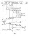
- a handover flow of the CS to the IMS (herein the WLAN access technology is employed) in the existing VCC technology is as illustrated in Fig. 1 .
- a voice handover to the WLAN may be initiated due to a degraded wireless environment of the CS network or an IMS priority.
- UE User Equipment
- the UE initiates the voice handover to the WLAN by sending an IMS call to an address identity associated with the VCC AS and sending an INVITE message to a Proxy Call Session Control Function (P-CSCF), which message then arrives at a Serving Call Session Control Function (S-CSCF).
- P-CSCF Proxy Call Session Control Function
- S-CSCF Serving Call Session Control Function
- the S-CSCF forwards the INVITE message to the VCC AS according to initial Filter Criteria, and the address identity associated with the VCC AS and a P-Asserted-Identity (privacy asserting identity) head (containing the CS domain Mobile Directory Number (MDN) of the UE) are combined to indicate the user equipment initiating the VCC handover.
- P-Asserted-Identity privacy asserting identity
- MDN Mobile Directory Number
- the VCC AS sends a re-INVITE message containing new Service Description Protocol (SDP) information of a WLAN call for the UE to the Other End Point (the other part of the call, including a network and a user equipment) through the S-CSCF.
- SDP Service Description Protocol
- the UE sends out ACK, which finally arrives at the Other End Point, thereby establishing a Session Initiation Protocol (SIP) call dialogue 3 between the UE and the VCC AS.
- SIP Session Initiation Protocol
- the VCC AS Upon reception of ACK, the VCC AS sends a BYE message to the MGCF through the S-CSCF to remove the CS voice call (an SIP call dialogue 2).
- 108 ⁇ 112 The CS voice call between a Mobile Switching Center (MSC) and the UE is released, and the MGCH returns 200 OK to the VCC AS.
- MSC Mobile Switching Center
- the existing VCC handover is assumed to be performed in an on-going state without consideration of non-on-going state factors of Ringing/Ring Back Tone (for a called/calling user scenario)/Keeping, etc.
- the UE may initiate a calling user flow, but a true user off-hook signal may not be transferred; and when a handover occurs with the UE of the calling user, the UE also may initiate a calling user flow, and at this time generation of a ring back tone (e.g., a color ring tone) may be disordered; and a handover may be too complex for the call keeping state.
- a ring back tone e.g., a color ring tone
- Embodiments of the invention provide a call handover control method, a communication system and a user equipment so as to prevent the user equipment from being switched when the user is in non-on-going states of Ringing/Ring Back Tone/Keeping, etc.
- a call handover control method based upon the network side includes: receiving a handover request from a user equipment, determining whether a call is on-going, and if so, then permitting a handover; otherwise performing an exception handling.
- a call handover control method based upon the user side includes: determining, by a user equipment, whether a call is on-going, and if so, then initiating a handover request; otherwise continuing with the call in the current network; and switching, by a multimedia sub-system network of the internet protocol upon reception of the handover request, the user equipment.
- a communication system includes: a user equipment adapted to send a handover request to a voice call continuity server; and the voice call continuity server adapted to receive the handover request, and to permit a handover upon determining that a call is on-going or to perform an exception handling upon determining that the call is in a non-on-going state.
- a user equipment includes: an information acquisition unit adapted to acquire and send handover information to a handover decision unit; the handover decision unit adapted to initiate a handover request upon determining that a call is on-going in accordance with the received handover information, and to continue with the call in the current network upon determining that the call is in a non-on-going state.
- the embodiments of the invention when the user requests a handover, it is firstly determined whether the call is in the on-going state, and if not so, then the handover is rejected, so that the embodiments of the invention can avoid effectively the user from being switched when the user is in non-on-going states of Ringing/Ring Back Tone/Keeping, etc.
- the method according to the embodiments of the invention is applicable to a GSM network, a UMTS network and a CDMA network, thereby improving adaptability of the invented method.
- the method according to the embodiments of the invention proposes a plurality of determination approaches for determining a Ring Back Tone in a CDMA network and calling state of Keeping, thereby improving flexibility of the invented method.
- Fig.1 illustrates a flow chart of a handover method in the prior art
- Fig.2 illustrates a general flow chart of a call handover control method according to an embodiment of the invention
- Fig.3 illustrates a flow chart for a calling UE in a GSM/UMTS network
- Fig.4 illustrates a flow chart for a calling UE in a CDMA network in the prior art
- Fig.5 illustrates a call flow chart in which an MSC issues off-hook information according to an embodiment of the invention
- Fig.6 illustrates a call flow chart in which a VCC AS issues hand-off information according to an embodiment of the invention.
- Fig.7(a) and Fig.7(b) are schematic diagram of a system according to an embodiment of the invention.
- the embodiments of the invention provide a call handover control method, a communication system and a user equipment so as to prevent the user equipment from being switched when the user is in non-on-going states of Ringing/Ring Back Tone/Keeping, etc.
- a flow of the call handover control method based on the network side is as follows:
- a user equipment initiates a handover request.
- the user equipment can detect a change of network condition and then initiates a handover request; or the user can request through the user equipment actively for a handover.
- the handover is performed.
- the exception handling may reject the handover, or store the handover request and feed back a wait message to the user equipment and then process the handover request after the call becomes in the on-going state.
- the handover request is rejected, to thereby prevent effectively the user from being switched when the user is in non-on-going states of Ringing/Ring Back Tone /Keeping, etc.
- an embodiment of the invention further provides a call handover control method based upon the user side in which the determination of a handover is made at the user side, i.e., a user equipment, that is, the user equipment detects the state of a call and initiates a handover request only if the call is on-going, and a multimedia sub-system network of the internet protocol performs the handover directly instead of performing the determination upon reception of the request initiated from the user equipment.
- the first embodiment relates to the control of a call handover of the IMS to the CS.
- a high rate IP access network is typically covered with hotspots, and after the UE leaves a hotspot, continuity of a call shall be maintained so that the call can be switched smoothly to the CS network.
- the UE when initiating or accepting the call at the IMS adopts the SIP protocol for signaling interaction to obtain the current state of the call, e.g., Ringing, Ring Back Tone, Keeping or the on-going state, through a signaling message, and thus the current state can be determined directly at the UE.
- the current state of the call e.g., Ringing, Ring Back Tone, Keeping or the on-going state
- a Second embodiment relates to the control of a call handover of the CS to the IMS in the Ringing state.
- the UE During ringing of a called user (the call has not been accepted by the local user), the UE knows the state of the call and therefore shall determine whether the local user has accepted the call when the UE makes a VCC handover decision so as to prevent the handover of the CS to the IMS from being performed during ringing.
- the handover of the CS to the IMS refers to that the UE after entering a hotspot switches a voice service to the IP access network of the IMS, while the UE may initiate a high rate data service, where the rate of Voice over IP (VoIP) is lower than that of the voice service over the CS network.
- VoIP Voice over IP
- a third embodiment relates to the control of a call handover of the CS to the IMS in the Ring Back Tone state when the UE initiates a call over the GSM/UMTS network.
- the calling user can determine from the message that the current state is the on-going state.
- the called UE sends a ring message to the MSC or Visitor Location Register (VLR) connected thereto.
- VLR Visitor Location Register
- the MSC/VLR to which the called UE is connected sends an Address Complete Message (ACM) to the MSC/VLR to which the calling UE is connected to inform that the called UE is ringing.
- ACM Address Complete Message
- the MSC/VLR to which the calling UE is connected prompts the calling UE of that the current call state is Ring Back Tone state.
- the called UE sends a Connect message to the MSC/VLR connected thereto.
- the MSC/VLR of the called party sends an Answer message (ANM message) to the MSC/VLR to which the calling UE is connected to inform that the called party has unhooked.
- NAM message Answer message
- the MSC/VLR to which the calling UE is connected prompts the calling UE of that the current call state is the on-going state.
- the UE determines whether off-hook information has been received (that is, whether the call is in the on-going state) when the UE makes a VCC handover decision, and if not so, then no handover is permitted.
- This embodiment is implemented through issuing off-hook information to the UE by the MSC.
- the called UE prompts completion of MSC/VLR assignment.
- the MSC/VLR of the called party sends an ACM message to the MSC/VLR to which the calling UE is connected to inform that the current state is that the called UE is ringing, that is, the calling UE accepts a ring back tone.
- the called UE When the called UE hooks off, the called UE sends a Connect message to the MSC/VLR as a prompt of that the called party has unhooked.
- the MSC/VLR of the called party sends an ANM message to the MSC/VLR to which the calling UE is connected to inform that the current state is the on-going state.
- the off-hook information is issued from the MSC in this embodiment: the MSC notifies the UE upon reception of the off-hook message (ANM/CON) of the called party, for example, by extending the existing message of Flash with information, to which a support for a new Information record is added.
- NAM/CON off-hook message
- the UE sends out an initial call message.
- the MSC invokes an initial call WIN trigger to obtain routing information.
- the CS side of the VCC AS acting as an SCP which receives MAP ORREQ (a request MAP message of the calling user).
- the VCC AS creates and stores the MDN and the CdPN (the telephone number of the called user) for a subsequent call and returns the IMS routing number of the VCC AS.
- the MSC/VLR sends to the MGCF of the UE visitor network an ISUP IAM message containing the routing information of the UE (i.e., the IMS routing number of the CdPN field and the UE MDN of the CgPN field) and a PCM/TDM trunk (for connection the MSC with the MGW).
- the routing information of the UE i.e., the IMS routing number of the CdPN field and the UE MDN of the CgPN field
- PCM/TDM trunk for connection the MSC with the MGW.
- the MGCF requests the MGW for connection with the PCM/TDM trunk and assigns an ephemeral termination for connection with the Other End Point (OEP).
- the MGCF sends INVITE to the I-CSCF in which the address identify (an E.164 number) associated with the VCC AS is in the Request URI head and the MDN of the UE is in the P-Asserted-ID head.
- the I-CSCF sends the INVITE to the VCC AS.
- the VCC AS sends to the I-GSCF the INVITE message containing the routing information of the UE.
- the Request URI head now contains the MDN of the UE, and P-Asserted-ID contains the CdPN stored in the step 502.
- the I-CSCF searches the HSS to obtain the address of an S-CSCF assigned to the UE during registration and sends INVITE to the S-CSCF.
- the S-CSCF sends to the VCC AS based upon the filter criteria an SIP INVITE message containing the routing information of the UE.
- the VCC AS acts as a Back to Back User Agent (B2BUA) and establishes a new call dialogue 2 and returns INVITE to the S-CSCF.
- B2BUA Back to Back User Agent
- the S-CSCF sends INVITE to the OEP once the filter criteria process is completed.
- the OEP responds with an SIP 180 Ringing message containing the SDP information of the OEP, the message finally reaches the MGCF.
- the MGCH modifies the MGW ephemeral termination in accordance with the OEP SDP and sends an ISUP ACM message to the MSC/VLR.
- the MSC/VLR sends a channel assignment message to the UE.
- the UE captures a 1x service channel.
- the OEP replies to the call and returns an SIP 200 OK message to the MGCF.
- the MGCG sends an ISUP ANM message to the MSC/VLR.
- the MSC issues to the UE a Flash With Information message carrying off-hook information of the Other End Point.
- the MGCF sends an SIP ACK message to the OEP to thereby accomplish the establishment of the call dialogue 1 between the MGCF and the VCC AS and the establishment of the call dialogue 2 between the VCC AS and the OEP.
- the MSC enables the UE to obtain the off-hook information by issuing to the UE the FWI message carrying the off-hook information of the Other End Point.
- AWI refers to the message of Alert With Information
- FWI refers to the message of Flash With Information
- f-dsch refers to the forward dedicated signaling channel (from the network to the UE); and f-csch refers to the forward common signaling channel (from the network to the UE).
- Flash With Information message is as illustrated in the following table: Field Length (bits) Numeral RECORD_TYPE 8 00010110 RECORD_LEN 8 00000000 Type-specific fields 8*RECORD_LEN Null
- the UE determines whether off-hook information has been received (that is, whether the call is in the on-going state) when the UE makes a VCC handover decision, and if not so, then no handover is permitted.
- This embodiment is implemented through issuing off-hook information to the UE by the VCC AS.
- the IMS network side sends off-hook information to the UE, for example, by sending a MESSAGE/NOTIFY message to the UE over an IP access network or by sending SMS to the UE.
- the VCC AS sends an SMDPP message to a Short Message Service Center (SMSC).
- SMSC Short Message Service Center
- the SMSC sends an SMSREQ message to a Home Location Register (HLR).
- HLR Home Location Register
- the SMSC sends to the MSC/VLR the SMDPP message containing a source address.
- the MSC/VLR sends an ADDS Deliver message to the BSC.
- the BSC sends an SMS message to the UE.
- the UE sends an ACK confirmation message to the BSC.
- the BSC sends an ADDS Deliver ACK confirmation message to the MSC/VLR.
- the MSC/VLR sends an SMDPP ACK confirmation message to the SMSC.
- the SMSC sends the SMDPP ACK confirmation message to the VCC AS.
- the text of SMS contains such information as the current state being the on-going state, the number of the calling/called user, etc.
- the UE can initiate the VCC handover normally without necessity to wait the off-hook information. If the IMS network detects that the current call is in the Ring Back Tone state, then the network side returns a rejection response message to the UE to reject the handover request.
- the VCC AS checks that the call is in the Ring Back Tone state and rejects the handover request: for the rejection, a Try-After head instructing the UE to retry after a period of time (e.g., 10 seconds) is contained.
- the VCC AS checks that the call is in the Ring Back Tone state and rejects the handover request; for the rejection no Try-After head is contained, and the UE decides by itself to retry after an interval of time (e.g., 15 seconds).
- the VCC AS checks that the call is in the Ring Back Tone state, rejects the handover request; for the rejection no Try-After head is contained, while a message of MESSAGE is sent, and the text of which message indicates that the Other End Point has not unhooked.
- the VCC-AS Upon reception of an event of off-hook by the user at the Other End Point, the VCC-AS sends to the UE a message of MESSAGE, the text of which indicates that the Other End Point has unhooked.
- the VCC AS checks that the call is in the Ring Back Tone state, rejects the handover request, for the rejection no Try-After head is contained, and defines a rejection reason as prohibition of a handover in the Ring Back Tone state.
- the UE Upon reception of the rejection reason, the UE sends a SUBSCRIBE message to the VCC AS to subscribe for an event of off-hook by the user at the Other End Point and waits for transmission of an off-hook event notification from the VCC AS.
- a rejection reason is defined as prohibition of a handover in the Ring Back Tone state, and the UE subscribes implicitly to the VCC AS for an event of off-hook by the user at the Other End Point (i.e., transmission of SUBSCRIBE message is not needed) and waits for an off-hook event notification from the VCC AS.
- a rejection reason is defined as prohibition of a handover in the Ring Back Tone state
- the UE waits for an off-hook event notification from the VCC AS.
- the VCC AS Upon reception of an event of off-hook by the user at the Other End Point, the VCC AS sends to the UE a message of MESSAGE, the text of which indicates the information of off-hook at the Other End Point.
- the above three embodiments are advantageous in that that the UE can accurately find the reason of the error. So it will not be necessary for the UE to repeatedly retry transmission of the handover request, therefore signaling consumption is reduced.
- the ACC AS may not reject directly the handover request initiated from the UE.
- the UE initiates normally the VCC handover.
- the IMS network detects that the current call is in the Ring Back Tone state, it returns to 182 (the request is waiting to be processed) or 183 (the request is being processed), and proceeds with the VCC handover flow after off-hook at the Other End Point.
- the local UE when a local Keeping operation is performed, the local UE can obtain the local call state, so that the UE shall determine whether the current call is in the call Keeping state when the UE performs a VCC handover decision to thereby prevent a handover of the CS to the IMS from being performed in the call Keeping state.
- the UE when a keeping operation is performed at the Other End Point, the UE knows that the current state of a call is Keeping for a GSM and UMTS networks. The reason exists in that the MSC to which the local UE is connected notifies the UE by issuing a Facility message after the keeping operation is performed at the Other End Point.
- the MSC When a keeping operation is performed at the Other End Point, the MSC will not notify by issuing any message for a CDMA network. Instead, detection is made by the IMS network; therefore, if the UE initiates a VCC handover request in this state, then the IMS network will reject the request, or modify the MSC of the CDMA network so as to issue call keeping information and call recovery information by the MSC.
- the processing in this case is in analogy to that of the handover control in the Ring Back Tone state when the UE initiates a call over the CDMA network, that is, in analogy to the fourth to twelfth embodiments, except that the call keeping information is transmitted to indicate that the call is held, and the call recovery information is transmitted to indicate that the call has been recovered.
- a system includes a user equipment 701 and a voice call continuity server 706.
- the user equipment 701 is adapted to send a handover request to the voice call continuity server 706, and the voice call continuity server 706 determines whether a call is on-going upon reception of the handover request, and if so, then the handover is permitted; otherwise an exception handling is performed.
- the system further includes a mobile switching center 703 adapted to send off-hook information to the user equipment 701.
- the system includes a user equipment 701, a base station controller 702, a mobile switching center 703, a home location register 704, a short message center 705 and a voice call continuity server 706.
- the user equipment 701 initiates a handover request to the voice call continuity server 706, the voice call continuity server 706 detects the state of a current call, the Other End Point after unhooking issues to the short message center 705 an SMS message containing off-hook information, which is transmitted to the user equipment 701 through the home location register 704, the mobile switching center 703 and the base station controller 702, and the user equipment 701 starts the handover upon reception of the off-hook message.
- the off-hook information and call keeping information can be transmitted from the mobile handover information 703 to the user equipment 701 or from the voice call continuity server 706 to the user equipment 701.
- a system includes a user equipment 701, a mobile switching center 703, a media gateway control unit 707, an inquiring call session control unit 708, a service call session control unit 709 and a voice call continuity server 706.
- the user equipment 701 includes an information acquisition unit and a handover decision unit.
- the information acquisition unit is adapted to acquire and send handover information to the handover decision unit; and the handover decision unit determines from received handover information whether a call is on-going, and if so, then a handover request is initiated; otherwise the call continues in the current network.
- the program may be stored in a computer readable storage medium, e.g., an ROM/RAM, a magnetic disk, an optical disk, etc., and when the program is being executed the steps of the above method are involved.
- a computer readable storage medium e.g., an ROM/RAM, a magnetic disk, an optical disk, etc.
Abstract
Description
- This application claims priority to Chinese Patent Application No.
200610127153.8 - The present invention relates to the field of mobile communications and in particular to a call handover control method, a communication system and a user equipment.
- Voice Call Continuity (VCC) can enable communication of a user moving between various access technologies to keep continuous. For example, when the user moves from a traditional 2G network (e.g., Global System for Mobile communications (GSM), Code Division Multiple Access (CDMA), etc.) to a 3G network (e.g., a Universal Mobile Telecommunications System (UMTS), etc.), a High Rate Packet Data (HRPD) system, etc.), his communication proceeds while initiating another 3G service, e.g., an high rate access to the Internet.
- The VCC technology is based upon the Internet protocol Multimedia Subsystem (IMS), which is a network over an IP access network (the PS domain part of the UMTS, the HRPD network or a Wireless Local Area Network (WLAN)) and which offers basic service functions on the basic of which an operator can develop various services. In order to enable the VCC, when a user initiates/receives a call over a Circuit Switched (CS) network (i.e., the 2G network), call signaling will be directed into the IMS network in which a network element of VCC Application Server (VCC AS) can control VCC handover. A network element through which the IMS is directed into the CS network is a Media Gateway Control Function (MGCF), which also controls an MGW to perform routing of a bearer.
- A handover flow of the CS to the IMS (herein the WLAN access technology is employed) in the existing VCC technology is as illustrated in
Fig. 1 . - When a UE enjoying a CS voice service enters the coverage of the WLAN, a voice handover to the WLAN may be initiated due to a degraded wireless environment of the CS network or an IMS priority.
- A specific flow is as follows.
- 101. If the User Equipment (UE) has not been registered with the IMS, then a registration is performed.
- 102. The UE initiates the voice handover to the WLAN by sending an IMS call to an address identity associated with the VCC AS and sending an INVITE message to a Proxy Call Session Control Function (P-CSCF), which message then arrives at a Serving Call Session Control Function (S-CSCF).
- 103. The S-CSCF forwards the INVITE message to the VCC AS according to initial Filter Criteria, and the address identity associated with the VCC AS and a P-Asserted-Identity (privacy asserting identity) head (containing the CS domain Mobile Directory Number (MDN) of the UE) are combined to indicate the user equipment initiating the VCC handover.
- 104. The VCC AS sends a re-INVITE message containing new Service Description Protocol (SDP) information of a WLAN call for the UE to the Other End Point (the other part of the call, including a network and a user equipment) through the S-CSCF.
- 105. The other end point responds with 200 OK, which finally arrives at the UE.
- 106. The UE sends out ACK, which finally arrives at the Other End Point, thereby establishing a Session Initiation Protocol (SIP) call dialogue 3 between the UE and the VCC AS.
- 107. Upon reception of ACK, the VCC AS sends a BYE message to the MGCF through the S-CSCF to remove the CS voice call (an SIP call dialogue 2).
- 108∼112: The CS voice call between a Mobile Switching Center (MSC) and the UE is released, and the MGCH returns 200 OK to the VCC AS.
- However, the existing VCC handover is assumed to be performed in an on-going state without consideration of non-on-going state factors of Ringing/Ring Back Tone (for a called/calling user scenario)/Keeping, etc. For example, when a handover occurs while the UE of the called user rings, the UE may initiate a calling user flow, but a true user off-hook signal may not be transferred; and when a handover occurs with the UE of the calling user, the UE also may initiate a calling user flow, and at this time generation of a ring back tone (e.g., a color ring tone) may be disordered; and a handover may be too complex for the call keeping state.
- Embodiments of the invention provide a call handover control method, a communication system and a user equipment so as to prevent the user equipment from being switched when the user is in non-on-going states of Ringing/Ring Back Tone/Keeping, etc.
- A call handover control method based upon the network side according to an embodiment of the invention includes: receiving a handover request from a user equipment, determining whether a call is on-going, and if so, then permitting a handover; otherwise performing an exception handling.
- A call handover control method based upon the user side according to an embodiment of the invention includes: determining, by a user equipment, whether a call is on-going, and if so, then initiating a handover request; otherwise continuing with the call in the current network; and switching, by a multimedia sub-system network of the internet protocol upon reception of the handover request, the user equipment.
- A communication system according to an embodiment of the invention includes: a user equipment adapted to send a handover request to a voice call continuity server; and the voice call continuity server adapted to receive the handover request, and to permit a handover upon determining that a call is on-going or to perform an exception handling upon determining that the call is in a non-on-going state.
- A user equipment according to an embodiment of the invention includes: an information acquisition unit adapted to acquire and send handover information to a handover decision unit; the handover decision unit adapted to initiate a handover request upon determining that a call is on-going in accordance with the received handover information, and to continue with the call in the current network upon determining that the call is in a non-on-going state.
- As can be apparent from the above technical solutions, the embodiments of the invention have the following advantages:
- Firstly in the embodiments of the invention, when the user requests a handover, it is firstly determined whether the call is in the on-going state, and if not so, then the handover is rejected, so that the embodiments of the invention can avoid effectively the user from being switched when the user is in non-on-going states of Ringing/Ring Back Tone/Keeping, etc.
- Secondly, the method according to the embodiments of the invention is applicable to a GSM network, a UMTS network and a CDMA network, thereby improving adaptability of the invented method.
- Finally, the method according to the embodiments of the invention proposes a plurality of determination approaches for determining a Ring Back Tone in a CDMA network and calling state of Keeping, thereby improving flexibility of the invented method.
-
Fig.1 illustrates a flow chart of a handover method in the prior art; -
Fig.2 illustrates a general flow chart of a call handover control method according to an embodiment of the invention; -
Fig.3 illustrates a flow chart for a calling UE in a GSM/UMTS network; -
Fig.4 illustrates a flow chart for a calling UE in a CDMA network in the prior art; -
Fig.5 illustrates a call flow chart in which an MSC issues off-hook information according to an embodiment of the invention; -
Fig.6 illustrates a call flow chart in which a VCC AS issues hand-off information according to an embodiment of the invention; and -
Fig.7(a) and Fig.7(b) are schematic diagram of a system according to an embodiment of the invention. - The embodiments of the invention provide a call handover control method, a communication system and a user equipment so as to prevent the user equipment from being switched when the user is in non-on-going states of Ringing/Ring Back Tone/Keeping, etc.
- Referring to
Fig.2 , a flow of the call handover control method based on the network side according to an embodiment of the invention is as follows: - 201. A user equipment initiates a handover request.
- Particularly, when the user movies into a different network coverage area, the user equipment can detect a change of network condition and then initiates a handover request; or the user can request through the user equipment actively for a handover.
- 202. It is determined whether a call is on-going, and if so, then the flow goes to the
step 203; otherwise the flow goes to thestep 204. - 203. The handover is performed.
- 204. An exception handling is performed.
- Particularly, the exception handling may reject the handover, or store the handover request and feed back a wait message to the user equipment and then process the handover request after the call becomes in the on-going state.
- As can be apparent from the above solution, in the embodiment of the invention, it is firstly determined whether the current call is in the on-going state prior to performing the handover, and if not so, then the handover request is rejected, to thereby prevent effectively the user from being switched when the user is in non-on-going states of Ringing/Ring Back Tone /Keeping, etc.
- Furthermore, an embodiment of the invention further provides a call handover control method based upon the user side in which the determination of a handover is made at the user side, i.e., a user equipment, that is, the user equipment detects the state of a call and initiates a handover request only if the call is on-going, and a multimedia sub-system network of the internet protocol performs the handover directly instead of performing the determination upon reception of the request initiated from the user equipment.
- The invention will be described in details below with reference to the embodiments thereof.
- The first embodiment relates to the control of a call handover of the IMS to the CS.
- A high rate IP access network is typically covered with hotspots, and after the UE leaves a hotspot, continuity of a call shall be maintained so that the call can be switched smoothly to the CS network.
- In this case, the UE when initiating or accepting the call at the IMS adopts the SIP protocol for signaling interaction to obtain the current state of the call, e.g., Ringing, Ring Back Tone, Keeping or the on-going state, through a signaling message, and thus the current state can be determined directly at the UE.
- A Second embodiment relates to the control of a call handover of the CS to the IMS in the Ringing state.
- During ringing of a called user (the call has not been accepted by the local user), the UE knows the state of the call and therefore shall determine whether the local user has accepted the call when the UE makes a VCC handover decision so as to prevent the handover of the CS to the IMS from being performed during ringing.
- Particularly, the handover of the CS to the IMS refers to that the UE after entering a hotspot switches a voice service to the IP access network of the IMS, while the UE may initiate a high rate data service, where the rate of Voice over IP (VoIP) is lower than that of the voice service over the CS network.
- A third embodiment relates to the control of a call handover of the CS to the IMS in the Ring Back Tone state when the UE initiates a call over the GSM/UMTS network.
- As illustrated in
Fig.3 , for a call initiated from the UE over the GSM/UMTS network, since the MSC to which the calling UE is connected issues to the calling user a Connect message indicating off-hook of the called user at the Other End Point when the called user hooks off, the calling user can determine from the message that the current state is the on-going state. - An essential flow is as follows.
- 301. The called UE sends a ring message to the MSC or Visitor Location Register (VLR) connected thereto.
- 302. The MSC/VLR to which the called UE is connected sends an Address Complete Message (ACM) to the MSC/VLR to which the calling UE is connected to inform that the called UE is ringing.
- 303. The MSC/VLR to which the calling UE is connected prompts the calling UE of that the current call state is Ring Back Tone state.
- 304. When the called user hooks off, the called UE sends a Connect message to the MSC/VLR connected thereto.
- 305. The MSC/VLR of the called party sends an Answer message (ANM message) to the MSC/VLR to which the calling UE is connected to inform that the called party has unhooked.
- 306. The MSC/VLR to which the calling UE is connected prompts the calling UE of that the current call state is the on-going state.
- In case of a handover of the CS to the IMS, when the UE initiates a call over the CDMA network, there are nine particular approaches of controlling a call handover in the Ring Back Tone state for which a reference can be made to the following, the fourth to the twelve embodiments.
- In the fourth embodiment, the UE determines whether off-hook information has been received (that is, whether the call is in the on-going state) when the UE makes a VCC handover decision, and if not so, then no handover is permitted. This embodiment is implemented through issuing off-hook information to the UE by the MSC.
- Referring to
Fig.4 , in the CDMA network of the prior art, the MSC to which the calling UE is connected will not issue any off-hook information after the Other End Point hooks off, and therefore the UE can not distinguish between the Ring Back Tone and on-going states. A flow of the prior art is as follows: - 401. The called UE prompts completion of MSC/VLR assignment.
- 402. The MSC/VLR of the called party sends an ACM message to the MSC/VLR to which the calling UE is connected to inform that the current state is that the called UE is ringing, that is, the calling UE accepts a ring back tone.
- 403. When the called UE hooks off, the called UE sends a Connect message to the MSC/VLR as a prompt of that the called party has unhooked.
- 404. The MSC/VLR of the called party sends an ANM message to the MSC/VLR to which the calling UE is connected to inform that the current state is the on-going state.
- In order that the calling UE can receive the off-hook information, the existing flow shall be modified, the off-hook information is issued from the MSC in this embodiment: the MSC notifies the UE upon reception of the off-hook message (ANM/CON) of the called party, for example, by extending the existing message of Flash with information, to which a support for a new Information record is added.
- Referring to
Fig.5 , a specific flow is as follows. - 501. The UE sends out an initial call message.
- 502. The MSC invokes an initial call WIN trigger to obtain routing information. The CS side of the VCC AS acting as an SCP which receives MAP ORREQ (a request MAP message of the calling user).
- 503. The VCC AS creates and stores the MDN and the CdPN (the telephone number of the called user) for a subsequent call and returns the IMS routing number of the VCC AS.
- 504. The MSC/VLR sends to the MGCF of the UE visitor network an ISUP IAM message containing the routing information of the UE (i.e., the IMS routing number of the CdPN field and the UE MDN of the CgPN field) and a PCM/TDM trunk (for connection the MSC with the MGW).
- 505. The MGCF requests the MGW for connection with the PCM/TDM trunk and assigns an ephemeral termination for connection with the Other End Point (OEP).The MGCF sends INVITE to the I-CSCF in which the address identify (an E.164 number) associated with the VCC AS is in the Request URI head and the MDN of the UE is in the P-Asserted-ID head. The I-CSCF sends the INVITE to the VCC AS.
- 506. The VCC AS sends to the I-GSCF the INVITE message containing the routing information of the UE. The Request URI head now contains the MDN of the UE, and P-Asserted-ID contains the CdPN stored in the
step 502. - 507. The I-CSCF searches the HSS to obtain the address of an S-CSCF assigned to the UE during registration and sends INVITE to the S-CSCF. The S-CSCF sends to the VCC AS based upon the filter criteria an SIP INVITE message containing the routing information of the UE.
- 508. The VCC AS acts as a Back to Back User Agent (B2BUA) and establishes a new call dialogue 2 and returns INVITE to the S-CSCF.
- 509. The S-CSCF sends INVITE to the OEP once the filter criteria process is completed.
- 510. The OEP responds with an SIP 180 Ringing message containing the SDP information of the OEP, the message finally reaches the MGCF.
- 511. The MGCH modifies the MGW ephemeral termination in accordance with the OEP SDP and sends an ISUP ACM message to the MSC/VLR.
- 512. The MSC/VLR sends a channel assignment message to the UE.
- 513. The UE captures a 1x service channel.
- 514. The OEP replies to the call and returns an SIP 200 OK message to the MGCF.
- 515. The MGCG sends an ISUP ANM message to the MSC/VLR.
- 516. The MSC issues to the UE a Flash With Information message carrying off-hook information of the Other End Point.
- 517. The MGCF sends an SIP ACK message to the OEP to thereby accomplish the establishment of the call dialogue 1 between the MGCF and the VCC AS and the establishment of the call dialogue 2 between the VCC AS and the OEP.
- As can be apparent from the above flow, the MSC enables the UE to obtain the off-hook information by issuing to the UE the FWI message carrying the off-hook information of the Other End Point.
- A new type of information record as illustrated in the following table shall be defined in the above flow:
Table 1 Information record Record type (binary) Message type f-csch f-dsch Call wait information 00010101 AWI N Y FWI N Y Off-hook information 00010110 FWI N Y - Particularly, AWI refers to the message of Alert With Information, FWI refers to the message of Flash With Information, f-dsch refers to the forward dedicated signaling channel (from the network to the UE); and f-csch refers to the forward common signaling channel (from the network to the UE).
- The format of the Flash With Information message is as illustrated in the following table:
Field Length (bits) Numeral RECORD_TYPE 8 00010110 RECORD_LEN 8 00000000 Type-specific fields 8*RECORD_LEN Null - In the fifth embodiment, the UE determines whether off-hook information has been received (that is, whether the call is in the on-going state) when the UE makes a VCC handover decision, and if not so, then no handover is permitted. This embodiment is implemented through issuing off-hook information to the UE by the VCC AS.
- The IMS network side sends off-hook information to the UE, for example, by sending a MESSAGE/NOTIFY message to the UE over an IP access network or by sending SMS to the UE.
- Referring to
Fig.6 , a specific flow is as follows. - 601. The VCC AS sends an SMDPP message to a Short Message Service Center (SMSC).
- 602. The SMSC sends an SMSREQ message to a Home Location Register (HLR).
- 603. The SMSC sends to the MSC/VLR the SMDPP message containing a source address.
- 604. The MSC/VLR sends an ADDS Deliver message to the BSC.
- 605. The BSC sends an SMS message to the UE.
- 606. The UE sends an ACK confirmation message to the BSC.
- 607. The BSC sends an ADDS Deliver ACK confirmation message to the MSC/VLR.
- 608. The MSC/VLR sends an SMDPP ACK confirmation message to the SMSC.
- 609. The SMSC sends the SMDPP ACK confirmation message to the VCC AS.
- Particularly, the text of SMS contains such information as the current state being the on-going state, the number of the calling/called user, etc.
- Furthermore, the UE can initiate the VCC handover normally without necessity to wait the off-hook information. If the IMS network detects that the current call is in the Ring Back Tone state, then the network side returns a rejection response message to the UE to reject the handover request.
- In the sixth embodiment, the VCC AS checks that the call is in the Ring Back Tone state and rejects the handover request: for the rejection, a Try-After head instructing the UE to retry after a period of time (e.g., 10 seconds) is contained.
- In the seventh embodiment, the VCC AS checks that the call is in the Ring Back Tone state and rejects the handover request; for the rejection no Try-After head is contained, and the UE decides by itself to retry after an interval of time (e.g., 15 seconds).
- In the eighth embodiment, the VCC AS checks that the call is in the Ring Back Tone state, rejects the handover request; for the rejection no Try-After head is contained, while a message of MESSAGE is sent, and the text of which message indicates that the Other End Point has not unhooked. Upon reception of an event of off-hook by the user at the Other End Point, the VCC-AS sends to the UE a message of MESSAGE, the text of which indicates that the Other End Point has unhooked.
- The above three embodiments are advantageous in that that they are simple and convenient to implement.
- In the ninth embodiment, the VCC AS checks that the call is in the Ring Back Tone state, rejects the handover request, for the rejection no Try-After head is contained, and defines a rejection reason as prohibition of a handover in the Ring Back Tone state. Upon reception of the rejection reason, the UE sends a SUBSCRIBE message to the VCC AS to subscribe for an event of off-hook by the user at the Other End Point and waits for transmission of an off-hook event notification from the VCC AS.
- In the tenth embodiment, a rejection reason is defined as prohibition of a handover in the Ring Back Tone state, and the UE subscribes implicitly to the VCC AS for an event of off-hook by the user at the Other End Point (i.e., transmission of SUBSCRIBE message is not needed) and waits for an off-hook event notification from the VCC AS.
- In the eleventh embodiment, a rejection reason is defined as prohibition of a handover in the Ring Back Tone state, the UE waits for an off-hook event notification from the VCC AS. Upon reception of an event of off-hook by the user at the Other End Point, the VCC AS sends to the UE a message of MESSAGE, the text of which indicates the information of off-hook at the Other End Point.
- The above three embodiments are advantageous in that that the UE can accurately find the reason of the error. So it will not be necessary for the UE to repeatedly retry transmission of the handover request, therefore signaling consumption is reduced.
- Alternatively, the ACC AS may not reject directly the handover request initiated from the UE.
- In the twelfth embodiment, the UE initiates normally the VCC handover. As the IMS network detects that the current call is in the Ring Back Tone state, it returns to 182 (the request is waiting to be processed) or 183 (the request is being processed), and proceeds with the VCC handover flow after off-hook at the Other End Point.
- In the case of a handover of the CS to the IMS, there is control on a handover of a call initiated by the UE over the CDMA network in the call Keeping state.
- In the thirteenth embodiment, when a local Keeping operation is performed, the local UE can obtain the local call state, so that the UE shall determine whether the current call is in the call Keeping state when the UE performs a VCC handover decision to thereby prevent a handover of the CS to the IMS from being performed in the call Keeping state.
- In the fourth embodiment, when a keeping operation is performed at the Other End Point, the UE knows that the current state of a call is Keeping for a GSM and UMTS networks. The reason exists in that the MSC to which the local UE is connected notifies the UE by issuing a Facility message after the keeping operation is performed at the Other End Point.
- When a keeping operation is performed at the Other End Point, the MSC will not notify by issuing any message for a CDMA network. Instead, detection is made by the IMS network; therefore, if the UE initiates a VCC handover request in this state, then the IMS network will reject the request, or modify the MSC of the CDMA network so as to issue call keeping information and call recovery information by the MSC.
- The processing in this case is in analogy to that of the handover control in the Ring Back Tone state when the UE initiates a call over the CDMA network, that is, in analogy to the fourth to twelfth embodiments, except that the call keeping information is transmitted to indicate that the call is held, and the call recovery information is transmitted to indicate that the call has been recovered.
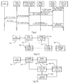
- Referring to
Fig.7(a) to Fig.7(b) , a system according to an embodiment of the invention includes auser equipment 701 and a voicecall continuity server 706. Theuser equipment 701 is adapted to send a handover request to the voicecall continuity server 706, and the voicecall continuity server 706 determines whether a call is on-going upon reception of the handover request, and if so, then the handover is permitted; otherwise an exception handling is performed. - Particularly, the system further includes a
mobile switching center 703 adapted to send off-hook information to theuser equipment 701. - The invented system will be described below taking as an example a device which the VCC AS issues off-hook information in an SMS message to the UE. Referring to
Fig.7(a) , the system according to an embodiment of the invention includes auser equipment 701, abase station controller 702, amobile switching center 703, ahome location register 704, ashort message center 705 and a voicecall continuity server 706. Theuser equipment 701 initiates a handover request to the voicecall continuity server 706, the voicecall continuity server 706 detects the state of a current call, the Other End Point after unhooking issues to theshort message center 705 an SMS message containing off-hook information, which is transmitted to theuser equipment 701 through thehome location register 704, themobile switching center 703 and thebase station controller 702, and theuser equipment 701 starts the handover upon reception of the off-hook message. - The off-hook information and call keeping information can be transmitted from the
mobile handover information 703 to theuser equipment 701 or from the voicecall continuity server 706 to theuser equipment 701. - As illustrated in
Fig.7(b) , a system according to an embodiment of the invention includes auser equipment 701, amobile switching center 703, a mediagateway control unit 707, an inquiring callsession control unit 708, a service callsession control unit 709 and a voicecall continuity server 706. - The
user equipment 701 according to the embodiment of the invention includes an information acquisition unit and a handover decision unit. The information acquisition unit is adapted to acquire and send handover information to the handover decision unit; and the handover decision unit determines from received handover information whether a call is on-going, and if so, then a handover request is initiated; otherwise the call continues in the current network. - It shall be noted that those ordinarily skilled in the art can appreciate that all or part of the steps in the above methods according to the embodiments can be implemented by a program instructing relevant hardware. The program may be stored in a computer readable storage medium, e.g., an ROM/RAM, a magnetic disk, an optical disk, etc., and when the program is being executed the steps of the above method are involved.
- The foregoing descriptions are illustrative in details of the call handover control method, the communication system and the user equipment according to the invention, the principle and embodiments of the invention have been set forth with the specific examples, and the above descriptions of the embodiments are merely intended to facilitate understanding of the invented method and the core idea thereof. Also variations of the embodiments and their application scopes will be possibly made by those ordinarily skilled in the art in light of the invented idea. Accordingly, the disclosure in the specification shall be considered as limiting the invention.
Claims (22)
- A call handover control method based upon the network side, comprising:receiving a handover request from a user equipment, determining whether a call is on-going, and if so, then permitting a handover; otherwise performing an exception handling.
- The call handover control method according to claim 1, wherein the step of determining whether the call is in the on-going state comprises:detecting, by a voice call continuity server, the state of the current call, and determining whether the call is in the on-going state in accordance with a detection result;the detection result comprises a Ring Back Tone state, a call Keeping state or the on-going state.
- The call handover control method according to claim 2, wherein if the call is not in the on-going state but in the Ring Back Tone state or the call Keeping state, then the exception handling comprises: sending, by the voice call continuity server, response information rejecting the handover request.
- The call handover control method according to claim 3, wherein after the voice call continuity server rejects the handover request, the exception handling further comprises: instructing the user equipment to request a handover again after a preset period of time.
- The call handover control method according to claim 3, wherein if the current call is not in the on-going state but in the Ring Back Tone state, then after the voice call continuity server sends the response information rejecting the handover request, the method further comprises:sending, by the voice call continuity server, off-hook information to the user equipment; andreceiving the handover request from the user equipment, and performing the handover according to the handover request.
- The call handover control method according to claim 5, wherein the response information rejecting the handover request contains a rejection reason, which is the Ring Back Tone state.
- The call handover control method according to claim 5 or 6, wherein before the voice call continuity server sends the off-hook information to the user equipment, the method further comprises:sending, by the user equipment, an off-hook event subscription message to the voice call continuity server.
- The call handover control method according to claim 3, wherein if the current call is not in the on-going state but in the call Keeping state, then after the voice call continuity server sends the response information rejecting the handover request, the method further comprises:sending, by the voice call continuity server, call recovery information to the user equipment; andreceiving the handover request from the user equipment, and performing the handover according to the handover request.
- The call handover control method according to claim 8, wherein the response information rejecting the handover request contains a rejection reason, which is the Ring Back Tone state.
- The call handover control method according to claim 8 or 9, wherein before the voice call continuity server sends the call recovery information to the user equipment, the method further comprises:sending, by the user equipment, a call recovery event subscription message to the voice call continuity server.
- The call handover control method according to claim 2, wherein if the current call is not in the on-going state but in the Ring Back Tone state, then the exception handling is:returning, by the voice call continuity server, to the user equipment, information that the request is being processed or the request is waiting to be processed, and storing the handover request initiated from the user equipment; andperforming, by the voice call continuity server, the handover according to the stored handover request upon reception of off-hook information.
- The call handover control method according to claim 2, wherein if the current call is not in the on-going state but in the call Keeping state, then the exception handling is:returning, by the voice call continuity server, to the user equipment, information that the request is being processed or the request is waiting to be processed, and storing the handover request initiated by the user equipment; andperforming, by the voice call continuity server, the handover according to the stored handover request upon reception of call recovery information.
- A call handover control method based upon the user side, comprising:determining, by a user equipment, whether a call is on-going, and if so, then initiating a handover request; otherwise continuing with the call in the current network; andswitching, by a multimedia sub-system network of the internet protocol, the user equipment, upon reception of the handover request.
- The call handover control method according to claim 13, wherein the step of determining by the user equipment whether the call is in the on-going state comprises:obtaining the state of the current call by a message of the session initiation protocol, and determining whether the call is in the on-going state in accordance with the call state;the call state comprises a Ringing state, a Ring Back Tone state, a call Keeping state or the on-going state.
- The call handover control method according to claim 13, wherein the step of determining by the user equipment whether the call is in the on-going state comprises:determining that the call is in the on-going state if the user equipment receives or sends off-hook information.
- The call handover control method according to claim 15, wherein after the user equipment receives or sends the off-hook information, the method further comprises:determining that the call is not in the on-going state if the user equipment sends or receives call keeping information.
- The call handover control method according to claim 15, wherein the off-hook information received by the user equipment is from a mobile switching center or a multimedia sub-system network of the internet protocol.
- The call handover control method according to claim 16, wherein the call keeping information received by the user equipment is from a mobile switching center or a multimedia sub-system network of the internet protocol.
- A communication system, comprising:a user equipment adapted to send a handover request to a voice call continuity server; andthe voice call continuity server adapted to receive the handover request, and to permit a handover upon determining that a call is on-going or to perform an exception handling upon determining that the call is in a non-on-going state.
- The communication system according to claim 19, further comprising a mobile switching center to send off-hook information or call keeping information to the user equipment.
- The communication system according to claim 19, wherein the voice call continuity server is adapted to send off-hook information or call keeping information to the user equipment.
- A user equipment, characterized by comprising:an information acquisition unit adapted to acquire and send handover information to a handover decision unit; andthe handover decision unit adapted to initiate a handover request upon determining that a call is on-going in accordance with the received handover information, and to continue with the call in the current network upon determining that the call is in a non-on-going state.
Priority Applications (1)
| Application Number | Priority Date | Filing Date | Title |
|---|---|---|---|
| EP10161297A EP2207380B1 (en) | 2006-09-05 | 2007-07-18 | A call handoff control method, voice call continuity server and system for prodiving voice call continuity |
Applications Claiming Priority (2)
| Application Number | Priority Date | Filing Date | Title |
|---|---|---|---|
| CNA2006101271538A CN101087478A (en) | 2006-09-05 | 2006-09-05 | Control method for call switching, communication system and user device |
| PCT/CN2007/070314 WO2008028416A1 (en) | 2006-09-05 | 2007-07-18 | A call handoff control method and communication system thereof and a user device |
Related Child Applications (1)
| Application Number | Title | Priority Date | Filing Date |
|---|---|---|---|
| EP10161297.6 Division-Into | 2010-04-28 |
Publications (3)
| Publication Number | Publication Date |
|---|---|
| EP2071855A1 true EP2071855A1 (en) | 2009-06-17 |
| EP2071855A4 EP2071855A4 (en) | 2010-01-27 |
| EP2071855B1 EP2071855B1 (en) | 2011-03-30 |
Family
ID=38938174
Family Applications (2)
| Application Number | Title | Priority Date | Filing Date |
|---|---|---|---|
| EP10161297A Active EP2207380B1 (en) | 2006-09-05 | 2007-07-18 | A call handoff control method, voice call continuity server and system for prodiving voice call continuity |
| EP07764241A Active EP2071855B1 (en) | 2006-09-05 | 2007-07-18 | A call handoff control method, user device, voice call continuity server and communication system for prodiving voice call continuity |
Family Applications Before (1)
| Application Number | Title | Priority Date | Filing Date |
|---|---|---|---|
| EP10161297A Active EP2207380B1 (en) | 2006-09-05 | 2007-07-18 | A call handoff control method, voice call continuity server and system for prodiving voice call continuity |
Country Status (6)
| Country | Link |
|---|---|
| US (2) | US8089934B2 (en) |
| EP (2) | EP2207380B1 (en) |
| CN (3) | CN101087478A (en) |
| AT (2) | ATE507697T1 (en) |
| DE (2) | DE602007014270D1 (en) |
| WO (1) | WO2008028416A1 (en) |
Families Citing this family (30)
| Publication number | Priority date | Publication date | Assignee | Title |
|---|---|---|---|---|
| CN101232681B (en) * | 2008-02-01 | 2011-06-22 | 中兴通讯股份有限公司 | Method and device for implementing voice call continuity on mobile phone |
| CN101583136B (en) * | 2008-05-12 | 2011-07-20 | 华为技术有限公司 | Method and terminal for measurement processing |
| US8483680B2 (en) * | 2008-10-03 | 2013-07-09 | Qualcomm Incorporated | Handling failure scenarios for voice call continuity |
| US8264990B2 (en) * | 2010-02-01 | 2012-09-11 | Microsoft Corporation | Using consultation call to transfer call across endpoints |
| JP5774022B2 (en) * | 2010-11-18 | 2015-09-02 | パナソニック インテレクチュアル プロパティ コーポレーション オブアメリカPanasonic Intellectual Property Corporation of America | Communication terminal and network node |
| US8842662B2 (en) * | 2011-01-07 | 2014-09-23 | Samsung Electronics Co., Ltd. | Techniques for trunk optimization for IMS voice calls between originating UE and terminating UE homed in a circuit switched network |
| CN102316232A (en) * | 2011-05-23 | 2012-01-11 | 中兴通讯股份有限公司 | Call-timing processing method, device and system |
| US20130107860A1 (en) * | 2011-10-27 | 2013-05-02 | Qualcomm Incorporated | REDUCING SERVICE INTERRUPTION OF VOICE OVER INTERNET PROTOCOL (VoIP) CALLS DUE TO INTER-RADIO ACCESS TECHNOLOGY (RAT) HANDOVER |
| GB2500586B (en) | 2012-03-23 | 2014-05-07 | Samsung Electronics Co Ltd | Provision of a customised alerting notification |
| CN103581894B (en) * | 2012-08-09 | 2017-05-24 | 中兴通讯股份有限公司 | SRVCC same-number-supporting system and method |
| US10004004B2 (en) | 2014-07-15 | 2018-06-19 | T-Mobile Usa, Inc. | Telecommunication equipment measuring pre-establishment service interruptions |
| US10039019B2 (en) | 2014-07-24 | 2018-07-31 | T-Mobile Usa, Inc. | Telecommunications network non-establishment response |
| US10594741B2 (en) | 2014-08-04 | 2020-03-17 | T-Mobile Usa, Inc. | Suppressing third party registration and third party deregistration actions |
| KR102337715B1 (en) | 2015-04-23 | 2021-12-10 | 삼성전자주식회사 | Electronic device and call processing method thereof |
| CN106714256B (en) * | 2015-11-12 | 2020-01-07 | 中国移动通信集团公司 | Method and device for triggering network switching |
| CN107222896B (en) * | 2016-03-22 | 2020-08-07 | 中国移动通信集团公司 | Voice service switching method and base station |
| CN107333302B (en) * | 2016-04-28 | 2021-08-03 | 中兴通讯股份有限公司 | Service processing method and device |
| CN107483755A (en) * | 2016-06-07 | 2017-12-15 | 中兴通讯股份有限公司 | A kind of method of audio call and base station |
| CN107580343B (en) * | 2016-07-04 | 2021-07-27 | 中兴通讯股份有限公司 | Management method and device for single-channel voice call continuity switching |
| CN108064061B (en) * | 2016-11-07 | 2020-09-08 | 中兴通讯股份有限公司 | Message sending method, device and system |
| CN108243461B (en) * | 2016-12-26 | 2021-01-29 | 辰芯科技有限公司 | Method for switching terminal call |
| US10945170B2 (en) | 2016-12-29 | 2021-03-09 | Huawei Technologies Co., Ltd. | Communication method and mobile terminal |
| CN109246058B (en) * | 2017-07-10 | 2021-01-15 | 中国移动通信有限公司研究院 | False caller identification method and device, electronic equipment and storage medium |
| CN109819481B (en) * | 2017-11-20 | 2021-05-11 | 华为技术有限公司 | Network switching method and session management network element |
| US11812515B2 (en) | 2018-05-01 | 2023-11-07 | Intermetro Communications, Inc. | Multiple active network wireless device using a shadow number |
| MX2020011466A (en) | 2018-05-01 | 2021-03-31 | Intermetro Communications Inc | Multiple active network wireless device. |
| CN109814949B (en) * | 2019-01-07 | 2022-04-22 | 平安科技(深圳)有限公司 | Virtual telephone state switching method and device, computer equipment and storage medium |
| US10687182B1 (en) * | 2019-05-31 | 2020-06-16 | Apple Inc. | Accessory device texting enhancements |
| CN110995939B (en) * | 2019-12-20 | 2021-09-28 | 惠州Tcl移动通信有限公司 | Switching method and device of call network and storage medium |
| CN112637158B (en) * | 2020-12-14 | 2023-11-14 | 努比亚技术有限公司 | Call network regulation and control method, device and computer readable storage medium |
Citations (2)
| Publication number | Priority date | Publication date | Assignee | Title |
|---|---|---|---|---|
| US20040264410A1 (en) * | 2003-06-30 | 2004-12-30 | Motorola, Inc. | Method and apparatus for providing a communication unit with a handoff between networks |
| WO2005025108A2 (en) * | 2003-08-29 | 2005-03-17 | Motorola, Inc. , A Corporation Of The State Of Delaware | Method and apparatus in a wireless communication system for facilitating a handoff |
Family Cites Families (13)
| Publication number | Priority date | Publication date | Assignee | Title |
|---|---|---|---|---|
| KR910003923B1 (en) * | 1988-06-30 | 1991-06-15 | 삼성전자 주식회사 | Method transmitting automatic arrangement and out-in ring to a person who in on the line |
| US5903840A (en) * | 1996-01-16 | 1999-05-11 | Telefonaktiebolaget Im Ericsson (Publ) | System and method for adaptive measurement collection and handoff queuing in a radio telecommunications network |
| GB2369269A (en) * | 2000-11-21 | 2002-05-22 | Nokia Mobile Phones Ltd | Inter-system cell handover |
| AU2002231832A1 (en) * | 2002-02-08 | 2003-09-02 | Nokia Corporation | Method and system for performing relocation or anchoring in a wireless telecommunication network |
| CA2400548A1 (en) * | 2002-08-30 | 2004-02-29 | Catena Networks Canada Inc. | Call control system for the dynamic migration of subscribers from legacy access networks to next-generation packet networks |
| US7398088B2 (en) * | 2003-09-29 | 2008-07-08 | Motorola, Inc. | Handover method and apparatus |
| US7706331B2 (en) * | 2003-11-11 | 2010-04-27 | Sky Teletech Co., Ltd. | Method for performing a handover from a WCDMA system to a CDMA system in a multi-mode mobile communication terminal |
| US8447301B2 (en) * | 2004-02-12 | 2013-05-21 | Samsung Electronics Co., Ltd | Apparatus and method for improved handoffs in an EV-DV wireless network |
| US20060034266A1 (en) * | 2004-08-04 | 2006-02-16 | Harris John C | System and method for providing content via IP video telephone network |
| AU2004325915B2 (en) * | 2004-12-21 | 2010-06-17 | Zte Corporation | A method for wireless terminal dynamically switching window in a wireless LAN environment |
| US7215960B2 (en) * | 2004-12-30 | 2007-05-08 | Lucent Technologies Inc. | Hand-off technique for a wireless network |
| US20060293053A1 (en) * | 2005-06-27 | 2006-12-28 | Zanaty Farouk M | Silent wireless communication system and method |
| JP2009509479A (en) * | 2005-09-23 | 2009-03-05 | インターデイジタル テクノロジー コーポレーション | Wireless communication method and system for supporting call continuation |
-
2006
- 2006-09-05 CN CNA2006101271538A patent/CN101087478A/en active Pending
-
2007
- 2007-07-18 CN CN2010100031514A patent/CN101877898B/en active Active
- 2007-07-18 EP EP10161297A patent/EP2207380B1/en active Active
- 2007-07-18 WO PCT/CN2007/070314 patent/WO2008028416A1/en active Application Filing
- 2007-07-18 AT AT10161297T patent/ATE507697T1/en not_active IP Right Cessation
- 2007-07-18 DE DE602007014270T patent/DE602007014270D1/en active Active
- 2007-07-18 AT AT07764241T patent/ATE504176T1/en not_active IP Right Cessation
- 2007-07-18 EP EP07764241A patent/EP2071855B1/en active Active
- 2007-07-18 CN CN200780000274A patent/CN100584122C/en active Active
- 2007-07-18 DE DE602007013584T patent/DE602007013584D1/en active Active
- 2007-09-04 US US11/896,569 patent/US8089934B2/en active Active
-
2011
- 2011-11-21 US US13/301,000 patent/US8830959B2/en active Active
Patent Citations (2)
| Publication number | Priority date | Publication date | Assignee | Title |
|---|---|---|---|---|
| US20040264410A1 (en) * | 2003-06-30 | 2004-12-30 | Motorola, Inc. | Method and apparatus for providing a communication unit with a handoff between networks |
| WO2005025108A2 (en) * | 2003-08-29 | 2005-03-17 | Motorola, Inc. , A Corporation Of The State Of Delaware | Method and apparatus in a wireless communication system for facilitating a handoff |
Non-Patent Citations (2)
| Title |
|---|
| 3GPP: "3rd Generation Partnership Project; Technical specification group Services and System Aspects; Voice Call Continuity between CS and IMS; Stage 2 (Release 7)"[Online] 31 July 2006 (2006-07-31), XP002560259 Sophia Antipolis, France Retrieved from the Internet: URL:http://www.3gpp.org/ftp/Specs/html-info/23206.htm> [retrieved on 2009-12-14] * |
| See also references of WO2008028416A1 * |
Also Published As
| Publication number | Publication date |
|---|---|
| ATE504176T1 (en) | 2011-04-15 |
| ATE507697T1 (en) | 2011-05-15 |
| EP2207380A1 (en) | 2010-07-14 |
| EP2071855A4 (en) | 2010-01-27 |
| CN101313602A (en) | 2008-11-26 |
| CN100584122C (en) | 2010-01-20 |
| EP2071855B1 (en) | 2011-03-30 |
| CN101877898A (en) | 2010-11-03 |
| EP2207380B1 (en) | 2011-04-27 |
| DE602007013584D1 (en) | 2011-05-12 |
| US8089934B2 (en) | 2012-01-03 |
| DE602007014270D1 (en) | 2011-06-09 |
| US8830959B2 (en) | 2014-09-09 |
| US20080057962A1 (en) | 2008-03-06 |
| WO2008028416A1 (en) | 2008-03-13 |
| CN101087478A (en) | 2007-12-12 |
| US20120063420A1 (en) | 2012-03-15 |
| CN101877898B (en) | 2013-04-24 |
Similar Documents
| Publication | Publication Date | Title |
|---|---|---|
| EP2207380B1 (en) | A call handoff control method, voice call continuity server and system for prodiving voice call continuity | |
| US8155084B2 (en) | User equipment, call continuity application server, and network handover method | |
| US20230126115A1 (en) | Indicating network types to use for sip messages | |
| US8203982B2 (en) | Access domain selection in a terminal | |
| US7574212B2 (en) | Method and system for managing communication sessions during multi-mode mobile station handoff | |
| US8804653B2 (en) | System and method for call handoff between circuit switched and packet data wireless networks | |
| US20080020745A1 (en) | Method and apparatus for supporting communication service of idle user terminal located in common routing area in a mobile communication system | |
| US20070197227A1 (en) | System and method for enabling combinational services in wireless networks by using a service delivery platform | |
| CN100571468C (en) | A kind of CS domain call ending system and method | |
| EP2263392A1 (en) | Apparatus, and associated method, for facilitating radio control system operation with an ics-capable wireless device | |
| EP2317745A1 (en) | Method, device for playing multimedia color ring back tone and system thereof | |
| EP2089995B1 (en) | Heterogeneous communication system and method for processing call in the same system | |
| GB2434942A (en) | Signalling Call Anchor Information | |
| WO2007068927A1 (en) | Routing calls in telecommunications networks | |
| RU2395918C2 (en) | Provision of services based on packets via access with switching of channels |
Legal Events
| Date | Code | Title | Description |
|---|---|---|---|
| PUAI | Public reference made under article 153(3) epc to a published international application that has entered the european phase |
Free format text: ORIGINAL CODE: 0009012 |
|
| 17P | Request for examination filed |
Effective date: 20090402 |
|
| AK | Designated contracting states |
Kind code of ref document: A1 Designated state(s): AT BE BG CH CY CZ DE DK EE ES FI FR GB GR HU IE IS IT LI LT LU LV MC MT NL PL PT RO SE SI SK TR |
|
| AX | Request for extension of the european patent |
Extension state: AL BA HR MK RS |
|
| RIC1 | Information provided on ipc code assigned before grant |
Ipc: H04W 84/00 20090101AFI20090515BHEP |
|
| A4 | Supplementary search report drawn up and despatched |
Effective date: 20091230 |
|
| 17Q | First examination report despatched |
Effective date: 20100607 |
|
| RIC1 | Information provided on ipc code assigned before grant |
Ipc: H04W 76/02 20090101ALN20100916BHEP Ipc: H04W 36/14 20090101AFI20100916BHEP |
|
| RTI1 | Title (correction) |
Free format text: A CALL HANDOFF CONTROL METHOD, USER DEVICE, VOICE CALL CONTINUITY SERVER AND COMMUNICATION SYSTEM FOR PRODIVING VOICE CALL CONTINUITY |
|
| GRAP | Despatch of communication of intention to grant a patent |
Free format text: ORIGINAL CODE: EPIDOSNIGR1 |
|
| DAX | Request for extension of the european patent (deleted) | ||
| GRAS | Grant fee paid |
Free format text: ORIGINAL CODE: EPIDOSNIGR3 |
|
| GRAA | (expected) grant |
Free format text: ORIGINAL CODE: 0009210 |
|
| AK | Designated contracting states |
Kind code of ref document: B1 Designated state(s): AT BE BG CH CY CZ DE DK EE ES FI FR GB GR HU IE IS IT LI LT LU LV MC MT NL PL PT RO SE SI SK TR |
|
| REG | Reference to a national code |
Ref country code: GB Ref legal event code: FG4D |
|
| REG | Reference to a national code |
Ref country code: CH Ref legal event code: EP |
|
| REG | Reference to a national code |
Ref country code: IE Ref legal event code: FG4D |
|
| REF | Corresponds to: |
Ref document number: 602007013584 Country of ref document: DE Date of ref document: 20110512 Kind code of ref document: P |
|
| REG | Reference to a national code |
Ref country code: DE Ref legal event code: R096 Ref document number: 602007013584 Country of ref document: DE Effective date: 20110512 |
|
| REG | Reference to a national code |
Ref country code: NL Ref legal event code: VDEP Effective date: 20110330 |
|
| PG25 | Lapsed in a contracting state [announced via postgrant information from national office to epo] |
Ref country code: SE Free format text: LAPSE BECAUSE OF FAILURE TO SUBMIT A TRANSLATION OF THE DESCRIPTION OR TO PAY THE FEE WITHIN THE PRESCRIBED TIME-LIMIT Effective date: 20110330 Ref country code: LV Free format text: LAPSE BECAUSE OF FAILURE TO SUBMIT A TRANSLATION OF THE DESCRIPTION OR TO PAY THE FEE WITHIN THE PRESCRIBED TIME-LIMIT Effective date: 20110330 Ref country code: LT Free format text: LAPSE BECAUSE OF FAILURE TO SUBMIT A TRANSLATION OF THE DESCRIPTION OR TO PAY THE FEE WITHIN THE PRESCRIBED TIME-LIMIT Effective date: 20110330 Ref country code: GR Free format text: LAPSE BECAUSE OF FAILURE TO SUBMIT A TRANSLATION OF THE DESCRIPTION OR TO PAY THE FEE WITHIN THE PRESCRIBED TIME-LIMIT Effective date: 20110701 |
|
| LTIE | Lt: invalidation of european patent or patent extension |
Effective date: 20110330 |
|
| PG25 | Lapsed in a contracting state [announced via postgrant information from national office to epo] |
Ref country code: CY Free format text: LAPSE BECAUSE OF FAILURE TO SUBMIT A TRANSLATION OF THE DESCRIPTION OR TO PAY THE FEE WITHIN THE PRESCRIBED TIME-LIMIT Effective date: 20110330 Ref country code: AT Free format text: LAPSE BECAUSE OF FAILURE TO SUBMIT A TRANSLATION OF THE DESCRIPTION OR TO PAY THE FEE WITHIN THE PRESCRIBED TIME-LIMIT Effective date: 20110330 Ref country code: FI Free format text: LAPSE BECAUSE OF FAILURE TO SUBMIT A TRANSLATION OF THE DESCRIPTION OR TO PAY THE FEE WITHIN THE PRESCRIBED TIME-LIMIT Effective date: 20110330 Ref country code: SI Free format text: LAPSE BECAUSE OF FAILURE TO SUBMIT A TRANSLATION OF THE DESCRIPTION OR TO PAY THE FEE WITHIN THE PRESCRIBED TIME-LIMIT Effective date: 20110330 |
|
| PG25 | Lapsed in a contracting state [announced via postgrant information from national office to epo] |
Ref country code: BE Free format text: LAPSE BECAUSE OF FAILURE TO SUBMIT A TRANSLATION OF THE DESCRIPTION OR TO PAY THE FEE WITHIN THE PRESCRIBED TIME-LIMIT Effective date: 20110330 |
|
| PG25 | Lapsed in a contracting state [announced via postgrant information from national office to epo] |
Ref country code: PT Free format text: LAPSE BECAUSE OF FAILURE TO SUBMIT A TRANSLATION OF THE DESCRIPTION OR TO PAY THE FEE WITHIN THE PRESCRIBED TIME-LIMIT Effective date: 20110801 Ref country code: EE Free format text: LAPSE BECAUSE OF FAILURE TO SUBMIT A TRANSLATION OF THE DESCRIPTION OR TO PAY THE FEE WITHIN THE PRESCRIBED TIME-LIMIT Effective date: 20110330 |
|
| PG25 | Lapsed in a contracting state [announced via postgrant information from national office to epo] |
Ref country code: ES Free format text: LAPSE BECAUSE OF FAILURE TO SUBMIT A TRANSLATION OF THE DESCRIPTION OR TO PAY THE FEE WITHIN THE PRESCRIBED TIME-LIMIT Effective date: 20110711 Ref country code: SK Free format text: LAPSE BECAUSE OF FAILURE TO SUBMIT A TRANSLATION OF THE DESCRIPTION OR TO PAY THE FEE WITHIN THE PRESCRIBED TIME-LIMIT Effective date: 20110330 Ref country code: RO Free format text: LAPSE BECAUSE OF FAILURE TO SUBMIT A TRANSLATION OF THE DESCRIPTION OR TO PAY THE FEE WITHIN THE PRESCRIBED TIME-LIMIT Effective date: 20110330 Ref country code: IS Free format text: LAPSE BECAUSE OF FAILURE TO SUBMIT A TRANSLATION OF THE DESCRIPTION OR TO PAY THE FEE WITHIN THE PRESCRIBED TIME-LIMIT Effective date: 20110730 Ref country code: CZ Free format text: LAPSE BECAUSE OF FAILURE TO SUBMIT A TRANSLATION OF THE DESCRIPTION OR TO PAY THE FEE WITHIN THE PRESCRIBED TIME-LIMIT Effective date: 20110330 |
|
| PG25 | Lapsed in a contracting state [announced via postgrant information from national office to epo] |
Ref country code: MT Free format text: LAPSE BECAUSE OF FAILURE TO SUBMIT A TRANSLATION OF THE DESCRIPTION OR TO PAY THE FEE WITHIN THE PRESCRIBED TIME-LIMIT Effective date: 20110330 Ref country code: NL Free format text: LAPSE BECAUSE OF FAILURE TO SUBMIT A TRANSLATION OF THE DESCRIPTION OR TO PAY THE FEE WITHIN THE PRESCRIBED TIME-LIMIT Effective date: 20110330 |
|
| PLBE | No opposition filed within time limit |
Free format text: ORIGINAL CODE: 0009261 |
|
| STAA | Information on the status of an ep patent application or granted ep patent |
Free format text: STATUS: NO OPPOSITION FILED WITHIN TIME LIMIT |
|
| PG25 | Lapsed in a contracting state [announced via postgrant information from national office to epo] |
Ref country code: MC Free format text: LAPSE BECAUSE OF NON-PAYMENT OF DUE FEES Effective date: 20110731 Ref country code: PL Free format text: LAPSE BECAUSE OF FAILURE TO SUBMIT A TRANSLATION OF THE DESCRIPTION OR TO PAY THE FEE WITHIN THE PRESCRIBED TIME-LIMIT Effective date: 20110330 Ref country code: DK Free format text: LAPSE BECAUSE OF FAILURE TO SUBMIT A TRANSLATION OF THE DESCRIPTION OR TO PAY THE FEE WITHIN THE PRESCRIBED TIME-LIMIT Effective date: 20110330 |
|
| REG | Reference to a national code |
Ref country code: CH Ref legal event code: PL |
|
| 26N | No opposition filed |
Effective date: 20120102 |
|
| GBPC | Gb: european patent ceased through non-payment of renewal fee |
Effective date: 20110718 |
|
| REG | Reference to a national code |
Ref country code: FR Ref legal event code: ST Effective date: 20120330 |
|
| REG | Reference to a national code |
Ref country code: IE Ref legal event code: MM4A |
|
| REG | Reference to a national code |
Ref country code: DE Ref legal event code: R097 Ref document number: 602007013584 Country of ref document: DE Effective date: 20120102 |
|
| PG25 | Lapsed in a contracting state [announced via postgrant information from national office to epo] |
Ref country code: LI Free format text: LAPSE BECAUSE OF NON-PAYMENT OF DUE FEES Effective date: 20110731 Ref country code: CH Free format text: LAPSE BECAUSE OF NON-PAYMENT OF DUE FEES Effective date: 20110731 Ref country code: FR Free format text: LAPSE BECAUSE OF NON-PAYMENT OF DUE FEES Effective date: 20110801 |
|
| PG25 | Lapsed in a contracting state [announced via postgrant information from national office to epo] |
Ref country code: IT Free format text: LAPSE BECAUSE OF FAILURE TO SUBMIT A TRANSLATION OF THE DESCRIPTION OR TO PAY THE FEE WITHIN THE PRESCRIBED TIME-LIMIT Effective date: 20110330 |
|
| PG25 | Lapsed in a contracting state [announced via postgrant information from national office to epo] |
Ref country code: GB Free format text: LAPSE BECAUSE OF NON-PAYMENT OF DUE FEES Effective date: 20110718 |
|
| PG25 | Lapsed in a contracting state [announced via postgrant information from national office to epo] |
Ref country code: IE Free format text: LAPSE BECAUSE OF NON-PAYMENT OF DUE FEES Effective date: 20110718 |
|
| PG25 | Lapsed in a contracting state [announced via postgrant information from national office to epo] |
Ref country code: LU Free format text: LAPSE BECAUSE OF NON-PAYMENT OF DUE FEES Effective date: 20110718 |
|
| PG25 | Lapsed in a contracting state [announced via postgrant information from national office to epo] |
Ref country code: BG Free format text: LAPSE BECAUSE OF FAILURE TO SUBMIT A TRANSLATION OF THE DESCRIPTION OR TO PAY THE FEE WITHIN THE PRESCRIBED TIME-LIMIT Effective date: 20110630 |
|
| PG25 | Lapsed in a contracting state [announced via postgrant information from national office to epo] |
Ref country code: TR Free format text: LAPSE BECAUSE OF FAILURE TO SUBMIT A TRANSLATION OF THE DESCRIPTION OR TO PAY THE FEE WITHIN THE PRESCRIBED TIME-LIMIT Effective date: 20110330 |
|
| PG25 | Lapsed in a contracting state [announced via postgrant information from national office to epo] |
Ref country code: HU Free format text: LAPSE BECAUSE OF FAILURE TO SUBMIT A TRANSLATION OF THE DESCRIPTION OR TO PAY THE FEE WITHIN THE PRESCRIBED TIME-LIMIT Effective date: 20110330 |
|
| PGFP | Annual fee paid to national office [announced via postgrant information from national office to epo] |
Ref country code: DE Payment date: 20230531 Year of fee payment: 17 |