EP2077773B1 - Medizinisches instrument - Google Patents
Medizinisches instrument Download PDFInfo
- Publication number
- EP2077773B1 EP2077773B1 EP07818471A EP07818471A EP2077773B1 EP 2077773 B1 EP2077773 B1 EP 2077773B1 EP 07818471 A EP07818471 A EP 07818471A EP 07818471 A EP07818471 A EP 07818471A EP 2077773 B1 EP2077773 B1 EP 2077773B1
- Authority
- EP
- European Patent Office
- Prior art keywords
- cutting
- cutting edge
- tissue
- clamping surface
- medical instrument
- Prior art date
- Legal status (The legal status is an assumption and is not a legal conclusion. Google has not performed a legal analysis and makes no representation as to the accuracy of the status listed.)
- Not-in-force
Links
Images


Classifications
-
- A—HUMAN NECESSITIES
- A61—MEDICAL OR VETERINARY SCIENCE; HYGIENE
- A61B—DIAGNOSIS; SURGERY; IDENTIFICATION
- A61B17/00—Surgical instruments, devices or methods, e.g. tourniquets
- A61B17/28—Surgical forceps
- A61B17/29—Forceps for use in minimally invasive surgery
-
- A—HUMAN NECESSITIES
- A61—MEDICAL OR VETERINARY SCIENCE; HYGIENE
- A61B—DIAGNOSIS; SURGERY; IDENTIFICATION
- A61B17/00—Surgical instruments, devices or methods, e.g. tourniquets
- A61B17/28—Surgical forceps
- A61B17/29—Forceps for use in minimally invasive surgery
- A61B17/295—Forceps for use in minimally invasive surgery combined with cutting implements
-
- A—HUMAN NECESSITIES
- A61—MEDICAL OR VETERINARY SCIENCE; HYGIENE
- A61B—DIAGNOSIS; SURGERY; IDENTIFICATION
- A61B18/00—Surgical instruments, devices or methods for transferring non-mechanical forms of energy to or from the body
- A61B18/04—Surgical instruments, devices or methods for transferring non-mechanical forms of energy to or from the body by heating
- A61B18/12—Surgical instruments, devices or methods for transferring non-mechanical forms of energy to or from the body by heating by passing a current through the tissue to be heated, e.g. high-frequency current
- A61B18/14—Probes or electrodes therefor
- A61B18/1442—Probes having pivoting end effectors, e.g. forceps
- A61B18/1445—Probes having pivoting end effectors, e.g. forceps at the distal end of a shaft, e.g. forceps or scissors at the end of a rigid rod
- A61B18/1447—Probes having pivoting end effectors, e.g. forceps at the distal end of a shaft, e.g. forceps or scissors at the end of a rigid rod wherein sliding surfaces cause opening/closing of the end effectors
-
- A—HUMAN NECESSITIES
- A61—MEDICAL OR VETERINARY SCIENCE; HYGIENE
- A61B—DIAGNOSIS; SURGERY; IDENTIFICATION
- A61B18/00—Surgical instruments, devices or methods for transferring non-mechanical forms of energy to or from the body
- A61B18/04—Surgical instruments, devices or methods for transferring non-mechanical forms of energy to or from the body by heating
- A61B18/12—Surgical instruments, devices or methods for transferring non-mechanical forms of energy to or from the body by heating by passing a current through the tissue to be heated, e.g. high-frequency current
- A61B18/14—Probes or electrodes therefor
- A61B18/1482—Probes or electrodes therefor having a long rigid shaft for accessing the inner body transcutaneously in minimal invasive surgery, e.g. laparoscopy
-
- A—HUMAN NECESSITIES
- A61—MEDICAL OR VETERINARY SCIENCE; HYGIENE
- A61B—DIAGNOSIS; SURGERY; IDENTIFICATION
- A61B18/00—Surgical instruments, devices or methods for transferring non-mechanical forms of energy to or from the body
- A61B18/04—Surgical instruments, devices or methods for transferring non-mechanical forms of energy to or from the body by heating
- A61B18/12—Surgical instruments, devices or methods for transferring non-mechanical forms of energy to or from the body by heating by passing a current through the tissue to be heated, e.g. high-frequency current
- A61B18/14—Probes or electrodes therefor
- A61B18/1442—Probes having pivoting end effectors, e.g. forceps
- A61B18/1445—Probes having pivoting end effectors, e.g. forceps at the distal end of a shaft, e.g. forceps or scissors at the end of a rigid rod
-
- A—HUMAN NECESSITIES
- A61—MEDICAL OR VETERINARY SCIENCE; HYGIENE
- A61B—DIAGNOSIS; SURGERY; IDENTIFICATION
- A61B17/00—Surgical instruments, devices or methods, e.g. tourniquets
- A61B2017/00017—Electrical control of surgical instruments
- A61B2017/00022—Sensing or detecting at the treatment site
- A61B2017/00026—Conductivity or impedance, e.g. of tissue
- A61B2017/0003—Conductivity or impedance, e.g. of tissue of parts of the instruments
-
- A—HUMAN NECESSITIES
- A61—MEDICAL OR VETERINARY SCIENCE; HYGIENE
- A61B—DIAGNOSIS; SURGERY; IDENTIFICATION
- A61B17/00—Surgical instruments, devices or methods, e.g. tourniquets
- A61B2017/00017—Electrical control of surgical instruments
- A61B2017/00115—Electrical control of surgical instruments with audible or visual output
- A61B2017/00128—Electrical control of surgical instruments with audible or visual output related to intensity or progress of surgical action
-
- A—HUMAN NECESSITIES
- A61—MEDICAL OR VETERINARY SCIENCE; HYGIENE
- A61B—DIAGNOSIS; SURGERY; IDENTIFICATION
- A61B17/00—Surgical instruments, devices or methods, e.g. tourniquets
- A61B2017/0023—Surgical instruments, devices or methods, e.g. tourniquets disposable
-
- A—HUMAN NECESSITIES
- A61—MEDICAL OR VETERINARY SCIENCE; HYGIENE
- A61B—DIAGNOSIS; SURGERY; IDENTIFICATION
- A61B17/00—Surgical instruments, devices or methods, e.g. tourniquets
- A61B17/00234—Surgical instruments, devices or methods, e.g. tourniquets for minimally invasive surgery
- A61B2017/00353—Surgical instruments, devices or methods, e.g. tourniquets for minimally invasive surgery one mechanical instrument performing multiple functions, e.g. cutting and grasping
-
- A—HUMAN NECESSITIES
- A61—MEDICAL OR VETERINARY SCIENCE; HYGIENE
- A61B—DIAGNOSIS; SURGERY; IDENTIFICATION
- A61B17/00—Surgical instruments, devices or methods, e.g. tourniquets
- A61B2017/0046—Surgical instruments, devices or methods, e.g. tourniquets with a releasable handle; with handle and operating part separable
-
- A—HUMAN NECESSITIES
- A61—MEDICAL OR VETERINARY SCIENCE; HYGIENE
- A61B—DIAGNOSIS; SURGERY; IDENTIFICATION
- A61B17/00—Surgical instruments, devices or methods, e.g. tourniquets
- A61B17/28—Surgical forceps
- A61B17/29—Forceps for use in minimally invasive surgery
- A61B17/2909—Handles
- A61B2017/2912—Handles transmission of forces to actuating rod or piston
- A61B2017/2919—Handles transmission of forces to actuating rod or piston details of linkages or pivot points
- A61B2017/292—Handles transmission of forces to actuating rod or piston details of linkages or pivot points connection of actuating rod to handle, e.g. ball end in recess
-
- A—HUMAN NECESSITIES
- A61—MEDICAL OR VETERINARY SCIENCE; HYGIENE
- A61B—DIAGNOSIS; SURGERY; IDENTIFICATION
- A61B17/00—Surgical instruments, devices or methods, e.g. tourniquets
- A61B17/28—Surgical forceps
- A61B17/29—Forceps for use in minimally invasive surgery
- A61B17/2909—Handles
- A61B2017/2925—Pistol grips
-
- A—HUMAN NECESSITIES
- A61—MEDICAL OR VETERINARY SCIENCE; HYGIENE
- A61B—DIAGNOSIS; SURGERY; IDENTIFICATION
- A61B17/00—Surgical instruments, devices or methods, e.g. tourniquets
- A61B17/28—Surgical forceps
- A61B17/29—Forceps for use in minimally invasive surgery
- A61B2017/2926—Details of heads or jaws
- A61B2017/2932—Transmission of forces to jaw members
- A61B2017/2933—Transmission of forces to jaw members camming or guiding means
- A61B2017/2934—Transmission of forces to jaw members camming or guiding means arcuate shaped guiding means
-
- A—HUMAN NECESSITIES
- A61—MEDICAL OR VETERINARY SCIENCE; HYGIENE
- A61B—DIAGNOSIS; SURGERY; IDENTIFICATION
- A61B17/00—Surgical instruments, devices or methods, e.g. tourniquets
- A61B17/28—Surgical forceps
- A61B17/29—Forceps for use in minimally invasive surgery
- A61B2017/2926—Details of heads or jaws
- A61B2017/2932—Transmission of forces to jaw members
- A61B2017/2939—Details of linkages or pivot points
-
- A—HUMAN NECESSITIES
- A61—MEDICAL OR VETERINARY SCIENCE; HYGIENE
- A61B—DIAGNOSIS; SURGERY; IDENTIFICATION
- A61B17/00—Surgical instruments, devices or methods, e.g. tourniquets
- A61B17/28—Surgical forceps
- A61B17/29—Forceps for use in minimally invasive surgery
- A61B2017/2926—Details of heads or jaws
- A61B2017/2932—Transmission of forces to jaw members
- A61B2017/2944—Translation of jaw members
-
- A—HUMAN NECESSITIES
- A61—MEDICAL OR VETERINARY SCIENCE; HYGIENE
- A61B—DIAGNOSIS; SURGERY; IDENTIFICATION
- A61B17/00—Surgical instruments, devices or methods, e.g. tourniquets
- A61B17/28—Surgical forceps
- A61B17/29—Forceps for use in minimally invasive surgery
- A61B2017/2947—Pivots
-
- A—HUMAN NECESSITIES
- A61—MEDICAL OR VETERINARY SCIENCE; HYGIENE
- A61B—DIAGNOSIS; SURGERY; IDENTIFICATION
- A61B18/00—Surgical instruments, devices or methods for transferring non-mechanical forms of energy to or from the body
- A61B18/04—Surgical instruments, devices or methods for transferring non-mechanical forms of energy to or from the body by heating
- A61B18/12—Surgical instruments, devices or methods for transferring non-mechanical forms of energy to or from the body by heating by passing a current through the tissue to be heated, e.g. high-frequency current
- A61B18/14—Probes or electrodes therefor
- A61B2018/1405—Electrodes having a specific shape
- A61B2018/1412—Blade
-
- A—HUMAN NECESSITIES
- A61—MEDICAL OR VETERINARY SCIENCE; HYGIENE
- A61B—DIAGNOSIS; SURGERY; IDENTIFICATION
- A61B18/00—Surgical instruments, devices or methods for transferring non-mechanical forms of energy to or from the body
- A61B18/04—Surgical instruments, devices or methods for transferring non-mechanical forms of energy to or from the body by heating
- A61B18/12—Surgical instruments, devices or methods for transferring non-mechanical forms of energy to or from the body by heating by passing a current through the tissue to be heated, e.g. high-frequency current
- A61B18/14—Probes or electrodes therefor
- A61B18/1442—Probes having pivoting end effectors, e.g. forceps
- A61B2018/1452—Probes having pivoting end effectors, e.g. forceps including means for cutting
- A61B2018/1455—Probes having pivoting end effectors, e.g. forceps including means for cutting having a moving blade for cutting tissue grasped by the jaws
-
- A—HUMAN NECESSITIES
- A61—MEDICAL OR VETERINARY SCIENCE; HYGIENE
- A61B—DIAGNOSIS; SURGERY; IDENTIFICATION
- A61B90/00—Instruments, implements or accessories specially adapted for surgery or diagnosis and not covered by any of the groups A61B1/00 - A61B50/00, e.g. for luxation treatment or for protecting wound edges
- A61B90/08—Accessories or related features not otherwise provided for
- A61B2090/0807—Indication means
- A61B2090/0811—Indication means for the position of a particular part of an instrument with respect to the rest of the instrument, e.g. position of the anvil of a stapling instrument
-
- A—HUMAN NECESSITIES
- A61—MEDICAL OR VETERINARY SCIENCE; HYGIENE
- A61B—DIAGNOSIS; SURGERY; IDENTIFICATION
- A61B90/00—Instruments, implements or accessories specially adapted for surgery or diagnosis and not covered by any of the groups A61B1/00 - A61B50/00, e.g. for luxation treatment or for protecting wound edges
- A61B90/08—Accessories or related features not otherwise provided for
- A61B2090/0813—Accessories designed for easy sterilising, i.e. re-usable
Definitions
- the invention relates to a medical instrument, in particular a tubular shaft instrument, for cutting tissue.
- Such an instrument is from the EP 0 717 960 A2 from which the preamble of claim 1 is derived.
- a medical instrument comprising a first and a second jaw part, each with at least one clamping surface for fixing and / or positioning tissue in a fixation plane, a cutting device with a cutting edge, which is suitable for cutting tissue with respect to one of the jaw parts arranged and substantially parallel to the fixing plane via a predetermined cutting path is movable, a first electrode and a second electrode, which are arranged on the cutting device and / or the clamping surface, that by means of a processing device connected to the electrodes, a mechanical contact between cutting and clamping surface is detected.
- An essential idea of the present invention is therefore, in a medical instrument for cutting tissue by means of electrodes, a mechanical contact between a cutting edge and an associated clamping surface determine. This mechanical contact can be determined electrically or by means of a switch.
- the processing device receives the corresponding signals and evaluates them.
- the cutting edge comprises the first electrode
- the clamping surface comprises the second electrode
- the processing device comprises a device for determining an electrical resistance between the electrodes.
- the first electrode is thus formed by an electrically conductive cutting edge or an electrically conductive portion of the cutting edge.
- the second electrode is the electrically conductive clamping surface or an electrically conductive portion of the clamping surface.
- the processing device measures the electrical resistance between the first and second electrodes.
- the processing means determines that the tissue immediately below the incision is severed when the resistance is less than a preset threshold. This is necessary because the tissue to be cut has a certain electrical conductivity and thus there is already a high-resistance contact closure between the first electrode and the second electrode when the tissue is undisplaced.
- a threshold value the contact closure over the tissue to be cut can be distinguished from a direct contact closure between the two electrodes. This direct contact closure is an indicator of the mechanical contact between the cutting edge and the clamping surface.
- the processing device is designed such that a profile of the resistance during the cutting path can be determined.
- the cutting path defines an observation interval for the processing device and may include, for example, reciprocating movement of the cutting edge between a distal and proximal portion of the jaw parts.
- the processing device comprises a displacement sensor and / or electrical switch for detecting the movement of the cutting edge parallel to the clamping surface.
- the said cutting device is designed such that it extends along a longitudinal axis of the medical instrument can be moved back and forth parallel to the clamping surface.
- the cutting edge should preferably not only sever the tissue at one point, but over a cutting area along said longitudinal movement.
- the tissue is considered to be completely severed only if there is a mechanical or electrical, in particular low-resistance contact between the cutting edge and the clamping surface within the entire interval or during the entire cutting path, ie from a movement of the cutting edge from the first switch to the second switch.
- the two jaw parts each comprise a coagulation electrode for coagulating the fixed tissue.
- the tissue can be coagulated by means of a high frequency current before mechanical cutting takes place by means of the cutting edge.
- a secure vessel closure before the mechanical separation is ensured.
- one of the two coagulation electrodes can be connected to the processing device and thus used to determine the mechanical contacting.
- the jaw parts are either at least partially electrically conductive or have an electrically conductive layer on the side facing the tissue.
- the at least one jaw part comprises a blade guide.
- the blade guide serves to stabilize the cutting edge during the cutting movement.
- the blade guide may include said switches or displacement sensors to detect movement of the blade.
- the medical instrument has means for delivering a signal which is emitted when the resistance across the entire cutting path falls below a predetermined minimum value.
- This form of display can not only do so be used to determine the resistance and thus the progress in cutting tissue at a point or at a position of the cutting edge, but also to a complete severing of the tissue over the entire cutting path.
- the Fig. 1 gives a rough overview of an embodiment of a tubular shaft instrument according to the invention. It shows three functional components of the tubular shaft instrument, a handle 110, an elongated tubular shaft 24 and a tool head 30 arranged at the distal end of the tubular shaft 24.
- the tool head 30 provides the actual functionality of the tubular shaft instrument. It is used for cutting and / or coagulating tissue.
- the handle 110 controls the movement of the tool head 30. In particular, by means of the handle 110 jaws 10, 10 '(see. Fig. 2 ) are closed and opened for fixing, coagulating and cutting tissue.
- the Fig. 2 shows an embodiment of a tool head 30 according to the invention, which comprises a first jaw part 10 and a second jaw part 10 '.
- the first jaw part 10 is an elongated body, which on its side facing the tubular shaft 24 has an adapter 25 which is rigidly connected to the tubular shaft 24.
- the second jaw part 10 ' is attached to the first jaw part 10 and can be opened Position for gripping the tissue are brought into a closed position for fixing the tissue.
- the joint 40 is designed such that a virtual pivot axis 1 or axis of rotation is located outside the first and second jaw part 10, 10 '.
- the pivot axis 1 does not lie in the area in which the jaw parts 10, 10 'intermesh, or in the tubular shaft 24, near the longitudinal axis of the tubular shaft 24.
- the mechanism of the illustrated joint 40 acts like this in that a virtual pivot axis 1 is formed above the side of the tubular shaft instrument facing the second jaw part 10 '.
- FIG. 9 The particular advantages of such an outsourced rotary joint axis 1 are shown in the schematic representations of Fig. 9 , In the upper left corner there is shown a conventional pivot joint whose pivot axis 1 lies substantially on the longitudinal axes of the jaw parts 10 and 10 '. In the opened state, the tip 16 'of the second jaw part 10' is set back relative to the tip 16 of the first jaw part 10. However, the situation is different with the joint 40 according to the invention, which is shown schematically in the other two figures of FIG Fig. 9 will be shown. Here, the pivot axis 1 is located clearly above the longitudinal axes of the two elongated jaw parts 10, 10 '.
- the tip 16' of the second jaw part 10 ' is substantially on or in front of a Lotgeraden by the tip 16 of the first jaw part 10 even in the open state. If the second jaw part 10 'is opened relative to the first jaw part 10, then not only is there a rotational movement in which the relative orientation of the second jaw part 10' to the first jaw part 10 changes, but also to a longitudinal displacement of the second jaw part 10 ', which is oriented in the distal direction, ie parallel to the longitudinal axis of the first jaw part 10 in the direction of the tip 16.
- the outsourced swivel joint axis 1 is achieved by means of extensions perpendicular to the proximal ends of the jaw parts 10, 10 '
- the swivel joint axis 1 is of purely virtual design. This virtual training is provided by a slide guide, as explained below Fig. 3-8 is achieved achieved. So points, as in Fig. 3 illustrated, the second jaw part 10 'at its proximal end opposite the tip 16', two curved joint guide rails 41, 41 'on. Viewed from a top view (cf. Fig. 4 ), these joint guide rails 41, 41 'extend substantially parallel along the longitudinal axis of the second jaw part 10' and are spaced from each other to form a channel.
- the second jaw part 10 ' has a spoon-shaped profile.
- this has the first jaw part 10 two hinge guide pins 42, 42 ', each having a convex structure portion.
- the concave portion 43 of the first joint guide rail 41 slides over the adjacent, convex portion of the first joint guide pin 42 and the concave portion 43' of the second joint guide rail 41 'over the adjacent, convex portion of the second joint guide pin 42 '.
- the curvature of the concave portions 43, 43 'of the two joint guide rails 41, 41' and the corresponding portions of the joint guide pins 42, 42 ' are relevant to the position of the virtual pivot axis 1.
- the pivot axis 1 is located closer to the tool head 30 than at a slight curvature. Accordingly strong and weak in terms of Fig. 9 described effects.
- the guide gear or joint 40 has the advantage of a high stability compared to joints which have only a punctiform connection.
- the first jaw part 10 comprises a first joint guide bearing 46 and a second joint guide bearing 46 '.
- the hinge bearings 46, 46' are mutually attached to the inside of the side walls of the first jaw part 10.
- the first joint guide bearing 46 and the first guide pin 42 are spaced apart so as to receive the first joint guide rail 41 in their space.
- the first joint guide bearing 46 has a concave section which engages with a convex portion 44 of the first joint guide rail 41.
- the second joint guide rail 41 ' guided by the second guide pin 42' and the second joint guide bearing 46 'rotates about the pivot axis 1.
- the second joint guide rail 41', the second joint guide pin 42 ', a convex portion 44' of the second joint guide rail 41 ' and the second joint guide bearing 46 ' symmetrical to the first joint guide rail 41, the first joint guide pin 42, the convex portion 44 of the first joint guide rail 41 and the first joint guide bearing 46 formed and arranged.
- the joint guide rails 41, 41 ' have a profile for forming a joint edge 2 (FIG. Fig. 5 ) on.
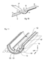
- this abutting edge 2 is not rectilinearly parallel to the pivot axis 1, but is semicircular (see. Fig. 19 ) educated.
- the Tieback 27 has a substantially greater width than thickness parallel to the pivot axis 1.
- an elasticity and flexibility of the tension band 27 are ensured during the rotation of the second jaw part 10 '.
- the tension band 27 has a relatively high rigidity, so that thrust forces can also be generated.
- a first end of the tension band 27 is in operative connection with the handle 110 and can be moved by means of a control device provided thereon.
- the described embodiment of the tubular shaft instrument has a much larger lever, by means of which the second jaw part 10 'can be moved via the drawstring 27.
- the two jaw parts 10, 10 'each have a clamping surface 12, 12'.
- the first jaw part 10 thus has at a distal portion an upwardly facing first clamping surface 12.
- This first clamping surface 12 is formed substantially concave transversely to the longitudinal axis of the first jaw part 10.
- the convex second clamping surface 12 'of the second jaw part 10' lies substantially parallel to this first clamping surface 12.
- these clamping surfaces 12, 12 ' are not only suitable for securely fixing the tissue to be cut later, but also form the electrodes for a coagulation process.
- portions of the clamping surfaces 12, 12 ' are electrically conductive and connected via interconnects with an RF power source, which is also controllable via the handle 110.
- an RF power source which is also controllable via the handle 110.
- the collected tissue can be so much desolate that the severing without bleeding is possible.
- At least sections of the jaw parts 10, 10 ' are produced by injection molding from ceramic.
- the guide elements, in particular the joint guide rails 41, 41 'and the joint guide pins 42, 42' of the joint 40 can be easily formed.
- the ceramic joint 40 forms an electrical insulation between the jaw parts 10, 10 ', in particular between their electrodes for coagulation.
- a cutting device 50 is moved parallel to a fixing plane xy (cf. Fig. 11 ), which is determined by the clamping surfaces 12, 12 '.
- This cutting device 50 comprises a cutting edge 51 for severing the tissue and a guide wire 52 by means of which a movement of the cutting edge 51 in the longitudinal direction of the tubular shaft instrument (x-axis) is possible.
- the cutting edge 51 is retracted so far towards the tubular shaft 24 that premature injury to the tissue is not possible.
- the cutting edge is located in the first jaw part 10 at the height of the hinge guide pins 42, 42 '. From this initial position, the cutting edge 51 is connected to a ramp 55 integrated in the second jaw part 10 '(cf. Fig. 4 ) is supplied to the fixing plane xy. This ramp 55 is located between the two joint guide rails 41, 41 '.
- the second jaw part 10 ' For the movement of the cutting edge 51 or blade, the second jaw part 10 'provides a blade guide 53.
- This blade guide 53 is an elongated opening extending along the longitudinal axis of the second jaw part 10 '.
- the second jaw part 10 ' In order to keep the cutting edge 51 perpendicular to the fixing plane xy, the second jaw part 10 'has in its middle region side parts 60, 60' which are arranged parallel to one another in such a way that they form a longitudinally extending channel. In this channel, the cutting edge 51 or blade is guided.
- the cutting edge 51 After closing the jaw parts 10, 10 ', the cutting edge 51 thus slides from its starting position via the ramp 55 into the said channel and can be pulled or pushed over the tissue in the distal and proximal directions. In order to ensure a gradual separation of the tissue by this movement, the cutting edge 51 is biased relative to the fixing plane xy.
- a biasing means exerts a force perpendicular to the fixing plane xy, which presses the cutting edge 51 against the plane.
- Fig. 12 This force is built on the elasticity of the guide wire 52 and its bending. How out Fig. 12 can be seen, the guide wire 52 in the plane defined by the cutting edge 51 plane, perpendicular to the fixing plane xy, curved. In a front portion of the guide wire 52 is a bead 56.
- the bead 56 is so integrated into the guide wire 52 that when fully extended state of the cutting device 50, so when the blade 52 at the distal end of the jaws 10, 10 'is located , the bead in the tubular shaft 24 is also at the distal end thereof.
- the bead 56 serves to deliver at least part of the force exerted by the curvature of the guide wire 52 perpendicular to the fixing plane xy to the tubular shaft 24 and has corresponding contact points.
- the bending of the guidewire 52 is such that when the proximal end of the guidewire is parallel with the tubular shaft 24, the distal end of the free guidewire 52 is bent downwardly and the cutting edge 51 is at least partially below the fixation plane xy.
- the guide wire 52 is in operative connection with the handle 110 such that by means of this the cutting edge 51 can be reciprocated in the tool head 30.
- the cutting edge 51 has at least one section which runs essentially parallel to the fixing plane xy and thus parallel to the fixed tissue.
- the cutting edge 51 slides during the cutting process over the tissue until it is completely severed.
- the section of the cutting blade formed parallel to the fixing plane xy also has the advantage that the cutting edge 51 not only punctually attaches to the tissue, but usually over a relatively long range. Thus, a punctual wear of the cutting edge 51 is avoided.
- Fig. 13 shows a semicircular cutting edge 51 which has a convex curvature.
- the cutting edge 51 is arranged on the underside of the guide wire 52. It has a cutting curvature 54 in the distal and proximal direction of the tubular shaft instrument.
- Fig. 14 shows a cutting edge 51, which consists of two successively arranged semicircles.
- Fig. 15 shows a cutting edge 51 which has a cutting curvature 54 in the distal direction, and in the proximal direction a portion perpendicular to the guide wire 52.
- the cutting edge 51 has a total of micro-toothing.
- the guide wire 52 is a rail.
- the rail may be formed to have the same functionality as the guide wire 52.
- the bias voltage with respect to the fixing plane xy can be achieved by the intrinsic elasticity of the rail or by a separate device (eg a spring).
- the advantageous cutting device 50 of the invention has hitherto been described in connection with the advantageous articulation. However, both can also be performed separately from each other.
- FIGS. 17 and 18 show the FIGS. 17 and 18 the cutting device 50 in a tool head 30, wherein the second jaw part 10 'is not in operative connection with the first jaw part 10 via a slotted guide.
- the axis of rotation 1 lies here essentially on the longitudinal axis of the jaw parts 10, 10 '.
- the tubular shaft instrument further comprises a cutting control device.
- a cutting control device determines when the tissue between the two clamping surfaces 12, 12 'is completely severed.
- the cutting edge 51 sits on the first clamping surface 12 when the tissue is completely severed. Since the clamping surface 12 comprises an electrode for coagulation, it is at least partially electrically conductive. According to the invention, at least a portion of the cutting edge 51, which mechanically contacts the parting surface 12 in the case of severed tissue, is likewise formed from electrically conductive material. By means of a cutting control device, the electrical contact between the cutting edge 51 and the Clamping surface 12 determined.
- the cutting control device for determining and indicating the progress of the cutting process comprises a processing device 100, a display device 101, a switch 103 and a displacement sensor 102.
- the displacement sensor 102 determines the position or the movement of the cutting edge 51 and thus helps to define an observation interval which preferably comprises a complete cutting movement.
- the switch 103 is formed in the simplest case by the electrically conductive cutting edge 51 and the first clamping surface 12.
- the electrical switch 103 is considered closed only when there is a low-resistance connection between the clamping surface 12 and the cutting edge 51.
- a corresponding device is connected upstream of the processing device 100. If the processing device 100 determines that there is a continuous low-resistance contact between the cutting edge 51 and the clamping surface 12 during a complete observation interval, it indicates to the user by means of the display device 101 that the collected tissue is completely severed. Thus, the cutting device 50 is protected since the movement of the cutting edge 51 over the clamping surface 12 without intervening tissue damages it.
- the user can also be constantly displayed whether there is a direct mechanical contact between the cutting edge 51 and the clamping surface 12. Since the movement of the cutting edge 51 is performed manually by the user, he can independently draw conclusions as to whether the tissue is sufficiently severed.
- the displacement sensor 102 comprises two electrical contact regions at the distal and proximal ends of the blade guide 53, which are designed such that a contact between the cutting edge 51 and the distal contact region and between the cutting edge 51 and the proximal contact region can be determined.
- the processing device 100 can thus detect the beginning and the end of an observation interval.
- the Fig. 20 shows a schematic detail view of the handle 110 from Fig. 1 ,
- the handle 110 includes a handle body 117, on the underside of a first handle lever 122 is integrally formed.
- This handle lever 122 has an opening for receiving a plurality of fingers, preferably the middle, ring and little finger.
- a second handle lever 122 ' is rotatably connected to the handle body 117 near the first handle lever 122.
- the handle levers 122, 122 ' form a manual trigger 120 and can be accommodated in the user's hand so that the entire tubular shaft instrument can be guided with one hand.
- the hand encloses sections of the handle levers 122, 122 '.
- At the end remote from the handle body 117 of the second handle lever 122 ' is an extension 125 which engages in a rack 124.
- This rack 124 is attached at a right angle to the longitudinal axis of the first handle lever 122 at its end facing away from the handle body 117.
- the toothing of the rack 24 is formed such that the second handle lever 122 'can be gradually moved toward the first handle lever 122 and holds the corresponding set position without the permanent application of a force.
- the rack 124 is pushed away from the extension 125 so that they are no longer engaged.
- the handle 110 has a finger trigger 130, which is also rotatably attached to the handle body 117.
- the finger trigger 130 By actuating the finger trigger 130, the cutting device 50, in particular the cutting edge 51, can be moved in the distal direction.
- a spring element, not shown, in the interior of the handle body 117 brings the finger trigger 130 after actuation back to its original position, whereby the cutting device 50 is moved in the proximal direction.
- the finger trigger 130 is arranged distally in front of the first grip lever 122 in such a manner that when the grip lever 122, 122 'is gripped around the finger trigger 130 can be actuated with the index finger.
- the handle 110 has a push button switch 116 on the proximal side of the handle body 117, which serves to control the coagulation current.
- a control device with a plurality of actuating elements can be provided, by means of which a plurality of Coagulation modes can be selected and performed. It is also conceivable to provide the display device 101 on the handle body 117.
- the tubular shaft 24 and handle 110 are formed such that the tubular shaft 24 is releasably inserted into the handle 110.
- a receiving opening 112 on the side of the handle 110 which can be closed by means of a cover.
- a sterile disposable tubular shaft 24 with a corresponding tool head 30 and cutting device 50 is inserted into the reusable handle 110 and locked there. Reuse of the tubular shaft 24 and the associated devices is not provided here.
- the handle body 117 has a first coupling element 114 or coupling element, a second coupling element 114 'or coupling element and a third coupling element 114 "or coupling element A ring provided at the proximal end of the tubular shaft 24 engages such that the tubular shaft is rigidly connected to the handle body 117.
- a first inner tube adapter 22 engages in the first coupling element 114 operatively connected to the second grip lever 122 '
- the movement of the second handle lever 122 ' is transmitted to the first coupling element 114 by a mechanism arranged within the handle body 117 and in turn transmits it to the first inner tube adapter 22.
- the latter is directly or indirectly connected via the tension band 27 the second maul il 10 'in mechanical connection.
- a longitudinal displacement of the first inner tube adapter 22 relative to the tubular shaft 24 thus causes opening and closing of the jaw parts 10, 10 '.
- a second inner tube adapter 22 ' is freely movable relative to the first inner tube adapter 22 in its interior.
- a proximal ring at the end of the second inner tube adapter 22 ' engages the second coupling element 114' and transmits the latter Movement or the force exerted by the finger trigger 130 force to the cutting device 50th
- a removable fixation is provided on this, which holds the réellerohradapter 22, 22 'relative to the tubular shaft 24 in a predetermined position which is designed such that the rings easily in the coupling elements 114, 114 ', 114 "can be used.
- the coupling elements 114, 114 '114 are configured such that the tubular shaft 24 can be rotated relative to the handle 110.
- the alignment of the tool head 30 relative to the handle 110 can be freely adjusted. 22 'and the tubular shaft 24 in the coupling elements 114, 114', 114 "and thus form a hinge.
Description
- Die Erfindung betrifft ein medizinisches Instrument, insbesondere ein Rohrschaftinstrument, zum Schneiden von Gewebe.
- In der modernen Medizin versucht man im Allgemeinen, die Schädigung von intaktem Gewebe so gering wie möglich zu halten. Die minimalinvasive Chirurgie ist daher, wenn es die Umstände erlauben, meist die bevorzugte Art, mit der ein operativer Eingriff durchgeführt wird. Kleine Schnitte und eine geringe Verletzung des Gewebes führen zu einem geringeren Schmerzempfinden nach der Operation und zu einer raschen Erholung und Mobilisation des Patienten. Dies trifft auch für die laparoskopische Chirurgie zu, bei der komplexe Operationen im Bauchraum durchgeführt werden.
- Für die Hersteller von medizinischen Instrumenten, stellen diese Art von Operationen und die dafür benötigten Geräte eine besondere Herausforderung dar, da ein Großteil der operativen Schritte in sehr beschränkten Räumen und ohne direkten Sichtkontakt durchgeführt werden. So müssen sich die verwendeten medizinischen Geräte nicht nur in kleinsten Räumen handhaben lassen, sondern auch so sicher funktionieren, dass eine optische Kontrolle überflüssig ist. Vorzugsweise sind die Instrumente derart beschaffen, dass dem operierenden Arzt auch ohne Sichtkontakt stets eine Rückmeldung zur Verfügung steht, die einen Rückschluss auf den Verlauf der Operation zulässt.
- Dies gilt besonders für sämtliche Instrumente, die sich zum Durchtrennen von Gewebe eignen. Da für die minimalinvasive Chirurgie Skalpelle mit einer offenen Klinge eher ungeeignet sind (vgl. hierzu die
DE 44 44 166 A1 ), greift man häufig auf scherenartige bzw. zangenartige Instrumente mit Maulteilen zurück, die zum einen beim Einführen des Instruments die Klinge abdecken und zum anderen gleichzeitig eine Haltefunktion für das zu schneidende Gewebe übernehmen. Die Klinge wird dann zum Schneiden im Inneren der Maulteile hin- und herbewegt. - Bei den zangenartigen Instrumenten ist die Klinge bzw. das Skalpell meist vollständig durch die zugehörigen Maulteile verdeckt. Es ist daher umso schwieriger, Rückschlüsse zu ziehen, ob das gefasste Gewebe mit einer oder mehreren Schnittbewegungen bereits vollständig durchtrennt wurde. Dieses Wissen ist jedoch für den positiven Verlauf der Operation entscheidend.
- Ein solches Instrument ist aus der
EP 0 717 960 A2 bekannt, aus der die Präambel des Anspruchs 1 abgeleitet wird. - Andererseits kann das übermäßige Bewegen der Klinge, bei bereits durchtrenntem Gewebe, schnell zu einer Abnützung des Instruments führen. Es gilt daher, die Instrumente stets auf ihre Schneidfähigkeit zu kontrollieren und abgenutzte Klingen auszutauschen. Diese Form der Wartung ist nicht nur teuer, sondern auch aufwändig. Häufig ist der Austausch von einzelnen Elementen der Instrumente nicht möglich, weshalb das gesamte Instrument ausgetauscht werden muss.
- Ausgehend von diesem Stand der Technik ist es Aufgabe der vorliegenden Erfindung, ein medizinisches Instrument bereitzustellen, das ein sicheres Durchtrennen von Gewebe gewährleistet und eine lang anhaltende Funktionalität bereit stellt.
- Diese Aufgabe wird durch ein medizinisches Instrument gemäß dem vorliegenden Anspruch 1 gelöst.
- Im Einzelnen wird die Aufgabe durch ein medizinisches Instrument gelöst, das ein erstes und ein zweites Maulteil mit jeweils mindestens einer Klemmfläche zum Fixieren und/oder Positionieren von Gewebe in einer Fixierebene, eine Schneidvorrichtung mit einer Schneide, die zum Schneiden von Gewebe gegenüber einem der Maulteile angeordnet und im Wesentlichen parallel zur Fixierebene über einen vorbestimmten Schneidweg bewegbar ist, eine erste Elektrode und eine zweite Elektrode umfasst, die derart an der Schneidvorrichtung und/oder der Klemmfläche angeordnet sind, dass mittels einer mit den Elektroden verbundenen Verarbeitungseinrichtung eine mechanische Kontaktierung zwischen Schneid- und Klemmfläche feststellbar ist.
- Ein wesentlicher Gedanke der vorliegenden Erfindung besteht also darin, bei einem medizinischen Instrument zum Durchtrennen von Gewebe mittels Elektroden eine mechanische Kontaktierung zwischen einer Schneide und einer zugehörigen Klemmfläche festzustellen. Diese mechanische Kontaktierung kann elektrisch oder mittels eines Schalters festgestellt werden. Die Verarbeitungseinrichtung empfängt die entsprechenden Signale und wertet diese aus.
- In einem bevorzugten Ausführungsbeispiel umfasst die Schneide die erste Elektrode, die Klemmfläche die zweite Elektrode und die Verarbeitungseinrichtung eine Vorrichtung zum Bestimmen eines elektrischen Widerstands zwischen den Elektroden. Die erste Elektrode wird also durch eine elektrisch leitende Schneide oder einen elektrisch leitenden Abschnitt der Schneide gebildet. Die zweite Elektrode ist die elektrisch leitende Klemmfläche oder ein elektrisch leitender Abschnitt der Klemmfläche. Die Verarbeitungseinrichtung misst den elektrischen Widerstand zwischen der ersten und der zweiten Elektrode. Vorzugsweise stellt die Verarbeitungseinrichtung dann fest, dass das unmittelbar unterhalb der Schneide befindliche Gewebe durchtrennt ist, wenn der Widerstand kleiner einem voreingestellten Schwellwert ist. Dies ist nötig, da das zu schneidende Gewebe eine gewisse elektrische Leitfähigkeit besitzt und somit bereits bei undurchtrenntem Gewebe ein hochohmiger Kontaktschluss zwischen der ersten Elektrode und der zweiten Elektrode vorliegt. Durch das Festlegen eines Schwellwerts kann der Kontaktschluss über das zu schneidende Gewebe von einem direkten Kontaktschluss zwischen den beiden Elektroden unterschieden werden. Dieser direkte Kontaktschluss ist Indikator für die mechanische Kontaktierung zwischen Schneide und Klemmfläche.
- Vorzugsweise ist die Verarbeitungseinrichtung derart ausgebildet, dass ein Verlauf des Widerstands während des Schneidwegs feststellbar ist. Der Schneidweg definiert für die Verarbeitungseinrichtung ein Beobachtungsintervall und kann beispielsweise eine Hin- und Herbewegung der Schneide zwischen einem distalen und proximalen Abschnitt der Maulteile umfassen.
- Es ist möglich, die Bewegung der Schneide manuell zu erfassen. So kann ein mechanischer Anschlag bei der Bewegung der Schneide mit einer Betätigungseinrichtung Aufschluss über die zurückgelegte Wegstrecke bzw. den zurückgelegten Schneidweg geben. Vorzugsweise umfasst die Verarbeitungseinrichtung einen Wegsensor und/oder elektrischen Schalter zur Erfassung der Bewegung der Schneide parallel zur Klemmfläche. Die besagte Schneidvorrichtung ist derart ausgebildet, dass sie sich entlang einer Längsachse des medizinischen Instruments parallel zur Klemmfläche hin- und herbewegen lässt. Die Schneide sollte also vorzugsweise das Gewebe nicht nur an einem Punkt durchtrennen, sondern über einen Schnittbereich entlang besagter Längsbewegung. Zur effektiven Bestimmung, ob das Gewebe in diesem Bereich vollständig durchtrennt ist, ist es vorteilhaft, die Bewegung der Schneide über ein Beobachtungsintervall bzw. eine Beobachtungsstrecke zu erfassen und zu bestimmen, ob ein durchgehender mechanischer Kontakt zwischen Schneide und Klemmfläche vorliegt. Die Bewegung der Schneide lässt sich entweder direkt mittels eines Wegsensors feststellen, oder es kann mittels Schaltern am Ende des Schnittbereichs indirekt festgestellt werden, ob die Schneide von einem ersten Schalter zu einem zweiten Schalter bewegt wurde. Auch hier gilt das Gewebe erst dann als vollständig durchtrennt, wenn innerhalb des gesamten Intervalls bzw. während des gesamten Schneidwegs, also von einer Bewegung der Schneide vom ersten Schalter zum zweiten Schalter ein mechanischer bzw. elektrischer, insbesondere niederohmiger Kontakt zwischen Schneide und Klemmfläche vorliegt.
- Vorzugsweise umfassen die beiden Maulteile jeweils eine Koagulationselektrode zur Koagulation des fixierten Gewebes. Somit kann das Gewebe mittels eines Hochfrequenzstroms koaguliert werden, bevor ein mechanisches Durchtrennen mittels der Schneide stattfindet. Ein sicherer Gefäßverschluss vor der mechanischen Durchtrennung wird gewährleistet. Des Weiteren kann eine der beiden Koagulationselektroden mit der Verarbeitungseinrichtung verbunden sein und somit zur Bestimmung der mechanischen Kontaktierung herangezogen werden. Zur Bildung der Koagulationselektroden sind die Maulteile entweder zumindest teilweise elektrisch leitend oder weisen eine elektrisch leitfähige Schicht an der dem Gewebe zugewandten Seite auf.
- Vorzugsweise umfasst das mindestens eine Maulteil eine Klingenführung. Die Klingenführung dient zur Stabilisation der Schneide bei der Schneidbewegung. Des Weiteren kann die Klingenführung besagte Schalter oder Wegsensoren aufweisen, um die Bewegung der Schneide festzustellen.
- Vorzugsweise weist das medizinische Instrument Mittel zur Abgabe eines Signals auf, das dann abgegeben wird, wenn der Widerstand über dem gesamten Schneidweg einen vorbestimmten Minimalwert unterschreitet. Diese Form der Anzeige kann also nicht nur dazu genutzt werden, den Widerstand und damit den Fortschritt beim Durchtrennen von Gewebe an einem Punkt bzw. an einer Position der Schneide festzustellen, sondern auch um ein komplettes Durchtrennen des Gewebes über den gesamten Schneideweg.
- Nachfolgend wird die Erfindung anhand von Ausführungsbeispielen beschrieben, die mittels Abbildungen näher erläutert werden. Hierbei zeigen:
- - Fig. 1
- ein Rohrschaftinstrument zum Durchtrennen von Gewebe;
- - Fig. 2
- den Werkzeugkopf des Rohrschaftinstruments aus
Fig. 1 , umfassend ein erstes und ein zweites Maulteil; - - Fig. 3
- das zweite Maulteil in einer perspektivischen Seitenansicht;
- - Fig. 4
- das zweite Maulteil in einer Draufsicht;
- - Fig. 5
- das zweite Maulteil in einer Seitenansicht;
- - Fig. 6
- das erste Maulteil in einer perspektivischen Seitenansicht;
- - Fig. 7
- das erste Maulteil in einer Draufsicht;
- - Fig. 8
- das erste Maulteil in einer Seitenansicht;
- - Fig. 9
- eine schematische Darstellung zweier unterschiedlicher Drehgelenke;
- - Fig. 10
- ein Querschnitt durch den Werkzeugkopf aus
Fig. 2 mit einer Schneidvorrichtung; - - Fig. 11
- eine schematische Darstellung der Schneidvorrichtung;
- - Fig. 12
- eine schematische Darstellung der Schneidvorrichtung in einem Rohrschaft eines Rohrschaftinstruments;
- - Fig. 13-15
- drei Ausführungsformen einer Schneidklinge;
- - Fig. 16
- ein Blockdiagramm einer Schnittkontrollvorrichtung;
- - Fig. 17
- eine perspektivische Ansicht eines Werkzeugkopfs in einer geöffneten Stellung;
- - Fig. 18
- den Werkzeugkopf aus
Fig. 17 in einer geschlossenen Stellung; - - Fig. 19
- das zweite Maulteil mit Zugband; und
- - Fig. 20
- eine schematische Seitenansicht des Rohrschaftinstruments.
- In der nachfolgenden Beschreibung werden für gleiche und gleich wirkende Teile dieselben Bezugsziffern verwendet.
- Die
Fig. 1 gibt einen groben Überblick über eine Ausführungsform eines erfindungsgemäßen Rohrschaftinstruments. Sie zeigt drei funktionale Komponenten des Rohrschaftinstruments, einen Handgriff 110, einen länglichen Rohrschaft 24 und einen am distalen Ende des Rohrschafts 24 angeordneten Werkzeugkopf 30. Der Werkzeugkopf 30 stellt die eigentliche Funktionalität des Rohrschaftinstruments bereit. Er dient zum Schneiden und/oder Koagulieren von Gewebe. Der Handgriff 110 steuert die Bewegung des Werkzeugkopfs 30. Insbesondere können mittels des Handgriffs 110 Maulteile 10, 10' (vgl.Fig. 2 ) zum Fixieren, Koagulieren und Schneiden von Gewebe geschlossen sowie geöffnet werden. - Die
Fig. 2 zeigt eine Ausführungsform eines erfindungsgemäßen Werkzeugkopfs 30, der ein erstes Maulteil 10 und ein zweites Maulteil 10' umfasst. Das erste Maulteil 10 ist ein länglicher Körper, der an seiner dem Rohrschaft 24 zugewandten Seite einen Adapter 25 aufweist, der starr mit dem Rohrschaft 24 verbunden ist. Über ein Gelenk 40 ist das zweite Maulteil 10' an dem ersten Maulteil 10 befestigt und kann aus einer geöffneten Stellung zum Ergreifen des Gewebes in eine geschlossene Stellung zum Fixieren des Gewebes gebracht werden. Das Gelenk 40 ist derart ausgebildet, dass sich eine virtuelle Drehgelenksachse 1 bzw. Drehachse außerhalb des ersten und zweiten Maulteils 10, 10' befindet. Anders als bei herkömmlichen Gelenken 40 für derartige Instrumente liegt also die Drehgelenksachse 1 nicht in dem Bereich, in dem die Maulteile 10, 10' ineinander eingreifen, oder im Rohrschaft 24, nahe der Längsachse des Rohrschafts 24. Die Mechanik des dargestellten Gelenks 40 wirkt so, dass sich eine virtuelle Drehgelenksachse 1 oberhalb der dem zweiten Maulteil 10' zugewandten Seite des Rohrschaftinstruments ausbildet. - Die besonderen Vorteile einer solchen ausgelagerten Drehgelenksachse 1 zeigen sich anhand der schematischen Darstellungen der
Fig. 9 . In der oberen linken Ecke ist dort ein herkömmliches Drehgelenk abgebildet, dessen Drehgelenksachse 1 im Wesentlichen auf den Längsachsen der Maulteile 10 und 10' liegt. Im geöffneten Zustand ist die Spitze 16' des zweiten Maulteils 10' gegenüber der Spitze 16 des ersten Maulteils 10 zurückversetzt. Anders verhält es sich jedoch bei dem erfindungsgemäßen Gelenk 40, das schematisch in den anderen beiden Abbildungen derFig. 9 gezeigt wird. Hier befindet sich die Drehgelenksachse 1 deutlich oberhalb der Längsachsen der beiden länglichen Maulteile 10, 10'. Bei gleicher Öffnung hinsichtlich des Winkels, den das erste Maulteil 10 zum zweiten Maulteil 10' ausbildet, liegt die Spitze 16' des zweiten Maulteils 10' auch im geöffneten Zustand im Wesentlichen auf bzw. vor einer Lotgeraden durch die Spitze 16 des ersten Maulteils 10. Öffnet man das zweite Maulteil 10' gegenüber dem ersten Maulteil 10, kommt es also nicht nur zu einer Drehbewegung, bei der sich die relative Ausrichtung des zweiten Maulteils 10' zum ersten Maulteil 10 verändert, sondern auch zu einer Längsverschiebung des zweiten Maulteils 10', die in distaler Richtung, also parallel zur Längsachse des ersten Maulteils 10 in Richtung dessen Spitze 16 orientiert ist. Umgekehrt kommt es bei einer Schließbewegung der Maulteile 10, 10' zu einer Längsverschiebung des zweiten Maulteils 10' in proximaler Richtung. Hierdurch wird Gewebe, das sich zwischen den beiden Maulteilen 10, 10' befindet, im Endeffekt in den Werkzeugkopf 30 hineingezogen. Des Weiteren ist erfindungsgemäß der Hub der zweiten Spitze 16, also die Distanz zwischen der ersten und der zweiten Spitze 16, 16' bei gleichem Öffnungswinkel wesentlich größer (vgl.Fig. 9 , rechts). In einem Ausführungsbeispiel verhält sich die Länge der Maulteile 10, 10' zur Distanz der Längsachse des ersten Maulteils 10 zur Drehgelenksachse ca. im Verhältnis 10:1. - Während in der
Fig. 9 die ausgelagerte Drehgelenksachse 1 zur Verdeutlichung über senkrecht an die proximalen Enden der Maulteile 10, 10' ansetzende Verlängerungen erzielt wird, ist in einer bevorzugten Ausführungsform die Drehgelenksachse 1 rein virtuell ausgebildet. Diese virtuelle Ausbildung wird durch eine Kulissenführung, wie sie im Weiteren anhand derFig. 3-8 erläutert wird, erzielt. So weist, wie inFig. 3 dargestellt, das zweite Maulteil 10' an seinem proximalen Ende gegenüber der Spitze 16' zwei gebogene Gelenkführungsschienen 41, 41' auf. Aus einer Draufsicht betrachtet (vgl.Fig. 4 ) verlaufen diese Gelenkführungsschienen 41, 41' im Wesentlichen parallel entlang der Längsachse des zweiten Maulteils 10' und sind voneinander zur Bildung eines Kanals beabstandet. - Von der Seite betrachtet (vgl.
Fig. 5 ) weist das zweite Maulteil 10' ein löffelförmiges Profil auf. Das proximale Ende des zweiten Maulteils 10', insbesondere die Gelenkführungsschienen 41, 41', weisen also an ihrer Oberseite jeweils einen konkaven Abschnitt 43, 43' auf, der mit dem ersten Maulteil 10 in Eingriff steht. Wie anhand derFig. 6 ersichtlich, weist hierfür das erste Maulteil 10 zwei Gelenkführungszapfen 42, 42' auf, die jeweils über einen konvexen Strukturabschnitt verfügen. Bei der Öffnungs- und Schließbewegung der Maulteile 10, 10' gleitet also der konkave Abschnitt 43 der ersten Gelenkführungsschiene 41 über den benachbarten, konvexen Abschnitt des ersten Gelenkführungszapfens 42 und der konkave Abschnitt 43' der zweiten Gelenkführungsschiene 41' über den benachbarten, konvexen Abschnitt des zweiten Gelenkführungszapfens 42'. Die Krümmung der konkaven Abschnitte 43, 43' der beiden Gelenkführungsschienen 41, 41' sowie der korrespondierenden Abschnitte der Gelenkführungszapfen 42, 42' sind maßgeblich für die Position der virtuellen Drehgelenksachse 1. Bei einer stärkeren Krümmung ist die Drehgelenkachse 1 näher beim Werkzeugkopf 30 gelegen als bei einer schwachen Krümmung. Entsprechend stark und schwach treten die hinsichtlich derFig. 9 beschriebenen Effekte auf. - Das Führungsgetriebe bzw. Gelenk 40 hat gegenüber Gelenken, die lediglich eine punktuelle Verbindung aufweisen, des Weiteren den Vorteil einer hohen Stabilität. Durch die konvexen und konkaven Abschnitte, die in einander eingreifen, wird ein großflächiger Kontaktbereich ausgebildet und das Gelenk 40 kann wesentlich mehr Kraft aufnehmen, als ein Gelenk mit einer punktuellen Verbindung. Zur weiteren Stabilisierung des Gelenks 40 umfasst das erste Maulteil 10 ein erstes Gelenkführungslager 46 und ein zweites Gelenkführungslager 46'. Wie die Gelenkführungszapfen 42, 42' sind die Gelenklager 46, 46' wechselseitig an der Innenseite der Seitenwände des ersten Maulteils 10 angebracht.
- Das erste Gelenkführungslager 46 und der erste Führungszapfen 42 sind derart voneinander beabstandet, dass sie in ihrem Zwischenraum die erste Gelenkführungsschiene 41 aufnehmen. Das erste Gelenkführungslager 46 weist einen konkaven Schnitt auf, der mit einem konvexen Abschnitt 44 der ersten Gelenkführungsschiene 41 in Eingriff steht. Beim Öffnen und Schließen des Werkzeugkopfs 30 rotiert die erste Gelenkführungsschiene 41, geführt von dem ersten Führungszapfen 42 und dem ersten Gelenkführungslager 46 um die Drehgelenksachse 1.
- Ebenso rotiert die zweite Gelenkführungsschiene 41', geführt von dem zweiten Führungszapfen 42' und dem zweiten Gelenkführungslager 46' um die Drehgelenksachse 1. Hierfür sind die zweite Gelenkführungsschiene 41', der zweite Gelenkführungszapfen 42', ein konvexer Abschnitt 44' der zweiten Gelenkführungsschiene 41' und das zweite Gelenkführungslager 46' symmetrisch zu der ersten Gelenkführungsschiene 41, dem ersten Gelenkführungszapfen 42, dem konvexen Abschnitt 44 der ersten Gelenkführungsschiene 41 und dem ersten Gelenkführungslager 46 ausgebildet und angeordnet.
- Wie in der
Fig. 10 gezeigt, setzt ein Zugband 27 am proximalen Ende des zweiten Maulteils 10' an. Genauer gesagt, ist es ungefähr mittig an den konvexen Abschnitten 44, 44' der Gelenkführungsschienen 41, 41' angebracht. Hierfür weisen die Gelenkführungsschienen 41, 41' ein Profil zum Bilden einer Stoßkante 2 (Fig. 5 ) auf. Vorzugsweise verläuft diese Stoßkante 2 nicht geradlinig parallel zur Drehgelenkachse 1, sondern ist halbkreisförmig (vgl.Fig. 19 ) ausgebildet. Durch diese verlängerte Stoßkante 2, entlang der das zweite Maulteil 10' und das Zugband 27 verschweißt sind, sind die Krafteinleitung in das Zugband 27 homogenisiert, und die Zug- und Biegebelastbarkeit der Schweißnaht deutlich erhöht. In alternativen Ausführungsformen sind spitzwinklige Schweißnähte oder mehrfach gezackte Schweißnähte denkbar, die ein vergleichbares Ergebnis liefern. Das Zugband 27 weist parallel zur Drehgelenksachse 1 eine wesentlich größere Breite als Dicke auf. Somit sind eine Elastizität und Biegbarkeit des Zugbands 27 bei der Rotation des zweiten Maulteils 10' gewährleistet. In Längsrichtung des Rohrschaftinstruments weist das Zugband 27 jedoch eine relativ hohe Steifigkeit auf, so dass auch Schubkräfte erzeugt werden können. - Durch das Ansetzen eines ersten Endes des Zugbands 27 an die konvexen Abschnitte 44, 44' der Gelenkführungsschienen 41, 41' wird sichergestellt, dass die Zugkraft, die mittels des Zugbands 27 ausgeübt wird, immer im wesentlichen tangential zur Kreisbewegung der gekrümmten Gelenkführungsschienen 41, 41' um die Drehgelenksachse 1 wirkt. Somit ist eine einheitliche, vom Öffnungswinkel unabhängige Kräfteübertragung sichergestellt. Ein zweites Ende des Zugbands 27 steht mit dem Handgriff 110 in Wirkverbindung und lässt sich mittels einer an diesem vorgesehenen Steuervorrichtung bewegen. Wegen der virtuellen Drehgelenksachse 1, die sich, wie bereits erläutert, außerhalb und oberhalb der Maulteile 10, 10' befindet, ist die Distanz zwischen der Drehgelenksachse 1 und dem ersten Ende des Zugbands 27 deutlich größer als die Distanz, die bei üblichen Gelenken erzielt wird. Daher besitzt die beschriebene Ausführungsform des Rohrschaftinstruments einen wesentlich größeren Hebel, mittels dessen das zweite Maulteil 10' über das Zugband 27 bewegt werden kann.
- Zum Fixieren des Gewebes weisen die beiden Maulteile 10, 10' jeweils eine Klemmfläche 12, 12' auf. Das erste Maulteil 10 weist also an einem distalen Abschnitt eine nach oben gewandte erste Klemmfläche 12 auf. Diese erste Klemmfläche 12 ist quer zur Längsachse des ersten Maulteils 10 im Wesentlichen konkav ausgebildet. Im geschlossenen Zustand des Werkzeugkopfs 30 liegt die konvexe zweite Klemmfläche 12' des zweiten Maulteils 10' im Wesentlichen parallel zu dieser ersten Klemmfläche 12.
- Im beschriebenen Ausführungsbeispiel sind diese Klemmflächen 12, 12' nicht nur dazu geeignet, das später zu schneidende Gewebe sicher zu fixieren, sondern bilden auch die Elektroden für einen Koagulationsvorgang. Hierfür sind Abschnitte der Klemmflächen 12, 12' elektrisch leitend und über Leiterbahnen mit einer HF-Stromquelle verbunden, die ebenfalls über den Handgriff 110 steuerbar ist. Somit kann vor dem Schneidvorgang das gefasste Gewebe so stark verödet werden, dass das Durchtrennen ohne eine Blutung möglich ist. Es werden zumindest Abschnitte der Maulteile 10, 10' im Spritzgussverfahren aus Keramik hergestellt. Somit lassen sich die Führungselemente, insbesondere die Gelenkführungsschienen 41, 41' und die Gelenkführungszapfen 42, 42' des Gelenks 40 einfach ausbilden. Das Gelenk 40 aus Keramik bildet eine elektrische Isolation zwischen den Maulteilen 10, 10', insbesondere zwischen deren Elektroden zur Koagulation.
- Nach der Koagulation erfolgt im vorliegenden Ausführungsbeispiel der eigentliche mechanische Schneidvorgang. Hierfür wird parallel zu einer Fixierebene x-y (vgl.
Fig. 11 ), die durch die Klemmflächen 12, 12' bestimmt wird, eine Schneidvorrichtung 50 bewegt. Diese Schneidvorrichtung 50 umfasst eine Schneide 51 zum Durchtrennen des Gewebes sowie einen Führungsdraht 52 mittels dessen eine Bewegung der Schneide 51 in Längsrichtung des Rohrschaftinstruments (x-Achse) möglich ist. - Vor dem Schneidvorgang ist die Schneide 51 so weit zum Rohrschaft 24 hin zurückgezogen, dass eine vorzeitige Verletzung des Gewebes nicht möglich ist. Vorzugsweise befindet sich die Schneide im ersten Maulteil 10 auf der Höhe der Gelenkführungszapfen 42, 42'. Aus dieser Ausgangsposition wird die Schneide 51 über eine in das zweite Maulteil 10' integrierte Rampe 55 (vgl. hierzu
Fig. 4 ) auf die Fixierebene x-y zugeführt. Diese Rampe 55 befindet sich zwischen den beiden Gelenkführungsschienen 41, 41'. Für die Bewegung der Schneide 51 bzw. Klinge stellt das zweite Maulteil 10' eine Klingenführung 53 bereit. Diese Klingenführung 53 ist eine längliche Öffnung, die sich längs der Längsachse des zweiten Maulteils 10' erstreckt. Um die Schneide 51 senkrecht zur Fixierebene x-y zu halten, weist das zweite Maulteil 10' in seinem Mittelbereich Seitenteile 60, 60' auf, die derart parallel zu einander angeordnet sind, dass sie einen sich längs erstreckenden Kanal bilden. In diesem Kanal wird die Schneide 51 bzw. Klinge geführt. - Nach dem Schließen der Maulteile 10, 10' gleitet die Schneide 51 also aus ihrer Ausgangsposition über die Rampe 55 in den besagten Kanal und kann dort in distale und proximale Richtung über das Gewebe gezogen bzw. geschoben werden. Um durch diese Bewegung eine schrittweise Durchtrennung des Gewebes zu gewährleisten, ist die Schneide 51 gegenüber der Fixierebene x-y vorgespannt. Eine Vorspanneinrichtung übt eine Kraft senkrecht zur Fixierebene x-y aus, die die Schneide 51 gegen die Ebene drückt.
- Diese Kraft wird über die Elastizität des Führungsdrahts 52 und dessen Biegung aufgebaut. Wie aus
Fig. 12 ersichtlich, ist der Führungsdraht 52 in der von der Schneide 51 aufgespannten Ebene, senkrecht zur Fixierebene x-y, gekrümmt. In einem vorderen Abschnitt des Führungsdrahts 52 befindet sich eine Sicke 56. Die Sicke 56 ist derart in den Führungsdraht 52 integriert, dass sich bei vollständig ausgefahrenen Zustand der Schneidvorrichtung 50, also wenn sich die Schneide 52 am distalen Ende der Maulteile 10, 10' befindet, die Sicke im Rohrschaft 24 ebenfalls am distalen Ende dessen ist. Die Sicke 56 dient dazu, zumindest einen Teil der durch die Krümmung des Führungsdrahts 52 ausgeübten Kraft senkrecht zur Fixierebene x-y an den Rohrschaft 24 abzugeben und weist entsprechende Kontaktpunkte auf. Die Biegung des Führungsdrahts 52 ist so beschaffen, dass bei einem Parallelverlaufen des proximalen Endes des Führungsdrahts mit dem Rohrschaft 24 das distale Ende des freien Führungsdrahts 52 nach unten gebogen ist und die Schneide 51 zumindest teilweise unterhalb der Fixierebene x-y liegt. Der Führungsdraht 52 steht mit dem Handgriff 110 derart in Wirkverbindung, dass mittels diesem die Schneide 51 im Werkzeugkopf 30 hin- und herbewegt werden kann. - Hinsichtlich der Ausbildung der Schneide 51 sind verschiedenste Ausführungsformen denkbar. Diese werden im Weiteren anhand der
Fig. 13, 14 und 15 beschrieben. Ein Gedanke der Erfindung besteht darin, dass die Schneide 51 mindestens einen Abschnitt aufweist, der im Wesentlichen parallel zur Fixierebene x-y und somit parallel zum fixierten Gewebe verläuft. Somit gleitet die Schneide 51 beim Schneidvorgang so lange über das Gewebe hinweg, bis dieses vollständig durchtrennt ist. Anders als bei herkömmlichen Schneidvorgängen kann so sichergestellt werden, dass selbst bei abgestumpfter Schneide 51 das Gewebe durchtrennt wird und nicht aufgrund des mechanischen Druckes zerquetscht wird. Der parallel zur Fixierebene x-y ausgebildete Abschnitt der Schneidklinge hat ebenfalls den Vorteil, dass die Schneide 51 nicht nur punktuell auf dem Gewebe ansetzt, sondern meist über einen längeren Bereich. Somit wird ein punktuelles Abnützen der Schneide 51 vermieden. -
Fig. 13 zeigt eine halbkreisförmige Schneide 51, die eine konvexe Krümmung aufweist. Die Schneide 51 ist an der Unterseite des Führungsdrahts 52 angeordnet. Sie weist eine Schneidenkrümmung 54 in distaler und proximaler Richtung des Rohrschaftinstruments auf. -
Fig. 14 zeigt eine Schneide 51, die aus zwei jeweils hintereinander angeordneten Halbkreisen besteht. -
Fig. 15 zeigt eine Schneide 51, die in distaler Richtung eine Schneidenkrümmung 54 aufweist, und in proximaler Richtung einen zum Führungsdraht 52 senkrechten Abschnitt. - Die Schneide 51 weist insgesamt eine Mikroverzahnung auf.
- In einem alternativen Biespiel (vgl. beispielsweise
Fig. 10 ) handelt es sich bei dem Führungsdraht 52 um eine Schiene. Die Schiene kann derart ausgebildet sein, dass sie die gleiche Funktionalität wie der Führungsdraht 52 besitzt. Die Vorspannung gegenüber der Fixierebene x-y kann durch die Eigenelastizität der Schiene oder durch eine getrennte Vorrichtung (z.B. eine Feder) erreicht werden. - Die vorteilhafte Schneidvorrichtung 50 der Erfindung wurde bisher in Verbindung mit der vorteilhaften Gelenkausprägung beschrieben. Beides lässt sich jedoch auch getrennt von einander ausführen.
- So zeigen beispielsweise die
Fig. 17 und 18 die Schneidvorrichtung 50 in einem Werkzeugkopf 30, wobei das zweite Maulteil 10' nicht über eine Kulissenführung mit dem ersten Maulteil 10 in Wirkverbindung steht. Die Drehachse 1 liegt hier im Wesentlichen auf der Längsachse der Maulteile 10, 10'. - In einem erfindungsgemäßen Ausführungsbeispiel umfasst das Rohrschaftinstrument des Weiteren eine Schnittkontrollvorrichtung. Diese bestimmt, wann das Gewebe zwischen den beiden Klemmflächen 12, 12' vollständig durchtrennt ist. Bei dem Ausführungsbeispiel sitzt die Schneide 51 bei vollständig durchtrenntem Gewebe auf der ersten Klemmfläche 12 auf. Da die Klemmfläche 12 eine Elektrode zur Koagulation umfasst, ist sie zumindest abschnittsweise elektrisch leitend. Erfindungsgemäß ist zumindest ein Abschnitt der Schneide 51, der bei durchtrenntem Gewebe die Trennfläche 12 mechanisch kontaktiert, ebenfalls aus elektrisch leitendem Material ausgebildet. Mittels einer Schnittkontrollvorrichtung wird der elektrische Kontakt zwischen der Schneide 51 und der Klemmfläche 12 bestimmt. Das gefasste Gewebe gilt als vollständig durchtrennt, wenn bei einer kompletten Schnittbewegung von der Spitze 16' des zweiten Maulteils 10' bis zur Rampe 55 ein durchgehender elektrischer Kontakt zwischen Schneide 51 und Klemmfläche 12 besteht. Wie aus
Fig. 16 ersichtlich, umfasst die Schnittkontrollvorrichtung zur Bestimmung sowie zur Anzeige des Fortschrittes des Schneidvorgangs eine Verarbeitungseinrichtung 100, eine Anzeigevorrichtung 101, einen Schalter 103 und einen Wegsensor 102. Der Wegsensor 102 bestimmt Position bzw. die Bewegung der Schneide 51 und hilft somit, ein Beobachtungsintervall zu definieren, das vorzugsweise eine komplette Schneidenbewegung umfasst. Der Schalter 103 wird im einfachsten Fall durch die elektrisch leitende Schneide 51 sowie die erste Klemmfläche 12 ausgebildet. Da das zu schneidende Gewebe eine gewisse elektrische Leitfähigkeit aufweist, gilt der elektrische Schalter 103 erst dann als geschlossen, wenn eine niederohmige Verbindung zwischen der Klemmfläche 12 und der Schneide 51 besteht. Eine entsprechende Vorrichtung ist der Verarbeitungsvorrichtung 100 vorgeschaltet. Stellt die Verarbeitungseinrichtung 100 fest, dass während eines kompletten Beobachtungsintervalls ein durchgehender niederohmiger Kontakt zwischen Schneide 51 und Klemmfläche 12 vorliegt, so zeigt sie dem Benutzer mittels der Anzeigevorrichtung 101 an, dass das gefasste Gewebe gänzlich durchtrennt ist. Somit wird die Schneidvorrichtung 50 geschont, da die Bewegung der Schneide 51 über die Klemmfläche 12 ohne dazwischen liegendes Gewebe diese schädigt. - Alternativ kann dem Benutzer auch stetig angezeigt werden, ob eine direkte mechanische Kontaktierung zwischen Schneide 51 und Klemmfläche 12 vorliegt. Da die Bewegung der Schneide 51 durch den Benutzer manuell durchgeführt wird, kann er selbstständig Rückschlüsse ziehen, ob das Gewebe ausreichend durchtrennt ist.
- In einem weiteren Ausführungsbeispiel umfasst der Wegsensor 102 zwei elektrische Kontaktbereiche am distalen und proximalen Ende der Klingenführung 53, die derart ausgebildet sind, dass eine Kontaktierung zwischen der Schneide 51 und dem distalen Kontaktbereich sowie zwischen der Schneide 51 und dem proximalen Kontaktbereich bestimmt werden kann. Die Verarbeitungsvorrichtung 100 kann somit den Beginn und das Ende eines Beobachtungsintervalls erfassen.
- Die
Fig. 20 zeigt eine schematische Detailansicht des Handgriffs 110 ausFig. 1 . Der Handgriff 110 umfasst einen Handgriffkörper 117, an dessen Unterseite ein erster Griffhebel 122 integral ausgebildet ist. Dieser Griffhebel 122 weist eine Öffnung zur Aufnahme mehrerer Finger, vorzugsweise des Mittel-, Ring- und kleinen Fingers auf. Ein zweiter Griffhebel 122' ist nahe beim ersten Griffhebel 122 drehbeweglich mit dem Handgriffkörper 117 verbunden. Durch eine Bewegung des zweiten Griffhebels 122' relativ zum ersten Griffhebel 122 in proximale und distale Richtung, lassen sich die Maulteile 10, 10' des Werkzeugkopfs 30 öffnen und schließen. Die Griffhebel 122, 122' bilden einen Handabzug 120 und lassen sich so in der Hand des Benutzers aufnehmen, dass das gesamte Rohrschaftinstrument einhändig geführt werden kann. Hierfür umschließt die Hand Abschnitte der Griffhebel 122, 122'. An dem dem Handgriffkörper 117 abgewandten Ende des zweiten Griffhebels 122' befindet sich ein Fortsatz 125, der in eine Zahnstange 124 einrastet. Diese Zahnstange 124 ist in einem rechten Winkel zur Längsachse des ersten Griffhebels 122 an dessen dem Handgriffkörper 117 abgewandten Ende befestigt. Die Bezahnung der Zahnstange 24 ist derart ausgebildet, dass sich der zweite Griffhebel 122' schrittweise zum ersten Griffhebel 122 hinbewegen lässt und die entsprechende eingestellte Position ohne das permanente Ausüben einer Kraft hält. Um diese Fixierung der Griffhebel 122, 122' zueinander zu lösen, wird die Zahnstange 124 derart von dem Fortsatz 125 weggedrückt, dass diese nicht mehr in Eingriff stehen. - Des Weiteren weist der Handgriff 110 einen Fingerabzug 130 auf, der ebenfalls drehbeweglich an dem Handgriffkörper 117 befestigt ist. Durch die Betätigung des Fingerabzugs 130 kann die Schneidvorrichtung 50, insbesondere die Schneide 51, in distale Richtung bewegt werden. Ein nicht gezeigtes Federelement im Inneren des Handgriffkörpers 117 bringt den Fingerabzug 130 nach der Betätigung zurück in seine Ausgangsposition, wodurch die Schneidvorrichtung 50 in proximaler Richtung bewegt wird. Der Fingerabzug 130 ist distal vor dem ersten Griffhebel 122 derart angeordnet, dass bei einem Umgreifen der Griffhebel 122, 122' der Fingerabzug 130 mit dem Zeigefinger betätigbar ist.
- Der Handgriff 110 weist einen Tastschalter 116 an der proximalen Seite des Handgriffkörpers 117 auf, der zur Steuerung des Koagulationsstroms dient. In einem alternativen Ausführungsbeispiel kann an Stelle des Tastschalters 116 eine Steuereinrichtung mit mehreren Betätigungselementen vorgesehen werden, mittels derer eine Vielzahl von Koagulationsmodi ausgewählt und durchgeführt werden können. Denkbar ist es ebenfalls, die Anzeigevorrichtung 101 am Handgriffkörper 117 vorzusehen.
- Rohrschaft 24 und Handgriff 110 sind derart ausgebildet, dass der Rohrschaft 24 lösbar in den Handgriff 110 einlegbar ist. Hierfür befindet sich seitlich des Handgriffs 110 eine Aufnahmeöffnung 112, die mittels einer Abdeckung verschlossen werden kann.
- Vor der Operation wird also ein steriler Einmal-Rohrschaft 24 mit entsprechendem Werkzeugkopf 30 und Schneidvorrichtung 50 in den wiederverwendbaren Handgriff 110 eingelegt und dort verriegelt. Ein Wiederverwenden des Rohrschafts 24 und der zugehörigen Vorrichtungen ist hier nicht vorgesehen. Zur mechanischen Anbindung des Werkzeugskopfs 30, der Schneidvorrichtung 51 und des Rohrschafts 24 weist der Handgriffkörper 117 ein erstes Kupplungselement 114 bzw. Kopplungselement, ein zweites Kupplungselement 114' bzw. Kopplungselement und ein drittes Kupplungselement 114" bzw. Kopplungselement auf. In das dritte Kupplungselement 114' greift ein an dem proximalen Ende des Rohrschafts 24 vorgesehener Ring derart ein, dass der Rohrschaft starr mit dem Handgriffkörper 117 verbunden ist. In das erste Kupplungselement 114, das mit dem zweiten Griffhebel 122' in Wirkverbindung steht, greift ein erster Innenrohradapter 22 mittels eines ebenfalls am proximalen Ende angeordneten Rings ein. Die Bewegung des zweiten Griffhebels 122' wird durch eine innerhalb des Handgriffkörpers 117 angeordnete Mechanik an das erste Kupplungselement 114 übertragen und überträgt diese wiederum an den ersten Innenrohradapter 22. Dieser steht direkt oder indirekt über das Zugband 27 mit dem zweiten Maulteil 10' in mechanischer Verbindung. Eine Längsverschiebung des ersten Innenrohradapters 22 gegenüber dem Rohrschaft 24 bewirkt also ein Öffnen und Schließen der Maulteile 10, 10'.
- Ein zweiter Innenrohradapter 22' ist gegenüber dem ersten Innenrohradapter 22 frei beweglich in dessen Innerem angeordnet. Dieser Innenrohradapter 22' steht in Wirkverbindung mit dem Führungsdraht 52 und bewegt die Schneide 51. Durch das Einsetzen des Rohrschafts 24 in den Griffkörper 117 greift ein proximaler Ring am Ende des zweiten Innenrohradapters 22' in das zweite Kupplungselement 114' ein und überträgt die Bewegung bzw. die mittels des Fingerabzugs 130 ausgeübte Kraft an die Schneidvorrichtung 50.
- Um das Einsetzen des Einmal-Rohrschafts 24 zu erleichtern, ist an diesem eine abnehmbare Fixierung vorgesehen, die die Innenrohradapter 22, 22' relativ zum Rohrschaft 24 in einer vorbestimmten Position hält, die derart ausgebildet ist, dass die Ringe einfach in die Kupplungselemente 114, 114', 114" einsetzbar sind.
- Die Kupplungselemente 114, 114' 114" sind derart ausgebildet, dass der Rohrschaft 24 gegenüber dem Handgriff 110 rotiert werden kann. Somit kann die Ausrichtung des Werkezeugkopfs 30 relativ zum Handgriff 110 frei eingestellt werden. Bei der Rotation drehen sich die Ringe der Innenrohradapter 22, 22' und des Rohrschaftes 24 in den Kupplungselementen 114, 114', 114" und bilden so ein Drehgelenk aus.
-
- 1
- Drehgelenksachse
- 2
- Stoßkante
- 10, 10'
- Maulteil
- 12, 12'
- Klemmfläche
- 16, 16'
- Spitze
- 22, 22'
- Innenrohradapter
- 24
- Rohrschaft
- 25
- Adapter
- 27
- Zugband
- 30
- Werkzeugkopf
- 40
- Gelenk
- 41, 41'
- Gelenkführungsschiene
- 42, 42'
- Gelenkführungszapfen
- 43, 43'
- konkaver Abschnitt der Gelenkführungsschiene
- 44, 44'
- konvexer Abschnitt der Gelenkführungsschiene
- 46, 46'
- Gelenkführungslager
- 50
- Schneidvorrichtung
- 51
- Schneide
- 52
- Führungsdraht
- 53
- Klingenführung
- 54
- Schneidenkrümmung
- 55
- Rampe
- 56
- Sicke
- 60, 60'
- Seitenteil
- 100
- Verarbeitungseinrichtung
- 101
- Anzeigevorrichtung
- 102
- Wegsensor
- 103
- Schalter
- 110
- Handgriff
- 112
- Aufnahmeöffnung
- 114, 114', 114"
- Kupplungselement
- 116
- Tastschalter
- 117
- Handgriffkörper
- 120
- Handabzug
- 122, 122'
- Griffhebel
- 124
- Zahnstange
- 125
- Fortsatz
- 130
- Fingerabzug
- x
- x-Achse
- y
- y-Achse
- z
- z-Achse
Claims (7)
- Medizinisches Instrument, insbesondere Rohrschaftinstrument, umfassend:ein erstes und ein zweites Maulteil (10, 10') mit jeweils mindestens einer Klemmfläche (12, 12') zum Fixieren und/oder Positionieren von Gewebe in einer Fixierebene (x-y);eine Schneidvorrichtung (50) mit einer Schneide (51), die zum Schneiden von Gewebe gegenüber einem der Maulteile (10, 10') angeordnet und im Wesentlichen parallel zur Fixierebene (x-y) über einen vorbestimmbaren Schneidweg bewegbar ist;eine erste Elektrode und eine zweite Elektrode,dadurch gekennzeichnet, dassdie Elektroden derart an der Schneidvorrichtung (50) und/oder der Klemmfläche (12) angeordnet sind, dass mittels einer mit den Elektroden verbundenen Verarbeitungseinrichtung (100) eine mechanische Kontaktierung zwischen Schneide (51) und Klemmfläche (12) feststellbar ist.
- Medizinisches Instrument nach Anspruch 1,
dadurch gekennzeichnet, dass
die Schneide (51) die erste Elektrode, die Klemmfläche (12) die zweite Elektrode und die Verarbeitungseinrichtung (100) eine Vorrichtung zum Bestimmen eines elektrischen Widerstands zwischen den Elektroden umfassen. - Medizinisches Instrument nach einem der vorhergehenden Ansprüche, insbesondere nach Anspruch 2,
dadurch gekennzeichnet, dass
die Verarbeitungseinrichtung (100) derart ausgebildet ist, dass ein Verlauf des Widerstandes während des Schneidwegs feststellbar ist. - Medizinisches Instrument nach einem der vorhergehenden Ansprüche,
dadurch gekennzeichnet, dass
die Verarbeitungseinrichtung (100) einen Wegsensor (102) und/oder einen elektrischen Schalter zur Erfassung der Bewegung der Schneide (51) parallel zur Klemmfläche (12) umfasst. - Medizinisches Instrument nach einem der vorhergehenden Ansprüche,
dadurch gekennzeichnet, dass
die beiden Maulteile (10, 10') jeweils eine Koagulationselektrode zur Koagulation des fixierten Gewebes umfassen. - Medizinisches Instrument nach einem der vorhergehenden Ansprüchen,
dadurch gekennzeichnet, dass
das mindestens ein Maulteil (10') eine Klingenführung (53) umfasst. - Medizinisches Instrument nach einem der vorhergehenden Ansprüchen,
dadurch gekennzeichnet, dass
Mittel zur Abgabe eines Signals aufweist, das dann abgegeben wird, wenn der Widerstand über den gesamten Schneidweg einen vorbestimmten Minimalwert unterschreitet.
Priority Applications (1)
| Application Number | Priority Date | Filing Date | Title |
|---|---|---|---|
| PL07818471T PL2077773T3 (pl) | 2006-10-05 | 2007-09-26 | Narzędzie medyczne |
Applications Claiming Priority (7)
| Application Number | Priority Date | Filing Date | Title |
|---|---|---|---|
| DE200610047204 DE102006047204B4 (de) | 2006-10-05 | 2006-10-05 | Rohrschaftinstrument |
| DE102006047215 | 2006-10-05 | ||
| DE102006046920 | 2006-10-05 | ||
| DE102006046919 | 2006-10-05 | ||
| DE102006056405A DE102006056405A1 (de) | 2006-11-29 | 2006-11-29 | Medizinisches Instrument |
| DE200610059175 DE102006059175A1 (de) | 2006-12-14 | 2006-12-14 | Rohrschaftinstrument |
| PCT/EP2007/008388 WO2008040485A2 (de) | 2006-10-05 | 2007-09-26 | Medizinisches instrument |
Publications (2)
| Publication Number | Publication Date |
|---|---|
| EP2077773A2 EP2077773A2 (de) | 2009-07-15 |
| EP2077773B1 true EP2077773B1 (de) | 2011-12-28 |
Family
ID=38828437
Family Applications (3)
| Application Number | Title | Priority Date | Filing Date |
|---|---|---|---|
| EP07818472.8A Active EP2077774B1 (de) | 2006-10-05 | 2007-09-26 | Rohrschaftinstrument |
| EP07818471A Not-in-force EP2077773B1 (de) | 2006-10-05 | 2007-09-26 | Medizinisches instrument |
| EP07818469A Active EP2077785B1 (de) | 2006-10-05 | 2007-09-26 | Rohrschaftinstrument |
Family Applications Before (1)
| Application Number | Title | Priority Date | Filing Date |
|---|---|---|---|
| EP07818472.8A Active EP2077774B1 (de) | 2006-10-05 | 2007-09-26 | Rohrschaftinstrument |
Family Applications After (1)
| Application Number | Title | Priority Date | Filing Date |
|---|---|---|---|
| EP07818469A Active EP2077785B1 (de) | 2006-10-05 | 2007-09-26 | Rohrschaftinstrument |
Country Status (6)
| Country | Link |
|---|---|
| US (3) | US8142474B2 (de) |
| EP (3) | EP2077774B1 (de) |
| JP (3) | JP5149903B2 (de) |
| AT (2) | ATE544412T1 (de) |
| PL (3) | PL2077785T3 (de) |
| WO (4) | WO2008040485A2 (de) |
Cited By (1)
| Publication number | Priority date | Publication date | Assignee | Title |
|---|---|---|---|---|
| US9554858B2 (en) | 2012-04-18 | 2017-01-31 | Karl Storz Gmbh & Co. Kg | Tool for a medical instrument |
Families Citing this family (240)
| Publication number | Priority date | Publication date | Assignee | Title |
|---|---|---|---|---|
| US7364577B2 (en) | 2002-02-11 | 2008-04-29 | Sherwood Services Ag | Vessel sealing system |
| DE60121229T2 (de) | 2001-04-06 | 2007-05-24 | Sherwood Services Ag | Vorrichtung zum abdichten und teilen eines gefässes mit nichtleitendem endanschlag |
| US11229472B2 (en) | 2001-06-12 | 2022-01-25 | Cilag Gmbh International | Modular battery powered handheld surgical instrument with multiple magnetic position sensors |
| US7799026B2 (en) | 2002-11-14 | 2010-09-21 | Covidien Ag | Compressible jaw configuration with bipolar RF output electrodes for soft tissue fusion |
| US9848938B2 (en) | 2003-11-13 | 2017-12-26 | Covidien Ag | Compressible jaw configuration with bipolar RF output electrodes for soft tissue fusion |
| US7367976B2 (en) | 2003-11-17 | 2008-05-06 | Sherwood Services Ag | Bipolar forceps having monopolar extension |
| CA2561034C (en) | 2005-09-30 | 2014-12-09 | Sherwood Services Ag | Flexible endoscopic catheter with an end effector for coagulating and transfecting tissue |
| US8298232B2 (en) | 2006-01-24 | 2012-10-30 | Tyco Healthcare Group Lp | Endoscopic vessel sealer and divider for large tissue structures |
| JP5149903B2 (ja) * | 2006-10-05 | 2013-02-20 | エルベ・エレクトロメディティン・ゲゼルシャフト・ミット・ベシュレンクテル・ハフツング | 医療機器 |
| US8475453B2 (en) | 2006-10-06 | 2013-07-02 | Covidien Lp | Endoscopic vessel sealer and divider having a flexible articulating shaft |
| US8241283B2 (en) | 2007-09-28 | 2012-08-14 | Tyco Healthcare Group Lp | Dual durometer insulating boot for electrosurgical forceps |
| US8623276B2 (en) | 2008-02-15 | 2014-01-07 | Covidien Lp | Method and system for sterilizing an electrosurgical instrument |
| US8357158B2 (en) | 2008-04-22 | 2013-01-22 | Covidien Lp | Jaw closure detection system |
| US8469956B2 (en) | 2008-07-21 | 2013-06-25 | Covidien Lp | Variable resistor jaw |
| US9089360B2 (en) | 2008-08-06 | 2015-07-28 | Ethicon Endo-Surgery, Inc. | Devices and techniques for cutting and coagulating tissue |
| US8142473B2 (en) | 2008-10-03 | 2012-03-27 | Tyco Healthcare Group Lp | Method of transferring rotational motion in an articulating surgical instrument |
| US8016827B2 (en) | 2008-10-09 | 2011-09-13 | Tyco Healthcare Group Lp | Apparatus, system, and method for performing an electrosurgical procedure |
| US8114122B2 (en) | 2009-01-13 | 2012-02-14 | Tyco Healthcare Group Lp | Apparatus, system, and method for performing an electrosurgical procedure |
| AU2014202850B2 (en) * | 2009-04-07 | 2015-05-28 | Covidien Lp | Vessel sealer and divider with blade deployment alarm |
| US8251994B2 (en) * | 2009-04-07 | 2012-08-28 | Tyco Healthcare Group Lp | Vessel sealer and divider with blade deployment alarm |
| US8187273B2 (en) | 2009-05-07 | 2012-05-29 | Tyco Healthcare Group Lp | Apparatus, system, and method for performing an electrosurgical procedure |
| US8246618B2 (en) | 2009-07-08 | 2012-08-21 | Tyco Healthcare Group Lp | Electrosurgical jaws with offset knife |
| US8663220B2 (en) | 2009-07-15 | 2014-03-04 | Ethicon Endo-Surgery, Inc. | Ultrasonic surgical instruments |
| US8430876B2 (en) | 2009-08-27 | 2013-04-30 | Tyco Healthcare Group Lp | Vessel sealer and divider with knife lockout |
| US8357159B2 (en) | 2009-09-03 | 2013-01-22 | Covidien Lp | Open vessel sealing instrument with pivot assembly |
| US8133254B2 (en) | 2009-09-18 | 2012-03-13 | Tyco Healthcare Group Lp | In vivo attachable and detachable end effector assembly and laparoscopic surgical instrument and methods therefor |
| US8112871B2 (en) | 2009-09-28 | 2012-02-14 | Tyco Healthcare Group Lp | Method for manufacturing electrosurgical seal plates |
| US9024237B2 (en) | 2009-09-29 | 2015-05-05 | Covidien Lp | Material fusing apparatus, system and method of use |
| US8512371B2 (en) | 2009-10-06 | 2013-08-20 | Covidien Lp | Jaw, blade and gap manufacturing for surgical instruments with small jaws |
| US11090104B2 (en) | 2009-10-09 | 2021-08-17 | Cilag Gmbh International | Surgical generator for ultrasonic and electrosurgical devices |
| US8480671B2 (en) | 2010-01-22 | 2013-07-09 | Covidien Lp | Compact jaw including split pivot pin |
| US8556929B2 (en) | 2010-01-29 | 2013-10-15 | Covidien Lp | Surgical forceps capable of adjusting seal plate width based on vessel size |
| CN102596080B (zh) * | 2010-02-04 | 2016-04-20 | 蛇牌股份公司 | 腹腔镜射频手术装置 |
| US8469981B2 (en) | 2010-02-11 | 2013-06-25 | Ethicon Endo-Surgery, Inc. | Rotatable cutting implement arrangements for ultrasonic surgical instruments |
| US8597295B2 (en) | 2010-04-12 | 2013-12-03 | Covidien Lp | Surgical instrument with non-contact electrical coupling |
| US8439913B2 (en) | 2010-04-29 | 2013-05-14 | Covidien Lp | Pressure sensing sealing plate |
| US8968359B2 (en) * | 2010-05-04 | 2015-03-03 | Covidien Lp | Surgical forceps |
| US8430877B2 (en) | 2010-06-02 | 2013-04-30 | Covidien Lp | Apparatus for performing an electrosurgical procedure |
| US8409247B2 (en) | 2010-06-02 | 2013-04-02 | Covidien Lp | Apparatus for performing an electrosurgical procedure |
| US8469991B2 (en) | 2010-06-02 | 2013-06-25 | Covidien Lp | Apparatus for performing an electrosurgical procedure |
| US8409246B2 (en) | 2010-06-02 | 2013-04-02 | Covidien Lp | Apparatus for performing an electrosurgical procedure |
| US8491624B2 (en) | 2010-06-02 | 2013-07-23 | Covidien Lp | Apparatus for performing an electrosurgical procedure |
| US8814864B2 (en) | 2010-08-23 | 2014-08-26 | Covidien Lp | Method of manufacturing tissue sealing electrodes |
| US9113940B2 (en) | 2011-01-14 | 2015-08-25 | Covidien Lp | Trigger lockout and kickback mechanism for surgical instruments |
| JP6113666B2 (ja) * | 2011-02-15 | 2017-04-12 | インテュイティブ サージカル オペレーションズ, インコーポレイテッド | ステープル又は血管シール器具におけるナイフ位置のインジケータ |
| US8939972B2 (en) * | 2011-05-06 | 2015-01-27 | Covidien Lp | Surgical forceps |
| US8900232B2 (en) | 2011-05-06 | 2014-12-02 | Covidien Lp | Bifurcated shaft for surgical instrument |
| US8685009B2 (en) | 2011-05-16 | 2014-04-01 | Covidien Lp | Thread-like knife for tissue cutting |
| US9844384B2 (en) | 2011-07-11 | 2017-12-19 | Covidien Lp | Stand alone energy-based tissue clips |
| PL2554133T3 (pl) * | 2011-08-02 | 2014-05-30 | Erbe Elektromedizin | Instrument do łączenia i rozdzielania naczyń |
| US8968306B2 (en) | 2011-08-09 | 2015-03-03 | Covidien Lp | Surgical forceps |
| US9060780B2 (en) | 2011-09-29 | 2015-06-23 | Covidien Lp | Methods of manufacturing shafts for surgical instruments |
| US8968309B2 (en) | 2011-11-10 | 2015-03-03 | Covidien Lp | Surgical forceps |
| US8864753B2 (en) | 2011-12-13 | 2014-10-21 | Covidien Lp | Surgical Forceps Connected to Treatment Light Source |
| USD680220S1 (en) | 2012-01-12 | 2013-04-16 | Coviden IP | Slider handle for laparoscopic device |
| US9113897B2 (en) | 2012-01-23 | 2015-08-25 | Covidien Lp | Partitioned surgical instrument |
| US8747434B2 (en) | 2012-02-20 | 2014-06-10 | Covidien Lp | Knife deployment mechanisms for surgical forceps |
| US9011435B2 (en) | 2012-02-24 | 2015-04-21 | Covidien Lp | Method for manufacturing vessel sealing instrument with reduced thermal spread |
| US8887373B2 (en) | 2012-02-24 | 2014-11-18 | Covidien Lp | Vessel sealing instrument with reduced thermal spread and method of manufacture therefor |
| US9439668B2 (en) | 2012-04-09 | 2016-09-13 | Ethicon Endo-Surgery, Llc | Switch arrangements for ultrasonic surgical instruments |
| DE102012007652A1 (de) | 2012-04-18 | 2013-10-24 | Karl Storz Gmbh & Co. Kg | Werkzeug für ein medizinisches Instrument |
| US9668807B2 (en) | 2012-05-01 | 2017-06-06 | Covidien Lp | Simplified spring load mechanism for delivering shaft force of a surgical instrument |
| US9034009B2 (en) | 2012-05-01 | 2015-05-19 | Covidien Lp | Surgical forceps |
| US9375258B2 (en) | 2012-05-08 | 2016-06-28 | Covidien Lp | Surgical forceps |
| US9232958B2 (en) | 2012-05-16 | 2016-01-12 | Smith & Nephew, Inc. | Reusable blade hub assembly |
| US8968313B2 (en) | 2012-06-12 | 2015-03-03 | Covidien Lp | Electrosurgical instrument with a knife blade stop |
| PL2679186T3 (pl) | 2012-06-25 | 2015-12-31 | Erbe Elektromedizin | Instrument do fuzji i rozcinania naczyń |
| US9510891B2 (en) | 2012-06-26 | 2016-12-06 | Covidien Lp | Surgical instruments with structures to provide access for cleaning |
| US9192426B2 (en) * | 2012-06-26 | 2015-11-24 | Covidien Lp | Ablation device having an expandable chamber for anchoring the ablation device to tissue |
| US9011436B2 (en) | 2012-06-26 | 2015-04-21 | Covidien Lp | Double-length jaw system for electrosurgical instrument |
| US9770255B2 (en) | 2012-06-26 | 2017-09-26 | Covidien Lp | One-piece handle assembly |
| US20140005705A1 (en) | 2012-06-29 | 2014-01-02 | Ethicon Endo-Surgery, Inc. | Surgical instruments with articulating shafts |
| US9408622B2 (en) | 2012-06-29 | 2016-08-09 | Ethicon Endo-Surgery, Llc | Surgical instruments with articulating shafts |
| US9393037B2 (en) | 2012-06-29 | 2016-07-19 | Ethicon Endo-Surgery, Llc | Surgical instruments with articulating shafts |
| US9351754B2 (en) | 2012-06-29 | 2016-05-31 | Ethicon Endo-Surgery, Llc | Ultrasonic surgical instruments with distally positioned jaw assemblies |
| US9833285B2 (en) | 2012-07-17 | 2017-12-05 | Covidien Lp | Optical sealing device with cutting ability |
| US8939975B2 (en) | 2012-07-17 | 2015-01-27 | Covidien Lp | Gap control via overmold teeth and hard stops |
| US10368945B2 (en) | 2012-07-17 | 2019-08-06 | Covidien Lp | Surgical instrument for energy-based tissue treatment |
| US9301798B2 (en) | 2012-07-19 | 2016-04-05 | Covidien Lp | Surgical forceps including reposable end effector assemblies |
| US9192421B2 (en) | 2012-07-24 | 2015-11-24 | Covidien Lp | Blade lockout mechanism for surgical forceps |
| US9603666B2 (en) * | 2012-08-02 | 2017-03-28 | Koninklijke Philips N.V. | Controller definition of a robotic remote center of motion |
| US9636168B2 (en) | 2012-08-09 | 2017-05-02 | Covidien Lp | Electrosurgical instrument including nested knife assembly |
| US9433461B2 (en) | 2012-09-07 | 2016-09-06 | Covidien Lp | Instruments, systems, and methods for sealing tissue structures |
| US9687290B2 (en) | 2012-10-02 | 2017-06-27 | Covidien Lp | Energy-based medical devices |
| US9439711B2 (en) | 2012-10-02 | 2016-09-13 | Covidien Lp | Medical devices for thermally treating tissue |
| US9681908B2 (en) | 2012-10-08 | 2017-06-20 | Covidien Lp | Jaw assemblies for electrosurgical instruments and methods of manufacturing jaw assemblies |
| US9549749B2 (en) | 2012-10-08 | 2017-01-24 | Covidien Lp | Surgical forceps |
| US9526564B2 (en) | 2012-10-08 | 2016-12-27 | Covidien Lp | Electric stapler device |
| US9095367B2 (en) | 2012-10-22 | 2015-08-04 | Ethicon Endo-Surgery, Inc. | Flexible harmonic waveguides/blades for surgical instruments |
| US9375259B2 (en) | 2012-10-24 | 2016-06-28 | Covidien Lp | Electrosurgical instrument including an adhesive applicator assembly |
| US9572529B2 (en) | 2012-10-31 | 2017-02-21 | Covidien Lp | Surgical devices and methods utilizing optical coherence tomography (OCT) to monitor and control tissue sealing |
| US10206583B2 (en) | 2012-10-31 | 2019-02-19 | Covidien Lp | Surgical devices and methods utilizing optical coherence tomography (OCT) to monitor and control tissue sealing |
| US10772674B2 (en) | 2012-11-15 | 2020-09-15 | Covidien Lp | Deployment mechanisms for surgical instruments |
| US20140135804A1 (en) | 2012-11-15 | 2014-05-15 | Ethicon Endo-Surgery, Inc. | Ultrasonic and electrosurgical devices |
| US9375205B2 (en) | 2012-11-15 | 2016-06-28 | Covidien Lp | Deployment mechanisms for surgical instruments |
| US9498281B2 (en) | 2012-11-27 | 2016-11-22 | Covidien Lp | Surgical apparatus |
| US9375256B2 (en) | 2013-02-05 | 2016-06-28 | Covidien Lp | Electrosurgical forceps |
| US10265119B2 (en) | 2013-02-15 | 2019-04-23 | Covidien Lp | Electrosurgical forceps |
| US9713491B2 (en) | 2013-02-19 | 2017-07-25 | Covidien Lp | Method for manufacturing an electrode assembly configured for use with an electrosurigcal instrument |
| US9375262B2 (en) | 2013-02-27 | 2016-06-28 | Covidien Lp | Limited use medical devices |
| US9456863B2 (en) | 2013-03-11 | 2016-10-04 | Covidien Lp | Surgical instrument with switch activation control |
| US9655673B2 (en) | 2013-03-11 | 2017-05-23 | Covidien Lp | Surgical instrument |
| DE102013102418A1 (de) | 2013-03-11 | 2014-09-11 | Ovesco Endoscopy Ag | Chirurgischer Gleichstromschneider |
| US10070916B2 (en) | 2013-03-11 | 2018-09-11 | Covidien Lp | Surgical instrument with system and method for springing open jaw members |
| US9877775B2 (en) | 2013-03-12 | 2018-01-30 | Covidien Lp | Electrosurgical instrument with a knife blade stop |
| US9468453B2 (en) | 2013-05-03 | 2016-10-18 | Covidien Lp | Endoscopic surgical forceps |
| USD728786S1 (en) | 2013-05-03 | 2015-05-05 | Covidien Lp | Vessel sealer with mechanical cutter and pistol-grip-style trigger |
| US9622810B2 (en) | 2013-05-10 | 2017-04-18 | Covidien Lp | Surgical forceps |
| EP3003177B1 (de) | 2013-05-31 | 2021-03-10 | Covidien LP | Chirurgische vorrichtung mit einer endeffektorbaugruppe zur gewebeüberwachung bei chirurgischen eingriffen |
| US9649151B2 (en) | 2013-05-31 | 2017-05-16 | Covidien Lp | End effector assemblies and methods of manufacturing end effector assemblies for treating and/or cutting tissue |
| US9554845B2 (en) | 2013-07-18 | 2017-01-31 | Covidien Lp | Surgical forceps for treating and cutting tissue |
| WO2015017994A1 (en) | 2013-08-07 | 2015-02-12 | Covidien Lp | Bipolar surgical instrument |
| USD744644S1 (en) | 2013-08-07 | 2015-12-01 | Covidien Lp | Disposable housing for open vessel sealer with mechanical cutter |
| USD726910S1 (en) | 2013-08-07 | 2015-04-14 | Covidien Lp | Reusable forceps for open vessel sealer with mechanical cutter |
| USD736920S1 (en) | 2013-08-07 | 2015-08-18 | Covidien Lp | Open vessel sealer with mechanical cutter |
| US10405874B2 (en) | 2013-08-13 | 2019-09-10 | Covidien Lp | Surgical instrument |
| US9439717B2 (en) | 2013-08-13 | 2016-09-13 | Covidien Lp | Surgical forceps including thermal spread control |
| EP2845548B1 (de) | 2013-09-10 | 2016-11-16 | Erbe Elektromedizin GmbH | Chirurgisches Instrument mit schwenkbaren Branchen |
| US9943357B2 (en) | 2013-09-16 | 2018-04-17 | Covidien Lp | Split electrode for use in a bipolar electrosurgical instrument |
| US9445865B2 (en) | 2013-09-16 | 2016-09-20 | Covidien Lp | Electrosurgical instrument with end-effector assembly including electrically-conductive, tissue-engaging surfaces and switchable bipolar electrodes |
| US9717548B2 (en) | 2013-09-24 | 2017-08-01 | Covidien Lp | Electrode for use in a bipolar electrosurgical instrument |
| US10231772B2 (en) | 2013-09-25 | 2019-03-19 | Covidien Lp | Wire retention unit for a surgical instrument |
| US10610289B2 (en) | 2013-09-25 | 2020-04-07 | Covidien Lp | Devices, systems, and methods for grasping, treating, and dividing tissue |
| US9642671B2 (en) | 2013-09-30 | 2017-05-09 | Covidien Lp | Limited-use medical device |
| US9974601B2 (en) | 2013-11-19 | 2018-05-22 | Covidien Lp | Vessel sealing instrument with suction system |
| US10231776B2 (en) | 2014-01-29 | 2019-03-19 | Covidien Lp | Tissue sealing instrument with tissue-dissecting electrode |
| US10130413B2 (en) | 2014-02-11 | 2018-11-20 | Covidien Lp | Temperature-sensing electrically-conductive tissue-contacting plate and methods of manufacturing same |
| US11090109B2 (en) | 2014-02-11 | 2021-08-17 | Covidien Lp | Temperature-sensing electrically-conductive tissue-contacting plate configured for use in an electrosurgical jaw member, electrosurgical system including same, and methods of controlling vessel sealing using same |
| US10092310B2 (en) | 2014-03-27 | 2018-10-09 | Ethicon Llc | Electrosurgical devices |
| US9737355B2 (en) | 2014-03-31 | 2017-08-22 | Ethicon Llc | Controlling impedance rise in electrosurgical medical devices |
| US10278768B2 (en) | 2014-04-02 | 2019-05-07 | Covidien Lp | Electrosurgical devices including transverse electrode configurations |
| US10123835B2 (en) | 2014-04-02 | 2018-11-13 | Covidien Lp | Electrosurgical devices including transverse electrode configurations and methods relating to the same |
| EP3132764B1 (de) | 2014-04-15 | 2022-01-12 | Olympus Corporation | Instrument zur energieaufbereitung |
| US9913680B2 (en) | 2014-04-15 | 2018-03-13 | Ethicon Llc | Software algorithms for electrosurgical instruments |
| US9687295B2 (en) | 2014-04-17 | 2017-06-27 | Covidien Lp | Methods of manufacturing a pair of jaw members of an end-effector assembly for a surgical instrument |
| US20150324317A1 (en) | 2014-05-07 | 2015-11-12 | Covidien Lp | Authentication and information system for reusable surgical instruments |
| US10285724B2 (en) | 2014-07-31 | 2019-05-14 | Ethicon Llc | Actuation mechanisms and load adjustment assemblies for surgical instruments |
| US10660694B2 (en) | 2014-08-27 | 2020-05-26 | Covidien Lp | Vessel sealing instrument and switch assemblies thereof |
| US10820939B2 (en) | 2014-09-15 | 2020-11-03 | Covidien Lp | Vessel-sealing device including force-balance interface and electrosurgical system including same |
| US10039593B2 (en) | 2014-09-17 | 2018-08-07 | Covidien Lp | Surgical instrument having a bipolar end effector assembly and a deployable monopolar assembly |
| US9931158B2 (en) | 2014-09-17 | 2018-04-03 | Covidien Lp | Deployment mechanisms for surgical instruments |
| US9918785B2 (en) | 2014-09-17 | 2018-03-20 | Covidien Lp | Deployment mechanisms for surgical instruments |
| US10080606B2 (en) | 2014-09-17 | 2018-09-25 | Covidien Lp | Method of forming a member of an end effector |
| US9987076B2 (en) | 2014-09-17 | 2018-06-05 | Covidien Lp | Multi-function surgical instruments |
| US10080605B2 (en) | 2014-09-17 | 2018-09-25 | Covidien Lp | Deployment mechanisms for surgical instruments |
| US10258360B2 (en) | 2014-09-25 | 2019-04-16 | Covidien Lp | Surgical instruments |
| US10463422B2 (en) | 2014-12-18 | 2019-11-05 | Covidien Lp | Surgical instrument with stopper assembly |
| US10172612B2 (en) | 2015-01-21 | 2019-01-08 | Covidien Lp | Surgical instruments with force applier and methods of use |
| US10245095B2 (en) | 2015-02-06 | 2019-04-02 | Ethicon Llc | Electrosurgical instrument with rotation and articulation mechanisms |
| US10653476B2 (en) | 2015-03-12 | 2020-05-19 | Covidien Lp | Mapping vessels for resecting body tissue |
| US10206736B2 (en) | 2015-03-13 | 2019-02-19 | Covidien Lp | Surgical forceps with scalpel functionality |
| CN104799909B (zh) * | 2015-03-19 | 2016-06-29 | 哈尔滨医科大学 | 消化内镜微创手术用双关节镰状刀 |
| WO2016169037A1 (en) | 2015-04-24 | 2016-10-27 | Covidien Lp | Vessel sealing device with fine dissection function |
| US10595933B2 (en) | 2015-04-24 | 2020-03-24 | Covidien Lp | Multifunctional vessel sealing and divider device |
| US9848935B2 (en) | 2015-05-27 | 2017-12-26 | Covidien Lp | Surgical instruments including components and features facilitating the assembly and manufacturing thereof |
| US10441340B2 (en) | 2015-05-27 | 2019-10-15 | Covidien Lp | Surgical forceps |
| US10226269B2 (en) | 2015-05-27 | 2019-03-12 | Covidien Lp | Surgical forceps |
| US9974602B2 (en) | 2015-05-27 | 2018-05-22 | Covidien Lp | Surgical instruments and devices and methods facilitating the manufacture of the same |
| US9956022B2 (en) | 2015-05-27 | 2018-05-01 | Covidien Lp | Surgical forceps and methods of manufacturing the same |
| US10722293B2 (en) | 2015-05-29 | 2020-07-28 | Covidien Lp | Surgical device with an end effector assembly and system for monitoring of tissue before and after a surgical procedure |
| US11141213B2 (en) | 2015-06-30 | 2021-10-12 | Cilag Gmbh International | Surgical instrument with user adaptable techniques |
| US10898256B2 (en) * | 2015-06-30 | 2021-01-26 | Ethicon Llc | Surgical system with user adaptable techniques based on tissue impedance |
| US11033322B2 (en) | 2015-09-30 | 2021-06-15 | Ethicon Llc | Circuit topologies for combined generator |
| US10595930B2 (en) | 2015-10-16 | 2020-03-24 | Ethicon Llc | Electrode wiping surgical device |
| US10213221B2 (en) | 2015-10-28 | 2019-02-26 | Covidien Lp | Surgical instruments including cam surfaces |
| US10154877B2 (en) | 2015-11-04 | 2018-12-18 | Covidien Lp | Endoscopic surgical instrument |
| US10213250B2 (en) | 2015-11-05 | 2019-02-26 | Covidien Lp | Deployment and safety mechanisms for surgical instruments |
| US10136910B2 (en) | 2015-11-24 | 2018-11-27 | Ethicon Llc | Surgical device with anti-binding features |
| US10172672B2 (en) | 2016-01-11 | 2019-01-08 | Covidien Lp | Jaw force control for electrosurgical forceps |
| US11051840B2 (en) | 2016-01-15 | 2021-07-06 | Ethicon Llc | Modular battery powered handheld surgical instrument with reusable asymmetric handle housing |
| US11229471B2 (en) | 2016-01-15 | 2022-01-25 | Cilag Gmbh International | Modular battery powered handheld surgical instrument with selective application of energy based on tissue characterization |
| US10695123B2 (en) | 2016-01-29 | 2020-06-30 | Covidien Lp | Surgical instrument with sensor |
| US10864003B2 (en) | 2016-02-05 | 2020-12-15 | Covidien Lp | Articulation assemblies for use with endoscopic surgical instruments |
| US10555769B2 (en) | 2016-02-22 | 2020-02-11 | Ethicon Llc | Flexible circuits for electrosurgical instrument |
| US10537381B2 (en) | 2016-02-26 | 2020-01-21 | Covidien Lp | Surgical instrument having a bipolar end effector assembly and a deployable monopolar assembly |
| USD828554S1 (en) | 2016-03-09 | 2018-09-11 | Covidien Lp | Contoured blade trigger for an electrosurgical instrument |
| USD819815S1 (en) | 2016-03-09 | 2018-06-05 | Covidien Lp | L-shaped blade trigger for an electrosurgical instrument |
| US10456193B2 (en) | 2016-05-03 | 2019-10-29 | Ethicon Llc | Medical device with a bilateral jaw configuration for nerve stimulation |
| US10517665B2 (en) | 2016-07-14 | 2019-12-31 | Covidien Lp | Devices and methods for tissue sealing and mechanical clipping |
| US10376305B2 (en) | 2016-08-05 | 2019-08-13 | Ethicon Llc | Methods and systems for advanced harmonic energy |
| US10631887B2 (en) | 2016-08-15 | 2020-04-28 | Covidien Lp | Electrosurgical forceps for video assisted thoracoscopic surgery and other surgical procedures |
| US10441305B2 (en) | 2016-08-18 | 2019-10-15 | Covidien Lp | Surgical forceps |
| US10772642B2 (en) | 2016-08-18 | 2020-09-15 | Covidien Lp | Surgical forceps |
| DE102016220286A1 (de) * | 2016-09-20 | 2018-03-22 | Epflex Feinwerktechnik Gmbh | Rohrschaftinstrument mit distalem, drehbeweglichem Funktionsteil |
| US10813695B2 (en) | 2017-01-27 | 2020-10-27 | Covidien Lp | Reflectors for optical-based vessel sealing |
| US11229480B2 (en) | 2017-02-02 | 2022-01-25 | Covidien Lp | Latching mechanism for in-line activated electrosurgical device |
| US10881445B2 (en) | 2017-02-09 | 2021-01-05 | Covidien Lp | Adapters, systems incorporating the same, and methods for providing an electrosurgical forceps with clip-applying functionality |
| WO2018165808A1 (en) | 2017-03-13 | 2018-09-20 | Covidien Lp | Electrosurgical instrument with trigger driven cutting function |
| US11172980B2 (en) | 2017-05-12 | 2021-11-16 | Covidien Lp | Electrosurgical forceps for grasping, treating, and/or dividing tissue |
| US10973567B2 (en) | 2017-05-12 | 2021-04-13 | Covidien Lp | Electrosurgical forceps for grasping, treating, and/or dividing tissue |
| USD854684S1 (en) | 2017-06-08 | 2019-07-23 | Covidien Lp | Open vessel sealer with mechanical cutter |
| USD854149S1 (en) | 2017-06-08 | 2019-07-16 | Covidien Lp | End effector for open vessel sealer |
| US10653475B2 (en) | 2017-06-08 | 2020-05-19 | Covidien Lp | Knife lockout for electrosurgical forceps |
| US10512501B2 (en) | 2017-06-08 | 2019-12-24 | Covidien Lp | Electrosurgical apparatus |
| USD859658S1 (en) | 2017-06-16 | 2019-09-10 | Covidien Lp | Vessel sealer for tonsillectomy |
| US11154348B2 (en) | 2017-08-29 | 2021-10-26 | Covidien Lp | Surgical instruments and methods of assembling surgical instruments |
| US10532187B2 (en) | 2017-10-17 | 2020-01-14 | Biosense Webster (Israel) Ltd. | Reusable catheter handle system |
| US11243941B2 (en) | 2017-11-13 | 2022-02-08 | Lendingclub Corporation | Techniques for generating pre-emptive expectation messages |
| US11354301B2 (en) | 2017-11-13 | 2022-06-07 | LendingClub Bank, National Association | Multi-system operation audit log |
| JP7064868B2 (ja) | 2017-12-26 | 2022-05-11 | リンテック株式会社 | シート供給装置およびシート供給方法、並びに、シート貼付装置およびシート貼付方法 |
| US11123132B2 (en) | 2018-04-09 | 2021-09-21 | Covidien Lp | Multi-function surgical instruments and assemblies therefor |
| US10828756B2 (en) | 2018-04-24 | 2020-11-10 | Covidien Lp | Disassembly methods facilitating reprocessing of multi-function surgical instruments |
| US11033289B2 (en) | 2018-05-02 | 2021-06-15 | Covidien Lp | Jaw guard for surgical forceps |
| US11109930B2 (en) | 2018-06-08 | 2021-09-07 | Covidien Lp | Enhanced haptic feedback system |
| US11612403B2 (en) | 2018-10-03 | 2023-03-28 | Covidien Lp | Multi-function surgical transection instrument |
| EP3632354B1 (de) | 2018-10-05 | 2022-08-31 | Erbe Elektromedizin GmbH | Gewebezange |
| USD904611S1 (en) | 2018-10-10 | 2020-12-08 | Bolder Surgical, Llc | Jaw design for a surgical instrument |
| US11376062B2 (en) | 2018-10-12 | 2022-07-05 | Covidien Lp | Electrosurgical forceps |
| US11471211B2 (en) | 2018-10-12 | 2022-10-18 | Covidien Lp | Electrosurgical forceps |
| US10881452B2 (en) | 2018-10-16 | 2021-01-05 | Covidien Lp | Method of assembling an end effector for a surgical instrument |
| US11350982B2 (en) | 2018-12-05 | 2022-06-07 | Covidien Lp | Electrosurgical forceps |
| US11246648B2 (en) | 2018-12-10 | 2022-02-15 | Covidien Lp | Surgical forceps with bilateral and unilateral jaw members |
| US11147613B2 (en) | 2019-03-15 | 2021-10-19 | Covidien Lp | Surgical instrument with increased lever stroke |
| US11523861B2 (en) | 2019-03-22 | 2022-12-13 | Covidien Lp | Methods for manufacturing a jaw assembly for an electrosurgical forceps |
| US11490916B2 (en) | 2019-03-29 | 2022-11-08 | Covidien Lp | Engagement features and methods for attaching a drive rod to a knife blade in an articulating surgical instrument |
| US11490917B2 (en) | 2019-03-29 | 2022-11-08 | Covidien Lp | Drive rod and knife blade for an articulating surgical instrument |
| US11576696B2 (en) | 2019-03-29 | 2023-02-14 | Covidien Lp | Engagement features and methods for attaching a drive rod to a knife blade in an articulating surgical instrument |
| US11170029B2 (en) | 2019-05-31 | 2021-11-09 | Lendingclub Corporation | Multi-user cross-device tracking |
| US11607267B2 (en) | 2019-06-10 | 2023-03-21 | Covidien Lp | Electrosurgical forceps |
| PL239734B1 (pl) | 2019-12-27 | 2022-01-03 | Konmex Spolka Z Ograniczona Odpowiedzialnoscia | Instrument laparoskopowy |
| US11744636B2 (en) | 2019-12-30 | 2023-09-05 | Cilag Gmbh International | Electrosurgical systems with integrated and external power sources |
| US11944366B2 (en) | 2019-12-30 | 2024-04-02 | Cilag Gmbh International | Asymmetric segmented ultrasonic support pad for cooperative engagement with a movable RF electrode |
| US11452525B2 (en) | 2019-12-30 | 2022-09-27 | Cilag Gmbh International | Surgical instrument comprising an adjustment system |
| US11911063B2 (en) | 2019-12-30 | 2024-02-27 | Cilag Gmbh International | Techniques for detecting ultrasonic blade to electrode contact and reducing power to ultrasonic blade |
| US11786294B2 (en) | 2019-12-30 | 2023-10-17 | Cilag Gmbh International | Control program for modular combination energy device |
| US20210196361A1 (en) | 2019-12-30 | 2021-07-01 | Ethicon Llc | Electrosurgical instrument with monopolar and bipolar energy capabilities |
| US11779387B2 (en) | 2019-12-30 | 2023-10-10 | Cilag Gmbh International | Clamp arm jaw to minimize tissue sticking and improve tissue control |
| US11696776B2 (en) | 2019-12-30 | 2023-07-11 | Cilag Gmbh International | Articulatable surgical instrument |
| US11779329B2 (en) | 2019-12-30 | 2023-10-10 | Cilag Gmbh International | Surgical instrument comprising a flex circuit including a sensor system |
| US11812957B2 (en) | 2019-12-30 | 2023-11-14 | Cilag Gmbh International | Surgical instrument comprising a signal interference resolution system |
| US11786291B2 (en) | 2019-12-30 | 2023-10-17 | Cilag Gmbh International | Deflectable support of RF energy electrode with respect to opposing ultrasonic blade |
| US11950797B2 (en) | 2019-12-30 | 2024-04-09 | Cilag Gmbh International | Deflectable electrode with higher distal bias relative to proximal bias |
| US11937866B2 (en) | 2019-12-30 | 2024-03-26 | Cilag Gmbh International | Method for an electrosurgical procedure |
| US11660089B2 (en) | 2019-12-30 | 2023-05-30 | Cilag Gmbh International | Surgical instrument comprising a sensing system |
| US11684412B2 (en) | 2019-12-30 | 2023-06-27 | Cilag Gmbh International | Surgical instrument with rotatable and articulatable surgical end effector |
| US11937863B2 (en) | 2019-12-30 | 2024-03-26 | Cilag Gmbh International | Deflectable electrode with variable compression bias along the length of the deflectable electrode |
| US11376030B2 (en) | 2020-02-10 | 2022-07-05 | Covidien Lp | Devices and methods facilitating the manufacture of surgical instruments |
| US11622804B2 (en) | 2020-03-16 | 2023-04-11 | Covidien Lp | Forceps with linear trigger mechanism |
| US11844562B2 (en) | 2020-03-23 | 2023-12-19 | Covidien Lp | Electrosurgical forceps for grasping, treating, and/or dividing tissue |
| CN112472213B (zh) * | 2020-11-27 | 2022-03-01 | 中国人民解放军总医院第五医学中心 | 放疗用肿瘤夹持工具 |
Family Cites Families (43)
| Publication number | Priority date | Publication date | Assignee | Title |
|---|---|---|---|---|
| US4162397A (en) * | 1978-06-28 | 1979-07-24 | The United States Of America As Represented By The Secretary Of The Navy | Fiber optic acoustic sensor |
| US4297887A (en) * | 1980-02-19 | 1981-11-03 | The United States Of America As Represented By The Secretary Of The Navy | High-sensitivity, low-noise, remote optical fiber |
| US4363114A (en) * | 1981-01-21 | 1982-12-07 | The United States Of America As Represented By The Secretary Of The Navy | Low noise remote optical fiber sound detector |
| US4854706A (en) * | 1987-07-27 | 1989-08-08 | Virginia Tech Intellectual Properties, Inc. | Modal domain optical fiber sensors |
| US5626609A (en) * | 1990-10-05 | 1997-05-06 | United States Surgical Corporation | Endoscopic surgical instrument |
| US5396900A (en) * | 1991-04-04 | 1995-03-14 | Symbiosis Corporation | Endoscopic end effectors constructed from a combination of conductive and non-conductive materials and useful for selective endoscopic cautery |
| DE4204051C2 (de) * | 1992-02-12 | 1994-12-08 | Karl Von Rauch | Amboßschere für chirurgische Zwecke |
| US5293863A (en) | 1992-05-08 | 1994-03-15 | Loma Linda University Medical Center | Bladed endoscopic retractor |
| US5445638B1 (en) * | 1993-03-08 | 1998-05-05 | Everest Medical Corp | Bipolar coagulation and cutting forceps |
| US5582617A (en) * | 1993-07-21 | 1996-12-10 | Charles H. Klieman | Surgical instrument for endoscopic and general surgery |
| US5709680A (en) | 1993-07-22 | 1998-01-20 | Ethicon Endo-Surgery, Inc. | Electrosurgical hemostatic device |
| US5431674A (en) * | 1993-09-07 | 1995-07-11 | Pa Consulting Group | Compound motion cutting device |
| US5458598A (en) * | 1993-12-02 | 1995-10-17 | Cabot Technology Corporation | Cutting and coagulating forceps |
| DE4421822C1 (de) | 1994-06-22 | 1995-10-26 | Karlsruhe Forschzent | Endoskopisches, bipolares HF-Koagulationsgerät mit integrierter Schneideeinrichtung |
| US5562694A (en) * | 1994-10-11 | 1996-10-08 | Lasersurge, Inc. | Morcellator |
| DE4444166C2 (de) * | 1994-12-12 | 1998-09-24 | Urotech Med Tech Gmbh | Flexible Messervorrichtung für chirurgische Zwecke |
| US5611798A (en) | 1995-03-02 | 1997-03-18 | Eggers; Philip E. | Resistively heated cutting and coagulating surgical instrument |
| US5599350A (en) | 1995-04-03 | 1997-02-04 | Ethicon Endo-Surgery, Inc. | Electrosurgical clamping device with coagulation feedback |
| WO1997001305A1 (en) * | 1995-06-27 | 1997-01-16 | Symbiosis Corporation | Bipolar endoscopic surgical scissor blades and instrument incorporating the same |
| AU703455B2 (en) * | 1995-10-20 | 1999-03-25 | Ethicon Endo-Surgery, Inc. | Self protecting knife for curved jaw surgical instruments |
| US6019780A (en) * | 1996-12-17 | 2000-02-01 | Tnco, Inc. | Dual pin and groove pivot for micro-instrument |
| US6626901B1 (en) * | 1997-03-05 | 2003-09-30 | The Trustees Of Columbia University In The City Of New York | Electrothermal instrument for sealing and joining or cutting tissue |
| JP3986127B2 (ja) * | 1997-08-06 | 2007-10-03 | オリンパス株式会社 | 内視鏡下手術器械 |
| US6679882B1 (en) | 1998-06-22 | 2004-01-20 | Lina Medical Aps | Electrosurgical device for coagulating and for making incisions, a method of severing blood vessels and a method of coagulating and for making incisions in or severing tissue |
| US6483619B1 (en) * | 1998-08-12 | 2002-11-19 | Lucent Technologies Inc. | Optical-interference microphone |
| DE19940689A1 (de) | 1999-08-27 | 2001-04-05 | Storz Karl Gmbh & Co Kg | Bipolares medizinisches Instrument |
| DE10031773B4 (de) | 2000-05-04 | 2007-11-29 | Erbe Elektromedizin Gmbh | Chirurgisches Greifinstrument, insbesondere Pinzette oder Zange |
| US6500176B1 (en) * | 2000-10-23 | 2002-12-31 | Csaba Truckai | Electrosurgical systems and techniques for sealing tissue |
| US6443970B1 (en) * | 2001-01-24 | 2002-09-03 | Ethicon, Inc. | Surgical instrument with a dissecting tip |
| US6775575B2 (en) * | 2001-02-26 | 2004-08-10 | D. Bommi Bommannan | System and method for reducing post-surgical complications |
| US7083618B2 (en) | 2001-04-06 | 2006-08-01 | Sherwood Services Ag | Vessel sealer and divider |
| US6905497B2 (en) | 2001-10-22 | 2005-06-14 | Surgrx, Inc. | Jaw structure for electrosurgical instrument |
| DE10152551A1 (de) * | 2001-10-24 | 2003-07-24 | Martin Storz | Modulares, chirurgisches Rohrschaftinstrumentensystem mit Betätigungsgriff |
| US20030114851A1 (en) * | 2001-12-13 | 2003-06-19 | Csaba Truckai | Electrosurgical jaws for controlled application of clamping pressure |
| AU2003236506B2 (en) | 2003-06-13 | 2010-03-25 | Covidien Ag | Vessel sealer and divider for use with small trocars and cannulas |
| ATE425706T1 (de) * | 2004-01-23 | 2009-04-15 | Ams Res Corp | Gewebebefestigungs- und schneideinstrument |
| US7632270B2 (en) | 2004-01-26 | 2009-12-15 | Bovie Medical Corporation | Multi-mode surgical instrument |
| JP2005323723A (ja) * | 2004-05-13 | 2005-11-24 | Aisin Kiko Co Ltd | 手術機器 |
| DE102004026179B4 (de) * | 2004-05-14 | 2009-01-22 | Erbe Elektromedizin Gmbh | Elektrochirurgisches Instrument |
| DE102004040959B4 (de) * | 2004-08-24 | 2008-12-24 | Erbe Elektromedizin Gmbh | Chirurgisches Instrument |
| DE102004049243B4 (de) * | 2004-10-01 | 2008-07-10 | Fabrizio Dr. Caroli | Chirurgisches Instrument |
| JP5149903B2 (ja) | 2006-10-05 | 2013-02-20 | エルベ・エレクトロメディティン・ゲゼルシャフト・ミット・ベシュレンクテル・ハフツング | 医療機器 |
| DE102006047204B4 (de) | 2006-10-05 | 2015-04-23 | Erbe Elektromedizin Gmbh | Rohrschaftinstrument |
-
2007
- 2007-09-26 JP JP2009530780A patent/JP5149903B2/ja not_active Expired - Fee Related
- 2007-09-26 EP EP07818472.8A patent/EP2077774B1/de active Active
- 2007-09-26 US US12/444,356 patent/US8142474B2/en active Active
- 2007-09-26 PL PL07818469T patent/PL2077785T3/pl unknown
- 2007-09-26 EP EP07818471A patent/EP2077773B1/de not_active Not-in-force
- 2007-09-26 PL PL07818472T patent/PL2077774T3/pl unknown
- 2007-09-26 AT AT07818469T patent/ATE544412T1/de active
- 2007-09-26 WO PCT/EP2007/008388 patent/WO2008040485A2/de active Application Filing
- 2007-09-26 PL PL07818471T patent/PL2077773T3/pl unknown
- 2007-09-26 AT AT07818471T patent/ATE538736T1/de active
- 2007-09-26 WO PCT/EP2007/008387 patent/WO2008040484A2/de active Application Filing
- 2007-09-26 WO PCT/EP2007/008389 patent/WO2008040486A2/de active Application Filing
- 2007-09-26 US US12/444,379 patent/US8133224B2/en not_active Expired - Fee Related
- 2007-09-26 US US12/444,336 patent/US8795275B2/en active Active
- 2007-09-26 JP JP2009530781A patent/JP5149904B2/ja active Active
- 2007-09-26 WO PCT/EP2007/008386 patent/WO2008040483A1/de active Application Filing
- 2007-09-26 EP EP07818469A patent/EP2077785B1/de active Active
- 2007-09-26 JP JP2009530779A patent/JP5244804B2/ja active Active
Cited By (1)
| Publication number | Priority date | Publication date | Assignee | Title |
|---|---|---|---|---|
| US9554858B2 (en) | 2012-04-18 | 2017-01-31 | Karl Storz Gmbh & Co. Kg | Tool for a medical instrument |
Also Published As
| Publication number | Publication date |
|---|---|
| WO2008040485A3 (de) | 2008-07-17 |
| JP5149904B2 (ja) | 2013-02-20 |
| JP2010505477A (ja) | 2010-02-25 |
| EP2077774A2 (de) | 2009-07-15 |
| PL2077773T3 (pl) | 2012-05-31 |
| PL2077774T3 (pl) | 2015-02-27 |
| EP2077785A1 (de) | 2009-07-15 |
| WO2008040486A3 (de) | 2008-07-17 |
| WO2008040484A2 (de) | 2008-04-10 |
| US20100030213A1 (en) | 2010-02-04 |
| JP2010505478A (ja) | 2010-02-25 |
| US8133224B2 (en) | 2012-03-13 |
| WO2008040483A1 (de) | 2008-04-10 |
| EP2077785B1 (de) | 2012-02-08 |
| WO2008040484A3 (de) | 2008-07-17 |
| WO2008040486A2 (de) | 2008-04-10 |
| US8142474B2 (en) | 2012-03-27 |
| US20100016879A1 (en) | 2010-01-21 |
| EP2077773A2 (de) | 2009-07-15 |
| US8795275B2 (en) | 2014-08-05 |
| ATE538736T1 (de) | 2012-01-15 |
| WO2008040485A2 (de) | 2008-04-10 |
| EP2077774B1 (de) | 2014-09-10 |
| ATE544412T1 (de) | 2012-02-15 |
| JP5149903B2 (ja) | 2013-02-20 |
| PL2077785T3 (pl) | 2012-07-31 |
| JP5244804B2 (ja) | 2013-07-24 |
| US20090326531A1 (en) | 2009-12-31 |
| JP2010505476A (ja) | 2010-02-25 |
Similar Documents
| Publication | Publication Date | Title |
|---|---|---|
| EP2077773B1 (de) | Medizinisches instrument | |
| DE102006047204B4 (de) | Rohrschaftinstrument | |
| DE102004055669B4 (de) | Elektrochirurgisches Instrument | |
| EP2777583B1 (de) | Instrument zur Gefäßfusion und Trennung | |
| DE69735501T2 (de) | Systeme und instrumente zur minimal invasiven chirurgie | |
| EP1336384B1 (de) | Medizinisches bipolares Instrument zum Schneiden von Gewebe | |
| EP1778114B1 (de) | Elektrochirurgisches instrument | |
| EP2371316B1 (de) | Chirurgisches Instrument, insbesondere elektrochirurgisches Instrument | |
| EP2522291B1 (de) | Elektrochirurgisches Instrument | |
| EP2957233B1 (de) | Gelenk-biopsienadel zur entnahme von gewebeproben | |
| EP1778113A1 (de) | Elektrochirurgisches instrument | |
| DE10310614A1 (de) | Resektoskop | |
| DE4400409A1 (de) | Mikrochirurgisches Instrument | |
| EP1752107B1 (de) | Medizinisches Instrument | |
| DE19919072A1 (de) | Bipolare Zange | |
| EP3578125A1 (de) | Laparoskopisches zangeninstrument | |
| EP2725988B1 (de) | Trokarsystem | |
| EP2545857A2 (de) | Medizinisches Schneidinstrument zum Schneiden von Muskeln und Sehnen | |
| DE102006056405A1 (de) | Medizinisches Instrument | |
| DE102006059175A1 (de) | Rohrschaftinstrument | |
| EP1587434B1 (de) | Medizinisches instrument zum präparieren von gewebe | |
| DE19915062C1 (de) | Chirurgisches Instrument | |
| DE102009030254B4 (de) | Chirurgisches Messer | |
| EP2298204B1 (de) | Medizinisches Instrument für die bipolare Elektrochirurgie | |
| DE19702447C2 (de) | Instrumentengriff für ein chirurgisches Rohrschaftinstrument |
Legal Events
| Date | Code | Title | Description |
|---|---|---|---|
| PUAI | Public reference made under article 153(3) epc to a published international application that has entered the european phase |
Free format text: ORIGINAL CODE: 0009012 |
|
| 17P | Request for examination filed |
Effective date: 20090430 |
|
| AK | Designated contracting states |
Kind code of ref document: A2 Designated state(s): AT BE BG CH CY CZ DE DK EE ES FI FR GB GR HU IE IS IT LI LT LU LV MC MT NL PL PT RO SE SI SK TR |
|
| DAX | Request for extension of the european patent (deleted) | ||
| GRAP | Despatch of communication of intention to grant a patent |
Free format text: ORIGINAL CODE: EPIDOSNIGR1 |
|
| GRAS | Grant fee paid |
Free format text: ORIGINAL CODE: EPIDOSNIGR3 |
|
| GRAA | (expected) grant |
Free format text: ORIGINAL CODE: 0009210 |
|
| AK | Designated contracting states |
Kind code of ref document: B1 Designated state(s): AT BE BG CH CY CZ DE DK EE ES FI FR GB GR HU IE IS IT LI LT LU LV MC MT NL PL PT RO SE SI SK TR |
|
| REG | Reference to a national code |
Ref country code: GB Ref legal event code: FG4D Free format text: NOT ENGLISH |
|
| REG | Reference to a national code |
Ref country code: CH Ref legal event code: EP |
|
| REG | Reference to a national code |
Ref country code: AT Ref legal event code: REF Ref document number: 538736 Country of ref document: AT Kind code of ref document: T Effective date: 20120115 |
|
| REG | Reference to a national code |
Ref country code: IE Ref legal event code: FG4D |
|
| REG | Reference to a national code |
Ref country code: DE Ref legal event code: R096 Ref document number: 502007008973 Country of ref document: DE Effective date: 20120308 |
|
| REG | Reference to a national code |
Ref country code: NL Ref legal event code: VDEP Effective date: 20111228 |
|
| PG25 | Lapsed in a contracting state [announced via postgrant information from national office to epo] |
Ref country code: LT Free format text: LAPSE BECAUSE OF FAILURE TO SUBMIT A TRANSLATION OF THE DESCRIPTION OR TO PAY THE FEE WITHIN THE PRESCRIBED TIME-LIMIT Effective date: 20111228 |
|
| LTIE | Lt: invalidation of european patent or patent extension |
Effective date: 20111228 |
|
| PG25 | Lapsed in a contracting state [announced via postgrant information from national office to epo] |
Ref country code: SI Free format text: LAPSE BECAUSE OF FAILURE TO SUBMIT A TRANSLATION OF THE DESCRIPTION OR TO PAY THE FEE WITHIN THE PRESCRIBED TIME-LIMIT Effective date: 20111228 Ref country code: SE Free format text: LAPSE BECAUSE OF FAILURE TO SUBMIT A TRANSLATION OF THE DESCRIPTION OR TO PAY THE FEE WITHIN THE PRESCRIBED TIME-LIMIT Effective date: 20111228 Ref country code: GR Free format text: LAPSE BECAUSE OF FAILURE TO SUBMIT A TRANSLATION OF THE DESCRIPTION OR TO PAY THE FEE WITHIN THE PRESCRIBED TIME-LIMIT Effective date: 20120329 Ref country code: LV Free format text: LAPSE BECAUSE OF FAILURE TO SUBMIT A TRANSLATION OF THE DESCRIPTION OR TO PAY THE FEE WITHIN THE PRESCRIBED TIME-LIMIT Effective date: 20111228 |
|
| REG | Reference to a national code |
Ref country code: PL Ref legal event code: T3 |
|
| PG25 | Lapsed in a contracting state [announced via postgrant information from national office to epo] |
Ref country code: CY Free format text: LAPSE BECAUSE OF FAILURE TO SUBMIT A TRANSLATION OF THE DESCRIPTION OR TO PAY THE FEE WITHIN THE PRESCRIBED TIME-LIMIT Effective date: 20111228 |
|
| REG | Reference to a national code |
Ref country code: IE Ref legal event code: FD4D |
|
| PG25 | Lapsed in a contracting state [announced via postgrant information from national office to epo] |
Ref country code: BG Free format text: LAPSE BECAUSE OF FAILURE TO SUBMIT A TRANSLATION OF THE DESCRIPTION OR TO PAY THE FEE WITHIN THE PRESCRIBED TIME-LIMIT Effective date: 20120328 Ref country code: SK Free format text: LAPSE BECAUSE OF FAILURE TO SUBMIT A TRANSLATION OF THE DESCRIPTION OR TO PAY THE FEE WITHIN THE PRESCRIBED TIME-LIMIT Effective date: 20111228 Ref country code: IE Free format text: LAPSE BECAUSE OF FAILURE TO SUBMIT A TRANSLATION OF THE DESCRIPTION OR TO PAY THE FEE WITHIN THE PRESCRIBED TIME-LIMIT Effective date: 20111228 Ref country code: EE Free format text: LAPSE BECAUSE OF FAILURE TO SUBMIT A TRANSLATION OF THE DESCRIPTION OR TO PAY THE FEE WITHIN THE PRESCRIBED TIME-LIMIT Effective date: 20111228 Ref country code: NL Free format text: LAPSE BECAUSE OF FAILURE TO SUBMIT A TRANSLATION OF THE DESCRIPTION OR TO PAY THE FEE WITHIN THE PRESCRIBED TIME-LIMIT Effective date: 20111228 Ref country code: CZ Free format text: LAPSE BECAUSE OF FAILURE TO SUBMIT A TRANSLATION OF THE DESCRIPTION OR TO PAY THE FEE WITHIN THE PRESCRIBED TIME-LIMIT Effective date: 20111228 Ref country code: IS Free format text: LAPSE BECAUSE OF FAILURE TO SUBMIT A TRANSLATION OF THE DESCRIPTION OR TO PAY THE FEE WITHIN THE PRESCRIBED TIME-LIMIT Effective date: 20120428 |
|
| PG25 | Lapsed in a contracting state [announced via postgrant information from national office to epo] |
Ref country code: PT Free format text: LAPSE BECAUSE OF FAILURE TO SUBMIT A TRANSLATION OF THE DESCRIPTION OR TO PAY THE FEE WITHIN THE PRESCRIBED TIME-LIMIT Effective date: 20120430 Ref country code: RO Free format text: LAPSE BECAUSE OF FAILURE TO SUBMIT A TRANSLATION OF THE DESCRIPTION OR TO PAY THE FEE WITHIN THE PRESCRIBED TIME-LIMIT Effective date: 20111228 |
|
| PG25 | Lapsed in a contracting state [announced via postgrant information from national office to epo] |
Ref country code: DK Free format text: LAPSE BECAUSE OF FAILURE TO SUBMIT A TRANSLATION OF THE DESCRIPTION OR TO PAY THE FEE WITHIN THE PRESCRIBED TIME-LIMIT Effective date: 20111228 |
|
| PLBE | No opposition filed within time limit |
Free format text: ORIGINAL CODE: 0009261 |
|
| STAA | Information on the status of an ep patent application or granted ep patent |
Free format text: STATUS: NO OPPOSITION FILED WITHIN TIME LIMIT |
|
| 26N | No opposition filed |
Effective date: 20121001 |
|
| REG | Reference to a national code |
Ref country code: DE Ref legal event code: R097 Ref document number: 502007008973 Country of ref document: DE Effective date: 20121001 |
|
| BERE | Be: lapsed |
Owner name: ERBE ELEKTROMEDIZIN G.M.B.H. Effective date: 20120930 |
|
| PG25 | Lapsed in a contracting state [announced via postgrant information from national office to epo] |
Ref country code: ES Free format text: LAPSE BECAUSE OF FAILURE TO SUBMIT A TRANSLATION OF THE DESCRIPTION OR TO PAY THE FEE WITHIN THE PRESCRIBED TIME-LIMIT Effective date: 20120408 Ref country code: MC Free format text: LAPSE BECAUSE OF NON-PAYMENT OF DUE FEES Effective date: 20120930 |
|
| REG | Reference to a national code |
Ref country code: CH Ref legal event code: PL |
|
| PG25 | Lapsed in a contracting state [announced via postgrant information from national office to epo] |
Ref country code: FI Free format text: LAPSE BECAUSE OF FAILURE TO SUBMIT A TRANSLATION OF THE DESCRIPTION OR TO PAY THE FEE WITHIN THE PRESCRIBED TIME-LIMIT Effective date: 20111228 |
|
| PG25 | Lapsed in a contracting state [announced via postgrant information from national office to epo] |
Ref country code: BE Free format text: LAPSE BECAUSE OF NON-PAYMENT OF DUE FEES Effective date: 20120930 Ref country code: LI Free format text: LAPSE BECAUSE OF NON-PAYMENT OF DUE FEES Effective date: 20120930 Ref country code: CH Free format text: LAPSE BECAUSE OF NON-PAYMENT OF DUE FEES Effective date: 20120930 |
|
| REG | Reference to a national code |
Ref country code: AT Ref legal event code: MM01 Ref document number: 538736 Country of ref document: AT Kind code of ref document: T Effective date: 20120926 |
|
| PG25 | Lapsed in a contracting state [announced via postgrant information from national office to epo] |
Ref country code: MT Free format text: LAPSE BECAUSE OF FAILURE TO SUBMIT A TRANSLATION OF THE DESCRIPTION OR TO PAY THE FEE WITHIN THE PRESCRIBED TIME-LIMIT Effective date: 20111228 |
|
| PG25 | Lapsed in a contracting state [announced via postgrant information from national office to epo] |
Ref country code: AT Free format text: LAPSE BECAUSE OF NON-PAYMENT OF DUE FEES Effective date: 20120926 |
|
| PG25 | Lapsed in a contracting state [announced via postgrant information from national office to epo] |
Ref country code: TR Free format text: LAPSE BECAUSE OF FAILURE TO SUBMIT A TRANSLATION OF THE DESCRIPTION OR TO PAY THE FEE WITHIN THE PRESCRIBED TIME-LIMIT Effective date: 20111228 |
|
| PG25 | Lapsed in a contracting state [announced via postgrant information from national office to epo] |
Ref country code: LU Free format text: LAPSE BECAUSE OF NON-PAYMENT OF DUE FEES Effective date: 20120926 |
|
| PG25 | Lapsed in a contracting state [announced via postgrant information from national office to epo] |
Ref country code: HU Free format text: LAPSE BECAUSE OF FAILURE TO SUBMIT A TRANSLATION OF THE DESCRIPTION OR TO PAY THE FEE WITHIN THE PRESCRIBED TIME-LIMIT Effective date: 20070926 |
|
| PGFP | Annual fee paid to national office [announced via postgrant information from national office to epo] |
Ref country code: PL Payment date: 20140916 Year of fee payment: 8 Ref country code: GB Payment date: 20140929 Year of fee payment: 8 |
|
| PGFP | Annual fee paid to national office [announced via postgrant information from national office to epo] |
Ref country code: DE Payment date: 20141128 Year of fee payment: 8 Ref country code: FR Payment date: 20140929 Year of fee payment: 8 |
|
| PGFP | Annual fee paid to national office [announced via postgrant information from national office to epo] |
Ref country code: IT Payment date: 20140929 Year of fee payment: 8 |
|
| REG | Reference to a national code |
Ref country code: DE Ref legal event code: R119 Ref document number: 502007008973 Country of ref document: DE |
|
| PG25 | Lapsed in a contracting state [announced via postgrant information from national office to epo] |
Ref country code: IT Free format text: LAPSE BECAUSE OF NON-PAYMENT OF DUE FEES Effective date: 20150926 |
|
| GBPC | Gb: european patent ceased through non-payment of renewal fee |
Effective date: 20150926 |
|
| REG | Reference to a national code |
Ref country code: FR Ref legal event code: ST Effective date: 20160531 |
|
| PG25 | Lapsed in a contracting state [announced via postgrant information from national office to epo] |
Ref country code: DE Free format text: LAPSE BECAUSE OF NON-PAYMENT OF DUE FEES Effective date: 20160401 Ref country code: GB Free format text: LAPSE BECAUSE OF NON-PAYMENT OF DUE FEES Effective date: 20150926 |
|
| PG25 | Lapsed in a contracting state [announced via postgrant information from national office to epo] |
Ref country code: FR Free format text: LAPSE BECAUSE OF NON-PAYMENT OF DUE FEES Effective date: 20150930 |
|
| PG25 | Lapsed in a contracting state [announced via postgrant information from national office to epo] |
Ref country code: PL Free format text: LAPSE BECAUSE OF NON-PAYMENT OF DUE FEES Effective date: 20150926 |