EP2078534A1 - Breathing mask system - Google Patents
Breathing mask system Download PDFInfo
- Publication number
- EP2078534A1 EP2078534A1 EP07830090A EP07830090A EP2078534A1 EP 2078534 A1 EP2078534 A1 EP 2078534A1 EP 07830090 A EP07830090 A EP 07830090A EP 07830090 A EP07830090 A EP 07830090A EP 2078534 A1 EP2078534 A1 EP 2078534A1
- Authority
- EP
- European Patent Office
- Prior art keywords
- frame
- respiratory
- slide surface
- face
- mask system
- Prior art date
- Legal status (The legal status is an assumption and is not a legal conclusion. Google has not performed a legal analysis and makes no representation as to the accuracy of the status listed.)
- Granted
Links
Images


Classifications
-
- A—HUMAN NECESSITIES
- A61—MEDICAL OR VETERINARY SCIENCE; HYGIENE
- A61M—DEVICES FOR INTRODUCING MEDIA INTO, OR ONTO, THE BODY; DEVICES FOR TRANSDUCING BODY MEDIA OR FOR TAKING MEDIA FROM THE BODY; DEVICES FOR PRODUCING OR ENDING SLEEP OR STUPOR
- A61M16/00—Devices for influencing the respiratory system of patients by gas treatment, e.g. mouth-to-mouth respiration; Tracheal tubes
- A61M16/06—Respiratory or anaesthetic masks
- A61M16/0605—Means for improving the adaptation of the mask to the patient
- A61M16/0616—Means for improving the adaptation of the mask to the patient with face sealing means comprising a flap or membrane projecting inwards, such that sealing increases with increasing inhalation gas pressure
-
- A—HUMAN NECESSITIES
- A61—MEDICAL OR VETERINARY SCIENCE; HYGIENE
- A61M—DEVICES FOR INTRODUCING MEDIA INTO, OR ONTO, THE BODY; DEVICES FOR TRANSDUCING BODY MEDIA OR FOR TAKING MEDIA FROM THE BODY; DEVICES FOR PRODUCING OR ENDING SLEEP OR STUPOR
- A61M16/00—Devices for influencing the respiratory system of patients by gas treatment, e.g. mouth-to-mouth respiration; Tracheal tubes
- A61M16/06—Respiratory or anaesthetic masks
- A61M16/0605—Means for improving the adaptation of the mask to the patient
- A61M16/0633—Means for improving the adaptation of the mask to the patient with forehead support
-
- A—HUMAN NECESSITIES
- A62—LIFE-SAVING; FIRE-FIGHTING
- A62B—DEVICES, APPARATUS OR METHODS FOR LIFE-SAVING
- A62B18/00—Breathing masks or helmets, e.g. affording protection against chemical agents or for use at high altitudes or incorporating a pump or compressor for reducing the inhalation effort
- A62B18/02—Masks
-
- A—HUMAN NECESSITIES
- A61—MEDICAL OR VETERINARY SCIENCE; HYGIENE
- A61M—DEVICES FOR INTRODUCING MEDIA INTO, OR ONTO, THE BODY; DEVICES FOR TRANSDUCING BODY MEDIA OR FOR TAKING MEDIA FROM THE BODY; DEVICES FOR PRODUCING OR ENDING SLEEP OR STUPOR
- A61M16/00—Devices for influencing the respiratory system of patients by gas treatment, e.g. mouth-to-mouth respiration; Tracheal tubes
- A61M16/06—Respiratory or anaesthetic masks
- A61M16/0605—Means for improving the adaptation of the mask to the patient
- A61M16/0611—Means for improving the adaptation of the mask to the patient with a gusset portion
-
- A—HUMAN NECESSITIES
- A61—MEDICAL OR VETERINARY SCIENCE; HYGIENE
- A61M—DEVICES FOR INTRODUCING MEDIA INTO, OR ONTO, THE BODY; DEVICES FOR TRANSDUCING BODY MEDIA OR FOR TAKING MEDIA FROM THE BODY; DEVICES FOR PRODUCING OR ENDING SLEEP OR STUPOR
- A61M16/00—Devices for influencing the respiratory system of patients by gas treatment, e.g. mouth-to-mouth respiration; Tracheal tubes
- A61M16/06—Respiratory or anaesthetic masks
- A61M16/0683—Holding devices therefor
-
- A—HUMAN NECESSITIES
- A61—MEDICAL OR VETERINARY SCIENCE; HYGIENE
- A61M—DEVICES FOR INTRODUCING MEDIA INTO, OR ONTO, THE BODY; DEVICES FOR TRANSDUCING BODY MEDIA OR FOR TAKING MEDIA FROM THE BODY; DEVICES FOR PRODUCING OR ENDING SLEEP OR STUPOR
- A61M16/00—Devices for influencing the respiratory system of patients by gas treatment, e.g. mouth-to-mouth respiration; Tracheal tubes
- A61M16/08—Bellows; Connecting tubes ; Water traps; Patient circuits
- A61M16/0816—Joints or connectors
- A61M16/0825—Joints or connectors with ball-sockets
Definitions
- the present invention relates to a respiratory mask system used for continuous positive airway pressure (CPAP) therapy suitable for the treatment of sleep apnea syndrome, nasal intermittent positive pressure ventilation (NIPPV) therapy suitable for ventilatory insufficiency, and the like.
- CPAP continuous positive airway pressure
- NIPPV nasal intermittent positive pressure ventilation
- CPAP continuous positive airway pressure
- a respiratory equipment is adopted for supplying positive pressure gas at about 400 to 2000 Pa to the nasal cavity, the nasal cavity and the mouth or the face of a user during sleep
- devices with a function to control a pressure automatically responding to an occurrence state of apnea during therapy have also been used.
- a nasal intermittent positive pressure ventilation (NIPPV) method is used as one of the most effective therapeutic methods for ventilatory insufficiency, in which a respiratory equipment is adopted for supplying intermittent positive pressure gas at about 400 to 2400 Pa to the nasal cavity of a user.
- a mask for supplying positive pressure gas while applying pressure to the nasal cavity, a mask for supplying positive pressure gas while covering the nasal cavity and the mouth, and a mask for supplying positive pressure gas while covering the full face are called a nasal respiratory mask system, a full face mask, and a total face mask, respectively.
- a nasal respiratory mask system is described as an example in the following, but its content may be applied to a general respiratory mask system including a full face mask, a total full face mask and the like.
- a nasal respiratory mask system is, for example, as shown in Figure 1 , generally provided with a hollow nasal mask cushion 4 tightly sealing the face of a user, a frame 3 retaining the nasal mask cushion 4 at a predetermined position for supplying respiratory gas under positive pressure, a headgear 16 connected with this frame 3 and elastic headgear straps 17 and 18 to link this headgear 16 with the frame 3 in order to continuously supply positive pressure to the nasal cavity of a user (to both nose and mouth in case of a full face mask and to a full face in case of a total face mask).
- Such a nasal respiratory mask system then tightly seals the face of a user with the nasal mask cushion 4 by the tension of headgear straps 17 and 18 (see, for example, Patent Document 1, Patent Document 2 and Patent Document 3).
- a nasal respiratory mask system disclosed in Patent Documents 1 and 2
- a bellow is mounted between a frame section and a face contact section of a nasal mask cushion to have no effect on the nasal mask cushion by slipping the frame section caused by contact with bedclothes.
- a nasal respiratory mask system described in Patent Document 4 a flexible material is used in a wall around a connection section with a hose for supplying positive pressure gas in order to reduce slipping of a frame section pulled by the hose for positive pressure gas connected with the frame section.
- a part of a contact surface of a nasal mask cushion with a face is stretched while the other part (for example, left side section) is shrunk, thus keeping a sort of a sealing state with a face.
- a sealing state is maintained, even if a sealing state is maintained, a user feels uncomfortable because of uneven pressure of a nasal mask cushion. That is, for example, when a user tilts his head to right in a state of being face up, a nasal respiratory mask system tends to slip to lower right by its own weight.
- a headgear to keep a frame at a predetermined position does not then move because of friction with a head, thereby applying tension to a left side strap and loosing a right side strap. This causes a tilt of a contact section of a mask cushion against a face, giving a user discomfort by uneven pressure of a nasal mask cushion.
- Stretching of a contact surface of a face with a nasal mask cushion may not absorb such slip any more when such slip is further increased, resulting in leak of respiratory gas under positive pressure from a contact surface.
- an object of the present invention is to provide a nasal respiratory mask system capable of reducing or absorbing such lateral slip of a nasal mask cushion section unknown in the past.
- the present invention is effective to slipping by action of external force, but in particular, provides a nasal respiratory mask system with a mechanism to substantially prevent a mask cushion section from tilting to a face even if such slipping force is applied.
- the present invention is a nasal respiratory mask system contacting the face of a user for supplying respiratory gas under positive pressure to the user and provided with a mask cushion covering a nose, a nose and a mouth or a full face, a first frame connected with the above mask cushion and capable of supplying respiratory gas under positive pressure gas from a means for supplying respiratory gas under positive pressure, and a second frame connected with a headgear strap, in which the above mask cushion is disposed on a face side of the above first frame, the above first fame is disposed on a face side of the above second frame, a slide surface is formed on at least a side of the above first frame facing the above second frame and a side of the above second frame facing the above first frame, and the above first frame is connected slidably with the above second frame along the above slide surface.
- a nasal respiratory mask of the present invention herein is mounted with a headgear strap on a second frame and a user wears the nasal respiratory mask system on his head with this headgear strap and a headgear.
- Positive pressure gas from a means for supplying respiratory gas under positive pressure is supplied via an elbow and the like to a first frame, thus supplying positive pressure gas to a user.
- a second frame 10 is fixed on the head 1 of a user via a headgear strap similarly as a frame 3 in a conventional nasal respiratory mask system shown in Figure 1 .
- a first frame 6 is positioned closer to the face side than a second frame 10 and a mask cushion 4 is positioned further closer to the face side than the first frame 6, application of tension to a headgear strap enables the mask cushion 4 to seal the face of a user.
- the second frame 10 experiences force to be displaced relatively to the head 1 of a user in the nasal respiratory mask system of the present invention.
- first frame 6 is connected slidably with the second frame 10 along slide surfaces 7 and 11
- problematic lateral slip may be reduced or absorbed by slide surfaces 7 and 11 even if force is applied in the direction of lateral slip of the first frame 6 and the second frame 10.
- a nasal respiratory mask system of the present invention allows relative movement between a first frame and a second frame to reduce or absorb the lateral slip, even when force such as movement of the user's head and the like is applied in the direction to induce lateral slip of a mask cushion.
- force such as movement of the user's head and the like is applied in the direction to induce lateral slip of a mask cushion.
- a nasal respiratory mask system of the present invention may also use a resin for a first frame and a second frame to make it thin and solve problematic slip by such a simple mechanism, forming a lightweight nasal respiratory system.
- the present invention is a respiratory mask system contacting the face of a user for supplying respiratory gas under positive pressure to the user and comprises a mask cushion covering a nose, a nose and a mouth or a full face, a first frame connected with the above mask cushion capable of supplying respiratory gas under positive pressure from a means for supplying respiratory gas under positive pressure, and a second frame connected with a headgear strap, in which the above mask cushion is disposed on a face side of the above first frame, the above first fame is disposed on a face side of the above second frame, a slide surface is formed on at least a side of the above first frame facing the above second frame or a side of the above second frame facing the above first frame, and the above first frame is connected slidably with the above second frame along the above slide surface.
- a means for supplying respiratory gas under positive pressure herein is a means to transport positive pressure gas supplied from a respiratory equipment to a respiratory mask system and generally transports respiratory gas under positive pressure to the respiratory mask system by connecting the respiratory equipment with the respiratory mask system using a flexible hose or by possibly using a rigid tube or by directly connecting the respiratory equipment with the respiratory mask system.
- Such a supply means may use other mechanism so far as the respiratory gas under positive pressure may be transported to a respiratory mask system.
- a mask cushion in a respiratory mask cushion of the present invention is a cushion to cover a nose, a nose and a mouth or a full face and formed in a hollow shape, that is, a roughly cylindrical shape for respiratory gas under positive pressure to pass.
- At least a contact section with a face in this mask cushion is constructed from an elastic body and, for example, in a nasal mask cushion, a structure or material capable of closely contacting a periphery of the nose of a user is used. Such construction allows absorbing individual difference in a facial shape of a user as well as preventing respiratory gas under positive pressure from leaking.
- Such a structure capable of good sealing is known and, for example, includes a double membrane structure according to Patent Document 3 as a suitable example, but is not limited by this structure so far as seal is in a level not to allow leaking of respiratory gas under positive pressure in practical use.
- Materials for a face contact section of such a mask cushion include, for example, a silicone rubber.
- a circumference of an open end at a user side is typically molded into substantially an isosceles triangular shape reflecting the nasal shape, for example, such as a structure according to Patent Document 3.
- a shape of a whole nasal mask cushion is suitably made substantially isosceles triangular reflecting a shape of an open end in a user side, but may be in other shape so far as air tightness is assured.
- Sections other than a face contact section of a mask cushion are not necessarily constructed from an elastic body. Their intermediate sections may further have, for example, a bellow structure according to Patent Document 1.
- a mask cushion may be molded in a single-piece, but may include a combination of a plurality of parts so far as leak of respiratory gas under positive pressure does not occur.
- a first frame in a respiratory mask system of the present invention comprises a connection with a mask cushion configured to enable supplying a respiratory gas under positive pressure from a means for supplying respiratory gas under positive pressure.
- Such a first frame typically has a mask cushion fixed to its face side and a connection section with an elbow in its opposite side as well as a convex slide surface formed in a spherical shape and protruding in a direction opposite to the face side. And the first frame is connected with a second frame in a ball-joint like form through the slide surface, and the first frame is further provided with a holding-down section with a shape to prevent disengagement from the second frame.
- the first frame has, roughly speaking, a face on a face side and a face opposite to it.
- the mask cushion described above is fixed on the face side.
- a face on an opposite side to the face has a slide surface in a shape of a spherical surface and a holding-down section as well as a connection section with an elbow.
- "Fixing" of the mask cushion includes fixing by adhesion and fixing by a fixing member such as a clamp and the like, but also a case in which two or more parts among the first frame, mask cushion and elbow are molded in a single-piece.
- the first frame is provided with the slide surface in a shape of a spherical surface and a holding-down section, and these sections may be molded in a single-piece, or manufactured separately and assembled later.
- a slide surface may be formed on at least a side of a first frame facing a second frame or a side of the second frame facing the first frame, but a slide surface in a shape of the spherical surface is preferably formed on a face in an opposite side to a face side of the first frame as the typical example described above.
- a spherical surface herein refers to a shape, of which a part of a surface of a sphere is cut out. And such a spherical surface is in a convex form protruding in a direction opposite to the face side.
- the spherical surface has a shape, of which a part of the surface of a sphere is cut through a plane, that is, preferably a shape of a circular convex mirror as viewed from the front side of a user.
- a shape makes relative movement between the first frame and the second frame smoother, enabling to further reduce or absorb problematic lateral slip.
- the center of a hypothetical sphere forming the spherical surface is preferably positioned above or near the center of revolving movement of the head of a user from side to side and up and down.
- the center of the revolving movement is generally positioned above or near the center of such a spherical form provided that the head of a user is assumed roughly spherical.
- a respiratory mask system of the present invention is used by connecting a means for supplying respiratory gas under positive pressure such as a hose and the like for supplying respiratory gas under positive pressure.
- a face of an opposite side to the face of a first frame is typically provided with a connection section with an elbow, which is a mounting section of a means for supplying respiratory gas under positive pressure.
- the first frame has to be provided with a gas channel, through which respiratory gas under positive pressure introduced from a means for supplying respiratory gas under positive pressure may reach a mask cushion mounted on the first frame.
- a first frame in a respiratory mask system of the present invention also has a role of connecting a mask cushion and an elbow and may also have a holding-down section or slide surface so that a strong material within a limit required to realize such functions is used. It is generally constructed from plastics, for example, polycarbonate.
- a first frame in a respiratory mask system of the present invention is suitable to fix a mask cushion, capable of connecting a connection section of a means for supplying respiratory gas under positive pressure and capable of providing a holding-down section and a slide surface if needed and any one of structures may be used so far as the structure does not prevent relative displacement between the first frame and second frame.
- a second frame in a respiratory mask system of the present invention is connected with a headgear strap and has a role to fix the mask system together with this headgear strap and a headgear on the face of a user. Accordingly, the second frame is provided with a mounting section for a headgear strap or molded with a headgear section in a single-piece. Any one of these shapes may be used so far as the mask system of the present invention may be fixed on a face.
- a slide surface is formed on at least a side of a first frame facing a second frame or a side of the second frame facing the first frame, and in particular, when the slide surface is provided on the face of an opposite side to a face side of the first frame, a slide surface corresponding to the slide surface of the first frame is preferably also provided on the face of a face side of the second frame. This gives a stable sliding state in relative displacement between the first frame and the second frame, enabling structurally good balance.
- a slide surface of a second frame is formed in a shape of a spherical surface and in a convex shape protruding in the direction opposite, to a face side and the first frame is connected with the second frame in a ball-joint like form through this slide surface.
- the spherical surface has a shape, of which a part of the surface of a sphere is cut through a plane, that is, preferably a shape of a circular concave mirror as viewed from the front side of a user.
- Such a shape makes relative movement between the first frame and the second frame smoother, enabling to further reduce or absorb problematic lateral slip.
- a center of this spherical surface as a slide surface is preferably positioned above or near a center of revolving movement of the head of a user from side to side and up and down.
- a mask cushion does not tilt against the face of a user, even if the user tilts his head from side to side and up and down and pressure from the mask cushion on the face of a user is kept uniformly.
- a first frame and a second frame not only must contact through the spherical slid surfaces each frame has, but also enable relative movement through the slide surface.
- a range of such movement may be in a level to dissolve the problematic slip.
- a specific numerical value depends on each shape of respiratory mask systems in the present invention, but those skilled in the art may easily determine a range to satisfy the movement after simple trials.
- a section having the slide surface as a part of such a second frame is preferably in a shape to concave a flat plate in a spherical shape. This section is sandwiched between a slide surface of the first frame and the holding-down section to prevent the first frame from coming off from the second frame.
- the reason for providing the holding-down section on the first frame is that, when tension is applied to a headgear strap or pressure of respiratory gas under positive pressure is applied, force is exerted in a direction to press a slide surface of the first frame on a slide surface of the second frame, but provision of the holding-down section on the first frame is required to prevent both from detaching, even if this is not the case.
- a part of a holding-down section of the first section contacting the second frame is preferably in a roughly spherical shape corresponding to a shape of the face opposite to a slide surface of such a second frame.
- a shape of the face opposite to a slide surface of the second frame or a holding-down section of the first frame section contacting the second frame may have other shape so far as it does not prevent relative movement between the first frame and the second frame along the slide surface but prevents the first frame from detaching the second frame.
- a second frame has a role to fix a respiratory mask system on the face of a user and uses a strong material within a limit required thereto. It is generally constructed from plastics, for instance, polycarbonate.
- An elbow is connected with a first frame to mount a means for supplying respiratory gas under positive pressure such as a hose and the like for supplying respiratory gas under positive pressure.
- a structure of such an elbow may use a known mechanism so far as it has a structure to prevent respiratory gas under positive pressure from leaking at a connection section with a hose and the like.
- Such an elbow is preferably rotatably connected with a first frame. In the description of the present specification, it is expressed as “elbow” for convenience, but so-called “L-shaped” is not required so far as a means for supplying respiratory gas under positive pressure may be mounted, a channel for respiratory gas under positive pressure may be secured in its inside and it has a structure not preventing relative movement between the first frame and the second frame through the slide surface described above.
- an L-shape shown in Examples is preferred under consideration of easy handling after mounting a hose and the like for supplying respiratory gas under positive pressure.
- a means for supplying respiratory gas under positive pressure such as a hose and the like for supplying respiratory gas under positive pressure, in the first place, may also be directly mounted on the first frame without using the elbow.
- a mask cushion is positioned on a face side of a first frame and the first frame is positioned on a face side of a second frame. Furthermore, a slide surface of the first frame, a slide surface of the second frame facing it, other sections of the second frame, a headgear strap connected with it, an elbow and a holding-down section of the first frame are preferably disposed in the face opposite to the face side of the first frame.
- Each section and each member have to be further positioned not interfering slide movement, since the slide surface of the first frame and the slide surface of the second frame have to be allowed to slide movement in a certain range.
- a connection section of the first frame with the elbow may be mounted on a different site from the slide surface of the first frame, but preferably provided with a hole on the slide surface of the first frame.
- the shape of the slide surface of the first frame is preferably a circular convex mirror shape as viewed from a front side of a user, and in this case, the connection section with the elbow is particularly preferred to fix at its center.
- a through-hole is preferably provided at least on a site facing the contact section in the second frame in order not to prevent movement of the second frame including a headgear and a strap connected thereto.
- a hole is necessarily formed also on the slide surface of the second frame. That is, the slide surface of the second frame becomes a doughnut shape.
- a size of the hole has to be not only in a range through which a section to fix the connection section with the elbow passes freely, but also not preventing the slide movement described above.
- a second frame is preferably constructed with a holding-down section in a first frame section to prevent disengagement.
- a holding-down section may be positioned at a location to hold down any section of the second frame so far as its objective is achieved, but preferably has a structure to hold down a slide surface section of the second frame.
- a structure to hold down from a periphery of the slide surface section of the second frame may be used, but when a connection section with an elbow is mounted on a center of the slide surface in the first frame with a circular convex mirror shape as described above, a holding-down section is preferably mounted so as to extend outwards from a fixing section of an elbow in the connection section.
- a nasal respiratory mask system of the present invention shown in Figure 3 is one of such examples.
- a holding-down section of the first frame in Figure 3 is in a doughnut shape, but may be in a plurality of nail-shaped members so far as its objective is achieved. The same is true in case to hold down the second frame from periphery.
- a structure shown in Figure 3 is a preferred one, but at the same time may have such problems as difficulty in single-piece molding of a first frame, an elbow and a holding-down section and assembling parts after molding. Since a holding-down section of the first frame may have a shape to hold down only a part of the slide surface in the second frame, so far as preventing the first frame from detaching the second frame, a shape of a holding-down section of the first frame matches with a deleted section of a slide surface in the second frame as shown in Figure 5 to enable inserting the second frame into the first frame, which is molded with the elbow in a single-piece.
- An example of a preferred embodiment includes one further having a bearing on a slide surface between the first frame and the second frame. This is added to improve sliding.
- a bearing may be mounted on any side of the sliding surfaces.
- a self-lubricating resin may be used or a lubricant such as grease and the like may be applied in order to improve slide movement.
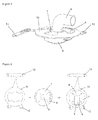
- Figure 3 demonstrates a sectional side view of a nasal respiratory mask system as an example of the present invention.
- Figure 4 demonstrates a perspective view of this nasal respiratory mask system.
- a mask cushion 4 (nasal mask cushion herein) is fixed on the face side of a first frame 6.
- a slide surface 7 is mounted on an opposite side to the face of the first frame 6.
- a shape of the slide surface 7 section of this first frame is roughly circular convex mirror shape with a hole at the center section, on which a roughly cylindrical connection section 15 to connect an elbow 9 with the first frame 6 is mounted.
- An inside of the first frame 6 is communicated with an inside of the elbow 9 via this connection section 15.
- a holding-down section 8 having a circular convex mirror shape and perforated at a central part is fixed on an intermediate section of such connection section 15.
- a second frame 10 is positioned between a slide surface 7 and a holding-down section 8 in the first frame and a slide surface 11 with a roughly circular convex mirror shape and perforated at the central part is mounted on the side of this second frame 10 facing the slide surface 7 of the first frame.
- the first frame 6 and the second frame 10 are connected in a ball-joint like form through this slide surface 11 and the slide surface 7 of the first frame.
- a holding-down section 8 of the first frame 6 prevents the first frame 6 from detaching the second frame 10.
- the second frame 10 is mounted with two connection sections 12 for a headgear strap positioned on the mouth side of a user and two connection sections 13 for a headgear strap positioned on the forehead side of a user.
- respiratory gas under positive pressure introduced from a hose for supplying respiratory gas under positive pressure passes through an elbow 9, a connection section 15, an inside of a first frame 6 and holes provided thereto (not shown) to reach an inside of a nasal mask cushion 4.
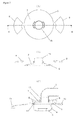
- Figure 5 demonstrates a perspective view of an example of a respiratory mask system in the present invention.
- This is basically similar to a nasal respiratory mask system according to Example 1 and providing a pair of holding-down sections 8 of a first frame in a fan-like form as well as providing a slit to match its shape on a slide surface 11 section of the second frame allows for single-piece molding of a first frame 6 and a connection section 15 with an elbow 9 and then assembling a second frame 10 with this piece.
- Figure 6 demonstrates a method to assemble such a respiratory mask system. After a holding-down section 8 of the first frame 6 is turned by 90 degrees against the second frame 10 to insert, the holding-down section 8 is turned by 90 degrees in an opposite direction to assemble.
- Figure 7 demonstrates a respiratory mask system as a modified example of Example 2.
- the present respiratory mask system has a structure, in which a pair of holding-down sections 8 in fan-like shape is detachably mounted on a connection section 15 of the first frame 6.
- Figure 7(A) herein is a plain view showing only the first frame 6 and the holding-down section 8
- Figure 7(B) is a sectional side view along a B-B-line in Figure 7(A)
- Figure 7(C) is a sectional side view to demonstrate an assembled state of a whole respiratory mask system.
- a method to assemble the present respiratory mask system is, by making the holding-down section 8 of the first frame as a separate part from other section of the first frame, it is engaged, after a connection section 15 in a first frame 6 and an elbow 9 fixed thereto are inserted into a hole at a center of a slide surface 11 of the second frame, with an engaging section mounted on a periphery of the connection section 15 completing assembling.
- Figure 8 demonstrates a sectional side view of an example of a respiratory mask system in the present invention.
- the present respiratory mask system is basically similar to the nasal respiratory mask system according to Example 1, but has a bearing 14 provided between a slide surface 7 of the first frame and a slide surface 11 of the second frame in order to improve slide motion.
- Bearing 14 herein is provided on the slide surface 7 side of the first frame.
- Figure 9 demonstrates a plain view of an example of a respiratory mask system in the present invention.
- the present respiratory mask system is basically similar to the nasal respiratory mask system according to Example 1, but is provided with four connection sections 12 for a headgear strap on the second frame 10 similar as connection sections 12 for a headgear strap on a mouth side as shown in Figure 3 , instead of mounting connection sections 13 for a headgear strap on a forehead side as shown in Figure 3 .
- the present invention provides a respiratory mask system used in CPAP therapy or NIPPV therapy.
Abstract
Description
- The present invention relates to a respiratory mask system used for continuous positive airway pressure (CPAP) therapy suitable for the treatment of sleep apnea syndrome, nasal intermittent positive pressure ventilation (NIPPV) therapy suitable for ventilatory insufficiency, and the like.
- One of the most effective therapeutic methods for sleep apnea syndrome is a continuous positive airway pressure (CPAP) method. While in this therapy a respiratory equipment is adopted for supplying positive pressure gas at about 400 to 2000 Pa to the nasal cavity, the nasal cavity and the mouth or the face of a user during sleep, in recent years devices with a function to control a pressure automatically responding to an occurrence state of apnea during therapy have also been used. A nasal intermittent positive pressure ventilation (NIPPV) method is used as one of the most effective therapeutic methods for ventilatory insufficiency, in which a respiratory equipment is adopted for supplying intermittent positive pressure gas at about 400 to 2400 Pa to the nasal cavity of a user. A mask for supplying positive pressure gas while applying pressure to the nasal cavity, a mask for supplying positive pressure gas while covering the nasal cavity and the mouth, and a mask for supplying positive pressure gas while covering the full face are called a nasal respiratory mask system, a full face mask, and a total face mask, respectively.
- A nasal respiratory mask system is described as an example in the following, but its content may be applied to a general respiratory mask system including a full face mask, a total full face mask and the like.
- A nasal respiratory mask system is, for example, as shown in
Figure 1 , generally provided with a hollownasal mask cushion 4 tightly sealing the face of a user, aframe 3 retaining thenasal mask cushion 4 at a predetermined position for supplying respiratory gas under positive pressure, aheadgear 16 connected with thisframe 3 andelastic headgear straps headgear 16 with theframe 3 in order to continuously supply positive pressure to the nasal cavity of a user (to both nose and mouth in case of a full face mask and to a full face in case of a total face mask). Such a nasal respiratory mask system then tightly seals the face of a user with thenasal mask cushion 4 by the tension ofheadgear straps 17 and 18 (see, for example,Patent Document 1,Patent Document 2 and Patent Document 3). - However, it is known that various factors cause slipping of the nasal mask cushion during wearing even if a nasal respiratory mask system is once worn properly. Accordingly, measures responding to each cause are taken to prevent or reduce its slip. For example, in a nasal respiratory mask system disclosed in
Patent Documents Patent Document 4, a flexible material is used in a wall around a connection section with a hose for supplying positive pressure gas in order to reduce slipping of a frame section pulled by the hose for positive pressure gas connected with the frame section. - Patent Document1: Japan Patent Laid-Open Publication No.
H11-000397 - Patent Document 2:
WO 01/097893 - Patent Document 3:
WO 98/04310 - Patent Document 4:
WO 96/17643 - However, it has been found that even if particular force is not applied from outside to a frame section and the like, for example, movement of user's head from side to side and up and down generates force to induce slipping of a nasal mask cushion section, resulting in its slipping state. Such slipping may not be eliminated immediately even after stopping head movement and often tends to stay without change.
- For instance, when a user tilts his face to a right direction while in bed, such slipping is caused by tendency of a nasal respiratory mask system equipped with a nasal mask cushion and a frame to fall by its own weight in a lower right direction. Further tension is thus applied to the left side of a strap to press the left side of the cushion to a face, thus conversely loosening the right side of the strap. As a result, excess force is applied to the left side of the cushion to press a face generating pain, creating in the right side a gap between the face and the cushion to cause abnormal gas leak.
- If such slip occurs but mild, a part of a contact surface of a nasal mask cushion with a face (for example, right side section) is stretched while the other part (for example, left side section) is shrunk, thus keeping a sort of a sealing state with a face. However, even if a sealing state is maintained, a user feels uncomfortable because of uneven pressure of a nasal mask cushion. That is, for example, when a user tilts his head to right in a state of being face up, a nasal respiratory mask system tends to slip to lower right by its own weight. A headgear to keep a frame at a predetermined position does not then move because of friction with a head, thereby applying tension to a left side strap and loosing a right side strap. This causes a tilt of a contact section of a mask cushion against a face, giving a user discomfort by uneven pressure of a nasal mask cushion.
- Stretching of a contact surface of a face with a nasal mask cushion may not absorb such slip any more when such slip is further increased, resulting in leak of respiratory gas under positive pressure from a contact surface.
- That is, an object of the present invention is to provide a nasal respiratory mask system capable of reducing or absorbing such lateral slip of a nasal mask cushion section unknown in the past. The present invention is effective to slipping by action of external force, but in particular, provides a nasal respiratory mask system with a mechanism to substantially prevent a mask cushion section from tilting to a face even if such slipping force is applied.
- The present invention is a nasal respiratory mask system contacting the face of a user for supplying respiratory gas under positive pressure to the user and provided with a mask cushion covering a nose, a nose and a mouth or a full face, a first frame connected with the above mask cushion and capable of supplying respiratory gas under positive pressure gas from a means for supplying respiratory gas under positive pressure, and a second frame connected with a headgear strap, in which the above mask cushion is disposed on a face side of the above first frame, the above first fame is disposed on a face side of the above second frame, a slide surface is formed on at least a side of the above first frame facing the above second frame and a side of the above second frame facing the above first frame, and the above first frame is connected slidably with the above second frame along the above slide surface.
- A nasal respiratory mask of the present invention herein is mounted with a headgear strap on a second frame and a user wears the nasal respiratory mask system on his head with this headgear strap and a headgear. Positive pressure gas from a means for supplying respiratory gas under positive pressure is supplied via an elbow and the like to a first frame, thus supplying positive pressure gas to a user.
- Such a basic principle of the present invention is described according to
Figure 2 . In a nasal respiratory mask system of the present invention, asecond frame 10 is fixed on thehead 1 of a user via a headgear strap similarly as aframe 3 in a conventional nasal respiratory mask system shown inFigure 1 . On the other hand, since afirst frame 6 is positioned closer to the face side than asecond frame 10 and amask cushion 4 is positioned further closer to the face side than thefirst frame 6, application of tension to a headgear strap enables themask cushion 4 to seal the face of a user. When thehead 1 of a user moves from side to side and up and down or external force is acted on the mask herein, thesecond frame 10 experiences force to be displaced relatively to thehead 1 of a user in the nasal respiratory mask system of the present invention. However, since thefirst frame 6 is connected slidably with thesecond frame 10 alongslide surfaces slide surfaces first frame 6 and thesecond frame 10. In particular, when theslide surfaces first frame 6 is connected with thesecond frame 10 in a ball-joint like form through theslide surfaces first frame 6 and thesecond frame 10 becomes smoother to further reduce or absorb the lateral slip. Furthermore, when the center of a spherical surface in theseslide surfaces head 1 of a user from side to side and up and down, tilting thehead 1 of a user from side to side and up and down does not tilt themask cushion 4 against the face of a user, thus keeping the pressure from the mask cushion to the face of a user to be uniform. - A nasal respiratory mask system of the present invention allows relative movement between a first frame and a second frame to reduce or absorb the lateral slip, even when force such as movement of the user's head and the like is applied in the direction to induce lateral slip of a mask cushion. Thus, by substantially preventing the mask cushion from tilting against a face, discomfort of a user is reduced and air tightness of the mask cushion to the face is maintained.
- A nasal respiratory mask system of the present invention, for example, may also use a resin for a first frame and a second frame to make it thin and solve problematic slip by such a simple mechanism, forming a lightweight nasal respiratory system.
-
-
Figure 1 is a schematic view of a conventional respiratory mask system. -
Figure 2 is a schematic vies of a respiratory mask system of the present invention. -
Figure 3 is a sectional side view of a nasal respiratory mask system in reference to Example 1 of the present invention. -
Figure 4 is a perspective view of a nasal respiratory mask system in reference to above Example 1. -
Figure 5 is a perspective view of a respiratory mask system in reference to Example 2 of the present invention. -
Figure 6 is a diagram to illustrate a method to assemble a respiratory mask system in reference to above Example 2. -
Figure 7 is a diagram to illustrate a method to assemble a respiratory mask system in reference to Example 3 of the present invention. -
Figure 8 is a sectional side view of a respiratory mask system in reference to Example 4 of the present invention. -
Figure 9 is a front view of a respiratory mask system in reference to Example 5 of the present invention. -
- 1. Head of user
- 2. Center of slide surface of mask cushion
- 3. Frame in conventional product
- 4. Mask cushion
- 5. Face contact section of mask cushion
- 6. First frame
- 7. Slide surface of first frame
- 8. Holding-down section of first frame
- 9. Elbow
- 10. Second frame
- 11. Slide surface of second frame
- 12. Connection section of headgear strap in second frame
- 13. Connection section of headgear strap in second frame
- 14. Bearing
- 15. Connection section with elbow
- 16. Headgear
- 17. Left headgear strap
- 18. Right headgear strap
- The present invention is next described in detail.
- As described above, the present invention is a respiratory mask system contacting the face of a user for supplying respiratory gas under positive pressure to the user and comprises a mask cushion covering a nose, a nose and a mouth or a full face, a first frame connected with the above mask cushion capable of supplying respiratory gas under positive pressure from a means for supplying respiratory gas under positive pressure, and a second frame connected with a headgear strap, in which the above mask cushion is disposed on a face side of the above first frame, the above first fame is disposed on a face side of the above second frame, a slide surface is formed on at least a side of the above first frame facing the above second frame or a side of the above second frame facing the above first frame, and the above first frame is connected slidably with the above second frame along the above slide surface.
- A means for supplying respiratory gas under positive pressure herein is a means to transport positive pressure gas supplied from a respiratory equipment to a respiratory mask system and generally transports respiratory gas under positive pressure to the respiratory mask system by connecting the respiratory equipment with the respiratory mask system using a flexible hose or by possibly using a rigid tube or by directly connecting the respiratory equipment with the respiratory mask system. Such a supply means may use other mechanism so far as the respiratory gas under positive pressure may be transported to a respiratory mask system.
- A mask cushion in a respiratory mask cushion of the present invention is a cushion to cover a nose, a nose and a mouth or a full face and formed in a hollow shape, that is, a roughly cylindrical shape for respiratory gas under positive pressure to pass. At least a contact section with a face in this mask cushion is constructed from an elastic body and, for example, in a nasal mask cushion, a structure or material capable of closely contacting a periphery of the nose of a user is used. Such construction allows absorbing individual difference in a facial shape of a user as well as preventing respiratory gas under positive pressure from leaking.
- Such a structure capable of good sealing is known and, for example, includes a double membrane structure according to
Patent Document 3 as a suitable example, but is not limited by this structure so far as seal is in a level not to allow leaking of respiratory gas under positive pressure in practical use. Materials for a face contact section of such a mask cushion include, for example, a silicone rubber. - For example, since air tightness of a respiratory gas under positive pressure in a nasal mask cushion is secured by pressing to a periphery of the nose of a user, a circumference of an open end at a user side is typically molded into substantially an isosceles triangular shape reflecting the nasal shape, for example, such as a structure according to
Patent Document 3. A shape of a whole nasal mask cushion is suitably made substantially isosceles triangular reflecting a shape of an open end in a user side, but may be in other shape so far as air tightness is assured. - Sections other than a face contact section of a mask cushion are not necessarily constructed from an elastic body. Their intermediate sections may further have, for example, a bellow structure according to
Patent Document 1. - A mask cushion may be molded in a single-piece, but may include a combination of a plurality of parts so far as leak of respiratory gas under positive pressure does not occur.
- A first frame in a respiratory mask system of the present invention comprises a connection with a mask cushion configured to enable supplying a respiratory gas under positive pressure from a means for supplying respiratory gas under positive pressure.
- Such a first frame typically has a mask cushion fixed to its face side and a connection section with an elbow in its opposite side as well as a convex slide surface formed in a spherical shape and protruding in a direction opposite to the face side. And the first frame is connected with a second frame in a ball-joint like form through the slide surface, and the first frame is further provided with a holding-down section with a shape to prevent disengagement from the second frame.
- As a typical example of such a first frame is specifically described, the first frame has, roughly speaking, a face on a face side and a face opposite to it. The mask cushion described above is fixed on the face side. On the other hand, a face on an opposite side to the face has a slide surface in a shape of a spherical surface and a holding-down section as well as a connection section with an elbow. "Fixing" of the mask cushion includes fixing by adhesion and fixing by a fixing member such as a clamp and the like, but also a case in which two or more parts among the first frame, mask cushion and elbow are molded in a single-piece. Conversely, the first frame is provided with the slide surface in a shape of a spherical surface and a holding-down section, and these sections may be molded in a single-piece, or manufactured separately and assembled later.
- In a respiratory mask system of the present invention, a slide surface may be formed on at least a side of a first frame facing a second frame or a side of the second frame facing the first frame, but a slide surface in a shape of the spherical surface is preferably formed on a face in an opposite side to a face side of the first frame as the typical example described above. A spherical surface herein refers to a shape, of which a part of a surface of a sphere is cut out. And such a spherical surface is in a convex form protruding in a direction opposite to the face side. More preferably, the spherical surface has a shape, of which a part of the surface of a sphere is cut through a plane, that is, preferably a shape of a circular convex mirror as viewed from the front side of a user. Such a shape makes relative movement between the first frame and the second frame smoother, enabling to further reduce or absorb problematic lateral slip.
- The center of a hypothetical sphere forming the spherical surface is preferably positioned above or near the center of revolving movement of the head of a user from side to side and up and down. The center of the revolving movement is generally positioned above or near the center of such a spherical form provided that the head of a user is assumed roughly spherical. Such a configuration prevents the mask cushion from tilting against the face of a user, even if the user wearing the mask tilts his head from side to side and up and down.
- A respiratory mask system of the present invention is used by connecting a means for supplying respiratory gas under positive pressure such as a hose and the like for supplying respiratory gas under positive pressure. Accordingly, a face of an opposite side to the face of a first frame is typically provided with a connection section with an elbow, which is a mounting section of a means for supplying respiratory gas under positive pressure. And the first frame has to be provided with a gas channel, through which respiratory gas under positive pressure introduced from a means for supplying respiratory gas under positive pressure may reach a mask cushion mounted on the first frame.
- A first frame in a respiratory mask system of the present invention also has a role of connecting a mask cushion and an elbow and may also have a holding-down section or slide surface so that a strong material within a limit required to realize such functions is used. It is generally constructed from plastics, for example, polycarbonate.
- As described above, a first frame in a respiratory mask system of the present invention is suitable to fix a mask cushion, capable of connecting a connection section of a means for supplying respiratory gas under positive pressure and capable of providing a holding-down section and a slide surface if needed and any one of structures may be used so far as the structure does not prevent relative displacement between the first frame and second frame.
- A second frame in a respiratory mask system of the present invention is connected with a headgear strap and has a role to fix the mask system together with this headgear strap and a headgear on the face of a user. Accordingly, the second frame is provided with a mounting section for a headgear strap or molded with a headgear section in a single-piece. Any one of these shapes may be used so far as the mask system of the present invention may be fixed on a face.
- As described above, in the respiratory mask system of the present invention, a slide surface is formed on at least a side of a first frame facing a second frame or a side of the second frame facing the first frame, and in particular, when the slide surface is provided on the face of an opposite side to a face side of the first frame, a slide surface corresponding to the slide surface of the first frame is preferably also provided on the face of a face side of the second frame. This gives a stable sliding state in relative displacement between the first frame and the second frame, enabling structurally good balance.
- Furthermore, preferably a slide surface of a second frame is formed in a shape of a spherical surface and in a convex shape protruding in the direction opposite, to a face side and the first frame is connected with the second frame in a ball-joint like form through this slide surface. More preferably, the spherical surface has a shape, of which a part of the surface of a sphere is cut through a plane, that is, preferably a shape of a circular concave mirror as viewed from the front side of a user. Such a shape makes relative movement between the first frame and the second frame smoother, enabling to further reduce or absorb problematic lateral slip.
- In particular, a center of this spherical surface as a slide surface is preferably positioned above or near a center of revolving movement of the head of a user from side to side and up and down. In this case, a mask cushion does not tilt against the face of a user, even if the user tilts his head from side to side and up and down and pressure from the mask cushion on the face of a user is kept uniformly.
- A first frame and a second frame not only must contact through the spherical slid surfaces each frame has, but also enable relative movement through the slide surface. A range of such movement may be in a level to dissolve the problematic slip. A specific numerical value depends on each shape of respiratory mask systems in the present invention, but those skilled in the art may easily determine a range to satisfy the movement after simple trials.
- In a case of a construction, of which a second frame is positioned between a first frame and a holding-down section, a section having the slide surface as a part of such a second frame is preferably in a shape to concave a flat plate in a spherical shape. This section is sandwiched between a slide surface of the first frame and the holding-down section to prevent the first frame from coming off from the second frame. The reason for providing the holding-down section on the first frame is that, when tension is applied to a headgear strap or pressure of respiratory gas under positive pressure is applied, force is exerted in a direction to press a slide surface of the first frame on a slide surface of the second frame, but provision of the holding-down section on the first frame is required to prevent both from detaching, even if this is not the case.
- A part of a holding-down section of the first section contacting the second frame is preferably in a roughly spherical shape corresponding to a shape of the face opposite to a slide surface of such a second frame. A shape of the face opposite to a slide surface of the second frame or a holding-down section of the first frame section contacting the second frame may have other shape so far as it does not prevent relative movement between the first frame and the second frame along the slide surface but prevents the first frame from detaching the second frame.
- A second frame has a role to fix a respiratory mask system on the face of a user and uses a strong material within a limit required thereto. It is generally constructed from plastics, for instance, polycarbonate.
- An elbow is connected with a first frame to mount a means for supplying respiratory gas under positive pressure such as a hose and the like for supplying respiratory gas under positive pressure. A structure of such an elbow may use a known mechanism so far as it has a structure to prevent respiratory gas under positive pressure from leaking at a connection section with a hose and the like. Such an elbow is preferably rotatably connected with a first frame. In the description of the present specification, it is expressed as "elbow" for convenience, but so-called "L-shaped" is not required so far as a means for supplying respiratory gas under positive pressure may be mounted, a channel for respiratory gas under positive pressure may be secured in its inside and it has a structure not preventing relative movement between the first frame and the second frame through the slide surface described above. However, an L-shape shown in Examples is preferred under consideration of easy handling after mounting a hose and the like for supplying respiratory gas under positive pressure. A means for supplying respiratory gas under positive pressure such as a hose and the like for supplying respiratory gas under positive pressure, in the first place, may also be directly mounted on the first frame without using the elbow.
- In a nasal respiratory mask system of the present invention, a mask cushion is positioned on a face side of a first frame and the first frame is positioned on a face side of a second frame. Furthermore, a slide surface of the first frame, a slide surface of the second frame facing it, other sections of the second frame, a headgear strap connected with it, an elbow and a holding-down section of the first frame are preferably disposed in the face opposite to the face side of the first frame. Each section and each member have to be further positioned not interfering slide movement, since the slide surface of the first frame and the slide surface of the second frame have to be allowed to slide movement in a certain range.
- A connection section of the first frame with the elbow may be mounted on a different site from the slide surface of the first frame, but preferably provided with a hole on the slide surface of the first frame. In particular, the shape of the slide surface of the first frame is preferably a circular convex mirror shape as viewed from a front side of a user, and in this case, the connection section with the elbow is particularly preferred to fix at its center. In either case a through-hole is preferably provided at least on a site facing the contact section in the second frame in order not to prevent movement of the second frame including a headgear and a strap connected thereto. For example, when a connection section with an elbow is fixed on a center of the slide surface of the first frame with a circular convex mirror shape, a hole is necessarily formed also on the slide surface of the second frame. That is, the slide surface of the second frame becomes a doughnut shape. A size of the hole has to be not only in a range through which a section to fix the connection section with the elbow passes freely, but also not preventing the slide movement described above.
- Further, a second frame is preferably constructed with a holding-down section in a first frame section to prevent disengagement. Such a holding-down section provided may be positioned at a location to hold down any section of the second frame so far as its objective is achieved, but preferably has a structure to hold down a slide surface section of the second frame. For example, a structure to hold down from a periphery of the slide surface section of the second frame may be used, but when a connection section with an elbow is mounted on a center of the slide surface in the first frame with a circular convex mirror shape as described above, a holding-down section is preferably mounted so as to extend outwards from a fixing section of an elbow in the connection section. A nasal respiratory mask system of the present invention shown in
Figure 3 is one of such examples. A holding-down section of the first frame inFigure 3 is in a doughnut shape, but may be in a plurality of nail-shaped members so far as its objective is achieved. The same is true in case to hold down the second frame from periphery. - A structure shown in
Figure 3 is a preferred one, but at the same time may have such problems as difficulty in single-piece molding of a first frame, an elbow and a holding-down section and assembling parts after molding. Since a holding-down section of the first frame may have a shape to hold down only a part of the slide surface in the second frame, so far as preventing the first frame from detaching the second frame, a shape of a holding-down section of the first frame matches with a deleted section of a slide surface in the second frame as shown inFigure 5 to enable inserting the second frame into the first frame, which is molded with the elbow in a single-piece. - An example of a preferred embodiment includes one further having a bearing on a slide surface between the first frame and the second frame. This is added to improve sliding. Such a bearing may be mounted on any side of the sliding surfaces. Additionally, a self-lubricating resin may be used or a lubricant such as grease and the like may be applied in order to improve slide movement.
- Specific examples of the present invention are further described in detail in reference with drawings as follows.
-
Figure 3 demonstrates a sectional side view of a nasal respiratory mask system as an example of the present invention.Figure 4 demonstrates a perspective view of this nasal respiratory mask system. A mask cushion 4 (nasal mask cushion herein) is fixed on the face side of afirst frame 6. On the other hand, aslide surface 7 is mounted on an opposite side to the face of thefirst frame 6. A shape of theslide surface 7 section of this first frame is roughly circular convex mirror shape with a hole at the center section, on which a roughlycylindrical connection section 15 to connect anelbow 9 with thefirst frame 6 is mounted. An inside of thefirst frame 6 is communicated with an inside of theelbow 9 via thisconnection section 15. A holding-downsection 8 having a circular convex mirror shape and perforated at a central part is fixed on an intermediate section ofsuch connection section 15. - A
second frame 10 is positioned between aslide surface 7 and a holding-downsection 8 in the first frame and aslide surface 11 with a roughly circular convex mirror shape and perforated at the central part is mounted on the side of thissecond frame 10 facing theslide surface 7 of the first frame. Thefirst frame 6 and thesecond frame 10 are connected in a ball-joint like form through thisslide surface 11 and theslide surface 7 of the first frame. A holding-downsection 8 of thefirst frame 6 prevents thefirst frame 6 from detaching thesecond frame 10. Thesecond frame 10 is mounted with twoconnection sections 12 for a headgear strap positioned on the mouth side of a user and twoconnection sections 13 for a headgear strap positioned on the forehead side of a user. - In such a nasal respiratory mask system, respiratory gas under positive pressure introduced from a hose for supplying respiratory gas under positive pressure passes through an
elbow 9, aconnection section 15, an inside of afirst frame 6 and holes provided thereto (not shown) to reach an inside of anasal mask cushion 4. -
Figure 5 demonstrates a perspective view of an example of a respiratory mask system in the present invention. This is basically similar to a nasal respiratory mask system according to Example 1 and providing a pair of holding-downsections 8 of a first frame in a fan-like form as well as providing a slit to match its shape on aslide surface 11 section of the second frame allows for single-piece molding of afirst frame 6 and aconnection section 15 with anelbow 9 and then assembling asecond frame 10 with this piece. -
Figure 6 demonstrates a method to assemble such a respiratory mask system. After a holding-downsection 8 of thefirst frame 6 is turned by 90 degrees against thesecond frame 10 to insert, the holding-downsection 8 is turned by 90 degrees in an opposite direction to assemble. -
Figure 7 demonstrates a respiratory mask system as a modified example of Example 2. The present respiratory mask system has a structure, in which a pair of holding-downsections 8 in fan-like shape is detachably mounted on aconnection section 15 of thefirst frame 6.Figure 7(A) herein is a plain view showing only thefirst frame 6 and the holding-downsection 8,Figure 7(B) is a sectional side view along a B-B-line inFigure 7(A) and Figure 7(C) is a sectional side view to demonstrate an assembled state of a whole respiratory mask system. A method to assemble the present respiratory mask system is, by making the holding-downsection 8 of the first frame as a separate part from other section of the first frame, it is engaged, after aconnection section 15 in afirst frame 6 and anelbow 9 fixed thereto are inserted into a hole at a center of aslide surface 11 of the second frame, with an engaging section mounted on a periphery of theconnection section 15 completing assembling. -
Figure 8 demonstrates a sectional side view of an example of a respiratory mask system in the present invention. The present respiratory mask system is basically similar to the nasal respiratory mask system according to Example 1, but has abearing 14 provided between aslide surface 7 of the first frame and aslide surface 11 of the second frame in order to improve slide motion.Bearing 14 herein is provided on theslide surface 7 side of the first frame. -
Figure 9 demonstrates a plain view of an example of a respiratory mask system in the present invention. The present respiratory mask system is basically similar to the nasal respiratory mask system according to Example 1, but is provided with fourconnection sections 12 for a headgear strap on thesecond frame 10 similar asconnection sections 12 for a headgear strap on a mouth side as shown inFigure 3 , instead of mountingconnection sections 13 for a headgear strap on a forehead side as shown inFigure 3 . - The present invention provides a respiratory mask system used in CPAP therapy or NIPPV therapy.
Claims (7)
- A respiratory mask system, contacting the face of a user for supplying respiratory gas under positive pressure to the user, comprising:a mask cushion covering a nose, a nose and a mouth or a full face;a first fame connected with the mask cushion enabling to supply respiratory gas under positive pressure from a means for supplying respiratory gas under positive pressure; and a second frame connected with a headgear strap,the mask cushion being disposed on the face side of the first frame and the first frame being disposed on the face side of the second frame,a slide surface being formed at least in a side of the first frame facing the second frame or in a side of the second frame facing the first frame, andthe first frame being connected slidably with the second frame along the slide surface.
- The respiratory mask system according to claim 1, wherein the slide surface is formed in a shape of a spherical surface and in a convex shape protruding in the direction opposite to a face side, and
the first frame is connected with the second frame in a ball-joint like form through the slide surface. - The respiratory mask system according to claim 2, wherein a center of the spherical surface as the slide surface is disposed above or near a center of revolving movement of a user's head from side to side and up and down.
- The respiratory mask system according to in any of claims 1 to 3, wherein a holding-down section is provided to prevent detachment of connection between the first frame and the second frame.
- The respiratory mask system according to in any of claims 1 to 4, wherein a connection section with an elbow as a mounting section of a means for supplying respiratory gas under positive pressure is provided in a position corresponding to a center of the slide surface in the first frame and a through-hole is provided at least at a site facing the connection section in the second frame.
- The respiratory mask system according to any of claims 1 to 5, wherein a pair of slide surfaces is correspondingly formed in the side of the first frame facing the second frame and in the side of the second frame facing the first frame.
- The respiratory mask system according to claim 6, wherein a bearing is further provided on at least a slide surface of the first frame or a slide surface of the second surface.
Applications Claiming Priority (2)
| Application Number | Priority Date | Filing Date | Title |
|---|---|---|---|
| JP2006298674 | 2006-11-02 | ||
| PCT/JP2007/070356 WO2008053715A1 (en) | 2006-11-02 | 2007-10-18 | Breathing mask system |
Publications (3)
| Publication Number | Publication Date |
|---|---|
| EP2078534A1 true EP2078534A1 (en) | 2009-07-15 |
| EP2078534A4 EP2078534A4 (en) | 2014-03-12 |
| EP2078534B1 EP2078534B1 (en) | 2015-09-02 |
Family
ID=39344058
Family Applications (1)
| Application Number | Title | Priority Date | Filing Date |
|---|---|---|---|
| EP07830090.2A Active EP2078534B1 (en) | 2006-11-02 | 2007-10-18 | Breathing mask system |
Country Status (12)
| Country | Link |
|---|---|
| US (1) | US8881731B2 (en) |
| EP (1) | EP2078534B1 (en) |
| JP (1) | JP4734421B2 (en) |
| KR (1) | KR20090079931A (en) |
| CN (1) | CN101534888B (en) |
| AU (1) | AU2007315576B2 (en) |
| CA (1) | CA2667889A1 (en) |
| ES (1) | ES2553164T3 (en) |
| HK (2) | HK1132945A1 (en) |
| MY (1) | MY150937A (en) |
| TW (1) | TWI478739B (en) |
| WO (1) | WO2008053715A1 (en) |
Cited By (2)
| Publication number | Priority date | Publication date | Assignee | Title |
|---|---|---|---|---|
| EP2327441A1 (en) * | 2009-11-25 | 2011-06-01 | Dräger Medical GmbH | System for ventilating patients |
| EP3300759A4 (en) * | 2015-06-23 | 2018-06-06 | BMC Medical Co., Ltd. | Face mask assembly |
Families Citing this family (9)
| Publication number | Priority date | Publication date | Assignee | Title |
|---|---|---|---|---|
| DE202009018972U1 (en) | 2008-03-04 | 2014-12-09 | Resmed Limited | mask system |
| US11331447B2 (en) | 2008-03-04 | 2022-05-17 | ResMed Pty Ltd | Mask system with snap-fit shroud |
| WO2010148453A1 (en) * | 2009-06-24 | 2010-12-29 | Resmed Ltd | Adjustable mask system and related methods |
| US9539403B2 (en) * | 2009-08-26 | 2017-01-10 | Resmed Limited | Mask system |
| US9199054B2 (en) * | 2012-04-23 | 2015-12-01 | Sleepnet Corporation | Articulating headgear connector for respiratory masks |
| TWI494143B (en) * | 2013-05-27 | 2015-08-01 | Hsiner Co Ltd | Breathing mask |
| EP3808397B1 (en) * | 2014-03-18 | 2024-04-24 | Fisher & Paykel Healthcare Limited | Gel resuscitation mask |
| CN108543184A (en) * | 2018-03-09 | 2018-09-18 | 绩溪县上庄老胡开文墨厂 | It is a kind of to be used to grind the mask worn when ink powder |
| CN114177467B (en) * | 2021-12-01 | 2023-06-27 | 郑州大学第一附属医院 | Breathing machine |
Citations (1)
| Publication number | Priority date | Publication date | Assignee | Title |
|---|---|---|---|---|
| US5662101A (en) * | 1995-12-07 | 1997-09-02 | Respironics, Inc. | Respiratory facial mask |
Family Cites Families (14)
| Publication number | Priority date | Publication date | Assignee | Title |
|---|---|---|---|---|
| JP2590514B2 (en) | 1987-03-13 | 1997-03-12 | 日本電装株式会社 | Blower fan |
| JPS641397A (en) * | 1987-06-24 | 1989-01-05 | Mitsubishi Electric Corp | Outdoor microphone equipment |
| US5458139A (en) * | 1993-08-30 | 1995-10-17 | Susan O. Pearl | Low profile tracheostomy tube assembly |
| AUPM997394A0 (en) | 1994-12-09 | 1995-01-12 | University Of Sydney, The | Gas delivery mask |
| CN2218574Y (en) * | 1995-01-19 | 1996-01-31 | 寻国杰 | Artificial respirator |
| US5572994A (en) * | 1995-06-07 | 1996-11-12 | Smith; Steven W. | Occlusion resistant oxygen supply conduit for a nasal cannula |
| AUPO126596A0 (en) | 1996-07-26 | 1996-08-22 | Resmed Limited | A nasal mask and mask cushion therefor |
| US5921239A (en) * | 1997-01-07 | 1999-07-13 | Sunrise Medical Hhg Inc. | Face mask for patient breathing |
| JP4290773B2 (en) | 1997-06-11 | 2009-07-08 | 帝人株式会社 | Breathing nose mask |
| US6338342B1 (en) * | 1999-02-22 | 2002-01-15 | Cabot Safety Intermediate Corporation | Respirator headpiece and release mechanism |
| US6497232B2 (en) | 1999-02-22 | 2002-12-24 | Cabot Safety Intermediate Corporation | Respirator headpiece and release mechanism |
| US6986352B2 (en) | 2000-06-22 | 2006-01-17 | Resmed Limited | Mask with gusset |
| US6758215B2 (en) * | 2002-10-17 | 2004-07-06 | Paul G. Begum | Aromatic travel mask |
| US7513255B2 (en) * | 2005-06-03 | 2009-04-07 | Ric Investments, Llc | Patient interface device with universal headgear mounting member |
-
2007
- 2007-10-18 KR KR1020097009610A patent/KR20090079931A/en active IP Right Grant
- 2007-10-18 AU AU2007315576A patent/AU2007315576B2/en not_active Ceased
- 2007-10-18 WO PCT/JP2007/070356 patent/WO2008053715A1/en active Application Filing
- 2007-10-18 US US12/513,349 patent/US8881731B2/en active Active
- 2007-10-18 MY MYPI20091572 patent/MY150937A/en unknown
- 2007-10-18 JP JP2008542041A patent/JP4734421B2/en active Active
- 2007-10-18 ES ES07830090.2T patent/ES2553164T3/en active Active
- 2007-10-18 CN CN2007800407891A patent/CN101534888B/en active Active
- 2007-10-18 CA CA002667889A patent/CA2667889A1/en not_active Abandoned
- 2007-10-18 EP EP07830090.2A patent/EP2078534B1/en active Active
- 2007-10-22 TW TW096139483A patent/TWI478739B/en not_active IP Right Cessation
-
2009
- 2009-12-01 HK HK09111255.8A patent/HK1132945A1/en not_active IP Right Cessation
- 2009-12-07 HK HK09111430.6A patent/HK1133403A1/en not_active IP Right Cessation
Patent Citations (1)
| Publication number | Priority date | Publication date | Assignee | Title |
|---|---|---|---|---|
| US5662101A (en) * | 1995-12-07 | 1997-09-02 | Respironics, Inc. | Respiratory facial mask |
Non-Patent Citations (1)
| Title |
|---|
| See also references of WO2008053715A1 * |
Cited By (3)
| Publication number | Priority date | Publication date | Assignee | Title |
|---|---|---|---|---|
| EP2327441A1 (en) * | 2009-11-25 | 2011-06-01 | Dräger Medical GmbH | System for ventilating patients |
| EP3300759A4 (en) * | 2015-06-23 | 2018-06-06 | BMC Medical Co., Ltd. | Face mask assembly |
| US11273277B2 (en) | 2015-06-23 | 2022-03-15 | Bmc Medical Co., Ltd. | Face mask assembly |
Also Published As
| Publication number | Publication date |
|---|---|
| WO2008053715A1 (en) | 2008-05-08 |
| AU2007315576A1 (en) | 2008-05-08 |
| US8881731B2 (en) | 2014-11-11 |
| MY150937A (en) | 2014-03-14 |
| HK1133403A1 (en) | 2010-03-26 |
| JPWO2008053715A1 (en) | 2010-02-25 |
| EP2078534B1 (en) | 2015-09-02 |
| JP4734421B2 (en) | 2011-07-27 |
| TW200836782A (en) | 2008-09-16 |
| CN101534888B (en) | 2011-11-16 |
| CA2667889A1 (en) | 2008-05-08 |
| HK1132945A1 (en) | 2010-03-12 |
| US20100012128A1 (en) | 2010-01-21 |
| CN101534888A (en) | 2009-09-16 |
| TWI478739B (en) | 2015-04-01 |
| KR20090079931A (en) | 2009-07-22 |
| AU2007315576B2 (en) | 2012-05-03 |
| ES2553164T3 (en) | 2015-12-04 |
| EP2078534A4 (en) | 2014-03-12 |
Similar Documents
| Publication | Publication Date | Title |
|---|---|---|
| US8881731B2 (en) | Respiratory mask system | |
| EP2747819B1 (en) | Patient interface with snap-fit connector | |
| US9867958B2 (en) | Auto-adjusting membrane for respiratory interface device | |
| JP6270478B2 (en) | Patient interface device with self-adjusting cushion | |
| JP5047159B2 (en) | Double buffer subject interface device | |
| AU2005332069B2 (en) | Cheek-mounted patient interface | |
| US20140311496A1 (en) | Patient interface having headgear post for clip or strap | |
| US20140261435A1 (en) | Cushion for patient interface with localized region of reduced stiffness | |
| US11160943B2 (en) | Cushion for breathing mask and breathing mask | |
| US20110232647A1 (en) | Respiratory interface with flexing faceplate | |
| JP6868664B2 (en) | Patient interface with adaptive system, respiratory mask and pad for the adaptive system | |
| JP2013536701A (en) | Patient interface device with frame assembly having dual Y support structure | |
| US20160015922A1 (en) | Lower mount flexing oral-nasal mask | |
| KR20090029829A (en) | Respiring nose mask system | |
| WO2016203338A1 (en) | Passive nose bridge pressure distributing insert | |
| US9387301B2 (en) | Pad assembly having outer casing and support element | |
| RU2574574C2 (en) | Breathing apparatus | |
| WO2011080605A1 (en) | Pad assembly having outer casing and support element |
Legal Events
| Date | Code | Title | Description |
|---|---|---|---|
| PUAI | Public reference made under article 153(3) epc to a published international application that has entered the european phase |
Free format text: ORIGINAL CODE: 0009012 |
|
| 17P | Request for examination filed |
Effective date: 20090505 |
|
| AK | Designated contracting states |
Kind code of ref document: A1 Designated state(s): AT BE BG CH CY CZ DE DK EE ES FI FR GB GR HU IE IS IT LI LT LU LV MC MT NL PL PT RO SE SI SK TR |
|
| REG | Reference to a national code |
Ref country code: HK Ref legal event code: DE Ref document number: 1133403 Country of ref document: HK |
|
| DAX | Request for extension of the european patent (deleted) | ||
| A4 | Supplementary search report drawn up and despatched |
Effective date: 20140212 |
|
| RIC1 | Information provided on ipc code assigned before grant |
Ipc: A61M 16/06 20060101AFI20140206BHEP |
|
| 17Q | First examination report despatched |
Effective date: 20140224 |
|
| GRAP | Despatch of communication of intention to grant a patent |
Free format text: ORIGINAL CODE: EPIDOSNIGR1 |
|
| INTG | Intention to grant announced |
Effective date: 20150427 |
|
| GRAS | Grant fee paid |
Free format text: ORIGINAL CODE: EPIDOSNIGR3 |
|
| GRAA | (expected) grant |
Free format text: ORIGINAL CODE: 0009210 |
|
| AK | Designated contracting states |
Kind code of ref document: B1 Designated state(s): AT BE BG CH CY CZ DE DK EE ES FI FR GB GR HU IE IS IT LI LT LU LV MC MT NL PL PT RO SE SI SK TR |
|
| REG | Reference to a national code |
Ref country code: GB Ref legal event code: FG4D |
|
| REG | Reference to a national code |
Ref country code: AT Ref legal event code: REF Ref document number: 746145 Country of ref document: AT Kind code of ref document: T Effective date: 20150915 Ref country code: CH Ref legal event code: EP |
|
| REG | Reference to a national code |
Ref country code: IE Ref legal event code: FG4D |
|
| REG | Reference to a national code |
Ref country code: DE Ref legal event code: R096 Ref document number: 602007042928 Country of ref document: DE |
|
| REG | Reference to a national code |
Ref country code: FR Ref legal event code: PLFP Year of fee payment: 9 |
|
| REG | Reference to a national code |
Ref country code: ES Ref legal event code: FG2A Ref document number: 2553164 Country of ref document: ES Kind code of ref document: T3 Effective date: 20151204 |
|
| REG | Reference to a national code |
Ref country code: AT Ref legal event code: MK05 Ref document number: 746145 Country of ref document: AT Kind code of ref document: T Effective date: 20150902 |
|
| PG25 | Lapsed in a contracting state [announced via postgrant information from national office to epo] |
Ref country code: GR Free format text: LAPSE BECAUSE OF FAILURE TO SUBMIT A TRANSLATION OF THE DESCRIPTION OR TO PAY THE FEE WITHIN THE PRESCRIBED TIME-LIMIT Effective date: 20151203 Ref country code: LV Free format text: LAPSE BECAUSE OF FAILURE TO SUBMIT A TRANSLATION OF THE DESCRIPTION OR TO PAY THE FEE WITHIN THE PRESCRIBED TIME-LIMIT Effective date: 20150902 Ref country code: FI Free format text: LAPSE BECAUSE OF FAILURE TO SUBMIT A TRANSLATION OF THE DESCRIPTION OR TO PAY THE FEE WITHIN THE PRESCRIBED TIME-LIMIT Effective date: 20150902 Ref country code: LT Free format text: LAPSE BECAUSE OF FAILURE TO SUBMIT A TRANSLATION OF THE DESCRIPTION OR TO PAY THE FEE WITHIN THE PRESCRIBED TIME-LIMIT Effective date: 20150902 |
|
| REG | Reference to a national code |
Ref country code: HK Ref legal event code: GR Ref document number: 1133403 Country of ref document: HK |
|
| REG | Reference to a national code |
Ref country code: LT Ref legal event code: MG4D Ref country code: NL Ref legal event code: MP Effective date: 20150902 |
|
| PG25 | Lapsed in a contracting state [announced via postgrant information from national office to epo] |
Ref country code: AT Free format text: LAPSE BECAUSE OF FAILURE TO SUBMIT A TRANSLATION OF THE DESCRIPTION OR TO PAY THE FEE WITHIN THE PRESCRIBED TIME-LIMIT Effective date: 20150902 Ref country code: SE Free format text: LAPSE BECAUSE OF FAILURE TO SUBMIT A TRANSLATION OF THE DESCRIPTION OR TO PAY THE FEE WITHIN THE PRESCRIBED TIME-LIMIT Effective date: 20150902 Ref country code: PL Free format text: LAPSE BECAUSE OF FAILURE TO SUBMIT A TRANSLATION OF THE DESCRIPTION OR TO PAY THE FEE WITHIN THE PRESCRIBED TIME-LIMIT Effective date: 20150902 |
|
| PG25 | Lapsed in a contracting state [announced via postgrant information from national office to epo] |
Ref country code: IS Free format text: LAPSE BECAUSE OF FAILURE TO SUBMIT A TRANSLATION OF THE DESCRIPTION OR TO PAY THE FEE WITHIN THE PRESCRIBED TIME-LIMIT Effective date: 20160102 Ref country code: CZ Free format text: LAPSE BECAUSE OF FAILURE TO SUBMIT A TRANSLATION OF THE DESCRIPTION OR TO PAY THE FEE WITHIN THE PRESCRIBED TIME-LIMIT Effective date: 20150902 Ref country code: EE Free format text: LAPSE BECAUSE OF FAILURE TO SUBMIT A TRANSLATION OF THE DESCRIPTION OR TO PAY THE FEE WITHIN THE PRESCRIBED TIME-LIMIT Effective date: 20150902 Ref country code: NL Free format text: LAPSE BECAUSE OF FAILURE TO SUBMIT A TRANSLATION OF THE DESCRIPTION OR TO PAY THE FEE WITHIN THE PRESCRIBED TIME-LIMIT Effective date: 20150902 Ref country code: SK Free format text: LAPSE BECAUSE OF FAILURE TO SUBMIT A TRANSLATION OF THE DESCRIPTION OR TO PAY THE FEE WITHIN THE PRESCRIBED TIME-LIMIT Effective date: 20150902 |
|
| PG25 | Lapsed in a contracting state [announced via postgrant information from national office to epo] |
Ref country code: PT Free format text: LAPSE BECAUSE OF FAILURE TO SUBMIT A TRANSLATION OF THE DESCRIPTION OR TO PAY THE FEE WITHIN THE PRESCRIBED TIME-LIMIT Effective date: 20160104 Ref country code: RO Free format text: LAPSE BECAUSE OF FAILURE TO SUBMIT A TRANSLATION OF THE DESCRIPTION OR TO PAY THE FEE WITHIN THE PRESCRIBED TIME-LIMIT Effective date: 20150902 |
|
| REG | Reference to a national code |
Ref country code: CH Ref legal event code: PL |
|
| REG | Reference to a national code |
Ref country code: DE Ref legal event code: R097 Ref document number: 602007042928 Country of ref document: DE |
|
| PG25 | Lapsed in a contracting state [announced via postgrant information from national office to epo] |
Ref country code: MC Free format text: LAPSE BECAUSE OF FAILURE TO SUBMIT A TRANSLATION OF THE DESCRIPTION OR TO PAY THE FEE WITHIN THE PRESCRIBED TIME-LIMIT Effective date: 20150902 |
|
| PLBE | No opposition filed within time limit |
Free format text: ORIGINAL CODE: 0009261 |
|
| STAA | Information on the status of an ep patent application or granted ep patent |
Free format text: STATUS: NO OPPOSITION FILED WITHIN TIME LIMIT |
|
| REG | Reference to a national code |
Ref country code: IE Ref legal event code: MM4A |
|
| PG25 | Lapsed in a contracting state [announced via postgrant information from national office to epo] |
Ref country code: LI Free format text: LAPSE BECAUSE OF NON-PAYMENT OF DUE FEES Effective date: 20151031 Ref country code: CH Free format text: LAPSE BECAUSE OF NON-PAYMENT OF DUE FEES Effective date: 20151031 |
|
| 26N | No opposition filed |
Effective date: 20160603 |
|
| PG25 | Lapsed in a contracting state [announced via postgrant information from national office to epo] |
Ref country code: SI Free format text: LAPSE BECAUSE OF FAILURE TO SUBMIT A TRANSLATION OF THE DESCRIPTION OR TO PAY THE FEE WITHIN THE PRESCRIBED TIME-LIMIT Effective date: 20150902 Ref country code: DK Free format text: LAPSE BECAUSE OF FAILURE TO SUBMIT A TRANSLATION OF THE DESCRIPTION OR TO PAY THE FEE WITHIN THE PRESCRIBED TIME-LIMIT Effective date: 20150902 |
|
| REG | Reference to a national code |
Ref country code: FR Ref legal event code: PLFP Year of fee payment: 10 |
|
| PG25 | Lapsed in a contracting state [announced via postgrant information from national office to epo] |
Ref country code: IE Free format text: LAPSE BECAUSE OF NON-PAYMENT OF DUE FEES Effective date: 20151018 |
|
| PG25 | Lapsed in a contracting state [announced via postgrant information from national office to epo] |
Ref country code: BE Free format text: LAPSE BECAUSE OF FAILURE TO SUBMIT A TRANSLATION OF THE DESCRIPTION OR TO PAY THE FEE WITHIN THE PRESCRIBED TIME-LIMIT Effective date: 20150902 |
|
| REG | Reference to a national code |
Ref country code: DE Ref legal event code: R082 Ref document number: 602007042928 Country of ref document: DE Representative=s name: HOFFMANN - EITLE PATENT- UND RECHTSANWAELTE PA, DE Ref country code: DE Ref legal event code: R081 Ref document number: 602007042928 Country of ref document: DE Owner name: TEIJIN LTD., OSAKA-SHI, JP Free format text: FORMER OWNER: TEIJIN PHARMA LIMITED, TOKYO, JP |
|
| PG25 | Lapsed in a contracting state [announced via postgrant information from national office to epo] |
Ref country code: HU Free format text: LAPSE BECAUSE OF FAILURE TO SUBMIT A TRANSLATION OF THE DESCRIPTION OR TO PAY THE FEE WITHIN THE PRESCRIBED TIME-LIMIT; INVALID AB INITIO Effective date: 20071018 Ref country code: BG Free format text: LAPSE BECAUSE OF FAILURE TO SUBMIT A TRANSLATION OF THE DESCRIPTION OR TO PAY THE FEE WITHIN THE PRESCRIBED TIME-LIMIT Effective date: 20150902 |
|
| REG | Reference to a national code |
Ref country code: GB Ref legal event code: 732E Free format text: REGISTERED BETWEEN 20170511 AND 20170517 |
|
| PG25 | Lapsed in a contracting state [announced via postgrant information from national office to epo] |
Ref country code: CY Free format text: LAPSE BECAUSE OF FAILURE TO SUBMIT A TRANSLATION OF THE DESCRIPTION OR TO PAY THE FEE WITHIN THE PRESCRIBED TIME-LIMIT Effective date: 20150902 |
|
| PG25 | Lapsed in a contracting state [announced via postgrant information from national office to epo] |
Ref country code: MT Free format text: LAPSE BECAUSE OF FAILURE TO SUBMIT A TRANSLATION OF THE DESCRIPTION OR TO PAY THE FEE WITHIN THE PRESCRIBED TIME-LIMIT Effective date: 20150902 Ref country code: TR Free format text: LAPSE BECAUSE OF FAILURE TO SUBMIT A TRANSLATION OF THE DESCRIPTION OR TO PAY THE FEE WITHIN THE PRESCRIBED TIME-LIMIT Effective date: 20150902 |
|
| REG | Reference to a national code |
Ref country code: FR Ref legal event code: TP Owner name: TEIJIN LIMITED, JP Effective date: 20170912 |
|
| REG | Reference to a national code |
Ref country code: FR Ref legal event code: PLFP Year of fee payment: 11 |
|
| PG25 | Lapsed in a contracting state [announced via postgrant information from national office to epo] |
Ref country code: LU Free format text: LAPSE BECAUSE OF NON-PAYMENT OF DUE FEES Effective date: 20151018 |
|
| REG | Reference to a national code |
Ref country code: ES Ref legal event code: PC2A Owner name: TEIJIN LIMITED Effective date: 20180112 |
|
| REG | Reference to a national code |
Ref country code: FR Ref legal event code: PLFP Year of fee payment: 12 |
|
| PGFP | Annual fee paid to national office [announced via postgrant information from national office to epo] |
Ref country code: FR Payment date: 20181025 Year of fee payment: 12 Ref country code: IT Payment date: 20181025 Year of fee payment: 12 Ref country code: ES Payment date: 20181108 Year of fee payment: 12 Ref country code: GB Payment date: 20181025 Year of fee payment: 12 |
|
| GBPC | Gb: european patent ceased through non-payment of renewal fee |
Effective date: 20191018 |
|
| PG25 | Lapsed in a contracting state [announced via postgrant information from national office to epo] |
Ref country code: IT Free format text: LAPSE BECAUSE OF NON-PAYMENT OF DUE FEES Effective date: 20191018 Ref country code: FR Free format text: LAPSE BECAUSE OF NON-PAYMENT OF DUE FEES Effective date: 20191031 Ref country code: GB Free format text: LAPSE BECAUSE OF NON-PAYMENT OF DUE FEES Effective date: 20191018 |
|
| PG25 | Lapsed in a contracting state [announced via postgrant information from national office to epo] |
Ref country code: ES Free format text: LAPSE BECAUSE OF NON-PAYMENT OF DUE FEES Effective date: 20191019 |
|
| PGFP | Annual fee paid to national office [announced via postgrant information from national office to epo] |
Ref country code: DE Payment date: 20220620 Year of fee payment: 16 |