EP2080263B1 - Vibration-type actuator - Google Patents
Vibration-type actuator Download PDFInfo
- Publication number
- EP2080263B1 EP2080263B1 EP07830228.8A EP07830228A EP2080263B1 EP 2080263 B1 EP2080263 B1 EP 2080263B1 EP 07830228 A EP07830228 A EP 07830228A EP 2080263 B1 EP2080263 B1 EP 2080263B1
- Authority
- EP
- European Patent Office
- Prior art keywords
- axis
- vibration
- contact
- portions
- contact surface
- Prior art date
- Legal status (The legal status is an assumption and is not a legal conclusion. Google has not performed a legal analysis and makes no representation as to the accuracy of the status listed.)
- Not-in-force
Links
- 238000006073 displacement reaction Methods 0.000 claims description 31
- 230000033001 locomotion Effects 0.000 claims description 16
- 230000008602 contraction Effects 0.000 claims description 10
- 238000005452 bending Methods 0.000 claims description 7
- 238000010276 construction Methods 0.000 description 10
- 230000000694 effects Effects 0.000 description 4
- 239000000919 ceramic Substances 0.000 description 3
- 230000000750 progressive effect Effects 0.000 description 3
- 239000007787 solid Substances 0.000 description 3
- 241000287509 Piciformes Species 0.000 description 2
- 239000000853 adhesive Substances 0.000 description 2
- 230000001070 adhesive effect Effects 0.000 description 2
- 238000006243 chemical reaction Methods 0.000 description 2
- 230000007423 decrease Effects 0.000 description 2
- 238000000034 method Methods 0.000 description 2
- 230000007935 neutral effect Effects 0.000 description 2
- 230000001133 acceleration Effects 0.000 description 1
- 238000004026 adhesive bonding Methods 0.000 description 1
- 230000003247 decreasing effect Effects 0.000 description 1
- 230000005284 excitation Effects 0.000 description 1
- 239000002783 friction material Substances 0.000 description 1
- 229910010272 inorganic material Inorganic materials 0.000 description 1
- 239000011147 inorganic material Substances 0.000 description 1
- 238000004519 manufacturing process Methods 0.000 description 1
- 239000000463 material Substances 0.000 description 1
- 238000003825 pressing Methods 0.000 description 1
- 230000001629 suppression Effects 0.000 description 1
- 238000003466 welding Methods 0.000 description 1
Images


Classifications
-
- H—ELECTRICITY
- H02—GENERATION; CONVERSION OR DISTRIBUTION OF ELECTRIC POWER
- H02N—ELECTRIC MACHINES NOT OTHERWISE PROVIDED FOR
- H02N2/00—Electric machines in general using piezoelectric effect, electrostriction or magnetostriction
- H02N2/0005—Electric machines in general using piezoelectric effect, electrostriction or magnetostriction producing non-specific motion; Details common to machines covered by H02N2/02 - H02N2/16
- H02N2/005—Mechanical details, e.g. housings
- H02N2/0065—Friction interface
-
- H—ELECTRICITY
- H02—GENERATION; CONVERSION OR DISTRIBUTION OF ELECTRIC POWER
- H02N—ELECTRIC MACHINES NOT OTHERWISE PROVIDED FOR
- H02N2/00—Electric machines in general using piezoelectric effect, electrostriction or magnetostriction
- H02N2/0005—Electric machines in general using piezoelectric effect, electrostriction or magnetostriction producing non-specific motion; Details common to machines covered by H02N2/02 - H02N2/16
- H02N2/001—Driving devices, e.g. vibrators
- H02N2/0015—Driving devices, e.g. vibrators using only bending modes
-
- H—ELECTRICITY
- H02—GENERATION; CONVERSION OR DISTRIBUTION OF ELECTRIC POWER
- H02N—ELECTRIC MACHINES NOT OTHERWISE PROVIDED FOR
- H02N2/00—Electric machines in general using piezoelectric effect, electrostriction or magnetostriction
- H02N2/0005—Electric machines in general using piezoelectric effect, electrostriction or magnetostriction producing non-specific motion; Details common to machines covered by H02N2/02 - H02N2/16
- H02N2/001—Driving devices, e.g. vibrators
- H02N2/002—Driving devices, e.g. vibrators using only longitudinal or radial modes
-
- H—ELECTRICITY
- H02—GENERATION; CONVERSION OR DISTRIBUTION OF ELECTRIC POWER
- H02N—ELECTRIC MACHINES NOT OTHERWISE PROVIDED FOR
- H02N2/00—Electric machines in general using piezoelectric effect, electrostriction or magnetostriction
- H02N2/02—Electric machines in general using piezoelectric effect, electrostriction or magnetostriction producing linear motion, e.g. actuators; Linear positioners ; Linear motors
- H02N2/026—Electric machines in general using piezoelectric effect, electrostriction or magnetostriction producing linear motion, e.g. actuators; Linear positioners ; Linear motors by pressing one or more vibrators against the driven body
-
- H—ELECTRICITY
- H02—GENERATION; CONVERSION OR DISTRIBUTION OF ELECTRIC POWER
- H02N—ELECTRIC MACHINES NOT OTHERWISE PROVIDED FOR
- H02N2/00—Electric machines in general using piezoelectric effect, electrostriction or magnetostriction
- H02N2/10—Electric machines in general using piezoelectric effect, electrostriction or magnetostriction producing rotary motion, e.g. rotary motors
- H02N2/16—Electric machines in general using piezoelectric effect, electrostriction or magnetostriction producing rotary motion, e.g. rotary motors using travelling waves, i.e. Rayleigh surface waves
- H02N2/163—Motors with ring stator
Definitions
- the present invention relates to a vibration-type actuator, such as an ultrasonic motor, for generating vibrations in an elastic body and utilizing the resultant vibrational energy to generate a driving force.
- a vibration-type actuator such as an ultrasonic motor
- FIG. 17 is a perspective view showing the appearance of a linear-type ultrasonic motor.
- the linear-type ultrasonic motor 510 is comprised of a vibrator 501 and a linear slider 506.
- the vibrator 501 includes a piezoelectric element 505 formed into a rectangular thin plate, and a vibrating body 502 integrally joined to one surface of the piezoelectric element 505.
- the vibrating body 502 has a rectangular-shaped base and two protruding portions 503-1, 503-2 projecting from an upper surface of the base.
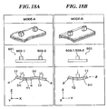
- FIGS. 18A and 18B are views showing the forms of two vibration modes (MODE-A and MODE-B) excited in the vibrator of FIG. 17 .
- Each of the two vibration modes is a bending vibration mode excited in the out-of-plane direction of the plate-shaped vibrator 501.
- the vibrator 501 is designed such as to resonate in these modes at frequencies approximately equal to each other.
- FIG. 18A Two lower parts of FIG. 18A show the vibrator 501 as seen from the Y direction.
- the MODE-A vibration is excited in the vibrator 501, there are formed three vibration nodes ⁇ as shown in the lowest part of FIG. 18A (a second-order bending vibration mode).
- Each vibration node extends in the Y direction of the vibrator 501
- the rectangular column-shaped contact members 503-1, 503-2 are disposed in the vicinity of the nodes formed by the MODE-A vibration.
- the MODE-A vibration causes contact surfaces 504-1, 504-2 of the contact members 503-1, 503-2 to reciprocally move in the X direction, as shown by an arrow.
- FIG. 18B Two lower parts of FIG. 18B show the vibrator 501 as seen from the X direction.
- the MODE-B vibration is excited in the vibrator 501, two vibration nodes ⁇ are formed (a first-order bending vibration mode), as shown in the lowest part of FIG. 18B .
- Each vibration node extends in the X direction of the vibrator 501.
- the nodes generated in the MODE-A vibration and the nodes generated in the MODE-B vibration extend perpendicular to each other in the XY plane.
- the contact members 503-1, 503-2 are disposed in the vicinity of the antinode formed by the MODE-B vibration.
- the MODE-B vibration causes a reciprocal motion of the contact surfaces 504-1, 504-2 in the Z direction.
- the above-described vibration modes are excited in the vibrator 501 by an inverse piezoelectric effect caused when a desired AC signal is input to the piezoelectric element 505.
- the excitation is such that a phase difference between the MODE-A vibration and the MODE-B vibration is nearly equal to +n/2 or -n/2
- near elliptic motions of the contact surfaces 504-1, 504-2 are generated in the XZ plane in FIG. 17 .
- a relative displacement motion occurs between the vibrator 501 and the linear slider 506 disposed in pressure contact with the contact surfaces 504-1, 504-2.
- Positive and negative signs (+), (-) in FIG. 18A each represent the direction of an X directional component of distortion observed when the vibrator 501 is deformed by the vibration (Ditto in FIG. 18B ).
- the positive sign (+) represents that the piezoelectric element 505 is elongated in the X direction
- the negative sign (-) represents that the piezoelectric element 505 is contracted in the X direction.
- each half of the piezoelectric element 505 is divided into two regions in the thickness direction in terms of the direction of distortion. At the boundary between the two regions, there is a plane where the X directional distortion is not produced, which is referred to as the neutral plane T1. It is also understood that the sign (distortion direction) is reversed between both halves of the piezoelectric element 505 with respect to the X-direction center portion thereof ( FIG. 18A ).
- the piezoelectric element 505 is divided into two regions in the thickness direction thereof in terms of the signs (+), (-) each representing the direction of the Y directional distortion of the piezoelectric element 505 ( FIG. 18B ).
- the boundary between the two regions is referred to as the neutral plane T2.
- both the linear slider 506 and the two contact members 503-1, 503-2 provided integrally with the vibrating body 502 are each made of an inorganic material that has no spring function in its structure, and therefore, smooth contact cannot be achieved.
- the present inventors designed a contact member 609 having a spring function, which is shown in FIG. 19 .
- the contact member 609 is comprised of a protruding portion 603, two fixing portions 607 that support the protruding portion 603, and spring portions 608.
- the protruding portion 603 is required to be formed into a protrusion having a contact surface 604 thereof disposed in contact with a linear slider (not shown), which is driven in the X direction in FIG. 19 . Therefore, the protruding portion 603 includes shoulder portions 613 respectively extending from two long side edges of the contact surface 604 of a rectangular shape.
- the two fixing portions 607 are disposed in a direction parallel to the moving direction of the linear slider at a distance therefrom.
- the vibration body 602 is formed with a groove 612 having a sufficient depth such that the spring portions 608, horizontally extending from the fixing portions 607, can each have a spring function.
- the signs (+), (-) respectively represent the elongation and contraction of the piezoelectric element in the X direction in the MODE-A of FIG. 18A .
- the two fixing portions 607 of the contact member 609 are moved toward and away from each other in the X direction.
- FIGS. 20A to 20C are views, as seen from the Y direction in FIG. 19 , showing how the contact member 609 is deformed when the fixing portions 607 in FIG. 19 are elongated and contracted in the in-plane direction.
- FIG. 20A shows a shape of the contact member 609 observed when no vibration is generated in the vibrator 601
- FIG. 20B shows a shape of the contact member 609 observed when the fixing portions 607 are moved away from each other
- FIG. 20C show a shape of the contact member 609 observed when the fixing portions 607 are moved toward each other.
- Larger arrows each represent the direction of displacement of the contact surface 604. Due to deformation of the shoulder portions 613, the contact surface 604 is displaced in the Z direction (the vertical direction in FIGS. 20A to 20C ) in synchronization with movements of the fixing portions 607. At the moment when the displacement of FIG.
- the contact member 609 disposed thereat is deformed as shown in FIG. 20B .
- the contact member 609 disposed thereat is deformed as shown in FIG. 20C . Accordingly, in the arrangement where the two contact members 609 are used instead of the contact members 503-1, 503-2 of the vibrator of FIGS. 18A and 18B , the contact members 609 are displaced in the Z direction in antiphase with each other.
- the contact surface 604 makes a reciprocal motion that results from the combination of the displacement in the X direction and the displacement in the Z direction.
- a trajectory of FIG. 21B is obtained in the above described arrangement, which is different from a trajectory in the prior art example shown in FIG. 21A .
- two projections are displaced in the Z direction in antiphase with each other. Therefore, if the trajectory of the contact surface 604 of one of the two contact members 609 is as shown in FIG. 21B , then the trajectory of another contact surface 604 becomes as shown in FIG. 21C .
- US 5 233 258 discloses an ultrasonic sheet feeder including a convex shell, piezoelectric ceramic elements, a base, a roller, and a driving power source.
- the convex shell has a protruding middle portion.
- Each piezoelectric ceramic element has one end in contact with a corresponding one of the two ends of the convex shell.
- the base serves to fix the other end of each of the piezoelectric ceramic elements.
- the roller is arranged to oppose the protruding middle portion of the convex shell so as to urge a paper sheet against the convex shell when the paper sheet is loaded.
- US 2004/0251782 discloses an electromechanical motor having a driving element comprising two electromechanical vibrators. The two electromechanical vibrators are interconnected by a link member.
- the electromechanical vibrators are, at the ends connected to the link, attached to a backbone of a stator by a respective resilient joint member. A mechanical connection to the backbone is thus introduced essentially between the vibrator and the link. A vibration of one of the electromechanical vibrators is transferred into a tilting or torsion of one of the joint members, and a similar vibration of the other electromechanical vibrator provides a tilting or torsion of the other joint member.
- US 2004/251782 discloses an electromechanical motor having a driving element comprising two electromechanical vibrators which are interconnected by a link member.
- the electromechanical vibrators are, at the ends connected to the link, attached to a backbone of a stator by a respective resilient joint member. A mechanical connection to the backbone is thus introduced essentially between the vibrator and the link.
- a vibration of one of the electromechanical vibrators is transferred into a tilting or torsion of one of the joint members, and a similar vibration of the other electromechanical vibrator provides a tilting or torsion of the other joint member.
- the link, interconnecting the vibrators is subsequently caused to deform and move.
- an actuating portion of the link can be brought along a motion path and this can in turn be used to interact with a body to be moved.
- FIG. 1 is a view showing, for explanation of a contact member of a vibration-type actuator according to an exemplary embodiment of this invention, a structure formed by functional parts of the contact member.
- the contact member 9 is comprised of a protruding portion 3, fixing portions 7, and converting portions 11.
- the protruding portion 3 has a surface thereof formed with a contact surface 4 that is urged against a driven body for contact therewith.
- the fixing portions 7 are coupled to a base (a vibrating body 102, described later) that is deformed to drive the contact member 9, and are provided in plural in number so as to support the protruding portion 3 from opposite directions.
- the converting portions 11 are each disposed between the protruding portion 3 and the fixing portion 7 concerned.
- the fixing portions 7 When deformation such as bending vibration or longitudinal vibration is generated in the base, the fixing portions 7 are moved toward and away from each other in the in-plane direction. At that time, a change occurs in the relative distance between the fixing portions 7 in synchronization with the vibration.
- the converting portions 11 convert an amount of change in the relative distance into a contact surface displacement ⁇ .
- a first form is to provide the converting portions 11 for suppression of an undesired amplitude of the contact surface 4, which can be caused by the vibration of the base used for driving the contact member 9.
- a second form is to provide the converting portions 11 at such positions where an undesired amplitude of the contact surface is suppressed to thereby attain much larger amplitude of the contact surface.
- the first form is described in a first embodiment, and the second form is described in a second embodiment. Furthermore, third and fourth embodiments are described as exemplary application forms of the second embodiment.
- FIG. 2A is a perspective view of a vibration-type actuator according to the first embodiment of this invention
- FIG. 2B is a perspective view of a contact member of the vibration-type actuator.
- the actuator of this embodiment has a construction having novel contact members 109-1, 109-2 that replace the two contact members 609 disposed in the vicinity of nodes of the MODE-A vibration generated in the above described prior art linear ultrasonic motor.
- the contact members 109-1, 109-2 are separate members from the vibrating body 102 which is the base, and are fixed to the vibrating body 102 after being formed into a shape shown in FIG. 2B .
- the contact members 109-1, 109-2 are each comprised of a protruding portion 103, two fixing portions 107 that support the protruding portion 103, and converting portions 111.
- the protruding portion 103 is required to be formed into a protrusion having a contact surface 104 thereof adapted to be in contact with a linear slider 106 which is driven in the X direction in FIG. 2A , and therefore, includes shoulder portions 113 respectively extending in the height direction (the Z direction) from two long side edges of the contact surface of a rectangular shape via rounded portions.
- the two fixing portions 107 are disposed at a distance from the linear slider (not shown) in a direction parallel to the moving direction (the X direction) of the linear slider.
- Each converting portion 111 is disposed between the shoulder portion 113 and the fixing portion 107 concerned.
- Each converting portion 111 extends obliquely relative to the contact surface 104, and extends away from the contact surface 104 toward the side opposite from the contact surface 104 in the height direction (the Z direction).
- the vibrating body 102 of the vibrator 101 is formed with a groove 112 having a sufficient depth such that each converting portion 111 has a spring function.
- the vibrating body 102 can be formed with raised projections at its positions where the fixing portions 107 are mounted, or the fixing portions can be formed to project toward the vibrating body 102. In that case, the groove 112 can be eliminated.
- the contact members 109-1, 109-2 are formed by pressing a rectangular plate, and therefore, the fixing portions 107, the converting portions 111, and the protruding portion 103 are formed integrally with one another.
- the contact members are made of a stainless material which is excellent in stamping performance, and are formed to be substantially uniform in thickness between the fixing portions 107 which are fixed by welding or adhesive bonding to the vibrating body 102 as a base.
- the construction of this embodiment is attained by replacing the prior art contact members 503-1, 503-2, or 609 by the novel contact members 109-1, 109-2.
- the contact members 109-1, 109-2 disposed in the vicinity of nodes of MODE-A vibration are affected by the X-direction distortion components shown in FIG. 18A , and the distance between the fixing portions in each of the contact members 109-1, 109-2 increases and decreases in the in-plane direction.
- the converting portions 111 are so configured as to extend obliquely relative to the fixing portions 107 in a direction (the negative Z direction) opposite from the projecting direction of the protruding portion 103.
- a behavior to the elongation and contraction in the in-plane direction is similar to that of FIGS. 20A to 20C , but the converting portions 111 show a behavior opposite to that of the protruding portion 103.
- the converting portions 111 move the contact surface 104 upward in the Z direction when the fixing portions 107 are moved away from each other, and move the contact surface 104 downward in the Z direction when the fixing portions 107 are moved toward each other.
- the converting portions 111 convert the elongation/contraction deformation of the fixing portions 107 in the X direction (more generally, a first axis direction) into the reciprocal motion of the contact surface 104 in the Z direction (more generally, a second axis direction).
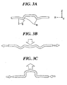
- FIGS. 3A to 3C are views showing states of deformation of the contact member of FIGS. 2A and 2B as seen from the Y direction in the coordinate system of FIGS. 2A and 2B .
- FIG. 3A shows a shape of the contact members 109-1, 109-2 observed when no vibration is generated in the vibrator 101
- FIG. 3B shows a shape of the contact members observed when the fixing portions 107 are moved away from each other
- FIG. 3C shows a shape of the contact members observed when the fixing portions are moved toward each other. Larger arrows each represent the direction of deformation of the contact surface 104. The following is a comparison with FIGS. 20A to 20C each showing a deformation of the contact member 609 that does not have the converting portions 111.
- the direction of deformation of the contact surface 104 observed when the fixing portions 107 are moved away from each other coincides with the direction of deformation of the contact surface 604 observed when the fixing portions 607 are moved away from each other, both of which are a downward direction relative to the paper plane of FIGS. 3B and 20B .
- the direction of deformation of the contact surface 104 observed when the fixing portions 107 are moved toward each other coincides with the direction of deformation of the contact surface 604 observed when the fixing portions 607 are moved toward each other, both of which are an upward direction relative to the paper plane of FIGS. 3C and 20C .
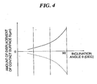
- FIG. 4 is a view showing a relation between inclination angle ⁇ of the converting portions and Z-axis direction displacement ⁇ of the contact surface observed when the fixing portions of the contact member of FIG. 2B are moved by a distance of 1 ⁇ m toward and away from each other, as shown respectively by a solid curve and a dotted curve.
- the inclination angle ⁇ is an angle formed between the inclined surface of the converting portion 111 and the vertical direction (Z axis direction), with the contact surface 104 extending horizontally.
- the inclination angle of the converting portion 111 which is taken along the abscissa in FIG. 4 , is equal to 90 degrees, the fixing portion 107 and the converting portion 111 are in the same plane as with the case of the contact member of FIG. 19 in which no converting portions 111 are provided.
- the elliptic trajectory of the vibrator 101 is improved from that of FIGS. 21B and 21C to that of FIG. 21A .
- the mounting positions of the contact members 109 can be shifted in the X axis direction.
- the amount of displacement of the contact surface 104 in the out-of-plane direction caused by the elongation and contraction of the fixing portions 107 in the in-plane direction can be adjusted by changing the length and thickness of the converting portions 111, etc.
- the curves shown in FIG. 4 represent an exemplary tendency observed in a given condition determined as a function of the length and thickness of the converting portions, etc. It has been found that similar effects can be achieved even if inclined parts of the converting portions 111 are each formed into a rolled/curved surface other than a flat surface.
- the above described first embodiment shows an example where the converting portions 111 are provided to suppress an undesired amplitude of the contact surface 104.
- a second embodiment there is described a construction in which the converting portions can be disposed at such positions where an undesired amplitude of the contact surface is suppressed and much larger amplitude of the contact surface can be attained.
- vibration modes are excited which are the same as the two vibration modes (MODE-A and MODE-B) of FIGS. 18A and 18B .
- FIG. 5A is a view showing a relation in MODE-A between X coordinate value on a vibrating body of the second embodiment and X-axis direction amplitude of a surface of the vibrating body
- FIG. 5B is a view showing a relation between X coordinate value and Z-axis direction amplitude.
- the prior art protruding portions 503-1, 503-2 are disposed in the vicinity of the node positions in FIG. 5B so as not to generate in the MODE-A an undesired displacement ⁇ of the contact surface in the Z axis direction.
- the X-direction vibration has its maximum amplitude in opposite end portion regions in which the absolute X coordinate value is larger than that at the node positions in FIG. 5B . Since an undesired Z-direction amplitude is also generated in the end portion regions, these regions have not been used heretofore.
- the second embodiment uses contact members one of which is shown in FIG. 6 , making it possible to dispose the contact surfaces in the end portion regions.
- FIG. 6 is a perspective view showing the contact member of the vibrating body according to the second embodiment of this invention.
- the contact member 209 is a plate-like article which is comprised of fixing portions 207 and converting portions 211 and to which a protruding portion 203 is fixedly mounted.
- the construction is the same as that of FIGS. 2A and 2B , and therefore, an explanation thereof is omitted.
- the shoulder portions 113 are provided to form the protruding portion 103, and the contact surface 104 is displaced in the Z direction when the two fixing portions 107 are moved toward and away from each other in the in-plane direction.
- a lower portion of the protruding portion 203, below the contact surface is changed from a hollow structure to a solid structure so that the protruding portion 203 can be regarded as a rigid body.
- the contact surface of the protruding portion 203 is not displaced in the Z direction when the fixing portions 207 are elongated and contracted in the in-plane direction. For this reason, as for the direction of deformation observed when the contact member 209 is elongated and contracted in the in-plane direction, it is enough to only consider a behavior of the converting portions 211.
- FIGS. 8A to 8C are views in which the deformation of the contact member of FIG. 6 is seen from the Y direction of a coordinate system shown in FIG. 6 .
- FIG. 8A shows a shape of the contact member 209 observed when no vibration is generated in the vibrator
- FIG. 8B shows a shape of the contact member observed when the fixing portions 207 are moved away from each other
- FIG. 8C shows a shape of the contact member observed when the fixing portions 207 are moved toward each other. Larger arrows show the direction of deformation of the contact surface 204.
- the converting portions 211 When the fixing portions 207 are moved away from each other, the converting portions 211 cause the contact surface 204 to move upward in the Z direction (i.e., to move in the positive Z direction). When the fixing portions 207 are moved toward each other, the converting portions 211 cause the contact surface 204 to move downward in the Z direction (i.e., to move in the negative Z direction) .
- the direction in which the contact surface 204 of this embodiment is deformed by the motions of the fixing portions 207 is opposite from that observed in the cases of FIGS. 3A to 3C and FIGS. 20A to 20C .
- This indicates that at the position X X1 the surface is contracted in the X direction.
- the fixing portions 207 of the contact member 209 are moved toward each other, and the contact surface 204 is displaced in the negative Z direction as shown in FIG. 8C .
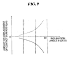
- FIG. 9 is a view showing a relation between inclination angle ⁇ of the converting portions and Z-axis-direction displacement ⁇ of the contact surface observed when the fixing portions of the contact member in FIG. 6 are moved by a distance of 1 ⁇ m toward and away from each other as shown respectively by a solid curve and a dotted curve.
- the inclination angle ⁇ is an angle formed between the inclined surface of the converting portion 211 and the vertical direction (the Z axis direction), with the contact surface 204 extending horizontally.
- the inclination angle of the converting portion 211 which is taken along the abscissa in FIG. 9 , is equal to 90 degrees, the fixing portion 207 and the converting portion 211 are in the same plane as with the case of the contact member of FIG. 19 in which no converting portions 211 are provided.
- the amount of displacement of the contact surface 204 in the out-of-plane direction caused by the elongation and contraction of the fixing portions 207 in the in-plane direction can be adjusted by changing the length and thickness of the converting portions 211, etc.
- the curves shown in FIG. 9 represent an exemplary tendency observed in a given condition determined as a function of the length and thickness of the converting portions, etc.
- the protruding portion 3 can have a shape that can substantially be regarded as a rigid body.
- the plate thickness of the shoulder portion which forms a side wall of the protruding portion 203 of the contact member 209 shown in FIG. 2B , can be sufficiently thickened so as to prevent the deformation of the protruding portion 203 due to the elongation and contraction of the fixing portions 207 in the X direction.
- the protruding portion 203 can be regarded as a rigid body, and therefore, intended effects can be attained.
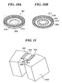
- FIGS. 10A and 10B are upper and lower perspective views each showing a vibrating body of the third embodiment.
- a vibrator 301 of the ring-type ultrasonic motor is comprised of an annular elastic body 315 and a piezoelectric element 305.
- a comb-like protrusion group 316 is formed on one axial side of the elastic body 315.
- a friction material 317 is adhesive bonded to an upper surface of the protrusion group 316.
- An annular piezoelectric element 305 as an electro-mechanical energy conversion element is adhesive bonded to another axial side of the elastic body 315, which is formed with a patterned electrode 318.
- the patterned electrode 318 is equally divided into electrode parts, the number of which is equal to four times as large as the degree of a vibration mode excited in the annular portion of the vibrator 301.
- the electrode parts are sequentially supplied with a sinusoidal AC voltage with a 90-degree time phase difference.
- the piezoelectric element 305 When supplied with an AC voltage of a frequency near the natural frequency of a vibration mode to be excited, the piezoelectric element 305 is elongated and contracted, and the elastic body 315 resonates because of a bending moment applied thereto. Vibrations (modes) excited by the AC voltage with the 90-degree time phase difference are the same in shape but different in phase from one another, and a combined vibration generates a progressive vibration wave (progressive wave).
- FIG. 11 is a perspective view showing an example where contact members are mounted to the ring-type ultrasonic motor.
- each contact member 309 As shown in FIG. 11 , two fixing portions 307 of each contact member 309 are respectively mounted on adjacent protrusions of the protrusion group 316, and a contact surface 304 of the contact member 309 is disposed near the center between the adjacent protrusions.
- the vibrator 301 (see FIGS. 10A and 10B ) includes contact members 309 the number of which is the same as the number of protrusions of the comb-like protrusion group 316. These contact members 309 are circumferentially arranged on the entire circumference of the vibrator 301.
- the contact members 309 has the same construction as that of the contact member 209 shown in FIG. 6 .
- the contact members 309 there are used a plurality of the contact members 309 each having one contact surface 304.
- a ring-shaped contact member can be used in order to reduce costs and simplify a fabrication process.
- the number of the protrusions is the same as that of the contact members 309 in this embodiment, this is not limitative since it is sometimes advantageous to make the number of the protrusions not equal to the number of the contact members depending on the way of arrangement of the contact surfaces 304.
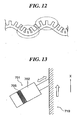
- FIG. 12 is a fragmentary view showing a relation between driving vibration and the protrusion group as seen from the contour of the ring-shaped vibrating body shown in FIGS. 10A and 10B .
- a plurality of protrusions are included in the length of one wavelength of the progressive wave.
- a relative circumferential distance between adjacent protrusions changes depending on the positional relation between protrusions and wave crests/troughs.
- Protrusion tip ends are made to be spaced from each other at wave crests, as shown at a right-side part of FIG. 12 surrounded by dotted-chain line, and made close to each other at wave troughs, as shown at a left-side part of FIG. 12 surrounded by dotted-chain line.
- the change in circumferential distance produces effects which are the same or similar to those produced by the X-direction elongation and contraction in the above described first and second embodiments.
- the distance between adjacent protrusion is made larger at positions near crest peaks, and therefore, the contact member 9 is deformed as shown in FIG. 8B , whereby the axis-direction amplitude can be increased. Since the distance between protrusions of the ring-shaped vibrator 301 is sufficiently large, the converting portions of the contact member 309 can be made large in length. As a result, the degree of conversion of the change in inter-fixing-portion distance into the displacement of the contact surface can be set to be large.
- the contact surfaces 304 can each have an elliptic trajectory with the increased axial amplitude. Furthermore, using the contact members 309, the contact surfaces 304 on the vibrator 301 side can each have a spring function, whereby stable driving can be achieved.
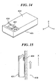
- FIG. 13 is a view showing the construction of a woodpecker-type actuator mounted with the contact member of FIG. 6 .
- a piezoelectric element 705 held by a vibrator 701 is repeatedly elongated and contracted in the axis direction.
- a tip end portion of the vibrator 701 strikes a surface of a driven body 719, as a woodpecker does.
- a frictional driving force is conveyed to the driven body 719, and the driven body 719 is driven in the direction shown by an arrow in FIG. 13 .
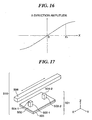
- FIG. 14 is a perspective view of a vibrating body according to the fourth embodiment.
- a piezoelectric element 405 is fixedly attached to one surface of the vibrating body 402 formed into a quadratic prism-shape, and a contact member 409 is disposed on another surface of the vibrating body 402 on the side remote from the piezoelectric element 405.
- FIG. 15 is a view showing a positional relation between the vibrating body 402 of FIG. 14 and a driven body 419.
- the driven body 419 is disposed in parallel to a vibrator 401 so as to be in light contact therewith.
- the vibrator 401 is excited at a frequency near the resonance frequency of a first-order longitudinal wave, for example.
- a node of the first-order longitudinal wave is formed at a position near the axial center of the vibrator 401, and opposite end portions of the vibrator 401 are displaced in opposite directions.
- FIG. 16 is a view for explaining an amount of displacement between the vibrating body of FIG. 14 and the driven body.
- the contact surface 404 makes a reciprocal motion in the direction shown by an arrow in FIG. 15 , and conveys a driving force to the surface of the driven body 419 as a woodpecker does, to thereby drive the driven body 419.
- the vibrator 401 of this embodiment can be disposed parallel to the contact surface of the driven body, thereby making it possible greatly reduce a space occupied by the vibrator 401. Furthermore, by using the contact member 409 of this embodiment, the contact surface 404 on the vibrator 401 side can have a spring function, whereby smooth contact can be attained and stable driving can be realized.
Description
- The present invention relates to a vibration-type actuator, such as an ultrasonic motor, for generating vibrations in an elastic body and utilizing the resultant vibrational energy to generate a driving force.
- Heretofore, various proposals have been made for an ultrasonic motor of a type linearly driving a driven element. Such an ultrasonic motor is disclosed, for example, in Japanese Laid-open Patent Publication No.
2004-304887 FIGS. 17 ,18A, and 18B . -
FIG. 17 is a perspective view showing the appearance of a linear-type ultrasonic motor. - As shown in
FIG. 17 , the linear-typeultrasonic motor 510 is comprised of avibrator 501 and alinear slider 506. Thevibrator 501 includes apiezoelectric element 505 formed into a rectangular thin plate, and a vibratingbody 502 integrally joined to one surface of thepiezoelectric element 505. The vibratingbody 502 has a rectangular-shaped base and two protruding portions 503-1, 503-2 projecting from an upper surface of the base. -
FIGS. 18A and 18B are views showing the forms of two vibration modes (MODE-A and MODE-B) excited in the vibrator ofFIG. 17 . - Each of the two vibration modes is a bending vibration mode excited in the out-of-plane direction of the plate-
shaped vibrator 501. Thevibrator 501 is designed such as to resonate in these modes at frequencies approximately equal to each other. - Two lower parts of
FIG. 18A show thevibrator 501 as seen from the Y direction. When the MODE-A vibration is excited in thevibrator 501, there are formed three vibration nodes α as shown in the lowest part ofFIG. 18A (a second-order bending vibration mode). Each vibration node extends in the Y direction of thevibrator 501 - As shown in
FIG. 18A , the rectangular column-shaped contact members 503-1, 503-2 are disposed in the vicinity of the nodes formed by the MODE-A vibration. The MODE-A vibration causes contact surfaces 504-1, 504-2 of the contact members 503-1, 503-2 to reciprocally move in the X direction, as shown by an arrow. - Two lower parts of
FIG. 18B show thevibrator 501 as seen from the X direction. When the MODE-B vibration is excited in thevibrator 501, two vibration nodes β are formed (a first-order bending vibration mode), as shown in the lowest part ofFIG. 18B . Each vibration node extends in the X direction of thevibrator 501. Thus, the nodes generated in the MODE-A vibration and the nodes generated in the MODE-B vibration extend perpendicular to each other in the XY plane. - As shown in
FIG. 18B , the contact members 503-1, 503-2 are disposed in the vicinity of the antinode formed by the MODE-B vibration. The MODE-B vibration causes a reciprocal motion of the contact surfaces 504-1, 504-2 in the Z direction. - The above-described vibration modes are excited in the
vibrator 501 by an inverse piezoelectric effect caused when a desired AC signal is input to thepiezoelectric element 505. When the excitation is such that a phase difference between the MODE-A vibration and the MODE-B vibration is nearly equal to +n/2 or -n/2, near elliptic motions of the contact surfaces 504-1, 504-2 are generated in the XZ plane inFIG. 17 . By virtue of the elliptic motions, a relative displacement motion occurs between thevibrator 501 and thelinear slider 506 disposed in pressure contact with the contact surfaces 504-1, 504-2. - Next, an explanation is given of a distortion generated in the
vibrator 501 when the above described vibration modes are excited in thevibrator 501. - With reference to
FIG. 18A , the case where the MODE-A vibration is generated is first described. Positive and negative signs (+), (-) inFIG. 18A each represent the direction of an X directional component of distortion observed when thevibrator 501 is deformed by the vibration (Ditto inFIG. 18B ). The positive sign (+) represents that thepiezoelectric element 505 is elongated in the X direction, and the negative sign (-) represents that thepiezoelectric element 505 is contracted in the X direction. - The sings (+), (-) indicates that each half of the
piezoelectric element 505 is divided into two regions in the thickness direction in terms of the direction of distortion. At the boundary between the two regions, there is a plane where the X directional distortion is not produced, which is referred to as the neutral plane T1. It is also understood that the sign (distortion direction) is reversed between both halves of thepiezoelectric element 505 with respect to the X-direction center portion thereof (FIG. 18A ). - In the case where the MODE-B vibration is generated, it is understood that the
piezoelectric element 505 is divided into two regions in the thickness direction thereof in terms of the signs (+), (-) each representing the direction of the Y directional distortion of the piezoelectric element 505 (FIG. 18B ). The boundary between the two regions is referred to as the neutral plane T2. - It is generally known that smooth contact can be achieved between a linear slider and contact members disposed in pressure contact therewith in an ultrasonic motor when each contact member has a spring function.
- Nevertheless, in the prior art ultrasonic motor, both the
linear slider 506 and the two contact members 503-1, 503-2 provided integrally with the vibratingbody 502 are each made of an inorganic material that has no spring function in its structure, and therefore, smooth contact cannot be achieved. - The present inventors designed a
contact member 609 having a spring function, which is shown inFIG. 19 . Thecontact member 609 is comprised of a protrudingportion 603, twofixing portions 607 that support the protrudingportion 603, andspring portions 608. Theprotruding portion 603 is required to be formed into a protrusion having acontact surface 604 thereof disposed in contact with a linear slider (not shown), which is driven in the X direction inFIG. 19 . Therefore, theprotruding portion 603 includesshoulder portions 613 respectively extending from two long side edges of thecontact surface 604 of a rectangular shape. - The two
fixing portions 607 are disposed in a direction parallel to the moving direction of the linear slider at a distance therefrom. The vibration body 602 is formed with agroove 612 having a sufficient depth such that thespring portions 608, horizontally extending from thefixing portions 607, can each have a spring function. - With the introduction of the above described construction, however, the following new problem is exposed.
- As described above, the signs (+), (-) respectively represent the elongation and contraction of the piezoelectric element in the X direction in the MODE-A of
FIG. 18A . By virtue of the elongation and contraction in the X direction, the twofixing portions 607 of thecontact member 609 are moved toward and away from each other in the X direction. -
FIGS. 20A to 20C are views, as seen from the Y direction inFIG. 19 , showing how thecontact member 609 is deformed when thefixing portions 607 inFIG. 19 are elongated and contracted in the in-plane direction. -
FIG. 20A shows a shape of thecontact member 609 observed when no vibration is generated in thevibrator 601,FIG. 20B shows a shape of thecontact member 609 observed when thefixing portions 607 are moved away from each other, andFIG. 20C show a shape of thecontact member 609 observed when the fixingportions 607 are moved toward each other. Larger arrows each represent the direction of displacement of thecontact surface 604. Due to deformation of theshoulder portions 613, thecontact surface 604 is displaced in the Z direction (the vertical direction inFIGS. 20A to 20C ) in synchronization with movements of the fixingportions 607. At the moment when the displacement ofFIG. 18A is generated, the right-side protruding portion is located at the crest of vibration, and thus thecontact member 609 disposed thereat is deformed as shown inFIG. 20B . On the other hand, since the left-side protruding portion is located at the trough of vibration, thecontact member 609 disposed thereat is deformed as shown inFIG. 20C . Accordingly, in the arrangement where the twocontact members 609 are used instead of the contact members 503-1, 503-2 of the vibrator ofFIGS. 18A and 18B , thecontact members 609 are displaced in the Z direction in antiphase with each other. - By making the phase difference between the reciprocal motion in the X direction in the MODE-A and the reciprocal motion in the Z direction in the MODE-B to be nearly equal to +n/2 or -n/2, near elliptic motion of the
contact surface 604 is generated. In the arrangement using thecontact member 609, however, in the MODE-A, thecontact surface 604 makes a reciprocal motion that results from the combination of the displacement in the X direction and the displacement in the Z direction. - Specifically, as seen from the Y direction of the coordinate system of
FIG. 19 , a trajectory ofFIG. 21B is obtained in the above described arrangement, which is different from a trajectory in the prior art example shown inFIG. 21A . Furthermore, in the MODE-A, two projections are displaced in the Z direction in antiphase with each other. Therefore, if the trajectory of thecontact surface 604 of one of the twocontact members 609 is as shown inFIG. 21B , then the trajectory of anothercontact surface 604 becomes as shown inFIG. 21C . - For the above reasons, in the arrangement using the contact members each having a spring function, the direction of the reciprocal motion in the MODE-A is largely deviated from the horizontal direction, and as a result, the elliptic trajectory is distorted, thereby posing problems such that stable contact cannot be attained and unusual noise is generated, in addition to problems such as increase of sliding loss and acceleration of the progress of wear.
-
US 5 233 258 discloses an ultrasonic sheet feeder including a convex shell, piezoelectric ceramic elements, a base, a roller, and a driving power source. The convex shell has a protruding middle portion. Each piezoelectric ceramic element has one end in contact with a corresponding one of the two ends of the convex shell. The base serves to fix the other end of each of the piezoelectric ceramic elements. The roller is arranged to oppose the protruding middle portion of the convex shell so as to urge a paper sheet against the convex shell when the paper sheet is loaded.US 2004/0251782 discloses an electromechanical motor having a driving element comprising two electromechanical vibrators. The two electromechanical vibrators are interconnected by a link member. The electromechanical vibrators are, at the ends connected to the link, attached to a backbone of a stator by a respective resilient joint member. A mechanical connection to the backbone is thus introduced essentially between the vibrator and the link. A vibration of one of the electromechanical vibrators is transferred into a tilting or torsion of one of the joint members, and a similar vibration of the other electromechanical vibrator provides a tilting or torsion of the other joint member. -
US 2004/251782 discloses an electromechanical motor having a driving element comprising two electromechanical vibrators which are interconnected by a link member. The electromechanical vibrators are, at the ends connected to the link, attached to a backbone of a stator by a respective resilient joint member. A mechanical connection to the backbone is thus introduced essentially between the vibrator and the link. A vibration of one of the electromechanical vibrators is transferred into a tilting or torsion of one of the joint members, and a similar vibration of the other electromechanical vibrator provides a tilting or torsion of the other joint member. The link, interconnecting the vibrators is subsequently caused to deform and move. Depending on the vibrations and their relative phases, an actuating portion of the link can be brought along a motion path and this can in turn be used to interact with a body to be moved. - According to the present invention there is provided a vibration-type actuator as claimed in claim 1.
-
-
FIG. 1 is a view showing, for explanation of a contact member of a vibration-type actuator according to an exemplary embodiment of this invention, a structure formed by functional parts of the contact member; -
FIG. 2A is a perspective view of a vibration-type actuator according to a first embodiment of this invention; -
FIG. 2B is a perspective view of a contact member of the vibration-type actuator; -
FIGS. 3A to 3C are views showing states of deformation of the contact member ofFIGS. 2A and 2B ; -
FIG. 4 is a view showing a relation between inclination angle θ of converting portions and Z-axis direction displacement δ of the contact surface observed when fixing portions of the contact member ofFIG. 2B are moved by a distance of 1 µm toward and away from each other; -
FIG. 5A is a view showing a relation in MODE-A between X coordinate value on a vibrating body and X-axis direction amplitude of a surface of the vibrating body in a second embodiment of this invention; -
FIG. 5B is a view showing a relation between X coordinate value and Z-axis direction amplitude; -
FIG. 6 is a perspective view showing a contact member of the vibrating body of the second embodiment; -
FIG. 7 is an exploded perspective view of the contact member shown inFIG. 6 ; -
FIGS. 8A to FIG. 8C are views showing states of deformation of the contact member ofFIG. 6 ; -
FIG. 9 is a view showing a relation between inclination angle θ of converting portions and Z-axis direction displacement δ of a contact surface observed when fixing portions of the contact member ofFIG. 6 are moved by a distance of 1 µm toward and away from each other; -
FIGS. 10A and 10B are perspective views each showing a vibrating body according to a third embodiment of this invention; -
FIG. 11 is a perspective view showing an example of a ring-type ultrasonic motor mounted with a contact member; -
FIG. 12 is a fragmentary view showing a relation between driving vibration and a protrusion group as seen from the contour of a ring-shaped vibrating body ofFIGS. 10A and 10B ; -
FIG. 13 is a view showing the construction of a woodpecker-type actuator mounted with the contact member ofFIG. 6 ; -
FIG. 14 is a perspective view of a vibrating body according to a fourth embodiment; -
FIG. 15 is a view showing a positional relation between the vibrating body ofFIG. 14 and a driven body; -
FIG. 16 is a view for explaining an amount of displacement between the vibrating body ofFIG. 14 and the driven body; -
FIG. 17 is a perspective view showing the appearance of a prior art linear-type ultrasonic motor; -
FIGS. 18A and 18B are views each showing a vibration mode excited in a vibrating body ofFIG. 17 ; -
FIG. 19 is a perspective view of a vibrating body mounted with a contact member having a spring function; -
FIGS. 20A to 20C are views showing deformation states of the contact member ofFIG. 19 ; and -
FIGS. 21A to 21C are views showing elliptic trajectories of the contact surface of the contact member ofFIG. 19 . - The present invention will now be described in detail below with reference to the drawings showing preferred embodiments thereof.
-
FIG. 1 is a view showing, for explanation of a contact member of a vibration-type actuator according to an exemplary embodiment of this invention, a structure formed by functional parts of the contact member. - The
contact member 9 is comprised of a protrudingportion 3, fixingportions 7, and convertingportions 11. The protrudingportion 3 has a surface thereof formed with acontact surface 4 that is urged against a driven body for contact therewith. The fixingportions 7 are coupled to a base (a vibratingbody 102, described later) that is deformed to drive thecontact member 9, and are provided in plural in number so as to support the protrudingportion 3 from opposite directions. - The converting
portions 11 are each disposed between the protrudingportion 3 and the fixingportion 7 concerned. When deformation such as bending vibration or longitudinal vibration is generated in the base, the fixingportions 7 are moved toward and away from each other in the in-plane direction. At that time, a change occurs in the relative distance between the fixingportions 7 in synchronization with the vibration. The convertingportions 11 convert an amount of change in the relative distance into a contact surface displacement δ. - There are two forms of a method of utilizing the contact surface displacement δ produced when the vibrator is driven. A first form is to provide the converting
portions 11 for suppression of an undesired amplitude of thecontact surface 4, which can be caused by the vibration of the base used for driving thecontact member 9. A second form is to provide the convertingportions 11 at such positions where an undesired amplitude of the contact surface is suppressed to thereby attain much larger amplitude of the contact surface. - The first form is described in a first embodiment, and the second form is described in a second embodiment. Furthermore, third and fourth embodiments are described as exemplary application forms of the second embodiment.
-
FIG. 2A is a perspective view of a vibration-type actuator according to the first embodiment of this invention, andFIG. 2B is a perspective view of a contact member of the vibration-type actuator. - The actuator of this embodiment has a construction having novel contact members 109-1, 109-2 that replace the two
contact members 609 disposed in the vicinity of nodes of the MODE-A vibration generated in the above described prior art linear ultrasonic motor. The contact members 109-1, 109-2 are separate members from the vibratingbody 102 which is the base, and are fixed to the vibratingbody 102 after being formed into a shape shown inFIG. 2B . - The contact members 109-1, 109-2 are each comprised of a protruding
portion 103, two fixingportions 107 that support the protrudingportion 103, and convertingportions 111. The protrudingportion 103 is required to be formed into a protrusion having acontact surface 104 thereof adapted to be in contact with a linear slider 106 which is driven in the X direction inFIG. 2A , and therefore, includesshoulder portions 113 respectively extending in the height direction (the Z direction) from two long side edges of the contact surface of a rectangular shape via rounded portions. - The two fixing
portions 107 are disposed at a distance from the linear slider (not shown) in a direction parallel to the moving direction (the X direction) of the linear slider. Each convertingportion 111 is disposed between theshoulder portion 113 and the fixingportion 107 concerned. Each convertingportion 111 extends obliquely relative to thecontact surface 104, and extends away from thecontact surface 104 toward the side opposite from thecontact surface 104 in the height direction (the Z direction). - The vibrating
body 102 of thevibrator 101 is formed with agroove 112 having a sufficient depth such that each convertingportion 111 has a spring function. Instead of forming thegroove 112, the vibratingbody 102 can be formed with raised projections at its positions where the fixingportions 107 are mounted, or the fixing portions can be formed to project toward the vibratingbody 102. In that case, thegroove 112 can be eliminated. - The contact members 109-1, 109-2 are formed by pressing a rectangular plate, and therefore, the fixing
portions 107, the convertingportions 111, and the protrudingportion 103 are formed integrally with one another. The contact members are made of a stainless material which is excellent in stamping performance, and are formed to be substantially uniform in thickness between the fixingportions 107 which are fixed by welding or adhesive bonding to the vibratingbody 102 as a base. - Next, functional characteristics of the converting
portions 111 are described. As described above, the construction of this embodiment is attained by replacing the prior art contact members 503-1, 503-2, or 609 by the novel contact members 109-1, 109-2. The contact members 109-1, 109-2 disposed in the vicinity of nodes of MODE-A vibration are affected by the X-direction distortion components shown inFIG. 18A , and the distance between the fixing portions in each of the contact members 109-1, 109-2 increases and decreases in the in-plane direction. - The converting
portions 111 are so configured as to extend obliquely relative to the fixingportions 107 in a direction (the negative Z direction) opposite from the projecting direction of the protrudingportion 103. As far as the protrudingportion 103 is concerned, a behavior to the elongation and contraction in the in-plane direction is similar to that ofFIGS. 20A to 20C , but the convertingportions 111 show a behavior opposite to that of the protrudingportion 103. Specifically, the convertingportions 111 move thecontact surface 104 upward in the Z direction when the fixingportions 107 are moved away from each other, and move thecontact surface 104 downward in the Z direction when the fixingportions 107 are moved toward each other. In this manner, the convertingportions 111 convert the elongation/contraction deformation of the fixingportions 107 in the X direction (more generally, a first axis direction) into the reciprocal motion of thecontact surface 104 in the Z direction (more generally, a second axis direction). - In the above, only the function of the converting
portions 111 has been described. The following is an explanation of a behavior of the contact member 109 observed when both the function of the convertingportions 111 and the function of the protrudingportion 103 are considered in total. -
FIGS. 3A to 3C are views showing states of deformation of the contact member ofFIGS. 2A and 2B as seen from the Y direction in the coordinate system ofFIGS. 2A and 2B . -
FIG. 3A shows a shape of the contact members 109-1, 109-2 observed when no vibration is generated in thevibrator 101,FIG. 3B shows a shape of the contact members observed when the fixingportions 107 are moved away from each other, andFIG. 3C shows a shape of the contact members observed when the fixing portions are moved toward each other. Larger arrows each represent the direction of deformation of thecontact surface 104. The following is a comparison withFIGS. 20A to 20C each showing a deformation of thecontact member 609 that does not have the convertingportions 111. - As understood from the comparison between
FIG. 3B andFIG. 20B , the direction of deformation of thecontact surface 104 observed when the fixingportions 107 are moved away from each other coincides with the direction of deformation of thecontact surface 604 observed when the fixingportions 607 are moved away from each other, both of which are a downward direction relative to the paper plane ofFIGS. 3B and20B . As seen fromFIGS. 3C and20C , the direction of deformation of thecontact surface 104 observed when the fixingportions 107 are moved toward each other coincides with the direction of deformation of thecontact surface 604 observed when the fixingportions 607 are moved toward each other, both of which are an upward direction relative to the paper plane ofFIGS. 3C and20C . Although the direction of deformation of the convertingportions 111 is opposite in sign from that of the protrudingportion 103, the sign of the direction of deformation of thecontact surface portion FIGS. 3B, 3C andFIGS. 20B, 20C since the influence of deformation of the protrudingportion 103 is stronger than that of deformation of the convertingportions 111. -
FIG. 4 is a view showing a relation between inclination angle θ of the converting portions and Z-axis direction displacement δ of the contact surface observed when the fixing portions of the contact member ofFIG. 2B are moved by a distance of 1 µm toward and away from each other, as shown respectively by a solid curve and a dotted curve. - As shown in
FIG. 3A , the inclination angle θ is an angle formed between the inclined surface of the convertingportion 111 and the vertical direction (Z axis direction), with thecontact surface 104 extending horizontally. When the inclination angle of the convertingportion 111, which is taken along the abscissa inFIG. 4 , is equal to 90 degrees, the fixingportion 107 and the convertingportion 111 are in the same plane as with the case of the contact member ofFIG. 19 in which no convertingportions 111 are provided. - Assuming that θ = 90 degrees in
FIG. 4 , an amount of displacement of only the protrudingportion 103 is generated since no convertingportions 111 are present. It is understood that the amount of displacement has its maximum value when the relation of θ = 90 degrees is satisfied. With the decrease in inclination angle, the inclined planes of the converting portions become steeper and an undesired deformation in the Z direction is partly canceled by the convertingportions 111, resulting in reduction in contact surface displacement δ. - By decreasing the inclination angle θ such that the displacement δ has a sufficiently small value, the elliptic trajectory of the
vibrator 101 is improved from that ofFIGS. 21B and 21C to that ofFIG. 21A . To cope with the demand of bringing the displacement δ as close to zero as possible, the mounting positions of the contact members 109 can be shifted in the X axis direction. - The amount of displacement of the
contact surface 104 in the out-of-plane direction caused by the elongation and contraction of the fixingportions 107 in the in-plane direction, which is shown inFIG. 4 , can be adjusted by changing the length and thickness of the convertingportions 111, etc. The curves shown inFIG. 4 represent an exemplary tendency observed in a given condition determined as a function of the length and thickness of the converting portions, etc. It has been found that similar effects can be achieved even if inclined parts of the convertingportions 111 are each formed into a rolled/curved surface other than a flat surface. - The above described first embodiment shows an example where the converting
portions 111 are provided to suppress an undesired amplitude of thecontact surface 104. In a second embodiment, there is described a construction in which the converting portions can be disposed at such positions where an undesired amplitude of the contact surface is suppressed and much larger amplitude of the contact surface can be attained. In the vibrator of this embodiment, vibration modes are excited which are the same as the two vibration modes (MODE-A and MODE-B) ofFIGS. 18A and 18B . -
FIG. 5A is a view showing a relation in MODE-A between X coordinate value on a vibrating body of the second embodiment and X-axis direction amplitude of a surface of the vibrating body, andFIG. 5B is a view showing a relation between X coordinate value and Z-axis direction amplitude. - In
FIGS. 5A and 5B , the X coordinate value on the vibrating body is taken along the abscissa. As seen from the Y axis direction inFIG. 6 , the center of the vibrating body is positioned at the X axis origin (X=0). Node positions shown inFIG. 5A are in the vicinity of crest and trough positions shown inFIG. 5B . - The prior art protruding portions 503-1, 503-2 are disposed in the vicinity of the node positions in
FIG. 5B so as not to generate in the MODE-A an undesired displacement δ of the contact surface in the Z axis direction. - As understood from
FIG. 5A , the X-direction vibration has its maximum amplitude in opposite end portion regions in which the absolute X coordinate value is larger than that at the node positions inFIG. 5B . Since an undesired Z-direction amplitude is also generated in the end portion regions, these regions have not been used heretofore. The second embodiment uses contact members one of which is shown inFIG. 6 , making it possible to dispose the contact surfaces in the end portion regions. -
FIG. 6 is a perspective view showing the contact member of the vibrating body according to the second embodiment of this invention. As shown inFIG. 7 , thecontact member 209 is a plate-like article which is comprised of fixingportions 207 and convertingportions 211 and to which a protrudingportion 203 is fixedly mounted. - Except for the below described change to the protruding
portion 203, the construction is the same as that ofFIGS. 2A and 2B , and therefore, an explanation thereof is omitted. In the first embodiment, theshoulder portions 113 are provided to form the protrudingportion 103, and thecontact surface 104 is displaced in the Z direction when the two fixingportions 107 are moved toward and away from each other in the in-plane direction. - In this embodiment, a lower portion of the protruding
portion 203, below the contact surface, is changed from a hollow structure to a solid structure so that the protrudingportion 203 can be regarded as a rigid body. Thus, the contact surface of the protrudingportion 203 is not displaced in the Z direction when the fixingportions 207 are elongated and contracted in the in-plane direction. For this reason, as for the direction of deformation observed when thecontact member 209 is elongated and contracted in the in-plane direction, it is enough to only consider a behavior of the convertingportions 211. -
FIGS. 8A to 8C are views in which the deformation of the contact member ofFIG. 6 is seen from the Y direction of a coordinate system shown inFIG. 6 . -
FIG. 8A shows a shape of thecontact member 209 observed when no vibration is generated in the vibrator,FIG. 8B shows a shape of the contact member observed when the fixingportions 207 are moved away from each other, andFIG. 8C shows a shape of the contact member observed when the fixingportions 207 are moved toward each other. Larger arrows show the direction of deformation of thecontact surface 204. - When the fixing
portions 207 are moved away from each other, the convertingportions 211 cause thecontact surface 204 to move upward in the Z direction (i.e., to move in the positive Z direction). When the fixingportions 207 are moved toward each other, the convertingportions 211 cause thecontact surface 204 to move downward in the Z direction (i.e., to move in the negative Z direction) . As understood from the comparison betweenFIGS. 8A to 8C ,FIGS. 3A to 3C , andFIGS. 20A to 20C , the direction in which thecontact surface 204 of this embodiment is deformed by the motions of the fixingportions 207 is opposite from that observed in the cases ofFIGS. 3A to 3C andFIGS. 20A to 20C . - It is assumed here that the
contact member 209 is disposed at a position X=X1 inFIGS. 5A and 5B . As seen fromFIG. 5B , the Z direction displacement in the MODE-A is large at the position X=X1, and therefore, thecontact surface 204 has an elliptic trajectory as shown inFIG. 21B or 21C . - On the other hand, the distortion of the surface of the vibrating body has the negative sign (-) at the position X=X1, as shown in
FIG. 18A . This indicates that at the position X=X1 the surface is contracted in the X direction. Thus, the fixingportions 207 of thecontact member 209 are moved toward each other, and thecontact surface 204 is displaced in the negative Z direction as shown inFIG. 8C . By making settings to cancel out the above described two displacements each other, the Z direction amplitude in the MODE-A at the position X=X1 can be reduced to approximately zero, and the elliptic trajectory can have the form as shown inFIG. 21A . By suppressing the influence on the Z direction amplitude caused by the in-plane contraction of the vibrating plate surface in the X direction in this manner, it is possible to reduce the distortion of the elliptic trajectory of the vibrating body surface at the position X=X1 where the Z direction amplitude is large. As a result, unlike the prior art, thecontact member 209 can be disposed at the position X=X1 where the Z direction amplitude of the vibrating body surface is large. -
FIG. 9 is a view showing a relation between inclination angle θ of the converting portions and Z-axis-direction displacement δ of the contact surface observed when the fixing portions of the contact member inFIG. 6 are moved by a distance of 1 µm toward and away from each other as shown respectively by a solid curve and a dotted curve. - As shown in
FIG. 9 , the inclination angle θ is an angle formed between the inclined surface of the convertingportion 211 and the vertical direction (the Z axis direction), with thecontact surface 204 extending horizontally. When the inclination angle of the convertingportion 211, which is taken along the abscissa inFIG. 9 , is equal to 90 degrees, the fixingportion 207 and the convertingportion 211 are in the same plane as with the case of the contact member ofFIG. 19 in which no convertingportions 211 are provided. - As with the first embodiment, the amount of displacement of the
contact surface 204 in the out-of-plane direction caused by the elongation and contraction of the fixingportions 207 in the in-plane direction, which is shown inFIG. 9 , can be adjusted by changing the length and thickness of the convertingportions 211, etc. The curves shown inFIG. 9 represent an exemplary tendency observed in a given condition determined as a function of the length and thickness of the converting portions, etc. - The protruding
portion 3 can have a shape that can substantially be regarded as a rigid body. For example, the plate thickness of the shoulder portion, which forms a side wall of the protrudingportion 203 of thecontact member 209 shown inFIG. 2B , can be sufficiently thickened so as to prevent the deformation of the protrudingportion 203 due to the elongation and contraction of the fixingportions 207 in the X direction. Also in that case, the protrudingportion 203 can be regarded as a rigid body, and therefore, intended effects can be attained. - The following is an explanation of a third embodiment of this invention, which is an example where the contact member of
FIG. 6 explained in the second embodiment is mounted on a ring-type ultrasonic motor. -
FIGS. 10A and 10B are upper and lower perspective views each showing a vibrating body of the third embodiment. - As shown in
FIGS. 10A and 10B , avibrator 301 of the ring-type ultrasonic motor is comprised of an annularelastic body 315 and apiezoelectric element 305. A comb-like protrusion group 316 is formed on one axial side of theelastic body 315. Afriction material 317 is adhesive bonded to an upper surface of theprotrusion group 316. An annularpiezoelectric element 305 as an electro-mechanical energy conversion element is adhesive bonded to another axial side of theelastic body 315, which is formed with apatterned electrode 318. - The patterned
electrode 318 is equally divided into electrode parts, the number of which is equal to four times as large as the degree of a vibration mode excited in the annular portion of thevibrator 301. The electrode parts are sequentially supplied with a sinusoidal AC voltage with a 90-degree time phase difference. - When supplied with an AC voltage of a frequency near the natural frequency of a vibration mode to be excited, the
piezoelectric element 305 is elongated and contracted, and theelastic body 315 resonates because of a bending moment applied thereto. Vibrations (modes) excited by the AC voltage with the 90-degree time phase difference are the same in shape but different in phase from one another, and a combined vibration generates a progressive vibration wave (progressive wave). -
FIG. 11 is a perspective view showing an example where contact members are mounted to the ring-type ultrasonic motor. - As shown in
FIG. 11 , two fixingportions 307 of eachcontact member 309 are respectively mounted on adjacent protrusions of theprotrusion group 316, and acontact surface 304 of thecontact member 309 is disposed near the center between the adjacent protrusions. The vibrator 301 (seeFIGS. 10A and 10B ) includescontact members 309 the number of which is the same as the number of protrusions of the comb-like protrusion group 316. Thesecontact members 309 are circumferentially arranged on the entire circumference of thevibrator 301. Thecontact members 309 has the same construction as that of thecontact member 209 shown inFIG. 6 . - In this embodiment, there are used a plurality of the
contact members 309 each having onecontact surface 304. Alternatively, a ring-shaped contact member can be used in order to reduce costs and simplify a fabrication process. Although the number of the protrusions is the same as that of thecontact members 309 in this embodiment, this is not limitative since it is sometimes advantageous to make the number of the protrusions not equal to the number of the contact members depending on the way of arrangement of the contact surfaces 304. -
FIG. 12 is a fragmentary view showing a relation between driving vibration and the protrusion group as seen from the contour of the ring-shaped vibrating body shown inFIGS. 10A and 10B . - As shown in
FIG. 12 , a plurality of protrusions are included in the length of one wavelength of the progressive wave. A relative circumferential distance between adjacent protrusions changes depending on the positional relation between protrusions and wave crests/troughs. Protrusion tip ends are made to be spaced from each other at wave crests, as shown at a right-side part ofFIG. 12 surrounded by dotted-chain line, and made close to each other at wave troughs, as shown at a left-side part ofFIG. 12 surrounded by dotted-chain line. The change in circumferential distance produces effects which are the same or similar to those produced by the X-direction elongation and contraction in the above described first and second embodiments. - As shown in
FIG. 12 , the distance between adjacent protrusion is made larger at positions near crest peaks, and therefore, thecontact member 9 is deformed as shown inFIG. 8B , whereby the axis-direction amplitude can be increased. Since the distance between protrusions of the ring-shapedvibrator 301 is sufficiently large, the converting portions of thecontact member 309 can be made large in length. As a result, the degree of conversion of the change in inter-fixing-portion distance into the displacement of the contact surface can be set to be large. - Using the above described construction, therefore, the contact surfaces 304 can each have an elliptic trajectory with the increased axial amplitude. Furthermore, using the
contact members 309, the contact surfaces 304 on thevibrator 301 side can each have a spring function, whereby stable driving can be achieved. - The following is an explanation of a fourth embodiment of this invention, which is an example where the contact member of
FIG. 6 explained in the second embodiment is mounted on a woodpecker-type actuator. -
FIG. 13 is a view showing the construction of a woodpecker-type actuator mounted with the contact member ofFIG. 6 . - As shown in
FIG. 13 , when supplied with an AC voltage of a frequency near the natural frequency of a longitudinal vibration mode to be excited, apiezoelectric element 705 held by avibrator 701 is repeatedly elongated and contracted in the axis direction. As a result, a tip end portion of thevibrator 701 strikes a surface of a drivenbody 719, as a woodpecker does. Thus, a frictional driving force is conveyed to the drivenbody 719, and the drivenbody 719 is driven in the direction shown by an arrow inFIG. 13 . -
FIG. 14 is a perspective view of a vibrating body according to the fourth embodiment. - As shown in
FIG. 14 , apiezoelectric element 405 is fixedly attached to one surface of the vibratingbody 402 formed into a quadratic prism-shape, and acontact member 409 is disposed on another surface of the vibratingbody 402 on the side remote from thepiezoelectric element 405. -
FIG. 15 is a view showing a positional relation between the vibratingbody 402 ofFIG. 14 and a drivenbody 419. - As shown in
FIG. 15 , the drivenbody 419 is disposed in parallel to avibrator 401 so as to be in light contact therewith. - To drive the
vibrator 401, thevibrator 401 is excited at a frequency near the resonance frequency of a first-order longitudinal wave, for example. In that case, a node of the first-order longitudinal wave is formed at a position near the axial center of thevibrator 401, and opposite end portions of thevibrator 401 are displaced in opposite directions. -
FIG. 16 is a view for explaining an amount of displacement between the vibrating body ofFIG. 14 and the driven body. - In
FIG. 16 , the X coordinate value in the XYZ coordinate system ofFIG. 14 is taken along the abscissa, with the X axis origin (X=0) positioned at the center of the vibrating body (the node position), and an amount of X-axis direction displacement is taken along the ordinate. - Since the
contact member 409, which is the same in construction as thecontact member 209 ofFIG. 6 in the second embodiment, is disposed at a position X=X1, the fixingportions 407 of thecontact member 409 are moved away from each other when deformation is produced in a side surface of thevibrator 401 near a tip end portion thereof to which thecontact member 409 is mounted. Specifically, thecontact surface 404 is pushed out toward the drivenbody 419 in synchronization with first-order longitudinal-wave vibration. - As a result, the
contact surface 404 makes a reciprocal motion in the direction shown by an arrow inFIG. 15 , and conveys a driving force to the surface of the drivenbody 419 as a woodpecker does, to thereby drive the drivenbody 419. - Unlike the prior art vibrating body in which the vibrating body is required to be disposed obliquely relative to the contact surface on the driven body side, the
vibrator 401 of this embodiment can be disposed parallel to the contact surface of the driven body, thereby making it possible greatly reduce a space occupied by thevibrator 401. Furthermore, by using thecontact member 409 of this embodiment, thecontact surface 404 on thevibrator 401 side can have a spring function, whereby smooth contact can be attained and stable driving can be realized. - While the present invention has been described with reference to exemplary embodiments, it is to be understood that the invention is not limited to the disclosed exemplary embodiments but defined by the claims.
Claims (5)
- A vibration-type actuator, comprising:a vibrating body (102) adapted to generate a bending vibration;a driven body (419, 719) adapted to be driven by the bending vibration generated in said vibrating body (102) ; anda contact member (109, 209, 309, 409) having a shoulder portion (113) fixed to said vibrating body (102) via a plurality of fixing portions (107) and adapted to be in contact with said driven body (419, 719),wherein said contact member (109, 209, 309, 409) includes converting portions (111) each disposed between said shoulder portion (113) and one of said plurality of fixing portions (107),wherein the shoulder portion (113) extends obliquely relative to a contact surface (104, 204, 304, 404, 504, 604, 704) adjacent to said shoulder portion (113) for contact with said driven body (419, 719) and extending toward a side opposite from the contact surface (104, 204, 304, 404, 504, 604, 704),wherein said converting portion (111) extends, from the corresponding fixing portion (107) to the corresponding shoulder portion (113), obliquely relative to the corresponding fixing portion (107) in a direction opposite from the projecting direction of the shoulder portion (113), andwherein said converting portions (111) are adapted to convert a change in relative distance in a first axis (x axis) direction between the plurality of fixing portions (107) caused by deformation of said vibrating body (102) into a displacement in a second axis (z axis) direction perpendicular to the first axis (x axis) direction.
- The vibration-type actuator according to claim 1, wherein said shoulder portion (113) and said converting portion (111) are adapted to be deformed by the change in the relative distance in the first axis (x axis) direction between the plurality of fixing portions caused by the deformation of said vibrating body (102), and
wherein the displacement of the contact surface (104, 204, 304, 404, 504, 604, 704) in the second axis (z axis) direction caused by deformation of the shoulder portion (113) is opposite in direction from the displacement of the contact surface (104, 204, 304, 404, 504, 604, 704) in the second axis (z axis) direction caused by the converting portions (111). - The vibration-type actuator according to claim 1, wherein said vibrating body (102) is adapted to generate deformation that includes elongation and contraction in the first axis (x axis) direction and displacement in the second axis (z axis) direction, and
wherein the displacement of said vibrating body (102) in the second axis (z axis) direction is opposite in direction from the displacement of the contact surface (104, 204, 304, 404, 504, 604, 704) in the second axis (z axis) direction caused by said converting portions (111). - The vibration-type actuator according to claim 2, wherein said converting portions (111) each have a flexibility in a direction normal to the contact surface (104, 204, 304, 404, 504, 604, 704).
- The vibration-type actuator according to claim 1, wherein the plurality of fixing portions (107) are spaced from one another in a direction of motion of said driven body (419, 719).
Applications Claiming Priority (2)
| Application Number | Priority Date | Filing Date | Title |
|---|---|---|---|
| JP2006302756A JP4965973B2 (en) | 2006-11-08 | 2006-11-08 | Vibration type actuator |
| PCT/JP2007/070494 WO2008056528A1 (en) | 2006-11-08 | 2007-10-11 | Vibration-type actuator |
Publications (3)
| Publication Number | Publication Date |
|---|---|
| EP2080263A1 EP2080263A1 (en) | 2009-07-22 |
| EP2080263A4 EP2080263A4 (en) | 2013-07-31 |
| EP2080263B1 true EP2080263B1 (en) | 2015-08-12 |
Family
ID=39364351
Family Applications (1)
| Application Number | Title | Priority Date | Filing Date |
|---|---|---|---|
| EP07830228.8A Not-in-force EP2080263B1 (en) | 2006-11-08 | 2007-10-11 | Vibration-type actuator |
Country Status (5)
| Country | Link |
|---|---|
| US (1) | US7952258B2 (en) |
| EP (1) | EP2080263B1 (en) |
| JP (1) | JP4965973B2 (en) |
| CN (1) | CN101449454B (en) |
| WO (1) | WO2008056528A1 (en) |
Families Citing this family (19)
| Publication number | Priority date | Publication date | Assignee | Title |
|---|---|---|---|---|
| JP5213510B2 (en) * | 2008-05-07 | 2013-06-19 | キヤノン株式会社 | Vibration type actuator |
| EP2312740B1 (en) * | 2008-07-14 | 2014-06-04 | Murata Manufacturing Co. Ltd. | Piezoelectric power generation device |
| US8987972B2 (en) | 2010-03-16 | 2015-03-24 | Canon Kabushiki Kaisha | Vibrator in vibration type driving apparatus and manufacturing method thereof |
| JP5701020B2 (en) * | 2010-11-24 | 2015-04-15 | キヤノン株式会社 | Vibrating body and manufacturing method thereof in vibration type driving device, vibration type driving device and vibrator thereof |
| JP5979817B2 (en) * | 2010-03-16 | 2016-08-31 | キヤノン株式会社 | Vibration wave drive |
| JP5627258B2 (en) * | 2010-03-23 | 2014-11-19 | キヤノン株式会社 | Vibration type actuator and manufacturing method thereof |
| JP5930595B2 (en) | 2010-04-06 | 2016-06-08 | キヤノン株式会社 | Vibrating actuator, vibrator and vibrator manufacturing method |
| JP5709413B2 (en) * | 2010-06-21 | 2015-04-30 | キヤノン株式会社 | Vibration type driving device |
| JP5627448B2 (en) * | 2010-12-28 | 2014-11-19 | キヤノン株式会社 | Vibration type driving device |
| JP5818500B2 (en) * | 2011-04-26 | 2015-11-18 | キヤノン株式会社 | Vibration wave driving device and method of manufacturing the same |
| JP2012231622A (en) * | 2011-04-27 | 2012-11-22 | Canon Inc | Method of manufacturing oscillation body of oscillatory wave motor, oscillation body, and oscillatory wave motor |
| US20150326147A1 (en) * | 2012-11-29 | 2015-11-12 | Daicel Corporation | Elastic body for actuator, and piezoelectric actuator |
| JP6214232B2 (en) * | 2013-06-20 | 2017-10-18 | キヤノン株式会社 | Vibration actuator, replacement lens, imaging device, and automatic stage |
| JP6218501B2 (en) * | 2013-08-26 | 2017-10-25 | キヤノン株式会社 | Vibration wave motor |
| JP5847906B2 (en) * | 2014-10-02 | 2016-01-27 | キヤノン株式会社 | Vibrator |
| JP2017184297A (en) * | 2016-03-28 | 2017-10-05 | セイコーエプソン株式会社 | Piezoelectric actuator, piezoelectric motor, robot, hand and pump |
| KR101821670B1 (en) * | 2016-04-05 | 2018-01-25 | 주식회사 이엠텍 | Linear vibrator |
| JP2018019529A (en) * | 2016-07-28 | 2018-02-01 | セイコーエプソン株式会社 | Piezoelectric actuator, piezoelectric motor, robot, and electronic component conveyance device |
| JP2021100291A (en) * | 2019-12-19 | 2021-07-01 | キヤノン株式会社 | Vibration wave motor and electronic apparatus including the same |
Family Cites Families (14)
| Publication number | Priority date | Publication date | Assignee | Title |
|---|---|---|---|---|
| JPH0667223B2 (en) | 1986-07-04 | 1994-08-24 | オリンパス光学工業株式会社 | Piezoelectric actuator |
| US5049775A (en) * | 1988-09-30 | 1991-09-17 | Boston University | Integrated micromechanical piezoelectric motor |
| JPH03113994U (en) | 1990-03-08 | 1991-11-21 | ||
| JPH03113995U (en) | 1990-03-08 | 1991-11-21 | ||
| US5233258A (en) | 1991-03-28 | 1993-08-03 | Nec Corporation | Ultrasonic sheet feeder, low-profile ultrasonic motor, and method of driving the same |
| JPH05252764A (en) | 1992-03-05 | 1993-09-28 | Nikon Corp | Ultrasonic motor |
| JP3450524B2 (en) | 1994-08-04 | 2003-09-29 | キヤノン株式会社 | Vibration actuator |
| US5949178A (en) * | 1995-04-26 | 1999-09-07 | Canon Kabushiki Kaisha | Vibration wave driving apparatus and a vibration member, and manufacturing method of the apparatus and the member |
| JP3276100B2 (en) * | 1995-05-15 | 2002-04-22 | 松下電器産業株式会社 | Ultrasonic motor |
| JP4026930B2 (en) * | 1998-06-03 | 2007-12-26 | キヤノン株式会社 | Vibration wave device and vibration wave drive device |
| JP2004304887A (en) | 2003-03-28 | 2004-10-28 | Canon Inc | Oscillatory drive unit |
| US6882084B2 (en) | 2003-06-13 | 2005-04-19 | Piezomotor Uppsala Ab | Electromagnetic drive unit |
| JP2006147839A (en) * | 2004-11-19 | 2006-06-08 | Ngk Insulators Ltd | Piezo-electric/electrostrictive device |
| JP4724448B2 (en) * | 2005-03-31 | 2011-07-13 | キヤノン株式会社 | Vibration wave driving device and apparatus provided with the vibration wave driving device |
-
2006
- 2006-11-08 JP JP2006302756A patent/JP4965973B2/en not_active Expired - Fee Related
-
2007
- 2007-10-11 EP EP07830228.8A patent/EP2080263B1/en not_active Not-in-force
- 2007-10-11 WO PCT/JP2007/070494 patent/WO2008056528A1/en active Application Filing
- 2007-10-11 US US12/092,931 patent/US7952258B2/en not_active Expired - Fee Related
- 2007-10-11 CN CN2007800178303A patent/CN101449454B/en not_active Expired - Fee Related
Also Published As
| Publication number | Publication date |
|---|---|
| CN101449454B (en) | 2011-08-17 |
| EP2080263A4 (en) | 2013-07-31 |
| WO2008056528A1 (en) | 2008-05-15 |
| JP2008125147A (en) | 2008-05-29 |
| JP4965973B2 (en) | 2012-07-04 |
| CN101449454A (en) | 2009-06-03 |
| US20090167111A1 (en) | 2009-07-02 |
| EP2080263A1 (en) | 2009-07-22 |
| US7952258B2 (en) | 2011-05-31 |
Similar Documents
| Publication | Publication Date | Title |
|---|---|---|
| EP2080263B1 (en) | Vibration-type actuator | |
| US6747394B2 (en) | Near-resonance electromechanical motor | |
| EP2375463B1 (en) | Vibration type actuator, vibrator, and vibrator manufacturing method | |
| KR101100484B1 (en) | Flat resonating electromechanical drive unit | |
| US6856072B2 (en) | Ultrasonic driving mechanism | |
| US20110227453A1 (en) | Vibration wave driving apparatus and method of making vibrating body thereof | |
| US20090251026A1 (en) | Piezo Electric Linear Motor | |
| JP2014018027A (en) | Vibration type actuator, imaging apparatus, and stage | |
| JPH0389875A (en) | Linear ultrasonic motor | |
| WO2010116896A1 (en) | Rotary type vibration wave driving apparatus | |
| US8350446B2 (en) | Vibratory actuator and drive device using the same | |
| JP4452275B2 (en) | Piezoelectric mechanical drive | |
| JP2020532255A (en) | Ultrasonic resonance motor | |
| JP6639244B2 (en) | Vibration type actuator and electronic equipment | |
| JP2003033053A (en) | Multidegree-of-freedom driving mechanism | |
| JP2017127154A5 (en) | ||
| JP5627448B2 (en) | Vibration type driving device | |
| JP6012226B2 (en) | Vibration wave driving device and driving circuit thereof | |
| JPH03124275A (en) | Actuator having two number of degrees of freedom in plane | |
| JPH0998590A (en) | Oscillation actuator | |
| JP2012100482A (en) | Vibration type drive device | |
| JPH02228266A (en) | Ultrasonic vibrator and ultrasonic motor | |
| JPH0336972A (en) | Ultrasonic motor |
Legal Events
| Date | Code | Title | Description |
|---|---|---|---|
| PUAI | Public reference made under article 153(3) epc to a published international application that has entered the european phase |
Free format text: ORIGINAL CODE: 0009012 |
|
| 17P | Request for examination filed |
Effective date: 20090608 |
|
| AK | Designated contracting states |
Kind code of ref document: A1 Designated state(s): AT BE BG CH CY CZ DE DK EE ES FI FR GB GR HU IE IS IT LI LT LU LV MC MT NL PL PT RO SE SI SK TR |
|
| DAX | Request for extension of the european patent (deleted) | ||
| A4 | Supplementary search report drawn up and despatched |
Effective date: 20130703 |
|
| RIC1 | Information provided on ipc code assigned before grant |
Ipc: H02N 2/00 20060101AFI20130627BHEP Ipc: H02N 2/16 20060101ALI20130627BHEP Ipc: H02N 2/02 20060101ALI20130627BHEP |
|
| 17Q | First examination report despatched |
Effective date: 20140225 |
|
| GRAP | Despatch of communication of intention to grant a patent |
Free format text: ORIGINAL CODE: EPIDOSNIGR1 |
|
| INTG | Intention to grant announced |
Effective date: 20141020 |
|
| GRAP | Despatch of communication of intention to grant a patent |
Free format text: ORIGINAL CODE: EPIDOSNIGR1 |
|
| INTG | Intention to grant announced |
Effective date: 20150305 |
|
| GRAS | Grant fee paid |
Free format text: ORIGINAL CODE: EPIDOSNIGR3 |
|
| GRAA | (expected) grant |
Free format text: ORIGINAL CODE: 0009210 |
|
| AK | Designated contracting states |
Kind code of ref document: B1 Designated state(s): AT BE BG CH CY CZ DE DK EE ES FI FR GB GR HU IE IS IT LI LT LU LV MC MT NL PL PT RO SE SI SK TR |
|
| REG | Reference to a national code |
Ref country code: GB Ref legal event code: FG4D |
|
| REG | Reference to a national code |
Ref country code: CH Ref legal event code: EP |
|
| REG | Reference to a national code |
Ref country code: AT Ref legal event code: REF Ref document number: 742917 Country of ref document: AT Kind code of ref document: T Effective date: 20150815 |
|
| REG | Reference to a national code |
Ref country code: IE Ref legal event code: FG4D |
|
| REG | Reference to a national code |
Ref country code: DE Ref legal event code: R096 Ref document number: 602007042594 Country of ref document: DE |
|
| REG | Reference to a national code |
Ref country code: LT Ref legal event code: MG4D |
|
| REG | Reference to a national code |
Ref country code: AT Ref legal event code: MK05 Ref document number: 742917 Country of ref document: AT Kind code of ref document: T Effective date: 20150812 |
|
| REG | Reference to a national code |
Ref country code: NL Ref legal event code: MP Effective date: 20150812 |
|
| PG25 | Lapsed in a contracting state [announced via postgrant information from national office to epo] |
Ref country code: LT Free format text: LAPSE BECAUSE OF FAILURE TO SUBMIT A TRANSLATION OF THE DESCRIPTION OR TO PAY THE FEE WITHIN THE PRESCRIBED TIME-LIMIT Effective date: 20150812 Ref country code: GR Free format text: LAPSE BECAUSE OF FAILURE TO SUBMIT A TRANSLATION OF THE DESCRIPTION OR TO PAY THE FEE WITHIN THE PRESCRIBED TIME-LIMIT Effective date: 20151113 Ref country code: LV Free format text: LAPSE BECAUSE OF FAILURE TO SUBMIT A TRANSLATION OF THE DESCRIPTION OR TO PAY THE FEE WITHIN THE PRESCRIBED TIME-LIMIT Effective date: 20150812 Ref country code: FI Free format text: LAPSE BECAUSE OF FAILURE TO SUBMIT A TRANSLATION OF THE DESCRIPTION OR TO PAY THE FEE WITHIN THE PRESCRIBED TIME-LIMIT Effective date: 20150812 |
|
| PG25 | Lapsed in a contracting state [announced via postgrant information from national office to epo] |
Ref country code: SE Free format text: LAPSE BECAUSE OF FAILURE TO SUBMIT A TRANSLATION OF THE DESCRIPTION OR TO PAY THE FEE WITHIN THE PRESCRIBED TIME-LIMIT Effective date: 20150812 Ref country code: PT Free format text: LAPSE BECAUSE OF FAILURE TO SUBMIT A TRANSLATION OF THE DESCRIPTION OR TO PAY THE FEE WITHIN THE PRESCRIBED TIME-LIMIT Effective date: 20151214 Ref country code: IS Free format text: LAPSE BECAUSE OF FAILURE TO SUBMIT A TRANSLATION OF THE DESCRIPTION OR TO PAY THE FEE WITHIN THE PRESCRIBED TIME-LIMIT Effective date: 20151212 Ref country code: AT Free format text: LAPSE BECAUSE OF FAILURE TO SUBMIT A TRANSLATION OF THE DESCRIPTION OR TO PAY THE FEE WITHIN THE PRESCRIBED TIME-LIMIT Effective date: 20150812 Ref country code: ES Free format text: LAPSE BECAUSE OF FAILURE TO SUBMIT A TRANSLATION OF THE DESCRIPTION OR TO PAY THE FEE WITHIN THE PRESCRIBED TIME-LIMIT Effective date: 20150812 Ref country code: PL Free format text: LAPSE BECAUSE OF FAILURE TO SUBMIT A TRANSLATION OF THE DESCRIPTION OR TO PAY THE FEE WITHIN THE PRESCRIBED TIME-LIMIT Effective date: 20150812 |
|
| PG25 | Lapsed in a contracting state [announced via postgrant information from national office to epo] |
Ref country code: NL Free format text: LAPSE BECAUSE OF FAILURE TO SUBMIT A TRANSLATION OF THE DESCRIPTION OR TO PAY THE FEE WITHIN THE PRESCRIBED TIME-LIMIT Effective date: 20150812 |
|
| PG25 | Lapsed in a contracting state [announced via postgrant information from national office to epo] |
Ref country code: CZ Free format text: LAPSE BECAUSE OF FAILURE TO SUBMIT A TRANSLATION OF THE DESCRIPTION OR TO PAY THE FEE WITHIN THE PRESCRIBED TIME-LIMIT Effective date: 20150812 Ref country code: EE Free format text: LAPSE BECAUSE OF FAILURE TO SUBMIT A TRANSLATION OF THE DESCRIPTION OR TO PAY THE FEE WITHIN THE PRESCRIBED TIME-LIMIT Effective date: 20150812 Ref country code: SK Free format text: LAPSE BECAUSE OF FAILURE TO SUBMIT A TRANSLATION OF THE DESCRIPTION OR TO PAY THE FEE WITHIN THE PRESCRIBED TIME-LIMIT Effective date: 20150812 Ref country code: IT Free format text: LAPSE BECAUSE OF FAILURE TO SUBMIT A TRANSLATION OF THE DESCRIPTION OR TO PAY THE FEE WITHIN THE PRESCRIBED TIME-LIMIT Effective date: 20150812 Ref country code: DK Free format text: LAPSE BECAUSE OF FAILURE TO SUBMIT A TRANSLATION OF THE DESCRIPTION OR TO PAY THE FEE WITHIN THE PRESCRIBED TIME-LIMIT Effective date: 20150812 |
|
| REG | Reference to a national code |
Ref country code: DE Ref legal event code: R097 Ref document number: 602007042594 Country of ref document: DE |
|
| PG25 | Lapsed in a contracting state [announced via postgrant information from national office to epo] |
Ref country code: RO Free format text: LAPSE BECAUSE OF FAILURE TO SUBMIT A TRANSLATION OF THE DESCRIPTION OR TO PAY THE FEE WITHIN THE PRESCRIBED TIME-LIMIT Effective date: 20150812 Ref country code: LU Free format text: LAPSE BECAUSE OF FAILURE TO SUBMIT A TRANSLATION OF THE DESCRIPTION OR TO PAY THE FEE WITHIN THE PRESCRIBED TIME-LIMIT Effective date: 20151011 |
|
| REG | Reference to a national code |
Ref country code: CH Ref legal event code: PL |
|
| PLBE | No opposition filed within time limit |
Free format text: ORIGINAL CODE: 0009261 |
|
| STAA | Information on the status of an ep patent application or granted ep patent |
Free format text: STATUS: NO OPPOSITION FILED WITHIN TIME LIMIT |
|
| PG25 | Lapsed in a contracting state [announced via postgrant information from national office to epo] |
Ref country code: MC Free format text: LAPSE BECAUSE OF FAILURE TO SUBMIT A TRANSLATION OF THE DESCRIPTION OR TO PAY THE FEE WITHIN THE PRESCRIBED TIME-LIMIT Effective date: 20150812 |
|
| 26N | No opposition filed |
Effective date: 20160513 |
|
| GBPC | Gb: european patent ceased through non-payment of renewal fee |
Effective date: 20151112 |
|
| REG | Reference to a national code |
Ref country code: IE Ref legal event code: MM4A |
|
| PG25 | Lapsed in a contracting state [announced via postgrant information from national office to epo] |
Ref country code: LI Free format text: LAPSE BECAUSE OF NON-PAYMENT OF DUE FEES Effective date: 20151031 Ref country code: CH Free format text: LAPSE BECAUSE OF NON-PAYMENT OF DUE FEES Effective date: 20151031 |
|
| REG | Reference to a national code |
Ref country code: FR Ref legal event code: ST Effective date: 20160630 |
|
| PG25 | Lapsed in a contracting state [announced via postgrant information from national office to epo] |
Ref country code: SI Free format text: LAPSE BECAUSE OF FAILURE TO SUBMIT A TRANSLATION OF THE DESCRIPTION OR TO PAY THE FEE WITHIN THE PRESCRIBED TIME-LIMIT Effective date: 20150812 Ref country code: FR Free format text: LAPSE BECAUSE OF NON-PAYMENT OF DUE FEES Effective date: 20151102 |
|
| PG25 | Lapsed in a contracting state [announced via postgrant information from national office to epo] |
Ref country code: IE Free format text: LAPSE BECAUSE OF NON-PAYMENT OF DUE FEES Effective date: 20151011 Ref country code: GB Free format text: LAPSE BECAUSE OF NON-PAYMENT OF DUE FEES Effective date: 20151112 |
|
| PG25 | Lapsed in a contracting state [announced via postgrant information from national office to epo] |
Ref country code: BE Free format text: LAPSE BECAUSE OF FAILURE TO SUBMIT A TRANSLATION OF THE DESCRIPTION OR TO PAY THE FEE WITHIN THE PRESCRIBED TIME-LIMIT Effective date: 20150812 |
|
| PGFP | Annual fee paid to national office [announced via postgrant information from national office to epo] |
Ref country code: DE Payment date: 20161031 Year of fee payment: 10 |
|
| PG25 | Lapsed in a contracting state [announced via postgrant information from national office to epo] |
Ref country code: HU Free format text: LAPSE BECAUSE OF FAILURE TO SUBMIT A TRANSLATION OF THE DESCRIPTION OR TO PAY THE FEE WITHIN THE PRESCRIBED TIME-LIMIT; INVALID AB INITIO Effective date: 20071011 Ref country code: BG Free format text: LAPSE BECAUSE OF FAILURE TO SUBMIT A TRANSLATION OF THE DESCRIPTION OR TO PAY THE FEE WITHIN THE PRESCRIBED TIME-LIMIT Effective date: 20150812 |
|
| PG25 | Lapsed in a contracting state [announced via postgrant information from national office to epo] |
Ref country code: CY Free format text: LAPSE BECAUSE OF FAILURE TO SUBMIT A TRANSLATION OF THE DESCRIPTION OR TO PAY THE FEE WITHIN THE PRESCRIBED TIME-LIMIT Effective date: 20150812 |
|
| PG25 | Lapsed in a contracting state [announced via postgrant information from national office to epo] |
Ref country code: TR Free format text: LAPSE BECAUSE OF FAILURE TO SUBMIT A TRANSLATION OF THE DESCRIPTION OR TO PAY THE FEE WITHIN THE PRESCRIBED TIME-LIMIT Effective date: 20150812 Ref country code: MT Free format text: LAPSE BECAUSE OF FAILURE TO SUBMIT A TRANSLATION OF THE DESCRIPTION OR TO PAY THE FEE WITHIN THE PRESCRIBED TIME-LIMIT Effective date: 20150812 |
|
| REG | Reference to a national code |
Ref country code: DE Ref legal event code: R119 Ref document number: 602007042594 Country of ref document: DE |
|
| PG25 | Lapsed in a contracting state [announced via postgrant information from national office to epo] |
Ref country code: DE Free format text: LAPSE BECAUSE OF NON-PAYMENT OF DUE FEES Effective date: 20180501 |