EP2080476A1 - Sensor with integrated lancet - Google Patents
Sensor with integrated lancet Download PDFInfo
- Publication number
- EP2080476A1 EP2080476A1 EP09005552A EP09005552A EP2080476A1 EP 2080476 A1 EP2080476 A1 EP 2080476A1 EP 09005552 A EP09005552 A EP 09005552A EP 09005552 A EP09005552 A EP 09005552A EP 2080476 A1 EP2080476 A1 EP 2080476A1
- Authority
- EP
- European Patent Office
- Prior art keywords
- lance
- capillary channel
- collection apparatus
- fluid collection
- fluid
- Prior art date
- Legal status (The legal status is an assumption and is not a legal conclusion. Google has not performed a legal analysis and makes no representation as to the accuracy of the status listed.)
- Granted
Links
Images


Classifications
-
- A—HUMAN NECESSITIES
- A61—MEDICAL OR VETERINARY SCIENCE; HYGIENE
- A61B—DIAGNOSIS; SURGERY; IDENTIFICATION
- A61B5/00—Measuring for diagnostic purposes; Identification of persons
- A61B5/15—Devices for taking samples of blood
- A61B5/157—Devices characterised by integrated means for measuring characteristics of blood
-
- E—FIXED CONSTRUCTIONS
- E04—BUILDING
- E04H—BUILDINGS OR LIKE STRUCTURES FOR PARTICULAR PURPOSES; SWIMMING OR SPLASH BATHS OR POOLS; MASTS; FENCING; TENTS OR CANOPIES, IN GENERAL
- E04H13/00—Monuments; Tombs; Burial vaults; Columbaria
- E04H13/006—Columbaria, mausoleum with frontal access to vaults
-
- A—HUMAN NECESSITIES
- A47—FURNITURE; DOMESTIC ARTICLES OR APPLIANCES; COFFEE MILLS; SPICE MILLS; SUCTION CLEANERS IN GENERAL
- A47B—TABLES; DESKS; OFFICE FURNITURE; CABINETS; DRAWERS; GENERAL DETAILS OF FURNITURE
- A47B81/00—Cabinets or racks specially adapted for other particular purposes, e.g. for storing guns or skis
-
- A—HUMAN NECESSITIES
- A47—FURNITURE; DOMESTIC ARTICLES OR APPLIANCES; COFFEE MILLS; SPICE MILLS; SUCTION CLEANERS IN GENERAL
- A47B—TABLES; DESKS; OFFICE FURNITURE; CABINETS; DRAWERS; GENERAL DETAILS OF FURNITURE
- A47B87/00—Sectional furniture, i.e. combinations of complete furniture units, e.g. assemblies of furniture units of the same kind such as linkable cabinets, tables, racks or shelf units
- A47B87/02—Sectional furniture, i.e. combinations of complete furniture units, e.g. assemblies of furniture units of the same kind such as linkable cabinets, tables, racks or shelf units stackable ; stackable and linkable
- A47B87/0276—Stackable modular units, each consisting of a closed periphery
-
- A—HUMAN NECESSITIES
- A61—MEDICAL OR VETERINARY SCIENCE; HYGIENE
- A61B—DIAGNOSIS; SURGERY; IDENTIFICATION
- A61B5/00—Measuring for diagnostic purposes; Identification of persons
- A61B5/145—Measuring characteristics of blood in vivo, e.g. gas concentration, pH value; Measuring characteristics of body fluids or tissues, e.g. interstitial fluid, cerebral tissue
- A61B5/14532—Measuring characteristics of blood in vivo, e.g. gas concentration, pH value; Measuring characteristics of body fluids or tissues, e.g. interstitial fluid, cerebral tissue for measuring glucose, e.g. by tissue impedance measurement
-
- A—HUMAN NECESSITIES
- A61—MEDICAL OR VETERINARY SCIENCE; HYGIENE
- A61B—DIAGNOSIS; SURGERY; IDENTIFICATION
- A61B5/00—Measuring for diagnostic purposes; Identification of persons
- A61B5/15—Devices for taking samples of blood
- A61B5/150007—Details
- A61B5/150015—Source of blood
- A61B5/150022—Source of blood for capillary blood or interstitial fluid
-
- A—HUMAN NECESSITIES
- A61—MEDICAL OR VETERINARY SCIENCE; HYGIENE
- A61B—DIAGNOSIS; SURGERY; IDENTIFICATION
- A61B5/00—Measuring for diagnostic purposes; Identification of persons
- A61B5/15—Devices for taking samples of blood
- A61B5/150007—Details
- A61B5/150206—Construction or design features not otherwise provided for; manufacturing or production; packages; sterilisation of piercing element, piercing device or sampling device
- A61B5/150213—Venting means
-
- A—HUMAN NECESSITIES
- A61—MEDICAL OR VETERINARY SCIENCE; HYGIENE
- A61B—DIAGNOSIS; SURGERY; IDENTIFICATION
- A61B5/00—Measuring for diagnostic purposes; Identification of persons
- A61B5/15—Devices for taking samples of blood
- A61B5/150007—Details
- A61B5/150358—Strips for collecting blood, e.g. absorbent
-
- A—HUMAN NECESSITIES
- A61—MEDICAL OR VETERINARY SCIENCE; HYGIENE
- A61B—DIAGNOSIS; SURGERY; IDENTIFICATION
- A61B5/00—Measuring for diagnostic purposes; Identification of persons
- A61B5/15—Devices for taking samples of blood
- A61B5/150007—Details
- A61B5/150374—Details of piercing elements or protective means for preventing accidental injuries by such piercing elements
- A61B5/150381—Design of piercing elements
- A61B5/150412—Pointed piercing elements, e.g. needles, lancets for piercing the skin
-
- A—HUMAN NECESSITIES
- A61—MEDICAL OR VETERINARY SCIENCE; HYGIENE
- A61B—DIAGNOSIS; SURGERY; IDENTIFICATION
- A61B5/00—Measuring for diagnostic purposes; Identification of persons
- A61B5/15—Devices for taking samples of blood
- A61B5/150007—Details
- A61B5/150374—Details of piercing elements or protective means for preventing accidental injuries by such piercing elements
- A61B5/150381—Design of piercing elements
- A61B5/150503—Single-ended needles
-
- A—HUMAN NECESSITIES
- A61—MEDICAL OR VETERINARY SCIENCE; HYGIENE
- A61B—DIAGNOSIS; SURGERY; IDENTIFICATION
- A61B5/00—Measuring for diagnostic purposes; Identification of persons
- A61B5/15—Devices for taking samples of blood
- A61B5/151—Devices specially adapted for taking samples of capillary blood, e.g. by lancets, needles or blades
- A61B5/15101—Details
- A61B5/15126—Means for controlling the lancing movement, e.g. 2D- or 3D-shaped elements, tooth-shaped elements or sliding guides
- A61B5/1513—Means for controlling the lancing movement, e.g. 2D- or 3D-shaped elements, tooth-shaped elements or sliding guides comprising linear sliding guides
-
- A—HUMAN NECESSITIES
- A61—MEDICAL OR VETERINARY SCIENCE; HYGIENE
- A61B—DIAGNOSIS; SURGERY; IDENTIFICATION
- A61B2562/00—Details of sensors; Constructional details of sensor housings or probes; Accessories for sensors
- A61B2562/02—Details of sensors specially adapted for in-vivo measurements
- A61B2562/0295—Strip shaped analyte sensors for apparatus classified in A61B5/145 or A61B5/157
-
- A—HUMAN NECESSITIES
- A61—MEDICAL OR VETERINARY SCIENCE; HYGIENE
- A61B—DIAGNOSIS; SURGERY; IDENTIFICATION
- A61B5/00—Measuring for diagnostic purposes; Identification of persons
- A61B5/145—Measuring characteristics of blood in vivo, e.g. gas concentration, pH value; Measuring characteristics of body fluids or tissues, e.g. interstitial fluid, cerebral tissue
- A61B5/1486—Measuring characteristics of blood in vivo, e.g. gas concentration, pH value; Measuring characteristics of body fluids or tissues, e.g. interstitial fluid, cerebral tissue using enzyme electrodes, e.g. with immobilised oxidase
Definitions
- the present invention relates generally to blood monitoring devices and, more particularly, to a sensor having an integrated lance.
- One example of a need for quickly obtaining a sample of blood is in connection with a blood glucose monitoring system where a user must frequently use the system to monitor the user's blood glucose level.
- Those who have irregular blood glucose concentration levels are often medically required to self-monitor their blood glucose concentration level.
- An irregular blood glucose level can be brought on by a variety of reasons including illness, such as diabetes.
- the purpose of monitoring the blood glucose concentration level is to determine the blood glucose concentration level and then to take corrective action, based upon whether the level is too high or too low, to bring the level back within a normal range.
- the failure to take corrective action can have serious implications.
- hypoglycemia a condition known as hypoglycemia
- a person can become nervous, shaky, and confused. That person's judgment may become impaired and that person may eventually pass out.
- a person can also become very ill if their blood glucose level becomes too high, a condition known as hyperglycemia. Both conditions, hypoglycemia and hyperglycemia, are potentially life-threatening emergencies.
- a prior art blood glucose testing device 100 is illustrated in FIG. 1 .
- the portable nature of these devices 100 enables the users to conveniently test their blood glucose levels wherever the user may be.
- the glucose testing device contains a test sensor 102 to harvest the blood for analysis.
- the device 100 contains a switch 104 to activate the device 100 and a display 106 to display the blood glucose analysis results.
- a drop of blood is obtained from the fingertip using a lancing device.
- a prior art lancing device 120 is illustrated in FIG. 2 .
- the lancing device 120 contains a needle lance 122 to puncture the skin. Some lancing devices implement a vacuum to facilitate drawing blood.
- the blood is harvested using the test sensor 102.
- the test sensor 102 which is inserted into a testing unit 100, is brought into contact with the blood drop.
- the test sensor 102 draws the blood to the inside of itself.
- the test sensor in combination with the testing unit, then determines the concentration of glucose in the blood.
- the results of the test are displayed on the display 106 of the test device 100, the test sensor 102 is discarded. Each new test requires a new test sensor 102.
- test device comprises a two step operation for sample generation and sample harvesting/reading.
- the two operations are accomplished with two separate instruments (a lance and a test sensor), each having a separate disposable. This requires more parts and more work for the user in disposing the parts.
- Another problem associated with current test devices is the difficulty in harvesting small samples when the test sensor is separate from the lance.
- glucose testing There is a trend in glucose testing towards minimizing the sample volume. This trend is based on the assumption that there is a corresponding reduction in pain when less sample volume is acquired. As the sample volume is reduced, it becomes more difficult to manually manipulate the test sensor in order to harvest the blood. This is especially true for people who may have seeing impairments or other disabilities, making it difficult to manipulate the test sensor within a small area.
- Another problem associated with obtaining small sample sizes is related to the precision needed to obtain the samples.
- larger volumes of blood are drawn, it is less necessary to obtain all of the blood for the sensor.
- small volume test devices it is important that the sensor be located very near to the puncture wound to maximize the amount of blood that is drawn into the sensor for testing.
- current test devices where the sensor has to be manually moved to the puncture wound, it may be difficult to get close enough to the wound to obtain enough of the sample.
- Some current test devices utilize an integrated sensor and lance.
- the lance is perpendicular to the plane of the test sensor and penetrates through the sensor surface.
- ISF interstitial fluid
- Another test device has been developed for the collection of interstitial fluid (ISF) that utilizes an integrated lance and reaction area. ISF is collected by piercing just below the skin before any nerve endings or any capillaries. Collecting ISF is sometimes desirable because there is no pain involved since it is above any nerve endings.
- the lance in this test device is not strong enough to pierce through the dermal layer of the skin in order to obtain samples of other fluids, such as blood.
- One disadvantage of this and other integrated systems is that the user is forced to dispose of the lance with each test device, an additional expense, as most users reuse their lancets a number of times.
- a second disadvantage is that any reagent in the device is necessarily exposed to extreme conditions during the required sterilization of the lance. Such exposure may affect the performance of the device.
- the present invention is a fluid collection apparatus adapted to test a concentration of an analyte in a fluid and includes a lid and a base.
- the fluid collection apparatus further includes a spacer disposed between the lid and the base.
- the spacer forms a capillary channel, which has an opening and is designed to collect the fluid.
- the capillary channel also includes a reagent that reacts with the fluid to produce a measurable reaction. The reaction will indicate the concentration of the analyte in the fluid.
- Coupled to the lid is a lance that is moveable to the base and is moveable to a position adjacent the opening of the capillary channel.
- FIG. 3 depicts a fluid collection apparatus 10 according to one embodiment of the present invention.
- the fluid collection apparatus 10 is designed to collect a fluid, such as blood, so the fluid may be tested for the concentration of a particular analyte, such as glucose.
- a fluid such as blood
- analyte such as glucose
- the fluid described will be blood pricked from a finger and the analyte will be glucose. It is understood that the embodiment may also be used for other fluids and analytes and that these only serve as examples.
- the fluid collection apparatus 10 includes a lid 12, a base 14, and a pair of spacers 16a, 16b disposed between the lid 12 and the base 14.
- the pair of spacers 16a, 16b form a capillary channel 18.
- the capillary channel 18 is elongated and spans the entire length of the spacers (shown in FIG. 4a ).
- the capillary channel 18 has a first end 20 and a second end 22 (shown in FIG. 4a ).
- the capillary channel 18 includes a reagent 19 that will react with the drawn blood in order to create a measurable reaction.
- the reagent 19 is disbursed throughout the entire capillary channel.
- a lance 24 is disposed in the capillary channel 18. The lance 24 is moveable through the capillary channel 18 in a direction parallel to the length of the capillary channel 18.
- the fluid collection apparatus 10 can be used in conjunction with a photometric test device to measure the concentration of the analyte directly, for example, by the absorption of light in the infrared region.
- the test device would measure the amount of infrared light absorbed.
- a reagent 19 can be used that causes a change in color in the capillary channel.
- the photometric test device then reads the amount of color change. Photometric testing is described in more detail in commonly-owned U.S. Patent No. 5,611,999 entitled “Diffuse Reflectance Readhead” which is incorporated herein by reference in its entirety. It is also contemplated that other methods of measuring the concentration of glucose in blood may be utilized.
- an electrochemical test device is employed as shown in FIG. 4b .
- the capillary channel 18 includes a pair of electrodes 25.
- the change in current across the electrodes 25 caused by the reaction of the glucose and the reagent 19 creates an oxidation current at the electrodes 25 which is directly proportional to the user's blood glucose concentration.
- the current can be measured by an electrochemical test device coupled to a pair of terminals (not shown) corresponding to the electrodes 25.
- the electrochemical test device can then communicate to the user the blood glucose concentration.
- An example of an electrochemical test system is described in detail by commonly-owned U.S. Patent No. 5,723,284 entitled "Control Solution And Method For Testing The Performance Of An Electrochemical Device For Determining The Concentration Of An Analyte In Blood” which is incorporated herein by reference in its entirety.
- FIG. 4a a top view of the fluid collection apparatus 10 with the lid 12 removed is shown.
- the lance 24 extends through the capillary channel 18 and out of the first end 20.
- the reagent 19 may be placed anywhere within the capillary channel 18.
- the capillary channel 18 includes a detection area 26.
- the detection area 26 may be a reaction area that includes the reagent 19 and is slightly wider than the rest of the capillary channel 18. The enlarged area makes viewing easier and is used with some optical sensors.
- the capillary channel 18 is from approximately 0.020 to approximately 0.040 inches in length and from approximately 0.006 to approximately 0.012 inches in width.
- the lance 24 is from approximately 0.005 to approximately 0.011 inches in diameter.
- the detection area 26 has an area of approximately 0.7 x 10 -3 to approximately 10 x 10 -3 inches squared.
- a user will position the apparatus such that the second end 22 of the capillary channel 18 is pressed against the skin.
- the lance 24 is in a first position, shown in FIG. 4a , extending out from the first end 20 of the capillary channel 18.
- the user then pushes the lance 24 downward to a second position shown in FIG. 4b , such that the lance 24 extends past the second opening 22 of the capillary channel 18 and enters the skin.
- the lance 24 is pushed downward with enough force to create a puncture wound sufficient to draw blood.
- the lance 24 has a length greater than the capillary channel 18, allowing the lance 24 to extend past both the first and the second ends 20, 22 of the capillary channel 18. Once the lance 24 has punctured the skin, the user pulls lance 24 out of the skin and up the capillary channel 18, at least past the reaction area 26. Blood is drawn into the capillary channel 18 via capillary action. The reagent 19 in the capillary channel 18 reacts with the blood to create a reaction that can be measured as discussed above. In some embodiments, the capillary channel 18 includes stops (not shown) that prevent the lance 24 from being completely pulled out of the capillary channel 18. In these embodiments, it is only necessary to pull the lance past the location of the reagent 19.
- the fluid collection apparatus 10 as described provides the advantage of placing the harvesting or collection point of the sensor at the same location as the puncture wound from the lance 24. This eliminates the need to move the fluid collection apparatus 10 around after drawing blood in order to harvest the blood.
- the device 10 is easier to use, because the users will not have to manually manipulate the sensor after the puncture by trying to place the sensor at the precise location of the puncture.
- the fluid collection apparatus 10 includes the base 14, the pair of spacers 16a, 16b, the capillary channel 18 that is defined by the spacers 16a, 16b, the lid 12, and the lance 24.
- the base and the spacers or the lid and the spacers can be combined into a single piece that has been molded or formed to this three dimensional shape.
- the fluid collection apparatus 10 includes a detection area 26.
- the detection area 26 may be a specific reaction area including the reagent 19.
- the reagent 19 is dispersed throughout the entire capillary channel 18.
- there is no reagent and an infrared detector may be used to measure the absorption of infrared light.
- the collection apparatus 10 also includes a guide 28 for moving the lance.
- the guide 28 is slidably engaged to the base 14, the spacers 16a, 16b, or the lid 12.
- the guide 28 is moveable in a direction parallel to the length of the capillary channel 18.
- the guide 28 is attached to the lance 24.
- the lance 24 is not disposed inside the capillary channel 18 but, instead, is adjacent to the capillary channel 18.
- the lance 24 is disposed so that it will draw blood at a location adjacent to the second end 22 of the capillary channel 18.
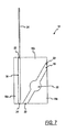
- the lance 24 may be located at an angle relative to the capillary channel 18 (such as shown in another alternative embodiment depicted in FIG. 7 ) or it may be located directly above the capillary channel 18 (shown in FIGS. 5 and 6 ).
- Other embodiments are contemplated having the second end 22 of the capillary channel 18 adjacent to the puncture wound, but having different orientations for the lance 24 and the capillary channel 18.
- the guide 28 is used to move the lance 24 between the first and second positions shown in FIGS. 4a and 4b .
- the lance When in the second position, the lance will pierce the skin for drawing blood, creating a puncture wound. Because the second end 22 of the capillary channel 18 is adjacent to the puncture wound, blood will flow from the wound into the capillary channel 18 via capillary action without any manual moving of the fluid collection apparatus 10.
- the lance 24 only needs to be pulled out of the skin, but does not need to be pulled completely out of the capillary channel 18, since the lance's location will not prevent the blood from entering the capillary channel 18. Since the guide 28 is wider than the lance 24, the guide 28 may be easier for some users to grasp and use than the prior embodiment.
- the lance 24 is disposed in a lance channel 30, having a first end 32 and a second end 34.
- the lance channel 30 is formed by first and second spacers 16a, 16b.
- the capillary channel 18 is formed by the second spacer 16b and a third spacer 16c.
- the lance 24 is moveable within the lance channel 30 in a direction parallel to the length of the channel 30.
- the lance channel 30 is disposed such that the second end 34 of the lance channel 30 is adjacent to the second end 22 of the capillary channel 18.
- the fluid collection apparatus 10 is placed against the skin as in the other embodiments.
- the lance 24 is then pushed downward through the lance channel 30 and into the skin.
- the lance 24 is withdrawn from the skin, but remains within the lance channel 30.
- the blood is then drawn into the capillary channel 18, via capillary action.
- the lance channel 30 is not able to draw any blood into it, and all of the blood is instead drawn into the adjacent capillary channel 18.
- at least one face of the lance channel 30 can be of a hydrophobic material that inhibits entry of the blood into the lance channel 30.
- the capillary channel 18 includes the detection area 26.
- the reagent 19 is kept in the detection area 26, creating the measurable reaction in the detection area 26.
Abstract
Description
- The present invention relates generally to blood monitoring devices and, more particularly, to a sensor having an integrated lance.
- It is often necessary to quickly obtain a sample of blood and perform an analysis of the blood sample. One example of a need for quickly obtaining a sample of blood is in connection with a blood glucose monitoring system where a user must frequently use the system to monitor the user's blood glucose level.
- Those who have irregular blood glucose concentration levels are often medically required to self-monitor their blood glucose concentration level. An irregular blood glucose level can be brought on by a variety of reasons including illness, such as diabetes. The purpose of monitoring the blood glucose concentration level is to determine the blood glucose concentration level and then to take corrective action, based upon whether the level is too high or too low, to bring the level back within a normal range. The failure to take corrective action can have serious implications. When blood glucose levels drop too low, a condition known as hypoglycemia, a person can become nervous, shaky, and confused. That person's judgment may become impaired and that person may eventually pass out. A person can also become very ill if their blood glucose level becomes too high, a condition known as hyperglycemia. Both conditions, hypoglycemia and hyperglycemia, are potentially life-threatening emergencies.
- One method of monitoring a person's blood glucose level is with a portable, handheld blood glucose testing device. A prior art blood
glucose testing device 100 is illustrated inFIG. 1 . The portable nature of thesedevices 100 enables the users to conveniently test their blood glucose levels wherever the user may be. The glucose testing device contains atest sensor 102 to harvest the blood for analysis. Thedevice 100 contains a switch 104 to activate thedevice 100 and adisplay 106 to display the blood glucose analysis results. In order to check the blood glucose level, a drop of blood is obtained from the fingertip using a lancing device. A priorart lancing device 120 is illustrated inFIG. 2 . Thelancing device 120 contains aneedle lance 122 to puncture the skin. Some lancing devices implement a vacuum to facilitate drawing blood. Once the requisite amount of blood is produced on the fingertip, the blood is harvested using thetest sensor 102. Thetest sensor 102, which is inserted into atesting unit 100, is brought into contact with the blood drop. Thetest sensor 102 draws the blood to the inside of itself. The test sensor, in combination with the testing unit, then determines the concentration of glucose in the blood. Once the results of the test are displayed on thedisplay 106 of thetest device 100, thetest sensor 102 is discarded. Each new test requires anew test sensor 102. - One problem associated with current test devices is that the test device comprises a two step operation for sample generation and sample harvesting/reading. The two operations are accomplished with two separate instruments (a lance and a test sensor), each having a separate disposable. This requires more parts and more work for the user in disposing the parts.
- Another problem associated with current test devices is the difficulty in harvesting small samples when the test sensor is separate from the lance. There is a trend in glucose testing towards minimizing the sample volume. This trend is based on the assumption that there is a corresponding reduction in pain when less sample volume is acquired. As the sample volume is reduced, it becomes more difficult to manually manipulate the test sensor in order to harvest the blood. This is especially true for people who may have seeing impairments or other disabilities, making it difficult to manipulate the test sensor within a small area.
- Another problem associated with obtaining small sample sizes is related to the precision needed to obtain the samples. When only small amounts of blood are produced by the lance, it is important that the entire sample or most of the sample be drawn into the test device. When larger volumes of blood are drawn, it is less necessary to obtain all of the blood for the sensor. In small volume test devices, it is important that the sensor be located very near to the puncture wound to maximize the amount of blood that is drawn into the sensor for testing. In current test devices, where the sensor has to be manually moved to the puncture wound, it may be difficult to get close enough to the wound to obtain enough of the sample.
- Some current test devices utilize an integrated sensor and lance. The lance is perpendicular to the plane of the test sensor and penetrates through the sensor surface. These sensors, however, still experience the problem that the test sensor must be manually manipulated after the lancing operation is performed.
- Another test device has been developed for the collection of interstitial fluid (ISF) that utilizes an integrated lance and reaction area. ISF is collected by piercing just below the skin before any nerve endings or any capillaries. Collecting ISF is sometimes desirable because there is no pain involved since it is above any nerve endings. The lance in this test device is not strong enough to pierce through the dermal layer of the skin in order to obtain samples of other fluids, such as blood. One disadvantage of this and other integrated systems is that the user is forced to dispose of the lance with each test device, an additional expense, as most users reuse their lancets a number of times. A second disadvantage is that any reagent in the device is necessarily exposed to extreme conditions during the required sterilization of the lance. Such exposure may affect the performance of the device.
- The present invention is a fluid collection apparatus adapted to test a concentration of an analyte in a fluid and includes a lid and a base. The fluid collection apparatus further includes a spacer disposed between the lid and the base. The spacer forms a capillary channel, which has an opening and is designed to collect the fluid. The capillary channel also includes a reagent that reacts with the fluid to produce a measurable reaction. The reaction will indicate the concentration of the analyte in the fluid. Coupled to the lid is a lance that is moveable to the base and is moveable to a position adjacent the opening of the capillary channel.
- The above summary of the present invention is not intended to represent each embodiment, or every aspect, of the present invention. This is the purpose of the figures and the detailed description which follow.
- The foregoing and other advantages of the invention will become apparent upon reading the following detailed description and upon reference to the drawings.
-
FIG. 1 is a top view of a prior art blood glucose testing device. -
FIG. 2 is a perspective view of a prior art lance. -
FIG. 3 is a top end view of a test device according to one embodiment of the present invention. -
FIG. 4a is a front view of a test device having a cover removed according to one embodiment of the present invention. -
FIG. 4b is a front view of a test device having a cover removed according to another embodiment of the present invention. -
FIG. 5 is a side view of a test device according to one embodiment of the present invention. -
FIG. 6 is a top view of the test device ofFIG. 5 . -
FIG. 7 is a top view of the test device according to another embodiment of the present invention. - While the invention is susceptible to various modifications and alternative forms, specific embodiments have been shown by way of example in the drawings and will be described in detail herein. It should be understood, however, that the invention is not intended to be limited to the particular forms disclosed. Rather, the invention is to cover all modifications, equivalents, and alternatives falling within the spirit and scope of the invention as defined by the appended claims.
-
FIG. 3 depicts afluid collection apparatus 10 according to one embodiment of the present invention. Thefluid collection apparatus 10 is designed to collect a fluid, such as blood, so the fluid may be tested for the concentration of a particular analyte, such as glucose. In describing the details of the operation of thefluid collection apparatus 10, the fluid described will be blood pricked from a finger and the analyte will be glucose. It is understood that the embodiment may also be used for other fluids and analytes and that these only serve as examples. - The
fluid collection apparatus 10 includes alid 12, abase 14, and a pair ofspacers lid 12 and thebase 14. The pair ofspacers capillary channel 18. In the illustrated embodiment, thecapillary channel 18 is elongated and spans the entire length of the spacers (shown inFIG. 4a ). Thecapillary channel 18 has afirst end 20 and a second end 22 (shown inFIG. 4a ). Thecapillary channel 18 includes a reagent 19 that will react with the drawn blood in order to create a measurable reaction. According to one embodiment, the reagent 19 is disbursed throughout the entire capillary channel. Alance 24 is disposed in thecapillary channel 18. Thelance 24 is moveable through thecapillary channel 18 in a direction parallel to the length of thecapillary channel 18. - In one embodiment, the
fluid collection apparatus 10 can be used in conjunction with a photometric test device to measure the concentration of the analyte directly, for example, by the absorption of light in the infrared region. The test device would measure the amount of infrared light absorbed. Alternatively, a reagent 19 can be used that causes a change in color in the capillary channel. The photometric test device then reads the amount of color change. Photometric testing is described in more detail in commonly-ownedU.S. Patent No. 5,611,999 entitled "Diffuse Reflectance Readhead" which is incorporated herein by reference in its entirety. It is also contemplated that other methods of measuring the concentration of glucose in blood may be utilized. - In another embodiment of the
fluid collection apparatus 10, an electrochemical test device is employed as shown inFIG. 4b . Thecapillary channel 18 includes a pair ofelectrodes 25. In electrochemical analysis, the change in current across theelectrodes 25 caused by the reaction of the glucose and the reagent 19 creates an oxidation current at theelectrodes 25 which is directly proportional to the user's blood glucose concentration. The current can be measured by an electrochemical test device coupled to a pair of terminals (not shown) corresponding to theelectrodes 25. The electrochemical test device can then communicate to the user the blood glucose concentration. An example of an electrochemical test system is described in detail by commonly-ownedU.S. Patent No. 5,723,284 entitled "Control Solution And Method For Testing The Performance Of An Electrochemical Device For Determining The Concentration Of An Analyte In Blood" which is incorporated herein by reference in its entirety. - Turning now to
FIG. 4a , a top view of thefluid collection apparatus 10 with thelid 12 removed is shown. As can be seen in this view, thelance 24 extends through thecapillary channel 18 and out of thefirst end 20. The reagent 19 may be placed anywhere within thecapillary channel 18. - In
FIG. 4b , an alternative embodiment of thefluid collection apparatus 10 is shown. In this embodiment, thecapillary channel 18 includes adetection area 26. Thedetection area 26 may be a reaction area that includes the reagent 19 and is slightly wider than the rest of thecapillary channel 18. The enlarged area makes viewing easier and is used with some optical sensors. - In one embodiment, the
capillary channel 18 is from approximately 0.020 to approximately 0.040 inches in length and from approximately 0.006 to approximately 0.012 inches in width. Thelance 24 is from approximately 0.005 to approximately 0.011 inches in diameter. Thedetection area 26 has an area of approximately 0.7 x 10⁻³ to approximately 10 x 10-3 inches squared. - The operation of the
device 10 illustrated in the embodiments ofFIGS. 3-4b will now be described. A user will position the apparatus such that thesecond end 22 of thecapillary channel 18 is pressed against the skin. Thelance 24 is in a first position, shown inFIG. 4a , extending out from thefirst end 20 of thecapillary channel 18. The user then pushes thelance 24 downward to a second position shown inFIG. 4b , such that thelance 24 extends past thesecond opening 22 of thecapillary channel 18 and enters the skin. Thelance 24 is pushed downward with enough force to create a puncture wound sufficient to draw blood. Thelance 24 has a length greater than thecapillary channel 18, allowing thelance 24 to extend past both the first and the second ends 20, 22 of thecapillary channel 18. Once thelance 24 has punctured the skin, the user pullslance 24 out of the skin and up thecapillary channel 18, at least past thereaction area 26. Blood is drawn into thecapillary channel 18 via capillary action. The reagent 19 in thecapillary channel 18 reacts with the blood to create a reaction that can be measured as discussed above. In some embodiments, thecapillary channel 18 includes stops (not shown) that prevent thelance 24 from being completely pulled out of thecapillary channel 18. In these embodiments, it is only necessary to pull the lance past the location of the reagent 19. - The
fluid collection apparatus 10 as described provides the advantage of placing the harvesting or collection point of the sensor at the same location as the puncture wound from thelance 24. This eliminates the need to move thefluid collection apparatus 10 around after drawing blood in order to harvest the blood. Thedevice 10 is easier to use, because the users will not have to manually manipulate the sensor after the puncture by trying to place the sensor at the precise location of the puncture. - Turning now to
FIGS. 5 and 6 , another embodiment of the present invention will be shown. Like reference numerals will be used to identify like structures. In this embodiment, thefluid collection apparatus 10 includes thebase 14, the pair ofspacers capillary channel 18 that is defined by thespacers lid 12, and thelance 24. Alternatively, the base and the spacers or the lid and the spacers can be combined into a single piece that has been molded or formed to this three dimensional shape. In the embodiment shown inFIG. 6 , thefluid collection apparatus 10 includes adetection area 26. Thedetection area 26 may be a specific reaction area including the reagent 19. Alternatively, the reagent 19 is dispersed throughout the entirecapillary channel 18. In another embodiment, there is no reagent and an infrared detector may be used to measure the absorption of infrared light. - The
collection apparatus 10 also includes aguide 28 for moving the lance. Theguide 28 is slidably engaged to thebase 14, thespacers lid 12. Theguide 28 is moveable in a direction parallel to the length of thecapillary channel 18. Theguide 28 is attached to thelance 24. In this embodiment, thelance 24 is not disposed inside thecapillary channel 18 but, instead, is adjacent to thecapillary channel 18. - The
lance 24 is disposed so that it will draw blood at a location adjacent to thesecond end 22 of thecapillary channel 18. Thelance 24 may be located at an angle relative to the capillary channel 18 (such as shown in another alternative embodiment depicted inFIG. 7 ) or it may be located directly above the capillary channel 18 (shown inFIGS. 5 and 6 ). Other embodiments are contemplated having thesecond end 22 of thecapillary channel 18 adjacent to the puncture wound, but having different orientations for thelance 24 and thecapillary channel 18. - Returning now to the description relating to
FIGS. 5 and 6 , theguide 28 is used to move thelance 24 between the first and second positions shown inFIGS. 4a and 4b . When in the second position, the lance will pierce the skin for drawing blood, creating a puncture wound. Because thesecond end 22 of thecapillary channel 18 is adjacent to the puncture wound, blood will flow from the wound into thecapillary channel 18 via capillary action without any manual moving of thefluid collection apparatus 10. In this embodiment, thelance 24 only needs to be pulled out of the skin, but does not need to be pulled completely out of thecapillary channel 18, since the lance's location will not prevent the blood from entering thecapillary channel 18. Since theguide 28 is wider than thelance 24, theguide 28 may be easier for some users to grasp and use than the prior embodiment. - Turning now to
FIG. 7 , another embodiment of the present invention will be described. In this embodiment, thelance 24 is disposed in alance channel 30, having afirst end 32 and asecond end 34. Thelance channel 30 is formed by first andsecond spacers capillary channel 18 is formed by thesecond spacer 16b and athird spacer 16c. Thelance 24 is moveable within thelance channel 30 in a direction parallel to the length of thechannel 30. Thelance channel 30 is disposed such that thesecond end 34 of thelance channel 30 is adjacent to thesecond end 22 of thecapillary channel 18. - In operation, the
fluid collection apparatus 10 is placed against the skin as in the other embodiments. Thelance 24 is then pushed downward through thelance channel 30 and into the skin. After the skin is punctured, thelance 24 is withdrawn from the skin, but remains within thelance channel 30. The blood is then drawn into thecapillary channel 18, via capillary action. By keeping thelance 24 in thelance channel 30, thelance channel 30 is not able to draw any blood into it, and all of the blood is instead drawn into the adjacentcapillary channel 18. Alternatively, at least one face of thelance channel 30 can be of a hydrophobic material that inhibits entry of the blood into thelance channel 30. - In the illustrated embodiment, the
capillary channel 18 includes thedetection area 26. In this embodiment, the reagent 19 is kept in thedetection area 26, creating the measurable reaction in thedetection area 26. In some embodiments, there will not be a specific,enlarged detection area 26 and the reagent 19 will be dispersed elsewhere in thecapillary channel 18. - While the present invention has been described with reference to one or more particular embodiments, those skilled in the art will recognize that many changes may be made thereto without departing from the spirit and scope of the present invention. Each of these embodiments and obvious variations thereof is contemplated as falling within the spirit and scope of the claimed invention, which is set forth in the following claims.
Claims (15)
- A fluid collection apparatus (10) adapted to test a concentration of an analyte in a fluid, comprising:a base (14);a spacer (16a, 16b) disposed between said base (14) and said guide (28), said spacer (16a, 16b) assisting in forming a capillary channel (18) having an opening (22) for receiving the fluid; anda lance (24) movable relative to said base (14) between a first position and a second position, an end of said lance (24), in said second position, extending beyond said base (14) for puncturing,
characterized in that
said lance (24) is coupled to a guide (26), said guide (28) causing said movement of said lance (24) between said first position and said second position, and in that said end of said lance (24), in said second position, is positioned at a location from which said capillary channel (18) can draw fluid via said opening (22) by capillary action. - The fluid collection apparatus (10) of claim 1, wherein said glide (28) is slidably engaged to said base (14) or said spacer (16a, 16b).
- The fluid collection apparatus (10) of claim 1, further comprising a lid (12), said lid (12) being disposed between said spacer (16a, 16b) and said guide (28).
- The fluid collection apparatus (10) of claim 3, wherein said glide (28) is slidably engaged to said base (14), said spacer (16a, 16b), or said lid (12).
- The fluid collection apparatus (10) of one of the claims 1 to 4, wherein said end of said lance (24), in said second position, is adjacent to said opening (22) of said capillary channel (18).
- The fluid collection apparatus (10) of one of the claims 1 to 5, wherein said guide (28) is moveable in a direction parallel to said capillary channel (18).
- The fluid collection apparatus (10) of one of the claims 1 to 6, wherein said lance (24) is moveable between said first position and said second position in a direction parallel to said capillary channel (18).
- The fluid collection apparatus (10) of one of the claims 1 to 6, wherein said lance (24) is disposed at an acute angle relative to said capillary channel (18).
- The fluid collection apparatus (10) of one of the claims 1 to 8, further comprising a reagent (19) disposed in said capillary channel (18) and adapted to produce a reaction indicative of the concentration of the analyte in the fluid.
- The fluid collection apparatus (10) of claim 9, wherein said capillary channel (18) forms a detection area (26), said detection area (26) containing said reagent (19) and being wider than other sections of said capillary channel (18).
- The fluid collection apparatus (10) of claim 10, wherein said detection area (26) has an area of approximately 0.45 mm2 (0.7 x 10⁻⁴ in2) to 6.45 mm2 (1.0 x 10⁻² in2).
- The fluid collection apparatus (10) of claim 9, wherein said reagent (19) is adapted to produce a colorimetric reaction or an electrochemical reaction.
- The fluid collection apparatus (10) of one of the claims 1 to 12, wherein said capillary channel (18) has a length of approximately 0.508 mm (0.020 in) to approximately 1.016 mm (0.040 in).
- The fluid collection apparatus (10) of one of the claims 1 to 13, wherein said capillary channel (18) has a width of approximately 0.13 mm (0.005 in) to approximately 0.28 mm (0.011 in).
- The fluid collection apparatus (10) of one of the claims 1 to 14, wherein said lance (24) has a diameter of approximately 0.13 mm (0.005 in) to approximately 0.28 mm (0.011 in).
Applications Claiming Priority (3)
| Application Number | Priority Date | Filing Date | Title |
|---|---|---|---|
| US39110802P | 2002-06-25 | 2002-06-25 | |
| EP07013176A EP1839577B1 (en) | 2002-06-25 | 2003-06-25 | Sensor with integrated lancet |
| EP03014233A EP1374770B2 (en) | 2002-06-25 | 2003-06-25 | Sensor with integrated lancet |
Related Parent Applications (3)
| Application Number | Title | Priority Date | Filing Date |
|---|---|---|---|
| EP03014233.5 Division | 2003-06-25 | ||
| EP07013176A Division EP1839577B1 (en) | 2002-06-25 | 2003-06-25 | Sensor with integrated lancet |
| EP07013176.8 Division | 2007-07-05 |
Publications (2)
| Publication Number | Publication Date |
|---|---|
| EP2080476A1 true EP2080476A1 (en) | 2009-07-22 |
| EP2080476B1 EP2080476B1 (en) | 2012-08-08 |
Family
ID=29584652
Family Applications (3)
| Application Number | Title | Priority Date | Filing Date |
|---|---|---|---|
| EP09005552A Expired - Lifetime EP2080476B1 (en) | 2002-06-25 | 2003-06-25 | Sensor with integrated lancet |
| EP03014233A Expired - Lifetime EP1374770B2 (en) | 2002-06-25 | 2003-06-25 | Sensor with integrated lancet |
| EP07013176A Expired - Lifetime EP1839577B1 (en) | 2002-06-25 | 2003-06-25 | Sensor with integrated lancet |
Family Applications After (2)
| Application Number | Title | Priority Date | Filing Date |
|---|---|---|---|
| EP03014233A Expired - Lifetime EP1374770B2 (en) | 2002-06-25 | 2003-06-25 | Sensor with integrated lancet |
| EP07013176A Expired - Lifetime EP1839577B1 (en) | 2002-06-25 | 2003-06-25 | Sensor with integrated lancet |
Country Status (14)
| Country | Link |
|---|---|
| EP (3) | EP2080476B1 (en) |
| JP (1) | JP4798940B2 (en) |
| KR (1) | KR101035839B1 (en) |
| AT (1) | ATE439086T1 (en) |
| AU (1) | AU2003204930B2 (en) |
| CA (1) | CA2432624C (en) |
| DE (2) | DE60317736T3 (en) |
| DK (3) | DK2080476T3 (en) |
| ES (2) | ES2329944T3 (en) |
| IL (1) | IL156592A0 (en) |
| NO (1) | NO20032890L (en) |
| NZ (1) | NZ526334A (en) |
| TW (1) | TWI310834B (en) |
| ZA (1) | ZA200304897B (en) |
Cited By (1)
| Publication number | Priority date | Publication date | Assignee | Title |
|---|---|---|---|---|
| US9776296B2 (en) | 2008-05-09 | 2017-10-03 | Milwaukee Electric Tool Corporation | Power tool dust collector |
Families Citing this family (44)
| Publication number | Priority date | Publication date | Assignee | Title |
|---|---|---|---|---|
| US8641644B2 (en) | 2000-11-21 | 2014-02-04 | Sanofi-Aventis Deutschland Gmbh | Blood testing apparatus having a rotatable cartridge with multiple lancing elements and testing means |
| CA2435439A1 (en) | 2001-01-22 | 2002-07-25 | F. Hoffmann-La Roche Ag | Lancet device having capillary action |
| US7310543B2 (en) | 2001-03-26 | 2007-12-18 | Kumetrix, Inc. | Silicon microprobe with integrated biosensor |
| US9795747B2 (en) | 2010-06-02 | 2017-10-24 | Sanofi-Aventis Deutschland Gmbh | Methods and apparatus for lancet actuation |
| US9226699B2 (en) | 2002-04-19 | 2016-01-05 | Sanofi-Aventis Deutschland Gmbh | Body fluid sampling module with a continuous compression tissue interface surface |
| US7041068B2 (en) | 2001-06-12 | 2006-05-09 | Pelikan Technologies, Inc. | Sampling module device and method |
| US9427532B2 (en) | 2001-06-12 | 2016-08-30 | Sanofi-Aventis Deutschland Gmbh | Tissue penetration device |
| DE10134650B4 (en) | 2001-07-20 | 2009-12-03 | Roche Diagnostics Gmbh | System for taking small amounts of body fluid |
| DE10142232B4 (en) | 2001-08-29 | 2021-04-29 | Roche Diabetes Care Gmbh | Process for the production of an analytical aid with a lancet and test element |
| US9248267B2 (en) | 2002-04-19 | 2016-02-02 | Sanofi-Aventis Deustchland Gmbh | Tissue penetration device |
| US9314194B2 (en) | 2002-04-19 | 2016-04-19 | Sanofi-Aventis Deutschland Gmbh | Tissue penetration device |
| US8579831B2 (en) | 2002-04-19 | 2013-11-12 | Sanofi-Aventis Deutschland Gmbh | Method and apparatus for penetrating tissue |
| US7547287B2 (en) | 2002-04-19 | 2009-06-16 | Pelikan Technologies, Inc. | Method and apparatus for penetrating tissue |
| US8702624B2 (en) | 2006-09-29 | 2014-04-22 | Sanofi-Aventis Deutschland Gmbh | Analyte measurement device with a single shot actuator |
| US9795334B2 (en) | 2002-04-19 | 2017-10-24 | Sanofi-Aventis Deutschland Gmbh | Method and apparatus for penetrating tissue |
| US8784335B2 (en) | 2002-04-19 | 2014-07-22 | Sanofi-Aventis Deutschland Gmbh | Body fluid sampling device with a capacitive sensor |
| US7226461B2 (en) | 2002-04-19 | 2007-06-05 | Pelikan Technologies, Inc. | Method and apparatus for a multi-use body fluid sampling device with sterility barrier release |
| US7815579B2 (en) | 2005-03-02 | 2010-10-19 | Roche Diagnostics Operations, Inc. | Dynamic integrated lancing test strip with sterility cover |
| US8574895B2 (en) | 2002-12-30 | 2013-11-05 | Sanofi-Aventis Deutschland Gmbh | Method and apparatus using optical techniques to measure analyte levels |
| WO2006001797A1 (en) | 2004-06-14 | 2006-01-05 | Pelikan Technologies, Inc. | Low pain penetrating |
| WO2005033659A2 (en) | 2003-09-29 | 2005-04-14 | Pelikan Technologies, Inc. | Method and apparatus for an improved sample capture device |
| US9351680B2 (en) | 2003-10-14 | 2016-05-31 | Sanofi-Aventis Deutschland Gmbh | Method and apparatus for a variable user interface |
| EP1706026B1 (en) | 2003-12-31 | 2017-03-01 | Sanofi-Aventis Deutschland GmbH | Method and apparatus for improving fluidic flow and sample capture |
| EP1725867A4 (en) * | 2004-03-18 | 2009-04-08 | Fujifilm Corp | Analysis element for use in method of testing specimen |
| US8828203B2 (en) | 2004-05-20 | 2014-09-09 | Sanofi-Aventis Deutschland Gmbh | Printable hydrogels for biosensors |
| US9820684B2 (en) | 2004-06-03 | 2017-11-21 | Sanofi-Aventis Deutschland Gmbh | Method and apparatus for a fluid sampling device |
| US9775553B2 (en) | 2004-06-03 | 2017-10-03 | Sanofi-Aventis Deutschland Gmbh | Method and apparatus for a fluid sampling device |
| US7935063B2 (en) | 2005-03-02 | 2011-05-03 | Roche Diagnostics Operations, Inc. | System and method for breaking a sterility seal to engage a lancet |
| US7695442B2 (en) | 2005-04-12 | 2010-04-13 | Roche Diagnostics Operations, Inc. | Integrated lancing test strip with retractable lancet |
| EP1709906A1 (en) * | 2005-04-07 | 2006-10-11 | F. Hoffmann-La Roche Ag | Method and device for blood sampling |
| JP2009542304A (en) | 2006-07-06 | 2009-12-03 | ラピッディックス エルティーディー. | Integrated blood collection and test instrument and method of use |
| EP1970006A1 (en) | 2007-03-14 | 2008-09-17 | Roche Diagnostics GmbH | Analysis system for determining a analyte in a body fluid and disposable integrated sample extraction and analysis element |
| WO2009081405A2 (en) | 2007-12-25 | 2009-07-02 | Rapidx Ltd. | Devices and methods for reduced-pain blood sampling |
| WO2009126900A1 (en) | 2008-04-11 | 2009-10-15 | Pelikan Technologies, Inc. | Method and apparatus for analyte detecting device |
| US8967923B2 (en) | 2012-01-13 | 2015-03-03 | Aeg Electric Tools Gmbh | Dust suction device for drilling machine |
| US9375169B2 (en) | 2009-01-30 | 2016-06-28 | Sanofi-Aventis Deutschland Gmbh | Cam drive for managing disposable penetrating member actions with a single motor and motor and control system |
| MX336273B (en) * | 2009-05-14 | 2016-01-13 | Biotechnology Inst I Mas D Sl | Method for preparing at least one compound from blood, and sampling device for use when carrying out said method. |
| JP5668215B2 (en) * | 2009-12-08 | 2015-02-12 | パナソニックヘルスケアホールディングス株式会社 | Biological information measuring device |
| US20130131479A1 (en) | 2010-03-19 | 2013-05-23 | John Michael Kelly | Diagnostic system |
| US20120238841A1 (en) * | 2010-04-15 | 2012-09-20 | Mark Castle | Sample capture in one step for test strips |
| US8965476B2 (en) | 2010-04-16 | 2015-02-24 | Sanofi-Aventis Deutschland Gmbh | Tissue penetration device |
| MY166817A (en) * | 2010-10-15 | 2018-07-23 | Atomo Diagnostics Pty Ltd | Sampling assembly |
| CN102507552B (en) * | 2011-10-24 | 2013-06-12 | 北京市药品检验所 | Method for rapidly detecting tadalafil or derivatives thereof |
| EP3071967B1 (en) | 2013-11-21 | 2019-05-08 | Atomo Diagnostics Pty Limited | Fluid control in integrated testing devices |
Citations (6)
| Publication number | Priority date | Publication date | Assignee | Title |
|---|---|---|---|---|
| US5611999A (en) | 1995-09-05 | 1997-03-18 | Bayer Corporation | Diffused light reflectance readhead |
| US5723284A (en) | 1996-04-01 | 1998-03-03 | Bayer Corporation | Control solution and method for testing the performance of an electrochemical device for determining the concentration of an analyte in blood |
| GB2331935A (en) * | 1997-12-04 | 1999-06-09 | Hewlett Packard Co | Cartridge for sampling blood |
| US6120676A (en) * | 1997-02-06 | 2000-09-19 | Therasense, Inc. | Method of using a small volume in vitro analyte sensor |
| US6132449A (en) * | 1999-03-08 | 2000-10-17 | Agilent Technologies, Inc. | Extraction and transportation of blood for analysis |
| EP1174083A2 (en) * | 2000-07-10 | 2002-01-23 | Bayer Corporation | Thin lance and test sensor having the same |
Family Cites Families (13)
| Publication number | Priority date | Publication date | Assignee | Title |
|---|---|---|---|---|
| US4627445A (en) * | 1985-04-08 | 1986-12-09 | Garid, Inc. | Glucose medical monitoring system |
| JPS61286738A (en) * | 1985-06-14 | 1986-12-17 | オ−デイオバイオニクス インコ−ポレイテツド | Medical system |
| AUPN363995A0 (en) † | 1995-06-19 | 1995-07-13 | Memtec Limited | Electrochemical cell |
| JPH09168530A (en) * | 1995-10-17 | 1997-06-30 | Dainippon Printing Co Ltd | Body fluid collecting tool and body fluid analyzer using the same |
| DE19758808B4 (en) * | 1996-05-17 | 2009-11-26 | Roche Diagnostics Operations Inc. (N.D.Ges.D.Staates Delaware), Indianapolis | Sampling device for body fluid |
| US5879311A (en) † | 1996-05-17 | 1999-03-09 | Mercury Diagnostics, Inc. | Body fluid sampling device and methods of use |
| US5971941A (en) † | 1997-12-04 | 1999-10-26 | Hewlett-Packard Company | Integrated system and method for sampling blood and analysis |
| US5975153A (en) * | 1998-02-13 | 1999-11-02 | Roche Diagnostics Corporation | Capillary fill test device with improved fluid delivery |
| JP3398598B2 (en) * | 1998-06-10 | 2003-04-21 | 松下電器産業株式会社 | Substrate quantification method and analytical element and measuring device used for the method |
| JP3633317B2 (en) * | 1998-10-22 | 2005-03-30 | ニプロ株式会社 | Blood test tool with puncture needle |
| CN1191786C (en) * | 1999-01-04 | 2005-03-09 | 泰尔茂株式会社 | Assembly having lancet and means for collecting and detecting body fluid |
| JP2000258382A (en) † | 1999-03-05 | 2000-09-22 | Arkray Inc | Specimen small-quantity-type bio sensor |
| US6612111B1 (en) * | 2000-03-27 | 2003-09-02 | Lifescan, Inc. | Method and device for sampling and analyzing interstitial fluid and whole blood samples |
-
2003
- 2003-06-06 NZ NZ526334A patent/NZ526334A/en unknown
- 2003-06-16 KR KR1020030038627A patent/KR101035839B1/en not_active IP Right Cessation
- 2003-06-17 CA CA2432624A patent/CA2432624C/en not_active Expired - Fee Related
- 2003-06-19 TW TW092116655A patent/TWI310834B/en not_active IP Right Cessation
- 2003-06-23 NO NO20032890A patent/NO20032890L/en not_active Application Discontinuation
- 2003-06-23 IL IL15659203A patent/IL156592A0/en unknown
- 2003-06-24 ZA ZA200304897A patent/ZA200304897B/en unknown
- 2003-06-24 JP JP2003178982A patent/JP4798940B2/en not_active Expired - Fee Related
- 2003-06-25 EP EP09005552A patent/EP2080476B1/en not_active Expired - Lifetime
- 2003-06-25 DE DE60317736T patent/DE60317736T3/en not_active Expired - Lifetime
- 2003-06-25 EP EP03014233A patent/EP1374770B2/en not_active Expired - Lifetime
- 2003-06-25 DK DK09005552.6T patent/DK2080476T3/en active
- 2003-06-25 ES ES07013176T patent/ES2329944T3/en not_active Expired - Lifetime
- 2003-06-25 DK DK03014233.5T patent/DK1374770T4/en active
- 2003-06-25 ES ES03014233T patent/ES2297077T3/en not_active Expired - Lifetime
- 2003-06-25 DE DE60328840T patent/DE60328840D1/en not_active Expired - Lifetime
- 2003-06-25 EP EP07013176A patent/EP1839577B1/en not_active Expired - Lifetime
- 2003-06-25 DK DK07013176T patent/DK1839577T3/en active
- 2003-06-25 AT AT07013176T patent/ATE439086T1/en not_active IP Right Cessation
- 2003-06-25 AU AU2003204930A patent/AU2003204930B2/en not_active Ceased
Patent Citations (6)
| Publication number | Priority date | Publication date | Assignee | Title |
|---|---|---|---|---|
| US5611999A (en) | 1995-09-05 | 1997-03-18 | Bayer Corporation | Diffused light reflectance readhead |
| US5723284A (en) | 1996-04-01 | 1998-03-03 | Bayer Corporation | Control solution and method for testing the performance of an electrochemical device for determining the concentration of an analyte in blood |
| US6120676A (en) * | 1997-02-06 | 2000-09-19 | Therasense, Inc. | Method of using a small volume in vitro analyte sensor |
| GB2331935A (en) * | 1997-12-04 | 1999-06-09 | Hewlett Packard Co | Cartridge for sampling blood |
| US6132449A (en) * | 1999-03-08 | 2000-10-17 | Agilent Technologies, Inc. | Extraction and transportation of blood for analysis |
| EP1174083A2 (en) * | 2000-07-10 | 2002-01-23 | Bayer Corporation | Thin lance and test sensor having the same |
Cited By (1)
| Publication number | Priority date | Publication date | Assignee | Title |
|---|---|---|---|---|
| US9776296B2 (en) | 2008-05-09 | 2017-10-03 | Milwaukee Electric Tool Corporation | Power tool dust collector |
Also Published As
| Publication number | Publication date |
|---|---|
| JP2004249078A (en) | 2004-09-09 |
| DK2080476T3 (en) | 2012-11-12 |
| AU2003204930B2 (en) | 2009-05-28 |
| DE60317736T2 (en) | 2008-11-27 |
| ES2329944T3 (en) | 2009-12-02 |
| DK1374770T4 (en) | 2011-11-21 |
| EP1839577A1 (en) | 2007-10-03 |
| AU2003204930A1 (en) | 2004-01-22 |
| NO20032890D0 (en) | 2003-06-23 |
| DE60328840D1 (en) | 2009-09-24 |
| EP1839577B1 (en) | 2009-08-12 |
| KR20040002562A (en) | 2004-01-07 |
| TWI310834B (en) | 2009-06-11 |
| CA2432624A1 (en) | 2003-12-25 |
| ES2297077T3 (en) | 2008-05-01 |
| EP1374770A1 (en) | 2004-01-02 |
| EP2080476B1 (en) | 2012-08-08 |
| DK1374770T3 (en) | 2008-04-07 |
| KR101035839B1 (en) | 2011-05-20 |
| ATE439086T1 (en) | 2009-08-15 |
| DE60317736D1 (en) | 2008-01-10 |
| JP4798940B2 (en) | 2011-10-19 |
| NZ526334A (en) | 2003-10-31 |
| CA2432624C (en) | 2013-09-03 |
| EP1374770B2 (en) | 2011-08-10 |
| ZA200304897B (en) | 2004-05-04 |
| TW200415345A (en) | 2004-08-16 |
| EP1374770B1 (en) | 2007-11-28 |
| DE60317736T3 (en) | 2011-12-15 |
| DK1839577T3 (en) | 2009-11-16 |
| NO20032890L (en) | 2003-12-29 |
| IL156592A0 (en) | 2004-01-04 |
Similar Documents
| Publication | Publication Date | Title |
|---|---|---|
| EP2080476B1 (en) | Sensor with integrated lancet | |
| US20040248312A1 (en) | Sensor with integrated lancet | |
| AU769306B2 (en) | Thin lance and test sensor having same | |
| US6352514B1 (en) | Methods and apparatus for sampling and analyzing body fluid | |
| JP4460840B2 (en) | Method for manufacturing a fluid collection device with integrated puncture needle and reaction zone | |
| US8247233B2 (en) | Integrated fluid analyte meter system | |
| EP1174078A2 (en) | Hollow microneedle patch | |
| EP1875230A1 (en) | Marker for readings taken from alternative site tests | |
| WO2007047812A2 (en) | Analyte-testing instruments having antimicrobial properties and methods of using the same | |
| MXPA06008847A (en) | Method and apparatus for measuring an analyte in a body fluid |
Legal Events
| Date | Code | Title | Description |
|---|---|---|---|
| PUAI | Public reference made under article 153(3) epc to a published international application that has entered the european phase |
Free format text: ORIGINAL CODE: 0009012 |
|
| AC | Divisional application: reference to earlier application |
Ref document number: 1839577 Country of ref document: EP Kind code of ref document: P Ref document number: 1374770 Country of ref document: EP Kind code of ref document: P |
|
| AK | Designated contracting states |
Kind code of ref document: A1 Designated state(s): AT BE BG CH CY CZ DE DK EE ES FI FR GB GR HU IE IT LI LU MC NL PT RO SE SI SK TR |
|
| 17P | Request for examination filed |
Effective date: 20100122 |
|
| 17Q | First examination report despatched |
Effective date: 20100218 |
|
| GRAP | Despatch of communication of intention to grant a patent |
Free format text: ORIGINAL CODE: EPIDOSNIGR1 |
|
| GRAS | Grant fee paid |
Free format text: ORIGINAL CODE: EPIDOSNIGR3 |
|
| GRAA | (expected) grant |
Free format text: ORIGINAL CODE: 0009210 |
|
| AC | Divisional application: reference to earlier application |
Ref document number: 1839577 Country of ref document: EP Kind code of ref document: P Ref document number: 1374770 Country of ref document: EP Kind code of ref document: P |
|
| AK | Designated contracting states |
Kind code of ref document: B1 Designated state(s): AT BE BG CH CY CZ DE DK EE ES FI FR GB GR HU IE IT LI LU MC NL PT RO SE SI SK TR |
|
| REG | Reference to a national code |
Ref country code: GB Ref legal event code: FG4D |
|
| REG | Reference to a national code |
Ref country code: AT Ref legal event code: REF Ref document number: 569296 Country of ref document: AT Kind code of ref document: T Effective date: 20120815 Ref country code: CH Ref legal event code: EP |
|
| REG | Reference to a national code |
Ref country code: IE Ref legal event code: FG4D |
|
| REG | Reference to a national code |
Ref country code: DE Ref legal event code: R096 Ref document number: 60341798 Country of ref document: DE Effective date: 20121004 |
|
| REG | Reference to a national code |
Ref country code: DK Ref legal event code: T3 |
|
| REG | Reference to a national code |
Ref country code: SE Ref legal event code: TRGR |
|
| REG | Reference to a national code |
Ref country code: NL Ref legal event code: VDEP Effective date: 20120808 |
|
| REG | Reference to a national code |
Ref country code: AT Ref legal event code: MK05 Ref document number: 569296 Country of ref document: AT Kind code of ref document: T Effective date: 20120808 |
|
| PG25 | Lapsed in a contracting state [announced via postgrant information from national office to epo] |
Ref country code: CY Free format text: LAPSE BECAUSE OF FAILURE TO SUBMIT A TRANSLATION OF THE DESCRIPTION OR TO PAY THE FEE WITHIN THE PRESCRIBED TIME-LIMIT Effective date: 20120808 Ref country code: AT Free format text: LAPSE BECAUSE OF FAILURE TO SUBMIT A TRANSLATION OF THE DESCRIPTION OR TO PAY THE FEE WITHIN THE PRESCRIBED TIME-LIMIT Effective date: 20120808 |
|
| PG25 | Lapsed in a contracting state [announced via postgrant information from national office to epo] |
Ref country code: GR Free format text: LAPSE BECAUSE OF FAILURE TO SUBMIT A TRANSLATION OF THE DESCRIPTION OR TO PAY THE FEE WITHIN THE PRESCRIBED TIME-LIMIT Effective date: 20121109 Ref country code: BE Free format text: LAPSE BECAUSE OF FAILURE TO SUBMIT A TRANSLATION OF THE DESCRIPTION OR TO PAY THE FEE WITHIN THE PRESCRIBED TIME-LIMIT Effective date: 20120808 Ref country code: SI Free format text: LAPSE BECAUSE OF FAILURE TO SUBMIT A TRANSLATION OF THE DESCRIPTION OR TO PAY THE FEE WITHIN THE PRESCRIBED TIME-LIMIT Effective date: 20120808 Ref country code: PT Free format text: LAPSE BECAUSE OF FAILURE TO SUBMIT A TRANSLATION OF THE DESCRIPTION OR TO PAY THE FEE WITHIN THE PRESCRIBED TIME-LIMIT Effective date: 20121210 |
|
| PG25 | Lapsed in a contracting state [announced via postgrant information from national office to epo] |
Ref country code: NL Free format text: LAPSE BECAUSE OF FAILURE TO SUBMIT A TRANSLATION OF THE DESCRIPTION OR TO PAY THE FEE WITHIN THE PRESCRIBED TIME-LIMIT Effective date: 20120808 |
|
| PG25 | Lapsed in a contracting state [announced via postgrant information from national office to epo] |
Ref country code: CZ Free format text: LAPSE BECAUSE OF FAILURE TO SUBMIT A TRANSLATION OF THE DESCRIPTION OR TO PAY THE FEE WITHIN THE PRESCRIBED TIME-LIMIT Effective date: 20120808 Ref country code: RO Free format text: LAPSE BECAUSE OF FAILURE TO SUBMIT A TRANSLATION OF THE DESCRIPTION OR TO PAY THE FEE WITHIN THE PRESCRIBED TIME-LIMIT Effective date: 20120808 Ref country code: ES Free format text: LAPSE BECAUSE OF FAILURE TO SUBMIT A TRANSLATION OF THE DESCRIPTION OR TO PAY THE FEE WITHIN THE PRESCRIBED TIME-LIMIT Effective date: 20121119 Ref country code: EE Free format text: LAPSE BECAUSE OF FAILURE TO SUBMIT A TRANSLATION OF THE DESCRIPTION OR TO PAY THE FEE WITHIN THE PRESCRIBED TIME-LIMIT Effective date: 20120808 |
|
| PG25 | Lapsed in a contracting state [announced via postgrant information from national office to epo] |
Ref country code: IT Free format text: LAPSE BECAUSE OF FAILURE TO SUBMIT A TRANSLATION OF THE DESCRIPTION OR TO PAY THE FEE WITHIN THE PRESCRIBED TIME-LIMIT Effective date: 20120808 Ref country code: SK Free format text: LAPSE BECAUSE OF FAILURE TO SUBMIT A TRANSLATION OF THE DESCRIPTION OR TO PAY THE FEE WITHIN THE PRESCRIBED TIME-LIMIT Effective date: 20120808 |
|
| PLBE | No opposition filed within time limit |
Free format text: ORIGINAL CODE: 0009261 |
|
| STAA | Information on the status of an ep patent application or granted ep patent |
Free format text: STATUS: NO OPPOSITION FILED WITHIN TIME LIMIT |
|
| 26N | No opposition filed |
Effective date: 20130510 |
|
| PG25 | Lapsed in a contracting state [announced via postgrant information from national office to epo] |
Ref country code: BG Free format text: LAPSE BECAUSE OF FAILURE TO SUBMIT A TRANSLATION OF THE DESCRIPTION OR TO PAY THE FEE WITHIN THE PRESCRIBED TIME-LIMIT Effective date: 20121108 |
|
| REG | Reference to a national code |
Ref country code: DE Ref legal event code: R097 Ref document number: 60341798 Country of ref document: DE Effective date: 20130510 |
|
| PG25 | Lapsed in a contracting state [announced via postgrant information from national office to epo] |
Ref country code: MC Free format text: LAPSE BECAUSE OF FAILURE TO SUBMIT A TRANSLATION OF THE DESCRIPTION OR TO PAY THE FEE WITHIN THE PRESCRIBED TIME-LIMIT Effective date: 20120808 |
|
| GBPC | Gb: european patent ceased through non-payment of renewal fee |
Effective date: 20130625 |
|
| REG | Reference to a national code |
Ref country code: IE Ref legal event code: MM4A |
|
| REG | Reference to a national code |
Ref country code: FR Ref legal event code: ST Effective date: 20140228 |
|
| PG25 | Lapsed in a contracting state [announced via postgrant information from national office to epo] |
Ref country code: IE Free format text: LAPSE BECAUSE OF NON-PAYMENT OF DUE FEES Effective date: 20130625 Ref country code: GB Free format text: LAPSE BECAUSE OF NON-PAYMENT OF DUE FEES Effective date: 20130625 |
|
| PG25 | Lapsed in a contracting state [announced via postgrant information from national office to epo] |
Ref country code: FR Free format text: LAPSE BECAUSE OF NON-PAYMENT OF DUE FEES Effective date: 20130701 |
|
| PG25 | Lapsed in a contracting state [announced via postgrant information from national office to epo] |
Ref country code: TR Free format text: LAPSE BECAUSE OF FAILURE TO SUBMIT A TRANSLATION OF THE DESCRIPTION OR TO PAY THE FEE WITHIN THE PRESCRIBED TIME-LIMIT Effective date: 20120808 |
|
| PG25 | Lapsed in a contracting state [announced via postgrant information from national office to epo] |
Ref country code: HU Free format text: LAPSE BECAUSE OF FAILURE TO SUBMIT A TRANSLATION OF THE DESCRIPTION OR TO PAY THE FEE WITHIN THE PRESCRIBED TIME-LIMIT; INVALID AB INITIO Effective date: 20030625 Ref country code: LU Free format text: LAPSE BECAUSE OF NON-PAYMENT OF DUE FEES Effective date: 20130625 |
|
| PGFP | Annual fee paid to national office [announced via postgrant information from national office to epo] |
Ref country code: FI Payment date: 20160629 Year of fee payment: 14 Ref country code: CH Payment date: 20160627 Year of fee payment: 14 |
|
| PGFP | Annual fee paid to national office [announced via postgrant information from national office to epo] |
Ref country code: DK Payment date: 20160627 Year of fee payment: 14 Ref country code: SE Payment date: 20160629 Year of fee payment: 14 |
|
| PGFP | Annual fee paid to national office [announced via postgrant information from national office to epo] |
Ref country code: DE Payment date: 20160628 Year of fee payment: 14 |
|
| REG | Reference to a national code |
Ref country code: DE Ref legal event code: R119 Ref document number: 60341798 Country of ref document: DE |
|
| REG | Reference to a national code |
Ref country code: DK Ref legal event code: EBP Effective date: 20170630 |
|
| REG | Reference to a national code |
Ref country code: SE Ref legal event code: EUG |
|
| PG25 | Lapsed in a contracting state [announced via postgrant information from national office to epo] |
Ref country code: FI Free format text: LAPSE BECAUSE OF NON-PAYMENT OF DUE FEES Effective date: 20170625 |
|
| REG | Reference to a national code |
Ref country code: CH Ref legal event code: PL |
|
| PG25 | Lapsed in a contracting state [announced via postgrant information from national office to epo] |
Ref country code: SE Free format text: LAPSE BECAUSE OF NON-PAYMENT OF DUE FEES Effective date: 20170626 |
|
| PG25 | Lapsed in a contracting state [announced via postgrant information from national office to epo] |
Ref country code: CH Free format text: LAPSE BECAUSE OF NON-PAYMENT OF DUE FEES Effective date: 20170630 Ref country code: DE Free format text: LAPSE BECAUSE OF NON-PAYMENT OF DUE FEES Effective date: 20180103 Ref country code: LI Free format text: LAPSE BECAUSE OF NON-PAYMENT OF DUE FEES Effective date: 20170630 |
|
| PG25 | Lapsed in a contracting state [announced via postgrant information from national office to epo] |
Ref country code: DK Free format text: LAPSE BECAUSE OF NON-PAYMENT OF DUE FEES Effective date: 20170630 |