EP2081041A1 - Method and apparatus for performing frequency synchronization - Google Patents
Method and apparatus for performing frequency synchronization Download PDFInfo
- Publication number
- EP2081041A1 EP2081041A1 EP09000305A EP09000305A EP2081041A1 EP 2081041 A1 EP2081041 A1 EP 2081041A1 EP 09000305 A EP09000305 A EP 09000305A EP 09000305 A EP09000305 A EP 09000305A EP 2081041 A1 EP2081041 A1 EP 2081041A1
- Authority
- EP
- European Patent Office
- Prior art keywords
- frequency
- correlation
- signal
- sequence
- code
- Prior art date
- Legal status (The legal status is an assumption and is not a legal conclusion. Google has not performed a legal analysis and makes no representation as to the accuracy of the status listed.)
- Granted
Links
Images


Classifications
-
- G—PHYSICS
- G01—MEASURING; TESTING
- G01S—RADIO DIRECTION-FINDING; RADIO NAVIGATION; DETERMINING DISTANCE OR VELOCITY BY USE OF RADIO WAVES; LOCATING OR PRESENCE-DETECTING BY USE OF THE REFLECTION OR RERADIATION OF RADIO WAVES; ANALOGOUS ARRANGEMENTS USING OTHER WAVES
- G01S19/00—Satellite radio beacon positioning systems; Determining position, velocity or attitude using signals transmitted by such systems
- G01S19/01—Satellite radio beacon positioning systems transmitting time-stamped messages, e.g. GPS [Global Positioning System], GLONASS [Global Orbiting Navigation Satellite System] or GALILEO
- G01S19/13—Receivers
- G01S19/24—Acquisition or tracking or demodulation of signals transmitted by the system
-
- G—PHYSICS
- G01—MEASURING; TESTING
- G01S—RADIO DIRECTION-FINDING; RADIO NAVIGATION; DETERMINING DISTANCE OR VELOCITY BY USE OF RADIO WAVES; LOCATING OR PRESENCE-DETECTING BY USE OF THE REFLECTION OR RERADIATION OF RADIO WAVES; ANALOGOUS ARRANGEMENTS USING OTHER WAVES
- G01S19/00—Satellite radio beacon positioning systems; Determining position, velocity or attitude using signals transmitted by such systems
- G01S19/01—Satellite radio beacon positioning systems transmitting time-stamped messages, e.g. GPS [Global Positioning System], GLONASS [Global Orbiting Navigation Satellite System] or GALILEO
- G01S19/13—Receivers
- G01S19/35—Constructional details or hardware or software details of the signal processing chain
- G01S19/37—Hardware or software details of the signal processing chain
-
- H—ELECTRICITY
- H04—ELECTRIC COMMUNICATION TECHNIQUE
- H04B—TRANSMISSION
- H04B1/00—Details of transmission systems, not covered by a single one of groups H04B3/00 - H04B13/00; Details of transmission systems not characterised by the medium used for transmission
- H04B1/69—Spread spectrum techniques
- H04B1/707—Spread spectrum techniques using direct sequence modulation
- H04B1/7073—Synchronisation aspects
- H04B1/7075—Synchronisation aspects with code phase acquisition
- H04B1/70751—Synchronisation aspects with code phase acquisition using partial detection
- H04B1/70752—Partial correlation
Definitions
- the present invention relates to signal correlators for digital signal receivers and, more particularly, the invention relates to a method and apparatus for performing frequency synchronization.
- GNSS Global Navigation Satellite System
- PRN pseudorandom noise
- the search continues to the next delay possibility, and after all delay possibilities are checked, continues to the next frequency possibility.
- Each individual correlation is performed over one or more milliseconds in order to allow sufficient signal averaging to distinguish the signal from the noise. Because many thousand frequency and delay possibilities are checked, the overall acquisition process can take as much as tens of seconds.
- GNSS designers add additional correlators to the receiver so that multiple time of arrival possibilities can be tested simultaneously.
- each correlator that is added requires a separate code mixer and signal accumulator. For a given sensitivity level, this decreases search times in proportion to the number of correlators.
- the design might have to incorporate thousands of correlators.
- Various techniques, such as multiplexed use of correlators, have been developed to facilitate the functionality of many correlators without having the physical correlators in the receiver. Code delay tracking is typically performed by searching all possible code delays, finding a best matching delay, then establishing a "window" about the delay in which correlations are generated. The code is adjusted to maximize the correlation output.
- the receiver To properly correlate a signal, the receiver must track both the code delay and frequency of the GNSS signal. Adding numerous parallel correlators reduces the time used to search for signal delays, but does not reduce the search time used to achieve frequency lock.
- Frequency tracking is typically performed using a conventional phase or frequency lock loop. Once a frequency lock is achieved through an exhaustive search of all possible frequencies, the phase or frequency lock loop maintains the local oscillator at a frequency that optimizes the correlator output.
- Embodiments of the present invention comprise a method and apparatus for forming a sequence of correlation values from a plurality of correlations performed over a period less than a repeating period of a code that is being correlated; and analyzing the sequence of correlation values to estimate a frequency for use in receiving a signal comprising the code.
- a method comprises:
- Fig 1 shows a block diagram of a GPS receiver comprising the present invention
- Fig 2 shows an example of waveforms produced by the invention
- Fig. 3 shows details of an accumulated magnitude waveform of FIG. 2 ;
- Fig 4 shows a detailed block diagram of the convolution processor and the convolution results processing circuits
- Fig 5 depicts a flow diagram of a method of operation of the invention
- Fig 6 graphically illustrates a simplified example of computing a full convolution in the traditional manner
- Fig. 7 graphically illustrates how the full convolution of Fig. 6 is performed using the invention
- Fig 8 illustrates an embodiment of a code lookup apparatus suitable for use in the invention
- Fig 9 illustrates an embodiment of a two-dimensional code shift register suitable for use in an alternate embodiment of the invention.
- Fig. 10 depicts a block diagram of a correlator that is capable of operating in a correlation history mode
- Fig. 11 depicts a RAM length diagram
- Fig. 12 depicts I and Q signals that are processed by the correlator of Fig. 10 ;
- Fig. 13 is a flow diagram of method for performing signal processing using a correlation history mode
- Fig. 14 is a three dimensional graph of frequency and bit timing estimates versus power estimates
- Fig. 15 is a cross-section of the graph of Fig. 14 taken along the frequency axis;
- Fig. 16 is a cross-section of the graph of Fig. 15 taken along the bit timing axis;
- Fig. 17 is a flow diagram of a correlation process that uses a correlation history mode
- Fig. 18 is a block diagram depicting another embodiment of a GPS receiver coupled to an external processing unit
- Fig. 19 is a flow diagram depicting an exemplary embodiment of a satellite signal parameter estimation process in accordance with the invention.
- Fig. 20 is a block diagram depicting an exemplary embodiment of a co-processor within the GPS receiver of Fig. 18 ;
- Fig. 21 depicts a graph of frequency response waveforms for various coherent integration periods
- Fig. 22 depicts a graph of frequency response waveforms of various frequency bins
- Fig. 23 depicts a graph of frequency hypothesis versus correlation magnitude
- Fig. 24 depicts a flow diagram of the sub-coherent signal processing method of one embodiment of the invention.
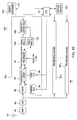
- FIG. 1 depicts a block diagram of a global navigation satellite (GNSS) receiver 100 incorporating the present invention.
- GNSS global navigation satellite
- the use of a GNSS receiver as the platform within which the invention is incorporated forms one application of the invention. Other platforms that require signal correlation may find use for the present invention.
- the GNSS receiver may be adapted to receive global positioning system (GPS), GLONASS, GALILEO and the like signals.
- GPS global positioning system
- GLONASS global positioning system
- GALILEO global positioning system
- the following disclosure uses GPS and GPS signals as an example of the type of signals to be processed by embodiments of the invention.
- a radiofrequency-to-intermediate-frequency converter (RF/IF converter) 102 filters, amplifies, and frequency shifts the signal for digitization by an analog-to-digital converter (A/D) 103.
- RF/IF converter radiofrequency-to-intermediate-frequency converter
- A/D analog-to-digital converter
- the elements 101, 102 and 103 are substantially similar to those elements used in a conventional GPS receiver.
- the output of the A/D 103 is coupled to a set of processing channels 104 1 , 104 2 , ...104 n (where n is an integer) implemented in digital logic.
- Each processing channel 104 n may be used to process the signal from a particular GPS satellite.
- the signal in a particular channel is tuned digitally by a tuner 105, driven by a numerically controlled oscillator (NCO) 106.
- the tuner 105 serves two purposes. First, the IF frequency component remaining after RF/IF conversion is removed. Second, the satellite Doppler frequency shift resulting from satellite motion, user motion, and reference frequency errors is removed.
- the output from the tuner is a baseband signal consisting of an in-phase component (I) and a quadrature component (Q).
- the steps of 105 and 106 are substantially similar to those used in conventional GPS receiver designs.
- a decimation circuit 107 processes the output of the 105.
- the output of the decimation circuit 107 is a series of complex signal samples with I and Q components, output at a rate precisely timed to match the timing of the input signal.
- the decimation operation is a simple pre-summer that sums all the incoming signal samples over the period of an output sample.
- the NCO adjusts for Doppler shift based on external input from firmware commands. Because the Doppler shift is different for each satellite, a separate code NCO 108 and decimation circuit 107 is required for each channel 104 n . It should be noted that there is no requirement that the incoming sample rate be an integer multiple of the f s , as the code NCO 108 is capable of generating an arbitrary frequency. If the decimation circuit 107 is a pre-summer, the number of samples summed will typically toggle between two values, so that over the long term, the correct sample timing is maintained. For example, if the incoming sample rate is 10 MHz, and the desired sample rate is 2.046 MHz, the pre-summer will add either 4 or 5 samples, so that the desired sample rate is maintained on average.
- the decimation circuit 107 may also include a quantizer (not shown) at its output to reduce the number of bits in the signal components before further processing.
- a quantizer (not shown) at its output to reduce the number of bits in the signal components before further processing.
- 2-bit quantization is used.
- the signal samples from decimation circuit 107 are coupled to a convolution processor 109.
- the convolution processor 109 generates results that are stored in signal random access memories (RAMs) 110a and 110b.
- RAMs 110a and 110b hold a complex vector that makes up all or part of the full convolution between the input signal and a reference PN code (e.g. a GPS C/A code).
- the convolution result will have a peak at points corresponding to high correlation between the signal and reference (the PN code). As shall be discussed in detail below, the relative location of these peaks for various satellite signals is used to ultimately compute position information.
- the convolution processor 109 and signal RAMs 110a and 110b accumulate convolution results for multiple epochs of the GPS signal, which repeats at nominal 1 millisecond intervals. For example, if 10 milliseconds of the signal are processed, the values in RAM 110a and 110b are the sum of 10 correlation results each generated over one epoch. All the individual correlations should have a similar characteristic, since the timing of the decimation operation ensures that samples are taken at the same relative moment within each epoch. Accumulating similar results from individual correlations improves the signal to noise ratio, enhancing the ability of the receiver to detect weak signals.
- This processing may be referred to as coherent integration and, as will be discussed, can be combined with magnitude integration to yield correlation results averaged over a time period of up to several seconds.
- the length of time over which coherent integration interval is performed is limited by several factors, including uncompensated Doppler shift, GPS signal navigation data bits, and phase shifts induced by motion of the receiver 100. These factors introduce slow, but seemingly random phase variations into the signals. Over many tens of milliseconds, these phase changes cause destructive interference that defeats the purpose of coherent integration. Therefore, to achieve long averaging intervals, the receiver 100 performs a secondary step of magnitude accumulation. Specifically, the signals stored in the signal RAMs 110a and 110b are periodically output to a complex normalizer 111 that generates a complex magnitude value of the complex convolution vector. The complex magnitude values are accumulated by an adder 112 and stored in magnitude RAM 113.
- the signal RAMs 110a and 110b are cleared to allow another coherent integration to occur. The process continues until the desired number of magnitude accumulations is completed. For example, if the coherent averaging interval is 10 milliseconds, and 200 magnitude accumulations are desired, the total process will run over 2 seconds.
- the magnitude RAM 113 contains a vector containing the complex magnitude of the convolution result, integrated to improve signal-to-noise ratio. As shall be discussed below, this vector is further processed by software algorithms that are executed by the CPU 114 to produce pseudorange data that is used to yield the position of the receiver. It should be noted that the CPU computational load for these steps is quite modest compared to a conventional GPS receiver or an FFT based correlator. In this implementation, the computationally intensive tasks of correlation and integration are completed prior to software processing.
- FIG. 2 depicts waveforms 201I, 201 Q and 202 generated by the components of FIG. 1 .
- the waveforms 201I, 201 Q and 202 are plots of signal strength (axis 208) versus code chips (axis 210).
- Waveforms 201I and 201 Q are the output from the convolution processor 109 where 201I is the I- component of the output and 201Q is the Q- component.
- Each block of 2046 samples is a full convolution result, generated in real time by the convolution processor 109 from the 2046 signal samples processed during the interval.
- the convolution result contains noise except in the vicinity of a single peak (such as indicated by reference numbers 2061 and 206Q) corresponding to the time delay of the signal.
- the signal repeats every epoch, so the peak reappears each 2046 samples.
- correlation results are accumulated in the RAM 110a and 110b by summing values at corresponding delays from each epoch. (For example, the values at output time 4 are summed with the values at output time 2050 and 4096.)
- the correlation peak always appears at the same delay offset and the size of the peak increases over the accumulation, roughly tripling over 3 epochs.
- Waveform 201Q illustrates the same signal accumulation process occurring in the quadrature channel.
- Waveforms 201I and 201Q show the correlations accumulating and dumping 3 times over 9 signal epochs.
- the accumulated signal's magnitude is computed and summed into the magnitude RAM113.
- the signal in the magnitude RAM 113 is shown as waveform 202.
- the waveform 202 updates three times corresponding to the completion of each coherent integration.
- the peaks are identified by reference numbers 212 1 , 212 2 , 212 3 and noise is identified by reference number 214.
- the signal-to-noise ratio increases with each magnitude accumulation, further enhancing the ability of the system to identify the peak corresponding to the time of arrival.
- the complex phase of the signal varied over the 9 epochs.
- the signal was initially present in both I and Q channels, but by the final epoch, had rotated so that the signal was strong in the I channel and nearly absent in the Q channel.
- imperfect Doppler shift tuning and other effects cause this rotation.
- the phase would rotate through many cycles, resulting in cancellation of the signal when accumulated.
- the inventive receiver accumulates coherently over only a short interval, relying on magnitude (non-coherent) accumulation for long term averaging. Magnitude values are independent of phase, and may be successfully integrated over several seconds.
- FIG. 3 illustrates the accumulated magnitude waveform 202 in greater detail.
- the plot 300 shows the magnitude of the convolution in the vicinity of a peak 212 3 corresponding to the time delay of the signal.
- the convolution results are further processed, typically in the CPU 114, to produce the position information.
- One embodiment uses a least squares estimation technique to identify parameters of a signal that best fits the noisy measured data.
- the ideal response of a signal is the magnitude of the autocorrelation of the signal.
- This waveform can easily be shown to have the form of a raised triangle 302.
- the height 304 of the base of the triangle is the magnitude of the noise in the convolution for time delays not corresponding to the signal.
- FIG. 4 depicts a detailed block diagram of the convolution processor 109 (as well as the convolution results processing circuits 400), in particular details showing how a full convolution is generated by repeated use of a small block of circuitry. Operation of the circuits can be best understood with simultaneous reference to FIG. 4 , a flow diagram of FIG. 5 representing the operation of the processor 109 of FIG. 4 , and by comparison of the simple examples of FIG. 6 and FIG. 7 .
- Signals advance through shift registers 401 a and 401 b at the rate of 2f o , as timed by the code NCO 108.
- Each partial correlation consists of a fast vector multiply and add operation between the contents of each signal shift register and a segment of the code containing P x K (e.g., 66) code samples.
- the fast vector multiplication and addition occurs in circuits 402a and 402b.
- Circuits 402a and 402b respectively comprise multipliers 410a and 410b and summers 412a and 412b.
- the operation consists of multiplying each of the 66 signal samples in the signal register 401 a or 401 b by 66 code samples (formed by extending 33 code samples with the code extender 409), and summing the results in summer 412a and 412b.
- the operation occurs separately and simultaneously in the I and Q channels.
- the output of the vector multiply and add may be re-quantized to keep the numbers in a small range so as to avoid overflowing RAMs 404a and 404b.
- the quantizer is not shown.
- the re-quantization is to 2 bits of resolution.
- circuits 400 comprise signal RAM 110a, 11 0b, complex normalizer 111, adder 112 and magnitude RAM 113. stored in signal RAMs 111a and 404b.
- the accumulation process consists of reading from RAM 110a and 110b the current values for a particular time delay, adding the just computed partial correlations, and writing the sums back to RAMs 110a and 110b. By properly combining partial correlations that correspond to a particular time delay, the full correlation for that delay is computed. As described previously, the process continues for as many epochs of the signal as desired to enhance signal to noise ratio.
- the adders 403a and 403b serve two purposes: the combining of partial correlations within an epoch; and the accumulation of correlations across several epochs.
- the outputs from signal RAMs 110a and 110b are combined in complex normalizer 405 to form the magnitude of the signal.
- the I and Q waveforms in these RAMs 110a and 110b can be viewed as the real and imaginary part of a complex waveform.
- Forming the magnitude consists of squaring each component, summing the results, and taking the square root of the result.
- the complex magnitude is approximated by taking the scalar magnitude of I and Q independently and determining which is larger.
- the magnitude can be approximated by taking the larger magnitude and adding it to the one half of the smaller magnitude.
- the results of the magnitude operation may be scaled to keep the values in a small range so as to avoid overflowing RAM 113.
- a scalar is not shown.
- the scaling consists of shifting the result by 3 bits (i.e., divide by 8).
- the operation in 405 would be power estimation, typically computed by taking the sum of the squares of I and Q.
- the pseudorange determination algorithms described in reference to FIG. 3 would have to be slightly modified to perform a fit against a power waveform as opposed to a magnitude waveform.
- additional nonlinear operations could be used to generate values representative of the magnitude or power of I and Q.
- the output from complex normalizer 111 is accumulated by the adder 112 into magnitude RAM 113.
- the accumulation process consists of reading from RAM 113 the current magnitude value for a particular time delay, adding in the just computed magnitude result, and writing the sum back to the RAM 113. As discussed previously, the magnitude accumulation continues for as many cycles as required to achieve signal to noise ratio enhancement.
- the vector multipliers 402a and 402b perform M partial correlations for each shift of the signal.
- a code lookup circuit 408 generates the reference code samples for each partial correlation. The lookup is controlled by two lookup indexes. First, the code must be selected from 1 of 32 codes. This selection is constant through the convolution process and is established when the processing channel is configured to correlate for a particular satellite signal. The second index is a segment index between 1 and M. Each C/A code consists of 1023 chips, which are divided into M non-overlapping segments each consisting of K adjacent code chips. The lookup index identifies which code segment is needed. The output from the code lookup circuit is K chips comprising the segment. The selection process is controlled by Control/Address Logic 414.
- the code extender 409 takes as its input K chips of a segment and extends the segment into K x P code samples.
- the extension operation consists of converting each code chip into P identical code samples.
- the output from the code extender 409 forms the reference code input to vector multipliers 402a-b.
- the output from the code extender is 66 samples made up of 33 unique values, each replicated twice.
- the architecture shown in FIG. 4 requires a clock that is substantially faster than the C/A code rate f o .
- P 2 samples per C/A code chip
- K and M are to be 33 and 31 respectively
- achieving the full convolution requires performing 31 partial correlations for each shift of the signal shift register, which advances at rate 2 x f o .
- at least two clock cycles are required to read and write RAMs 110a and 110b.
- the invention could also be used to compute a subset of the full convolution.
- fewer than M partial correlations are performed for each shift of the signal shift register.
- the total range of delays will be less than the P x 1023 making up a full convolution.
- M 2 partial correlations are performed, then M 2 times K times P delay values are generated.
- the clocking rate to the processor is reduced by the ratio of M 2 to M.
- the size of the RAMs is reduced by this ratio as well.
- K and M result allows further design tradeoffs to be made, however, since the prime factors of 1023 are 3, 11, and 31, the choices for K and M are limited. Reducing K is desirable since this reduces the size of the shift registers 401 a and 401 b and the complexity of the vector multipliers 402a and 402b, but requires a larger M and therefore a large clocking rate.
- control logic 414 This control logic also identifies the correct addresses for the RAMs 110a, 110b and 113. As will be discussed below, the partial correlations are generated in a non-sequential order, thus the generation of RAM addresses is non-trivial.
- Operation begins at step 501 with pre-loading of the signal shift registers 401 a and 401 b. At this point, convolution processing can begin.
- a code segment is accessed for the particular partial correlation.
- the code segment is extended by the code extender to have P samples per C/A chip.
- the delay index and corresponding RAM addresses are computed.
- the delay index indicates which point of the full convolution will be updated by the partial correlation. As will be apparent from the example discussed in conjunction with FIG. 7 , the delay index jumps around in a non-linear, but deterministic manner.
- the address computation is a function of the number of signal shifts and the code segment.
- step 505 the partial correlation is computed using the vector multipliers 402a and 402b.
- step 506 the result is accumulated into the signal RAMs at the location indicated by the delay index.
- step 507 a check is made to determine whether the processing has reached the end of the coherent integration interval. If not, the method returns back to step 502a, and repeats for the above steps for the next code segment.
- step 507 If, at step 507, the check indicates that partial correlations are complete for all code segments (e.g., 31 partial correlations), the method proceeds to step 508.
- step 508 the signal registers 401 a and 401 b are shifted by one sample.
- step 509 a check is performed to see if the last shift encountered the end of the coherent integration interval. If not, the process cycles back to the start at step 502. If the check indicates the end of the coherent integration interval, then the method continues to step 510, where the signal magnitude is computed by complex normalizer 111. The result is added using adder 112 and stored in the magnitude RAM 113. Next, at step 511, a check is made to determine if all magnitude accumulations have been performed. If so, the method completes at step 512. If not, processing continues by performing the next partial correlation at step 501.
- FIG. 6 and FIG. 7 illustrate, through a simplified example, how the invention utilizes partial correlations to accumulate a full convolution result.
- these diagrams illustrate convolution of a very short length 6 code, as opposed to the length 1023 C/A code of a GPS signal.
- P one sample per code chip
- FIG. 6 illustrates convolution through a standard matched filtering approach
- FIG. 7 illustrates the identical convolution through the method of combining of partial correlations. The details of FIG. 7 are helpful in understanding overall operation of the invention. Both methods generate identical convolution results.
- FIG. 6 shows the operation of a conventional matched filter for a length 6 signal. Operation begins at a moment in time indicated as shift 0. At this moment, 6 consecutive signal samples comprising an entire cycle of the signal are in the signal shift register 601. Individual samples are labeled with uppercase indices A, B, C, D, E, and F. Code samples for the entire length 6 code are held in reference register 602 and are labeled with lowercase indices a, b, c, d, e, and f. At the time of shift 0, a vector multiplication and add is performed to generate the correlation result for shift 0. Each signal sample is multiplied by a corresponding code sample and the results are summed to yield correlation result 603.
- the signal shift register 604 is advanced by one sample, as indicated by shift 1.
- the signal is periodic, so the new sample introduced at the left side of the register is identical to that shifted out to the right.
- the shifted contents of the register 604 are now samples with indices F, A, B, C, D, and E.
- the code is not shifted.
- the vector multiplication and addition now yields a correlation result 605 for shift 1. This process of shifting continues for 5 additional shifts, at which point all 6 correlation results making up the full convolution are available.
- FIG. 7 illustrates how the same convolution result can be obtained through the method of partial correlations.
- the invention requires that the code be factored into M segments of length K.
- the first code segment 702 contains 2 code samples labeled with lowercase indices a and b.
- the signal is held in place for 3 partial correlation operations, resulting in partial correlation results 703a, 703b and 703c.
- the first partial correlation result is created by a vector multiplication and addition between the contents of the signal register and the first code segment (segment 1).
- the second and third results are created by vector multiplications of the signal register with the second and third code segments respectively. Note that the signal register is held in place for a sufficient time for all three-vector multiplications to be performed, and that the code is not shifted during this time, rather different code segments are selected.
- the partial correlation results are accumulated into the memory according to the signal paths 705. For example, at shift 0, the partial correlation from the first code segment sums into the correlation result 704. The partial correlation from the second segment sums into the correlation result 706 for shift 2. The partial correlation from the third segment contributes to the correlation result 708 for shift 4.
- the signal is shifted.
- the signal register contains samples F and A.
- three partial correlations are generated with the same three code segments as before.
- the results from these partial correlations contribute to correlation results 710, 712, 714 respectively for shifts 1, 3, and 5.
- the process continues for 4 additional signal shifts, at which time the full convolution result is available. As can be seen, the operation requires generating a total of 18 partial correlations that contribute to the 6 full results comprising the convolution.
- FIG. 7 illustrates two important properties of the invention.
- Second, in FIG. 7 the code samples are accessed in fixed segments that are the same for each shift, and each segment is a separate non-overlapping section of the code.
- a simple lookup or register scheme can be used to provide the code to the vector multipliers, as will be discussed further in reference to FIG. 8 and FIG. 9 .
- These schemes require less circuitry than other architectures that might, for example, require large blocks of code bits to be made available in a more complex set of permutations.
- the invention also eliminates the need to provide code generation circuitry.
- FIG. 8 shows a block diagram of one embodiment of a code lookup circuit 408 suitable for the invention.
- Table 801 contains stored values for all 1023 bits of each of 32 codes, for example in read-only memory (ROM) or hard-wired logic.
- Multiplexer 802 selects a particular code based on a select value.
- the output of multiplexer 802 is a particular sub-table for the desired .
- Multiplexer 803 selects a particular segment based on a segment select value between 1 and M.
- the output of 803 is a particular code segment 804, of length K, which contains code bits provided to code extender 409.
- multiplexer 803 must be high speed in order to allow the code segment to be changed each partial correlation, i.e. every two clock cycles. For this reason, it is necessary that all code bits be pre-stored in table 801, as opposed to being generated on the fly in the traditional manner of a code generator.
- circuits of FIG. 8 are intended to be illustrative. In practice, there are many different circuit designs that are functionally equivalent. In particular, the process of logic synthesis used in modern ASIC design will lead to a certain pattern of gates that achieves a behavior equivalent to that described above but not necessarily using multiplexers in the manner described.
- FIG. 9 shows a block diagram of an alternate embodiment of a code lookup circuit 408 suitable for the invention.
- the 1023 code bits corresponding to a particular code are held in 1023 dual-directional shift registers 901, organized as M rows of length K.
- the shift registers operate in two modes: a running mode, and a loading mode.
- each register 901 is configured to shift its sample to the register above it in the next row, except for the top row of registers that shifts to the bottom row of registers.
- the shift directions for running mode are indicated by solid arrows within 901.
- each register In the loading mode, each register is configured to shift its sample to the register next in its row, except for the last column of registers, which shift to the first column of registers in the row above.
- the shift directions for loading mode are indicated by dotted arrows within 901.
- the left hand lower shift register 904 is connected to code generator 902.
- the code generator is a traditional code generator, capable of sequentially creating the 1023 code bits of a particular code based on a select value.
- the code lookup circuit When the code lookup circuit is configured for a particular, the registers are placed in the loading mode, and the generator is used to generate the bits of the code, which then clock through the registers. After all bits have been clocked through, the code will reside in the registers as M segments of length K. The circuit is then ready for use in the running mode.
- Fig. 10 depicts a block diagram of another embodiment of a GPS receiver 1000.
- the receiver 1000 comprises a plurality of processing channels 104 that operate in a correlation history mode as well as a standard correlation mode.
- the function of the standard correlation mode is as described above with respect to FIGS. 1-9 .
- Operation of the components of the receiver 1000 in the correlation history mode is substantially identical to the standard mode for all blocks leading up to the signal RAMs 110a and 110b and magnitude/history RAM 1002.
- the CPU 114 is shown in FIG. 10 as being supported in a conventional manner by a memory 1010 and support circuits 1012.
- the support circuits 1012 comprise such well-known support circuits as clocks, buses, cache, power supplies, I/O circuits, and the like.
- the memory 1010 may comprise one or more of random access memory, read only memory, removable memory, and the like.
- the memory 1010 forms a computer readable medium for storing software 1014 that, when executed by CPU 114, causes the receiver 1000 to operates in accordance with the methods describe below.
- the combination of the CPU 114, the memory, and the support circuits forms a processing unit 1016.
- the signal RAM's 110a and 110b are used to accumulate partial correlation results over a coherent averaging interval for all of the correlation delays comprising a full convolution.
- the correlation history mode uses only a small subset of these results that correspond to delays in the vicinity of a correlation peak.
- programming parameters establish a small number of delays of interest. For these delays, a complete history of all coherent averaging results is stored in magnitude/history RAM 1002. There is no magnitude accumulation performed in the convolution processor during the correlation history mode.
- the RAM 1002 is used as a memory for storing the correlation history (history memory) during the correlation history mode and a memory for magnitude (magnitude memory) during the standard operation of the convolution processor 109.
- Another programming parameter defines how many consecutive coherent accumulation results to store in RAM 1002.
- the convolution processor 109 fills the magnitude/history RAM with a two dimensional table of results indexed by delay and epoch (See Fig. 11 ).
- the number of epochs that can be stored is set by the RAM size and the number of selected delays. For example, if the RAM is sized for 2048 words, the memory could be used either to store 2048 cycles for a single delay, 1024 cycles for 2 delays, or 512 cycles for 4 delays and so forth.
- a word width of 12 bits allows I and Q portions of the coherent averaging result to be stored individually with 6 bit resolution.
- Fig. 12 shows a graphical example 1200 of a typical correlation history.
- the upper and lower graphs 1202 and 1204 show the I component and Q component waveforms respectively.
- Each point in the graphs represents a single coherent integration.
- the coherent integration interval was set to 1 epoch so each point represents nominally one millisecond of integration.
- the waveforms of Fig. 12 illustrate two aspects of the signal after correlation.
- the correlation history mode is invoked to determine satellite signal Doppler and/or navigation bit timing in order to estimate certain receiver parameters such as oscillator frequency and receiver clock timing. Initially, the mode provides data used by software algorithms to estimate residual Doppler and the timing of the navigation data bits relative to the start of the correlation history. Subsequently, as necessary, the mode is also used to provide a history for decoding of the values of the navigation data bits.
- a software algorithm determines Doppler and bit timing, for one or more satellites in order to generate or update a GPS receiver's estimate of its own oscillator frequency and/or internal clock timing.
- more precise correlations are performed by using the oscillator frequency and clock timing estimate to "correct" the carrier and code NCO's 106 and 108 of FIG. 10 and to adjust the timing of convolution processor 109.
- an improved estimate of the receiver oscillator frequency allows the correlation processor 109 to be more precisely tuned via NCO 105, providing better signal detection and the ability to utilize longer coherent integration intervals.
- an improved estimate of the receiver clock timing can be used to control the start times of the convolution processor 109 so as to perform coherent integrations that are synchronous with the navigation data bit timing for each satellite, improving signal detection.
- Prior art techniques use a register bank to store correlator output for a tracking process in which PN epochs and carrier of a satellite signal are tracked.
- the tracking process requires a high signal to noise ratio.
- the correlation history mode of the current invention does not merely buffer data for the purpose of tracking a particular satellite signal. Rather, the correlation history mode is used to estimate receiver parameters that aid in the detection of all satellites in view. Furthermore, the correlation history mode operates in conjunction with a software estimation algorithm that extracts satellite signal information even at very low signal to noise ratios that would fall below the threshold of a conventional tracking process. Correlation history mode processing of signals from multiple satellites may be used to enhance performance of the receiver parameter estimation, but such additional signals are not necessary to practice the invention.
- the process 1300 is embodied in a software program that performs a sequence of steps that performs a particular function.
- the process 1300 is performed to determine an estimate of signal magnitude (magnitude estimate) at a particular frequency and bit timing hypothesis, and the estimate is optimized over a range of possible frequencies and bit timings.
- the I and Q correlation history is first phase corrected (step 1302) by performing a multiplication with a complex frequency term corresponding to the conjugate of the frequency modulation.
- the signal is integrated over a coherent integration spanning up to a navigation bit period.
- a magnitude computation operation is performed to form a power value.
- the results from successive magnitude computations are then further summed, at step 1308, to improve signal to noise ratio.
- one second of data provides 50 bit periods that can be summed to form an integrated power for the bit periods used in the summation.
- the computations can be performed to determine a signal level, e.g., signal magnitude or signal power.
- the embodiment of the invention described herein uses signal magnitude; however, those skilled in the art will realize that signal power or any other measure of signal level can be used to implement this invention.
- the power estimates are collected over a range of possible frequencies and bit timing values.
- the results can be viewed on a two dimensional grid 1400 as illustrated in FIG. 14 .
- One axis 1402 is the hypothesized frequency error, in this case varying from -40 to 80 Hz.
- the other axis 1404 is the bit-timing hypothesis, varying between 0 and 19 epochs. This value represents the hypothesized offset between the bit timing and the beginning of the correlation history that was taken at a particular time according to the receiver clock.
- the vertical axis 1406 at each point in the grid is the correlated signal magnitude corresponding to the Doppler and timing hypothesis.
- the best estimate of frequency and timing corresponds to the maximum point 1408 on the grid. This minimizes the signal-to-noise ratio (SNR) loss that can occur if the coherent averaging interval is misaligned with the data bits.
- SNR signal-to-noise ratio
- FIG. 15 shows a graph 1500 of a cross section of FIG. 14 along the frequency axis 1402. As can be seen, the response peaks (point 1502) at the correct frequency. Similarly FIG. 16 shows a graph 1600 of a cross section of FIG. 14 along the bit timing hypothesis axis 1404. Again, the largest magnitude is seen at the peak of the triangle (point 1602) corresponding to the correct bit timing.
- the process described herein provides a two-dimensional set of points over which the maximum can be searched.
- a course estimate of frequency could be performed at an arbitrary bit timing to obtain a frequency close to the peak of the surface.
- the analysis with arbitrary bit timing is followed by an estimate of the response at that frequency at all bit timings (and preferably with a coherent averaging interval of 20 epochs) to allow bit timing to be estimated. If desired, this could be followed with an additional estimate of frequency.
- a sequential estimation algorithm could be implemented in software.
- a frequency discriminator forms an estimate of the frequency error.
- the frequency error is applied and the discriminator provides another improved estimate of frequency error. The process continues until the residual frequency error is small.
- the algorithm operates entirely on the stored correlation history without applying feedback to NCO 106 and without performing additional correlations. Once the frequency is estimated, bit transitions can be identified from the timing of the 180° phase transitions. Since the frequency error has largely been removed, the phase transitions are readily observable.
- FIG. 17 illustrates a method 1700 of using the correlation history mode in relationship to the operation of a GPS receiver.
- correlations are performed in the standard mode, scanning for signals across a range of delays and searching in frequency as necessary.
- the signal from one or more satellites are selected for correlation history mode processing.
- a processing channel or several channels of the receiver are reconfigured for correlation history mode, and correlation histories are accumulated. Normally, the correlation history need only be accumulated at a single delay, since an estimate of delay is available from the initial signal acquisition.
- the correlation history or histories are processed as described above to yield estimates of the signal frequency and bit timing for each channel operated in correlation history mode.
- these estimates are then combined with a satellite range and range rate models to determine information used to update the receiver's model of oscillator frequency and clock timing. These estimates are then used together with satellite range and range rate models for all satellites to compute the expected bit timing and Doppler of up to all satellites in view and to calculate improved programming values for NCO 106 and 108 and to set the coherent integration start timing of convolution processor 109.
- the receiver then switches to a standard mode of operation to correlate signals from all the satellites in view of the receiver as described with respect to FIGS. 1-9 .
- the receiver uses the improved frequency and clock timing estimates to perform standard correlation on the GPS signals. The foregoing process is repeated, as necessary, to perfect the receiver parameter estimates.
- the frequency determined in correlation history mode for a particular satellite can be compared to the expected range rate for that satellite to determine a difference value that can be attributed to an error in the frequency of the receiver clock, based on the stationary receiver model.
- the errors can be used to estimate the receiver clock frequency and the receiver velocity as well.
- the estimated receiver oscillator frequency can be combined with the expected range rate for any satellite to determine an improved tuning frequency for NCO 106 for detecting the satellite.
- an estimate of the receiver timing error can be generated from the bit timing measurements.
- the signal histories are captured at a particular reference time relative to the receiver's internal clock.
- this clock is a millisecond counter.
- the timing of this counter is in general arbitrary relative to GPS time.
- a time relationship can be established between the millisecond counter and GPS time. To explain this, it is relevant to point out that, data bits leave all satellites synchronously. At the bit transitions, the modulo 20 value of GPS time is zero. Signals from these satellites arrive at the receiver many milliseconds later. The delay between the time of transition and time of reception may be easily determined from an estimate of the receiver position, rough time, and satellite orbit information.
- the absolute timing of data bit transitions at the receiver can be estimated, in terms of GPS time. Once the timing of these same transactions is measured relative to the receiver millisecond clock, a relationship can be established between the receiver clock and GPS time. It should be noted that this is not an absolute relationship, because only the navigation data bit transitions have been established not the timing of navigation data bit frame. Rather, the modulo 20 millisecond value of the receiver clock can be related to the modulo 20 millisecond value of GPS time.
- the receiver To align subsequent coherent integration intervals, the receiver first estimates the timing of the navigation data bit for each satellite relative to GPS time (based on the pseudo range). Correlations performed by convolution processor 109 are programmed to begin at some convenient future time based on the receiver millisecond clock. The modulo 20 millisecond value of this start time is chosen relative to GPS time and the timing of the navigation data bits to ensure alignment of the coherent integrations with the data bits.
- the correlation history mode can also be used to collect navigation data bits. Normally, this mode is invoked after navigation data bit timing has been established.
- the correlation processor is programmed for coherent integration intervals of 20 epochs, with intervals aligned with the data bits, and a correlation history is stored. Each point of the correlation history is the result of integration over a full bit period. The presence or absence of a phase transition from one bit to the next provides the information data bit.
- the correlation history can be used to store bits up to the size of the RAM. If more bits are required, multiple correlations histories can be stored in succession.
- FIG. 18 is a block diagram depicting another embodiment of a GPS receiver 1800 coupled to an external processing unit 1801.
- the GPS receiver 1800 may be embedded within a mobile device 1899, such as a cellular telephone, which includes the external processing unit 1801.
- Elements of FIG. 18 that are the same or similar to elements of FIGs. 1 and 10 are designated with identical reference numerals and are described in detail above.
- the GPS receiver 1800 may include a plurality of processing channels 104. For purposes of clarity, only a single processing channel 1041 is shown. Those skilled in the art will appreciate, however, that multiple processing channels 104 may be used. Each of the processing channels 104 is capable of operating in both the correlation history mode and the standard correlation mode as described above with respect to FIGs. 1-17 .
- the GPS receiver 1800 comprises a co-processor 1804 and receiver interface logic 1802, each of which is coupled to the processing channel 104 1 .
- the CPU 114, the memory 1010, and the support circuits 1012 form the external processing unit 1801.
- the external processing unit 1801 may be located in the mobile device 1899 and may cooperate with various other mobile device circuits 1805, such as cellular telephone circuitry.
- the co-processor 1804 includes a bus coupled to the receiver interface logic 1802.
- the receiver interface logic 1802 is coupled to an external bus 1803 of the CPU 114.
- the receiver interface logic 1802 facilitates communication between the GPS receiver 1800 and the external processing unit 1801.
- the co-processor 1804 is further coupled to a memory 1810.
- the memory 1810 stores software 1812, which may be executed by the co-processor 1804 to analyze correlation results stored by the GPS receiver 1800 and derive satellite signal parameters therefrom.
- the processing channel 104 1 comprises a channel interface 1806 and channel control logic 1808.
- the channel interface 1806 is coupled to a bus of the co-processor 1804.
- the channel interface 1806 may be further coupled to the receiver interface logic 1802.
- the channel interface 1806 includes a bus coupled to the magnitude/history RAM 1002 and a bus coupled to the channel control logic 1808.
- the channel interface 1806 facilitates communication between the co-processor 1804, the receiver interface logic 1802, and the processing channel 104 1 .
- the channel control logic 1808 is coupled to provide control signals to the carrier NCO 106, the code NCO 108, and the convolution processor 109.
- the control signals may be used to adjust the frequency of the carrier NCO 106 and the code NCO 108, as well as the operational mode and timing of the convolution processor 109. If the GPS receiver 1800 includes multiple processing channels 104, the channel interface 1806 of each processing channel 104 is coupled to the co-processor 1804 and may be coupled to the receiver interface logic 1802.
- the CPU 114 executes control software 1850 stored in the memory 1010 to provide commands to the GPS receiver 1800 to obtain one or more satellite signal parameters. Exemplary satellite signal parameters are described below with respect to FIG. 19 .
- Each command includes programming parameters for configuring the GPS receiver 1800 such that the desired satellite signal parameters may be obtained. Such programming parameters include the frequency of the carrier NCO 106, the frequency of the code NCO 108, and the timing and operation of the convolution processor 109 for one or more of the processing channels 104.
- the GPS receiver 1800 may process satellite signals in either the standard mode of operation or in the correlation history mode. In either mode, the GPS receiver 1800 operates to produce correlation results, which are stored within the magnitude/history RAM 1002.
- the correlation results stored within the magnitude/history RAM 1002 are not analyzed using the CPU 114 of the external processing unit 1801. Rather, the co-processor 1804 analyzes the correlation results in accordance with the command issued by the CPU 114 to provide desired satellite signal parameter(s). After analyzing the correlation results, the co-processor 1804 provides the satellite signal parameter(s) produced by the analysis to the CPU 114 using the receiver interface logic 1802. Given the satellite signal parameter(s), the CPU 114 may then determine one or more receiver parameters using the satellite signal parameters. As described above, such receiver parameters include oscillator frequency and receiver clock timing.
- the present invention provides for a faster analysis of the correlation results and does not burden the CPU 114 of external processing circuits 1801.
- the present invention obviates the need to provide all the correlation results stored within the magnitude/history RAM 1002 to the CPU 114 for analysis.
- only a small amount of data comprising the desired satellite signal parameter(s) is sent to the CPU 114.
- the receiver interface logic 1802 and bus 1803 comprise a serial interface.
- FIG. 19 is a flow diagram depicting an exemplary embodiment of a satellite signal parameter estimation process 1900 in accordance with the invention.
- a GPS receiver includes a co-processor and is coupled to an external processor, as described above with respect to FIG. 18 .
- the process 1900 begins at step 1902, where a command is issued from the external processor to the GPS receiver to obtain one or more satellite signal parameters.
- one or more channels within the GPS receiver are configured in accordance with programming parameters associated with the command.
- satellite signals are processed using the configured channels and correlation results are stored within memory.
- the co-processor analyzes the correlation results to produce the requested satellite signal parameters.
- the requested satellite signal parameters are provided to the external processor.
- the satellite signal parameters may be used to produce one or more receiver parameters, which in turn may be used to configure the GPS receiver.
- FIG. 20 is a block diagram depicting an exemplary embodiment of the co-processor 1804.
- the co-processor 1804 illustratively comprises a bus 2001 coupled to an I/O interface 2002, a memory 2004, a complex modulator 2008, support circuits 2010, a complex power unit 2012, a complex cross-product unit 2014, a complex dot-product unit 2016, a coherent integration unit 2018, a non-coherent integration unit 2020, and a noise statistics unit 2022.
- the I/O interface 2002 is configured to receive I and Q correlation results from a processing channel of the GPS receiver, as well as command and configuration data from the external processing unit.
- the I/Q correlation results may be stored within a buffer 2006 of the memory 2004.
- the command and configuration data is used to control the components of the co-processor.
- the complex modulator 2008 may be used to frequency tune the I/Q correlation results to compensate for Doppler.
- the complex power unit 2012 may be used to compute the average power of a given I/Q correlation sample.
- the complex cross-product unit 2014 may be used to compute a complex cross-product between a first I/Q correlation result and a second I/Q correlation result.
- the complex dot-product unit 2016 may be used to compute a complex dot-product between a first I/Q correlation result and a second I/Q correlation result.
- the coherent integration unit 2018 may be used to pre-sum a plurality of I/Q correlation results.
- the non-coherent integration unit 2020 may be used to sum a plurality of magnitude results computed using I/Q correlation results.
- the noise statistics unit 2022 may be used to compute various noise statistics (e.g., mean and sigma of the I/Q correlation results).
- the support circuits 2010 comprise buffers, registers, quantizers, counters, and the like-type logic circuits for supporting operation of the co-processor 1804 and the components discussed above.
- Exemplary embodiments of the process 1900 may understood with reference to FIGs. 18 and 20 . Notably, the process 1900 may be repeated as desired for various commands issued by the CPU 114. Such commands include, for example, requests for a range measurement, a high-resolution range measurement, a Doppler measurement, navigation data measurement, or a bit timing measurement.
- commands include, for example, requests for a range measurement, a high-resolution range measurement, a Doppler measurement, navigation data measurement, or a bit timing measurement.
- the CPU 114 issues a command to request one or more satellite signal parameters
- the GPS receiver 1800 computes the requested satellite signal parameters using the co-processor 1804, and the GPS receiver 1800 returns the requested satellite signal parameters to the CPU 114.
- the CPU 114 may send a range measurement command to the GPS receiver 1800.
- the convolution processor 109 operates in the standard mode and computes a plurality of correlation results as described above.
- the range measurement command specifies a range of relative delays between a satellite signal and the reference C/A code to examine.
- the co-processor 1804 locates the point of maximum correlation response (i.e., correlation peak) and returns delay measurements for a range around the peak.
- the co-processor 1804 may also analyze the correlation results using the noise statistics unit 2022 to determine various noise statistics, such as the mean and sigma of the correlation response. These noise statistics may be used to determine the signal-to-noise ratio of the correlation peak.
- the delay measurements as well as the noise statistics may then be provided to the CPU 114.
- the CPU 114 may send a Doppler measurement command to the GPS receiver 1800.
- the correlation response for one or more relative code delays between the satellite signal and the C/A reference code is stored as a correlation history in the magnitude/history RAM 1002.
- the correlation history includes I and Q samples for each coherent summing interval of the convolution processor 109.
- the coherent summing intervals within the convolution processor 109 may vary from 1 to 10 epochs.
- the co-processor 1804 retrieves the I and Q correlation results stored in the magnitude history RAM 1002 that comprise the correlation history.
- the co-processor 1804 analyzes frequency by tracking the phase changes from sample to sample.
- the frequency may be found by averaging the complex cross product computed by the complex cross-product unit 2014.
- the averaging process may comprise straight averaging, weighted averaging, integration, or other combining techniques known in the art.
- the complex cross-product is defined as I(n-1)Q(n) - Q(n-1)I(n), where n denotes a sample number, I denotes the in-phase value of the sample, Q denotes the quadrature value of the sample.
- the resulting frequency value is then returned to the CPU 114.
- the frequency analysis described above may be executed several times for a given Doppler measurement command. Several iterations may be necessary, since the frequency estimate provided by the complex cross-product operation has a non-linear relationship with the true frequency. After an initial estimate is made, the frequency error may be removed from the I and Q correlation results of the correlation history using the complex modulator 2008. The correlation history is then re-processed and a new frequency value is determined using the complex cross-product operation. By iterating several times, the frequency estimation process will converge.
- the CPU 114 may send a navigation data measurement command to the GPS receiver 1800.
- the correlation response for one or more relative code delays between the satellite signal and the C/A reference code is stored as a correlation history in the magnitude/history RAM 1002.
- the correlation history includes I and Q samples for each coherent summing interval of the convolution processor 109, such as a five or ten epoch coherent summing interval.
- the co-processor 1804 analyzes phase changes from sample to sample to find the 180 degree phase shifts comprising the 50 bps navigation data stream. The bit transitions are found by thresholding the complex dot product computed using the complex dot-product unit 2016.
- the complex dot-product is defined as I(n-1)I(n) + Q(n-1)Q(n), where n denotes a sample number, I denotes the in-phase value of the sample, Q denotes the quadrature value of the sample.
- the navigation data bits are detected by the presence or absence of a bit transition. A sign ambiguity may be initially present in the navigation data, which can be resolved by detecting a known preamble sequence in the data. The resolution of this ambiguity may be performed in the CPU 114 after the data bits are received. The navigation data bits are then returned to the CPU 114.
- the frequency estimation process described above for the Doppler measurement command may be performed before detecting the navigation data bits. Once the Doppler frequency is estimated, the frequency error may be removed from the correlation history using the complex modulator 2008 and the complex dot-product operation may be performed to detect the navigation data bits.
- the CPU 114 may send a bit timing measurement command to the GPS receiver 1800.
- the bit timing measurement process described above with respect to FIG. 14 may be executed by the co-processor 1804 and the resulting bit timing value returned to the CPU 114.
- a first command may be sent by the CPU 114 to the GPS receiver 1800 to cause a correlation history to be acquired and power to be determined at a particular bit-time/frequency hypothesis.
- the power may be determined using the complex power unit 2012.
- the complex power is a result of a combination of coherent and non-coherent integration, as described above with respect to FIG. 14 , to provide long integration times, up to several seconds.
- Additional commands are then sent to reanalyze the correlation history at different bit-time/frequency hypotheses until the hypothesis leading to the maximum power is ascertained.
- the co-processor 1804 searches for a maximum on a 2D-surface, as described above with respect to FIG. 14 . This embodiment is suited to determine bit timing at low signal-to-noise ratios.
- a single bit timing measurement command may cause the convolution processor 109 to produce a correlation history.
- the correlation history includes I and Q data stored at every epoch for approximately one second.
- the co-processor 1804 computes the complex dot products of the I and Q samples. The results are summed for each of the 20 possible bit-timing offsets to form a bit transition histogram. The correct bit-timing may be determined by identifying the bit-timing offset at which the most bit transitions occurred.
- the histogram values may be returned to the CPU 114. This embodiment is suited to determine bit-timing at higher signal-to-noise ratios.
- the convolution results produced by the convolution processor 109 may be coherently integrated over many milliseconds (i.e., many epochs of the signal).
- the signal-to-noise ratio of the convolution results is maximized by increasing the length of time over which the convolution results are coherently integrated ("coherent integration period"). Maximizing the signal-to-noise ratio of the convolution results minimizes the "squaring loss" produced by the non-linear magnitude accumulation process.
- a longer coherent integration period results in a narrower frequency response of the combined correlation and coherent integration process.
- a shorter coherent integration time can be used, i.e., a "sub-coherent" integration period, as used in the embodiment of the invention described below.
- Figure 21 depicts a graph 2100 showing exemplary frequency response waveforms for various coherent integration periods.
- the graph 2100 includes an axis 2102 representing the deviation of frequency in the received signals from an expected frequency, and an axis 2104 representing the normalized sensitivity of the correlation and coherent integration process.
- the frequency response is a sine function having a first null (first zero) at a frequency of 1/T, where T is the coherent integration period.
- Frequency responses for coherent integration periods of 1 millisecond, 2 milliseconds, and 4 milliseconds are depicted by waveforms 2106, 2108, and 2110, respectively.
- the frequency response of the correlation and coherent integration process narrows as the coherent integration period is increased.
- the frequency of the received signals may deviate from the expected frequency due to: (a) Doppler associated with the satellites, which is typically less than ⁇ 4 kHz; (b) Doppler associated with the motion of the receiver 1000 or 1800, which is typically less than several hundred Hz; and (c) frequency errors associated with the reference oscillator of the receiver 1000 or 1800, which can range from hundreds of Hz to tens of kHz, depending on the quality of the reference oscillator employed in the receiver 1000 or 1800.
- aiding data may be supplied to the receiver 1000 or 1800 that provides an accurate estimate of the Doppler in the received signal.
- the receiver 1000 or 1800 compensates for the Doppler in the received signal, which results in the signal frequency remaining near the peak of the frequency response.
- the receiver 1000 or 1800 may not have a-priori knowledge of the Doppler in the received signal.
- the receiver 1000 or 1800 may be operating in an autonomous mode, where no aiding information is provided to the receiver 1000 or 1800.
- Uncompensated Doppler in the received signal limits the duration for coherent integration due to the frequency roll-off described above. This is apparent from the waveforms 2106, 2108, and 2110, which show that the sensitivity of the correlation and coherent integration process is substantially reduced as the frequency error increases. For example, given a coherent integration period of 4 ms (the waveform 2108), the sensitivity is reduced by one half when there is a frequency error of approximately 150 Hz. Thus, in order to detect a correlation peak, multiple correlations may be performed at different frequency offsets ("frequency bins").
- Figure 22 depicts a graph 2200 showing exemplary frequency response waveforms for different frequency bins.
- the graph 2200 includes an axis 2202 representing the deviation of frequency in the received signals from an expected frequency, and an axis 2204 representing the normalized sensitivity of the correlation and coherent integration process.
- Frequency responses for frequency bins of 0 Hz, 500 Hz, 1000 Hz, and 1500 Hz are depicted by waveforms 2206, 2208, 2210, and 2212, respectively, where the coherent integration period is 1 millisecond.
- the frequency bins are selected to cause the frequency responses overlap such that the sensitivity of the correlation and coherent integration process stays above a predetermined threshold.
- the total frequency interval to be searched is 1500 Hz
- the frequency bins are spaced at intervals of 500 Hz
- the normalized sensitivity threshold is approximately 0.9.
- the number of frequency bins to be searched in order to detect a correlation peak may be reduced by selecting a coherent integration period of less than one millisecond (i.e., less than one epoch of the received signal).
- a waveform 2112 depicts a frequency response of the correlation and coherent integration process for a coherent integration period of 5/31 of a millisecond.
- the frequency response corresponding to a coherent integration period of 5/31 of a millisecond is broadened by a factor of about six with respect to the frequency response corresponding to a coherent integration period of 1 millisecond.
- any "sub-epoch” (i.e., less than 1 millisecond) coherent integration period may be employed using one or more frequency search bins.
- Employing a sub-epoch coherent integration period reduces the processing gain prior to the magnitude accumulation operation (i.e., non-coherent integration). That is, the "squaring loss" during the magnitude accumulation operation is increased.
- non-coherent integration period may be increased.
- non-coherent integration is not affected by phase variations due to frequency error.
- non-coherent integration does not affect the frequency response of the correlation and coherent integration process.
- sub-coherent integration time by employing a sub-epoch coherent ("sub-coherent") integration period, the embodiment of the invention achieves faster search times when compared to coherent integration periods of 1 ms or more. The benefit of searching of less frequency bins outweighs the increase in the non-coherent integration period. In addition, by searching less frequency bins, the invention requires less CPU interaction to manage the frequency searching process.
- a frequency analysis of a sequence of correlation values formed from a number of sub-epoch coherent correlations may be performed.
- correlation history values i.e., sub-coherent I and Q values
- a frequency analysis may obviate increasing the non-coherent integration period. Details of an example of the frequency analysis are described in more detail below.
- the frequency analysis described below with respect to Figures 22 and 23 may be used to estimate an unknown frequency of the received signal through analysis of the sub coherent I and Q data stored in the history RAM 1002 of Figures 10 , 11 and 18 .
- the coprocessor 1804 or CPU 114 performs the method 1300 of Fig. 13 upon the sub-coherent I and Q correlations.
- the receiver 1800 may select a frequency resulting in the largest output magnitude (energy) of the correlated signal.
- Figure 23 depicts a graph 2300 of frequency hypothesis (axis 2302) versus magnitude (axis 2304).
- the magnitude value 2306 having the largest value is generally deemed to be located at the optimal frequency.
- the receiver 1000 or 1800 is adjusted to use the optimal frequency (e.g., the carrier NCO 106 is tuned to use the optimal frequency for receiving the GNSS signal).
- Figure 24 is a flow diagram illustrating an example method 2400 for performing a frequency analysis of a sub-epoch coherent integration to estimate an unknown frequency of a received signal.
- This method 2400 is performed in part by the convolution processor 109 and in part by the coprocessor 1804 or CPU 114 when executing software 1812 or 1114, respectively.
- the method 2400 is described with reference to the GPS receiver 1800.
- the method 2400 may be performed by other architectures as well e.g., receiver 1000 among others.
- the method 2400 begins at step 2402, and then transitions to step 2404.
- the convolution processor 109 forms from a plurality of sub-epoch coherent integrations of a received signal one or more sequences of correlation values ("correlation-values sequence").
- the convolution processor 109 may, for example, form (i) a first correlation-values sequence from a plurality of sub-epoch coherent integrations of the I-channel of the received signal; and (ii) a second correlation-values sequence from a plurality of sub-epoch coherent integrations of the Q-channel of the received signal.
- the convolution processor 109 provides at step 2506 the first and second correlation-values sequences to the I and/or Q signal RAMs 110a, 110b, respectively, for storage.
- the I and Q correlation values are stored at a rate higher than once every 1.023 Msec, (e.g., 5/31 of a millisecond).
- the description of the method 2400 from this point forward references only the first correlation-values sequence.
- the method 2400 may be equally applied the to the second correlation-values sequence (i.e., the I and Q sequences).
- the I and Q values are generally complex components of a single number. As such, the I and Q values are generally not processed as separate sequences. The processes described herein are applicable to separate I and Q values within sequences, as I and Q components, or as a complex value comprising the I and Q components.
- the term correlation value is meant to encompass all forms of representations of a correlation. Correlation values could also be real numbers (i.e., using only I or Q).
- the coprocessor accesses the sequence and performs the frequency analysis of this embodiment using a technique of Fig. 13 .
- the method 2400 selects a sequence of correlation values from memory that have a single delay.
- the method selects one of a plurality of frequency hypotheses. The number of possible hypotheses is only limited by the number of computations that are desired before a next sequence of correlation values require processing. For processing a GPS signal, in one embodiment of the invention 40 frequency hypotheses having 100 Hz spacing to cover the 4KHz sampling bandwidth.
- the method multiplies (mixes) the sequence of correlation values with the selected frequency.
- the output is coherently integrated in step 2414, i.e., additional sequences having the same delay are multiplied by the frequency hypothesis and accumulated.
- the coherently integrated signal is converted to a magnitude either by applying an absolute value function, a squaring function or some other non-linear operation.
- the magnitude value for each a coherent integration period is then integrated over a non-coherent integration period to produce a magnitude estimate for the selected frequency hypothesis.
- the method 2400 queries whether another frequency hypothesis should be processed. If the query is affirmatively answered, the method 2400 returns to step 2410 to select the next frequency. If negatively answered, the method 2400 proceeds to step 2422.
- the method 2400 queries whether another sequence of correlation values (i.e., either the same PN code portions at a different delay or a new sequence of PN code in time) is to be processed. If affirmatively answered, the method 2400 proceeds to step 2408 to select a different sequence from memory. If negatively answered, the method 2400 proceeds to step 2424 where the optimal frequency is selected. In one embodiment, the optimal frequency is selected as the hypothesis that results in the largest signal magnitude value. In other embodiments, the optimal frequency may be derived from the series of hypotheses by applying a curve fitting algorithm (e.g., interpolation) to the magnitude results across the various frequency hypotheses. A computed peak magnitude results in an optimal frequency that may lie between two frequency hypotheses. The method 2400 ends at step 2426.
- a curve fitting algorithm e.g., interpolation
- sequences are repeatedly processed as discussed above with respect to Figure 18 or Figure 10 to produce a correlation vector representing correlations over various delays.
Abstract
Description
- This application is a continuation-in-part of co-pending
U.S. Patent Application serial number 11/716,118, filed March 9, 2007 U.S. Patent Application serial number 10/690,973 filed October 22, 2003 - The present invention relates to signal correlators for digital signal receivers and, more particularly, the invention relates to a method and apparatus for performing frequency synchronization.
- The process of measuring a Global Navigation Satellite System (GNSS) signal begins with a procedure to search for the GNSS signal in the presence of noise by attempting a series of correlations of the incoming signal against a known pseudorandom noise (PRN) code. The search process can be lengthy, as both the exact frequency of the signal and the time-of-arrival delay are unknown. To find the signal, receivers traditionally conduct a two dimensional search, checking each delay possibility at every possible frequency. To test for the presence of a signal at a particular frequency and delay, the receiver is tuned to the frequency, and the incoming signal is correlated with the known PRN code delayed by an amount corresponding to the time of arrival. If no signal is detected, the search continues to the next delay possibility, and after all delay possibilities are checked, continues to the next frequency possibility. Each individual correlation is performed over one or more milliseconds in order to allow sufficient signal averaging to distinguish the signal from the noise. Because many thousand frequency and delay possibilities are checked, the overall acquisition process can take as much as tens of seconds.
- Recently, new applications of GNSS technology in wireless devices have emerged, for example, the use of GNSS in cellular phones to provide emergency location capability. In these applications, rapid signal acquisition in just a few seconds is required. Furthermore, these applications require a GNSS receiver to operate in harsh signal environments and indoors, where GNSS signal levels are greatly attenuated. Detecting attenuated signals requires each correlation to be performed over a relatively long period of time. For example integration may be performed over a few seconds, as opposed to the 1-10 millisecond period used in traditional GNSS receivers. The two-dimensional sequential search process employed by traditional receivers to synchronize time and frequency values becomes impractical at such long integration times, because the overall search time increases by a factor of 100 or more.
- To accelerate the search process, GNSS designers add additional correlators to the receiver so that multiple time of arrival possibilities can be tested simultaneously. Typically, each correlator that is added requires a separate code mixer and signal accumulator. For a given sensitivity level, this decreases search times in proportion to the number of correlators. To achieve the sensitivity and acquisition time demanded in cellular phone applications, the design might have to incorporate thousands of correlators. Various techniques, such as multiplexed use of correlators, have been developed to facilitate the functionality of many correlators without having the physical correlators in the receiver. Code delay tracking is typically performed by searching all possible code delays, finding a best matching delay, then establishing a "window" about the delay in which correlations are generated. The code is adjusted to maximize the correlation output.
- To properly correlate a signal, the receiver must track both the code delay and frequency of the GNSS signal. Adding numerous parallel correlators reduces the time used to search for signal delays, but does not reduce the search time used to achieve frequency lock.
- Frequency tracking is typically performed using a conventional phase or frequency lock loop. Once a frequency lock is achieved through an exhaustive search of all possible frequencies, the phase or frequency lock loop maintains the local oscillator at a frequency that optimizes the correlator output.
- However, such exhaustive delay and frequency searches are time consuming and, once synchronization is received, the tracking techniques do not operate very well at low signal levels. Such low signal levels (-148 dBm to -160 dBm) are common during reception of GNSS satellite signals.
- Therefore, there is a need in the art for an improved technique for performing frequency search and tracking.
- Embodiments of the present invention comprise a method and apparatus for forming a sequence of correlation values from a plurality of correlations performed over a period less than a repeating period of a code that is being correlated; and analyzing the sequence of correlation values to estimate a frequency for use in receiving a signal comprising the code.
According to an aspect, a method comprises: - forming a sequence of correlation values from a plurality of correlations performed over a period less than a repeating period of a code; and
- analyzing the sequence of correlation values to estimate a frequency that is used to receive a signal comprising the code.
- hypothesizing a plurality of possible frequencies;
- determining a quantity indicative of a power in the sequence of correlation values at each of the plurality of possible frequencies; and
- estimating the frequency as a function of the quantity.
- compensating the sequence of correlation values with each of the plurality of possible frequencies to form frequency-compensated correlation values;
- accumulating the frequency-compensated correlation values to form an accumulation; and
- determining a quantity indicative of the power in the sequence of correlation values as a function of the accumulation.
- compensating the sequence of correlation values based on the frequency to form a frequency-compensated sequence of correlation values; and
- accumulating the frequency-compensated sequence of correlation values to form a second sequence of correlation values that form a correlation vector.
- accumulating values indicative of a power of each of the second sequence of correlation values.
- a memory for storing a sequence of correlation values produced over a period less than a repeating period of a code;
- a processor for accessing the sequence of correlation values from the memory and processing the values to produce a frequency estimate that is used to receive a signal comprising the code.
- a mixer for compensating the sequence of correlation values with each of the plurality of possible frequencies to form frequency-compensated correlation values;
- an accumulator for accumulating the frequency-compensated correlation values to form an accumulation; and
- an absolute value circuit for determining a quantity indicative of a power as a function of the accumulation.
- a second mixer for compensating the sequence of correlation values based on the frequency to form a frequency-compensated sequence of correlation values; and
- an accumulator for accumulating the frequency-compensated sequence of correlation values to form a second sequence of correlation values.
- an absolute value circuit for determining power of each of the second sequence of correlation values.
- a tuner comprising a numerically controlled oscillator for adjusting an intermediate frequency;
- a GNSS signal convolution processor, coupled to the tuner, for producing a sequence of correlation values, where the sequence of correlation values are produced over a period less than a repeating period of a code;
- a correlation history memory, coupled to the convolution processor, for storing the sequence of correlation values;
- a processor, coupled to the correlation history memory, for analyzing a power of the correlation values and controlling a frequency of the numerically controlled oscillator.
- So that the manner in which the above recited features of the present invention can be understood in detail, a more particular description of the invention, briefly summarized above, may be had by reference to embodiments, some of which are illustrated in the appended drawings. It is to be noted, however, that the appended drawings illustrate only typical embodiments of this invention and are therefore not to be considered limiting of its scope, for the invention may admit to other equally effective embodiments.
-
Fig 1 shows a block diagram of a GPS receiver comprising the present invention; -
Fig 2 shows an example of waveforms produced by the invention; -
Fig. 3 shows details of an accumulated magnitude waveform ofFIG. 2 ; -
Fig 4 shows a detailed block diagram of the convolution processor and the convolution results processing circuits; -
Fig 5 depicts a flow diagram of a method of operation of the invention; -
Fig 6 graphically illustrates a simplified example of computing a full convolution in the traditional manner; -
Fig. 7 graphically illustrates how the full convolution ofFig. 6 is performed using the invention; -
Fig 8 illustrates an embodiment of a code lookup apparatus suitable for use in the invention; -
Fig 9 illustrates an embodiment of a two-dimensional code shift register suitable for use in an alternate embodiment of the invention. -
Fig. 10 depicts a block diagram of a correlator that is capable of operating in a correlation history mode; -
Fig. 11 depicts a RAM length diagram; -
Fig. 12 depicts I and Q signals that are processed by the correlator ofFig. 10 ; -
Fig. 13 is a flow diagram of method for performing signal processing using a correlation history mode; -
Fig. 14 is a three dimensional graph of frequency and bit timing estimates versus power estimates; -
Fig. 15 is a cross-section of the graph ofFig. 14 taken along the frequency axis; -
Fig. 16 is a cross-section of the graph ofFig. 15 taken along the bit timing axis; -
Fig. 17 is a flow diagram of a correlation process that uses a correlation history mode; -
Fig. 18 is a block diagram depicting another embodiment of a GPS receiver coupled to an external processing unit; -
Fig. 19 is a flow diagram depicting an exemplary embodiment of a satellite signal parameter estimation process in accordance with the invention; -
Fig. 20 is a block diagram depicting an exemplary embodiment of a co-processor within the GPS receiver ofFig. 18 ; -
Fig. 21 depicts a graph of frequency response waveforms for various coherent integration periods; -
Fig. 22 depicts a graph of frequency response waveforms of various frequency bins; -
Fig. 23 depicts a graph of frequency hypothesis versus correlation magnitude; and -
Fig. 24 depicts a flow diagram of the sub-coherent signal processing method of one embodiment of the invention. -
FIG. 1 depicts a block diagram of a global navigation satellite (GNSS)receiver 100 incorporating the present invention. The use of a GNSS receiver as the platform within which the invention is incorporated forms one application of the invention. Other platforms that require signal correlation may find use for the present invention. Additionally, the GNSS receiver may be adapted to receive global positioning system (GPS), GLONASS, GALILEO and the like signals. The following disclosure uses GPS and GPS signals as an example of the type of signals to be processed by embodiments of the invention. - Signals (such as GPS signals) are received by an
antenna 101. A radiofrequency-to-intermediate-frequency converter (RF/IF converter) 102 filters, amplifies, and frequency shifts the signal for digitization by an analog-to-digital converter (A/D) 103. Theelements - The output of the A/
D 103 is coupled to a set ofprocessing channels processing channel 104n may be used to process the signal from a particular GPS satellite. The signal in a particular channel is tuned digitally by atuner 105, driven by a numerically controlled oscillator (NCO) 106. Thetuner 105 serves two purposes. First, the IF frequency component remaining after RF/IF conversion is removed. Second, the satellite Doppler frequency shift resulting from satellite motion, user motion, and reference frequency errors is removed. The output from the tuner is a baseband signal consisting of an in-phase component (I) and a quadrature component (Q). The steps of 105 and 106 are substantially similar to those used in conventional GPS receiver designs. - A
decimation circuit 107 processes the output of the 105. The output of thedecimation circuit 107 is a series of complex signal samples with I and Q components, output at a rate precisely timed to match the timing of the input signal. In one embodiment of the invention, the decimation operation is a simple pre-summer that sums all the incoming signal samples over the period of an output sample. A numerically controlled oscillator (NCO) 108 is used to time the sampling process. For example, if P = 2, thecode NCO 108 is set to generate a frequency of (2 x fs), where fs is fo (the GPS signal's C/A code chipping rate), adjusted for Doppler shift. The NCO adjusts for Doppler shift based on external input from firmware commands. Because the Doppler shift is different for each satellite, aseparate code NCO 108 anddecimation circuit 107 is required for eachchannel 104n. It should be noted that there is no requirement that the incoming sample rate be an integer multiple of the fs, as thecode NCO 108 is capable of generating an arbitrary frequency. If thedecimation circuit 107 is a pre-summer, the number of samples summed will typically toggle between two values, so that over the long term, the correct sample timing is maintained. For example, if the incoming sample rate is 10 MHz, and the desired sample rate is 2.046 MHz, the pre-summer will add either 4 or 5 samples, so that the desired sample rate is maintained on average. - The
decimation circuit 107 may also include a quantizer (not shown) at its output to reduce the number of bits in the signal components before further processing. In one embodiment of the invention, 2-bit quantization is used. - The signal samples from
decimation circuit 107 are coupled to aconvolution processor 109. Theconvolution processor 109 generates results that are stored in signal random access memories (RAMs) 110a and 110b. Specifically, theseRAMs - The
convolution processor 109 and signalRAMs RAM - The length of time over which coherent integration interval is performed is limited by several factors, including uncompensated Doppler shift, GPS signal navigation data bits, and phase shifts induced by motion of the
receiver 100. These factors introduce slow, but seemingly random phase variations into the signals. Over many tens of milliseconds, these phase changes cause destructive interference that defeats the purpose of coherent integration. Therefore, to achieve long averaging intervals, thereceiver 100 performs a secondary step of magnitude accumulation. Specifically, the signals stored in thesignal RAMs complex normalizer 111 that generates a complex magnitude value of the complex convolution vector. The complex magnitude values are accumulated by anadder 112 and stored inmagnitude RAM 113. Each time the complex magnitude of the signal is computed, thesignal RAMs - After convolution processing, the
magnitude RAM 113 contains a vector containing the complex magnitude of the convolution result, integrated to improve signal-to-noise ratio. As shall be discussed below, this vector is further processed by software algorithms that are executed by theCPU 114 to produce pseudorange data that is used to yield the position of the receiver. It should be noted that the CPU computational load for these steps is quite modest compared to a conventional GPS receiver or an FFT based correlator. In this implementation, the computationally intensive tasks of correlation and integration are completed prior to software processing. -
FIG. 2 depictswaveforms 201I, 201 Q and 202 generated by the components ofFIG. 1 . Thewaveforms 201I, 201 Q and 202 are plots of signal strength (axis 208) versus code chips (axis 210). The waveforms depict the output of theconvolution processor 109 during coherent integration and magnitude integration. For clarity, only 9 milliseconds of signal processing time is shown consisting of 3 magnitude accumulations each based on 3 coherent integrations. In the example, P = 2, so there are 2046 signal samples per coherent integration. Waveforms 201I and 201 Q are the output from theconvolution processor 109 where 201I is the I- component of the output and 201Q is the Q- component. Each block of 2046 samples is a full convolution result, generated in real time by theconvolution processor 109 from the 2046 signal samples processed during the interval. The convolution result contains noise except in the vicinity of a single peak (such as indicated byreference numbers RAM output time 4 are summed with the values at output time 2050 and 4096.) The correlation peak always appears at the same delay offset and the size of the peak increases over the accumulation, roughly tripling over 3 epochs. The level of the noise also increases, but rises only as the square root of 3 because the noise correlation is uncorrelated from epoch to epoch. The signal to noise ratio improves through the accumulation process, increasing by roughly the square root of 3. Waveform 201Q illustrates the same signal accumulation process occurring in the quadrature channel. - Beginning with the 4th cycle of the signal, the
signal RAMs - At the end of the coherent averaging interval the accumulated signal's magnitude is computed and summed into the magnitude RAM113. The signal in the
magnitude RAM 113 is shown aswaveform 202. In the example, thewaveform 202 updates three times corresponding to the completion of each coherent integration. The peaks are identified byreference numbers reference number 214. As can be seen, the signal-to-noise ratio increases with each magnitude accumulation, further enhancing the ability of the system to identify the peak corresponding to the time of arrival. - It should be noted that in the example, the complex phase of the signal varied over the 9 epochs. In particular, the signal was initially present in both I and Q channels, but by the final epoch, had rotated so that the signal was strong in the I channel and nearly absent in the Q channel. As mentioned above, imperfect Doppler shift tuning and other effects cause this rotation. Over many epochs, the phase would rotate through many cycles, resulting in cancellation of the signal when accumulated. For this reason, the inventive receiver accumulates coherently over only a short interval, relying on magnitude (non-coherent) accumulation for long term averaging. Magnitude values are independent of phase, and may be successfully integrated over several seconds.
- A similar process as described above can be used for processing signals using a "sub-coherent" technique that correlates less than a full epoch of the code. Such an embodiment of the invention is described with respect to
Figures 21 and22 below as well as in commonly assigned United States Patent Applicationserial number 10/690,973, filed October 22, 2003 -
FIG. 3 illustrates the accumulatedmagnitude waveform 202 in greater detail. Theplot 300 shows the magnitude of the convolution in the vicinity of a peak 2123 corresponding to the time delay of the signal. Points on thecode chip axis 210 are spaced at an interval equal to the C/A code chip length divided by P, where P is the ratio of the signal sampling rate to fo, the C/A code chipping rate. In the example, P = 2, so the points are spaced at half chip intervals, or approximately 500 ns. (This spacing in time corresponds to a range difference of 150 meters). In order to achieve pseudorange measurements on the order of ten meters or better, the convolution results are further processed, typically in theCPU 114, to produce the position information. There are numerous interpolation techniques that can be used to estimate the true time delay, using the discrete correlation values provided by the convolution process. One embodiment uses a least squares estimation technique to identify parameters of a signal that best fits the noisy measured data. The ideal response of a signal is the magnitude of the autocorrelation of the signal. This waveform can easily be shown to have the form of a raisedtriangle 302. Thewidth 303 of the triangle base is exactly 2 C/A code chips, or 4 points on the convolution result (for the P = 2 case). Theheight 304 of the base of the triangle is the magnitude of the noise in the convolution for time delays not corresponding to the signal. The magnitude of this noise can be estimated from the data or pre-calculated based on design parameters, such as the amplifier noise figure, cable and filter loss and system temperature. Thepeak 305 of the triangle and thecenter 306 of the triangle are unknowns corresponding to the signal magnitude and time delay. The least squares method can be used to estimate these two parameters so as to fit the noisy data points to a triangle with a given peak and center.FIG. 4 depicts a detailed block diagram of the convolution processor 109 (as well as the convolution results processing circuits 400), in particular details showing how a full convolution is generated by repeated use of a small block of circuitry. Operation of the circuits can be best understood with simultaneous reference toFIG. 4 , a flow diagram ofFIG. 5 representing the operation of theprocessor 109 ofFIG. 4 , and by comparison of the simple examples ofFIG. 6 andFIG. 7 . - Signals from the
decimation circuit 107 are coupled to shiftregisters shift register - Signals advance through
shift registers code NCO 108. The signals remain in place in the shift registers for many clock cycles, so that a series of partial correlation operations can be performed. Specifically, a total of M partial correlations are performed, where M = 1023 / K or 31 in this example. Each partial correlation consists of a fast vector multiply and add operation between the contents of each signal shift register and a segment of the code containing P x K (e.g., 66) code samples. The fast vector multiplication and addition occurs incircuits Circuits multipliers summers summer 
The output of the vector multiply and add may be re-quantized to keep the numbers in a small range so as to avoid overflowing RAMs 404a and 404b. For simplicity, the quantizer is not shown. In one embodiment, the re-quantization is to 2 bits of resolution. - The results of the vector multiply and add are accumulated by
adders results processing circuits 400.Circuits 400 comprisesignal RAM 110a, 11 0b,complex normalizer 111,adder 112 andmagnitude RAM 113. stored in signal RAMs 111a and 404b. The accumulation process consists of reading fromRAM RAMs adders - The outputs from
signal RAMs RAMs - The results of the magnitude operation may be scaled to keep the values in a small range so as to avoid overflowing
RAM 113. For simplicity, a scalar is not shown. In one embodiment, the scaling consists of shifting the result by 3 bits (i.e., divide by 8). - It would also be possible to accumulate signal powers rather than signal magnitudes. In this case, the operation in 405 would be power estimation, typically computed by taking the sum of the squares of I and Q. In this case, the pseudorange determination algorithms described in reference to
FIG. 3 would have to be slightly modified to perform a fit against a power waveform as opposed to a magnitude waveform. Alternatively, additional nonlinear operations could be used to generate values representative of the magnitude or power of I and Q. - The output from
complex normalizer 111 is accumulated by theadder 112 intomagnitude RAM 113. The accumulation process consists of reading fromRAM 113 the current magnitude value for a particular time delay, adding in the just computed magnitude result, and writing the sum back to theRAM 113. As discussed previously, the magnitude accumulation continues for as many cycles as required to achieve signal to noise ratio enhancement. - The
vector multipliers code lookup circuit 408 generates the reference code samples for each partial correlation. The lookup is controlled by two lookup indexes. First, the code must be selected from 1 of 32 codes. This selection is constant through the convolution process and is established when the processing channel is configured to correlate for a particular satellite signal. The second index is a segment index between 1 and M. Each C/A code consists of 1023 chips, which are divided into M non-overlapping segments each consisting of K adjacent code chips. The lookup index identifies which code segment is needed. The output from the code lookup circuit is K chips comprising the segment. The selection process is controlled by Control/Address Logic 414. - The
code extender 409 takes as its input K chips of a segment and extends the segment into K x P code samples. The extension operation consists of converting each code chip into P identical code samples. The output from thecode extender 409 forms the reference code input tovector multipliers 402a-b. In the example, the output from the code extender is 66 samples made up of 33 unique values, each replicated twice. - The architecture shown in
FIG. 4 requires a clock that is substantially faster than the C/A code rate fo. For example, if two samples per C/A code chip are used (P = 2) and K and M are to be 33 and 31 respectively, achieving the full convolution requires performing 31 partial correlations for each shift of the signal shift register, which advances atrate 2 x fo. Typically, at least two clock cycles are required to read and writeRAMs 
This rate is easily achievable in modern integrated circuit logic. - It should be noted that the invention could also be used to compute a subset of the full convolution. In this case, fewer than M partial correlations are performed for each shift of the signal shift register. In this case, the total range of delays will be less than the P x 1023 making up a full convolution. In particular if M2 partial correlations are performed, then M2 times K times P delay values are generated. The clocking rate to the processor is reduced by the ratio of M2 to M. Furthermore, the size of the RAMs is reduced by this ratio as well. Thus, this alternative may be useful in systems that do not have the computation or memory resources to process the full convolution.
- Other choices for K and M result allows further design tradeoffs to be made, however, since the prime factors of 1023 are 3, 11, and 31, the choices for K and M are limited. Reducing K is desirable since this reduces the size of the shift registers 401 a and 401 b and the complexity of the
vector multipliers - The sequencing of code segments is controlled by control logic 414. This control logic also identifies the correct addresses for the
RAMs - The operation of the circuits of
FIG. 4 can also be understood by reference to the flow diagram ofFIG. 5 . Operation begins atstep 501 with pre-loading of thesignal shift registers step 502, a code segment is accessed for the particular partial correlation. Atstep 503, the code segment is extended by the code extender to have P samples per C/A chip. Next, atstep 504, the delay index and corresponding RAM addresses are computed. The delay index indicates which point of the full convolution will be updated by the partial correlation. As will be apparent from the example discussed in conjunction withFIG. 7 , the delay index jumps around in a non-linear, but deterministic manner. The address computation is a function of the number of signal shifts and the code segment. - At
step 505, the partial correlation is computed using thevector multipliers step 506, the result is accumulated into the signal RAMs at the location indicated by the delay index. Next atstep 507, a check is made to determine whether the processing has reached the end of the coherent integration interval. If not, the method returns back tostep 502a, and repeats for the above steps for the next code segment. - If, at
step 507, the check indicates that partial correlations are complete for all code segments (e.g., 31 partial correlations), the method proceeds to step 508. Atstep 508, the signal registers 401 a and 401 b are shifted by one sample. - The process then moves to step 509, where a check is performed to see if the last shift encountered the end of the coherent integration interval. If not, the process cycles back to the start at
step 502. If the check indicates the end of the coherent integration interval, then the method continues to step 510, where the signal magnitude is computed bycomplex normalizer 111. The result is added usingadder 112 and stored in themagnitude RAM 113. Next, atstep 511, a check is made to determine if all magnitude accumulations have been performed. If so, the method completes atstep 512. If not, processing continues by performing the next partial correlation atstep 501. -
FIG. 6 andFIG. 7 illustrate, through a simplified example, how the invention utilizes partial correlations to accumulate a full convolution result. For clarity, these diagrams illustrate convolution of a veryshort length 6 code, as opposed to the length 1023 C/A code of a GPS signal. To further simplify the example, one sample per code chip is used, i.e. P = 1.FIG. 6 illustrates convolution through a standard matched filtering approach, andFIG. 7 illustrates the identical convolution through the method of combining of partial correlations. The details ofFIG. 7 are helpful in understanding overall operation of the invention. Both methods generate identical convolution results. -
FIG. 6 shows the operation of a conventional matched filter for alength 6 signal. Operation begins at a moment in time indicated asshift 0. At this moment, 6 consecutive signal samples comprising an entire cycle of the signal are in thesignal shift register 601. Individual samples are labeled with uppercase indices A, B, C, D, E, and F. Code samples for theentire length 6 code are held inreference register 602 and are labeled with lowercase indices a, b, c, d, e, and f. At the time ofshift 0, a vector multiplication and add is performed to generate the correlation result forshift 0. Each signal sample is multiplied by a corresponding code sample and the results are summed to yieldcorrelation result 603. - Next, the
signal shift register 604 is advanced by one sample, as indicated byshift 1. The signal is periodic, so the new sample introduced at the left side of the register is identical to that shifted out to the right. The shifted contents of theregister 604 are now samples with indices F, A, B, C, D, and E. The code is not shifted. The vector multiplication and addition now yields acorrelation result 605 forshift 1. This process of shifting continues for 5 additional shifts, at which point all 6 correlation results making up the full convolution are available. -
FIG. 7 illustrates how the same convolution result can be obtained through the method of partial correlations. As described, the invention requires that the code be factored into M segments of length K. In the simplified example ofFIG. 7 , thelength 6 code was factored into 3 segments oflength 2, i.e. K = 2 and M = 3. Operation begins at a moment in time indicated atshift 0. At this moment, two signal samples are held in thesignal shift register 701. The signal samples are labeled with uppercase indices A and B. The 6 samples of the code are contained in 3 segments each oflength 2. Thefirst code segment 702 contains 2 code samples labeled with lowercase indices a and b. The signal is held in place for 3 partial correlation operations, resulting inpartial correlation results - The partial correlation results are accumulated into the memory according to the
signal paths 705. For example, atshift 0, the partial correlation from the first code segment sums into thecorrelation result 704. The partial correlation from the second segment sums into thecorrelation result 706 forshift 2. The partial correlation from the third segment contributes to thecorrelation result 708 forshift 4. - After three partial correlations, the signal is shifted. At this stage, indicated as
shift 1, the signal register contains samples F and A. Again, three partial correlations are generated with the same three code segments as before. The results from these partial correlations contribute tocorrelation results shifts - The architecture described by
FIG. 7 illustrates two important properties of the invention. First, it is apparent that the full convolution was produced for alength 6 code using only a shift register and vector multiplication and addition unit oflength 2. This requires less circuitry than theFIG. 6 where these elements are oflength 6. Second, inFIG. 7 , the code samples are accessed in fixed segments that are the same for each shift, and each segment is a separate non-overlapping section of the code. Thus, a simple lookup or register scheme can be used to provide the code to the vector multipliers, as will be discussed further in reference toFIG. 8 andFIG. 9 . These schemes require less circuitry than other architectures that might, for example, require large blocks of code bits to be made available in a more complex set of permutations. The invention also eliminates the need to provide code generation circuitry. -
FIG. 8 shows a block diagram of one embodiment of acode lookup circuit 408 suitable for the invention. Table 801 contains stored values for all 1023 bits of each of 32 codes, for example in read-only memory (ROM) or hard-wired logic. The table 801 is organized as 32 sub-tables, one for each code. Each sub-table is further organized as M segments of length K where K x M = 1023, and K and M are chosen as described previously.Multiplexer 802 selects a particular code based on a select value. The output ofmultiplexer 802 is a particular sub-table for the desired .Multiplexer 803 selects a particular segment based on a segment select value between 1 and M. The output of 803 is aparticular code segment 804, of length K, which contains code bits provided tocode extender 409. - It should be noted that
multiplexer 803 must be high speed in order to allow the code segment to be changed each partial correlation, i.e. every two clock cycles. For this reason, it is necessary that all code bits be pre-stored in table 801, as opposed to being generated on the fly in the traditional manner of a code generator. - The circuits of
FIG. 8 are intended to be illustrative. In practice, there are many different circuit designs that are functionally equivalent. In particular, the process of logic synthesis used in modern ASIC design will lead to a certain pattern of gates that achieves a behavior equivalent to that described above but not necessarily using multiplexers in the manner described. -
FIG. 9 shows a block diagram of an alternate embodiment of acode lookup circuit 408 suitable for the invention. The 1023 code bits corresponding to a particular code are held in 1023 dual-directional shift registers 901, organized as M rows of length K. The shift registers operate in two modes: a running mode, and a loading mode. - In the running mode, each
register 901 is configured to shift its sample to the register above it in the next row, except for the top row of registers that shifts to the bottom row of registers. The shift directions for running mode are indicated by solid arrows within 901. By clocking all the registers, rows of code bits will circulate, such that at any one time the top row contains one of M code segments of length K. This top row of bits is provided tocode extender 409. The registers circulate rapidly, so that a different code segment is made available for each partial correlation. - In the loading mode, each register is configured to shift its sample to the register next in its row, except for the last column of registers, which shift to the first column of registers in the row above. The shift directions for loading mode are indicated by dotted arrows within 901. The left hand
lower shift register 904 is connected to codegenerator 902. The code generator is a traditional code generator, capable of sequentially creating the 1023 code bits of a particular code based on a select value. When the code lookup circuit is configured for a particular, the registers are placed in the loading mode, and the generator is used to generate the bits of the code, which then clock through the registers. After all bits have been clocked through, the code will reside in the registers as M segments of length K. The circuit is then ready for use in the running mode. -
Fig. 10 depicts a block diagram of another embodiment of aGPS receiver 1000. Thereceiver 1000 comprises a plurality ofprocessing channels 104 that operate in a correlation history mode as well as a standard correlation mode. The function of the standard correlation mode is as described above with respect toFIGS. 1-9 . Operation of the components of thereceiver 1000 in the correlation history mode is substantially identical to the standard mode for all blocks leading up to thesignal RAMs history RAM 1002. Additionally, to support the description of the methods of the present invention, theCPU 114 is shown inFIG. 10 as being supported in a conventional manner by amemory 1010 andsupport circuits 1012. Thesupport circuits 1012 comprise such well-known support circuits as clocks, buses, cache, power supplies, I/O circuits, and the like. Thememory 1010 may comprise one or more of random access memory, read only memory, removable memory, and the like. Thememory 1010 forms a computer readable medium for storing software 1014 that, when executed byCPU 114, causes thereceiver 1000 to operates in accordance with the methods describe below. The combination of theCPU 114, the memory, and the support circuits forms a processing unit 1016. - As in the standard operation of the
convolution processor 109, the signal RAM's 110a and 110b are used to accumulate partial correlation results over a coherent averaging interval for all of the correlation delays comprising a full convolution. The correlation history mode uses only a small subset of these results that correspond to delays in the vicinity of a correlation peak. In correlation history mode, programming parameters establish a small number of delays of interest. For these delays, a complete history of all coherent averaging results is stored in magnitude/history RAM 1002. There is no magnitude accumulation performed in the convolution processor during the correlation history mode. Instead, in this mode, theRAM 1002 is used as a memory for storing the correlation history (history memory) during the correlation history mode and a memory for magnitude (magnitude memory) during the standard operation of theconvolution processor 109. Another programming parameter defines how many consecutive coherent accumulation results to store inRAM 1002. Theconvolution processor 109 fills the magnitude/history RAM with a two dimensional table of results indexed by delay and epoch (SeeFig. 11 ). The number of epochs that can be stored is set by the RAM size and the number of selected delays. For example, if the RAM is sized for 2048 words, the memory could be used either to store 2048 cycles for a single delay, 1024 cycles for 2 delays, or 512 cycles for 4 delays and so forth. A word width of 12 bits allows I and Q portions of the coherent averaging result to be stored individually with 6 bit resolution. -
Fig. 12 shows a graphical example 1200 of a typical correlation history. The upper andlower graphs - The waveforms of
Fig. 12 illustrate two aspects of the signal after correlation. First, there is a residual Doppler frequency that causes the signal to rotate across I and Q channels. Second, navigation data bits are present creating occasional 180° phase transitions. The minimum interval between transition is 20 epochs, the data bit period. The timing of data bits relative to the start of the correlation history is also apparent from the waveforms. - The correlation history mode is invoked to determine satellite signal Doppler and/or navigation bit timing in order to estimate certain receiver parameters such as oscillator frequency and receiver clock timing. Initially, the mode provides data used by software algorithms to estimate residual Doppler and the timing of the navigation data bits relative to the start of the correlation history. Subsequently, as necessary, the mode is also used to provide a history for decoding of the values of the navigation data bits.
- In particular, a software algorithm determines Doppler and bit timing, for one or more satellites in order to generate or update a GPS receiver's estimate of its own oscillator frequency and/or internal clock timing. Specifically, more precise correlations are performed by using the oscillator frequency and clock timing estimate to "correct" the carrier and code NCO's 106 and 108 of
FIG. 10 and to adjust the timing ofconvolution processor 109. In particular, an improved estimate of the receiver oscillator frequency allows thecorrelation processor 109 to be more precisely tuned viaNCO 105, providing better signal detection and the ability to utilize longer coherent integration intervals. In addition, an improved estimate of the receiver clock timing can be used to control the start times of theconvolution processor 109 so as to perform coherent integrations that are synchronous with the navigation data bit timing for each satellite, improving signal detection. - Prior art techniques (such as disclosed in
US patent 6,208,291, issued March 27, 2001 ) use a register bank to store correlator output for a tracking process in which PN epochs and carrier of a satellite signal are tracked. The tracking process requires a high signal to noise ratio. Unlike prior art, the correlation history mode of the current invention does not merely buffer data for the purpose of tracking a particular satellite signal. Rather, the correlation history mode is used to estimate receiver parameters that aid in the detection of all satellites in view. Furthermore, the correlation history mode operates in conjunction with a software estimation algorithm that extracts satellite signal information even at very low signal to noise ratios that would fall below the threshold of a conventional tracking process. Correlation history mode processing of signals from multiple satellites may be used to enhance performance of the receiver parameter estimation, but such additional signals are not necessary to practice the invention. - There are numerous algorithms that can be employed to estimate bit timing and frequency from a history of correlation results. One embodiment is illustrated in the block diagram of
FIG. 13 . In this embodiment, theprocess 1300 is embodied in a software program that performs a sequence of steps that performs a particular function. Theprocess 1300 is performed to determine an estimate of signal magnitude (magnitude estimate) at a particular frequency and bit timing hypothesis, and the estimate is optimized over a range of possible frequencies and bit timings. For each hypothesis, the I and Q correlation history is first phase corrected (step 1302) by performing a multiplication with a complex frequency term corresponding to the conjugate of the frequency modulation. Next, atstep 1304, the signal is integrated over a coherent integration spanning up to a navigation bit period. For example, if the correlation history consisted of samples spaced at one epoch, 20 successive samples of the I and Q history would be summed to create an estimate of the signal magnitude over a navigation data bit. Upon completion of each bit summation, atstep 1306, a magnitude computation operation is performed to form a power value. The results from successive magnitude computations are then further summed, atstep 1308, to improve signal to noise ratio. For example, one second of data provides 50 bit periods that can be summed to form an integrated power for the bit periods used in the summation. More generally, the computations can be performed to determine a signal level, e.g., signal magnitude or signal power. The embodiment of the invention described herein uses signal magnitude; however, those skilled in the art will realize that signal power or any other measure of signal level can be used to implement this invention. - The power estimates are collected over a range of possible frequencies and bit timing values. The results can be viewed on a two
dimensional grid 1400 as illustrated inFIG. 14 . Oneaxis 1402 is the hypothesized frequency error, in this case varying from -40 to 80 Hz. Theother axis 1404 is the bit-timing hypothesis, varying between 0 and 19 epochs. This value represents the hypothesized offset between the bit timing and the beginning of the correlation history that was taken at a particular time according to the receiver clock. Thevertical axis 1406 at each point in the grid is the correlated signal magnitude corresponding to the Doppler and timing hypothesis. The best estimate of frequency and timing corresponds to themaximum point 1408 on the grid. This minimizes the signal-to-noise ratio (SNR) loss that can occur if the coherent averaging interval is misaligned with the data bits. -
FIG. 15 shows agraph 1500 of a cross section ofFIG. 14 along thefrequency axis 1402. As can be seen, the response peaks (point 1502) at the correct frequency. SimilarlyFIG. 16 shows agraph 1600 of a cross section ofFIG. 14 along the bit timinghypothesis axis 1404. Again, the largest magnitude is seen at the peak of the triangle (point 1602) corresponding to the correct bit timing. - The placement of points in frequency and bit timing is a function of the initial uncertainty in frequency and bit timing, as well as the intended precision of the estimates. Normally as receiver timing relative to GPS time is unknown, all 20 bit timing hypothesis are checked.
- It should be noted that the process described herein provides a two-dimensional set of points over which the maximum can be searched. There are other methods to arrive at the maximum. For example, a course estimate of frequency could be performed at an arbitrary bit timing to obtain a frequency close to the peak of the surface. If arbitrary bit timing is used, it is advantageous to set the coherent averaging interval to be asynchronous with the bit period, for example a coherent averaging interval of 19 epochs. The analysis with arbitrary bit timing is followed by an estimate of the response at that frequency at all bit timings (and preferably with a coherent averaging interval of 20 epochs) to allow bit timing to be estimated. If desired, this could be followed with an additional estimate of frequency. This is one of many examples of well know mathematical techniques that could be utilized to search out a maximum across the two-dimensional surface of
FIG. 14 . Another method that has been tested and found beneficial is the downhill simplex method described in Numerical Recipes in C, Cambridge University Press. - In another example, a sequential estimation algorithm could be implemented in software. In each step of the algorithm, a frequency discriminator forms an estimate of the frequency error. In a subsequent iteration, the frequency error is applied and the discriminator provides another improved estimate of frequency error. The process continues until the residual frequency error is small. Unlike a tracking loop, the algorithm operates entirely on the stored correlation history without applying feedback to
NCO 106 and without performing additional correlations. Once the frequency is estimated, bit transitions can be identified from the timing of the 180° phase transitions. Since the frequency error has largely been removed, the phase transitions are readily observable. -
FIG. 17 illustrates amethod 1700 of using the correlation history mode in relationship to the operation of a GPS receiver. Initially, atstep 1702 correlations are performed in the standard mode, scanning for signals across a range of delays and searching in frequency as necessary. When energy is detected, atstep 1704, the signal from one or more satellites are selected for correlation history mode processing. Atstep 1706, a processing channel or several channels of the receiver are reconfigured for correlation history mode, and correlation histories are accumulated. Normally, the correlation history need only be accumulated at a single delay, since an estimate of delay is available from the initial signal acquisition. Atstep 1708, the correlation history or histories are processed as described above to yield estimates of the signal frequency and bit timing for each channel operated in correlation history mode. - At
step 1710, these estimates are then combined with a satellite range and range rate models to determine information used to update the receiver's model of oscillator frequency and clock timing. These estimates are then used together with satellite range and range rate models for all satellites to compute the expected bit timing and Doppler of up to all satellites in view and to calculate improved programming values forNCO convolution processor 109. The receiver then switches to a standard mode of operation to correlate signals from all the satellites in view of the receiver as described with respect toFIGS. 1-9 . Atstep 1712, the receiver uses the improved frequency and clock timing estimates to perform standard correlation on the GPS signals. The foregoing process is repeated, as necessary, to perfect the receiver parameter estimates. - In particular, in
step 1710, the frequency determined in correlation history mode for a particular satellite can be compared to the expected range rate for that satellite to determine a difference value that can be attributed to an error in the frequency of the receiver clock, based on the stationary receiver model. Alternatively, if frequency measurements are available from 3 or more satellites, the errors can be used to estimate the receiver clock frequency and the receiver velocity as well. The estimated receiver oscillator frequency can be combined with the expected range rate for any satellite to determine an improved tuning frequency forNCO 106 for detecting the satellite. - In addition, an estimate of the receiver timing error can be generated from the bit timing measurements. The signal histories are captured at a particular reference time relative to the receiver's internal clock. In one embodiment this clock is a millisecond counter. The timing of this counter is in general arbitrary relative to GPS time. However, once bit timing is estimated for a particular satellite, a time relationship can be established between the millisecond counter and GPS time. To explain this, it is relevant to point out that, data bits leave all satellites synchronously. At the bit transitions, the modulo 20 value of GPS time is zero. Signals from these satellites arrive at the receiver many milliseconds later. The delay between the time of transition and time of reception may be easily determined from an estimate of the receiver position, rough time, and satellite orbit information. Thus, the absolute timing of data bit transitions at the receiver can be estimated, in terms of GPS time. Once the timing of these same transactions is measured relative to the receiver millisecond clock, a relationship can be established between the receiver clock and GPS time. It should be noted that this is not an absolute relationship, because only the navigation data bit transitions have been established not the timing of navigation data bit frame. Rather, the modulo 20 millisecond value of the receiver clock can be related to the modulo 20 millisecond value of GPS time.
- To align subsequent coherent integration intervals, the receiver first estimates the timing of the navigation data bit for each satellite relative to GPS time (based on the pseudo range). Correlations performed by
convolution processor 109 are programmed to begin at some convenient future time based on the receiver millisecond clock. The modulo 20 millisecond value of this start time is chosen relative to GPS time and the timing of the navigation data bits to ensure alignment of the coherent integrations with the data bits. - The correlation history mode can also be used to collect navigation data bits. Normally, this mode is invoked after navigation data bit timing has been established. The correlation processor is programmed for coherent integration intervals of 20 epochs, with intervals aligned with the data bits, and a correlation history is stored. Each point of the correlation history is the result of integration over a full bit period. The presence or absence of a phase transition from one bit to the next provides the information data bit. The correlation history can be used to store bits up to the size of the RAM. If more bits are required, multiple correlations histories can be stored in succession.
-
FIG. 18 is a block diagram depicting another embodiment of aGPS receiver 1800 coupled to anexternal processing unit 1801. For example, theGPS receiver 1800 may be embedded within amobile device 1899, such as a cellular telephone, which includes theexternal processing unit 1801. Elements ofFIG. 18 that are the same or similar to elements ofFIGs. 1 and10 are designated with identical reference numerals and are described in detail above. As described above, theGPS receiver 1800 may include a plurality ofprocessing channels 104. For purposes of clarity, only asingle processing channel 1041 is shown. Those skilled in the art will appreciate, however, thatmultiple processing channels 104 may be used. Each of theprocessing channels 104 is capable of operating in both the correlation history mode and the standard correlation mode as described above with respect toFIGs. 1-17 . - In the present embodiment, the
GPS receiver 1800 comprises aco-processor 1804 andreceiver interface logic 1802, each of which is coupled to theprocessing channel 1041. TheCPU 114, thememory 1010, and thesupport circuits 1012 form theexternal processing unit 1801. Theexternal processing unit 1801 may be located in themobile device 1899 and may cooperate with various othermobile device circuits 1805, such as cellular telephone circuitry. - The
co-processor 1804 includes a bus coupled to thereceiver interface logic 1802. Thereceiver interface logic 1802 is coupled to anexternal bus 1803 of theCPU 114. Thereceiver interface logic 1802 facilitates communication between theGPS receiver 1800 and theexternal processing unit 1801. Theco-processor 1804 is further coupled to amemory 1810. Thememory 1810stores software 1812, which may be executed by theco-processor 1804 to analyze correlation results stored by theGPS receiver 1800 and derive satellite signal parameters therefrom. - The
processing channel 1041 comprises achannel interface 1806 andchannel control logic 1808. Thechannel interface 1806 is coupled to a bus of theco-processor 1804. Optionally, thechannel interface 1806 may be further coupled to thereceiver interface logic 1802. Thechannel interface 1806 includes a bus coupled to the magnitude/history RAM 1002 and a bus coupled to thechannel control logic 1808. Thechannel interface 1806 facilitates communication between the co-processor 1804, thereceiver interface logic 1802, and theprocessing channel 1041. Thechannel control logic 1808 is coupled to provide control signals to thecarrier NCO 106, thecode NCO 108, and theconvolution processor 109. The control signals may be used to adjust the frequency of thecarrier NCO 106 and thecode NCO 108, as well as the operational mode and timing of theconvolution processor 109. If theGPS receiver 1800 includesmultiple processing channels 104, thechannel interface 1806 of eachprocessing channel 104 is coupled to theco-processor 1804 and may be coupled to thereceiver interface logic 1802. - In operation, the
CPU 114 executescontrol software 1850 stored in thememory 1010 to provide commands to theGPS receiver 1800 to obtain one or more satellite signal parameters. Exemplary satellite signal parameters are described below with respect toFIG. 19 . Each command includes programming parameters for configuring theGPS receiver 1800 such that the desired satellite signal parameters may be obtained. Such programming parameters include the frequency of thecarrier NCO 106, the frequency of thecode NCO 108, and the timing and operation of theconvolution processor 109 for one or more of theprocessing channels 104. Once configured, theGPS receiver 1800 may process satellite signals in either the standard mode of operation or in the correlation history mode. In either mode, theGPS receiver 1800 operates to produce correlation results, which are stored within the magnitude/history RAM 1002. - Unlike the above embodiments, however, the correlation results stored within the magnitude/
history RAM 1002 are not analyzed using theCPU 114 of theexternal processing unit 1801. Rather, theco-processor 1804 analyzes the correlation results in accordance with the command issued by theCPU 114 to provide desired satellite signal parameter(s). After analyzing the correlation results, theco-processor 1804 provides the satellite signal parameter(s) produced by the analysis to theCPU 114 using thereceiver interface logic 1802. Given the satellite signal parameter(s), theCPU 114 may then determine one or more receiver parameters using the satellite signal parameters. As described above, such receiver parameters include oscillator frequency and receiver clock timing. - In this manner, the present invention provides for a faster analysis of the correlation results and does not burden the
CPU 114 ofexternal processing circuits 1801. In addition, the present invention obviates the need to provide all the correlation results stored within the magnitude/history RAM 1002 to theCPU 114 for analysis. Furthermore, only a small amount of data comprising the desired satellite signal parameter(s) is sent to theCPU 114. Thus, in one embodiment, thereceiver interface logic 1802 andbus 1803 comprise a serial interface. -
FIG. 19 is a flow diagram depicting an exemplary embodiment of a satellite signalparameter estimation process 1900 in accordance with the invention. In the present embodiment, a GPS receiver includes a co-processor and is coupled to an external processor, as described above with respect toFIG. 18 . Theprocess 1900 begins atstep 1902, where a command is issued from the external processor to the GPS receiver to obtain one or more satellite signal parameters. Atstep 1904, one or more channels within the GPS receiver are configured in accordance with programming parameters associated with the command. Atstep 1906, satellite signals are processed using the configured channels and correlation results are stored within memory. Atstep 1908, the co-processor analyzes the correlation results to produce the requested satellite signal parameters. Atstep 1910, the requested satellite signal parameters are provided to the external processor. Anoptional step 1912, the satellite signal parameters may be used to produce one or more receiver parameters, which in turn may be used to configure the GPS receiver. -
FIG. 20 is a block diagram depicting an exemplary embodiment of theco-processor 1804. The co-processor 1804 illustratively comprises abus 2001 coupled to an I/O interface 2002, amemory 2004, acomplex modulator 2008,support circuits 2010, acomplex power unit 2012, a complexcross-product unit 2014, a complex dot-product unit 2016, acoherent integration unit 2018, anon-coherent integration unit 2020, and anoise statistics unit 2022. The I/O interface 2002 is configured to receive I and Q correlation results from a processing channel of the GPS receiver, as well as command and configuration data from the external processing unit. The I/Q correlation results may be stored within abuffer 2006 of thememory 2004. The command and configuration data is used to control the components of the co-processor. - The
complex modulator 2008 may be used to frequency tune the I/Q correlation results to compensate for Doppler. Thecomplex power unit 2012 may be used to compute the average power of a given I/Q correlation sample. The complexcross-product unit 2014 may be used to compute a complex cross-product between a first I/Q correlation result and a second I/Q correlation result. The complex dot-product unit 2016 may be used to compute a complex dot-product between a first I/Q correlation result and a second I/Q correlation result. Thecoherent integration unit 2018 may be used to pre-sum a plurality of I/Q correlation results. Thenon-coherent integration unit 2020 may be used to sum a plurality of magnitude results computed using I/Q correlation results. Thenoise statistics unit 2022 may be used to compute various noise statistics (e.g., mean and sigma of the I/Q correlation results). Thesupport circuits 2010 comprise buffers, registers, quantizers, counters, and the like-type logic circuits for supporting operation of theco-processor 1804 and the components discussed above. - Exemplary embodiments of the
process 1900 may understood with reference toFIGs. 18 and20 . Notably, theprocess 1900 may be repeated as desired for various commands issued by theCPU 114. Such commands include, for example, requests for a range measurement, a high-resolution range measurement, a Doppler measurement, navigation data measurement, or a bit timing measurement. In general, theCPU 114 issues a command to request one or more satellite signal parameters, theGPS receiver 1800 computes the requested satellite signal parameters using theco-processor 1804, and theGPS receiver 1800 returns the requested satellite signal parameters to theCPU 114. - For example, the
CPU 114 may send a range measurement command to theGPS receiver 1800. Theconvolution processor 109 operates in the standard mode and computes a plurality of correlation results as described above. The range measurement command specifies a range of relative delays between a satellite signal and the reference C/A code to examine. Theco-processor 1804 locates the point of maximum correlation response (i.e., correlation peak) and returns delay measurements for a range around the peak. Theco-processor 1804 may also analyze the correlation results using thenoise statistics unit 2022 to determine various noise statistics, such as the mean and sigma of the correlation response. These noise statistics may be used to determine the signal-to-noise ratio of the correlation peak. The delay measurements as well as the noise statistics may then be provided to theCPU 114. - In another example, the
CPU 114 may send a Doppler measurement command to theGPS receiver 1800. In one embodiment, the correlation response for one or more relative code delays between the satellite signal and the C/A reference code is stored as a correlation history in the magnitude/history RAM 1002. As described above, the correlation history includes I and Q samples for each coherent summing interval of theconvolution processor 109. For example, the coherent summing intervals within theconvolution processor 109 may vary from 1 to 10 epochs. After the correlation history is stored for the desired period (e.g., 1 to 10 seconds), theco-processor 1804 retrieves the I and Q correlation results stored in themagnitude history RAM 1002 that comprise the correlation history. Theco-processor 1804 analyzes frequency by tracking the phase changes from sample to sample. In particular, the frequency may be found by averaging the complex cross product computed by the complexcross-product unit 2014. Notably, the averaging process may comprise straight averaging, weighted averaging, integration, or other combining techniques known in the art. The complex cross-product is defined as I(n-1)Q(n) - Q(n-1)I(n), where n denotes a sample number, I denotes the in-phase value of the sample, Q denotes the quadrature value of the sample. The resulting frequency value is then returned to theCPU 114. - The frequency analysis described above may be executed several times for a given Doppler measurement command. Several iterations may be necessary, since the frequency estimate provided by the complex cross-product operation has a non-linear relationship with the true frequency. After an initial estimate is made, the frequency error may be removed from the I and Q correlation results of the correlation history using the
complex modulator 2008. The correlation history is then re-processed and a new frequency value is determined using the complex cross-product operation. By iterating several times, the frequency estimation process will converge. - In another example, the
CPU 114 may send a navigation data measurement command to theGPS receiver 1800. In one embodiment, the correlation response for one or more relative code delays between the satellite signal and the C/A reference code is stored as a correlation history in the magnitude/history RAM 1002. The correlation history includes I and Q samples for each coherent summing interval of theconvolution processor 109, such as a five or ten epoch coherent summing interval. After the correlation history is stored, theco-processor 1804 analyzes phase changes from sample to sample to find the 180 degree phase shifts comprising the 50 bps navigation data stream. The bit transitions are found by thresholding the complex dot product computed using the complex dot-product unit 2016. The complex dot-product is defined as I(n-1)I(n) + Q(n-1)Q(n), where n denotes a sample number, I denotes the in-phase value of the sample, Q denotes the quadrature value of the sample. The navigation data bits are detected by the presence or absence of a bit transition. A sign ambiguity may be initially present in the navigation data, which can be resolved by detecting a known preamble sequence in the data. The resolution of this ambiguity may be performed in theCPU 114 after the data bits are received. The navigation data bits are then returned to theCPU 114. In one embodiment of the invention, for a given navigation data measurement command, the frequency estimation process described above for the Doppler measurement command may be performed before detecting the navigation data bits. Once the Doppler frequency is estimated, the frequency error may be removed from the correlation history using thecomplex modulator 2008 and the complex dot-product operation may be performed to detect the navigation data bits. - In yet another example, the
CPU 114 may send a bit timing measurement command to theGPS receiver 1800. In one embodiment, the bit timing measurement process described above with respect toFIG. 14 may be executed by theco-processor 1804 and the resulting bit timing value returned to theCPU 114. Notably, a first command may be sent by theCPU 114 to theGPS receiver 1800 to cause a correlation history to be acquired and power to be determined at a particular bit-time/frequency hypothesis. The power may be determined using thecomplex power unit 2012. The complex power is a result of a combination of coherent and non-coherent integration, as described above with respect toFIG. 14 , to provide long integration times, up to several seconds. Additional commands are then sent to reanalyze the correlation history at different bit-time/frequency hypotheses until the hypothesis leading to the maximum power is ascertained. In particular, the co-processor 1804 searches for a maximum on a 2D-surface, as described above with respect toFIG. 14 . This embodiment is suited to determine bit timing at low signal-to-noise ratios. - In another embodiment, a single bit timing measurement command may cause the
convolution processor 109 to produce a correlation history. The correlation history includes I and Q data stored at every epoch for approximately one second. Theco-processor 1804 computes the complex dot products of the I and Q samples. The results are summed for each of the 20 possible bit-timing offsets to form a bit transition histogram. The correct bit-timing may be determined by identifying the bit-timing offset at which the most bit transitions occurred. The histogram values may be returned to theCPU 114. This embodiment is suited to determine bit-timing at higher signal-to-noise ratios. - As described above with respect to
Figures 9 ,10 and18 the convolution results produced by theconvolution processor 109 may be coherently integrated over many milliseconds (i.e., many epochs of the signal). The signal-to-noise ratio of the convolution results is maximized by increasing the length of time over which the convolution results are coherently integrated ("coherent integration period"). Maximizing the signal-to-noise ratio of the convolution results minimizes the "squaring loss" produced by the non-linear magnitude accumulation process. However, as described in detail below, a longer coherent integration period results in a narrower frequency response of the combined correlation and coherent integration process. To broaden the frequency response, a shorter coherent integration time can be used, i.e., a "sub-coherent" integration period, as used in the embodiment of the invention described below. -
Figure 21 depicts agraph 2100 showing exemplary frequency response waveforms for various coherent integration periods. Thegraph 2100 includes anaxis 2102 representing the deviation of frequency in the received signals from an expected frequency, and anaxis 2104 representing the normalized sensitivity of the correlation and coherent integration process. In general, the frequency response is a sine function having a first null (first zero) at a frequency of 1/T, where T is the coherent integration period. Frequency responses for coherent integration periods of 1 millisecond, 2 milliseconds, and 4 milliseconds are depicted bywaveforms waveforms - The frequency of the received signals may deviate from the expected frequency due to: (a) Doppler associated with the satellites, which is typically less than ±4 kHz; (b) Doppler associated with the motion of the
receiver receiver receiver receiver receiver - In some cases, the
receiver receiver receiver waveforms -
Figure 22 depicts agraph 2200 showing exemplary frequency response waveforms for different frequency bins. Thegraph 2200 includes anaxis 2202 representing the deviation of frequency in the received signals from an expected frequency, and anaxis 2204 representing the normalized sensitivity of the correlation and coherent integration process. Frequency responses for frequency bins of 0 Hz, 500 Hz, 1000 Hz, and 1500 Hz are depicted bywaveforms - Referring to
Figures 21 and22 , it is apparent that an increase in the coherent integration period requires a search over more frequency bins in order to detect a correlation peak in the received signal. As described above, a longer coherent integration period narrows the frequency response of the correlation and coherent integration process. A narrower frequency response in turn results in narrower intervals between frequency bins in order to maintain a desired sensitivity threshold. Finally, if more frequency bins must be searched, the total time for detecting a correlation peak is increased. - In another embodiment of the invention, the number of frequency bins to be searched in order to detect a correlation peak may be reduced by selecting a coherent integration period of less than one millisecond (i.e., less than one epoch of the received signal). Returning to
Figure 21 , awaveform 2112 depicts a frequency response of the correlation and coherent integration process for a coherent integration period of 5/31 of a millisecond. The frequency response corresponding to a coherent integration period of 5/31 of a millisecond is broadened by a factor of about six with respect to the frequency response corresponding to a coherent integration period of 1 millisecond. As shown inFigure 22 , given a desired normalized sensitivity threshold of approximately 0.9 and a total frequency search interval of 1500 Hz, only one frequency bin must be searched when a coherent integration period of 5/31 of a millisecond is selected (the waveform 2112). This is in contrast to the four frequency bins that are required when a coherent integration period of 1 millisecond is selected (the waveforms 2206-2212). - In general, any "sub-epoch" (i.e., less than 1 millisecond) coherent integration period may be employed using one or more frequency search bins. Employing a sub-epoch coherent integration period, however, reduces the processing gain prior to the magnitude accumulation operation (i.e., non-coherent integration). That is, the "squaring loss" during the magnitude accumulation operation is increased.
- To compensate for this increased squaring loss, additional magnitude accumulations may be performed (i.e., the non-coherent integration period may be increased). As described above, non-coherent integration is not affected by phase variations due to frequency error. As such, non-coherent integration does not affect the frequency response of the correlation and coherent integration process. Despite the additional non-coherent integration time, by employing a sub-epoch coherent ("sub-coherent") integration period, the embodiment of the invention achieves faster search times when compared to coherent integration periods of 1 ms or more. The benefit of searching of less frequency bins outweighs the increase in the non-coherent integration period. In addition, by searching less frequency bins, the invention requires less CPU interaction to manage the frequency searching process.
- Through use of the
coprocessor 1804 ofFigure 18 or theCPU 114 ofFigure 10 operating upon correlation history values (i.e., sub-coherent I and Q values), a frequency analysis of a sequence of correlation values formed from a number of sub-epoch coherent correlations may be performed. Beneficially, such frequency analysis may obviate increasing the non-coherent integration period. Details of an example of the frequency analysis are described in more detail below. - The frequency analysis described below with respect to
Figures 22 and23 may be used to estimate an unknown frequency of the received signal through analysis of the sub coherent I and Q data stored in thehistory RAM 1002 ofFigures 10 ,11 and18 . - The
coprocessor 1804 orCPU 114 performs themethod 1300 ofFig. 13 upon the sub-coherent I and Q correlations. By selecting a fixed coherent and non-coherent integration timing periods, while utilizing various frequency hypothesis, thereceiver 1800 may select a frequency resulting in the largest output magnitude (energy) of the correlated signal. -
Figure 23 depicts a graph 2300 of frequency hypothesis (axis 2302) versus magnitude (axis 2304). Themagnitude value 2306 having the largest value is generally deemed to be located at the optimal frequency. As such, thereceiver carrier NCO 106 is tuned to use the optimal frequency for receiving the GNSS signal). -
Figure 24 is a flow diagram illustrating anexample method 2400 for performing a frequency analysis of a sub-epoch coherent integration to estimate an unknown frequency of a received signal. Thismethod 2400 is performed in part by theconvolution processor 109 and in part by thecoprocessor 1804 orCPU 114 when executingsoftware method 2400 is described with reference to theGPS receiver 1800. Themethod 2400 may be performed by other architectures as well e.g.,receiver 1000 among others. - The
method 2400 begins atstep 2402, and then transitions to step 2404. Atstep 2404, theconvolution processor 109 forms from a plurality of sub-epoch coherent integrations of a received signal one or more sequences of correlation values ("correlation-values sequence"). Theconvolution processor 109 may, for example, form (i) a first correlation-values sequence from a plurality of sub-epoch coherent integrations of the I-channel of the received signal; and (ii) a second correlation-values sequence from a plurality of sub-epoch coherent integrations of the Q-channel of the received signal. As the first and second correlation-values sequences are formed, theconvolution processor 109 provides at step 2506 the first and second correlation-values sequences to the I and/orQ signal RAMs method 2400 transitions to step 2408. - For simplicity of exposition, the description of the
method 2400 from this point forward references only the first correlation-values sequence. Themethod 2400, however, may be equally applied the to the second correlation-values sequence (i.e., the I and Q sequences). - However, the I and Q values are generally complex components of a single number. As such, the I and Q values are generally not processed as separate sequences. The processes described herein are applicable to separate I and Q values within sequences, as I and Q components, or as a complex value comprising the I and Q components. The term correlation value is meant to encompass all forms of representations of a correlation. Correlation values could also be real numbers (i.e., using only I or Q).
- After at least one sequence of correlation values is stored, the coprocessor accesses the sequence and performs the frequency analysis of this embodiment using a technique of
Fig. 13 . Atstep 2408, themethod 2400 selects a sequence of correlation values from memory that have a single delay. Atstep 2410, the method selects one of a plurality of frequency hypotheses. The number of possible hypotheses is only limited by the number of computations that are desired before a next sequence of correlation values require processing. For processing a GPS signal, in one embodiment of theinvention 40 frequency hypotheses having 100 Hz spacing to cover the 4KHz sampling bandwidth. - At
step 2412, the method multiplies (mixes) the sequence of correlation values with the selected frequency. The output is coherently integrated instep 2414, i.e., additional sequences having the same delay are multiplied by the frequency hypothesis and accumulated. Atstep 2416, the coherently integrated signal is converted to a magnitude either by applying an absolute value function, a squaring function or some other non-linear operation. Atstep 2418, the magnitude value for each a coherent integration period is then integrated over a non-coherent integration period to produce a magnitude estimate for the selected frequency hypothesis. - At
step 2420, themethod 2400 queries whether another frequency hypothesis should be processed. If the query is affirmatively answered, themethod 2400 returns to step 2410 to select the next frequency. If negatively answered, themethod 2400 proceeds to step 2422. - At
step 2422, themethod 2400 queries whether another sequence of correlation values (i.e., either the same PN code portions at a different delay or a new sequence of PN code in time) is to be processed. If affirmatively answered, themethod 2400 proceeds to step 2408 to select a different sequence from memory. If negatively answered, themethod 2400 proceeds to step 2424 where the optimal frequency is selected. In one embodiment, the optimal frequency is selected as the hypothesis that results in the largest signal magnitude value. In other embodiments, the optimal frequency may be derived from the series of hypotheses by applying a curve fitting algorithm (e.g., interpolation) to the magnitude results across the various frequency hypotheses. A computed peak magnitude results in an optimal frequency that may lie between two frequency hypotheses. Themethod 2400 ends atstep 2426. - Once an optimal frequency is selected, the sequences are repeatedly processed as discussed above with respect to
Figure 18 orFigure 10 to produce a correlation vector representing correlations over various delays. - While the foregoing is directed to illustrative embodiments of the present invention, other and further embodiments of the invention may be devised without departing from the basic scope thereof, and the scope thereof is determined by the claims that follow.
Advantageously, the plurality of possible frequencies are spaced by approximately 100 Hz.
Advantageously, the estimating step further comprises interpolating the function.
According to an aspect, an apparatus comprises:
Advantageously, the apparatus further comprises:
Advantageously, the plurality of possible frequencies are space by approximately 100 Hz.
Advantageously, the coprocessor interpolates the function to estimate the frequency.
According to an aspect, a GNSS receiver comprises:
Claims (10)
- A method comprising:forming a sequence of correlation values from a plurality of correlations performed over a period less than a repeating period of a code; andanalyzing the sequence of correlation values to estimate a frequency that is used to receive a signal comprising the code.
- The method of claim 1, wherein analyzing the sequence of correlation values comprises:hypothesizing a plurality of possible frequencies;determining a quantity indicative of a power in the sequence of correlation values at each of the plurality of possible frequencies; andestimating the frequency as a function of the quantity.
- The method of claim 2, further comprising:compensating the sequence of correlation values with each of the plurality of possible frequencies to form frequency-compensated correlation values;accumulating the frequency-compensated correlation values to form an accumulation; anddetermining a quantity indicative of the power in the sequence of correlation values as a function of the accumulation.
- The method of claim 1, further comprising:compensating the sequence of correlation values based on the frequency to form a frequency-compensated sequence of correlation values; andaccumulating the frequency-compensated sequence of correlation values to form a second sequence of correlation values that form a correlation vector.
- The method of claim 4, further comprising:accumulating values indicative of a power of each of the second sequence of correlation values.
- An apparatus comprising:a memory for storing a sequence of correlation values produced over a period less than a repeating period of a code;a processor for accessing the sequence of correlation values from the memory and processing the values to produce a frequency estimate that is used to receive a signal comprising the code.
- The apparatus of claim 6, wherein the processor hypothesizes a plurality of possible frequencies, determines a quantity indicative of a power in the sequence of correlation values at each of the plurality of possible frequencies and estimates the frequency as a function of the quantity.
- The apparatus of claim 7, further comprising:a mixer for compensating the sequence of correlation values with each of the plurality of possible frequencies to form frequency-compensated correlation values;an accumulator for accumulating the frequency-compensated correlation values to form an accumulation; andan absolute value circuit for determining a quantity indicative of a power as a function of the accumulation.
- A GNSS receiver comprising:a tuner comprising a numerically controlled oscillator for adjusting an intermediate frequency;a GNSS signal convolution processor, coupled to the tuner, for producing a sequence of correlation values, where the sequence of correlation values are produced over a period less than a repeating period of a code;a correlation history memory, coupled to the convolution processor, for storing the sequence of correlation values;a processor, coupled to the correlation history memory, for analyzing a power of the correlation values and controlling a frequency of the numerically controlled oscillator.
- The GNSS receiver of claim 9 wherein the period of the code is about 1 ms.
Applications Claiming Priority (1)
| Application Number | Priority Date | Filing Date | Title |
|---|---|---|---|
| US12/014,371 US7769076B2 (en) | 2001-05-18 | 2008-01-15 | Method and apparatus for performing frequency synchronization |
Publications (2)
| Publication Number | Publication Date |
|---|---|
| EP2081041A1 true EP2081041A1 (en) | 2009-07-22 |
| EP2081041B1 EP2081041B1 (en) | 2012-03-14 |
Family
ID=40474688
Family Applications (1)
| Application Number | Title | Priority Date | Filing Date |
|---|---|---|---|
| EP20090000305 Expired - Fee Related EP2081041B1 (en) | 2008-01-15 | 2009-01-12 | Method and apparatus for performing frequency synchronization |
Country Status (2)
| Country | Link |
|---|---|
| US (3) | US7769076B2 (en) |
| EP (1) | EP2081041B1 (en) |
Families Citing this family (24)
| Publication number | Priority date | Publication date | Assignee | Title |
|---|---|---|---|---|
| US7769076B2 (en) | 2001-05-18 | 2010-08-03 | Broadcom Corporation | Method and apparatus for performing frequency synchronization |
| US7778311B2 (en) * | 2005-10-04 | 2010-08-17 | Sirf Technology Holdings, Inc. | Bit synchronization for weak navigational satellite signals |
| US8094072B2 (en) * | 2008-05-05 | 2012-01-10 | Qualcomm Incorporated | Adaptive coherent integration time |
| KR101630890B1 (en) | 2008-09-10 | 2016-06-15 | 콤랩스. 인크. | Wide area positioning system |
| US8917209B2 (en) * | 2009-09-10 | 2014-12-23 | Nextnav, Llc | Coding in a wide area positioning system (WAPS) |
| US8412093B2 (en) * | 2008-10-22 | 2013-04-02 | Mediatek Inc. | Receiver applying channel selection filter for receiving satellite signal and receiving method thereof |
| US8369279B2 (en) | 2010-03-10 | 2013-02-05 | Broadcom Corporation | Method and system for iterative multiple frequency hypothesis testing with cell-ID detection in an E-UTRA/LTE UE receiver |
| US8462647B2 (en) * | 2009-07-28 | 2013-06-11 | Broadcom Corporation | Method and system for multiple frequency hypothesis testing with full synch acquisition in an E-UTRA/LTE UE receiver |
| EP2385663B1 (en) * | 2010-05-07 | 2016-01-06 | Telefonaktiebolaget L M Ericsson (publ) | Frequency offset compensation for multi-carrier communication systems |
| JP2012078348A (en) * | 2010-09-06 | 2012-04-19 | Seiko Epson Corp | Bit variation determination method and bit variation determination device |
| JP5678609B2 (en) * | 2010-11-26 | 2015-03-04 | セイコーエプソン株式会社 | Cross correlation determination method and cross correlation determination device |
| TWI474634B (en) * | 2011-10-31 | 2015-02-21 | 國立交通大學 | Code phase acquisition apparatus and method thereof |
| JP6059003B2 (en) * | 2012-12-26 | 2017-01-11 | パナソニック株式会社 | Distortion compensation apparatus and distortion compensation method |
| US9792118B2 (en) | 2013-11-15 | 2017-10-17 | Qualcomm Incorporated | Vector processing engines (VPEs) employing a tapped-delay line(s) for providing precision filter vector processing operations with reduced sample re-fetching and power consumption, and related vector processor systems and methods |
| US9619227B2 (en) | 2013-11-15 | 2017-04-11 | Qualcomm Incorporated | Vector processing engines (VPEs) employing tapped-delay line(s) for providing precision correlation / covariance vector processing operations with reduced sample re-fetching and power consumption, and related vector processor systems and methods |
| US9541651B2 (en) | 2014-05-01 | 2017-01-10 | Iposi, Inc. | Tapered coherent integration time for a receiver of a positioning system |
| US10509118B2 (en) * | 2016-04-21 | 2019-12-17 | Ohio State Innovation Foundation | Systems and methods for measuring wave fields of a body of water |
| US10488525B2 (en) * | 2016-11-16 | 2019-11-26 | Topcon Positioning Systems, Inc. | Method and system for demodulating and tracking of CSK-modulated signals |
| EP3542469A4 (en) * | 2016-11-17 | 2020-07-08 | Satixfy Israel Ltd. | A method and system for satellite communication |
| US10768311B2 (en) | 2017-12-27 | 2020-09-08 | Samsung Electronics Co., Ltd | System and method for combining signals for improved performance in challenging environment |
| US10746882B2 (en) * | 2018-02-21 | 2020-08-18 | Samsung Electronics Co., Ltd | GNSS receiver performance improvement via long coherent integration |
| US10742257B1 (en) * | 2018-09-26 | 2020-08-11 | Novatel Inc. | System and method for demodulating code shift keying data from a satellite signal utilizing a binary search |
| CN110687558B (en) * | 2019-12-11 | 2020-05-12 | 深圳微品致远信息科技有限公司 | Independent double-baseline calculation verification method based on Beidou dynamic positioning |
| CN111624402B (en) * | 2020-05-31 | 2022-09-02 | 西南电子技术研究所(中国电子科技集团公司第十研究所) | Method for accurately estimating carrier frequency of weak PM signal |
Citations (4)
| Publication number | Priority date | Publication date | Assignee | Title |
|---|---|---|---|---|
| US6208291B1 (en) | 1998-05-29 | 2001-03-27 | Snaptrack, Inc. | Highly parallel GPS correlator system and method |
| US20040141549A1 (en) * | 2001-05-18 | 2004-07-22 | Charles Abraham | Method and apparatus for performing signal correlation using historical correlation data |
| US20050174284A1 (en) * | 2004-02-06 | 2005-08-11 | Charles Abraham | Method and apparatus for processing satellite positioning system signals to obtain time information |
| US20070160121A1 (en) * | 2001-05-18 | 2007-07-12 | Global Locate, Inc. | Method and apparatus for performing signal correlation |
Family Cites Families (210)
| Publication number | Priority date | Publication date | Assignee | Title |
|---|---|---|---|---|
| GB2016760B (en) | 1978-02-02 | 1982-02-24 | Plessey Co Ltd | Correlators |
| US4426712A (en) * | 1981-05-22 | 1984-01-17 | Massachusetts Institute Of Technology | Correlation system for global position receiver |
| US4445118A (en) * | 1981-05-22 | 1984-04-24 | The United States Of America As Represented By The Administrator Of The National Aeronautics And Space Administration | Navigation system and method |
| US4894662A (en) * | 1982-03-01 | 1990-01-16 | Western Atlas International, Inc. | Method and system for determining position on a moving platform, such as a ship, using signals from GPS satellites |
| FR2525055A1 (en) * | 1982-04-09 | 1983-10-14 | Trt Telecom Radio Electr | METHOD OF CORRECTING FREQUENCY OF THE LOCAL CARRIER IN THE RECEIVER OF A DATA TRANSMISSION SYSTEM AND RECEIVER USING THE SAME |
| US4578678A (en) * | 1983-11-14 | 1986-03-25 | The United States Of America As Represented By The United States National Aeronautics And Space Administration | High dynamic global positioning system receiver |
| US4660164A (en) * | 1983-12-05 | 1987-04-21 | The United States Of America As Represented By The Secretary Of The Navy | Multiplexed digital correlator |
| US4785463A (en) | 1985-09-03 | 1988-11-15 | Motorola, Inc. | Digital global positioning system receiver |
| AU6597086A (en) | 1985-09-03 | 1987-03-24 | Motorola, Inc. | Apparatus for and method of doppler searching in a digital gps receiver |
| US4751512A (en) * | 1986-01-21 | 1988-06-14 | Oceanonics, Inc. | Differential navigation system for remote mobile users |
| US4811362A (en) * | 1987-06-15 | 1989-03-07 | Motorola, Inc. | Low power digital receiver |
| US4894842A (en) * | 1987-10-15 | 1990-01-16 | The Charles Stark Draper Laboratory, Inc. | Precorrelation digital spread spectrum receiver |
| US4884208A (en) | 1988-05-16 | 1989-11-28 | Equipment Tracking Network, Inc. | System for continuously establishing and indicating the location of a movable object |
| US5987058A (en) | 1988-11-02 | 1999-11-16 | Axonn Corporation | Wireless alarm system |
| FR2650456A1 (en) * | 1989-07-28 | 1991-02-01 | Trt Telecom Radio Electr | CORRELATION SYNCHRONIZATION METHOD |
| US5187805A (en) * | 1989-10-02 | 1993-02-16 | Motorola, Inc. | Telemetry, tracking and control for satellite cellular communication systems |
| CH679718A5 (en) * | 1989-10-19 | 1992-03-31 | Ascom Zelcom Ag | |
| AU639308B2 (en) | 1990-03-09 | 1993-07-22 | Sigtec Navigation Pty Ltd | G p s receiver |
| US5117232A (en) * | 1990-06-04 | 1992-05-26 | Raytheon Company | Global system positioning receiver |
| US5185610A (en) * | 1990-08-20 | 1993-02-09 | Texas Instruments Incorporated | GPS system and method for deriving pointing or attitude from a single GPS receiver |
| US5390207A (en) | 1990-11-28 | 1995-02-14 | Novatel Communications Ltd. | Pseudorandom noise ranging receiver which compensates for multipath distortion by dynamically adjusting the time delay spacing between early and late correlators |
| US5101416A (en) | 1990-11-28 | 1992-03-31 | Novatel Comunications Ltd. | Multi-channel digital receiver for global positioning system |
| US5148452A (en) | 1990-12-31 | 1992-09-15 | Motorola, Inc. | Global positioning system digital receiver |
| US5199050A (en) * | 1991-04-05 | 1993-03-30 | Trw Inc. | Pseudorandom (PN) signal synchronization circuit and related method |
| DE4114058C2 (en) | 1991-04-30 | 2003-11-27 | Sel Alcatel Ag | Multi-channel receiver for spread spectrum signals |
| US5225842A (en) | 1991-05-09 | 1993-07-06 | Navsys Corporation | Vehicle tracking system employing global positioning system (gps) satellites |
| US5148179A (en) | 1991-06-27 | 1992-09-15 | Trimble Navigation | Differential position determination using satellites |
| JP3082963B2 (en) * | 1991-07-15 | 2000-09-04 | キヤノン株式会社 | Ink container and recording head provided with air communication part |
| US5175557A (en) | 1991-07-18 | 1992-12-29 | Motorola, Inc. | Two channel global positioning system receiver |
| US5153598A (en) | 1991-09-26 | 1992-10-06 | Alves Jr Daniel F | Global Positioning System telecommand link |
| JPH0590904A (en) | 1991-09-27 | 1993-04-09 | Nec Corp | Control signal generating circuit |
| US5216961A (en) * | 1991-11-08 | 1993-06-08 | Gray Stephen B | Book index notch cutter |
| US5379224A (en) * | 1991-11-29 | 1995-01-03 | Navsys Corporation | GPS tracking system |
| DE4241882A1 (en) * | 1991-12-13 | 1993-06-17 | Clarion Co Ltd | |
| US5414729A (en) * | 1992-01-24 | 1995-05-09 | Novatel Communications Ltd. | Pseudorandom noise ranging receiver which compensates for multipath distortion by making use of multiple correlator time delay spacing |
| US5323164A (en) | 1992-03-16 | 1994-06-21 | Pioneer Electronic Corporation | Satellite radio wave capturing method for a global positioning system (GPS) receiver |
| US5579338A (en) | 1992-06-29 | 1996-11-26 | Mitsubishi Denki Kabushiki Kaisha | Spread spectrum receiver using partial correlations |
| US5237587A (en) | 1992-11-20 | 1993-08-17 | Magnavox Electronic Systems Company | Pseudo-noise modem and related digital correlation method |
| US5350410A (en) * | 1992-11-23 | 1994-09-27 | Siemens Pacesetter, Inc. | Autocapture system for implantable pulse generator |
| US5365450A (en) | 1992-12-17 | 1994-11-15 | Stanford Telecommunications, Inc. | Hybrid GPS/data line unit for rapid, precise, and robust position determination |
| US5420592A (en) * | 1993-04-05 | 1995-05-30 | Radix Technologies, Inc. | Separated GPS sensor and processing system for remote GPS sensing and centralized ground station processing for remote mobile position and velocity determinations |
| GB2277853A (en) * | 1993-05-07 | 1994-11-09 | Roke Manor Research | Signal compression signals |
| DE4318368C1 (en) * | 1993-05-28 | 1994-07-14 | Siemens Ag | Method for obtaining a signal indicating a failure of the synchronization between a pseudo random signal sequence of a transmitter and a reference pseudo random signal sequence of a receiver |
| US5402347A (en) | 1993-07-22 | 1995-03-28 | Trimble Navigation Limited | Satellite search methods for improving time to first fix in a GPS receiver |
| US5615232A (en) | 1993-11-24 | 1997-03-25 | Novatel Communications Ltd. | Method of estimating a line of sight signal propagation time using a reduced-multipath correlation function |
| US5477458A (en) * | 1994-01-03 | 1995-12-19 | Trimble Navigation Limited | Network for carrier phase differential GPS corrections |
| KR970005598B1 (en) * | 1994-06-29 | 1997-04-18 | 삼성전자 주식회사 | Non-coherent digital apparatus for receiving in spread spectrum |
| US5748891A (en) | 1994-07-22 | 1998-05-05 | Aether Wire & Location | Spread spectrum localizers |
| DE69533540T2 (en) | 1994-07-29 | 2005-11-17 | Qualcomm, Inc., San Diego | METHOD AND DEVICE FOR EXECUTING THE CODE DETECTION IN A CDMA TRANSMISSION SYSTEM |
| US5610940A (en) * | 1994-09-09 | 1997-03-11 | Omnipoint Corporation | Method and apparatus for noncoherent reception and correlation of a continous phase modulated signal |
| US5594453A (en) | 1994-11-01 | 1997-01-14 | Trimble Navigation, Ltd | GPS receiver having a rapid acquisition of GPS satellite signals |
| US6128331A (en) | 1994-11-07 | 2000-10-03 | Cisco Systems, Inc. | Correlation system for use in wireless direct sequence spread spectrum systems |
| US5600670A (en) * | 1994-12-21 | 1997-02-04 | Trimble Navigation, Ltd. | Dynamic channel allocation for GPS receivers |
| JP2605648B2 (en) | 1994-12-22 | 1997-04-30 | 日本電気株式会社 | Despreading code phase detector for SS receiver |
| US5579014A (en) | 1995-01-20 | 1996-11-26 | General Electric Company | Parallel correlator for global positioning system receiver |
| US5694416A (en) | 1995-02-24 | 1997-12-02 | Radix Technologies, Inc. | Direct sequence spread spectrum receiver and antenna array for the simultaneous formation of a beam on a signal source and a null on an interfering jammer |
| US6023489A (en) | 1995-05-24 | 2000-02-08 | Leica Geosystems Inc. | Method and apparatus for code synchronization in a global positioning system receiver |
| US5627855A (en) | 1995-05-25 | 1997-05-06 | Golden Bridge Technology, Inc. | Programmable two-part matched filter for spread spectrum |
| US5600328A (en) * | 1995-06-21 | 1997-02-04 | Matsushita Electric Industrial Co., Ltd. | Demodulator circuit in global positioning system receiver |
| US5736960A (en) * | 1995-09-19 | 1998-04-07 | Northrop Grumman Corporation | Atomic clock augmented global positioning system receivers and global positioning system incorporating same |
| US5726659A (en) * | 1995-09-21 | 1998-03-10 | Stanford University | Multipath calibration in GPS pseudorange measurements |
| US5663734A (en) | 1995-10-09 | 1997-09-02 | Precision Tracking, Inc. | GPS receiver and method for processing GPS signals |
| US5841396A (en) | 1996-03-08 | 1998-11-24 | Snaptrack, Inc. | GPS receiver utilizing a communication link |
| US5831574A (en) | 1996-03-08 | 1998-11-03 | Snaptrack, Inc. | Method and apparatus for determining the location of an object which may have an obstructed view of the sky |
| US6208290B1 (en) | 1996-03-08 | 2001-03-27 | Snaptrack, Inc. | GPS receiver utilizing a communication link |
| US5825327A (en) | 1996-03-08 | 1998-10-20 | Snaptrack, Inc. | GPS receivers and garments containing GPS receivers and methods for using these GPS receivers |
| US5884214A (en) * | 1996-09-06 | 1999-03-16 | Snaptrack, Inc. | GPS receiver and method for processing GPS signals |
| US6002363A (en) | 1996-03-08 | 1999-12-14 | Snaptrack, Inc. | Combined GPS positioning system and communications system utilizing shared circuitry |
| DK0855041T3 (en) | 1995-10-09 | 2003-04-14 | Snaptrack Inc | GPS receiver and method for processing GPS signals |
| WO1997014055A1 (en) * | 1995-10-09 | 1997-04-17 | Snaptrack, Inc. | Method and apparatus for determining the location of an object which may have an obstructed view of the sky |
| JPH09148980A (en) | 1995-11-22 | 1997-06-06 | Sony Corp | Detection of pilot signal, pilot signal detection device and moving station reception device |
| US6133874A (en) | 1996-03-08 | 2000-10-17 | Snaptrack, Inc. | Method and apparatus for acquiring satellite positioning system signals |
| US5945944A (en) | 1996-03-08 | 1999-08-31 | Snaptrack, Inc. | Method and apparatus for determining time for GPS receivers |
| US6393046B1 (en) * | 1996-04-25 | 2002-05-21 | Sirf Technology, Inc. | Spread spectrum receiver with multi-bit correlator |
| US6125325A (en) * | 1996-04-25 | 2000-09-26 | Sirf Technology, Inc. | GPS receiver with cross-track hold |
| US5901171A (en) * | 1996-03-15 | 1999-05-04 | Sirf Technology, Inc. | Triple multiplexing spread spectrum receiver |
| US5897605A (en) * | 1996-03-15 | 1999-04-27 | Sirf Technology, Inc. | Spread spectrum receiver with fast signal reacquisition |
| US6252863B1 (en) * | 1996-04-09 | 2001-06-26 | Trimble Navigation Limited | Multipath compensation for pseudorange signals |
| US5974087A (en) * | 1996-04-12 | 1999-10-26 | Advantest Corporation | Waveform quality measuring method and apparatus |
| EP0895599B1 (en) | 1996-04-25 | 2002-08-07 | Sirf Technology, Inc. | Spread spectrum receiver with multi-bit correlator |
| US6047017A (en) * | 1996-04-25 | 2000-04-04 | Cahn; Charles R. | Spread spectrum receiver with multi-path cancellation |
| US5907578A (en) * | 1996-05-20 | 1999-05-25 | Trimble Navigation | Weighted carrier phase multipath reduction |
| US5859612A (en) * | 1996-06-06 | 1999-01-12 | Qualcomm Incorporated | Method for using an antenna with a rotating beam for determining the position of a mobile subscriber in a CDMA cellular telephone system |
| US6034635A (en) * | 1996-06-06 | 2000-03-07 | Gilhousen; Klein S. | Method for using only two base stations for determining the position of a mobile subscriber in a CDMA cellular telephone system |
| US6028537A (en) * | 1996-06-14 | 2000-02-22 | Prince Corporation | Vehicle communication and remote control system |
| US5828694A (en) | 1996-07-01 | 1998-10-27 | Trimble Navigation Limited | Determination of multipath tracking error |
| US5896304A (en) | 1996-07-12 | 1999-04-20 | General Electric Company | Low power parallel correlator for measuring correlation between digital signal segments |
| US6151353A (en) | 1996-07-12 | 2000-11-21 | General Electric Company | Pre-acquisition frequency offset removal in a GPS receiver |
| US6118808A (en) | 1996-07-12 | 2000-09-12 | General Electric Company | GPS receiver with efficient signal acquisition |
| KR100197352B1 (en) | 1996-07-31 | 1999-06-15 | 이계철 | Parallel acquisition system with reference filter |
| US5781543A (en) | 1996-08-29 | 1998-07-14 | Qualcomm Incorporated | Power-efficient acquisition of a CDMA pilot signal |
| US5945948A (en) | 1996-09-03 | 1999-08-31 | Motorola, Inc. | Method and apparatus for location finding in a communication system |
| JPH1079941A (en) * | 1996-09-05 | 1998-03-24 | Fujitsu Ltd | Picture processor |
| US6185427B1 (en) * | 1996-09-06 | 2001-02-06 | Snaptrack, Inc. | Distributed satellite position system processing and application network |
| US5808582A (en) | 1996-09-13 | 1998-09-15 | Litton Consulting Group, Inc. | Global positioning system receiver with improved multipath signal rejection |
| US5798732A (en) | 1996-09-19 | 1998-08-25 | Trimble Navigation Limited | GPS receiver having a fast time to first fix |
| US5901183A (en) | 1996-09-25 | 1999-05-04 | Magellan Corporation | Signal correlation technique for a receiver of a spread spectrum signal including a pseudo-random noise code that reduces errors when a multipath signal is present |
| US6256337B1 (en) | 1996-11-21 | 2001-07-03 | Dsp Group, Inc. | Rapid acquisition of PN synchronization in a direct-sequence spread-spectrum digital communications system |
| US5893044A (en) * | 1997-01-21 | 1999-04-06 | Motorola Inc. | Real time clock apparatus for fast acquisition or GPS signals |
| US6215442B1 (en) * | 1997-02-03 | 2001-04-10 | Snaptrack, Inc. | Method and apparatus for determining time in a satellite positioning system |
| US6377209B1 (en) * | 1997-02-03 | 2002-04-23 | Snaptrack, Inc. | Method and apparatus for satellite positioning system (SPS) time measurement |
| US5812087A (en) | 1997-02-03 | 1998-09-22 | Snaptrack, Inc. | Method and apparatus for satellite positioning system based time measurement |
| US6289041B1 (en) | 1997-02-11 | 2001-09-11 | Snaptrack, Inc. | Fast Acquisition, high sensitivity GPS receiver |
| US5768319A (en) * | 1997-02-18 | 1998-06-16 | Motorola, Inc. | GPS data collection in high noise-to-signal ratio environments |
| US5877723A (en) * | 1997-03-05 | 1999-03-02 | Caterpillar Inc. | System and method for determining an operating point |
| US5864315A (en) * | 1997-04-07 | 1999-01-26 | General Electric Company | Very low power high accuracy time and frequency circuits in GPS based tracking units |
| US6411254B1 (en) * | 1997-04-15 | 2002-06-25 | Snaptrack, Inc. | Satellite positioning reference system and method |
| US6215441B1 (en) * | 1997-04-15 | 2001-04-10 | Snaptrack, Inc. | Satellite positioning reference system and method |
| US6137847A (en) | 1997-05-02 | 2000-10-24 | Lsi Logic Corporation | Demodulating digital video broadcast signals |
| US5999561A (en) | 1997-05-20 | 1999-12-07 | Sanconix, Inc. | Direct sequence spread spectrum method, computer-based product, apparatus and system tolerant to frequency reference offset |
| US5920278A (en) | 1997-05-28 | 1999-07-06 | Gregory D. Gibbons | Method and apparatus for identifying, locating, tracking, or communicating with remote objects |
| US6324473B1 (en) | 1997-08-04 | 2001-11-27 | Trimble Navigation Limited | Method and apparatus for collecting, processing and distributing differential global positioning system information using the internet |
| US5909471A (en) * | 1997-08-08 | 1999-06-01 | Arraycomm, Inc. | Method and system for rapid initial control signal detection in a wireless communications system |
| US5952947A (en) | 1997-09-09 | 1999-09-14 | Raytheon Company | Flexible and programmable delta-sigma analog signal converter |
| US5872774A (en) | 1997-09-19 | 1999-02-16 | Qualcomm Incorporated | Mobile station assisted timing synchronization in a CDMA communication system |
| US6307840B1 (en) | 1997-09-19 | 2001-10-23 | Qualcomm Incorporated | Mobile station assisted timing synchronization in CDMA communication system |
| US6005899A (en) | 1997-09-29 | 1999-12-21 | Ericsson, Inc. | Method for efficiently computing sequence correlations |
| US6070078A (en) * | 1997-10-15 | 2000-05-30 | Ericsson Inc. | Reduced global positioning system receiver code shift search space for a cellular telephone system |
| US5963264A (en) | 1997-10-30 | 1999-10-05 | Echostar Engineering Corporation | Selecting a digital television program and the control of a non-attached recording device |
| US5931893A (en) | 1997-11-11 | 1999-08-03 | Ericsson, Inc. | Efficient correlation over a sliding window |
| ATE323890T1 (en) | 1997-11-19 | 2006-05-15 | Imec Vzw | METHOD AND DEVICE FOR RECEIVING GPS/GLONASS SIGNALS |
| US6084544A (en) | 1997-12-18 | 2000-07-04 | Ericsson Inc. | Method for determining the location of a GPS receiver using an estimated reference time |
| US6252629B1 (en) * | 1997-12-26 | 2001-06-26 | Matsushita Electric Industrial Co., Ltd. | Timer-recording controller for controlling a timer-recording apparatus used to record a broadcast audio signal, a broadcast video signal, or a broadcast data signal |
| US5949364A (en) | 1998-01-06 | 1999-09-07 | The United States Of America As Represented By The Administration Of The National Aeronautics And Space Administration | Method and system for producing images of an object |
| US6075987A (en) * | 1998-02-27 | 2000-06-13 | Ericsson Inc. | Stand alone global positioning system (GPS) and method with high sensitivity |
| US6298083B1 (en) | 1998-03-16 | 2001-10-02 | Trimble Navigation Limited | Power savings technique for a positioning system receiver |
| US6081229A (en) * | 1998-03-17 | 2000-06-27 | Qualcomm Incorporated | System and method for determining the position of a wireless CDMA transceiver |
| US6433739B1 (en) | 1998-03-17 | 2002-08-13 | Qualcomm, Incorporated | Method and apparatus for synchronizing base stations using remote synchronizing stations |
| US5999124A (en) | 1998-04-22 | 1999-12-07 | Snaptrack, Inc, | Satellite positioning system augmentation with wireless communication signals |
| AU4181199A (en) | 1998-04-28 | 1999-11-16 | Snaptrack, Inc. | Method and apparatus for providing location-based information via a computer network |
| US6061018A (en) * | 1998-05-05 | 2000-05-09 | Snaptrack, Inc. | Method and system for using altitude information in a satellite positioning system |
| US6252543B1 (en) * | 1998-05-28 | 2001-06-26 | Ericsson Inc. | Location system combining ranging measurements from GPS and cellular networks |
| US6236354B1 (en) * | 1998-07-02 | 2001-05-22 | Snaptrack, Inc. | Reducing satellite signal interference in a global positioning system receiver |
| US6313786B1 (en) * | 1998-07-02 | 2001-11-06 | Snaptrack, Inc. | Method and apparatus for measurement processing of satellite positioning system (SPS) signals |
| US6282248B1 (en) | 1998-07-14 | 2001-08-28 | Agere Systems Guardian Corp. | Variable baud rate demodulator |
| US6204808B1 (en) | 1998-08-13 | 2001-03-20 | Ericsson Inc. | Method and system for aiding GPS receivers via a cellular or PCS network |
| US5957982A (en) | 1998-08-18 | 1999-09-28 | Trw Inc. | Method and system for space navigation |
| JP3695732B2 (en) * | 1998-09-02 | 2005-09-14 | 富士通株式会社 | Search device for CDMA receiver |
| US6327473B1 (en) | 1998-09-08 | 2001-12-04 | Qualcomm Incorporated | Method and apparatus for increasing the sensitivity of a global positioning satellite receiver |
| US6324227B1 (en) | 1998-09-09 | 2001-11-27 | Qualcomm Incorporated | Receiver for performing position location with efficient rotator |
| US6208292B1 (en) * | 1998-09-09 | 2001-03-27 | Qualcomm Incorporated | Position location with low tolerance oscillator |
| US6181911B1 (en) | 1998-09-09 | 2001-01-30 | Qualcomm Incorporated | Simplified receiver with rotator for performing position location |
| US6211820B1 (en) * | 1998-09-09 | 2001-04-03 | Qualcomm Incorporated | Call maintainance during position location |
| US6693953B2 (en) * | 1998-09-30 | 2004-02-17 | Skyworks Solutions, Inc. | Adaptive wireless communication receiver |
| US6538600B1 (en) * | 1998-10-16 | 2003-03-25 | Lucent Technologies Inc. | Wireless assisted GPS using a reference location |
| JP2002529752A (en) | 1998-11-11 | 2002-09-10 | サムソン・エレクトロニクス・カンパニー・リミテッド | Pseudo noise signal receiver for satellite radio navigation system. |
| US6157891A (en) | 1998-11-16 | 2000-12-05 | Lin; Ching-Fang | Positioning and ground proximity warning method and system thereof for vehicle |
| US6121923A (en) | 1999-02-19 | 2000-09-19 | Motorola, Inc. | Fixed site and satellite data-aided GPS signal acquisition method and system |
| US6370208B1 (en) * | 1999-02-26 | 2002-04-09 | Industrial Technical Research Institute | Correlator for CDMA applications |
| JP3600529B2 (en) | 1999-03-01 | 2004-12-15 | 富士通株式会社 | CDMA receiver |
| US6430415B1 (en) | 1999-03-29 | 2002-08-06 | Qualcomm Incorporated | Method and apparatus for locating GPS equipped wireless devices operating in analog mode |
| US6577271B1 (en) * | 1999-03-30 | 2003-06-10 | Sirf Technology, Inc | Signal detector employing coherent integration |
| US6304216B1 (en) | 1999-03-30 | 2001-10-16 | Conexant Systems, Inc. | Signal detector employing correlation analysis of non-uniform and disjoint sample segments |
| US6363108B1 (en) | 1999-03-31 | 2002-03-26 | Qualcomm Inc. | Programmable matched filter searcher |
| GB2348755B (en) * | 1999-04-01 | 2001-03-07 | Wireless Systems Int Ltd | Signal processing |
| US6704348B2 (en) * | 2001-05-18 | 2004-03-09 | Global Locate, Inc. | Method and apparatus for computing signal correlation at multiple resolutions |
| US6453237B1 (en) * | 1999-04-23 | 2002-09-17 | Global Locate, Inc. | Method and apparatus for locating and providing services to mobile devices |
| US6606346B2 (en) | 2001-05-18 | 2003-08-12 | Global Locate, Inc. | Method and apparatus for computing signal correlation |
| WO2000065751A1 (en) | 1999-04-23 | 2000-11-02 | Global Locate, Inc. | Apparatus for computing gps correlations in parallel |
| US6411892B1 (en) * | 2000-07-13 | 2002-06-25 | Global Locate, Inc. | Method and apparatus for locating mobile receivers using a wide area reference network for propagating ephemeris |
| US6829534B2 (en) | 1999-04-23 | 2004-12-07 | Global Locate, Inc. | Method and apparatus for performing timing synchronization |
| JP2000310673A (en) | 1999-04-26 | 2000-11-07 | Matsushita Electric Ind Co Ltd | Gps receiver |
| US6091959A (en) | 1999-06-02 | 2000-07-18 | Motorola, Inc. | Method and apparatus in a two-way wireless communication system for location-based message transmission |
| WO2001011381A1 (en) | 1999-08-09 | 2001-02-15 | Motorola Inc. | Adaptive delay lock loop tracking |
| US6292132B1 (en) | 1999-08-13 | 2001-09-18 | Daimlerchrysler Ag | System and method for improved accuracy in locating and maintaining positions using GPS |
| US6191731B1 (en) * | 1999-08-25 | 2001-02-20 | Trimble Navigation Limited | GPS receiver having a fast time to first fix |
| US6278403B1 (en) | 1999-09-17 | 2001-08-21 | Sirf Technology, Inc. | Autonomous hardwired tracking loop coprocessor for GPS and WAAS receiver |
| KR100733997B1 (en) * | 1999-10-20 | 2007-06-29 | 소니 가부시끼 가이샤 | Signal receiving apparatus of global positioning system and mobile wireless terminal apparatus |
| US6421372B1 (en) | 1999-11-10 | 2002-07-16 | Itt Manufacturing Enterprises, Inc. | Sequential-acquisition, multi-band, multi-channel, matched filter |
| US6313787B1 (en) | 1999-11-12 | 2001-11-06 | Motorola, Inc. | Method and apparatus for assisted GPS protocol |
| US6868110B2 (en) | 1999-12-01 | 2005-03-15 | The Board Of Trustees Of The Leland Stanford Junior University | Multipath and tracking error reduction method for spread-spectrum receivers |
| US6438702B1 (en) | 1999-12-21 | 2002-08-20 | Telcordia Technologies, Inc. | Method for providing a precise network time service |
| US6285316B1 (en) | 2000-06-02 | 2001-09-04 | Cellguide Ltd. | Locating a mobile unit using signals from both mobile beacons and stationary beacons |
| US6501420B2 (en) | 2000-02-24 | 2002-12-31 | Koninklijke Philips Electronics N.V. | Mobile cellular telephone comprising a GPS receiver |
| US6603978B1 (en) | 2000-03-24 | 2003-08-05 | Ericsson Inc. | Accurate GPS time estimate based on information from a wireless communications system |
| US6658048B1 (en) | 2000-04-07 | 2003-12-02 | Nokia Mobile Phones, Ltd. | Global positioning system code phase detector with multipath compensation and method for reducing multipath components associated with a received signal |
| US6407699B1 (en) * | 2000-04-14 | 2002-06-18 | Chun Yang | Method and device for rapidly extracting time and frequency parameters from high dynamic direct sequence spread spectrum radio signals under interference |
| US6922546B1 (en) | 2000-05-03 | 2005-07-26 | Lucent Technologies Inc. | GPS signal acquisition based on frequency-domain and time-domain processing |
| US6642884B2 (en) * | 2000-05-08 | 2003-11-04 | Sigtec Navigation Pty Ltd. | Satellite-based positioning system receiver for weak signal operation |
| US6804290B1 (en) | 2000-05-26 | 2004-10-12 | Motorola, Inc. | Method of acquiring signal code phases and geographic positioning receiver |
| GB0013148D0 (en) * | 2000-05-31 | 2000-07-19 | Koninkl Philips Electronics Nv | A method of despreading GPS stread spectrum signals |
| US6323804B1 (en) | 2000-06-06 | 2001-11-27 | Motorola, Inc. | Method and apparatus for GPS time determination |
| JP3673700B2 (en) | 2000-06-27 | 2005-07-20 | 株式会社日立製作所 | Ranging and position measuring method using spread spectrum signal and apparatus for performing the method |
| US7236883B2 (en) * | 2000-08-14 | 2007-06-26 | Sirf Technology, Inc. | Aiding in a satellite positioning system |
| US6618670B1 (en) | 2000-09-15 | 2003-09-09 | Sirf Technology, Inc. | Resolving time ambiguity in GPS using over-determined navigation solution |
| JP2004510138A (en) | 2000-09-20 | 2004-04-02 | コーニンクレッカ フィリップス エレクトロニクス エヌ ヴィ | Method for determining the position of a mobile device |
| US6934317B1 (en) | 2000-10-11 | 2005-08-23 | Ericsson Inc. | Systems and methods for communicating spread spectrum signals using variable signal constellations |
| US6542820B2 (en) * | 2001-06-06 | 2003-04-01 | Global Locate, Inc. | Method and apparatus for generating and distributing satellite tracking information |
| US6560534B2 (en) * | 2001-06-06 | 2003-05-06 | Global Locate, Inc. | Method and apparatus for distributing satellite tracking information |
| US6427122B1 (en) | 2000-12-23 | 2002-07-30 | American Gnc Corporation | Positioning and data integrating method and system thereof |
| EP1360521A1 (en) * | 2001-02-06 | 2003-11-12 | Koninklijke Philips Electronics N.V. | A method of despreading gps signals |
| GB0102881D0 (en) * | 2001-02-06 | 2001-03-21 | Koninkl Philips Electronics Nv | A method of despreading GPS signals |
| US6473030B1 (en) | 2001-02-28 | 2002-10-29 | Seiko Epson Corporation | Infrastructure-aiding for satellite navigation receiver and method |
| US6819707B2 (en) | 2001-05-18 | 2004-11-16 | Global Locate, Inc. | Method and apparatus for performing signal correlation using historical correlation data |
| US7769076B2 (en) | 2001-05-18 | 2010-08-03 | Broadcom Corporation | Method and apparatus for performing frequency synchronization |
| US6965632B2 (en) | 2001-06-08 | 2005-11-15 | Sony Corporation | Method and apparatus for using adaptive threshold with initial acquisition |
| US20020190898A1 (en) | 2001-06-14 | 2002-12-19 | Global Locate Inc. | Method and apparatus for creating and distributing satellite orbit and clock data |
| US6888849B2 (en) * | 2001-06-15 | 2005-05-03 | Lucent Technologies Inc. | Method for evaluating capacity utilization of a terminus in a communication system |
| US6433726B1 (en) | 2001-06-22 | 2002-08-13 | Koninklijke Philips Electronics N.V. | Fractional decimation filter using oversampled data |
| GB0117883D0 (en) | 2001-07-21 | 2001-09-12 | Koninkl Philips Electronics Nv | Method and apparatus for estimating gps time |
| US6651000B2 (en) | 2001-07-25 | 2003-11-18 | Global Locate, Inc. | Method and apparatus for generating and distributing satellite tracking information in a compact format |
| US6775319B2 (en) | 2001-08-16 | 2004-08-10 | Motorola, Inc. | Spread spectrum receiver architectures and methods therefor |
| US6573799B1 (en) * | 2001-12-12 | 2003-06-03 | Nokia Corporation | Clock system and corresponding method for providing a clock time accounting for systematic error |
| US6748202B2 (en) * | 2001-12-12 | 2004-06-08 | Nokia Corporation | Method, apparatus and system for synchronizing a cellular communication system to GPS time |
| JP3858985B2 (en) | 2002-03-20 | 2006-12-20 | 日本電気株式会社 | Path diversity receiving apparatus and method for spread spectrum communication system |
| US7239271B1 (en) | 2002-08-15 | 2007-07-03 | Sirf Technology, Inc. | Partial almanac collection system |
| GB2401733B (en) * | 2003-05-16 | 2006-04-19 | Ipwireless Inc | Method and arrangement for automatic frequency control in a communication system |
| US20050202829A1 (en) | 2004-03-01 | 2005-09-15 | Texas Instruments Incorporated | Satellite positioning system receiver utilizing time-aiding information from an independent source |
| KR101043779B1 (en) | 2008-02-19 | 2011-06-22 | 주식회사 코아로직 | Apparatus and method for processing signal using single correlator |
| KR101073408B1 (en) | 2008-03-07 | 2011-10-17 | 주식회사 코아로직 | Apparatus and method for correlating in satellite tracking device |
-
2008
- 2008-01-15 US US12/014,371 patent/US7769076B2/en not_active Expired - Fee Related
-
2009
- 2009-01-12 EP EP20090000305 patent/EP2081041B1/en not_active Expired - Fee Related
-
2010
- 2010-07-02 US US12/829,522 patent/US8472503B2/en not_active Expired - Lifetime
-
2013
- 2013-06-24 US US13/925,538 patent/US8989236B2/en not_active Expired - Fee Related
Patent Citations (5)
| Publication number | Priority date | Publication date | Assignee | Title |
|---|---|---|---|---|
| US6208291B1 (en) | 1998-05-29 | 2001-03-27 | Snaptrack, Inc. | Highly parallel GPS correlator system and method |
| US20040141549A1 (en) * | 2001-05-18 | 2004-07-22 | Charles Abraham | Method and apparatus for performing signal correlation using historical correlation data |
| US20070160121A1 (en) * | 2001-05-18 | 2007-07-12 | Global Locate, Inc. | Method and apparatus for performing signal correlation |
| WO2005040845A1 (en) * | 2003-10-22 | 2005-05-06 | Global Locate, Inc. | Method and appartus for performing signal correlation using historical correlation data |
| US20050174284A1 (en) * | 2004-02-06 | 2005-08-11 | Charles Abraham | Method and apparatus for processing satellite positioning system signals to obtain time information |
Also Published As
| Publication number | Publication date |
|---|---|
| US7769076B2 (en) | 2010-08-03 |
| US8472503B2 (en) | 2013-06-25 |
| US20080112469A1 (en) | 2008-05-15 |
| US20100272161A1 (en) | 2010-10-28 |
| US20130279541A1 (en) | 2013-10-24 |
| US8989236B2 (en) | 2015-03-24 |
| EP2081041B1 (en) | 2012-03-14 |
Similar Documents
| Publication | Publication Date | Title |
|---|---|---|
| EP2081041B1 (en) | Method and apparatus for performing frequency synchronization | |
| US8005174B2 (en) | Method and apparatus for performing signal correlation using historical correlation data | |
| EP1430616B1 (en) | Method and apparatus for performing signal correlation using historical correlation data | |
| EP1529224B1 (en) | Method and apparatus for performing signal correlation at multiple resolutions to mitigate multipath interference | |
| EP1388241B1 (en) | Method and apparatus for computing signal correlation | |
| US8170086B2 (en) | Method and apparatus for performing signal correlation | |
| KR100942207B1 (en) | Method and apparatus for computing signal correlation at multiple resolutions |
Legal Events
| Date | Code | Title | Description |
|---|---|---|---|
| PUAI | Public reference made under article 153(3) epc to a published international application that has entered the european phase |
Free format text: ORIGINAL CODE: 0009012 |
|
| 17P | Request for examination filed |
Effective date: 20090112 |
|
| AK | Designated contracting states |
Kind code of ref document: A1 Designated state(s): AT BE BG CH CY CZ DE DK EE ES FI FR GB GR HR HU IE IS IT LI LT LU LV MC MK MT NL NO PL PT RO SE SI SK TR |
|
| AX | Request for extension of the european patent |
Extension state: AL BA RS |
|
| 17Q | First examination report despatched |
Effective date: 20090828 |
|
| AKX | Designation fees paid |
Designated state(s): DE GB |
|
| REG | Reference to a national code |
Ref country code: DE Ref legal event code: R079 Ref document number: 602009005823 Country of ref document: DE Free format text: PREVIOUS MAIN CLASS: G01S0001000000 Ipc: G01S0019370000 |
|
| RIC1 | Information provided on ipc code assigned before grant |
Ipc: G01S 19/24 20100101ALI20110805BHEP Ipc: H04B 1/7075 20110101ALI20110805BHEP Ipc: G01S 19/37 20100101AFI20110805BHEP |
|
| GRAP | Despatch of communication of intention to grant a patent |
Free format text: ORIGINAL CODE: EPIDOSNIGR1 |
|
| GRAS | Grant fee paid |
Free format text: ORIGINAL CODE: EPIDOSNIGR3 |
|
| GRAA | (expected) grant |
Free format text: ORIGINAL CODE: 0009210 |
|
| AK | Designated contracting states |
Kind code of ref document: B1 Designated state(s): DE GB |
|
| REG | Reference to a national code |
Ref country code: GB Ref legal event code: FG4D |
|
| REG | Reference to a national code |
Ref country code: DE Ref legal event code: R096 Ref document number: 602009005823 Country of ref document: DE Effective date: 20120510 |
|
| PLBE | No opposition filed within time limit |
Free format text: ORIGINAL CODE: 0009261 |
|
| STAA | Information on the status of an ep patent application or granted ep patent |
Free format text: STATUS: NO OPPOSITION FILED WITHIN TIME LIMIT |
|
| 26N | No opposition filed |
Effective date: 20121217 |
|
| REG | Reference to a national code |
Ref country code: DE Ref legal event code: R097 Ref document number: 602009005823 Country of ref document: DE Effective date: 20121217 |
|
| PGFP | Annual fee paid to national office [announced via postgrant information from national office to epo] |
Ref country code: DE Payment date: 20160131 Year of fee payment: 8 |
|
| PGFP | Annual fee paid to national office [announced via postgrant information from national office to epo] |
Ref country code: GB Payment date: 20160122 Year of fee payment: 8 |
|
| REG | Reference to a national code |
Ref country code: DE Ref legal event code: R119 Ref document number: 602009005823 Country of ref document: DE |
|
| GBPC | Gb: european patent ceased through non-payment of renewal fee |
Effective date: 20170112 |
|
| PG25 | Lapsed in a contracting state [announced via postgrant information from national office to epo] |
Ref country code: GB Free format text: LAPSE BECAUSE OF NON-PAYMENT OF DUE FEES Effective date: 20170112 Ref country code: DE Free format text: LAPSE BECAUSE OF NON-PAYMENT OF DUE FEES Effective date: 20170801 |