EP2083261A2 - Device for recording and recognising objects - Google Patents
Device for recording and recognising objects Download PDFInfo
- Publication number
- EP2083261A2 EP2083261A2 EP20080170085 EP08170085A EP2083261A2 EP 2083261 A2 EP2083261 A2 EP 2083261A2 EP 20080170085 EP20080170085 EP 20080170085 EP 08170085 A EP08170085 A EP 08170085A EP 2083261 A2 EP2083261 A2 EP 2083261A2
- Authority
- EP
- European Patent Office
- Prior art keywords
- light
- emitting diodes
- reflection channel
- objects
- detection area
- Prior art date
- Legal status (The legal status is an assumption and is not a legal conclusion. Google has not performed a legal analysis and makes no representation as to the accuracy of the status listed.)
- Granted
Links
Images


Classifications
-
- G—PHYSICS
- G01—MEASURING; TESTING
- G01N—INVESTIGATING OR ANALYSING MATERIALS BY DETERMINING THEIR CHEMICAL OR PHYSICAL PROPERTIES
- G01N21/00—Investigating or analysing materials by the use of optical means, i.e. using sub-millimetre waves, infrared, visible or ultraviolet light
- G01N21/84—Systems specially adapted for particular applications
- G01N21/88—Investigating the presence of flaws or contamination
- G01N21/89—Investigating the presence of flaws or contamination in moving material, e.g. running paper or textiles
- G01N21/8901—Optical details; Scanning details
-
- G—PHYSICS
- G01—MEASURING; TESTING
- G01N—INVESTIGATING OR ANALYSING MATERIALS BY DETERMINING THEIR CHEMICAL OR PHYSICAL PROPERTIES
- G01N21/00—Investigating or analysing materials by the use of optical means, i.e. using sub-millimetre waves, infrared, visible or ultraviolet light
- G01N21/84—Systems specially adapted for particular applications
- G01N21/85—Investigating moving fluids or granular solids
-
- G—PHYSICS
- G01—MEASURING; TESTING
- G01N—INVESTIGATING OR ANALYSING MATERIALS BY DETERMINING THEIR CHEMICAL OR PHYSICAL PROPERTIES
- G01N2201/00—Features of devices classified in G01N21/00
- G01N2201/06—Illumination; Optics
- G01N2201/062—LED's
-
- G—PHYSICS
- G01—MEASURING; TESTING
- G01N—INVESTIGATING OR ANALYSING MATERIALS BY DETERMINING THEIR CHEMICAL OR PHYSICAL PROPERTIES
- G01N2201/00—Features of devices classified in G01N21/00
- G01N2201/06—Illumination; Optics
- G01N2201/063—Illuminating optical parts
- G01N2201/0631—Homogeneising elements
-
- G—PHYSICS
- G01—MEASURING; TESTING
- G01N—INVESTIGATING OR ANALYSING MATERIALS BY DETERMINING THEIR CHEMICAL OR PHYSICAL PROPERTIES
- G01N2201/00—Features of devices classified in G01N21/00
- G01N2201/06—Illumination; Optics
- G01N2201/063—Illuminating optical parts
- G01N2201/0634—Diffuse illumination
-
- G—PHYSICS
- G01—MEASURING; TESTING
- G01N—INVESTIGATING OR ANALYSING MATERIALS BY DETERMINING THEIR CHEMICAL OR PHYSICAL PROPERTIES
- G01N2201/00—Features of devices classified in G01N21/00
- G01N2201/06—Illumination; Optics
- G01N2201/063—Illuminating optical parts
- G01N2201/0638—Refractive parts
-
- G—PHYSICS
- G01—MEASURING; TESTING
- G01N—INVESTIGATING OR ANALYSING MATERIALS BY DETERMINING THEIR CHEMICAL OR PHYSICAL PROPERTIES
- G01N2201/00—Features of devices classified in G01N21/00
- G01N2201/06—Illumination; Optics
- G01N2201/069—Supply of sources
- G01N2201/0696—Pulsed
Definitions
- Device for detecting and detecting objects of a material flow comprising at least one camera, which transmits image data of the objects to an evaluation device for the purpose of determining properties of the objects of the material flow such as material composition, color, size or the like, as well as any number preferably light-emitting diodes arranged in rows which serve to illuminate the material flow, wherein the material flow is transported by means of a conveying element and past a detection range of the camera (s) and wherein between the light-emitting diodes and the preferably located on the conveyor element detection area, an optical device is arranged, which is a diffusion of caused by the light-emitting diodes light, according to the preamble of claim 1.
- cameras usually line scan cameras, are used, on which objects of a material stream are guided past and correspondingly recognized and assigned by the cameras or by an evaluation device associated with the cameras.
- This recognition and association may relate to various properties of the objects, such as material composition, color, size, or the like.
- the information thus obtained subsequently serves to control subsequent process sequences, in particular the control of a sorting device which sorts the objects into different fractions.
- Transparent or translucent goods are analyzed by transmitted light or transmission.
- the light sources illuminate the analyzer Material flow, the light sources opposite cameras receive the material flow translucent light of the light sources, which allows a more reliable detection, such as the individual fractions of a sorted material.
- Fluorescent tubes can be used as light sources for transillumination.
- LEDs light-emitting diodes
- Such a sorting device is for example from the US 5355084 known.
- the light-emitting diodes are usually arranged in rows or in a matrix and extend in whole or in part over the width of a respective conveying element on which the material flow is transported.
- the conveying element is, for example, a transparent chute of a sorting system or a transparent conveyor belt.
- a respectively provided detection range of the camera that is to say a defined section of the conveying element, be as uniform as possible. is illuminated with uniform radiation intensity.
- the present invention thus relates to the generation or processing of that light which impinges on the objects of the flow of material or through which material stream objects shine through or reflected by them, to subsequently detected by one or more cameras and to be evaluated.
- the light emitted by the light-emitting diodes could also be referred to as "information light", ie light which (in contrast to various backlights) is brought into contact with the objects of the material flow for that purpose in order to gain information about their properties give.
- the light emitting diodes represent approximately punctiform light sources, it requires further measures to achieve a uniform illumination of the material flow or the conveying element.
- an optical device between the light-emitting diodes and the conveying element, which causes a diffusion of the light emitted by the light-emitting diodes.
- the optical device here comprises an object-side diffuser, a diode-side diffuser, and an intermediate lens.
- the diffusers designed as scattering foils convert the light emitted by the approximately point-shaped light-emitting diodes into diffuse light, the lens serving to control and equalize the light emitted by the diode-side diffuser in its light intensity.
- the described optical device requires a relatively complex and expensive production.
- LEDs with substantially uniform light intensity may be used. If the light intensity tolerance of the light-emitting diodes is too large, the By means of the camera detected, different radiation intensities of individual light-emitting diodes lead to a poorer detection of objects to be sorted or to a reduced Klassakusgüte individual sorting fractions.
- the lens used In order to ensure a satisfactory detection of different objects of the material flow, the lens used must be a polished plexiglass element of the highest quality, which is correspondingly expensive in terms of production.
- the scattering films used so far as diffusers reduce the radiation intensity of the light-emitting diodes by up to 30%, which entails an increased energy requirement.
- misdetections may occur.
- dark green or dark brown glass shards in the material stream are often erroneously classified as contaminants to be sorted out, although only objects made of ceramic, stone or porcelain ("CSF" objects) would have to be sorted out of the material flow.
- CSF ceramic, stone or porcelain
- a generic device for detecting and recognizing objects of a material flow comprising at least one camera, which image data of the objects to an evaluation device for the purpose of determining properties of the objects of the material flow such as material composition, Color, size or the like transmitted, as well as any number of preferably arranged in rows light-emitting diodes, which serve to illuminate the material flow, wherein the material flow is transported by a conveyor element and past a detection range of the camera (s).
- the conveying element in this case passes through the camera detection area, so that the camera detection area is thus located directly on the conveying element.
- the conveyor element throws off the material flow objects transported on the latter and the camera detection area is in this case directed onto the fall path or onto a parabola of the freely falling material flow objects without the conveyor element projecting in the background of the material flow. Objects would be located.
- an optical device which causes a diffusion of light emitted by the light-emitting diodes.
- the optical device comprises at least one reflection channel mirrored on its insides.
- the light rays emitted by a plurality of light-emitting diodes and entering a light entrance side of the reflection channel may exit at a camera detection area or the material flow facing light exit side of the reflection channel are no longer assigned to individual light-emitting diodes with respect to their origin.
- an almost constant radiation intensity results along the entire width or over the entire surface of the light exit side of the reflection channel.
- the mirrored inner sides of the reflection channel virtually simulate the presence of additional light sources or light-emitting diodes due to their reflection properties, the decrease in the radiation intensity is negligibly small even in the marginal detection area or conveying element that has hitherto been critical for satisfactory illumination.
- Ensuring a uniform illumination of the material flow or the camera detection area enables reliable detection of objects of the material flow and the number of fault detections can be significantly reduced.
- a further advantage of the invention is that, when a reflection channel according to the invention is provided instead of conventional scattering diffusers, which have many scattering points in one plane, a significantly lower loss of radiation intensity of the light beams emitted by the light-emitting diodes takes place. This in turn makes it possible to operate light-emitting diodes with lower power consumption.
- the reflection channel has a substantially rectangular opening cross-section, so that thus results in a substantially cuboid reflection channel.
- the inner sides of the reflection channel are each arranged at an angle of 90 ° to each other, a multiple deflection and thus scattering of entering the reflection channel, emitted by the light-emitting diodes light beams is achieved.
- a rectangular or cuboid reflection channel is easy to manufacture.
- the opening cross-section of the reflection channel widens in a direction assigning the detection area, ie in the light beam emission direction.
- the size of the light emission angle ie the conical region within which light rays are emitted by the light-emitting diodes, is chosen such that, given the above-mentioned size ratios of the reflection channel, optimum scattering of the light rays emitted by the light-emitting diodes results.
- the light-emitting angle of the light-emitting diodes is in a range between 90 ° and 150 °, preferably in a range between 110 ° and 130 °.
- the longitudinal extension of the reflection channel according to the invention is selected too short, the light rays emitted by the light-emitting diodes would be too small or uniform, while if the longitudinal extension of the reflection channel would be too large, the reflection channel would be too large Intensity loss of the light rays would be expected, but without a relevant improvement in the light beam scattering would be achieved.
- the reflection channel has a longitudinal extent of at least 60 [mm], preferably a longitudinal extent of between 80 [mm] and 100 [mm].
- the reflection channel has a vertical extent extending between 5 [mm] and 20 [mm], preferably a height extent between 9 [mm] and 15 [mm], extending normal to the longitudinal extent.
- the reflection channel is inexpensively made of sheet metal.
- the optical device comprises at least one Fresnel lens.
- a (stepped) Fresnel lens By providing a (stepped) Fresnel lens, an even better diffusion and optical alignment of the light beams emitted by the light-emitting diodes can be achieved and thus the detection quality of the device according to the invention can be increased.
- the at least one Fresnel lens is arranged between the reflection channel and the (preferably located on the conveyor element) detection area. In this way, any irregularities of the radiation intensity present on the light exit side of the reflection channel can be equalized.
- the light emitting diodes are pulsed light emitting diodes, preferably pulsed RGB and UV light emitting diodes.
- the radiation intensity measured by the cameras can be maximized or the camera line recognition rate can be increased.
- the use of pulsed RGB and UV light-emitting diodes proves to be particularly advantageous for special glass detection.
- Fig.1 shows a schematic manner of a known from the prior art sorting device whose structure - with the exception of the design of an optical device 6 - substantially corresponds to the structure of a device according to the invention described below.
- a conveying system 19 can be seen, in which objects 5 of a material flow to be selected are conveyed to a conveying element 3 designed as a chute by means of a roller conveyor 20.
- Detection area 12 may be defined a line-shaped or a sheet-like area of the conveyor element 3.
- the objects 5 of the material flow can also be detected in a position by the cameras 1, in which the objects 5 are no longer located on the conveying element 3 but have been thrown off the latter and are in free fall.
- the camera detection area 12 would not be located on the conveyor element 3, but in a non-substantially locatable free fall area.
- the detection region 12 always lies in the region of the conveying path of the material flow.
- the cameras 1 may be any sensor elements suitable for receiving optical information, e.g. CMOS area cameras suitable for color or monochrome reception.
- the e.g. are arranged as line scan cameras and are arranged with an evaluation device, not shown, and subsequently connected to a sorting device 10 cameras 1, so on the other side of the detection area 12 and the conveyor element 3, a lighting device 22 is arranged.
- the lighting device 22 comprises a plurality of light-emitting diodes 4, which are variably controllable via a control device 13 and which by means of light rays emitted by them the transparent running conveyor element 3 and the objects 5 of the material flow (if they are also transparent).
- light-emitting diodes 4 for example, white light or infrared diodes can be used.
- the light-emitting diodes 4 are pulsed LEDs, ie light-emitting diodes with a pulsed voltage or current supply. Pulsed operable RGB LEDs are preferably used in combination with pulsed UV LEDs.
- Particularly good image data can be achieved by using pulsed RGB and UV LEDs in combination with a monochrome CMOS area camera.
- FIG.1 An arrangement according to Fig.1 respectively.
- Fig.2 So corresponds to an object recognition in the so-called transmitted light or transmission method.
- the illumination device 22 or the optical device 6 it would also be possible to arrange the illumination device 22 or the optical device 6 also on that side of the conveying element 3 on which the cameras 1 are also arranged (which corresponds to an object recognition in the so-called incident light method).
- the modifications of the light beams emitted by the light-emitting diodes 4 caused by the passage of the objects 5 are detected by the cameras 1, whereby information about various properties of respective objects 5 of the material flow, such as material composition, color, size or the like, can be obtained.
- the digital images generated by the cameras 5 are analyzed by the evaluation device according to predetermined criteria in order to recognize the individual objects 5 of the material flow in terms of their nature. If an object 5, for example due to its high light absorption, as Disturbance qualified, so it can be blown out of the flow of material, for example by means of exhaust nozzles of the sorter 10 or deflected into a specially designated fraction.
- KSP a Bruchglasmaterialstroms interested, with impurities of ceramic, stone or porcelain
- an in Fig.2 shown optical device for achieving a required for a clear object detection uniform illumination of the detection area 12 is provided.
- the optical device is arranged between the light emitting diodes 4 and the camera detection area 12 (which is located on the conveyor element 3 in the present embodiment) and comprises an object-side diffuser 9 designed as scattering film, a substantially identical diode-side diffuser 7, and an intermediate one lying lens 8, so that a substantial diffusion of the light emitted from the light emitting diodes 4 light beams is effected.
- edge regions of the detection area 12 and the conveying element 3 therefore, it can lead to false detections or a cullet object can be mistakenly classified as KSP object.
- the radiation intensity to be recorded along the detection areas 12a, 12b is discontinuous in practice, so that in the diagram according to FIG Figure 3 an irregular, the radiation intensity corresponding curve 21 results. In the case of a radiation intensity distributed uniformly over the detection area 12, a horizontal line would result instead of the curve 21.
- optical device according to the invention can be achieved at least approximately.
- Figure 5 1 shows an exploded isometric view of an object recognition device according to the invention with two cameras 1 in the form of sensor plates, each of which is preceded by a camera lens 2.
- An illumination device 22 comprises one or more circuit boards 11, on which a plurality of light-emitting diodes 4 are arranged in rows and emit light beams in the direction of the conveying element 3.
- an optical device 6 is arranged, which according to the invention comprises at least one reflected on its inner sides 14c reflection channel 14.
- the reflection channel 14 has a light input side 14a facing the light emitting diodes 4 and a light output side 14b facing away from the light emitting diodes 4 and facing the conveying element 3.
- the light emitted from the light-emitting diodes 4 and entering the reflection channel 14 light beams are repeatedly reflected on the inner sides 14c of the reflection channel 14 and experienced according to this reflection a significant scattering, so that the light entering the side 14a of the reflection channel 14 light beams at their exit on the conveyor element 3 or the material flow facing light exit side 14b with respect to their origin no longer single light-emitting diodes 4 can be assigned.
- the reflection channel 14 is made in a preferred embodiment of sheet metal, but can also other materials, for example be made of a plastic.
- the reflection properties of the insides 14c of the reflection channel 14 can be made in a variety of ways, such as by a corresponding surface treatment, e.g. Polishing or by applying a surface layer with high reflective properties or by attaching separate mirror elements to the reflective channel inner sides 14c.
- the inner sides 14c of the reflection channel 14 are preferably completely mirrored, but if appropriate can also be only partially mirrored.
- the reflection channel 14 according to the invention is according to Figure 5 arranged substantially along a normal to the conveying element 3 extending longitudinal direction x.
- the reflection channel 14 may be subdivided into a plurality of modules, or that any number of separate reflection channels 14 may be arranged next to each other or spaced from one another depending on the application requirement.
- the reflection channels 14, as well as the light-emitting diodes (rows) 4 both in a transverse to the longitudinal direction x transverse direction y, and in a height direction z (which corresponds to a material flow transport direction ) be arranged side by side.
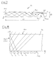
- Figure 8 shows a view of the reflection channel 14 in a height direction z corresponding viewing direction, it can be seen how the light emitted from the light-emitting diodes at a substantially along the Longitudinal x extending inner surface 14c of a side wall 14 d of the reflection channel 14 are reflected, so that even in the critical with respect to a uniform illumination edge regions of the detection area 12 and the reflection channel 14 results in a satisfactorily unified radiation intensity.
- the size ratio of a longitudinal extension 17 of the reflection channel 14 measured between a light inlet side 14a facing the light-emitting diodes 4 and a light exit side 14b facing the detection region 12 or the conveying element 3 is normal to the longitudinal extent 17 Height extension 23 of the reflection channel 14 (shown in Figure 5 and Figure 7 ) is in a range between 5: 1 to 10: 1, preferably in a range between 6.5: 1 to 8.5: 1.
- the size of the light-emitting angle ie that conical region within which 4 light beams are emitted by the light-emitting diodes in the direction of the light entrance side 14a of the reflection channel 14, is selected so that in the above-mentioned size ratios of the reflection channel optimal scattering the light beams emitted by the light emitting diodes results.
- the light-emitting angle of the light-emitting diodes 4 is in a range between 90 ° and 150 °, preferably in a range between 110 ° and 130 °. According to the present embodiment, a light-emitting angle of the light-emitting diodes 4 of 120 ° has proven to be particularly advantageous.
- a longitudinal extent 17 of at least 60 [mm], preferably a longitudinal extent 17 between 80 [mm] and 100 [mm], and a vertical extent 23 between 5 [mm] and 20 that extends normal to the longitudinal extent 17 are used as concrete dimensions for dimensioning the reflection channel 14 [mm], preferably a height extension 23 between 9 [mm] and 15 [mm] proposed.
- a reflection channel 14 which has a longitudinal extension 17 of 90 [mm] and a height extension 23 of 12 [mm], ie a size ratio of the longitudinal extension 17 to the height extension 23 of 7.5: 1, has proved to be particularly ideal with regard to the optical criteria already described has (this at a light-emitting angle of the light-emitting diodes 4 of 120 °).
- a (in the transverse direction y extending) width extension 18 of the reflection channel 14 can be selected according to a respective existing width of the detection area 12.
- the reflection channel 14 in a first embodiment according to Figure 5 has a substantially rectangular opening cross-section or a cuboid shape
- the opening cross section of the reflection channel 14 in one of the detection area 12 and the conveying element 3 facing Direction which according to Figure 6 the longitudinal direction x corresponds, extended.
- the opening cross section of the reflection channel 14 on the side of the light exit side 14b is greater than on the light entry side 14a.
- the optical device 6 comprises at least one Fresnel lens 15.
- the step-shaped ring structure is already well known, a very good optical alignment of the light emitted from the light-emitting diodes 4 light beams and thus a homogenization of the present in the detection area 12 radiation intensity is achieved.
- the Fresnel lens 15 is arranged downstream of the reflection channel 14 in the longitudinal direction x, that is to say positioned between the detection region 12 or the delivery element 3 and the light exit side 14b of the reflection channel 14.
- a plurality of Fresnel lenses 15 may be arranged one behind the other in order to achieve an ideal light characteristic in the detection region 12 or on the conveying element 3.
- a plurality of Fresnel lenses 15 may be juxtaposed (in the transverse direction y or in the height direction z), e.g. overlapping each other, be arranged.
- At least one further diffuser 16 is arranged between the Fresnel lens 15 and the conveying element 3, which serves for even better diffusion of the light beams emitted by the light-emitting diodes 4 or optimal equalization of the radiation intensity present in the detection area 12.
- the diffuser 16 may be a diffuser of conventional design, e.g. around a lens or a scattering foil.
- the Fresnel lenses 15 are held as well as the reflection channel 14 and the optional provided diffuser 16 with holding devices, not shown.
Abstract
Description
Vorrichtung zum Erfassen und Erkennen von Objekten eines Materialstromes, umfassend mindestens eine Kamera, welche Bilddaten der Objekte an eine Auswerteeinrichtung zwecks Ermittlung von Eigenschaften der Objekte des Materialstromes wie Materialzusammensetzung, Farbe, Größe oder dergleichen übermittelt, sowie eine beliebige Anzahl vorzugsweise reihenförmig angeordneter Leucht-Dioden, welche einer Beleuchtung des Materialstromes dienen, wobei der Materialstrom mittels eines Förderelementes transportiert und an einem Erfassungsbereich der Kamera(s) vorbeigeführt wird und wobei zwischen den Leucht-Dioden und dem vorzugsweise am Förderelement lokalisierten Erfassungsbereich eine optische Einrichtung angeordnet ist, welche eine Diffusion des von den Leucht-Dioden emittierten Lichtes bewirkt, gemäß dem Oberbegriff des Anspruchs 1.Device for detecting and detecting objects of a material flow, comprising at least one camera, which transmits image data of the objects to an evaluation device for the purpose of determining properties of the objects of the material flow such as material composition, color, size or the like, as well as any number preferably light-emitting diodes arranged in rows which serve to illuminate the material flow, wherein the material flow is transported by means of a conveying element and past a detection range of the camera (s) and wherein between the light-emitting diodes and the preferably located on the conveyor element detection area, an optical device is arranged, which is a diffusion of caused by the light-emitting diodes light, according to the preamble of claim 1.
Bei derartigen Vorrichtungen zum Erfassen und Erkennen von Objekten, z.B. in Sortieranlagen, werden Kameras, meistens Zeilenkameras, eingesetzt, an denen Objekte eines Materialstromes vorbeigeführt und von den Kameras bzw. von einer mit den Kameras assoziierten Auswerteeinrichtung entsprechend erkannt und zugeordnet werden. Diese Erkennung und Zuordnung kann sich auf verschiedene Eigenschaften der Objekte beziehen wie etwa Materialzusammensetzung, Farbe, Größe oder dergleichen. Die so gewonnenen Informationen dienen in weiterer Folge einer Steuerung nachfolgender Prozessabläufe, insbesondere der Steuerung einer Sortiereinrichtung, die die Objekte in unterschiedliche Fraktionen sortiert.In such devices for detecting and recognizing objects, e.g. In sorting systems, cameras, usually line scan cameras, are used, on which objects of a material stream are guided past and correspondingly recognized and assigned by the cameras or by an evaluation device associated with the cameras. This recognition and association may relate to various properties of the objects, such as material composition, color, size, or the like. The information thus obtained subsequently serves to control subsequent process sequences, in particular the control of a sorting device which sorts the objects into different fractions.
Durchsichtige oder durchscheinende Güter werden hierbei im Durchlicht- bzw. Transmissionsverfahren analysiert. Die Lichtquellen durchleuchten dabei den zu analysierenden Materialstrom, wobei den Lichtquellen gegenüberliegende Kameras das den Materialstrom durchscheinende Licht der Lichtquellen empfangen, was eine zuverlässigere Erkennung, etwa der einzelnen Fraktionen eines Sortiergutes, ermöglicht. Als Lichtquellen für das Durchleuchten können Leuchtstoffröhren verwendet werden.Transparent or translucent goods are analyzed by transmitted light or transmission. The light sources illuminate the analyzer Material flow, the light sources opposite cameras receive the material flow translucent light of the light sources, which allows a more reliable detection, such as the individual fractions of a sorted material. Fluorescent tubes can be used as light sources for transillumination.
Bei Sortiereinrichtungen neuerer Bauart werden jedoch bevorzugt Leucht-Dioden (LEDs) als Lichtquellen verwendet, da sich diese aufgrund ihrer Energieeffizienz und aufgrund einer selektiven Ansteuerbarkeit hinsichtlich Helligkeit und/oder Frequenz als vorteilhaft erweisen. Eine derartige Sortiereinrichtung ist beispielsweise aus der
Die Leucht-Dioden werden üblicherweise reihen- bzw. matrixförmig angeordnet und erstrecken sich zur Gänze oder teilweise über die Breite eines jeweiligen Förderelementes, auf welchem der Materialstrom transportiert wird. Beim Förderelement handelt es sich etwa um eine transparente Rutsche einer Sortieranlage oder um ein transparentes Förderband.The light-emitting diodes are usually arranged in rows or in a matrix and extend in whole or in part over the width of a respective conveying element on which the material flow is transported. The conveying element is, for example, a transparent chute of a sorting system or a transparent conveyor belt.
Um Objekte des Materialstroms zuverlässig analysieren und erkennen zu können, ist es von Bedeutung, dass ein jeweils vorgesehener Erfassungsbereich der Kamera, also ein definierter Abschnitt des Förderelementes, möglichst gleichmäßig, d.h. mit gleichmäßiger Strahlungsintensität ausgeleuchtet wird.In order to be able to reliably analyze and recognize objects of the material flow, it is important that a respectively provided detection range of the camera, that is to say a defined section of the conveying element, be as uniform as possible. is illuminated with uniform radiation intensity.
Die vorliegende Erfindung betrifft somit die Erzeugung bzw. Aufbereitung jenes Lichtes, welches auf den Objekten des Materialstromes auftrifft bzw. durch die Materialstrom-Objekte hindurchscheint oder von diesen reflektiert wird, um anschließend von einer oder mehreren Kameras erfasst und ausgewertet zu werden. Insofern könnte beim von den Leucht-Dioden abgestrahlten Licht auch von "Informationslicht" die Rede sein, also von Licht, welches (im Unterschied zu diversen Hintergrundbeleuchtungen) zu jenem Zweck mit den Objekten des Materialstromes in Kontakt gebracht wird, um Aufschluss über deren Eigenschaften zu geben.The present invention thus relates to the generation or processing of that light which impinges on the objects of the flow of material or through which material stream objects shine through or reflected by them, to subsequently detected by one or more cameras and to be evaluated. In this respect, the light emitted by the light-emitting diodes could also be referred to as "information light", ie light which (in contrast to various backlights) is brought into contact with the objects of the material flow for that purpose in order to gain information about their properties give.
Da die Leucht-Dioden annähernd punktförmige Lichtquellen darstellen, bedarf es zur Erzielung einer gleichmäßigen Beleuchtung des Materialstroms bzw. des Förderelementes weiterer Maßnahmen. In der
Die als Streufolien ausgeführten Diffusoren wandeln hierbei das von den annähernd punktförmigen Leucht-Dioden emittierte Licht in diffuses Licht um, wobei die Linse dazu dient, das vom diodenseitigen Diffusor abgestrahlte Licht in seiner Lichtstärke zu steuern und zu vergleichmäßigen.The diffusers designed as scattering foils convert the light emitted by the approximately point-shaped light-emitting diodes into diffuse light, the lens serving to control and equalize the light emitted by the diode-side diffuser in its light intensity.
Obwohl also durch eine derartige optische Einrichtung bereits eine wesentliche Verbesserung der Beleuchtung des Materialstroms bzw. des Kamera-Erfassungsbereichs erzielt wurde, besteht weiterer Entwicklungsbedarf.Although a substantial improvement in the illumination of the material flow or the camera detection range has already been achieved by such an optical device, there is a further need for development.
Die beschriebene optische Einrichtung bedingt nämlich eine relativ aufwändige und kostenintensive Fertigung.Namely, the described optical device requires a relatively complex and expensive production.
Als Leucht-Dioden dürfen nur LEDs mit im Wesentlichen einheitlicher Lichtstärke eingesetzt werden. Ist die Lichtstärketoleranz der Leucht-Dioden zu groß, so würden die mittels der Kamera detektierten, unterschiedlichen Strahlungsintensitäten einzelner Leucht-Dioden zu einer schlechteren Erkennung von zu sortierenden Objekten bzw. zu einer verminderten Klassifizierungsgüte einzelner Sortierfraktionen führen.As light-emitting diodes only LEDs with substantially uniform light intensity may be used. If the light intensity tolerance of the light-emitting diodes is too large, the By means of the camera detected, different radiation intensities of individual light-emitting diodes lead to a poorer detection of objects to be sorted or to a reduced Klassifizierungsgüte individual sorting fractions.
Um eine zufrieden stellende Erkennung unterschiedlicher Objekte des Materialstroms zu gewährleisten, muss als Linse ein poliertes Plexiglaselement höchster Qualität eingesetzt werden, welche entsprechend kostenintensiv in der Fertigung ist.In order to ensure a satisfactory detection of different objects of the material flow, the lens used must be a polished plexiglass element of the highest quality, which is correspondingly expensive in terms of production.
Aus Gründen einer Anpassung an die Linsengeometrie bzw. einer gewünschten Strahlungsintensitätsverteilung muss bei Mehrkamerasystemen eine überlappende Anordnung der Linsen vorgenommen werden, was eine komplizierte Halterung der Linsen und der Diffusoren und somit ebenfalls einen hohen Fertigungsaufwand erforderlich macht.For reasons of adaptation to the lens geometry or a desired radiation intensity distribution, an overlapping arrangement of the lenses must be made in multi-camera systems, which requires a complicated mounting of the lenses and the diffusers and thus also a high production cost.
Des weiteren reduzieren die bisher als Diffusoren eingesetzten Streufolien die Strahlungsintensität der Leucht-Dioden um bis zu 30%, was einen erhöhten Energiebedarf nach sich zieht.Furthermore, the scattering films used so far as diffusers reduce the radiation intensity of the light-emitting diodes by up to 30%, which entails an increased energy requirement.
In der Praxis ergeben sich bei gattungsgemäßen Systemen überdies - über die Breite des Erfassungsbereichs bzw. des Förderelementes betrachtet - immer noch beträchtliche Unterschiede der Strahlungsintensität. Da nämlich die Ausrichtung der von den Leucht-Dioden emittierten Lichtstrahlen im Wesentlichen zentrisch auf die Kamera bzw. ein Kameraobjektiv erfolgt, ergeben sich je nach Position der Leucht-Dioden relativ zur Kamera bzw. zum Kameraobjektiv örtlich unterschiedliche Strahlungswinkel der Lichtstrahlen. Bei Messungen im Transmissionsverfahren wird eine detektierte Strahlungsintensität jedoch wesentlich vom jeweils vorhandenen Strahlungswinkel beeinflusst, was dazu führt, dass im Erfassungsbereich lokal unterschiedliche Verhältnisse von gerichteten und ungerichteten Lichtstrahlungs-Anteilen vorgefunden werden.In practice, in generic systems moreover, viewed over the width of the detection area or of the conveying element, there are still considerable differences in the radiation intensity. Since the orientation of the light beams emitted by the light-emitting diodes is essentially centered on the camera or a camera lens, depending on the position of the light emitting diodes relative to the camera or the camera lens, spatially different radiation angles of the light beams result. For measurements in the transmission method, however, a detected radiation intensity is significantly influenced by the respective existing radiation angle, which leads to the fact that in the Detection area locally different ratios of directional and non-directional light radiation components can be found.
Insbesondere in den Randbereichen des Erfassungsbereichs bzw. des Förderelementes kann es deshalb zu Fehldetektionen kommen. So werden etwa dunkelgrüne oder dunkelbraune Glasscherben im Materialstrom oft fälschlicherweise als (auszusortierende) Störstoffe klassifiziert, obwohl lediglich Objekte aus Keramik, Stein oder Porzellan ("KSP"-Objekte) aus dem Materialstrom auszusortieren wären.Therefore, in particular in the edge regions of the detection area or of the conveying element, misdetections may occur. For example, dark green or dark brown glass shards in the material stream are often erroneously classified as contaminants to be sorted out, although only objects made of ceramic, stone or porcelain ("CSF" objects) would have to be sorted out of the material flow.
Es ist daher das Ziel der vorliegenden Erfindung, die genannten Nachteile zu beseitigen und eine verbesserte Vorrichtung zum Erfassen und Erkennen von Objekten eines Materialstromes bereitstellen, die eine möglichst gleichmäßige Beleuchtung des Materialstroms bzw. eines am Förderelement vorgesehenen Erfassungsbereichs der Kamera(s) ermöglichen.It is therefore the object of the present invention to eliminate the disadvantages mentioned and to provide an improved device for detecting and detecting objects of a material flow, which allow the most uniform possible illumination of the material flow or a detection range of the camera (s) provided on the conveying element.
Entlang der gesamten Breite bzw. auf dem gesamten Areal des am Förderelement vorgesehenen Erfassungsbereichs soll eine im Wesentlichen gleich große Strahlungsintensität der von den Leucht-Dioden emittierten Lichtstrahlen gewährleistet sein, sodass eine höhere Erkennungsrate der im Materialstrom erfassten Objekte ermöglicht und Fehldetektionen vermieden werden.Along the entire width or over the entire area of the detection area provided on the conveying element, a substantially equal radiation intensity of the light beams emitted by the light-emitting diodes should be ensured, so that a higher detection rate of the objects detected in the material flow is possible and incorrect detections are avoided.
Erfindungsgemäß wird dieses Ziel durch eine Vorrichtung mit den kennzeichnenden Merkmalen des Anspruchs 1 gelöst.This object is achieved by a device having the characterizing features of claim 1.
Eine gattungsgemäße Vorrichtung zum Erfassen und Erkennen von Objekten eines Materialstromes umfassend mindestens eine Kamera, welche Bilddaten der Objekte an eine Auswerteeinrichtung zwecks Ermittlung von Eigenschaften der Objekte des Materialstromes wie Materialzusammensetzung, Farbe, Größe oder dergleichen übermittelt, sowie eine beliebige Anzahl an vorzugsweise reihenförmig angeordneten Leucht-Dioden, welche einer Beleuchtung des Materialstromes dienen, wobei der Materialstrom mittels eines Förderelementes transportiert und an einem Erfassungsbereich der Kamera(s) vorbeigeführt wird.A generic device for detecting and recognizing objects of a material flow comprising at least one camera, which image data of the objects to an evaluation device for the purpose of determining properties of the objects of the material flow such as material composition, Color, size or the like transmitted, as well as any number of preferably arranged in rows light-emitting diodes, which serve to illuminate the material flow, wherein the material flow is transported by a conveyor element and past a detection range of the camera (s).
In einer bevorzugten Ausgestaltung der erfindungsgemäßen Vorrichtung passiert das Förderelement hierbei den Kamera-Erfassungsbereich, sodass der Kamera-Erfassungsbereich also direkt am Förderelement lokalisiert ist. Ebenso wäre es jedoch möglich, dass das Förderelement die auf diesem transportierten Materialstrom-Objekte abwirft und der Kamera-Erfassungsbereich diesfalls auf den Fallweg bzw. auf eine Wurfparabel der frei fallenden Materialstrom-Objekte gerichtet ist, ohne dass sich das Förderelement im Hintergrund der Materialstrom-Objekte befinden würde.In a preferred embodiment of the device according to the invention, the conveying element in this case passes through the camera detection area, so that the camera detection area is thus located directly on the conveying element. Likewise, however, it would be possible that the conveyor element throws off the material flow objects transported on the latter and the camera detection area is in this case directed onto the fall path or onto a parabola of the freely falling material flow objects without the conveyor element projecting in the background of the material flow. Objects would be located.
Zwischen den Leucht-Dioden und dem (auf dem Förderelement transportierten oder im freien Fall befindlichen) Materialstrom ist eine optische Einrichtung angeordnet, welche eine Diffusion des von den Leucht-Dioden emittierten Lichtes bewirkt. Erfindungsgemäß ist es vorgesehen, dass die optische Einrichtung mindestens einen auf seinen Innenseiten verspiegelten Reflexionskanal umfasst.Between the light-emitting diodes and the (transported on the conveying element or in free fall) material flow, an optical device is arranged, which causes a diffusion of light emitted by the light-emitting diodes. According to the invention, it is provided that the optical device comprises at least one reflection channel mirrored on its insides.
Indem die von den Leucht-Dioden emittierten Lichtstrahlen im innenseitig verspiegelten Reflexionskanal mehrfach reflektiert werden, kann eine deutlich bessere Diffusion der Lichtstrahlen erzielt werden als bei Vorrichtungen gemäß dem Stand der Technik.By multiply reflecting the light beams emitted by the light-emitting diodes in the inside mirrored reflection channel, a significantly better diffusion of the light beams can be achieved than with devices according to the prior art.
Die von mehreren Leucht-Dioden emittierten und in eine Licht-Eintrittsseite des Reflexionskanals eintretenden Lichtstrahlen können bei deren Austritt auf einer dem Kamera-Erfassungsbereich bzw. dem Materialstrom zugewandten Licht-Austrittsseite des Reflexionskanals hinsichtlich ihres Ursprungs nicht mehr einzelnen Leucht-Dioden zugeordnet werden. Hingegen ergibt sich entlang der gesamten Breite bzw. auf der gesamten Fläche der Licht-Austrittsseite des Reflexionskanals eine nahezu konstante Strahlungsintensität.The light rays emitted by a plurality of light-emitting diodes and entering a light entrance side of the reflection channel may exit at a camera detection area or the material flow facing light exit side of the reflection channel are no longer assigned to individual light-emitting diodes with respect to their origin. By contrast, an almost constant radiation intensity results along the entire width or over the entire surface of the light exit side of the reflection channel.
Das auf den Objekten des Materialstromes auftreffende und diese durchscheinende oder von diesen reflektierte Licht bietet aufgrund seiner gleichmäßigen Strahlungsintensität ideale Vorraussetzungen für ein nachfolgendes Erfassen und Auswerten der von den Materialstrom-Objekten auf die Kamera(s) gelangenden Lichtstrahlen.The incident on the objects of the material flow and these translucent or reflected by these light provides ideal conditions for a subsequent detection and evaluation of the material stream objects on the camera (s) reaching light rays due to its uniform radiation intensity.
Indem die verspiegelten Innenseiten des Reflexionskanals aufgrund ihrer Reflexionseigenschaften quasi das Vorhandensein zusätzlicher Lichtquellen bzw. Leucht-Dioden simulieren, ist der Abfall der Strahlungsintensität auch in den bisher hinsichtlich einer zufriedenstellenden Ausleuchtung kritischen Randbereichen Erfassungsbereichs bzw. des Förderelementes vernachlässigbar gering.Since the mirrored inner sides of the reflection channel virtually simulate the presence of additional light sources or light-emitting diodes due to their reflection properties, the decrease in the radiation intensity is negligibly small even in the marginal detection area or conveying element that has hitherto been critical for satisfactory illumination.
Durch die Gewährleistung einer gleichmäßigen Beleuchtung des Materialstroms bzw. des Kamera-Erfassungsbereichs wird eine sichere Erkennung von Objekten des Materialstroms ermöglicht und die Anzahl von Fehlerkennungen kann deutlich gesenkt werden.Ensuring a uniform illumination of the material flow or the camera detection area enables reliable detection of objects of the material flow and the number of fault detections can be significantly reduced.
Aufgrund der idealen Vergleichmäßigung der Strahlungsintensität durch den erfindungsgemäßen Reflexionskanal können fortan auch Leucht-Dioden mit größerer Lichtstärketoleranz eingesetzt werden, was die Herstellungskosten gattungsgemäßer Beleuchtungseinrichtungen verringert.Due to the ideal equalization of the radiation intensity through the reflection channel according to the invention, light-emitting diodes with greater light intensity tolerance can henceforth be used, which reduces the production costs of generic lighting devices.
Als weiterer Vorteil der Erfindung ist anzuführen, dass bei Vorsehung eines erfindungsgemäßen Reflexionskanals anstelle konventioneller Streudiffusoren, welche viele Streupunkte in einer Ebene aufweisen, ein deutlich geringerer Verlust an Strahlungsintensität der von den Leucht-Dioden emittierten Lichtstrahlen stattfindet. Dies macht es wiederum möglich, Leucht-Dioden mit geringerer Leistungsaufnahme zu betreiben.A further advantage of the invention is that, when a reflection channel according to the invention is provided instead of conventional scattering diffusers, which have many scattering points in one plane, a significantly lower loss of radiation intensity of the light beams emitted by the light-emitting diodes takes place. This in turn makes it possible to operate light-emitting diodes with lower power consumption.
Im Gegensatz zu einem bereits bekannten Objekterkennungs-System, welches zufolge des Strahlungsintensitätsabfalls in den Randbereichen des Erfassungsbereichs eine im Verhältnis zur jeweiligen Erfassungsbereichs-Breite größere Baubreite der optischen Einrichtung (insbesondere der Linsen und Leucht-Dioden-Anordnung) - was im Falle Mehrfach-Kamerasystemen wiederum eine versetzte Anordnung der einzelnen Kameras erforderlich machte, um den Materialstrom lückenlos erfassen zu können - ist es nunmehr möglich, die einzelnen Kameras in einer Ebene anzuordnen. Im Falle einer Vorsehung mehrerer Kameras wird also eine vereinfachte Montage ermöglicht.In contrast to a previously known object recognition system, which according to the radiation intensity decrease in the edge regions of the detection area has a greater width in relation to the respective detection area width of the optical device (in particular the lenses and light-emitting diode array) - which in the case of multiple camera systems In turn, a staggered arrangement of the individual cameras required in order to be able to detect the material flow without gaps - it is now possible to arrange the individual cameras in a plane. In the case of a provision of multiple cameras so a simplified installation is possible.
In einer bevorzugten Ausführungsvariante der vorliegenden Erfindung weist der Reflexionskanal einen im Wesentlichen rechteckigen Öffnungsquerschnitt auf, sodass sich also ein im Wesentlichen quaderförmiger Reflexionskanal ergibt. Indem die Innenseiten des Reflexionskanal jeweils unter einem Winkel von 90° zueinander angeordnet sind, wird eine vielfache Ablenkung und somit Streuung der in den Reflexionskanal eintretenden, von den Leucht-Dioden emittierten Lichtstrahlen erzielt. Darüber hinaus ist ein rechteckiger bzw. quaderförmiger Reflexionskanal einfach zu fertigen.In a preferred embodiment of the present invention, the reflection channel has a substantially rectangular opening cross-section, so that thus results in a substantially cuboid reflection channel. By the inner sides of the reflection channel are each arranged at an angle of 90 ° to each other, a multiple deflection and thus scattering of entering the reflection channel, emitted by the light-emitting diodes light beams is achieved. In addition, a rectangular or cuboid reflection channel is easy to manufacture.
In einer Fortbildung der vorliegenden Erfindung ist es vorgesehen, dass sich der Öffnungsquerschnitt des Reflexionskanals in einer dem Erfassungsbereich zuweisenden Richtung, also in Lichtstrahlen-Emissionsrichtung erweitert.In a further development of the present invention, it is provided that the opening cross-section of the reflection channel widens in a direction assigning the detection area, ie in the light beam emission direction.
Auf diese Weise wird eine günstigere Ausbreitungscharakteristik der von den Leucht-Dioden emittierten Lichtstrahlen erzielt und es kann ein größerer Erfassungsbereich ausgeleuchtet werden.In this way, a more favorable propagation characteristic of the light beams emitted from the light-emitting diodes is achieved, and a larger detection range can be illuminated.
In praktischen Versuchen hat es sich erwiesen, dass eine besonders effiziente Streuung bzw. Vergleichmäßigung der von den Leucht-Dioden emittierten Lichtstrahlen eintritt, wenn das Größenverhältnis einer zwischen einer den Leucht-Dioden zugewandten Licht-Eintrittsseite und einer dem Erfassungsbereich zugewandten Licht-Austrittsseite gemessenen Längserstreckung des Reflexionskanals zu einer zur Längserstreckung normal verlaufenden Höhenerstreckung des Reflexionskanals in einem Bereich zwischen 5:1 bis 10:1, vorzugsweise in einem Bereich zwischen 6,5:1 bis 8,5:1 liegt.In practical experiments, it has been found that particularly efficient scattering or equalization of the light beams emitted by the light-emitting diodes occurs when the size ratio of a longitudinal extension measured between a light entry side facing the light-emitting diodes and a light exit side facing the detection area of the reflection channel to a longitudinal extent of the normal extending height of the reflection channel in a range between 5: 1 to 10: 1, preferably in a range between 6.5: 1 to 8.5: 1.
Im Zusammenhang mit den gewählten Größenverhältnissen des Reflexionskanals ist es des weiteren von Bedeutung, wie groß ein auf den Reflexionskanal gerichteter Licht-Abstrahlwinkel der Leucht-Dioden ist. Die Größe des Licht-Abstrahlwinkels, also jenes kegelförmigen Bereichs, innerhalb welchem von den Leucht-Dioden Lichtstrahlen abgestrahlt werden, ist so gewählt, dass sich bei den vorangehend genannten Größenverhältnissen des Reflexionskanals eine optimale Streuung der von den Leucht-Dioden abgestrahlten Lichtstrahlen ergibt. In einer bevorzugten Ausführungsvariante der Erfindung ist es daher vorgesehen, dass Licht-Abstrahlwinkel der Leucht-Dioden in einem Bereich zwischen 90° und 150°, vorzugsweise in einem Bereich zwischen 110° und 130° liegt.In connection with the selected size ratios of the reflection channel, it is also of importance how large a directed on the reflection channel light-emitting angle of the light-emitting diodes. The size of the light emission angle, ie the conical region within which light rays are emitted by the light-emitting diodes, is chosen such that, given the above-mentioned size ratios of the reflection channel, optimum scattering of the light rays emitted by the light-emitting diodes results. In a preferred embodiment of the invention, it is therefore provided that the light-emitting angle of the light-emitting diodes is in a range between 90 ° and 150 °, preferably in a range between 110 ° and 130 °.
Bei einer zu kurz gewählten Längserstreckung des erfindungsgemäßen Reflexionskanals ergäbe sich eine zu geringe Streuung bzw. Vergleichmäßigung der von den Leucht-Dioden emittierten Lichtstrahlen, während bei einer zu groß gewählten Längserstreckung des Reflexionskanals mit einem Intensitätsverlust der Lichtstrahlen zu rechnen wäre, ohne dass jedoch eine relevante Verbesserung hinsichtlich der Lichtstrahlen-Streuung erzielt würde.If the longitudinal extension of the reflection channel according to the invention is selected too short, the light rays emitted by the light-emitting diodes would be too small or uniform, while if the longitudinal extension of the reflection channel would be too large, the reflection channel would be too large Intensity loss of the light rays would be expected, but without a relevant improvement in the light beam scattering would be achieved.
Beruhend auf experimenteller Forschungsarbeit zur optimalen Dimensionierung des erfindungsgemäßen Reflexionskanals ist es daher in einer bevorzugten Ausführungsvariante vorgesehen, dass der Reflexionskanal eine Längserstreckung von mindestens 60 [mm], vorzugsweise eine Längserstreckung zwischen 80 [mm] und 100 [mm] aufweist.Based on experimental research for optimum dimensioning of the reflection channel according to the invention, it is therefore provided in a preferred embodiment that the reflection channel has a longitudinal extent of at least 60 [mm], preferably a longitudinal extent of between 80 [mm] and 100 [mm].
Hierbei weist der Reflexionskanal eine normal zur Längserstreckung verlaufende Höhenerstreckung zwischen 5 [mm] und 20 [mm], vorzugsweise eine Höhenerstreckung zwischen 9 [mm] und 15 [mm] auf.In this case, the reflection channel has a vertical extent extending between 5 [mm] and 20 [mm], preferably a height extent between 9 [mm] and 15 [mm], extending normal to the longitudinal extent.
Durch derartige Größendimensionierungen des Reflexionskanals ist eine höchst effiziente Streuung bzw. Vergleichmäßigung der von den Leucht-Dioden emittierten Lichtstrahlen sowie eine optimale Energieeffizienz der Leucht-Dioden gewährleistet.By such size dimensions of the reflection channel highly efficient scattering or equalization of the light emitted from the light-emitting diodes light beams and optimum energy efficiency of the light-emitting diodes is ensured.
In einer bevorzugten Ausführungsvariante der vorliegenden Erfindung ist der Reflexionskanal in kostengünstiger Weise aus Blech gefertigt.In a preferred embodiment of the present invention, the reflection channel is inexpensively made of sheet metal.
In einer Fortbildung der vorliegenden Erfindung ist es vorgesehen, dass die optische Einrichtung mindestens eine Fresnel-Linse umfasst. Durch Vorsehung einer (stufenförmigen) Fresnel-Linse kann eine noch bessere Diffusion und optische Ausrichtung der von den Leucht-Dioden emittierten Lichtstrahlen erzielt und somit die Detektionsgüte der erfindungsgemäßen Vorrichtung erhöht werden.In a further development of the present invention, it is provided that the optical device comprises at least one Fresnel lens. By providing a (stepped) Fresnel lens, an even better diffusion and optical alignment of the light beams emitted by the light-emitting diodes can be achieved and thus the detection quality of the device according to the invention can be increased.
In einer bevorzugten Ausführungsvariante ist es weiters vorgesehen, mehrere Fresnel-Linsen hintereinander anzuordnen, um im Erfassungsbereich eine ideal vergleichmäßigte Strahlungsintensität der von den Leucht-Dioden emittierten Lichtstrahlen zu erzielen.In a preferred embodiment, it is further provided to arrange several Fresnel lenses in a row, in order to achieve an ideally uniform radiation intensity of the light beams emitted by the light-emitting diodes in the detection area.
In einer bevorzugten Anordnungsvariante ist es vorgesehen, dass die mindestens eine Fresnel-Linse zwischen dem Reflexionskanal und dem (vorzugsweise am Förderelement lokalisierten) Erfassungsbereich angeordnet ist. Auf diese Weise können allfällige auf der Licht-Austrittsseite des Reflexionskanals vorhanden Unregelmäßigkeiten der Strahlungsintensität egalisiert werden.In a preferred arrangement variant, it is provided that the at least one Fresnel lens is arranged between the reflection channel and the (preferably located on the conveyor element) detection area. In this way, any irregularities of the radiation intensity present on the light exit side of the reflection channel can be equalized.
In einer weiteren bevorzugten Anordnungsvariante der Erfindung ist es vorgesehen, dass es sich bei den Leucht-Dioden um gepulst betreibbare Leucht-Dioden, vorzugsweise um gepulst betreibbare RGB- sowie UV-Leucht-Dioden handelt. Auf diese Weise kann die von den Kameras gemessene Strahlungsintensität maximiert bzw. die Kamerazeilen-Erkennungsrate erhöht werden. Der Einsatz von gepulsten RGB- und UV-Leucht-Dioden erweist sich insbesondere zur Sonderglaserkennung als besonders vorteilhaft.In a further preferred arrangement variant of the invention, it is provided that the light emitting diodes are pulsed light emitting diodes, preferably pulsed RGB and UV light emitting diodes. In this way, the radiation intensity measured by the cameras can be maximized or the camera line recognition rate can be increased. The use of pulsed RGB and UV light-emitting diodes proves to be particularly advantageous for special glass detection.
Die Erfindung wird nun anhand eines Ausführungsbeispiels näher erläutert. Dabei zeigt:
- Fig.1
- eine schematische Darstellung einer Sortiereinrichtung gemäß dem Stand der Technik
- Fig.2
- eine schematische Darstellung einer optischen Einrichtung zur Vergleichmäßigung der Strahlungsintensität gemäß dem Stand der Technik
- Fig.3
- eine schematische Darstellung eines Strahlungsintensitäts-Verlaufs entlang der Breite eines auf einem Förderelement lokalisierten Kamera-Erfassungsbereichs (bei eine Beleuchtungseinrichtung gemäß dem Stand der Technik)
- Fig.4
- eine erste Ausführungsvariante einer erfindungsgemäßen Objekterkennungs-Vorrichtung in Seitenansicht
- Fig.5
- eine erste Ausführungsvariante einer erfindungsgemäßen Objekterkennungs-Vorrichtung in isometrischer Explosions-Darstellung
- Fig.6
- eine zweite Ausführungsvariante einer erfindungsgemäßen Objekterkennungs-Vorrichtung in isometrischer Explosions-Darstellung
- Fig.7
- eine schematische Darstellung des Reflexionsverhaltens von Lichtstrahlen innerhalb eines erfindungsgemäßen Reflexionskanals
- Fig.8
- eine schematische Darstellung des Reflexionsverhaltens von Lichtstrahlen innerhalb eines erfindungsgemäßen Reflexionskanals
- Fig.1
- a schematic representation of a sorting device according to the prior art
- Fig.2
- a schematic representation of an optical device for equalizing the radiation intensity according to the prior art
- Figure 3
- a schematic representation of a radiation intensity profile along the width of a camera detection area located on a conveyor element (in a lighting device according to the prior art)
- Figure 4
- a first embodiment of an object detection device according to the invention in side view
- Figure 5
- a first embodiment of an object detection device according to the invention in an isometric exploded view
- Figure 6
- a second embodiment of an object detection device according to the invention in an isometric exploded view
- Figure 7
- a schematic representation of the reflection behavior of light rays within a reflection channel according to the invention
- Figure 8
- a schematic representation of the reflection behavior of light rays within a reflection channel according to the invention
Ersichtlich ist eine Förderanlage 19, bei welcher mittels eines Rollenförderers 20 Objekte 5 eines zu selektierenden Materialstroms zu einem als Rutsche ausgeführten Förderelement 3 befördert werden.A conveying
Die auf dem Förderelement 3 geführten Objekte 5 des Materialstroms, bewegen sich, der Schwerkraft folgend, an einem Erfassungsbereich 12 von nebeneinander angeordneten Kameras 1 vorbei. Die Kameras 1 sind in einer Weise nebeneinander positioniert, dass sich die Einzel-Erfassungsbereiche benachbarter Kameras 1 in der Ebene des Förderelementes 3 überlappen und gemeinsam den zu überwachenden Erfassungsbereich 12 ergeben. Als Erfassungsbereich 12 kann ein zeilenförmiger oder auch ein flächenförmiger Bereich des Förderelementes 3 definiert sein.The
Es sei angemerkt, dass die Objekte 5 des Materialstroms auch in einer Position von den Kameras 1 detektiert werden können, in welchen sich die Objekte 5 nicht mehr auf dem Förderelementes 3 befinden, sondern von diesem abgeworfen wurden und sich im freien Fall befinden. In solchem Falle wäre der Kamera-Erfassungsbereich 12 nicht am Förderelement 3 lokalisiert, sondern in einem nicht substanziell lokalisierbaren Freifall-Bereich. Unabhängig von der konkreten Ausführungsvariante der Erkennungsvorrichtung liegt der Erfassungsbereich 12 jedenfalls stets im Bereich Förderwegs des Materialstroms.It should be noted that the
Bei den Kameras 1 kann es sich um beliebige Sensorelemente handeln, welche zu einem Empfang optischer Informationen geeignet sind, z.B. für farb- oder monochromen Empfang geeignete CMOS-Flächenkameras.The cameras 1 may be any sensor elements suitable for receiving optical information, e.g. CMOS area cameras suitable for color or monochrome reception.
Während auf der einen Seite des Förderelementes 3 bzw. des Erfassungsbereichs 12 die z.B. als Zeilenkameras ausgeführten und mit einer nicht dargestellten Auswerteeinrichtung sowie in weiterer Folge mit einer Sortiereinrichtung 10 verbundenen Kameras 1 angeordnet sind, so ist auf der anderen Seite des Erfassungsbereichs 12 bzw. des Förderelementes 3 eine Beleuchtungsvorrichtung 22 angeordnet.While on one side of the
Die Beleuchtungsvorrichtung 22 umfasst eine Vielzahl an Leucht-Dioden 4, welche über eine Steuerungsvorrichtung 13 variabel ansteuerbar sind und welche mittels von ihnen emittierter Lichtstrahlen das transparent ausgeführte Förderelement 3 sowie die Objekte 5 des Materialstroms (sofern diese ebenfalls transparent sind) durchleuchten. Als Leucht-Dioden 4 können z.B. Weißlicht- oder Infrarot-Dioden Einsatz finden.The
In einer speziellen Ausführungsvariante der Erfindung handelt sich bei den Leucht-Dioden 4 um gepulst betreibbare LEDs, also um Leucht-Dioden mit gepulster Spannungs- bzw. Stromversorgung. Vorzugsweise werden hierbei gepulst betreibbare RGB-LEDs in Kombination mit gepulst betreibbaren UV-LEDs eingesetzt.In a special embodiment variant of the invention, the light-emitting
Besonders gute Bilddaten können durch einen Einsatz von gepulsten RGB- und UV-LEDs in Kombination mit einer monochromen CMOS-Flächenkamera erzielt werden.Particularly good image data can be achieved by using pulsed RGB and UV LEDs in combination with a monochrome CMOS area camera.
Eine Anordnung gemäß
Die durch das Vorbeigleiten der Objekte 5 bedingten Modifikationen der von den Leucht-Dioden 4 emittierten Lichtstrahlen werden von den Kameras 1 erfasst, womit Aufschluss über verschiedene Eigenschaften jeweiliger Objekte 5 des Materialstroms, wie etwa Materialzusammensetzung, Farbe, Größe oder dergleichen gewonnen werden kann.The modifications of the light beams emitted by the light-emitting
Die mittels der Kameras 5 generierten digitalen Bilder werden von der Auswerteeinrichtung nach vorgegebenen Kriterien analysiert, um die einzelnen Objekte 5 des Materialstroms hinsichtlich ihrer Beschaffenheit zu erkennen. Wird ein Objekt 5, z.B. aufgrund seiner hohen Lichtabsorption, als Störstoff qualifiziert, so kann es z.B. mittels Ausblasdüsen der Sortiereinrichtung 10 aus dem Materialstrom ausgeblasen bzw. in eine eigens dafür vorgesehenen Fraktion umgelenkt werden.The digital images generated by the
Im vorliegenden Ausführungsbeispiel interessiert insbesondere die Selektion eines Bruchglasmaterialstroms, wobei Störstoffe aus Keramik, Stein oder Porzellan (als "KSP"-Objekte bezeichnet) zu erkennen und in weiterer Folge aus dem Materialstrom auszuscheiden sind.In the present embodiment, in particular, the selection of a Bruchglasmaterialstroms interested, with impurities of ceramic, stone or porcelain (referred to as "KSP" objects) to recognize and are subsequently eliminated from the flow of material.
Da die Leucht-Dioden 4 annähernd punktförmige Lichtquellen darstellen, ist gemäß dem Stand der Technik eine in
Allerdings ergeben sich in der Praxis - über die Breite des Erfassungsbereichs 12 bzw. des Förderelementes 3 betrachtet - immer noch beträchtliche Unterschiede hinsichtlich der lokal vorhandenen Strahlungsintensität. Da nämlich die Ausrichtung der von den Leucht-Dioden 4 emittierten Lichtstrahlen im Wesentlichen zentrisch auf die Kamera 1 bzw. ein Kameraobjektiv 2 erfolgt, ergeben sich je nach Position der Leucht-Dioden 4 relativ zur Kamera 1 bzw. zum Kameraobjektiv 2 örtlich unterschiedliche Strahlungswinkel der Lichtstrahlen (siehe
Insbesondere in Randbereichen des Erfassungsbereichs 12 bzw. des Förderelementes 3 kann es deshalb zu Fehlerkennungen kommen bzw. ein Bruchglas-Objekt kann irrtümlicherweise als KSP-Objekt klassifiziert werden.In particular, in edge regions of the detection area 12 and the conveying
Ausschlaggebend für die Qualität der Objekt-Erkennungsfähigkeit der Sortiervorrichtung ist es aber, ob mittels der Leucht-Dioden 4 über die gesamte Breite des von den Kameras 1 überwachten Erfassungsbereichs 12 eine konstante Strahlungsintensität zum Beleuchten der Materialstrom-Objekte 5 realisiert werden kann. In
Die entlang der Erfassungsbereiche 12a, 12b zu verzeichnende Strahlungsintensität ist in der Praxis unstetig, sodass sich im Diagramm gemäß
Obwohl eine derartige, vollkommen gleichmäßig über den Erfassungsbereich 12 verteilte Strahlungsintensität eine idealisierte Annahme darstellt und in der Praxis nicht erreichbar ist, so kann diese mittels einer in den
Der Reflexionskanal 14 besitzt eine den Leucht-Dioden 4 zugewandte Licht-Eintrittsseite 14a und eine den Leucht-Dioden 4 abgewandte bzw. dem Förderelement 3 zugewandte Licht-Austrittsseite 14b. Wie in
Der Reflexionskanal 14 ist in einer bevorzugten Ausführungsvariante aus Blech gefertigt, kann jedoch auch anderen Werkstoffen, z.B. aus einem Kunststoff hergestellt sein.The
Die Spiegel- bzw. Reflexionseigenschaften der Innenseiten 14c des Reflexionskanals 14 können auf verschiedenste Weise hergestellt werden, so etwa durch eine entsprechende Oberflächenbehandlung wie z.B. Polieren oder durch Auftragen einer Oberflächenschicht mit hohen Reflexionseigenschaften oder durch Anbringen separater Spiegelelemente an den Reflexionskanal-Innenseiten 14c.The reflection properties of the insides 14c of the
Es sei angemerkt, dass die Innenseiten 14c des Reflexionskanals 14 vorzugsweise vollkommen verspiegelt sind, gegebenenfalls jedoch auch lediglich teilweise verspiegelt sein können.It should be noted that the
Der erfindungsgemäße Reflexionskanal 14 ist gemäß
Es sei angemerkt, dass der Reflexionskanal 14 in mehrere Module unterteilt sein kann bzw. dass eine beliebige Anzahl an separaten Reflexionskanälen 14 je nach Einsatzerfordernis nebeneinander bzw. zueinander beabstandet angeordnet sein kann. In Abhängigkeit einer gewünschten Geometrie des Erfassungsbereichs 12 können die Reflexionskanäle 14 hierbei, ebenso wie die Leucht-Dioden(-Reihen) 4, sowohl in einer normal zur Längsrichtung x verlaufenden Querrichtung y, als auch in einer Höhenrichtung z (welche einer Materialstrom-Transportrichtung entspricht) nebeneinander angeordnet sein.It should be noted that the
Um eine effiziente Streuung bzw. Vergleichmäßigung der von den Leucht-Dioden 4 emittierten Lichtstrahlen zu erzielen, wurden in experimenteller Forschungsarbeit geeignete Geometrien bzw. Größenverhältnisse des erfindungsgemäßen Reflexionskanals 14 ermittelt.In order to achieve an efficient scattering or equalization of the light beams emitted by the light-emitting
So ist es erfindungsgemäß vorgeschlagen, dass das Größenverhältnis einer zwischen einer den Leucht-Dioden 4 zugewandten Licht-Eintrittsseite 14a und einer dem Erfassungsbereich 12 bzw. dem Förderelement 3 zugewandten Licht-Austrittsseite 14b gemessenen Längserstreckung 17 des Reflexionskanals 14 zu einer zur Längserstreckung 17 normal verlaufenden Höhenerstreckung 23 des Reflexionskanals 14 (eingezeichnet in
Im Zusammenhang mit den gewählten Größenverhältnissen des Reflexionskanals ist es des weiteren von Bedeutung, wie groß ein auf den Reflexionskanal gerichteter Licht-Abstrahlwinkel der Leucht-Dioden 4 ist. Die Größe des Licht-Abstrahlwinkels, also jenes kegelförmigen Bereichs, innerhalb welchem von den Leucht-Dioden 4 Lichtstrahlen in Richtung der Licht-Eintrittsseite 14a des Reflexionskanals 14 abgestrahlt werden, ist so gewählt, dass sich bei den vorangehend genannten Größenverhältnissen des Reflexionskanals eine optimale Streuung der von den Leucht-Dioden abgestrahlten Lichtstrahlen ergibt. In einer bevorzugten Ausführungsvariante der Erfindung ist es daher vorgesehen, dass der Licht-Abstrahlwinkel der Leucht-Dioden 4 in einem Bereich zwischen 90° und 150°, vorzugsweise in einem Bereich zwischen 110° und 130° liegt. Gemäß vorliegendem Ausführungsbeispiel hat sich ein Licht-Abstrahlwinkel der Leucht-Dioden 4 von 120° als besonders vorteilhaft erwiesen.In connection with the selected size ratios of the reflection channel, it is also of importance how large a directed onto the reflection channel light-emitting angle of the light-emitting
Als konkrete Maße zur Dimensionierung des Reflexionskanals 14 sind erfindungsgemäß eine Längserstreckung 17 von mindestens 60 [mm], vorzugsweise eine Längserstreckung 17 zwischen 80 [mm] und 100 [mm] sowie eine normal zur Längserstreckung 17 verlaufende Höhenerstreckung 23 zwischen 5 [mm] und 20 [mm], vorzugsweise eine Höhenerstreckung 23 zwischen 9 [mm] und 15 [mm] vorgeschlagen.According to the invention, a
Als besonders ideal hinsichtlich der bereits beschriebenen optischen Kriterien hat sich ein Reflexionskanal 14 erwiesen, welcher eine Längserstreckung 17 von 90 [mm] und eine Höhenerstreckung 23 von 12 [mm], also ein Größenverhältnis der Längserstreckung 17 zur Höhenerstreckung 23 von 7,5:1 aufweist (dies bei einem Licht-Abstrahlwinkel der Leucht-Dioden 4 von 120°).A
Eine (in Querrichtung y verlaufende) Breitenerstreckung 18 des Reflexionskanals 14 kann entsprechend einer jeweils vorhandenen Breite des Erfassungsbereichs 12 gewählt werden.A (in the transverse direction y extending)
Während der Reflexionskanal 14 in einer ersten Ausführungsvariante gemäß
In einer Fortbildung der vorliegenden Erfindung ist es vorgesehen, dass die optische Einrichtung 6 mindestens eine Fresnel-Linse 15 umfasst. Durch Vorsehung einer Fresnel-Linse, der stufenförmiger Ringaufbau bereits hinreichend bekannt ist, wird eine sehr gute optische Ausrichtung der von den Leucht-Dioden 4 emittierten Lichtstrahlen und somit eine Vergleichmäßigung der im Erfassungsbereich 12 vorhandenen Strahlungsintensität erzielt.In a further development of the present invention, it is provided that the
Im vorliegenden Ausführungsbeispiel ist die Fresnel-Linse 15 dem Reflexionskanal 14 in Längsrichtung x nachgeordnet, also zwischen dem Erfassungsbereich 12 bzw. dem Förderelement 3 und der Licht-Austrittsseite 14b des Reflexionskanals 14 positioniert.In the present exemplary embodiment, the
Es können auch mehrere Fresnel-Linsen 15 hintereinander angeordnet sein, um eine ideale Lichtcharakteristik im Erfassungsbereich 12 bzw. auf dem Förderelement 3 zu erzielen. Ebenso können mehrere Fresnel-Linsen 15 nebeneinander (in Querrichtung y oder in Höhenrichtung z), z.B. einander überlappend, angeordnet sein.It is also possible for a plurality of
Gemäß vorliegendem Ausführungsbeispiel ist zwischen der Fresnel-Linse 15 und dem Förderelement 3 noch zumindest ein weiterer Diffusor 16 angeordnet, welcher einer noch besseren Diffusion der von den Leucht-Dioden 4 emittierten Lichtstrahlen bzw. einer optimalen Vergleichmäßigung der im Erfassungsbereich 12 vorhandenen Strahlungsintensität dient.According to the present exemplary embodiment, at least one
Bei dem Diffusor 16 kann es sich um einen Diffusor konventioneller Bauart handeln, z.B. um eine Streuscheibe oder eine Streufolie.The
Die Fresnel-Linsen 15 werden ebenso wie der Reflexionskanal 14 und der optional vorgesehene Diffusor 16 mit nicht dargestellten Haltevorrichtungen gehalten. In einer bevorzugten Bauweise sind sämtliche in den
Anstelle einer rechteckigen Ausführungsweise des Reflexionskanals 14 kann dieser je nach Einsatzerfordernis auch rund oder polygonal ausgeführt sein.Instead of a rectangular execution of the
Claims (12)
Priority Applications (1)
| Application Number | Priority Date | Filing Date | Title |
|---|---|---|---|
| PL08170085T PL2083261T3 (en) | 2008-01-24 | 2008-11-27 | Device for recording and recognising objects |
Applications Claiming Priority (1)
| Application Number | Priority Date | Filing Date | Title |
|---|---|---|---|
| AT0004708U AT10184U1 (en) | 2008-01-24 | 2008-01-24 | DEVICE FOR DETECTING AND RECOGNIZING OBJECTS |
Publications (3)
| Publication Number | Publication Date |
|---|---|
| EP2083261A2 true EP2083261A2 (en) | 2009-07-29 |
| EP2083261A3 EP2083261A3 (en) | 2010-02-17 |
| EP2083261B1 EP2083261B1 (en) | 2015-04-08 |
Family
ID=39708553
Family Applications (1)
| Application Number | Title | Priority Date | Filing Date |
|---|---|---|---|
| EP08170085.8A Revoked EP2083261B1 (en) | 2008-01-24 | 2008-11-27 | Device for recording and recognising objects |
Country Status (6)
| Country | Link |
|---|---|
| EP (1) | EP2083261B1 (en) |
| AT (1) | AT10184U1 (en) |
| DK (1) | DK2083261T3 (en) |
| ES (1) | ES2541915T3 (en) |
| PL (1) | PL2083261T3 (en) |
| PT (1) | PT2083261E (en) |
Cited By (1)
| Publication number | Priority date | Publication date | Assignee | Title |
|---|---|---|---|---|
| CN112129775A (en) * | 2020-09-23 | 2020-12-25 | 哈尔滨工业大学 | Dodging bar-shaped light source and optical element damage detection device based on same |
Families Citing this family (1)
| Publication number | Priority date | Publication date | Assignee | Title |
|---|---|---|---|---|
| AT11769U1 (en) | 2009-08-19 | 2011-04-15 | Binder Co Ag | METHOD AND DEVICE FOR DETECTING LEAD-RELATED GLASS PIECES |
Citations (4)
| Publication number | Priority date | Publication date | Assignee | Title |
|---|---|---|---|---|
| US5355084A (en) | 1990-08-30 | 1994-10-11 | Ngk Insulators, Ltd. | Optical magnetic-field sensor having spherical lenses for light collimation |
| US5414489A (en) | 1994-06-22 | 1995-05-09 | Eastman Kodak Company | Light pipe spectral filter |
| US6200002B1 (en) | 1999-03-26 | 2001-03-13 | Philips Electronics North America Corp. | Luminaire having a reflector for mixing light from a multi-color array of leds |
| EP1205745A1 (en) | 2000-11-07 | 2002-05-15 | Binder & Co. Aktiengesellschaft | Diode light source for a line scan camera |
Family Cites Families (8)
| Publication number | Priority date | Publication date | Assignee | Title |
|---|---|---|---|---|
| DE1447459A1 (en) | 1964-11-24 | 1968-12-19 | Agfa Gevaert Ag | Lighting system for photographic color copier |
| DE2356573C2 (en) | 1973-11-13 | 1982-04-01 | Agfa-Gevaert Ag, 5090 Leverkusen | Illumination device for a negative in a photographic copier |
| US4868383A (en) | 1988-09-08 | 1989-09-19 | Eastman Kodak Company | Linear integrating cavity light source used for generating an intense beam of light |
| US5479009A (en) * | 1992-09-25 | 1995-12-26 | Labsphere, Inc. | Highly efficient collection optical systems for providing light detectors such as photodetectors and the like with hemispherical fields of view |
| JPH08190024A (en) | 1994-11-09 | 1996-07-23 | Noritsu Koki Co Ltd | Optical transmission line and optical transmission device |
| US6186649B1 (en) | 1998-04-16 | 2001-02-13 | Honeywell International Inc. | Linear illumination sources and systems |
| US6796697B1 (en) * | 2001-10-04 | 2004-09-28 | Kla-Tencor, Inc. | Illumination delivery system |
| DE202006016604U1 (en) | 2006-10-25 | 2006-12-28 | Fraunhofer-Gesellschaft zur Förderung der angewandten Forschung e.V. | Optical sorting device for friable material has camera unit with at least two color channels covering different sensitivity regions of spectrum |
-
2008
- 2008-01-24 AT AT0004708U patent/AT10184U1/en not_active IP Right Cessation
- 2008-11-27 ES ES08170085.8T patent/ES2541915T3/en active Active
- 2008-11-27 DK DK08170085.8T patent/DK2083261T3/en active
- 2008-11-27 EP EP08170085.8A patent/EP2083261B1/en not_active Revoked
- 2008-11-27 PL PL08170085T patent/PL2083261T3/en unknown
- 2008-11-27 PT PT81700858T patent/PT2083261E/en unknown
Patent Citations (5)
| Publication number | Priority date | Publication date | Assignee | Title |
|---|---|---|---|---|
| US5355084A (en) | 1990-08-30 | 1994-10-11 | Ngk Insulators, Ltd. | Optical magnetic-field sensor having spherical lenses for light collimation |
| US5414489A (en) | 1994-06-22 | 1995-05-09 | Eastman Kodak Company | Light pipe spectral filter |
| US6200002B1 (en) | 1999-03-26 | 2001-03-13 | Philips Electronics North America Corp. | Luminaire having a reflector for mixing light from a multi-color array of leds |
| EP1205745A1 (en) | 2000-11-07 | 2002-05-15 | Binder & Co. Aktiengesellschaft | Diode light source for a line scan camera |
| EP1205745B1 (en) | 2000-11-07 | 2004-09-29 | Binder & Co. Aktiengesellschaft | Diode light source for a line scan camera |
Cited By (2)
| Publication number | Priority date | Publication date | Assignee | Title |
|---|---|---|---|---|
| CN112129775A (en) * | 2020-09-23 | 2020-12-25 | 哈尔滨工业大学 | Dodging bar-shaped light source and optical element damage detection device based on same |
| CN112129775B (en) * | 2020-09-23 | 2023-03-24 | 哈尔滨工业大学 | Dodging bar-shaped light source and optical element damage detection device based on same |
Also Published As
| Publication number | Publication date |
|---|---|
| EP2083261A3 (en) | 2010-02-17 |
| ES2541915T3 (en) | 2015-07-28 |
| DK2083261T3 (en) | 2015-06-29 |
| PT2083261E (en) | 2015-08-21 |
| EP2083261B1 (en) | 2015-04-08 |
| AT10184U1 (en) | 2008-10-15 |
| PL2083261T3 (en) | 2015-08-31 |
Similar Documents
| Publication | Publication Date | Title |
|---|---|---|
| EP2290355B1 (en) | Device and method for inspecting labelled containers | |
| DE102006047150B4 (en) | Inspection device for containers | |
| EP1727678B1 (en) | Optical system for creating an illuminated structure | |
| EP3014253B1 (en) | Device in spinning preparation for identifying foreign bodies made of plastics material, such as polypropylene tapes, fabrics and films or the like in or among fibre flocks, for example made of cotton | |
| AT505671B1 (en) | METHOD FOR OPTICAL DETECTING OF MOVING OBJECTS | |
| EP1189052B1 (en) | Device for image acquisition of piece goods | |
| EP2537598A1 (en) | Method and device for optically sorting bulk goods | |
| WO2013041216A1 (en) | Illuminating device, inspection device and inspection method for the optical examination of an object | |
| AT16685U1 (en) | Direct beam LED light with anti-glare optics | |
| DE112008001114B4 (en) | Device for surface inspection | |
| DE102016109752A1 (en) | Apparatus and method for inspecting bulk material | |
| DE102020106980A1 (en) | Image scanning device | |
| EP1205745B1 (en) | Diode light source for a line scan camera | |
| DE212017000206U1 (en) | Device for detecting objects in a material stream | |
| EP2083261B1 (en) | Device for recording and recognising objects | |
| DE19953738C1 (en) | Inspection device for side wall inspection of vessels | |
| AT508060B1 (en) | METHOD, ILLUMINATION DEVICE AND SYSTEM FOR OPTICAL DETECTING OF MOVING OBJECTS | |
| WO2010133341A1 (en) | Device for optically examining an object | |
| EP3059630A1 (en) | Lighting unit for code reading devices | |
| WO2008058573A1 (en) | Method and apparatus for detecting and separating impurities | |
| DE10164033B4 (en) | Optoelectronic component with a plurality of light sources | |
| EP2252880B1 (en) | Apparatus and method for the contactless detection of characteristics of continuously conveyed, translucent products | |
| EP2085154B1 (en) | Method, illumination device and system for spectral-based sorting | |
| DE102017131419A1 (en) | Readout method and readout device | |
| EP3452948A1 (en) | Scanner unit |
Legal Events
| Date | Code | Title | Description |
|---|---|---|---|
| PUAI | Public reference made under article 153(3) epc to a published international application that has entered the european phase |
Free format text: ORIGINAL CODE: 0009012 |
|
| AK | Designated contracting states |
Kind code of ref document: A2 Designated state(s): AT BE BG CH CY CZ DE DK EE ES FI FR GB GR HR HU IE IS IT LI LT LU LV MC MT NL NO PL PT RO SE SI SK TR |
|
| AX | Request for extension of the european patent |
Extension state: AL BA MK RS |
|
| PUAL | Search report despatched |
Free format text: ORIGINAL CODE: 0009013 |
|
| AK | Designated contracting states |
Kind code of ref document: A3 Designated state(s): AT BE BG CH CY CZ DE DK EE ES FI FR GB GR HR HU IE IS IT LI LT LU LV MC MT NL NO PL PT RO SE SI SK TR |
|
| AX | Request for extension of the european patent |
Extension state: AL BA MK RS |
|
| 17P | Request for examination filed |
Effective date: 20100512 |
|
| AKX | Designation fees paid |
Designated state(s): AT BE BG CH CY CZ DE DK EE ES FI FR GB GR HR HU IE IS IT LI LT LU LV MC MT NL NO PL PT RO SE SI SK TR |
|
| AXX | Extension fees paid |
Extension state: RS Payment date: 20100817 Extension state: MK Payment date: 20100817 Extension state: AL Payment date: 20100817 Extension state: BA Payment date: 20100817 |
|
| GRAP | Despatch of communication of intention to grant a patent |
Free format text: ORIGINAL CODE: EPIDOSNIGR1 |
|
| INTG | Intention to grant announced |
Effective date: 20141113 |
|
| RIC1 | Information provided on ipc code assigned before grant |
Ipc: G01N 21/85 20060101ALI20141104BHEP Ipc: G01N 21/89 20060101AFI20141104BHEP |
|
| RIN1 | Information on inventor provided before grant (corrected) |
Inventor name: HUBER, REINHOLD |
|
| TPAC | Observations by third parties |
Free format text: ORIGINAL CODE: EPIDOSNTIPA |
|
| GRAS | Grant fee paid |
Free format text: ORIGINAL CODE: EPIDOSNIGR3 |
|
| GRAA | (expected) grant |
Free format text: ORIGINAL CODE: 0009210 |
|
| STAA | Information on the status of an ep patent application or granted ep patent |
Free format text: STATUS: THE PATENT HAS BEEN GRANTED |
|
| AK | Designated contracting states |
Kind code of ref document: B1 Designated state(s): AT BE BG CH CY CZ DE DK EE ES FI FR GB GR HR HU IE IS IT LI LT LU LV MC MT NL NO PL PT RO SE SI SK TR |
|
| AX | Request for extension of the european patent |
Extension state: AL BA MK RS |
|
| REG | Reference to a national code |
Ref country code: GB Ref legal event code: FG4D Free format text: NOT ENGLISH |
|
| REG | Reference to a national code |
Ref country code: CH Ref legal event code: EP |
|
| REG | Reference to a national code |
Ref country code: IE Ref legal event code: FG4D Free format text: LANGUAGE OF EP DOCUMENT: GERMAN |
|
| REG | Reference to a national code |
Ref country code: DE Ref legal event code: R096 Ref document number: 502008012857 Country of ref document: DE Effective date: 20150513 |
|
| REG | Reference to a national code |
Ref country code: AT Ref legal event code: REF Ref document number: 720954 Country of ref document: AT Kind code of ref document: T Effective date: 20150515 |
|
| REG | Reference to a national code |
Ref country code: DK Ref legal event code: T3 Effective date: 20150623 |
|
| REG | Reference to a national code |
Ref country code: CH Ref legal event code: NV Representative=s name: PATENTANWAELTE SCHAAD, BALASS, MENZL AND PARTN, CH |
|
| REG | Reference to a national code |
Ref country code: NL Ref legal event code: T3 |
|
| REG | Reference to a national code |
Ref country code: SE Ref legal event code: TRGR |
|
| REG | Reference to a national code |
Ref country code: ES Ref legal event code: FG2A Ref document number: 2541915 Country of ref document: ES Kind code of ref document: T3 Effective date: 20150728 |
|
| REG | Reference to a national code |
Ref country code: PT Ref legal event code: SC4A Free format text: AVAILABILITY OF NATIONAL TRANSLATION Effective date: 20150701 |
|
| REG | Reference to a national code |
Ref country code: NO Ref legal event code: T2 Effective date: 20150408 |
|
| REG | Reference to a national code |
Ref country code: PL Ref legal event code: T3 |
|
| REG | Reference to a national code |
Ref country code: LT Ref legal event code: MG4D |
|
| PG25 | Lapsed in a contracting state [announced via postgrant information from national office to epo] |
Ref country code: FI Free format text: LAPSE BECAUSE OF FAILURE TO SUBMIT A TRANSLATION OF THE DESCRIPTION OR TO PAY THE FEE WITHIN THE PRESCRIBED TIME-LIMIT Effective date: 20150408 Ref country code: HR Free format text: LAPSE BECAUSE OF FAILURE TO SUBMIT A TRANSLATION OF THE DESCRIPTION OR TO PAY THE FEE WITHIN THE PRESCRIBED TIME-LIMIT Effective date: 20150408 Ref country code: LT Free format text: LAPSE BECAUSE OF FAILURE TO SUBMIT A TRANSLATION OF THE DESCRIPTION OR TO PAY THE FEE WITHIN THE PRESCRIBED TIME-LIMIT Effective date: 20150408 |
|
| REG | Reference to a national code |
Ref country code: FR Ref legal event code: PLFP Year of fee payment: 8 |
|
| PG25 | Lapsed in a contracting state [announced via postgrant information from national office to epo] |
Ref country code: IS Free format text: LAPSE BECAUSE OF FAILURE TO SUBMIT A TRANSLATION OF THE DESCRIPTION OR TO PAY THE FEE WITHIN THE PRESCRIBED TIME-LIMIT Effective date: 20150808 Ref country code: LV Free format text: LAPSE BECAUSE OF FAILURE TO SUBMIT A TRANSLATION OF THE DESCRIPTION OR TO PAY THE FEE WITHIN THE PRESCRIBED TIME-LIMIT Effective date: 20150408 Ref country code: GR Free format text: LAPSE BECAUSE OF FAILURE TO SUBMIT A TRANSLATION OF THE DESCRIPTION OR TO PAY THE FEE WITHIN THE PRESCRIBED TIME-LIMIT Effective date: 20150709 |
|
| REG | Reference to a national code |
Ref country code: DE Ref legal event code: R026 Ref document number: 502008012857 Country of ref document: DE |
|
| PLBI | Opposition filed |
Free format text: ORIGINAL CODE: 0009260 |
|
| 26 | Opposition filed |
Opponent name: BT-WOLFGANG BINDER GMBH Effective date: 20151221 |
|
| PG25 | Lapsed in a contracting state [announced via postgrant information from national office to epo] |
Ref country code: EE Free format text: LAPSE BECAUSE OF FAILURE TO SUBMIT A TRANSLATION OF THE DESCRIPTION OR TO PAY THE FEE WITHIN THE PRESCRIBED TIME-LIMIT Effective date: 20150408 |
|
| PLAF | Information modified related to communication of a notice of opposition and request to file observations + time limit |
Free format text: ORIGINAL CODE: EPIDOSCOBS2 |
|
| PLAX | Notice of opposition and request to file observation + time limit sent |
Free format text: ORIGINAL CODE: EPIDOSNOBS2 |
|
| PG25 | Lapsed in a contracting state [announced via postgrant information from national office to epo] |
Ref country code: CZ Free format text: LAPSE BECAUSE OF FAILURE TO SUBMIT A TRANSLATION OF THE DESCRIPTION OR TO PAY THE FEE WITHIN THE PRESCRIBED TIME-LIMIT Effective date: 20150408 Ref country code: RO Free format text: LAPSE BECAUSE OF NON-PAYMENT OF DUE FEES Effective date: 20150408 Ref country code: SK Free format text: LAPSE BECAUSE OF FAILURE TO SUBMIT A TRANSLATION OF THE DESCRIPTION OR TO PAY THE FEE WITHIN THE PRESCRIBED TIME-LIMIT Effective date: 20150408 |
|
| PG25 | Lapsed in a contracting state [announced via postgrant information from national office to epo] |
Ref country code: SI Free format text: LAPSE BECAUSE OF FAILURE TO SUBMIT A TRANSLATION OF THE DESCRIPTION OR TO PAY THE FEE WITHIN THE PRESCRIBED TIME-LIMIT Effective date: 20150408 |
|
| PLBB | Reply of patent proprietor to notice(s) of opposition received |
Free format text: ORIGINAL CODE: EPIDOSNOBS3 |
|
| PG25 | Lapsed in a contracting state [announced via postgrant information from national office to epo] |
Ref country code: MC Free format text: LAPSE BECAUSE OF FAILURE TO SUBMIT A TRANSLATION OF THE DESCRIPTION OR TO PAY THE FEE WITHIN THE PRESCRIBED TIME-LIMIT Effective date: 20150408 Ref country code: LU Free format text: LAPSE BECAUSE OF FAILURE TO SUBMIT A TRANSLATION OF THE DESCRIPTION OR TO PAY THE FEE WITHIN THE PRESCRIBED TIME-LIMIT Effective date: 20151127 |
|
| REG | Reference to a national code |
Ref country code: IE Ref legal event code: MM4A |
|
| PG25 | Lapsed in a contracting state [announced via postgrant information from national office to epo] |
Ref country code: IE Free format text: LAPSE BECAUSE OF NON-PAYMENT OF DUE FEES Effective date: 20151127 |
|
| REG | Reference to a national code |
Ref country code: FR Ref legal event code: PLFP Year of fee payment: 9 |
|
| PG25 | Lapsed in a contracting state [announced via postgrant information from national office to epo] |
Ref country code: HU Free format text: LAPSE BECAUSE OF FAILURE TO SUBMIT A TRANSLATION OF THE DESCRIPTION OR TO PAY THE FEE WITHIN THE PRESCRIBED TIME-LIMIT; INVALID AB INITIO Effective date: 20081127 Ref country code: BG Free format text: LAPSE BECAUSE OF FAILURE TO SUBMIT A TRANSLATION OF THE DESCRIPTION OR TO PAY THE FEE WITHIN THE PRESCRIBED TIME-LIMIT Effective date: 20150408 |
|
| PG25 | Lapsed in a contracting state [announced via postgrant information from national office to epo] |
Ref country code: CY Free format text: LAPSE BECAUSE OF FAILURE TO SUBMIT A TRANSLATION OF THE DESCRIPTION OR TO PAY THE FEE WITHIN THE PRESCRIBED TIME-LIMIT Effective date: 20150408 |
|
| PG25 | Lapsed in a contracting state [announced via postgrant information from national office to epo] |
Ref country code: MT Free format text: LAPSE BECAUSE OF FAILURE TO SUBMIT A TRANSLATION OF THE DESCRIPTION OR TO PAY THE FEE WITHIN THE PRESCRIBED TIME-LIMIT Effective date: 20150408 |
|
| REG | Reference to a national code |
Ref country code: FR Ref legal event code: PLFP Year of fee payment: 10 |
|
| APBM | Appeal reference recorded |
Free format text: ORIGINAL CODE: EPIDOSNREFNO |
|
| APBP | Date of receipt of notice of appeal recorded |
Free format text: ORIGINAL CODE: EPIDOSNNOA2O |
|
| APAH | Appeal reference modified |
Free format text: ORIGINAL CODE: EPIDOSCREFNO |
|
| APBQ | Date of receipt of statement of grounds of appeal recorded |
Free format text: ORIGINAL CODE: EPIDOSNNOA3O |
|
| APAL | Date of receipt of statement of grounds of an appeal modified |
Free format text: ORIGINAL CODE: EPIDOSCNOA3O |
|
| PGFP | Annual fee paid to national office [announced via postgrant information from national office to epo] |
Ref country code: TR Payment date: 20201020 Year of fee payment: 13 Ref country code: NL Payment date: 20201119 Year of fee payment: 13 |
|
| PGFP | Annual fee paid to national office [announced via postgrant information from national office to epo] |
Ref country code: DK Payment date: 20201123 Year of fee payment: 13 Ref country code: ES Payment date: 20201201 Year of fee payment: 13 Ref country code: GB Payment date: 20201126 Year of fee payment: 13 Ref country code: SE Payment date: 20201021 Year of fee payment: 13 Ref country code: PT Payment date: 20201020 Year of fee payment: 13 Ref country code: FR Payment date: 20201110 Year of fee payment: 13 Ref country code: CH Payment date: 20201111 Year of fee payment: 13 Ref country code: DE Payment date: 20201126 Year of fee payment: 13 Ref country code: AT Payment date: 20201126 Year of fee payment: 13 Ref country code: IT Payment date: 20201109 Year of fee payment: 13 Ref country code: NO Payment date: 20201022 Year of fee payment: 13 |
|
| PGFP | Annual fee paid to national office [announced via postgrant information from national office to epo] |
Ref country code: BE Payment date: 20201030 Year of fee payment: 13 Ref country code: PL Payment date: 20201020 Year of fee payment: 13 |
|
| REG | Reference to a national code |
Ref country code: DE Ref legal event code: R103 Ref document number: 502008012857 Country of ref document: DE Ref country code: DE Ref legal event code: R064 Ref document number: 502008012857 Country of ref document: DE |
|
| APBU | Appeal procedure closed |
Free format text: ORIGINAL CODE: EPIDOSNNOA9O |
|
| RDAF | Communication despatched that patent is revoked |
Free format text: ORIGINAL CODE: EPIDOSNREV1 |
|
| STAA | Information on the status of an ep patent application or granted ep patent |
Free format text: STATUS: PATENT REVOKED |
|
| RDAG | Patent revoked |
Free format text: ORIGINAL CODE: 0009271 |
|
| REG | Reference to a national code |
Ref country code: CH Ref legal event code: PL |
|
| REG | Reference to a national code |
Ref country code: FI Ref legal event code: MGE |
|
| 27W | Patent revoked |
Effective date: 20211012 |
|
| GBPR | Gb: patent revoked under art. 102 of the ep convention designating the uk as contracting state |
Effective date: 20211012 |
|
| REG | Reference to a national code |
Ref country code: AT Ref legal event code: MA03 Ref document number: 720954 Country of ref document: AT Kind code of ref document: T Effective date: 20211012 |
|
| REG | Reference to a national code |
Ref country code: SE Ref legal event code: ECNC |