EP2090253A2 - Disposable loading units for a surgical cutting and stapling instrument - Google Patents
Disposable loading units for a surgical cutting and stapling instrument Download PDFInfo
- Publication number
- EP2090253A2 EP2090253A2 EP09250400A EP09250400A EP2090253A2 EP 2090253 A2 EP2090253 A2 EP 2090253A2 EP 09250400 A EP09250400 A EP 09250400A EP 09250400 A EP09250400 A EP 09250400A EP 2090253 A2 EP2090253 A2 EP 2090253A2
- Authority
- EP
- European Patent Office
- Prior art keywords
- staple cartridge
- disposable loading
- loading unit
- anvil
- staple
- Prior art date
- Legal status (The legal status is an assumption and is not a legal conclusion. Google has not performed a legal analysis and makes no representation as to the accuracy of the status listed.)
- Granted
Links
- 238000005520 cutting process Methods 0.000 title claims abstract description 31
- 239000000463 material Substances 0.000 claims description 27
- 239000004033 plastic Substances 0.000 claims description 7
- 210000004872 soft tissue Anatomy 0.000 description 53
- 210000001519 tissue Anatomy 0.000 description 41
- 230000007246 mechanism Effects 0.000 description 24
- 230000014759 maintenance of location Effects 0.000 description 20
- 230000000903 blocking effect Effects 0.000 description 17
- 238000010304 firing Methods 0.000 description 17
- 238000003780 insertion Methods 0.000 description 15
- 230000037431 insertion Effects 0.000 description 15
- 238000000034 method Methods 0.000 description 11
- 230000008878 coupling Effects 0.000 description 9
- 238000010168 coupling process Methods 0.000 description 9
- 238000005859 coupling reaction Methods 0.000 description 9
- 230000000694 effects Effects 0.000 description 8
- 230000000717 retained effect Effects 0.000 description 7
- 238000001356 surgical procedure Methods 0.000 description 6
- 230000008901 benefit Effects 0.000 description 5
- 238000012830 laparoscopic surgical procedure Methods 0.000 description 5
- 230000002829 reductive effect Effects 0.000 description 5
- 230000000712 assembly Effects 0.000 description 4
- 238000000429 assembly Methods 0.000 description 4
- 238000012976 endoscopic surgical procedure Methods 0.000 description 4
- 229910001220 stainless steel Inorganic materials 0.000 description 4
- 239000010935 stainless steel Substances 0.000 description 4
- XAGFODPZIPBFFR-UHFFFAOYSA-N aluminium Chemical compound [Al] XAGFODPZIPBFFR-UHFFFAOYSA-N 0.000 description 3
- 229910052782 aluminium Inorganic materials 0.000 description 3
- 230000001668 ameliorated effect Effects 0.000 description 3
- 238000004140 cleaning Methods 0.000 description 3
- 238000004519 manufacturing process Methods 0.000 description 3
- 238000012986 modification Methods 0.000 description 3
- 230000004048 modification Effects 0.000 description 3
- 230000036961 partial effect Effects 0.000 description 3
- 230000008569 process Effects 0.000 description 3
- 230000005855 radiation Effects 0.000 description 3
- 238000005452 bending Methods 0.000 description 2
- 230000009286 beneficial effect Effects 0.000 description 2
- 230000000670 limiting effect Effects 0.000 description 2
- 230000007257 malfunction Effects 0.000 description 2
- 239000008267 milk Substances 0.000 description 2
- 210000004080 milk Anatomy 0.000 description 2
- 235000013336 milk Nutrition 0.000 description 2
- 239000012858 resilient material Substances 0.000 description 2
- 230000002441 reversible effect Effects 0.000 description 2
- 241000894006 Bacteria Species 0.000 description 1
- 239000004677 Nylon Substances 0.000 description 1
- 229910000831 Steel Inorganic materials 0.000 description 1
- 239000004809 Teflon Substances 0.000 description 1
- 229920006362 Teflon® Polymers 0.000 description 1
- 239000004775 Tyvek Substances 0.000 description 1
- 229920000690 Tyvek Polymers 0.000 description 1
- 206010052428 Wound Diseases 0.000 description 1
- 208000027418 Wounds and injury Diseases 0.000 description 1
- 239000003082 abrasive agent Substances 0.000 description 1
- 230000003213 activating effect Effects 0.000 description 1
- 239000003086 colorant Substances 0.000 description 1
- 150000001875 compounds Chemical class 0.000 description 1
- 230000002950 deficient Effects 0.000 description 1
- 238000010586 diagram Methods 0.000 description 1
- -1 e.g. Substances 0.000 description 1
- 229920001778 nylon Polymers 0.000 description 1
- 238000003825 pressing Methods 0.000 description 1
- 230000002250 progressing effect Effects 0.000 description 1
- 230000004044 response Effects 0.000 description 1
- 230000000284 resting effect Effects 0.000 description 1
- 238000009964 serging Methods 0.000 description 1
- 230000000087 stabilizing effect Effects 0.000 description 1
- 239000010959 steel Substances 0.000 description 1
- 230000001954 sterilising effect Effects 0.000 description 1
- 238000004659 sterilization and disinfection Methods 0.000 description 1
- 239000002699 waste material Substances 0.000 description 1
- 238000003466 welding Methods 0.000 description 1
Images


Classifications
-
- A—HUMAN NECESSITIES
- A61—MEDICAL OR VETERINARY SCIENCE; HYGIENE
- A61B—DIAGNOSIS; SURGERY; IDENTIFICATION
- A61B17/00—Surgical instruments, devices or methods, e.g. tourniquets
- A61B17/068—Surgical staplers, e.g. containing multiple staples or clamps
- A61B17/072—Surgical staplers, e.g. containing multiple staples or clamps for applying a row of staples in a single action, e.g. the staples being applied simultaneously
- A61B17/07207—Surgical staplers, e.g. containing multiple staples or clamps for applying a row of staples in a single action, e.g. the staples being applied simultaneously the staples being applied sequentially
-
- A—HUMAN NECESSITIES
- A61—MEDICAL OR VETERINARY SCIENCE; HYGIENE
- A61B—DIAGNOSIS; SURGERY; IDENTIFICATION
- A61B17/00—Surgical instruments, devices or methods, e.g. tourniquets
- A61B2017/0023—Surgical instruments, devices or methods, e.g. tourniquets disposable
-
- A—HUMAN NECESSITIES
- A61—MEDICAL OR VETERINARY SCIENCE; HYGIENE
- A61B—DIAGNOSIS; SURGERY; IDENTIFICATION
- A61B17/00—Surgical instruments, devices or methods, e.g. tourniquets
- A61B17/068—Surgical staplers, e.g. containing multiple staples or clamps
- A61B17/072—Surgical staplers, e.g. containing multiple staples or clamps for applying a row of staples in a single action, e.g. the staples being applied simultaneously
- A61B2017/07214—Stapler heads
Landscapes
- Health & Medical Sciences (AREA)
- Life Sciences & Earth Sciences (AREA)
- Surgery (AREA)
- Heart & Thoracic Surgery (AREA)
- Engineering & Computer Science (AREA)
- Biomedical Technology (AREA)
- Nuclear Medicine, Radiotherapy & Molecular Imaging (AREA)
- Medical Informatics (AREA)
- Molecular Biology (AREA)
- Animal Behavior & Ethology (AREA)
- General Health & Medical Sciences (AREA)
- Public Health (AREA)
- Veterinary Medicine (AREA)
- Surgical Instruments (AREA)
Abstract
Description
- This application relates to a surgical stapling apparatus and, in various embodiments, to an articulating mechanism for use with an endoscopic surgical stapling apparatus for sequentially applying a plurality of surgical fasteners to body tissue and optionally incising fastened tissue.
- Surgical devices wherein tissue is first grasped or clamped between opposing jaw structures and then joined by surgical fasteners are well known in the art. In some instruments, a knife is provided to cut the tissue which has been joined by the fasteners. The fasteners are typically in the form of surgical staples but two part polymeric fasteners can also be utilized.
- Instruments for this purpose can include two elongated members which are respectively used to capture or clamp tissue. Typically, one of the members carries a staple cartridge which houses a plurality of staples arranged in at least two lateral rows while the other member has an anvil that defines a surface for forming the staple legs as the staples are driven from the staple cartridge. Generally, the stapling operation is effected by cam bars that travel longitudinally through the staple cartridge, with the cam bars acting upon staple pushers to sequentially eject the staples from the staple cartridge. A knife can travel between the staple rows to longitudinally cut and/or open the stapled tissue between the rows of staples. Such instruments are disclosed, for example, in
U.S. Pat. No. 3,079,606 andU.S. Pat. No. 3,490,675 , the entire disclosures of which are hereby incorporated by reference herein. - A later stapler disclosed in
U.S. Pat. No. 3,499,591 , the entire disclosure of which is hereby incorporated by reference herein, applies a double row of staples on each side of the incision. This is accomplished by providing a disposable loading unit in which a cam member moves through an elongate guide path between two sets of staggered staple carrying grooves. Staple drive members are located within the grooves and are positioned in such a manner so as to be contacted by the longitudinally moving cam member to effect ejection of the staples from the staple cartridge of the disposable loading unit. Other examples of such staplers are disclosed inU.S. Pat. Nos. 4,429,695 and5,065,929 , the entire disclosures of which are hereby incorporated by reference herein. - Each of the instruments described above were designed for use in conventional surgical procedures wherein surgeons have direct manual access to the operative site. However, in endoscopic or laparoscopic procedures, surgery is performed through a small incision or through a narrow cannula inserted through small entrance wounds in the skin. In order to address the specific needs of endoscopic and/or laparoscopic surgical procedures, endoscopic surgical stapling devices have been developed and are disclosed in, for example,
U.S. Pat. Nos. 5,040,715 (Green, et al. );5,307,976 (Olson, et al. );5,312,023 (Green, et al. );5,318,221 (Green, et al. );5,326,013 (Green, et al. ); and5,332,142 (Robinson, et al. ), the entire disclosures of which are hereby incorporated by reference herein. - Many current laparoscopic linear stapling devices are configured to operate with disposable loading units and staple cartridges of only one size. For example, individual linear staplers are presently available for applying parallel rows of staples measuring 30 mm, 45 mm and 60 mm in length, for example. Thus, during a normal operation, a surgeon may be required to utilize several different stapling instruments to perform a single laparoscopic surgical procedure. Such practices increase the time, complexity and overall costs associated with laparoscopic surgical procedures. In addition, costs are greater in designing and manufacturing multiple stapler sizes, as opposed to creating a single, multipurpose stapler.
- It would be extremely beneficial to provide a surgical device for use during laparoscopic and/or endoscopic surgical procedures that can be employed with several different sized disposable loading units to reduce the overall costs associated with such procedures. It would also be particularly beneficial if the device could perform multiple tasks, using disposable loading units of varying size and of varying purpose, such as, for example, to staple, clip, cut and/or articulate.
- In accordance with the present disclosure, improvements to a surgical stapling apparatus for sequentially applying a plurality of fasteners to body tissue and incising tissue are provided. In various embodiments, a surgical stapling apparatus includes a handle portion, an elongated body, or shaft, and a disposable loading unit, wherein the disposable loading unit is removably attachable to the elongated body. In at least one embodiment, the elongated body can include a connector portion which can be operably engaged with a connector portion of the disposable loading unit such that, when a trigger of the handle portion is actuated, the trigger can advance a driver within the disposable loading unit to deploy staples from the disposable loading unit and/or incise tissue. In previous surgical stapling devices, though, the disposable loading unit can become detached from the elongate body causing the surgical stapling instrument to malfunction or be rendered inoperable.
- In various embodiments of the present disclosure, such problems can be ameliorated by utilizing a surgical stapling instrument having a handle, a shaft extending from the handle, wherein the shaft defines an axis, and a disposable loading unit which is assembled to the shaft in a direction which is transverse to the shaft axis. Such a connection between the disposable loading unit and the shaft, in at least one embodiment, can prevent, or at least inhibit, the disposable loading unit from being unintentionally displaced proximally and/or distally relative to the shaft of the surgical instrument. In at least one embodiment, the surgical stapling instrument and/or disposable loading unit can further include a collar configured to threadably engage the shaft and/or a portion of the disposable loading unit. In various embodiments, a disposable loading unit and/or elongated body can include a detent assembly for holding the disposable loading unit in place after it has been assembled to the elongated body.
- After a disposable loading unit has been attached to a surgical stapling instrument, the instrument can be positioned relative to the soft tissue of a patient. In various circumstances, a surgical stapling instrument can include an anvil and a staple cartridge, where the anvil can be rotated relative to the staple cartridge to position the anvil and the staple cartridge with respect to the soft tissue. In some surgical stapling instruments, the anvil can be configured to clamp the soft tissue between the anvil and the staple cartridge as staples are discharged from the staple cartridge. In various circumstances, a portion of the soft tissue can flow, or move, out of the distal end of the disposable loading unit and, as a result, the soft tissue may not be properly treated by the surgical stapling instrument.
- In various embodiments of the present disclosure, such problems can be ameliorated by utilizing a surgical stapling instrument which can clamp the soft tissue, for example, prior to the staples being deployed from the staple cartridge. In various embodiments, a surgical stapling instrument can include an actuator configured to be retracted relative to the distal end of the disposable loading unit where the actuator can be operably engaged with the anvil to rotate the anvil between an open position and a closed position. In at least one embodiment, the actuator can include a cam, where the cam can include an arcuate profile having an apex, and where the apex can be configured to be in contact with the anvil when the anvil is in a closed position. In at least one such embodiment, the anvil can apply a clamping force to the soft tissue prior to the staples being deployed and prevent, or at least inhibit, the soft tissue from flowing, or 'milking', out of the distal end of the disposable loading unit.
- In various embodiments of the present disclosure, a surgical stapling instrument can include a disposable loading unit comprising a staple cartridge, an anvil, and a sleeve, wherein the sleeve can be configured to be slid relative to the staple cartridge and the anvil. In at least one embodiment, the sleeve can include an aperture wherein the sleeve can be slid over at least a portion of the anvil and the staple cartridge to hold the anvil in a closed position. In at least one such embodiment, the sleeve can be slid into position to apply a clamping force to the soft tissue before staples are deployed into the soft tissue. In various embodiments, a surgical stapling instrument can include a tongue configured to be slid relative to a staple cartridge and an anvil, wherein the tongue can be configured to engage the anvil and hold the anvil in a closed position. In at least one embodiment, the tongue can be configured such that it applies a force to the anvil at a distal end of the disposable loading unit so as to prevent, or at least reduce, soft tissue from milking out of the distal end.
- After the anvil has been moved into a closed position, a drive beam can be advanced within the disposable loading unit to eject the staples therefrom and/or incise the soft tissue. In various circumstances, the anvil can include a slot defined therein which can be configured to receive at least a portion of the drive beam. In use, the drive beam can apply forces to the anvil which can cause the anvil to elastically and/or plastically deform and, as a result, affect the deployment of the surgical staples into the soft tissue. In various embodiments of the present disclosure, an anvil can include a first member having staple pockets for deforming the staples, a first cover plate secured to the first member, and a second cover plate secured to at least one of the first member and the first cover plate, wherein the first and second cover plates can be configured to support the first member. In at least one embodiment, an anvil can include a first member inserted into a second member, where the second member can be deformed such that the first member can be retained to and support the second member. In other various embodiments, the first member can be press-fit into the second member. In at least one embodiment, as a result of the above, the anvil can be better configured to withstand the forces applied thereto and eliminate, or at least reduce, undesirable deflections within the anvil.
- In various circumstances, especially during endoscopic surgical procedures, at least a portion of a surgical stapling instrument is inserted through a cannula, or trocar, into a surgical site. Often, an anvil of a disposable loading unit is moved into its closed position before it is inserted into the trocar and then reopened after it has been inserted therethrough. Some disposable loading units having large anvils and/or staple cartridges may not fit, or easily fit, through the trocar. In various embodiments of the present disclosure, a surgical stapling instrument can include a disposable loading unit having an anvil which can be moved between open, closed, and/or collapsed positions to facilitate the insertion of the disposable loading unit through the trocar. More particularly, in at least one embodiment, an anvil can be moved between a closed position in which the anvil is a first distance away from the staple cartridge, for example, and a collapsed position in which the anvil is closer to the staple cartridge such that the disposable loading unit can be more easily inserted through the trocar.
- After the disposable loading unit has been used, or expended, it can be removed from the elongated body of the surgical instrument and a new disposable loading unit can be assembled to the elongated body. Thereafter, the surgical instrument can be reinserted into a surgical site to perform additional steps of a surgical technique. In various circumstances, though, a surgeon, or other clinician, may become confused as to whether a disposable loading unit has been previously expended. In various embodiments of the present disclosure, a disposable loading unit can include a lockout feature which can prevent, or at least inhibit, an expended disposable loading unit from being reassembled to the elongated body of the surgical instrument.
- The following is a non-exhaustive list of embodiments of the invention that are or may be claimed.
- 1. A kit for use with a surgical stapling instrument, the surgical instrument having a handle and a shaft, the shaft extending from the handle, the kit comprising:
- a disposable loading unit, comprising:
- a staple cartridge carrier configured to operably support a staple cartridge;
- an anvil including at least one staple-deforming cavity; and
- an end connector configured to be operatively coupled to the surgical instrument shaft;
- a first staple cartridge removably attachable to said staple cartridge carrier; and
- a second staple cartridge removably attachable to said staple cartridge carrier.
- a disposable loading unit, comprising:
- 2. The kit of Embodiment 1, wherein said first staple cartridge is configured to store a first quantity of staples therein, and wherein said second staple cartridge is configured to store a second quantity of staples therein.
- 3. The kit of Embodiment 1, wherein said first staple cartridge is configured to be snap-fit into said staple cartridge channel, and wherein said second staple cartridge is configured to be snap-fit into said staple cartridge channel in lieu of said first staple cartridge.
- 4. The kit of Embodiment 1, wherein said staple cartridge carrier is removably attachable to said disposable loading unit.
- 5. The kit of Embodiment 1, further comprising:
- a first staple cartridge pan configured to retain staples within said first staple cartridge and releasably retain said first staple cartridge to said staple cartridge channel; and
- a second staple cartridge pan configured to retain staples within said second staple cartridge and releasably retain said second staple cartridge to said staple cartridge channel.
- 6. The kit of Embodiment 1, wherein said anvil is a first anvil which is removably attachable to the disposable loading unit, and wherein said kit further comprises a second anvil which is removably attachable to said disposable loading unit in lieu of said first anvil.
- 7. The kit of Embodiment 1, wherein said first staple cartridge includes a first staple driver configured to deploy staples from said first staple cartridge, and wherein said second staple cartridge includes a second staple driver configured to deploy staples from said second staple cartridge.
- 8. The kit of Embodiment 7, wherein said first staple driver includes a first cutting member configured to incise tissue, and wherein said second staple driver includes a second cutting member configured to incise tissue.
- 9. The kit of Embodiment 8, wherein said first staple driver is comprised of a plastic material overmolded onto at least a portion of said cutting member.
- 10. A disposable loading unit for a surgical stapling instrument, the surgical instrument having a handle and a shaft, the shaft extending from the handle, the disposable loading unit comprising:
- a staple cartridge including at least one cavity for removably storing at least one staple;
- a staple cartridge carrier configured to operably support said staple cartridge, wherein said staple cartridge is removably attachable to said staple cartridge carrier;
- an anvil including at least one staple-deforming cavity; and
- an end connector configured to be operatively coupled to the surgical instrument shaft.
- 11. The disposable loading unit of
Embodiment 10, wherein said staple cartridge is configured to be snap-fit into said staple cartridge channel. - 12. The disposable loading unit of
Embodiment 10, wherein said staple cartridge carrier is removably attachable to said disposable loading unit. - 13. The disposable loading unit of
Embodiment 10, further comprising a staple cartridge pan configured to retain said staple within said staple cartridge and retain said staple cartridge to said staple cartridge channel. - 14. The disposable loading unit of
Embodiment 10, wherein said anvil is removably attachable to said disposable loading unit. - 15. The disposable loading unit of
Embodiment 10, wherein said staple cartridge includes a staple driver configured to deploy said staple from said staple cartridge. - 16. The disposable loading unit of
Embodiment 15, wherein said staple driver includes a cutting member configured to incise tissue. - 17. The disposable loading unit of
Embodiment 16, wherein said staple driver is comprised of a plastic material overmolded onto at least a portion of said cutting member. - 18. A disposable loading unit for a surgical stapling instrument, the surgical instrument having a handle and a shaft, the shaft extending from the handle, the disposable loading unit comprising:
- a staple cartridge configured to removably store at least one staple;
- a staple driver configured to deploy said staple from said staple cartridge, wherein said staple driver includes a cutting member configured to incise tissue, and wherein said staple driver is comprised of a plastic material overmolded onto at least a portion of said cutting member; and
- an end connector configured to be operatively coupled to the surgical instrument shaft.
- Various preferred embodiments are described herein with reference to the drawings:
-
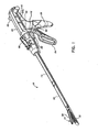
FIG. 1 is a perspective view of one preferred embodiment of the presently disclosed surgical stapling apparatus; -
FIG. 2 is a top view of the surgical apparatus shown inFIG. 1 ; -
FIG. 3 is a side view of the surgical apparatus shown inFIG. 1 ; -
FIG. 4 is a perspective view with parts separated of the handle assembly of the surgical apparatus shown inFIG. 1 ; -
FIG. 5 is a cross-sectional view of a portion of the firing lockout mechanism shown inFIG. 4 ; -
FIG. 6 is a perspective of the slide plate of the anti-reverse clutch mechanism of the surgical apparatus; -
FIG. 7 is an enlarged perspective view of the anti- reverse clutch mechanism shown inFIG. 1 ; -
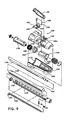
FIG. 8 is a side cross-sectional view of the surgical stapling apparatus shown inFIG. 1 in the non-actuated position with the disposable loading unit removed; -
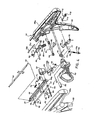
FIG. 9 is a perspective view with parts separated of the rotation member, the articulation mechanism, and the elongated body of the surgical stapling apparatus shown inFIG. 1 ; -
FIG. 10 is an enlarged view of the indicated area of detail shown inFIG. 8 ; -
FIG. 10a is a perspective view of the translation member of the articulating mechanism and the proximal end of the elongated body of the surgical stapling apparatus shown inFIG. 1 ; -
FIG. 10b is an enlarged cross-sectional view of the indicated area of detail ofFIG. 8 ; -
FIG. 10c is a cross-sectional view along section line 10c-10c ofFIG. 8 ; -
FIG. 11 is a perspective view of the cam member of the articulation mechanism of the surgical stapling apparatus shown inFIG. 1 ; -
FIG. 12 is a top view of the cam member of the articulation mechanism of the surgical stapling apparatus shown inFIG. 1 ; -
FIG. 12a is a perspective view of a non-articulating disposable loading unit usable with the surgical stapling apparatus shown inFIG. 1 ; -
FIG. 12b is a perspective view of the preferred articulating disposable loading unit of the surgical stapling apparatus shown inFIG. 1 ; -
FIG. 13 is a cross-sectional view taken alongsection line 13--13 ofFIG. 10 ; -
FIG. 14 is a cross-sectional view taken alongsection line 14--14 ofFIG. 10 ; -
FIG. 15 is a cross-sectional view taken alongsection line 15--15 ofFIG. 10 ; -
FIG. 16 is an enlarged view of the indicated area of detail shown inFIG. 8 ; -
FIG. 17 is a side perspective view of the blocking plate of the surgical stapling apparatus shown inFIG. 1 ; -
FIG. 18 is a top perspective view of the blocking plate of the surgical stapling apparatus shown inFIG. 1 ; -
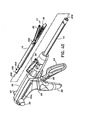
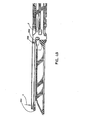
FIG. 19 is a perspective view of a disposable loading unit usable with the surgical stapling apparatus ofFIG. 1 ; -
FIG. 20 is another perspective view of a disposable loading unit usable with the surgical stapling apparatus ofFIG. 1 ; -
FIG. 21 is a perspective view of the tool assembly of the surgical stapling apparatus ofFIG. 1 with parts separated; -
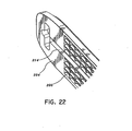
FIG. 22 is an enlarged perspective view of the distal end of the anvil assembly showing a plurality of staple deforming cavities; -
FIG. 23 is an enlarged perspective view of the distal end of the staple cartridge of the surgical stapling apparatus shown inFIG. 1 ; -
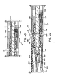
FIG. 24 is a side cross-sectional view taken alongsection line 24--24 ofFIG. 23 ; -
FIG. 25 is a bottom perspective view of the staple cartridge shown inFIG. 21 ; -
FIG. 26 is an enlarged perspective view of the actuation sled, the pushers and the fasteners shown inFIG. 21 ; -
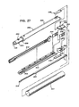
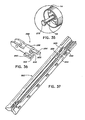
FIG. 27 is an enlarged perspective view with parts separated of the proximal housing portion and mounting assembly of the disposable loading unit shown inFIG. 19 ; -
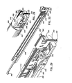
FIG. 28 is an enlarged perspective view of the mounting assembly of the disposable loading unit shown inFIG. 19 mounted to a distal end portion of the proximal housing portion; -
FIG. 29 is an enlarged perspective view of the proximal housing portion and the mounting assembly of the disposable loading unit shown inFIG. 19 with the upper housing half removed; -
FIG. 30 is a perspective view of the proximal housing portion and the mounting assembly of the disposable loading unit shown inFIG. 19 with the upper housing half removed; -
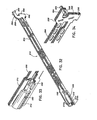
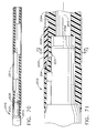
FIG. 31 is a perspective view with parts separated of the axial drive assembly; -
FIG. 32 is an enlarged perspective view of the axial drive assembly shown inFIG. 31 ; -
FIG. 33 is an enlarged perspective view of the proximal end of the axial drive assembly shown inFIG. 31 including the locking device; -
FIG. 34 is an enlarged perspective view of the distal end of the axial drive assembly shown inFIG. 31 ; -
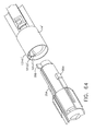
FIG. 35 is an enlarged perspective view of the distal end of the elongated body of the stapling apparatus shown inFIG. 1 ; -
FIG. 36 is an enlarged perspective view of the locking device shown inFIG. 33 ; -
FIG. 37 is an enlarged perspective view of a lower housing half of the proximal housing portion of the disposable loading unit shown inFIG. 27 ; -
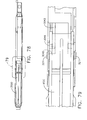
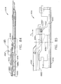
FIG. 38 is a side cross-sectional view of the disposable loading unit shown inFIG. 20 ; -
FIG. 39 is an enlarged view of the indicated area of detail shown inFIG. 38 ; -
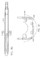
FIG. 40 is a perspective view of the surgical stapling apparatus shown inFIG. 1 with the disposable loading unit ofFIG. 19 detached from the elongated body; -
FIG. 41 is an enlarged perspective view of the disposable loading unit ofFIG. 19 during attachment to the elongated body of the surgical stapling apparatus shown inFIG. 1 ; -
FIG. 42 is another enlarged perspective view of the disposable loading unit ofFIG. 19 during attachment to the elongated body of the surgical stapling apparatus shown inFIG. 1 ; -
FIG. 43 is a cross-sectional view taken alongsection line 43--43 ofFIG. 41 ; -
FIG. 43a is a side cross-sectional view of the rotation knob, articulation mechanism, and sensing mechanism during insertion of a disposable loading unit into the elongated body of the surgical stapling apparatus; -
FIG. 44 is a cross-sectional view taken alongsection line 44--44 ofFIG. 42 ; -
FIG. 45 is a side cross-sectional view of the distal end of the disposable loading unit ofFIG. 1 with tissue positioned between the anvil and clamp assemblies; -
FIG. 46 is a side cross-sectional view of the handle assembly with the movable handle in an actuated position; -
FIG. 47 is an enlarged view of the indicated area of detail shown inFIG. 46 ; -
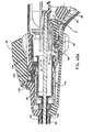
FIG. 48 is a cross-sectional view of the proximal end of the disposable loading unit ofFIG. 19 and the distal end of the elongated body of the surgical stapling apparatus shown inFIG. 1 with the control rod in a partially advanced position; -
FIG. 49 is a cross-sectional view of the tool assembly of the surgical stapling apparatus shown inFIG. 1 positioned about tissue in the clamped position; -
FIG. 50 is a cross-sectional view of the handle assembly of the stapling apparatus ofFIG. 1 during the clamping stroke of the apparatus; -
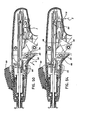
FIG. 51 is a side cross-sectional view of the distal end of the tool assembly of the stapling apparatus shown inFIG. 1 during firing of the apparatus; -
FIG. 52 is a side cross-sectional view of the distal end of the tool assembly of the stapling apparatus shown inFIG. 1 after firing of the apparatus; -
FIG. 53 is a side cross-sectional view of the handle assembly of the apparatus during retraction of the actuation shaft; -
FIG. 54 is a side cross-sectional view of the handle assembly of the stapling apparatus during actuation of the emergency release button; -
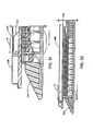
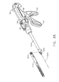
FIG. 55 is a top view of the articulation mechanism of the surgical stapling apparatus; -
FIG. 56 is a side cross-sectional view of the articulation mechanism and rotation member of the surgical stapling apparatus shown inFIG. 1 ; -
FIG. 57 is a top view of the distal end of the elongated body, the mounting assembly, and the proximal end of the tool assembly during articulation of the stapling apparatus; -
FIG. 58 is a perspective view of the surgical stapling apparatus during articulation of the tool assembly; -
FIG. 59 is a perspective view of the surgical stapling apparatus during articulation and rotation of the tool assembly; -
FIG. 60 is a top view of the distal end of the disposable loading unit immediately prior to articulation; -
FIG. 61 is a top view of the distal end of the elongated body, the mounting assembly, and the proximal end of the tool assembly during articulation of the stapling apparatus; -
FIG. 62 is a partial cross-sectional view of a portion of the disposable loading unit during retraction of the locking device; -
FIG. 63 is a partial cross-sectional view of a portion of the disposable loading unit with the locking device in the locked position; -
FIG. 64 is a partial perspective view of an elongated body and a disposable loading unit of an embodiment of a surgical stapling apparatus; -
FIG. 65 is a perspective view of an embodiment of a surgical stapling apparatus including an elongated body defining an axis and a disposable loading unit; -
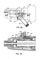
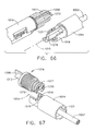
FIG. 66 is a perspective view of a connector portion of the disposable loading unit ofFIG. 65 and a connector portion of the elongated body ofFIG. 65 ; -
FIG. 67 is another perspective view of the connector portions ofFIG. 66 with additional components of the disposable loading unit removed; -
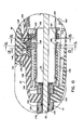
FIG. 68 is a cross-sectional perspective view of the connector portions ofFIG. 66 assembled together and retained in position by a threaded collar; -
FIG. 69 is a cross-sectional elevational view of the connector portions ofFIG. 66 and the threaded collar ofFIG. 68 ; -
FIG. 70 is a cross-sectional view of a connector portion of a disposable loading unit assembled to a connector portion of an elongated body of an alternative embodiment of a surgical stapling apparatus; -
FIG. 71 is a detail view of the connector portions ofFIG. 70 ; -
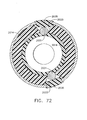
FIG. 72 is a cross-sectional view of the surgical stapling apparatus ofFIG. 70 taken along line 72-72 inFIG. 71 ; -
FIG. 73 is a detail view of an actuator of the elongated body ofFIG. 70 ; -
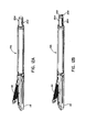
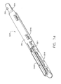
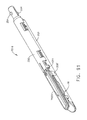
FIG. 74 is a perspective view of a disposable loading unit of an alternative embodiment of a surgical stapling apparatus; -
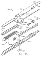
FIG. 75 is an exploded view of the disposable loading unit ofFIG. 74 ; -
FIG. 76 is a cross-sectional view of the disposable loading unit ofFIG. 74 including an anvil in an open position; -
FIG. 76A is a detail view of the disposable loading unit ofFIG. 74 illustrating an actuator operably engaged with the anvil; -
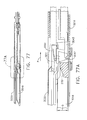
FIG. 77 is a cross-sectional view of the disposable loading unit ofFIG. 74 illustrating the anvil in a closed position; -
FIG. 77A is a detail view of the anvil and actuator of the disposable loading unit ofFIG. 76A ; -
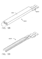
FIG. 78 is a plan view of the disposable loading unit ofFIG. 74 with some components removed; -
FIG. 79 is a detail view of a portion of the disposable loading unit ofFIG. 74 ; -
FIG. 80 is a bottom plan view of the disposable loading unit ofFIG. 74 ; -
FIG. 81 is a cross-sectional view of a staple cartridge carrier of the disposable loading unit ofFIG. 74 ; -
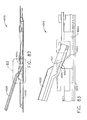
FIG. 82 is a cross-sectional elevational view of an alternative embodiment of a disposable loading unit with some components removed, the disposable loading unit including an anvil in an open position; -
FIG. 83 is a detail view of the disposable loading unit ofFIG. 82 including an actuator for closing the anvil; -
FIG. 84 is another cross-sectional elevational view of the disposable loading unit ofFIG. 82 illustrating the anvil in a closed position; -
FIG. 85 is a detail view of the actuator and the anvil ofFIG. 83 ; -
FIG. 86 is a perspective view of an anvil and an actuator of an alternative embodiment of a disposable loading unit; -
FIG. 87 is a perspective view of an actuator of a further alternative embodiment of a disposable loading unit; -
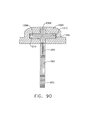
FIG. 88 is a perspective view of a drive beam of an alternative embodiment of a disposable loading unit; -
FIG. 89 is an end view of the drive beam ofFIG. 88 ; -
FIG. 90 is a cross-sectional view of a portion of the drive beam ofFIG. 88 positioned within a channel of an anvil; -
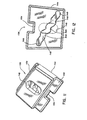
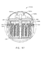
FIG. 91 is a perspective view of a disposable loading unit of an alternative embodiment of a surgical stapling apparatus; -
FIG. 92 is an end view of the disposable loading unit ofFIG. 91 ; -
FIG. 93 is a cross-sectional view of the disposable loading unit ofFIG. 91 ; -
FIG. 94 is a cross-sectional view of an alternative embodiment of a disposable loading unit; -
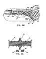
FIG. 95 is a cross-sectional view of a further alternative embodiment of a disposable loading unit; -
FIG. 96 is a cross-sectional view of another alternative embodiment of a disposable loading unit; -
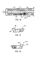
FIG. 97 is a cross-sectional view of an alternative embodiment of a disposable loading unit; -
FIG. 98 is a perspective view of an anvil assembly of an alternative embodiment of a disposable loading unit, the anvil assembly including an outer portion and an insert portion; -
FIG. 99 is a perspective view of the insert portion ofFIG. 98 ; -
FIG. 100 is a cross-sectional view of the insert positioned within the outer portion of the anvil assembly ofFIG. 98 ; -
FIG. 101 is a cross-sectional view of the anvil assembly ofFIG. 98 illustrating the outer portion after it has been deformed to retain the insert portion therein; -
FIG. 102 is a diagram of a piece of tubular stock having removed portions which are illustrated in dash; -
FIG. 103 is a cross-sectional view of an anvil formed from the tubular stock ofFIG. 102 ; -
FIG. 104 is a cross-sectional view of an anvil assembly of an alternative embodiment of a disposable loading unit, the anvil assembly including an inner portion press-fit within an outer portion; -
FIG. 105 is an end view of the inner portion ofFIG. 104 ; -
FIG. 106 is a cross-sectional view of an anvil assembly of an alternative embodiment of a disposable loading unit, the anvil assembly including a body and a support plate attached thereto; -
FIG. 107 is a cross-sectional view of the anvil body ofFIG. 106 ; -
FIG. 108 is a cross-sectional view of the support plate ofFIG. 106 ; -
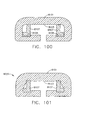
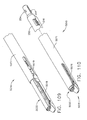
FIG. 109 is a perspective view of an alternative embodiment of a disposable loading unit including an anvil in a closed position and a sleeve in a retracted position; -
FIG. 110 is a perspective view of the disposable loading unit ofFIG. 109 illustrating the sleeve in an extended position to support the anvil; -
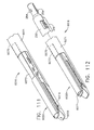
FIG. 111 is a perspective view of an alternative embodiment of a disposable loading unit including an anvil in a closed position and a tongue in a retracted position; -
FIG. 112 is a perspective view of the disposable loading unit ofFIG. 111 illustrating the tongue in an extended position to support the anvil; -
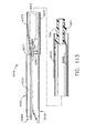
FIG. 113 is a cross-sectional view of the disposable loading unit ofFIG. 111 ; -
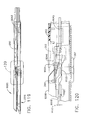
FIG. 114 is an exploded view of an alternative embodiment of a disposable loading unit; -
FIG. 115 is a cross-sectional view of the disposable loading unit ofFIG. 114 illustrating an anvil in an open position; -
FIG. 116 is a detail view of the disposable loading unit ofFIG. 114 ; -
FIG. 117 is a cross-sectional view of the disposable loading unit ofFIG. 114 illustrating the anvil in a closed position; -
FIG. 118 is a detail view of the disposable loading unit ofFIG. 116 ; -
FIG. 119 is a cross-sectional view of the disposable loading unit ofFIG. 114 illustrating the anvil in a collapsed position; -
FIG. 120 is a detail view of the disposable loading unit ofFIG. 114 ; -
FIG. 121 is a cross-sectional view of the disposable loading unit ofFIG. 114 illustrating the anvil in its collapsed position; -
FIG. 122 is a cross-sectional view of the disposable loading unit ofFIG. 114 illustrating the anvil returned to its closed position; -
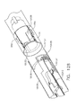
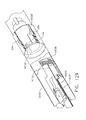
FIG. 123 is a perspective view of an alternative embodiment of a disposable loading unit; -
FIG. 124 is a perspective view of a knife lockout of the disposable loading unit ofFIG. 123 ; -
FIG. 125 is a perspective view of the disposable loading unit ofFIG. 123 with some components removed and a connector portion of an elongated body of a surgical stapling apparatus; -
FIG. 126 is another perspective view of the disposable loading unit ofFIG. 123 ; -
FIG. 127 is another perspective view of the disposable loading unit ofFIG. 123 with some components of the elongated body connector portion removed; -
FIG. 128 is a perspective view of the disposable loading unit ofFIG. 123 prior to a drive beam of the surgical apparatus being advanced within the disposable loading unit and a retention plate engaged with a biasing spring; -
FIG. 129 is a perspective view of the disposable loading unit ofFIG. 123 after the drive beam has been advanced the retention plate has been disengaged from the biasing spring; -
FIG. 130 is a perspective view of the disposable loading unit ofFIG. 123 after it has been disengaged from the connector portion of the elongated body illustrating the knife lockout biased into a locked-out position by the biasing spring; -
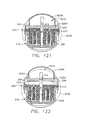
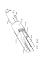
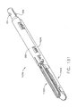
FIG. 131 is a perspective view of an alternative embodiment of a disposable loading unit; -
FIG. 132 is an exploded view of the disposable loading unit ofFIG. 131 illustrating a removable staple cartridge; -
FIG. 133 is an elevational view of the disposable loading unit ofFIG. 131 ; -
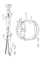
FIG. 134 is an end view of the disposable loading unit ofFIG. 131 ; and -
FIG. 135 is another end view of the disposable loading unit ofFIG. 131 illustrating an anvil in an open position. - Preferred embodiments of the presently disclosed endoscopic surgical stapling apparatus will now be described in detail with reference to the drawings, in which like reference numerals designate identical or corresponding elements in each of the several views. Those of ordinary skill in the art will understand that the devices and methods specifically described herein and illustrated in the accompanying drawings are non-limiting exemplary embodiments and that the scope of the various embodiments of the present invention is defined solely by the claims. The features illustrated or described in connection with one exemplary embodiment may be combined with the features of other embodiments. Such modifications and variations are intended to be included within the scope of the present invention.
- In the drawings and in the description that follows, the term "proximal", as is traditional, will refer to the end of the stapling apparatus which is closest to the operator, while the term distal will refer to the end of the apparatus which is furthest from the operator.
-
FIGS. 1-3 illustrate one embodiment of the presently disclosed surgical stapling apparatus shown generally as 10. Briefly,surgical stapling apparatus 10 includes ahandle assembly 12 and anelongated body 14. A disposable loading unit orDLU 16 is releasably secured to a distal end ofelongated body 14.Disposable loading unit 16 includes atool assembly 17 having acartridge assembly 18 housing a plurality of surgical staples and ananvil assembly 20 movably secured in relation tocartridge assembly 18.Disposable loading unit 16 is configured to apply linear rows of staples measuring from about 30 mm to about 60 mm in length. Disposable loading units having linear rows of staples of other lengths are also envisioned, e.g., 45 mm. Handleassembly 12 includes astationary handle member 22, amovable handle member 24, and abarrel portion 26. Arotatable member 28 is preferably mounted on the forward end ofbarrel portion 26 to facilitate rotation ofelongated body 14 with respect to handleassembly 12. Anarticulation lever 30 is also preferably mounted on the forward end ofbarrel portion 26 adjacentrotatable knob 28 to facilitate articulation oftool assembly 17. A pair of retraction knobs 32 are movably positioned alongbarrel portion 26 to returnsurgical stapling apparatus 10 to a retracted position, as will be described in detail below. - Referring to
FIG. 4 , handleassembly 12 includeshousing 36, which is preferably formed from molded housing half-sections 36a and 36b, which formsstationary handle member 22 andbarrel portion 26 of handle assembly 12 (SeeFIG. 1 ).Movable handle member 24 is pivotably supported between housing half-sections 36a and 36b aboutpivot pin 38. A biasingmember 40, which is preferably a torsion spring, biasesmovable handle 24 away fromstationary handle 22. Anactuation shaft 46 is supported withinbarrel portion 26 ofhousing 36 and includes atoothed rack 48. A drivingpawl 42 having arack engagement finger 43 with laterally extendingwings 43a and 43b is pivotably mounted to one end ofmovable handle 24 about apivot pin 44. A biasingmember 50, which is also preferably a torsion spring, is positioned to urgeengagement finger 43 of drivingpawl 42 towardstoothed rack 48 ofactuation shaft 46.Movable handle 24 is pivotable to moveengagement finger 43 of drivingpawl 42 into contact withtoothed rack 48 ofactuation shaft 46 to advance the actuation shaft linearly in the distal direction. The forward end ofactuation shaft 46 rotatably receives theproximal end 49 of acontrol rod 52 such that linear advancement ofactuation shaft 46 causes corresponding linear advancement ofcontrol rod 52. A lockingpawl 54 having a rack engagement member 55 is pivotably mounted withinhousing 36 aboutpivot pin 57 and is biased towardstoothed rack 48 by biasingmember 56, which is also preferably a torsion spring. Engagement member 55 of lockingpawl 54 is movable into engagement withtoothed rack 48 to retainactuation shaft 46 in a longitudinally fixed position. - A
retraction mechanism 58 which includes a pair of retractor knobs 32 (SeeFIG. 1 ) is connected to the proximal end ofactuation shaft 46 by acoupling rod 60. Couplingrod 60 includes right and leftengagement portions 62a and 62b for receivingretractor knobs 32 and acentral portion 62c which is dimensioned and configured to translate within a pair oflongitudinal slots 34a formed inactuation shaft 46 adjacent the proximal end thereof. Arelease plate 64 is operatively associated withactuation shaft 46 and is mounted for movement with respect thereto in response to manipulation of retractor knobs 32. A pair of spaced apart pins 66 extend outwardly from a lateral face ofactuation shaft 46 to engage a pair of correspondingangled cam slots 68 formed inrelease plate 64. Upon rearward movement of retractor knobs 32, pins 66 can releaseplate 64 downwardly with respect toactuation shaft 46 and with respect totoothed rack 48 such that the bottom portion ofrelease plate 64 extends belowtoothed rack 48 to disengageengagement finger 43 of drivingpawl 42 fromtoothed rack 48. A transverse slot 70 is formed at the proximal end ofrelease plate 64 to accommodate thecentral portion 62c ofcoupling rod 60, and elongated slots 34 (SeeFIG. 1 ) are defined in thebarrel section 26 ofhandle assembly 12 to accommodate the longitudinal translation ofcoupling rod 60 as retraction knobs 32 are pulled rearwardly to retractactuation shaft 46 and thus retractcontrol rod 52 rearwardly.Actuation shaft 46 is biased proximally byspring 72 which is secured at one end to coupling rod portion 62 viaconnector 74 and at the other end to post 76 onactuation shaft 46. - Referring also to
FIG. 5 , handleassembly 12 includes afiring lockout assembly 80 which includes aplunger 82 and apivotable locking member 83.Plunger 82 is biased to a central position by biasingsprings 84 and includes annular tapered camming surfaces 85. Each end ofplunger 82 extends through housing 36 (SeeFIG. 1 ) adjacent an upper end ofstationary handle 22.Pivotable locking member 83 is pivotably attached at its distal end between housing half-sections 36a and 36b aboutpivot pin 86 and includes a lockingsurface 88 andproximal extension 90 having aslot 89 formed therein. Lockingmember 83 is biased byspring 92 counter-clockwise (as viewed inFIG. 4 ) to move lockingsurface 88 to a position to abut the distal end ofactuation shaft 46 to prevent advancement ofshaft 46 and subsequent firing of staplingapparatus 10. Annular taperedcamming surface 85 is positioned to extend into taperedslot 89 inproximal extension 90. Lateral movement ofplunger 82 in either direction against the bias of eitherspring 84 moves taperedcamming surface 85 into engagement with the sidewalls of taperedslot 89 to pivot lockingmember 83 clockwise aboutpivot pin 86, as viewed inFIG. 4 , to move blockingsurface 88 to a position to permit advancement ofactuation shaft 46 and thus firing of staplingapparatus 10. Blockingsurface 88 is retained in this position byrecesses 87 which receive the tapered tip ofcamming surface 85 to lock lockingmember 83 in a counter-clockwise position. Operation of firinglockout assembly 80 will be further illustrated below. - Referring to
FIGS. 4 ,6, and 7 , handlemechanism 12 also includes an anti-reverse clutch mechanism which includes afirst gear 94 rotatably mounted on afirst shaft 96, andsecond gear 98 mounted on asecond shaft 100, and a slide plate 102 (FIGS. 6 and 7 ) slidably mounted withinhousing 36.Slide plate 102 includes anelongated slot 104 dimensioned and configured to be slidably positioned about lockingpawl pivot pin 57, agear plate 106 configured to mesh with the teeth ofsecond gear 98, and acam surface 108. In the retracted position,cam surface 108 ofslide plate 102 engages lockingpawl 54 to prevent lockingpawl 54 from engagingtoothed rack 48.Actuation shaft 46 includes a distal set of gear teeth 110a spaced from a proximal set ofgear teeth 110b positioned to engagefirst gear 94 ofactuation shaft 46 during movement ofactuation shaft 46. Whenactuation shaft 46 is advanced by pivotingmovable handle 24 aboutpivot pin 38, distal gear teeth 110a onactuation shaft 46 mesh with and rotatefirst gear 94 andfirst shaft 96.First shaft 96 is connected tosecond shaft 100 by spring clutch assembly such that rotation offirst shaft 96 will cause corresponding rotation ofsecond shaft 100. Rotation ofsecond shaft 100 causes corresponding rotation ofsecond gear 98 which is engaged withgear plate 106 onslide plate 102 to cause linear advancement ofslide plate 102. Linear advancement ofslide plate 102 is limited to the length ofelongated slot 104. When slide plate has been advanced the length ofslot 104,cam surface 108releases locking pawl 54 such that it is moved into engagement withtoothed rack 48. Continued advancement ofactuation shaft 46 eventually movesgear teeth 110b into engagement withgear plate 106. However, sinceslide plate 102 is longitudinally fixed in position, the spring clutch is forced to release, such that continued distal advancement ofactuation shaft 46 is permitted. - When
actuation shaft 46 is returned to the retracted position (by pullingretraction knobs 34 proximally, as discussed above)gear teeth 110b engagefirst gear 94 to rotatesecond gear 98 in the reverse direction to retractslide member 102 proximally withinhousing 36. Proximal movement ofslide member 102 advancescam surface 108 into lockingpawl 54 prior to engagement between lockingpawl 54 andtoothed rack 48 to urge lockingpawl 54 to a position to permit retraction ofactuation shaft 46. - Referring again to
FIG. 4 , handleassembly 12 includes anemergency return button 112 pivotally mounted withinhousing 36 about apivot member 114 supported between housing half-sections 36a and 36b.Return button 112 includes an externally positionedmember 116 positioned on the proximal end ofbarrel portion 26.Member 116 is movable aboutpivot member 114 into engagement with the proximal end of lockingpawl 54 to urge rack engagement member 55 out of engagement withtoothed rack 48 to permit retraction ofactuation shaft 46 during the firing stroke of thestapling apparatus 10. As discussed above, during the clamping portion of advancement ofactuation shaft 46,slide plate 102 disengages pawl 54 fromrack 48 and thus actuation ofreturn button 112 is not necessary to retract theactuation shaft 46. -
FIG. 8 illustrates the interconnection ofelongated body 14 and handleassembly 12. Referring toFIGS. 8-10 ,housing 36 includes anannular channel 117 configured to receive anannular rib 118 formed on the proximal end ofrotation member 28, which is preferably formed from molded half-sections 28a and 28b.Annular channel 117 andrib 118 permit relative rotation betweenrotation member 28 andhousing 36.Elongated body 14 includesinner housing 122 and anouter casing 124.Inner housing 122 is dimensioned to be received withinouter casing 124 and includes an internal bore 126 (FIG. 8 ) which extends therethrough and is dimensioned to slidably receive afirst articulation link 123 andcontrol rod 52. The proximal end ofhousing 122 andcasing 124 each include a pair of diametricallyopposed openings radial projections 132 formed on the distal end ofrotation member 28.Projections 132 andopenings secure rotation member 28 andelongated body 14 in relation to each other, both longitudinally and rotatably. Rotation ofrotation knob 28 with respect to handleassembly 12 thus results in corresponding rotation ofelongated body 14 with respect to handleassembly 12. - An
articulation mechanism 120 is supported onrotatable member 28 and includesarticulation lever 30, acam member 136, atranslation member 138, and first articulation link 123 (FIG. 9 ).Articulation lever 30 is pivotably mounted aboutpivot member 140 which extends outwardly fromrotation member 28 and is preferably formed integrally therewith. Aprojection 142 extends downwardly fromarticulation lever 30 for engagement withcam member 136. - Referring temporarily to
FIGS. 11 and 12 ,cam member 136 includes ahousing 144 having anelongated slot 146 extending through one side thereof and a steppedcamming surface 148 formed in the other side thereof. Each step ofcamming surface 148 corresponds to a particular degree of articulation of staplingapparatus 10. Although five steps are illustrated, fewer or more steps may be provided.Elongated slot 146 is configured to receiveprojection 142 formed onarticulation lever 30.Housing 144 includes a distal steppedportion 150 and a proximal steppedportion 152. Proximal steppedportion 152 includes arecess 154. - Referring again to
FIGS. 8-10 and also toFIGS. 13-15 ,translation member 138 includes a plurality ofridges 156 which are configured to be slidably received withingrooves 158 formed along the inner walls ofrotation member 28. Engagement betweenridges 156 andgrooves 158 prevent relative rotation ofrotation member 28 andtranslation member 138 while permitting relative linear movement. The distal end oftranslation member 138 includesarm 160 which includes anopening 162 configured to receive afinger 164 extending from the proximal end of articulation link 123 (SeeFIG. 10a ). Apin 166 having ahousing 168 constructed from a non-abrasive material, e.g., Teflon, is secured totranslation member 138 and dimensioned to be received within steppedcamming surface 148. - In an assembled condition, proximal and distal stepped
portions cam member 136 are positioned beneathflanges rotation member 28 to restrictcam member 136 to transverse movement with respect to the longitudinal axis of staplingapparatus 10. Whenarticulation lever 30 is pivoted aboutpivot member 140,cam member 136 is moved transversely onrotation member 28 to move steppedcamming surface 148 transversely relative to pin 166, forcingpin 166 to move proximally or distally along steppedcam surface 148. Sincepin 166 is fixedly attached totranslation member 138,translation member 138 is moved proximally or distally to effect corresponding proximal or distal movement offirst actuation link 123. - Referring to
FIGS. 8-10 and 16 , a disposable loading unit sensing mechanism extends within staplingapparatus 10 fromelongated body 14 intohandle assembly 12. The sensing mechanism includes asensor tube 176 which is slidably supported withinbore 26 ofelongated body 14. The distal end ofsensor tube 176 is positioned towards the distal end ofelongated body 14 and the proximal end ofsensor tube 176 is secured within the distal end of asensor cylinder 176 via a pair ofnubs 180. The distal end of asensor link 182 is secured to the proximal end ofsensor cylinder 178. Sensor link 182 (SeeFIGS. 8a and 8c ) has abulbous end 184 which engages acamming surface 83a onpivotable locking member 83. When a disposable loading unit (not shown) is inserted in the distal end ofelongated body 14, the disposable loading unit engages the distal end 177 ofsensor tube 176 to drivesensor tube 176 proximally, and thereby drivesensor cylinder 178 andsensor link 182 proximally. Movement ofsensor link 182 proximally causesbulbous end 184 ofsensor link 182 to move distally ofcamming surface 83a to allow lockingmember 83 to pivot under the bias ofspring 92 from a position permitting firing of staplingapparatus 10 to a blocking position, wherein blockingmember 83 is positioned to engageactuation shaft 46 and prevent firing of staplingapparatus 10.Sensor link 182 and lockingmember 83 function to prevent firing ofsurgical stapling apparatus 10 after a disposable loading unit has been secured toelongated body 14, without first operatingfiring lockout assembly 80. It is noted that movement oflink 182 proximallypermits locking member 83 to move to its position shown inFIG. 5 . - Referring again to
FIGS. 9-12 ,cam member 136 includesrecess 154. A lockingring 184 having anub portion 186 configured to be received withinrecess 154 is positioned aboutsensor cylinder 178 between acontrol tab portion 188 and aproximal flange portion 190. Aspring 192 positioned betweenflange portion 190 and lockingring 184 urges locking ring distally aboutsensor cylinder 178. When an articulating disposable loading unit 16b having an extendedinsertion tip 193 is inserted into the distal end ofelongated body 14 of staplingapparatus 10,insertion tip 193causes tab portion 188 to move proximally into engagement with lockingring 184 to urge lockingring 184 andnub 186 proximally ofrecess 154 in cam member 136 (SeeFIG. 12b ). Withnub 186 positioned proximally ofrecess 154,cam member 136 is free to move transversely to effect articulation of staplingapparatus 10. A non-articulating disposable loading unit does not have an extended insertion tip (SeeFIG. 12a ). As such, when a non-articulating disposable loading unit is inserted inelongated body 14,sensor cylinder 178 is not retracted proximally a sufficient distance to move nub 186 fromrecess 154. Thus,cam member 136 is prevented from moving transversely by nub 186 of lockingring 184 which is positioned inrecess 154 andarticulation lever 30 is locked in its central position. - Referring to
FIGS. 16-18 , the distal end ofelongated body 14 includes a controlrod locking mechanism 190 which is activated during insertion of a disposable loading unit intoelongated body 14. Controlrod locking mechanism 190 includes a blockingplate 192 which is biased distally by aspring 194 and includes aproximal finger 189 having angledcam surface 195. Asemi-circular engagement member 196 is biased transversely towardscontrol rod 52 by aspring 197.Control rod 52 includes anannular recess 199 configured to receiveengagement member 196. Blockingplate 192 is movable from a distal position spaced fromengagement member 196 to a proximal position located behindengagement member 196. In the proximal position,engagement member 196 is prevented from being biased fromrecess 199 by engagement with blockingplate 192. During insertion of a disposable loading unit 16 (SeeFIG. 1 ) into the distal end ofelongated body 14, as will be described in further detail below,cam surface 195 of blockingplate 192 is engaged by a nub 254 (FIG. 30 ) on thedisposable loading unit 16 as the disposable loading unit is rotated into engagement withelongated body 14 to urgeplate 192 to the proximal position.Engagement member 196, which is positioned withinrecess 199, is retained therein by blockingplate 192 while nub 254 engagescam surface 195 to prevent longitudinal movement ofcontrol rod 52 during assembly. When thedisposable loading unit 16 is properly positioned with respect to theelongated body 14,nub 254 on the proximal end of thedisposable loading unit 16 passes offcam surface 195 allowingspring 194 to return blockingplate 192 to its distal position to permit subsequent longitudinal movement ofcontrol rod 52. It is noted that when the disposable loading unit nub passes offcam surface 195, an audible clicking sound is produced indicating that thedisposable loading unit 16 is properly fastened to theelongated body 14. - Referring to
FIGS. 19 and 20 ,disposable loading unit 16 includes aproximal housing portion 200 adapted to releasably engage the distal end of body portion 14 (FIG. 1 ). A mountingassembly 202 is pivotally secured to the distal end ofhousing portion 200, and is configured to receive the proximal end oftool assembly 17 such that pivotal movement of mountingassembly 202 about an axis perpendicular to the longitudinal axis ofhousing portion 200 effects articulation oftool assembly 17. - Referring to
FIGS. 21-26 ,tool assembly 17 preferably includesanvil assembly 20 andcartridge assembly 18.Anvil assembly 20 includesanvil portion 204 having a plurality of staple deforming concavities 206 (FIG. 22 ) and acover plate 208 secured to a top surface ofanvil portion 204 to define a cavity 210 (FIG. 24 ) therebetween.Cover plate 208 is provided to prevent pinching of tissue during clamping and firing of staplingapparatus 10.Cavity 210 is dimensioned to receive a distal end of an axial drive assembly 212 (SeeFIG. 27 ). Alongitudinal slot 214 extends throughanvil portion 204 to facilitate passage ofretention flange 284 ofaxial drive assembly 212 into theanvil cavity 210. Acamming surface 209 formed onanvil portion 204 is positioned to engageaxial drive assembly 212 to facilitate clamping oftissue 198. A pair ofpivot members 211 formed onanvil portion 204 are positioned withinslots 213 formed incarrier 216 to guide the anvil portion between the open and clamped positions. A pair of stabilizing members 215 engage arespective shoulder 217 formed oncarrier 216 to preventanvil portion 204 from sliding axially relative tostaple cartridge 220 ascamming surface 209 is deformed. -
Cartridge assembly 18 includes acarrier 216 which defines anelongated support channel 218.Elongated support channel 218 is dimensioned and configured to receive astaple cartridge 220. Correspondingtabs 222 andslots 224 formed alongstaple cartridge 220 andelongated support channel 218 function to retainstaple cartridge 220 withinsupport channel 218. A pair of support struts 223 formed onstaple cartridge 220 are positioned to rest on side walls ofcarrier 216 to further stabilizestaple cartridge 220 withinsupport channel 218. -
Staple cartridge 220 includesretention slots 225 for receiving a plurality offasteners 226 andpushers 228. A plurality of spaced apartlongitudinal slots 230 extend throughstaple cartridge 220 to accommodateupstanding cam wedges 232 ofactuation sled 234. A centrallongitudinal slot 282 extends along the length ofstaple cartridge 220 to facilitate passage of aknife blade 280. During operation ofsurgical stapler 10,actuation sled 234 translates throughlongitudinal slots 230 ofstaple cartridge 220 to advancecam wedges 232 into sequential contact withpushers 228, to causepushers 228 to translate vertically withinslots 224 andurge fasteners 226 fromslots 224 into thestaple deforming cavities 206 ofanvil assembly 20. - Referring to
FIGS. 27 and28 , mountingassembly 202 includes upper and lower mountingportions bore 240 on each side thereof dimensioned to receive threaded bolts 242 (SeeFIG. 21 ) for securing the proximal end ofcarrier 216 thereto. A pair of centrally located pivot members 244 (SeeFIG. 21 ) extends between upper and lower mounting portions via a pair ofcoupling members 246 which engage the distal end ofhousing portion 200. Couplingmembers 246 each include an interlocking proximal portion 248 configured to be received ingrooves 250 formed in the proximal end ofhousing portion 200 to retain mountingassembly 202 andhousing portion 200 in a longitudinally fixed position in relation thereto. -
Housing portion 200 ofdisposable loading unit 16 includes anupper housing half 250 and alower housing half 252 contained within anouter casing 251. The proximal end ofhousing half 250 includesengagement nubs 254 for releasably engagingelongated body 14 and aninsertion tip 193.Nubs 254 form a bayonet type coupling with the distal end ofbody 14 which will be discussed in further detail below. Housing halves 250 and 252 define achannel 253 for slidably receivingaxial drive assembly 212. Asecond articulation link 256 is dimensioned to be slidably positioned within aslot 258 formed betweenhousing halves plates 254 are positioned adjacent the distal end ofhousing portion 200 adjacent the distal end ofaxial drive assembly 212 to prevent outward bulging ofdrive assembly 212 during articulation oftool assembly 17. - Referring to
FIGS. 29-30 ,second articulation link 256 includes at least one elongated metallic plate. Preferably, two or more metallic plates are stacked to formlink 256. The proximal end ofarticulation link 256 includes ahook portion 258 configured to engage first articulation link 123 (SeeFIG. 9 ) and the distal end includes aloop 260 dimensioned to engage aprojection 262 formed on mountingassembly 202.Projection 262 is laterally offset frompivot pin 244 such that linear movement ofsecond articulation link 256causes mounting assembly 202 to pivot about pivot pins 244 to articulatetool assembly 17. - Referring also to
FIGS. 31-34 ,axial drive assembly 212 includes anelongated drive beam 266 including adistal working head 268 and aproximal engagement section 270.Drive beam 266 may be constructed from a single sheet of material or, preferably, multiple stacked sheets.Engagement section 270 includes a pair ofengagement fingers corresponding retention slots 272a and 272b formed indrive member 272.Drive member 272 includes aproximal porthole 274 configured to receive thedistal end 276 of control rod 52 (SeeFIG. 35 ) when the proximal end ofdisposable loading unit 16 is engaged withelongated body 14 ofsurgical stapling apparatus 10. - The distal end of
drive beam 266 is defined by avertical support strut 278 which supports aknife blade 280, and anabutment surface 283 which engages the central portion ofactuation sled 234 during a stapling procedure.Surface 285 at the base ofsurface 283 is configured to receive asupport member 287 slidably positioned along the bottom of thestaple cartridge 220.Knife blade 280 is positioned to translate slightly behindactuation sled 234 through a centrallongitudinal slot 282 in staple cartridge 220 (FIG. 30 ) to form an incision between rows of stapled body tissue. Aretention flange 284 projects distally fromvertical strut 278 and supports acylindrical cam roller 286 at its distal end.Cam roller 286 is dimensioned and configured to engagecam surface 209 onanvil body 204 to clampanvil portion 204 against body tissue. - Referring also to
FIGS. 36-39 , alocking device 288 is pivotally secured to drivemember 270 about apivot pin 290. Lockingdevice 288 includes a pair ofelongate glides channel 296. Aweb 298 joins a portion of the upper surfaces ofglides elongated slot 298 formed indrive beam 266 at a position distal ofdrive member 270.Horizontal cams 300 and 302 extend fromglides lower housing half 252. As best shown inFIG. 42 , atorsion spring 304 is positionedadjacent drive member 270 and engageshorizontal cams 300 and 302 of lockingdevice 288 to normally bias lockingdevice 288 downward towardlower housing half 252 ontoledge 310. Lockingdevice 288 translates throughhousing portion 200 withaxial drive assembly 212. Operation of lockingdevice 288 will be described below. - Referring to
FIGS. 40-44 , to use staplinginstrument 10, adisposable loading unit 16 is first secured to the distal end ofelongated body 14. As discussed above, staplinginstrument 10 can be used with articulating and non-articulating disposable loading units having linear rows of staples between about 30 mm and about 60 mm. To securedisposable loading unit 16 toelongated body 14, thedistal end 276 ofcontrol rod 52 is inserted intoinsertion tip 193 ofdisposable loading unit 16, andinsertion tip 193 is slid longitudinally into the distal end ofelongated body 14 in the direction indicated by arrow "A" inFIG. 41 such thathook portion 258 ofsecond articulation link 256 slides within achannel 310 inelongated body 314.Nubs 254 will each be aligned in a respective channel (not shown) inelongated body 14. Whenhook portion 258 engages theproximal wall 312 ofchannel 310,disposable loading unit 16 is rotated in the direction indicated by arrow "B" inFIGS. 41-44 to movehook portion 258 ofsecond articulation link 256 into engagement withfinger 164 offirst articulation link 123.Nubs 254 also forms a bayonet type coupling withinannular channel 314 inbody 14. During rotation ofloading unit 16,nubs 254 engage cam surface 195 (FIG. 41 ) ofblock plate 192 to initially moveplate 192 in the direction indicated by arrow "C" inFIGS. 41 and43 to lockengagement member 196 inrecess 199 ofcontrol rod 52 to prevent longitudinal movement ofcontrol rod 52 during attachment ofdisposable loading unit 16. During the final degree of rotation,nubs 254 disengage fromcam surface 195 to allow blockingplate 192 to move in the direction indicated by arrow "D" inFIGS. 42 and44 from behindengagement member 196 to once again permit longitudinal movement ofcontrol rod 52. - Referring to
FIGS. 43 and43a , wheninsertion tip 193 engages the distal end ofsensor tube 176, the disposable loading unit sensing mechanism is actuated.Insertion tip 193 engages and movessensor tube 176 proximally in the direction indicated by arrow "E" inFIG. 43 . As discussed above, proximal movement ofsensor tube 176 effects proximal movement ofsensor cylinder 178 andsensor link 182 in the direction indicated by arrow "E" inFIG. 43a to pivot lockingmember 83 counter-clockwise, as indicated by arrow "Y" inFIG. 43a , from a non-blocking position to a position blocking movement ofactuation shaft 46. - Referring to
FIGS. 46-49 , with a disposable loading unit attached to staplinginstrument 10,tool assembly 17 can be positioned about tissue 320 (FIG. 45 ). To clamp tissue betweenanvil assembly 20 andcartridge assembly 18,stationary handle 24 is moved in the direction indicated by arrow "E" inFIG. 46 against the bias oftorsion spring 40 to move drivingpawl 42 into engagement withshoulder 322 onactuation shaft 46. Engagement betweenshoulder 322 and drivingpawl 42advances actuation shaft 46 and thus advancescontrol rod 52 distally.Control rod 52 is connected at its distal end to axial drive assembly 212 (FIG. 48 ), includingdrive beam 266, such that distal movement ofcontrol rod 52 effects distal movement ofdrive beam 266 in the direction indicated by arrow "F" inFIGS. 48 and49 , movingcam roller 286 into engagement withcam surface 209 onanvil portion 204 to urgeanvil portion 204 in the direction indicated by arrow "G" inFIG. 49 . It is noted that one complete stroke ofmovable handle 24advances actuation shaft 46 approximately 15 mm which is sufficient to clamp tissue during the first stroke but not to fire staples. - As discussed above with respect to the anti-reverse clutch mechanism, during the first (clamping) stroke of
movable handle 24, slide plate 102 (FIG. 46 ) prevents lockingpawl 54 from engagingtoothed rack 48. To maintainactuation shaft 46 in its longitudinal position afterhandle 24 is released, an engagement member 324 (FIG. 47 ) is provided on lockingmember 83 to engageshoulder 326 onactuation shaft 46 and retainshaft 46 in its longitudinal position (SeeFIG. 47 ). Upon release ofmovable handle 24,drive pawl 42 moves overrack 48 astorsion spring 40 returns handle 24 to a position spaced fromstationary handle 22. In this position, drivingpawl 42 is urged into engagement withtoothed rack 48 to retainactuation shaft 46 in its longitudinal fixed position. - In order to fire staples,
movable handle 24 is actuated again, i.e., moved through another stroke. As discussed above, staplingapparatus 10 is capable of receiving disposable loading units having linear rows of staples of between about 30 mm and about 60 mm. Since each stroke of themovable handle 24 preferably advancesactuation shaft 46 15 mm, and one stroke is required to clamp tissue, the movable handle must be actuated (n+1) strokes to fire staples, where n is the length of the linear rows of staples in the disposable loading unit attached to staplinginstrument 10 divided by 15 mm. - Referring to
FIG. 50 , prior to being able to fire staples, firing lockout assembly 80 (FIG. 4 ) must be actuated to move lockingsurface 88 from its blocking position (FIG. 47 ) to a non-blocking position. This is accomplished by pressing down onplunger 82 to movecamming surface 85 into engagement with sidewalls ofslot 89 of lockingmember 83 to pivot lockingmember 83 in the direction indicated by arrow "G" inFIG. 50 (see alsoFIG. 5 ). Thereafter,movable handle 24 may be actuated an appropriate number of strokes to advanceactuation shaft 46, and thuscontrol rod 52 anddrive beam 266, distally in the direction indicated by arrow "H" inFIGS. 51 and 52 to advanceactuation sled 234 throughstaple cartridge 220 to effect ejection of staples. It is noted that after the first or clamping stroke of movable handle 54 (during the second stroke), slide 102 passes over lockingpawl 54 allowingtorsion spring 56 to move lockingpawl 54 in the direction indicated by arrow "I" inFIG. 50 into engagement withtoothed rack 48 to retainactuation shaft 46 in its longitudinal position. - Referring to
FIG. 53 , to retractactuation shaft 46 and thuscontrol rod 52 anddrive member 266 after firing staples, retraction knobs 32 (seeFIG. 1 ) are pulled proximally causingpins 66 to moverelease plate 64 in the direction indicated by arrow "J" inFIG. 53 overteeth 48 to disengagedrive pawl 42 from engagement withteeth 48. As discussed above, with respect to the anti-reverse clutch mechanism, lockingpawl 54 is urged byslide plate 102 out of engagement with toothed rack 48 (not shown) to permitactuation shaft 46 to be moved proximally, in the direction indicated by arrow "L", afterdrive pawl 42 is disengaged fromteeth 48. - Referring to
FIG. 54 , in order to retractactuation shaft 46 prior to firing stapling apparatus, i.e., when locking pawl is currently engaged with toothed racked 48,emergency return button 112 is pushed in the direction indicated by arrow "Z" inFIG. 54 to disengage lockingpawl 54 fromtoothed rack 48. Retraction knobs 32 (FIG. 1 ) must also be concurrently pulled rearwardly, as discussed above, to releasedrive pawl 42 fromrack 48. - Referring to
FIGS. 55-61 , when an articulating disposable loading unit is secured toelongated body 14 andarticulation lever 30 is pivoted in the direction indicated by arrow "M" inFIG. 55 ,cam member 136 is moved transversely by projection 142 (FIG. 10 ) in the direction indicated by arrow "N" betweenflanges rotation knob 28. Sincetranslation member 138 is prevented from rotating by ridges 156 (FIG. 13 ),pin 166, which is fixedly secured totranslation member 138, is forced to move along steppedcam surface 148. Movement ofpin 166 causes corresponding movement oftranslation member 138 in the direction indicated by arrow "P" inFIGS. 55 and 56 to advancefirst articulation link 123 in the distal direction. The distal end offirst articulation link 123 engages the proximal end of second articulation link 256 (FIG. 42 ) which is connected toprojection 262 on mountingassembly 202 to advancesecond link 256 in the direction indicated by arrow "Q" inFIG. 57 .Projection 262 is laterally offset frompivot members 244, such that distal advancement ofsecond articulation link 256causes mounting assembly 202 and thustool assembly 17 to pivot in the direction indicated by arrow "R" inFIGS. 57 and58 . Note inFIG. 59 thatrotation member 28 can be rotated to rotateelongated body 14 about its longitudinal axis whiletool assembly 17 is articulated. -
FIGS. 60-61 illustrate articulation oftool assembly 17 in the opposite direction to that described above. Whensecond articulation link 256 is retracted by rotatingarticulation lever 30 in a counter-clockwise direction (not shown) as viewed inFIG. 55 ,pin 66 is forced to move proximally along steppedcamming surface 148, movingtranslation member 138 andfirst articulation link 123 proximally. Movement offirst articulation link 123 proximally, causessecond articulation link 256 to move proximally as indicated by arrow "S" inFIG. 58 , to rotatetool assembly 17 in a clockwise direction, as indicated by arrow "T" inFIG. 61 . - Referring to
FIG. 12 , movement of pin 166 (FIG. 9 ) betweenadjacent step portions 340causes tool assembly 17 to articulate 22.5 degrees.Camming surface 148 includes fivestep portions 340. The third step portion corresponds to the non-articulated tool assembly position, whereas the first and the fifth step portions correspond to articulation oftool assembly 17 to forty-five degrees. Each step portion is flat to retainarticulation lever 30 in a fixed position whenpin 166 is engaged therewith. - Referring now to
FIGS. 37 ,39 ,62 and 63 , the sequence of lockout operation will be described in detail. InFIG. 39 ,lockout device 288 is shown in its prefired position withhorizontal cams 300 and 302 resting on top ofprojections 330 formed in the sidewalls of lower housing half 252 (FIG. 37 ). In this position, lockingdevice 288 is held up out of alignment withprojection 332 formed in the bottom surface oflower housing half 252, andweb 298 is in longitudinal juxtaposition withshelf 334 defined indrive beam 266. This configuration permits the anvil 20 (FIG. 38 ) to be opened and repositioned onto the tissue to be stapled until the surgeon is satisfied with the position without activatinglocking device 288 to disable thedisposable loading unit 16. - As shown in
FIG. 62 , upon distal movement ofdrive beam 266, lockingdevice 288 rides off of projections 330 (not shown) and is biased into engagement with baselower housing half 252 byspring 304, distal toprojection 332. Lockingdevice 288 remains in this configuration throughout firing of the apparatus. - Upon retraction of the
drive beam 266 in the direction indicated by arrow "U" inFIG. 62 , lockingdevice 288 passes underprojections 330 and rides overprojection 332 until the distalmost portion of lockingdevice 288 is proximal toprojection 332.Spring 304biases locking device 288 into juxtaposed alignment withprojection 332, effectively disabling the disposable loading unit. If an attempt is made to reactuate the apparatus, thecontrol rod 52 will abut a proximal end surface of lockingdevice 288 which surface is diagonally sloped to impart a moment aboutpivot pin 342 such that the distal end of lockingdevice 288 is rotationally urged into contact withprojection 332. Continued distal force in the direction indicated by arrow "W" inFIG. 63 , will only serve to increase the moment applied to the locking device thus the locking device will abutprojection 332 and inhibit distal movement of thecontrol rod 52. - Referring again to
FIGS. 41-44 , the disabled or locked disposable loading unit can be removed from the distal end ofelongated body 14 by rotatingdisposable loading unit 16 in the direction opposite to the direction indicated by arrow "B" inFIGS. 41, 42 and44 , to disengagehook portion 258 of second articulation link 256 fromfinger 164 offirst articulation link 123, and to disengagenubs 254 from withinchannel 314 ofelongated body 14. After rotation,disposable loading unit 16 can be slid in the direction opposite to that indicated by arrow "A" inFIG. 41 to detachbody 14 fromdisposable loading unit 16. Subsequently, additional articulating and/or non-articulating disposable loading units can be secured to the distal end of elongated body, as described above, to perform additional surgical stapling and/or cutting procedures. As discussed above, each disposable loading unit may include linear rows of staples which vary from about 30 mm to about 60 mm. - Although the above-described surgical stapling instruments may be suitable for their intended purpose, improvements to these instruments are provided below. As described above, surgical stapling instruments can include a handle portion, an elongated body, or shaft, and a disposable loading unit, wherein the disposable loading unit can be removably attached to the elongated body. As described above in connection with
disposable loading unit 16 illustrated inFIGS. 40-42 ,elongated body 14 of the surgical stapling instrument can define an axis along whichdisposable loading unit 16 can be assembled thereto. In various circumstances, though,disposable loading unit 16 can become unintentionally detached fromelongated body 14 causing the surgical stapling instrument to malfunction or be rendered inoperable. Such circumstances can particularly arise when the disposable loading unit becomes detached and separated from the elongated body along the axis defined by the elongated body, i.e., the axis along which the disposable loading unit was assembled to the elongated body. In various embodiments of the present invention, a disposable loading unit can be assembled to an elongated body of a surgical instrument in a direction which is not collinear with or parallel to the elongated body axis. In at least one embodiment, referring toFIG. 65 ,disposable loading unit 1016 can be assembled toelongated body 1014 in a direction which is transverse, perpendicular, or oblique toaxis 1015 defined byelongated body 1014. - In various embodiments, referring to
FIGS. 66 and 67 ,disposable loading unit 1016 can includeconnector portion 1017 which can be configured to be engaged withconnector portion 1019 ofelongated body 1014. In at least one embodiment,connector portion 1017 can include at least one projection and/or groove which can be mated with at least one projection and/or groove ofconnector portion 1019. In at least one such embodiment, the connector portions can include co-operating dovetail portions. In various embodiments, the connector portions can be configured to interlock with one another and prevent, or at least inhibit, distal and/or proximal movement ofdisposable loading unit 1016 alongaxis 1015. In at least one embodiment, similar to the devices described above, the surgical stapling instrument can includecontrol rod 1052 which can be operably connected to drivemember 1212 ofdisposable loading unit 1016 such thatdrive member 1212 can be advanced distally to deploy staples therefrom and/or incise tissue, for example, upon an actuation of handle member 24 (FIG.1 ). In at least one such embodiment,drive member 1212 can includeaperture 1272 which can be configured to receiveprojection 1276 extending fromcontrol rod 1052. In various embodiments, such an arrangement can allowdisposable loading unit 1016 to be assembled toelongated member 1014 in a direction which is not collinear with or parallel toaxis 1015. Although not illustrated,drive member 1212 andcontrol rod 1052 can include any other suitable arrangement of projections and apertures to operably connect them to each other. Also similar to the devices described above, the surgical instrument can includefirst articulation link 1123 which can be operably engaged withsecond articulation link 1256 such that the operation of articulation lever 1030 can be transmitted todisposable loading unit 1016. - In various embodiments, further to the above, the projections and/or grooves of
connector portions disposable loading unit 1016 from moving in a direction which is transverse toaxis 1015. In at least one embodiment, referring primarily toFIGS. 68 and 69 , a sleeve, or collar, can be utilized to retain the disposable loading unit to the elongated member. In various embodiments,collar 1021 can be threadably engaged with threadedportion 1023 ofdisposable loading unit 1016 to preventconnector portions collar 1021 can includeaperture 1025 having, first, a threadedportion 1027 which can threadably engage threadedportion 1023 and, second, asecond portion 1029 which can closely receiveelongated member 1014 so as to prevent, or at least limit, relative movement betweendisposable loading unit 1016 and elongatedmember 1014. Alternatively, although not illustrated, a collar can be configured to threadably engageelongated member 1014 and closely receivedisposable loading unit 1016. In at least one embodiment, a collar can be configured to threadably engage both the elongated member and the disposable loading unit. - In various embodiments, a detent mechanism can be utilized to retain a disposable loading unit to an elongated member of a surgical stapling instrument. In at least one embodiment, referring to
FIGS. 70-72 , elongatedmember 2014 can include at least oneball detent 2031 which can be configured to engagedisposable loading unit 2016 and holddisposable loading unit 2016 in position. In various embodiments, elongated member can include at least oneaperture 2033 for receivingball detents 2031 and at least oneretention member 2035 for retainingball detents 2031 inapertures 2033. In at least one embodiment,retention members 2035 can also be configured to biasball detents 2031 into recesses 2037 indisposable loading unit 2016 such that the movement ofdisposable loading unit 2016 alongaxis 2015 can be prevented, or at least inhibited. In use,insertion tip 2193 ofdisposable loading unit 2016 can be inserted into elongatedmember 2014 such that the end ofdisposable loading unit 2016 can contactball detents 2031 and displace them radially withinapertures 2033. Oncedisposable loading unit 2016 has been inserted to its proper depth, recesses 2037 can be substantially aligned withapertures 2033 andretention members 2035 can position at least a portion of ball detents within recesses 2037. - In various embodiments, further to the above, at least one of
retention members 2035 can be comprised of a resilient material. In at least one embodiment,ball detents 2031 andretention members 2035 can be structured and arranged such thatretention members 2035 are deflected outwardly byball detents 2031 and, as a result,resilient members 2035 can apply a biasing force toball detents 2031. In order to releasedisposable loading unit 2016 fromelongated member 2014, elongatedmember 2016 can further includeactuator 2039 which can be manipulated to retractretention members 2035 proximally such that undercut 2041 ofresilient members 2035 can be aligned, or at least substantially aligned, withball detents 2031. In various embodiments, the alignment of undercut 2041 withball detents 2031 can allowball detents 2031 to be displaced radially and out of engagement with recesses 2037 whendisposable loading unit 2016 is pulled out of the aperture inelongated member 2014. In at least one embodiment, referring toFIGS. 70 and73 , elongatedmember 2014 can further includereturn spring 2043 which can be configured to advanceactuator 2039 andretention members 2035 distally and repositionretention members 2035 relative toball detents 2031. In various embodiments, as illustrated inFIGS. 71 and72 ,ball detents 2031 can be spherical, or at least substantially spherical, and can be comprised of any suitable material such as stainless steel, for example. In other various embodiments, although not illustrated,detents 2031 can have any suitable non-spherical shape. - In various embodiments, a disposable loading unit and an elongated member of a surgical instrument can include co-operating snap-fit features for retaining the disposable loading unit to the surgical stapling instrument. In at least one embodiment, although not illustrated, a disposable loading unit can include arms extending therefrom which can be at least partially received within apertures or recess in an elongated assembly. In use, the arms can be configured to flex inwardly toward each other as they are inserted into the elongated member and then resiliently spring outwardly when the arms are aligned with the apertures. In various embodiments, the surgical instrument can include a lock which can be slid intermediate the arms to hold the arms in the apertures and prevent, or at least inhibit, the disposable loading unit from becoming detached from the surgical instrument. In at least one embodiment, the lock could be slid distally upon an actuation of a trigger. In various alternative embodiments, the lock can include one or more cams configured to engage the arms and retain them in the apertures when the lock is rotated.
- After a disposable loading unit has been attached to a surgical stapling instrument, the instrument can be positioned relative to the soft tissue of a patient. In various circumstances, a surgical stapling instrument can include an anvil and a staple cartridge, where the anvil can be rotated relative to the staple cartridge to position the anvil and the staple cartridge with respect to the soft tissue. As described above in connection with
disposable loading unit 16 illustrated inFIGS. 38 and40 ,disposable loading unit 16 can includeanvil assembly 20 andcartridge assembly 18, whereanvil assembly 20 can be pivoted between an open and closed positions. In some such devices, as outlined above and referring toFIG. 24 ,axial drive assembly 212 can be configured to contactcamming surface 209 ofanvil assembly 20 and moveanvil assembly 20 into a closed position upon a first actuation ofmovable handle 24. Upon subsequent actuations ofmovable handle 24,drive assembly 212 can be advanced throughdisposable loading unit 16 to clamp, staple, and incise the soft tissue positionedintermediate cartridge assembly 18 andanvil assembly 20. In such instruments, as a result of the tissue being clamped at the same time as it is being stapled and incised, a portion of the soft tissue can flow, or 'milk', out of the distal end of the disposable loading unit and, in various circumstances, the soft tissue may not be properly treated by the surgical stapling instrument. - In various embodiments of the present invention, such problems can be ameliorated by utilizing a surgical stapling instrument which can apply a clamping force to soft tissue prior to the staples being deployed from the staple cartridge and/or the drive assembly being advanced within the disposable loading unit. In various circumstances, such embodiments can prevent, or at least inhibit, the soft tissue from milking out of the distal end of the disposable loading unit. In at least one embodiment, a surgical stapling instrument can include an actuator configured to be retracted relative to the distal end of the disposable loading unit to rotate the anvil between an open position and a closed position and clamp the tissue in position. In at least one such embodiment, referring to
FIGS. 74-81 ,disposable loading unit 3016 can includecartridge assembly 3018 andanvil assembly 3020, whereanvil assembly 3020 can be rotated towardcartridge assembly 3018 byactuator 3043. In at least one embodiment,anvil assembly 3020 can include, first, at least onepivot tab 3211 which can be rotatably received within an aperture or recess withinstaple cartridge assembly 3018, for example, and, second, at least onerecess 3047 which can be configured to operably receive at least a portion ofactuator 3043. When actuator 3043 is pulled in a direction indicated by arrow "P", in at least one embodiment,actuator 3043 can rotateanvil assembly 3020 into a closed position about an axis defined bypivot tabs 3211 and apply a clamping force to the soft tissue. - In various embodiments, as outlined above,
actuator 3043 can include at least oneprojection 3049 which can be configured to engage the sidewalls ofrecess 3047 and apply a force toanvil assembly 3020. In at least one embodiment, such a force can generate a torque, or force-moment, causinganvil assembly 3020 to rotate aboutpivot tabs 3211 between an open position, as illustrated inFIG. 76 , and a closed position, as illustrated inFIG. 77 . In use, as also outlined above, such a torque can apply a clamping pressure or force to tissue positionedintermediate anvil assembly 3020 andstaple cartridge assembly 3018. In various embodiments, the torque applied toanvil assembly 3020 can be directly proportional to the force applied byactuator 3043 and the distance betweenprojections 3049 andpivot tabs 3211, i.e., distance "D" (FIG. 77 ). In at least one embodiment, a disposable loading unit can be designed such that distance D can be maximized, or at least substantially increased, to apply a larger clamping moment or force to the soft tissue. In at least one such embodiment, referring toFIGS. 80 and 81 ,staple cartridge assembly 3018 can comprisestaple cartridge carrier 3216 which can include apertures, or recesses, 3045 which can be configured to allow at least a portion ofprojections 3049 to extend therethrough such that the distance betweenprojections 3049 andpivot tabs 3211 can be increased. - In various embodiments, referring to
FIG. 75 ,disposable loading unit 3016 can includespring 3051 which can configured to biasanvil assembly 3020 into an open position and, in addition, a spring which can bias actuator 3043 into its most distal position. In use, as outlined above,actuator 3043 can be pulled proximally to pivotanvil assembly 3020 into its closed position. In such circumstances, as illustrated inFIG. 77A ,anvil assembly 3020 can resiliently compressspring 3051 such thatspring 3051 can returnanvil assembly 3020 to its open position whenactuator 3043 is released as described in greater detail below. In various embodiments, a surgical instrument can include a trigger, or any other suitable actuation device, which can be manipulated by a surgeon, or other clinician, to pullactuator 3043 proximally and, in at least one embodiment,lock actuator 3043 in its retracted position. In at least one embodiment, referring generally toFIGS. 1 and9 ,actuator 3043 can be operably engaged witharticulation lever 30 andfirst articulation link 123 such that, whenarticulation lever 30 is rotated in a first direction,articulation link 123 andactuator 3043 can be retracted proximally. Similarly, whenarticulation lever 30 is rotated in a second direction,articulation link 123 andactuator 3043 can be advanced distally. In various embodiments,actuator 3043 can be advanced distally to removeprojections 3049 fromrecesses 3047 and allowspring 3051 to returnanvil assembly 3020 to its open position. - In various embodiments, a disposable loading unit can include an actuator comprising a cam configured to operably engage an anvil of the disposable loading unit and apply a compressive pressure or force to soft tissue prior to staples being deployed into the soft tissue. In at least one embodiment, referring to
FIGS. 82 and 83 ,disposable loading unit 4016 can includeanvil assembly 4020,staple cartridge assembly 4018, andactuator 4043, whereactuator 4043 can be configured to rotateanvil assembly 4020 between an open position, as illustrated inFIG. 82 , and a closed position, as illustrated inFIG. 84 . In various embodiments, referring toFIGS. 82 and84 ,actuator 4043 can includecam 4053 whereactuator 4043 can be pulled proximally, i.e., in a direction indicated by arrow "P", such thatcam 4053 can engageanvil assembly 4020 and rotateanvil assembly 4020 about an axis defined bypivot tabs 4211. Similar to the above,actuator 4043 can be operable engaged with any suitable trigger, such asarticulation lever 30, for example, to motivateactuator 4043. - In various embodiments, an actuator cam can include at least one of a linear, non-linear, arcuate, and/or curvilinear profile. In at least one embodiment,
cam 4053 can include an arcuateprofile having apex 4055 andinitial contact point 4057, for example, wherecam 4053 can be configured to engageanvil assembly 4020 such thatinitial contact point 4057 firstcontacts anvil assembly 4020. Asactuator 4043 is pulled further proximally,cam 4053 can slide relative toanvil assembly 4020 such that various other points ofcam 4053contact anvil assembly 4020 until apex 4055 is in contact withanvil assembly 4020 as illustrated inFIG. 85 . At such point,anvil assembly 4020 can be in its closed position. In various embodiments, referring again toFIG. 85 , apex 4055 can be positioned proximally relative to pivottabs 4211, i.e., on the proximal side ofaxis 4059 and, as a result,anvil assembly 4020 can be prevented from rotating back into its open position untilcam 4053 is disengaged from, i.e., moved distally relative to,anvil assembly 4020. Furthermore, the position of apex 4055 relative to pivottabs 4211 can utilize leverage, or mechanical advantage, to apply an even greater clamping force to the soft tissue. - In various embodiments, as
cam 4053 is retracted proximally andanvil assembly 4020 is rotated into its closed position as described above,anvil assembly 4020 can contact soft tissue, for example, positionedintermediate anvil assembly 4020 andstaple cartridge assembly 4018. In at least one embodiment,anvil assembly 4020 can apply an initial clamping force to the soft tissue when it initially contacts the tissue and whereinanvil assembly 4020 can apply an increasingly greater force to the soft tissue asanvil assembly 4020 is moved into its final, or closed, position. In various embodiments, the clamping force can be increased in a substantially linear manner. In at least one embodiment, a cam, such ascam 4053, for example, can be configured to driveanvil 4020 in such a manner as to increase the clamping force to the soft tissue in a non-linear manner. In at least one such embodiment, the clamping force can be increased in a geometric manner such that the climax of the clamping force is applied to the soft tissue whenanvil assembly 4020 is in its final, or closed, position, for example. As a result of the above, an anvil can apply a clamping force to soft tissue prior to staples being deployed from the staple cartridge, for example, and prevent, or at least inhibit, the soft tissue from flowing, or 'milking', out of the distal end of the disposable loading unit. - In various embodiments, further to the above, a cam can include a profile which utilizes a variable mechanical advantage as the anvil is moved into its closed position. In at least one embodiment, the cam can include a compound profile which includes a first portion for utilizing a first mechanical advantage, or leverage, during the initial movement of the anvil and, in addition, a second portion for utilizing a second mechanical advantage, or leverage, for subsequent movement of the anvil. In at least one such embodiment, a larger mechanical advantage can be utilized during the final movement of the anvil so as to apply a larger clamping force to the soft tissue when the anvil is in its closed position.
- In various embodiments, referring to
FIGS. 84 and 85 ,anvil assembly 4020 can include a tissue-contacting surface, such assurface 4063, for example, which can be positioned parallel to, or at least substantially parallel to, a tissue-contacting surface onstaple cartridge assembly 4018, such assurface 4065, for example, whenanvil assembly 4020 is in its closed position. In at least one embodiment,anvil assembly 4020 andstaple cartridge assembly 4018 can be configured such that there is a gap defined betweenanvil assembly 4020 andstaple cartridge assembly 4018 whenanvil assembly 4020 is in its closed position. In various embodiments, the distance between tissue-contactingsurfaces distal end 4069 of the disposable loading unit as compared toproximal end 4067. In at least one such embodiment, as a result, the distal end ofanvil assembly 4020 can trap soft tissue within the disposable loading unit whenanvil assembly 4020 is moved into its closed position. In other various embodiments, the gap between tissue-contactingsurfaces proximal end 4067 anddistal end 4069. - In various embodiments, referring to
FIG. 86 , an actuator, such as actuator 4043', for example, can include two ormore cams 4053 which can be configured to engage at least a portion ofanvil assembly 4020 as described above. In at least one embodiment,cams 4053 can extend from a shaft portion 4061' of actuator 4043' such thatcams 4053 can be moved relative toanvil assembly 4020 simultaneously. In various embodiments, actuator 4043' can also include at least onehook portion 258 configured to engagefirst articulation link 123 as outlined further above. In various alternative embodiments, referring toFIG. 87 , a disposable loading unit can include two or more actuators, such asactuators 4043", for example, which can each include one ormore cams 4053, for example, for pivotinganvil assembly 4020. In at least one such embodiment, each actuator 4043" can include ahook portion 258 which can be operably connected with one or more articulation links, for example, in a surgical stapling instrument. - In various embodiments of the present invention, a surgical stapling instrument can include a disposable loading unit comprising a staple cartridge, an anvil, and a sleeve, wherein the sleeve can be configured to be slid relative to the staple cartridge and the anvil and hold at least one of the anvil and the staple cartridge in position. In at least one embodiment, referring to
FIGS. 109 and 110 ,disposable loading unit 5016 can include at least one sleeve or collar, such assleeve 5071, for example, which can be slid between a proximal position, as illustrated inFIG. 109 , and a distal position, as illustrated inFIG. 110 . In at least one embodiment,sleeve 5071 can include an aperture which, whensleeve 5071 is positioned in its distal position, for example, can at least partially encompass or surroundanvil assembly 5020 and/orstaple cartridge assembly 5018. In various embodiments,sleeve 5071 can be configured to preventanvil assembly 5020 from prematurely opening. Furthermore,sleeve 5071 can prevent, or at least inhibit,anvil assembly 5020 andstaple cartridge assembly 5018 from deflecting when the soft tissue positioned therebetween is stapled and/or incised. - In at least one embodiment,
sleeve 5071, for example, can be configured to apply a clamping pressure or force to the soft tissue positioned betweenanvil assembly 5020 andstaple cartridge assembly 5018. In various embodiments, similar to the above, such a clamping pressure or force can be applied before surgical staples are deployed from the staple cartridge and/or the soft tissue is incised. In various embodiments, referring again toFIGS. 109 and 110 ,sleeve 5071 can further includeslots 5079 which can be configured such that, whensleeve 5071 is advanced distally,sleeve 5071 may not contact and/or damage the tissue positioned betweenanvil assembly 5020 andstaple cartridge assembly 5018. - In various embodiments, a surgical stapling instrument can include a cantilever, or tongue, configured to be slid relative to at least one of a staple cartridge and an anvil and engage at least one of the staple cartridge and anvil to hold them in a closed position, for example. In at least one embodiment, referring to
FIGS. 111 and 112 ,disposable loading unit 6016 can include at least one sleeve or collar, such assleeve 6071, for example, which can be slid between a proximal position, as illustrated inFIG. 111 , and a distal position, as illustrated inFIG. 112 . In at least one embodiment,sleeve 6071 can includetongue 6073 extending therefrom which can be configured to engage at least a portion ofanvil assembly 6020 and apply a force thereto. In various embodiments, such a force can positionanvil assembly 6020 against the soft tissue positionedintermediate anvil assembly 6020 andstaple cartridge assembly 6018 and clamp the soft tissue therebetween. Referring toFIG. 113 ,tongue 6073, for example, can comprise any suitable configuration including an arcuate, linear, and/or curvi-linear configuration. In at least one embodiment,tongue 6073 can include a curved body comprisingproximal end 6075 connected tosleeve 6071 and adistal tip 6077 which can be configured to engageanvil assembly 6020 withinanvil cavity 6210. In at least one such embodiment, the force transmitted betweentongue 6073 andanvil assembly 6020 can be applied toanvil assembly 6020 throughtip 6077 and, as a result, the location in which the force is applied to the soft tissue can be dictated by the position oftip 6077. - In various embodiments,
sleeve 6071 can be configured such that it can be advanced between its proximal and distal positions prior to staples being deployed fromstaple cartridge assembly 6018 and the tissue being incised bydrive member 6212, for example. In at least one such embodiment, referring toFIG. 113 ,tongue 6073 can be slid distally bysleeve 6071 untildistal tip 6077 oftongue 6073contacts anvil assembly 6020 atdistal end 6069. Thereafter, similar to the above,drive assembly 6212 can be advanced toward the distal end of the disposable loading unit to staple and/or incise the tissue. In such circumstances, the clamping force applied to the soft tissue bytongue 6073 can be applied at the distal end of the disposable loading unit and the possibility that the tissue may milk out of the distal end of the disposable loading unit can be reduced. In other various embodiments,distal tip 6077 can be advanced towarddistal end 6069 asdrive member 6212 is advanced towarddistal end 6069, for example. In at least one embodiment,distal tip 6077 can be configured to contactanvil assembly 6020 at a location which is positioned directly over, or at least adjacent to,knife blade 6280. In such embodiments,tongue 6073 can supportanvil assembly 6020 directly above the location in which staples are deformed againstanvil assembly 6020. - After an anvil of a disposable loading unit has been moved into a closed position, as outlined above, a drive beam can be advanced within the disposable loading unit to eject the staples therefrom and/or incise soft tissue. In various embodiments, a drive beam, such as
drive beam 266, for example, can be comprised of a single sheet of material and/or multiple stacked sheets of material. As also outlined above, a drive assembly, such asdrive assembly 212, for example, can further comprise acam roller 286 and asupport member 287 which can be configured to retain drive beam toanvil assembly 20 andstaple cartridge assembly 18, respectively. In various circumstances, the time and cost to assemble such components to drivebeam 266 can be significant. In various embodiments of the present invention, such time and cost can be reduced. More particularly, in at least one embodiment of the present invention, a portion of a drive beam can be deformed, or otherwise integrally formed, so as to create features which can obviate the need for a separately-manufacturedcam roller 286 and/orsupport member 287, for example. In various embodiments, referring toFIGS. 88-90 ,drive beam 1266 can includeintegral cam members 1286 which can extend laterally fromretention flange 1284. In at least one embodiment,drive beam 1266 can manufactured from a flat, or at least substantially flat, piece of material where the piece of material can be stamped such thatcam members 1286 are at least partially separated fromretention flange 1284 and extend in a transverse or oblique direction with respect to drivebeam 1266. In at least one such embodiment, referring toFIG. 90 ,cam members 1286 can be sized and configured such that they can slide withinanvil channel 1210 and at least assist in holdinganvil assembly 1020 in a closed position. In addition to or in lieu of the above, although not illustrated, a portion ofdrive beam 1266, for example, can be configured to extend laterally fromdrive beam 1266 so as to retaindrive assembly 1212 to a staple cartridge assembly. In at least one embodiment, similar to the above, retention flanges can be at least partially separated fromdrive beam 1266 during a stamping process such that the integral retention flanges extend in a transverse or oblique direction with respect to drivebeam 1266. In various embodiments, as a result of the above, at least one integral cam member and/or at least one integral retention member can be formed during a suitable manufacturing process, such as progression stamping, for example, which can reduce, or even eliminate, the assembly time of additional components to the drive beam. - In various embodiments, referring to
FIG. 49 , the anvil of a disposable loading unit can include a slot defined therein which can be configured to receive at least a portion of a drive beam. In at least one embodiment, referring toFIGS. 51 and 52 , the anvil can include a channel extending therethrough wherecam rollers 286 can be configured to engage a sidewall of the channel and apply a force, or forces, to the anvil assembly. In various circumstances, such forces can cause the anvil to elastically and/or plastically deform and, as a result, affect the deployment of the surgical staples into the soft tissue. In various embodiments of the present invention, an anvil can include features which can eliminate, or at least reduce, the deformation of the anvil. In at least one embodiment, an anvil can include a first member having staple pockets for deforming the staples, a first cover plate secured to the first member, and a second cover plate secured to at least one of the first member and the first cover plate, wherein the first and second cover plates can be configured to support the first member. In at least one such embodiment, referring toFIGS. 91-93 ,disposable loading unit 7016 can includeanvil assembly 7020 which can compriseanvil portion 204,first cover plate 208 affixed toanvil portion 204, andsecond cover plate 7081 affixed to at least one ofanvil portion 204 andfirst cover plate 208. In various embodiments,first cover plate 208 can be welded toanvil portion 204 and, in addition,second cover plate 7081 can be welded tofirst cover plate 208 and/oranvil portion 204. In at least one embodiment,second cover plate 7081 can strengthen, stiffen, and/or increase the section modulus of the anvil assembly, thereby reducing the possibility that the anvil assembly may unsuitably deform during use. - In various embodiments, referring to
FIG. 91 ,first cover plate 208 can include tissue stops 208' extending therefrom. In at least one embodiment, tissue stops 208' can be configured such that, when the anvil and staple cartridge assemblies are positioned relative to soft tissue, tissue stops 208' can prevent, or at least inhibit, the soft tissue from progressing past a certain point in the disposable loading unit. In various embodiments of the present invention, referring toFIG. 94 ,second cover plate 7081a ofdisposable loading unit 7016a can include tissue stops 7081' extending therefrom in addition to or in lieu of the above. In various embodiments, a disposable loading unit can include a second cover plate which can be formed from one or more sheets of material. In at least one embodiment, referring toFIG. 95 , disposable loading unit 7061b can includesecond cover plate 7081b, whereinsecond cover plate 7081b can be formed from a single sheet of material, such as stainless steel, for example. In various embodiments, the sheet of material can be deformed over one or more forming anvils, or mandrels, until it is bent into a suitable shape. In at least one embodiment, the sheet of material can include one ormore side edges 7083b which can be positioned against or proximal tocentral portion 7085b ofsecond cover plate 7081b during the bending process. Thereafter, in at least one such embodiment, side edges 7083b can be affixed tocentral portion 7085b by any suitable manufacturing process, such as welding, for example. As a result of the above, in various embodiments,second cover plate 7081b can include at least one tissue-contactingedge 7087b which is formed at the bend between two portions of the sheet material. In at least one such embodiment, the tissue-contactingedges 7087b can have a rounded or radiused profile which can be configured such that the edges do not damage soft tissue. In various embodiments, further to the above, an anvil can be formed from a sheet of material wherein the formed anvil can include a central portion having a first side and a second side and at least two flaps oppositely folded to one another with one flap on the first side and one flap on the second side. - In various embodiments, referring to
Fig. 95 ,first cover plate 208 andanvil member 204 can defineanvil cavity 210 therebetween. In at least one embodiment, as described above,cavity 210 can be configured to receivecam actuators 286 and, in various circumstances,first cover plate 208 can be configured such that there are large gaps betweencam actuators 286 and the sidewalls ofcavity 210. In such an embodiment, however, the configuration offirst cover plate 208 may not be optimized so as to maximize the moment of inertia of the anvil assembly with respect toaxis 7089b, for example. As known in the art, a device having a larger moment of inertia with respect to an axis can be more resistant to bending or deformation with respect to that axis. Thus, in various embodiments of the present invention, a cover plate of an anvil assembly can be configured such that the gaps betweencam actuators 286 and the cover plate can be eliminated, or at least reduced. In at least one embodiment, referring toFIG. 96 ,first cover plate 7208c can include at least onebase portion 7093c and at least oneside wall 7095c positioned adjacent to, or in abutting contact with,cam actuators 286. In such embodiments,side walls 7095c can extend in a direction so as to increase the moment of inertia offirst cover plate 7208c with respect toaxis 7089b. In various embodiments,side wall portions 7095c can be oriented in perpendicular, or at least substantially perpendicular, directions with respect tobase portions 7093c. - In various embodiments, further to the above, an anvil assembly can include a first and/or second cover plate which can include ribs and/or folds therein which can strengthen or stiffen the anvil assembly. In at least one embodiment, referring to
FIG. 97 , an anvil assembly ofdisposable loading unit 7016d can includeanvil portion 204 andcover plate 7208d attached toanvil portion 204. In various embodiments,cover plate 7208d can be include ribs or folds 7097d which can increase the moment of inertia ofcover plate 7208d with respect toaxis 7089b. In at least one embodiment,cover plate 7208d can be manufactured from one or more sheets of material, such as stainless steel, for example, where the sheet, or sheets, can be bent into the configuration illustrated inFig. 97 . As known in the art, the moment of inertia of a cross-section can be increased by increasing the mass of the cross-section and/or increasing the distance between a mass and a reference axis. The ribs and/orfolds 7097d, as they can add additional mass at a distance fromaxis 7089b, can add to the moment of inertia ofcover plate 7208d as compared to coverplate 208, for example. - In various embodiments, as described above, two or more components of an anvil assembly can be welded together. In at least one embodiment of the present invention, two or more components of an anvil assembly can be press-fit together such that the components are retained to one another. In various embodiments, referring to
FIGS. 98-101 ,anvil assembly 8020 can includeinsert portion 8099 andcover portion 8101 where, referring toFIGS. 98 and100 ,insert portion 8099 can be positioned withincavity 8103 defined bycover portion 8101. Thereafter, referring toFIG. 101 , at least a portion ofcover portion 8101 can be deformed, stamped, or swaged such that at least a portion ofinsert portion 8099 is captured withincavity 8103. In at least one embodiment,insert portion 8099 can include uneven, rough, and/or corrugated surfaces which can be configured to interlock with portions ofcover portion 8101 when it is deformed. - In various embodiments, referring to
FIG. 100 ,cavity 8103 can include slots orgrooves 8105 which can be configured to slidably receivetines 8107 ofinsert portion 8099 therein, whereincover portion 8101 can be deformed to capture tines, or arms, 8107 ingrooves 8105. In at least one embodiment,arms 8107 can be press-fit intogrooves 8105 where, in various circumstances, such a press-fit can be sufficient to retaininsert portion 8099 withincover portion 8101. In various embodiments, the cover and insert portions of the anvil assembly can be constructed from the same material or different materials. In at least one embodiment, the cover portion can be comprised of a softer or more malleable material than the insert portion. In at least one such embodiment, the cover portion can be at least partially comprised of aluminum, for example, and the insert portion can be at least partially comprised of steel, for example. In either event, the cover portion can be comprised of a material which can be stamped or coined to form the staple-deforming pockets therein. In at least one such embodiment, the cover portion can then be anodized. - In various embodiments, as described above, an anvil assembly can comprise an anvil portion have staple-deforming pockets therein and a cover plate for supporting the anvil portion. In at least one embodiment, the anvil portion and the cover plate can be integrally formed. Referring to
FIGS. 102-103 ,anvil 8020a can be manufactured from a tube, or annulus, of material where, in at least one embodiment, at least a portion of the tube, such asportion 8109a, for example, can be removed. In at least one such embodiment, the remaining portion of the tube, such asportion 8111a, for example, can be deformed utilizing a stamping or forming process such thatanvil 8020a can include co-planar, or at least substantially co-planar,anvil portions 8204a extending fromsupport portion 8208a. In various embodiments, the tube can be at least partially comprised of extruded aluminum and, in at least one embodiment, staple-deformingcavities 206 can be formed in the tube prior to and/or after the portion of the tube is removed. - In various embodiments, as described above, an anvil assembly can be comprised of two or more components which are press-fit together. In at least one embodiment, referring to
FIGS. 105 and106 ,anvil assembly 8020b can include a first, or insert,portion 8099b and a second, or cover,portion 8101b, whereininsert portion 8099b can be inserted intocavity 8103b ofcover portion 8101b. In at least one embodiment, the outer surface ofinsert portion 8099b can define a perimeter which is larger than a perimeter defined by an outer surface ofouter portion 8101b wherein, as a result,insert portion 8099b can expandouter portion 8101b outwardly wheninsert portion 8099b is inserted intocavity 8103b. Owing to such co-operating geometries, a significant normal force can be generated between the surfaces ofportions members - In various embodiments, an anvil assembly can be comprised of two or more components which are snap-fit together. In at least one embodiment, referring to
FIGS. 106-108 ,anvil assembly 8020c can includefirst portion 8099c andsecond portion 8101 c, wheresecond portion 8101c can be snap-fit tofirst portion 8099c. Referring toFIG. 109 , in at least one embodiment,second portion 8101c can includeprojections 8113c extending therefrom which can be configured to fit withingrooves 8115c. In various embodiments,second portion 8101c can be at least partially comprised of a resilient material, such as stainless steel, for example, which can allowprojections 8113c to be displaced outwardly assurface 8117c ofsecond portion 8101c is moved towardsurface 8119c offirst portion 8099c. Oncesurface 8117c is positioned against or adjacent to surface 8119c,projections 8113c can be resiliently positioned within, or snapped into,grooves 8115c such thatsecond portion 8101c is retained tofirst portion 8099c. In at least one embodiment, the first and second portions can be comprised of the same material or they can be comprised of different materials. In at least one embodiment,first portion 8099c can be at least partially comprised of aluminum andsecond portion 8101c can support the first portion. - In various embodiments, referring to
FIG. 86 , an anvil can include an anvil member, such as anvil member 4204, for example, which can include ribs or ridges 4153 extending therefrom. In at least one embodiment, ribs 4153 can increase the moment of inertia or cross-sectional modulus of anvil member 4204, for example, such thatanvil assembly 4020 is less susceptible to unwanted deformation. In various embodiments, ribs 4153 can extend around the perimeter of anvil member 4204. - In various embodiments, although not illustrated, other components can be assembled to an anvil. In at least one embodiment, a soft or pliable nosepiece, for example, can be assembled to the anvil in order to reduce the possibility that the anvil may damage soft tissue when it is inserted into a surgical site. In at least one such embodiment, the nosepiece, or any other suitable component, can be comprised of any suitable material such as rubber and/or nylon, for example.
- In various embodiments, as described above,
cam actuators 286, for example, can be configured to engage an anvil assembly and position the anvil assembly against soft tissue positioned intermediate the anvil assembly and a staple cartridge. In at least one embodiment of the present invention, referring toFIGS. 104 and 105 ,anvil assembly 8020b, for example, can include contact surface, or surfaces, 8121b, whereincam actuators 286 can be configured to engagecontact surfaces 8121b and holdanvil assembly 8020b in a closed position. In various embodiments,contact surfaces 8121b can be configured such that they extend inwardly towarddrive beam 1266 such that at least a portion of the contact surfaces are positioned adjacent to, or in contact with,drive beam 1266. In at least one embodiment, as a result,contact surfaces 8121b can be configured such that the contact area betweencam actuators 286 andcontact surfaces 8121b can be maximized, or at least increased. As a result of the increased contact area, the stress or pressure applied byactuators 286 to contactsurfaces 8121b can be reduced and the possibility of galling and/or localized yielding of the anvil assembly can be reduced. - In various circumstances, especially during endoscopic or laparoscopic surgical procedures, for example, at least a portion of a surgical stapling instrument can be inserted through a cannula, or trocar, into a surgical site. Often, an anvil of a disposable loading unit is moved into its closed position before it is inserted into the trocar and then reopened after it has been inserted therethrough. Some disposable loading units having large anvils and/or staple cartridges may not fit, or easily fit, through the trocar even when the anvil is in the closed position. In various embodiments of the present invention, a surgical stapling instrument can include a disposable loading unit having an anvil which can be moved between open, closed, and/or collapsed positions to facilitate the insertion of the disposable loading unit through the trocar. More particularly, in at least one embodiment, an anvil can be moved into a closed position in which the anvil is a first distance away from the staple cartridge, for example, and a collapsed position in which the anvil is closer to the staple cartridge such that the disposable loading unit can be more easily inserted through the trocar.
- In various embodiments of the present invention, further to the above and referring to
FIGS. 114-116 , adisposable loading unit 9016 can includeanvil assembly 9020 andstaple cartridge assembly 9018, whereinanvil assembly 9020 can be rotatably mounted relative tostaple cartridge assembly 9018. In use, similar to the above, drive assembly 212 can be advanced distally such that cam actuators 286 can contactanvil member 9204 and rotateanvil assembly 9020 between an open position, as illustrated inFIGS. 115 and 116 , and a closed position, as illustrated inFIGS. 117 and 118 . Whenanvil assembly 9020 is rotated towardstaple cartridge assembly 9018, in at least one embodiment,anvil assembly 9020 can be configured to compress at least onereturn spring 9051, for example, in the disposable loading unit. - In at least one embodiment, referring to
FIG. 118 ,anvil assembly 9020 can further include tissue-contacting surface 9020' and, similarly,staple cartridge assembly 9018 can include tissue contacting surface 9018'. In various embodiments, tissue-contacting surfaces 9018' and 9020' can be separated by afirst distance 9121 whenanvil assembly 9020 is in a closed position. In order to moveanvil assembly 9020 into a collapsed position, in various embodiments,actuator 9043 can be moved distally, for example, such thatportion 9049 ofactuator 9043 can contactanvil assembly 9020 and pushanvil assembly 9020 towardstaple cartridge assembly 9018 as illustrated inFIGS. 119 and 120 . In such a collapsed position, in at least one embodiment, tissue-contacting surfaces 9018' and 9020' can be separated by asecond distance 9125 which can be shorter thanfirst distance 9121. In various embodiments,actuator 9043 can pushanvil assembly 9020 downwardly until surface 9020' at least partially abuts surface 9018'. - In various embodiments, further to the above, a disposable loading unit can include at least one return spring which can be compressed when the anvil assembly is moved into its collapsed position. In at least one embodiment, referring to
FIGS. 116 and118 ,disposable loading unit 9016 can includesprings 9123 which can be compressed whenanvil assembly 9020 is moved between its open and closed positions and, referring toFIGS. 118 and120 , further compressed when anvil assembly is moved into its collapsed position. Once the anvil assembly is in its collapsed position, the disposable loading unit can be inserted into a trocar, which is represented in dash ascircle 9155 inFIG. 121 . After at least a portion ofanvil assembly 9020 andstaple cartridge assembly 9018 have passed through the trocar,actuator 9043 can be disengaged fromanvil assembly 9020 to allowsprings 9123 to move anvil assembly from its collapsed position into its closed position, as illustrated inFIG. 122 . Furthermore,cam actuators 286 can be sufficiently disengaged fromanvil assembly 9020 to allowsprings 9051 to moveanvil assembly 9020 into its open position such that the anvil and staple cartridge assemblies can be positioned relative to soft tissue. - In various embodiments, as outlined above,
cam actuators 286 can be utilized to moveanvil assembly 9020 between an open position and a closed position and, thereafter,actuator 9043 can be utilized to moveanvil assembly 9020 between the closed position and a collapsed position. Alternatively,actuator 9043 can be configured such that it can engageanvil assembly 9020 when it is in its open position and moveanvil assembly 9020 directly into its collapsed position. In various circumstances, such embodiments can allow a surgeon to more quickly and easily configure a disposable loading unit to be inserted through a trocar. In at least one such embodiment, after at least a portion of the anvil assembly has been inserted through the trocar, the actuator can be sufficiently disengaged from the anvil assembly such that the anvil assembly can be moved directly into is open position and positioned relative to soft tissue, for example. In order to remove the disposable loading unit from the surgical site, the actuator can be reengaged with the anvil assembly to move the anvil assembly into its collapsed position such that the disposable loading unit can be withdrawn through the trocar. - With respect to the disposable loading units and surgical instruments described further above, referring to
FIGS. 41 and 42 , a disposable loading unit can be inserted into the distal end of a surgical instrument and can be rotated with respect to the surgical instrument in order to operably engage the drive assembly and/or articulation link of the disposable loading unit with the surgical instrument. In at least one embodiment of the present invention, such rotation can unlock the drive assembly and allow the drive assembly to be advanced distally as described above. Referring toFIG. 123 ,disposable loading unit 10016 can includeanvil assembly 10020,shaft assembly 10125, andlockout device 10127, wherelockout device 10127 can be engaged with drive assembly 10212 (FIG. 128 ) prior todisposable loading unit 10016 being rotated relative to elongated body 14 (FIG. 1 ) of the surgical instrument. In at least one such embodiment, referring toFIG. 124 ,lockout device 10127 can include key 10131 which can be configured to engage a recess indrive assembly 10212, for example, so as to prevent, or at least inhibit, drive assembly 10212 from being advanced distally prior todisposable loading unit 10016 being rotated. Asdisposable loading unit 10016 is rotated, key 10131 can be disengaged fromdrive assembly 10212 and, as a result,drive assembly 10212 can be advanced distally as described above. - In various embodiments, referring to
FIGS. 123 and 124 ,lockout device 10127 can includearms 10129 extending therefrom which, prior to the rotation ofdisposable loading unit 10016, can be aligned, or at least substantially aligned, withnubs 254 extending fromshaft assembly 10125. In at least one embodiment, referring toFIGS. 125 and126 ,arms 10129 andnubs 254 can be inserted intoslots 10133 inelongated body 14, for example, whendisposable loading unit 10016 is inserted into elongatedbody 14. Whendisposable loading unit 10016 is rotated, referring toFIG. 127 ,arms 10129 can be sufficiently confined withinslots 10133 such thatslots 10133 can hold them in position, whereasnubs 254 can be positioned such that they are not confined withinslots 10133 and can be rotated relative toarms 10129. In effect,elongated body 14 can holdlockout device 10127 in position and, whenshaft assembly 10125 is rotated withdisposable loading unit 10016,drive assembly 10212 can be rotated away fromkey 10131 oflockout device 10127. - To detach disposable loading unit 10116 from
elongated member 14,disposable loading unit 10016, andshaft assembly 10125, can be rotated in an opposite direction such thatnubs 254 are at least substantially realigned witharms 10129 and, as a result,nubs 254 andarms 10129 can be withdrawn fromslots 10133. Such circumstances can typically arise after the disposable loading unit has been used, or expended, and the surgeon, or other clinician, desires to assemble a new disposable loading unit to the elongated body. In various circumstances, though, the surgeon, or other clinician, may become confused as to whether a disposable loading unit has been previously expended. In various embodiments of the present invention, the lockout device described above, or any other suitable lockout device disclosed herein, can be utilized to prevent, or at least inhibit, an expended disposable loading unit from being reassembled to the elongated body of the surgical instrument. - In various embodiments, referring to
FIG. 128 ,disposable loading unit 10016 can further include biasingspring 10135,actuator 10137, andactuator plate 10139 extending fromactuator 10137, whereinactuator plate 10139 can be configured to operably engagespring 10135. After disposable loading unit 10116 has been operably engaged withelongated portion 14, as described above,drive assembly 10212 can be advanced distally to staple and/or incise tissue. In at least one embodiment,actuator 10137 can be operably attached to drive assembly 10212 such that, whendrive assembly 10212 is advanced,drive assembly 10212 can pullactuator 10137 andactuator plate 10139 distally as well. Oncedrive assembly 10212 has been sufficiently advanced, referring toFIG. 129 ,actuator plate 10139 can be sufficiently disengaged from biasingspring 10135 so as to release biasingspring 10135 from a compressed state and allow biasingspring 10135 to apply a biasing force againstlockout device 10127. However, at such point, aslockout device 10127 is held in position byelongated member 14, as described above, the biasing force applied byspring 10135 cannot move, or at least substantially move,lockout device 10127, at least as long asdisposable loading unit 10016 remains engaged withelongated member 14. - In various embodiments, the disengagement of
actuator plate 10139 from biasingspring 10135 can occur before, or at the exact moment, in which a staple can de deployed from the staple cartridge and/or the cutting member can incise the tissue. In at least one such embodiment, a surgeon could advance and retractdrive assembly 10212 in order to positionanvil assembly 10020 relative to soft tissue without triggering the lockout assembly described above. Afteractuator 10137 has been sufficiently advanced to disengageplate 10139 fromspring 10135,drive assembly 10212 can be further advanced distally such that, referring again toFIG. 129 ,actuator 10137 and/oractuator plate 10139 can abut a shoulder, for example, within the disposable loading unit. In at least one such embodiment, the shoulder can preventactuator 10137 andactuator plate 10139 from being advanced further within the disposable loading unit. Upon further advancement ofdrive assembly 10212, however,actuator 10137 can become operably detached fromdrive assembly 10212 such that the advancement ofdrive assembly 10212 is not transmitted toactuator 10137. - After
disposable loading unit 10016 has been disengaged fromelongated member 14, referring toFIG. 130 , biasingspring 10135 can move, or rotate, lockingdevice 10127 into a position in whicharms 10129 are no longer aligned withnubs 254. In at least one such embodiment, such adisposable loading unit 10016 cannot be readily reassembled to elongatedmember 14 asarms 10129 andnubs 254 would not both fit withinslots 10133 owing to their relative misalignment. In various embodiments, such disposable loading units can provide the surgeon, or other clinician, with immediate feedback that they are attempting to assemble an expended, or possibly defective, disposable loading unit to a surgical instrument. Such embodiments can ameliorate the circumstances where an at least partially expended disposable loading unit is reassembled to a surgical instrument and reinserted into a surgical site only for the surgeon to then discover that the disposable loading unit has been expended. In various embodiments,drive assembly 10212 andactuator 10137 can be configured such that, in the event that driveassembly 10212 is retracted,drive assembly 10212 may not causeactuator 10137 to reengage biasingspring 10135 andreturn biasing spring 10135 to its compressed state. - In various embodiments, referring primarily to
FIG. 126 ,slots 10133 ofelongated member 14 can include a substantially rectangular profile which extends along the length thereof. While suitable for its intended purpose, circumstances may arise where it may be difficult to assemble the disposable loading unit to the elongated member. More particularly, in at least one embodiment, the disposable loading unit can be configured such that a surgeon, or other clinician, can not readily observe whethernubs 254 are aligned withslots 10133 and the surgeon may have spend time to precisely alignnubs 254 withslots 10133 before assembling the disposable loading unit toelongated member 14. In at least one embodiment of the present invention, referring toFig. 64 , elongated member 14' can include slots 10133' having radiused and/or beveled ends 10141' which can facilitate the insertion ofnubs 254 into slots 10133' and reduce the time and/or effort that a surgeon must expend to align and assemble the disposable loading unit to the surgical instrument. - As described above, a disposable loading unit can be detached from a surgical instrument after it has been at least partially expended and a new disposable loading unit can be attached to the surgical instrument such that the surgical instrument can be reused. In various embodiments, previous disposable loading units have included a housing, an anvil assembly, and a staple cartridge assembly, as outlined above, and, in addition, a staple driver for deploying staples from the staple cartridge assembly and a cutting member for incising tissue. When the staple cartridge assemblies of such disposable loading units are at least partially expended, the remainder of the disposable loading unit, such as the housing, the anvil assembly, the staple driver, and the cutting member, for example, are typically discarded along with the expended staple cartridge assembly. As a result, significant cost and undue waste can be expended to replace such previous disposable loading units.
- In various embodiments of the present invention, a disposable loading unit can include a replaceable staple cartridge. In at least one embodiment, referring to
FIGS. 131-135 ,disposable loading unit 11016 can includeanvil assembly 11020,staple cartridge channel 11216, andstaple cartridge 11018, whereinstaple cartridge 11018 can be removably attached tostaple cartridge channel 11216. In at least one embodiment, as a result, a firststaple cartridge 11018 can be replaced with a secondstaple cartridge 11018, or another suitable staple cartridge, such that one or more of the various other portions of the disposable loading unit can be reused. In various embodiments, referring toFIG. 132 ,staple cartridge 11018 can be snap-fit intostaple cartridge channel 11216 such thatstaple cartridge 11018 can be reliably retained within, yet easily removed from,staple cartridge channel 11216. - In at least one embodiment,
staple cartridge 11018 can includebody portion 11143 having at least one staple cavity for removably storing at least one staple therein and, in addition,cartridge pan 11145 which can be attached tobody portion 11143. In various embodiments,cartridge pan 11145 can be snap-fit and/or press-fit tobody portion 11143 to prevent, or at least inhibit, the staples within the staple cavities from falling out of the bottom ofbody portion 11143. In at least one embodiment,body portion 11143 and/orcartridge pan 11145 can include one ormore projections 11147 and/orapertures 11149 which can be configured to retainbody portion 11143 andcartridge pan 11145 to one another. In various embodiments,cartridge pan 11145 can further include projections or dimples 11151, for example, which can be configured to engagestaple cartridge channel 11216 and retainstaple cartridge 11018 thereto. - In various embodiments, as described above,
staple driver 232 and cuttingmember 280 can be advanced distally to deploy staples from the staple cartridge and incise soft tissue. Thereafter, in at least one embodiment of the present invention,staple driver 232 and cuttingmember 280 can be retracted relative to the staple cartridge such that, when the staple cartridge is replaced,staple driver 232 and cuttingmember 280 can be advanced distally once again into the new staple cartridge. In various embodiments, the staple driver and/or cutting member can remain in the spent staple cartridge as the staple cartridge is being removed and the new staple cartridge can include a new staple driver positioned therein. In at least one such embodiment, each staple cartridge can include a staple driver and a cutting member positioned therein such that the staple driver and cutting member of a spent staple cartridge do not have to be reused. Such embodiments can be useful when the staple driver and the cutting member can be damaged and/or dulled during their use. In various embodiments, the staple driver and the cutting member can comprise an assembly. In at least one such embodiment, the cutting member can be snap-fit and/or press-fit into the staple driver. In other embodiments, the cutting member can be comprised of a plastic material, for example, which is overmolded onto the cutting member. - As described above, an anvil assembly of a disposable loading unit can include one or more pockets therein for deforming at least one staple when it is ejected from the staple cartridge. In various embodiments of the present invention, an anvil can be attached to the disposable loading unit such that it cannot be readily detached from the disposable loading unit eventhough the staple cartridge may be readily removable. In various circumstances, however, the anvil may become worn after a single use and/or multiple uses. In at least one embodiment of the present invention, at least a portion of an anvil assembly can be configured such that it can be detached from disposable loading unit and replaced with a new portion of the anvil assembly. In at least one such embodiment, the anvil assembly and the staple cartridge can both be replaced before a disposable loading unit is reused. In various embodiments, further to the above, a disposable loading unit can include a staple cartridge channel, or at least a portion of a staple cartridge channel, which is detachable from the disposable loading unit. In at least one such embodiment, the staple cartridge channel, or a portion of the staple cartridge channel, can be replaced along with a staple cartridge.
- When a staple cartridge and/or anvil of a disposable loading unit is replaced, in various embodiments of the present invention, the staple cartridge and anvil can be replaced with an identical, or at least nearly identical, staple cartridge and anvil. In at least one such embodiment, for example, a 30mm staple cartridge can be replaced with another 30mm staple cartridge. In at least one embodiment, however, the staple cartridge and/or anvil can be replaced with a different staple cartridge and anvil. In at least one such embodiment, a 30mm staple cartridge can be replaced with a 45mm staple cartridge. Such embodiments may be particularly useful when the anvil assembly and/or staple cartridge channel are also replaced to accommodate the different staple cartridge. Other embodiments are envisioned in which a staple cartridge is replaced with a staple cartridge having a different quantity and/or arrangement of staples stored therein. In such embodiments, similar to the above, at least a portion of the anvil assembly can be replaced to accommodate such a staple cartridge. In various embodiments, sets of anvils and staple cartridges can be provided for and/or with a disposable loading unit. In at least one such embodiment, a rigid anvil can be provided for use with a staple cartridge containing staples which will require a large force to deform the staples. In other various embodiments, an anvil can be provided having specialized staple-deforming pockets which are particularly designed to deform a particular staple, such as staples with long staple legs, for example. In at least one embodiment, the anvil and staple cartridge can include corresponding indicia, such as colors, numbers, and/or symbols, etc. which can allow a surgeon, or other clinician, to readily identify matching pairs of anvils and staple cartridges.
- Several of the disposable loading unit embodiments described above have been exemplified with an anvil having a distal end which is movable relative to a distal end of a staple cartridge. In various alternative embodiments, although not illustrated, a disposable loading unit can include an anvil and a staple cartridge wherein the anvil can include a distal end which is pivotably mounted relative to the staple cartridge at its distal end. In at least one embodiment, the disposable loading unit can include an actuator which can be displaced distally to engage the anvil and rotate the anvil between an open position and a closed position. In at least one such embodiment, the staple cartridge can include a staple cartridge and/or a cutting member which can be displaced from a position located near the distal end of the anvil to a proximal end of the anvil. In at least one such embodiment, as a result, a surgeon can more readily observe whether soft tissue has been properly positioned between and/or treated within the staple cartridge and anvil.
- The devices disclosed herein can be designed to be disposed of after a single use, or they can be designed to be used multiple times. In either case, however, the device can be reconditioned for reuse after at least one use. Reconditioning can include any combination of the steps of disassembly of the device, followed by cleaning or replacement of particular pieces, and subsequent reassembly. In particular, the device can be disassembled, and any number of the particular pieces or parts of the device can be selectively replaced or removed in any combination. Upon cleaning and/or replacement of particular parts, the device can be reassembled for subsequent use either at a reconditioning facility, or by a surgical team immediately prior to a surgical procedure. Those skilled in the art will appreciate that reconditioning of a device can utilize a variety of techniques for disassembly, cleaning/replacement, and reassembly. Use of such techniques, and the resulting reconditioned device, are all within the scope of the present application.
- Preferably, the invention described herein will be processed before surgery. First, a new or used instrument is obtained and if necessary cleaned. The instrument can then be sterilized. In one sterilization technique, the instrument is placed in a closed and sealed container, such as a plastic or TYVEK bag. The container and instrument are then placed in a field of radiation that can penetrate the container, such as gamma radiation, x-rays, or high-energy electrons. The radiation kills bacteria on the instrument and in the container. The sterilized instrument can then be stored in the sterile container. The sealed container keeps the instrument sterile until it is opened in the medical facility.
- It will be understood that various modifications may be made to the embodiments disclosed herein. For example, the stapling apparatus need not apply staples but rather may apply two part fasteners as is known in the art. Further, the length of the linear row of staples or fasteners may be modified to meet the requirements of a particular surgical procedure. Thus, the length of a single stroke of the actuation shaft and/or the length of the linear row of staples and/or fasteners within a disposable loading unit may be varied accordingly. Therefore, the above description should not be construed as limiting, but merely as exemplifications of preferred embodiments. Those skilled in the art will envision other modifications within the scope and spirit of the claims appended thereto.
Claims (15)
- A kit for use with a surgical stapling instrument, the surgical instrument having a handle and a shaft, the shaft extending from the handle, the kit comprising:a disposable loading unit, comprising:a staple cartridge carrier configured to operably support a staple cartridge;an anvil including at least one staple-deforming cavity; andan end connector configured to be operatively coupled to the surgical instrument shaft;a first staple cartridge removably attachable to said staple cartridge carrier; anda second staple cartridge removably attachable to said staple cartridge carrier.
- The kit of Claim 1, wherein said first staple cartridge is configured to store a first quantity of staples therein, and wherein said second staple cartridge is configured to store a second quantity of staples therein.
- The kit of Claim 1, wherein said first staple cartridge is configured to be snap-fit into said staple cartridge channel, and wherein said second staple cartridge is configured to be snap-fit into said staple cartridge channel in lieu of said first staple cartridge.
- The kit of Claim 1, wherein said staple cartridge carrier is removably attachable to said disposable loading unit.
- The kit of Claim 1, further comprising:a first staple cartridge pan configured to retain staples within said first staple cartridge and releasably retain said first staple cartridge to said staple cartridge channel; anda second staple cartridge pan configured to retain staples within said second staple cartridge and releasably retain said second staple cartridge to said staple cartridge channel.
- The kit of Claim 1, wherein said anvil is a first anvil which is removably attachable to the disposable loading unit, and wherein said kit further comprises a second anvil which is removably attachable to said disposable loading unit in lieu of said first anvil.
- The kit of Claim 1, wherein said first staple cartridge includes a first staple driver configured to deploy staples from said first staple cartridge, and wherein said second staple cartridge includes a second staple driver configured to deploy staples from said second staple cartridge.
- The kit of Claim 7, wherein said first staple driver includes a first cutting member configured to incise tissue, and wherein said second staple driver includes a second cutting member configured to incise tissue.
- The kit of Claim 8, wherein said first staple driver is comprised of a plastic material overmolded onto at least a portion of said cutting member.
- A disposable loading unit for a surgical stapling instrument, the surgical instrument having a handle and a shaft, the shaft extending from the handle, the disposable loading unit comprising:a staple cartridge including at least one cavity for removably storing at least one staple;a staple cartridge carrier configured to operably support said staple cartridge, wherein said staple cartridge is removably attachable to said staple cartridge carrier;an anvil including at least one staple-deforming cavity; andan end connector configured to be operatively coupled to the surgical instrument shaft.
- The disposable loading unit of Claim 10, wherein said staple cartridge is configured to be snap-fit into said staple cartridge channel.
- The disposable loading unit of Claim 10, wherein said staple cartridge carrier is removably attachable to said disposable loading unit.
- The disposable loading unit of Claim 10, further comprising a staple cartridge pan configured to retain said staple within said staple cartridge and retain said staple cartridge to said staple cartridge channel.
- The disposable loading unit of Claim 10, wherein said anvil is removably attachable to said disposable loading unit.
- A disposable loading unit for a surgical stapling instrument, the surgical instrument having a handle and a shaft, the shaft extending from the handle, the disposable loading unit comprising:a staple cartridge configured to removably store at least one staple;a staple driver configured to deploy said staple from said staple cartridge, wherein said staple driver includes a cutting member configured to incise tissue, and wherein said staple driver is comprised of a plastic material overmolded onto at least a portion of said cutting member; andan end connector configured to be operatively coupled to the surgical instrument shaft.
Applications Claiming Priority (1)
| Application Number | Priority Date | Filing Date | Title |
|---|---|---|---|
| US12/031,814 US20090206137A1 (en) | 2008-02-15 | 2008-02-15 | Disposable loading units for a surgical cutting and stapling instrument |
Publications (4)
| Publication Number | Publication Date |
|---|---|
| EP2090253A2 true EP2090253A2 (en) | 2009-08-19 |
| EP2090253A3 EP2090253A3 (en) | 2009-10-07 |
| EP2090253B1 EP2090253B1 (en) | 2012-03-28 |
| EP2090253B2 EP2090253B2 (en) | 2015-01-28 |
Family
ID=40612955
Family Applications (1)
| Application Number | Title | Priority Date | Filing Date |
|---|---|---|---|
| EP09250400.0A Active EP2090253B2 (en) | 2008-02-15 | 2009-02-13 | Disposable loading units for a surgical cutting and stapling instrument |
Country Status (8)
| Country | Link |
|---|---|
| US (1) | US20090206137A1 (en) |
| EP (1) | EP2090253B2 (en) |
| JP (1) | JP5430967B2 (en) |
| CN (1) | CN101507644B (en) |
| AT (1) | ATE550996T1 (en) |
| BR (1) | BRPI0901906B8 (en) |
| HK (1) | HK1135587A1 (en) |
| RU (1) | RU2492818C2 (en) |
Cited By (205)
| Publication number | Priority date | Publication date | Assignee | Title |
|---|---|---|---|---|
| WO2012044634A1 (en) * | 2010-09-30 | 2012-04-05 | Ethicon Endo-Surgery, Inc. | Surgical stapling instrument with a variable staple forming system |
| EP2679172A1 (en) * | 2012-06-29 | 2014-01-01 | Covidien LP | Surgical instrument and bushing |
| EP2679171A1 (en) * | 2012-06-29 | 2014-01-01 | Covidien LP | Surgical instrument and bushing |
| US8931681B2 (en) | 2011-06-30 | 2015-01-13 | Covidien Lp | Surgical instrument and cartridge for use therewith |
| US9027817B2 (en) | 1997-09-23 | 2015-05-12 | Covidien Lp | Surgical stapling apparatus including sensing mechanism |
| EP2997906A1 (en) * | 2014-09-18 | 2016-03-23 | Ethicon Endo-Surgery, Inc. | Surgical stapler with plurality of cutting elements |
| US9364232B2 (en) | 2008-09-23 | 2016-06-14 | Covidien Lp | Tissue stop for surgical instrument |
| US9629628B2 (en) | 2013-03-13 | 2017-04-25 | Covidien Lp | Surgical stapling apparatus |
| US9655617B2 (en) | 2007-08-31 | 2017-05-23 | Covidien Lp | Surgical instrument |
| US9662108B2 (en) | 2013-08-30 | 2017-05-30 | Covidien Lp | Surgical stapling apparatus |
| US9668733B2 (en) | 2014-04-21 | 2017-06-06 | Covidien Lp | Stapling device with features to prevent inadvertent firing of staples |
| US9717498B2 (en) | 2013-03-13 | 2017-08-01 | Covidien Lp | Surgical stapling apparatus |
| US9724093B2 (en) | 2008-09-23 | 2017-08-08 | Covidien Lp | Surgical instrument and loading unit for use therewith |
| US9757126B2 (en) | 2014-03-31 | 2017-09-12 | Covidien Lp | Surgical stapling apparatus with firing lockout mechanism |
| US9820737B2 (en) | 2006-10-06 | 2017-11-21 | Covidien Lp | Surgical instrument including a locking assembly |
| US9848874B2 (en) | 2014-02-14 | 2017-12-26 | Covidien Lp | Small diameter endoscopic stapler |
| US9861366B2 (en) | 2014-05-06 | 2018-01-09 | Covidien Lp | Ejecting assembly for a surgical stapler |
| US9867613B2 (en) | 2013-12-19 | 2018-01-16 | Covidien Lp | Surgical staples and end effectors for deploying the same |
| US9901339B2 (en) | 2010-10-01 | 2018-02-27 | Covidien Lp | Tissue stop for surgical instrument |
| US9918717B2 (en) | 2015-03-18 | 2018-03-20 | Covidien Lp | Pivot mechanism for surgical device |
| US9980724B2 (en) | 2008-09-23 | 2018-05-29 | Covidien Lp | Surgical instrument and loading unit for use therewith |
| US9987012B2 (en) | 2015-07-21 | 2018-06-05 | Covidien Lp | Small diameter cartridge design for a surgical stapling instrument |
| US10039545B2 (en) | 2015-02-23 | 2018-08-07 | Covidien Lp | Double fire stapling |
| US10045782B2 (en) | 2015-07-30 | 2018-08-14 | Covidien Lp | Surgical stapling loading unit with stroke counter and lockout |
| US10064622B2 (en) | 2015-07-29 | 2018-09-04 | Covidien Lp | Surgical stapling loading unit with stroke counter and lockout |
| US10085749B2 (en) | 2015-02-26 | 2018-10-02 | Covidien Lp | Surgical apparatus with conductor strain relief |
| USD829903S1 (en) | 2015-02-26 | 2018-10-02 | Covidien Lp | Shipping wedge |
| US10092290B2 (en) | 2015-03-17 | 2018-10-09 | Covidien Lp | Surgical instrument, loading unit for use therewith and related methods |
| US10111660B2 (en) | 2015-12-03 | 2018-10-30 | Covidien Lp | Surgical stapler flexible distal tip |
| US10143474B2 (en) | 2015-05-08 | 2018-12-04 | Just Right Surgical, Llc | Surgical stapler |
| US10172615B2 (en) | 2015-05-27 | 2019-01-08 | Covidien Lp | Multi-fire push rod stapling device |
| US10213204B2 (en) | 2015-10-02 | 2019-02-26 | Covidien Lp | Micro surgical instrument and loading unit for use therewith |
| US10245030B2 (en) | 2016-02-09 | 2019-04-02 | Ethicon Llc | Surgical instruments with tensioning arrangements for cable driven articulation systems |
| US10245033B2 (en) | 2015-03-06 | 2019-04-02 | Ethicon Llc | Surgical instrument comprising a lockable battery housing |
| US10245028B2 (en) | 2015-02-27 | 2019-04-02 | Ethicon Llc | Power adapter for a surgical instrument |
| US10251647B2 (en) | 2008-09-23 | 2019-04-09 | Covidien Lp | Knife bar for surgical instrument |
| US10258330B2 (en) | 2010-09-30 | 2019-04-16 | Ethicon Llc | End effector including an implantable arrangement |
| US10258418B2 (en) | 2017-06-29 | 2019-04-16 | Ethicon Llc | System for controlling articulation forces |
| US10292707B2 (en) | 2004-07-28 | 2019-05-21 | Ethicon Llc | Articulating surgical stapling instrument incorporating a firing mechanism |
| US10299790B2 (en) | 2017-03-03 | 2019-05-28 | Covidien Lp | Adapter with centering mechanism for articulation joint |
| USD851762S1 (en) | 2017-06-28 | 2019-06-18 | Ethicon Llc | Anvil |
| US10327764B2 (en) | 2014-09-26 | 2019-06-25 | Ethicon Llc | Method for creating a flexible staple line |
| US10335144B2 (en) | 2006-01-31 | 2019-07-02 | Ethicon Llc | Surgical instrument |
| US10335151B2 (en) | 2011-05-27 | 2019-07-02 | Ethicon Llc | Robotically-driven surgical instrument |
| US10335145B2 (en) | 2016-04-15 | 2019-07-02 | Ethicon Llc | Modular surgical instrument with configurable operating mode |
| US10342543B2 (en) | 2016-04-01 | 2019-07-09 | Ethicon Llc | Surgical stapling system comprising a shiftable transmission |
| US10349941B2 (en) | 2015-05-27 | 2019-07-16 | Covidien Lp | Multi-fire lead screw stapling device |
| US10349937B2 (en) | 2016-02-10 | 2019-07-16 | Covidien Lp | Surgical stapler with articulation locking mechanism |
| USD854151S1 (en) | 2017-06-28 | 2019-07-16 | Ethicon Llc | Surgical instrument shaft |
| US10357252B2 (en) | 2015-09-02 | 2019-07-23 | Ethicon Llc | Surgical staple configurations with camming surfaces located between portions supporting surgical staples |
| US10357247B2 (en) | 2016-04-15 | 2019-07-23 | Ethicon Llc | Surgical instrument with multiple program responses during a firing motion |
| US10357251B2 (en) | 2015-08-26 | 2019-07-23 | Ethicon Llc | Surgical staples comprising hardness variations for improved fastening of tissue |
| US10357246B2 (en) | 2016-04-01 | 2019-07-23 | Ethicon Llc | Rotary powered surgical instrument with manually actuatable bailout system |
| US10363031B2 (en) | 2010-09-30 | 2019-07-30 | Ethicon Llc | Tissue thickness compensators for surgical staplers |
| US10363033B2 (en) | 2007-06-04 | 2019-07-30 | Ethicon Llc | Robotically-controlled surgical instruments |
| US10363037B2 (en) | 2016-04-18 | 2019-07-30 | Ethicon Llc | Surgical instrument system comprising a magnetic lockout |
| US10363036B2 (en) | 2015-09-23 | 2019-07-30 | Ethicon Llc | Surgical stapler having force-based motor control |
| US10368865B2 (en) | 2015-12-30 | 2019-08-06 | Ethicon Llc | Mechanisms for compensating for drivetrain failure in powered surgical instruments |
| US10368864B2 (en) | 2017-06-20 | 2019-08-06 | Ethicon Llc | Systems and methods for controlling displaying motor velocity for a surgical instrument |
| US10376263B2 (en) | 2016-04-01 | 2019-08-13 | Ethicon Llc | Anvil modification members for surgical staplers |
| US10383630B2 (en) | 2012-06-28 | 2019-08-20 | Ethicon Llc | Surgical stapling device with rotary driven firing member |
| US10390825B2 (en) | 2015-03-31 | 2019-08-27 | Ethicon Llc | Surgical instrument with progressive rotary drive systems |
| US10390823B2 (en) | 2008-02-15 | 2019-08-27 | Ethicon Llc | End effector comprising an adjunct |
| US10390826B2 (en) | 2017-05-08 | 2019-08-27 | Covidien Lp | Surgical stapling device with elongated tool assembly and methods of use |
| US10390841B2 (en) | 2017-06-20 | 2019-08-27 | Ethicon Llc | Control of motor velocity of a surgical stapling and cutting instrument based on angle of articulation |
| US10398436B2 (en) | 2010-09-30 | 2019-09-03 | Ethicon Llc | Staple cartridge comprising staples positioned within a compressible portion thereof |
| US10398433B2 (en) | 2007-03-28 | 2019-09-03 | Ethicon Llc | Laparoscopic clamp load measuring devices |
| US10398434B2 (en) | 2017-06-29 | 2019-09-03 | Ethicon Llc | Closed loop velocity control of closure member for robotic surgical instrument |
| US10405859B2 (en) | 2016-04-15 | 2019-09-10 | Ethicon Llc | Surgical instrument with adjustable stop/start control during a firing motion |
| US10405854B2 (en) | 2010-09-30 | 2019-09-10 | Ethicon Llc | Surgical stapling cartridge with layer retention features |
| US10405857B2 (en) | 2013-04-16 | 2019-09-10 | Ethicon Llc | Powered linear surgical stapler |
| US10413294B2 (en) | 2012-06-28 | 2019-09-17 | Ethicon Llc | Shaft assembly arrangements for surgical instruments |
| US10420549B2 (en) | 2008-09-23 | 2019-09-24 | Ethicon Llc | Motorized surgical instrument |
| US10420560B2 (en) | 2006-06-27 | 2019-09-24 | Ethicon Llc | Manually driven surgical cutting and fastening instrument |
| US10420559B2 (en) | 2016-02-11 | 2019-09-24 | Covidien Lp | Surgical stapler with small diameter endoscopic portion |
| US10420553B2 (en) | 2005-08-31 | 2019-09-24 | Ethicon Llc | Staple cartridge comprising a staple driver arrangement |
| US10420551B2 (en) | 2017-05-30 | 2019-09-24 | Covidien Lp | Authentication and information system for reusable surgical instruments |
| US10420550B2 (en) | 2009-02-06 | 2019-09-24 | Ethicon Llc | Motor driven surgical fastener device with switching system configured to prevent firing initiation until activated |
| US10426481B2 (en) | 2014-02-24 | 2019-10-01 | Ethicon Llc | Implantable layer assemblies |
| US10426463B2 (en) | 2006-01-31 | 2019-10-01 | Ehticon LLC | Surgical instrument having a feedback system |
| US10426471B2 (en) | 2016-12-21 | 2019-10-01 | Ethicon Llc | Surgical instrument with multiple failure response modes |
| US10426478B2 (en) | 2011-05-27 | 2019-10-01 | Ethicon Llc | Surgical stapling systems |
| US10426467B2 (en) | 2016-04-15 | 2019-10-01 | Ethicon Llc | Surgical instrument with detection sensors |
| US10433846B2 (en) | 2015-09-30 | 2019-10-08 | Ethicon Llc | Compressible adjunct with crossing spacer fibers |
| US10433918B2 (en) | 2007-01-10 | 2019-10-08 | Ethicon Llc | Surgical instrument system configured to evaluate the load applied to a firing member at the initiation of a firing stroke |
| US10441281B2 (en) | 2013-08-23 | 2019-10-15 | Ethicon Llc | surgical instrument including securing and aligning features |
| US10441285B2 (en) | 2012-03-28 | 2019-10-15 | Ethicon Llc | Tissue thickness compensator comprising tissue ingrowth features |
| US10448952B2 (en) | 2006-09-29 | 2019-10-22 | Ethicon Llc | End effector for use with a surgical fastening instrument |
| US10448950B2 (en) | 2016-12-21 | 2019-10-22 | Ethicon Llc | Surgical staplers with independently actuatable closing and firing systems |
| US10448948B2 (en) | 2016-02-12 | 2019-10-22 | Ethicon Llc | Mechanisms for compensating for drivetrain failure in powered surgical instruments |
| US10456137B2 (en) | 2016-04-15 | 2019-10-29 | Ethicon Llc | Staple formation detection mechanisms |
| US10463384B2 (en) | 2006-01-31 | 2019-11-05 | Ethicon Llc | Stapling assembly |
| US10463368B2 (en) | 2015-04-10 | 2019-11-05 | Covidien Lp | Endoscopic stapler |
| US10463371B2 (en) | 2016-11-29 | 2019-11-05 | Covidien Lp | Reload assembly with spent reload indicator |
| US10463370B2 (en) | 2008-02-14 | 2019-11-05 | Ethicon Llc | Motorized surgical instrument |
| US10463372B2 (en) | 2010-09-30 | 2019-11-05 | Ethicon Llc | Staple cartridge comprising multiple regions |
| US10478185B2 (en) | 2017-06-02 | 2019-11-19 | Covidien Lp | Tool assembly with minimal dead space |
| US10492784B2 (en) | 2016-11-08 | 2019-12-03 | Covidien Lp | Surgical tool assembly with compact firing assembly |
| US10512461B2 (en) | 2014-05-15 | 2019-12-24 | Covidien Lp | Surgical fastener applying apparatus |
| US10517593B2 (en) | 2013-11-04 | 2019-12-31 | Covidien Lp | Surgical fastener applying apparatus |
| US10517589B2 (en) | 2017-05-05 | 2019-12-31 | Covidien Lp | Surgical staples with expandable backspan |
| US10548599B2 (en) | 2015-07-20 | 2020-02-04 | Covidien Lp | Endoscopic stapler and staple |
| US10561419B2 (en) | 2016-05-04 | 2020-02-18 | Covidien Lp | Powered end effector assembly with pivotable channel |
| US10595864B2 (en) | 2015-11-24 | 2020-03-24 | Covidien Lp | Adapter assembly for interconnecting electromechanical surgical devices and surgical loading units, and surgical systems thereof |
| US10603035B2 (en) | 2017-05-02 | 2020-03-31 | Covidien Lp | Surgical loading unit including an articulating end effector |
| US10624636B2 (en) | 2017-08-23 | 2020-04-21 | Covidien Lp | Surgical stapling device with floating staple cartridge |
| US10631857B2 (en) | 2016-11-04 | 2020-04-28 | Covidien Lp | Loading unit for surgical instruments with low profile pushers |
| US10660623B2 (en) | 2016-01-15 | 2020-05-26 | Covidien Lp | Centering mechanism for articulation joint |
| US10660641B2 (en) | 2017-03-16 | 2020-05-26 | Covidien Lp | Adapter with centering mechanism for articulation joint |
| US10709901B2 (en) | 2017-01-05 | 2020-07-14 | Covidien Lp | Implantable fasteners, applicators, and methods for brachytherapy |
| US10736631B2 (en) | 2018-08-07 | 2020-08-11 | Covidien Lp | End effector with staple cartridge ejector |
| US10772626B2 (en) | 2013-03-25 | 2020-09-15 | Covidien Lp | Micro surgical instrument and loading unit for use therewith |
| US10772632B2 (en) | 2015-10-28 | 2020-09-15 | Covidien Lp | Surgical stapling device with triple leg staples |
| US10806452B2 (en) | 2017-08-24 | 2020-10-20 | Covidien Lp | Loading unit for a surgical stapling instrument |
| US10849621B2 (en) | 2017-02-23 | 2020-12-01 | Covidien Lp | Surgical stapler with small diameter endoscopic portion |
| US10849622B2 (en) | 2018-06-21 | 2020-12-01 | Covidien Lp | Articulated stapling with fire lock |
| US10849620B2 (en) | 2018-09-14 | 2020-12-01 | Covidien Lp | Connector mechanisms for surgical stapling instruments |
| US10863987B2 (en) | 2017-11-16 | 2020-12-15 | Covidien Lp | Surgical instrument with imaging device |
| US10912563B2 (en) | 2019-01-02 | 2021-02-09 | Covidien Lp | Stapling device including tool assembly stabilizing member |
| US10925603B2 (en) | 2017-11-14 | 2021-02-23 | Covidien Lp | Reload with articulation stabilization system |
| US10945732B2 (en) | 2018-01-17 | 2021-03-16 | Covidien Lp | Surgical stapler with self-returning assembly |
| US10952767B2 (en) | 2017-02-06 | 2021-03-23 | Covidien Lp | Connector clip for securing an introducer to a surgical fastener applying apparatus |
| US10952731B2 (en) | 2013-11-04 | 2021-03-23 | Covidien Lp | Surgical fastener applying apparatus |
| US10966717B2 (en) | 2016-01-07 | 2021-04-06 | Covidien Lp | Surgical fastener apparatus |
| US11033264B2 (en) | 2013-11-04 | 2021-06-15 | Covidien Lp | Surgical fastener applying apparatus |
| US11065022B2 (en) | 2016-05-17 | 2021-07-20 | Covidien Lp | Cutting member for a surgical instrument |
| US11090051B2 (en) | 2018-10-23 | 2021-08-17 | Covidien Lp | Surgical stapling device with floating staple cartridge |
| US11109862B2 (en) | 2019-12-12 | 2021-09-07 | Covidien Lp | Surgical stapling device with flexible shaft |
| US11123068B2 (en) | 2019-11-08 | 2021-09-21 | Covidien Lp | Surgical staple cartridge |
| US11191538B1 (en) | 2020-06-08 | 2021-12-07 | Covidien Lp | Surgical stapling device with parallel jaw closure |
| US11191537B1 (en) | 2020-05-12 | 2021-12-07 | Covidien Lp | Stapling device with continuously parallel jaws |
| US11197673B2 (en) | 2018-10-30 | 2021-12-14 | Covidien Lp | Surgical stapling instruments and end effector assemblies thereof |
| US11224424B2 (en) | 2019-08-02 | 2022-01-18 | Covidien Lp | Linear stapling device with vertically movable knife |
| US11241228B2 (en) | 2019-04-05 | 2022-02-08 | Covidien Lp | Surgical instrument including an adapter assembly and an articulating surgical loading unit |
| US11246593B2 (en) | 2020-03-06 | 2022-02-15 | Covidien Lp | Staple cartridge |
| US11259808B2 (en) | 2019-03-13 | 2022-03-01 | Covidien Lp | Tool assemblies with a gap locking member |
| US11266402B2 (en) | 2020-07-30 | 2022-03-08 | Covidien Lp | Sensing curved tip for surgical stapling instruments |
| US11278282B2 (en) | 2020-01-31 | 2022-03-22 | Covidien Lp | Stapling device with selective cutting |
| US11284892B2 (en) | 2019-04-01 | 2022-03-29 | Covidien Lp | Loading unit and adapter with modified coupling assembly |
| US11284893B2 (en) | 2019-04-02 | 2022-03-29 | Covidien Lp | Stapling device with articulating tool assembly |
| US11317911B2 (en) | 2020-03-10 | 2022-05-03 | Covidien Lp | Tool assembly with replaceable cartridge assembly |
| US11324500B2 (en) | 2020-06-30 | 2022-05-10 | Covidien Lp | Surgical stapling device |
| US11324502B2 (en) | 2017-05-02 | 2022-05-10 | Covidien Lp | Surgical loading unit including an articulating end effector |
| US11331098B2 (en) | 2020-04-01 | 2022-05-17 | Covidien Lp | Sled detection device |
| US11344301B2 (en) | 2020-03-02 | 2022-05-31 | Covidien Lp | Surgical stapling device with replaceable reload assembly |
| US11344297B2 (en) | 2019-02-28 | 2022-05-31 | Covidien Lp | Surgical stapling device with independently movable jaws |
| US11344302B2 (en) | 2020-03-05 | 2022-05-31 | Covidien Lp | Articulation mechanism for surgical stapling device |
| US11350915B2 (en) | 2017-02-23 | 2022-06-07 | Covidien Lp | Surgical stapler with small diameter endoscopic portion |
| US11357505B2 (en) | 2020-03-10 | 2022-06-14 | Covidien Lp | Surgical stapling apparatus with firing lockout mechanism |
| US11369371B2 (en) | 2018-03-02 | 2022-06-28 | Covidien Lp | Surgical stapling instrument |
| US11395654B2 (en) | 2020-08-07 | 2022-07-26 | Covidien Lp | Surgical stapling device with articulation braking assembly |
| US11395653B2 (en) | 2019-11-26 | 2022-07-26 | Covidien Lp | Surgical stapling device with impedance sensor |
| US11406385B2 (en) | 2019-10-11 | 2022-08-09 | Covidien Lp | Stapling device with a gap locking member |
| US11406387B2 (en) | 2020-05-12 | 2022-08-09 | Covidien Lp | Surgical stapling device with replaceable staple cartridge |
| US11406384B2 (en) | 2020-10-05 | 2022-08-09 | Covidien Lp | Stapling device with drive assembly stop member |
| US11406383B2 (en) | 2020-03-17 | 2022-08-09 | Covidien Lp | Fire assisted powered EGIA handle |
| US11426159B2 (en) | 2020-04-01 | 2022-08-30 | Covidien Lp | Sled detection device |
| US11439392B2 (en) | 2020-08-03 | 2022-09-13 | Covidien Lp | Surgical stapling device and fastener for pathological exam |
| US11446028B2 (en) | 2020-07-09 | 2022-09-20 | Covidien Lp | Tool assembly with pivotable clamping beam |
| US11452524B2 (en) | 2020-01-31 | 2022-09-27 | Covidien Lp | Surgical stapling device with lockout |
| US11504117B2 (en) | 2020-04-02 | 2022-11-22 | Covidien Lp | Hand-held surgical instruments |
| US11510673B1 (en) | 2021-05-25 | 2022-11-29 | Covidien Lp | Powered stapling device with manual retraction |
| US11510669B2 (en) | 2020-09-29 | 2022-11-29 | Covidien Lp | Hand-held surgical instruments |
| US11517313B2 (en) | 2021-01-27 | 2022-12-06 | Covidien Lp | Surgical stapling device with laminated drive member |
| US11517305B2 (en) | 2020-07-09 | 2022-12-06 | Covidien Lp | Contoured staple pusher |
| US11534167B2 (en) | 2020-05-28 | 2022-12-27 | Covidien Lp | Electrotaxis-conducive stapling |
| US11534163B2 (en) | 2019-11-21 | 2022-12-27 | Covidien Lp | Surgical stapling instruments |
| US11540831B1 (en) | 2021-08-12 | 2023-01-03 | Covidien Lp | Staple cartridge with actuation sled detection |
| US11553914B2 (en) | 2020-12-22 | 2023-01-17 | Covidien Lp | Surgical stapling device with parallel jaw closure |
| US11576675B2 (en) | 2021-06-07 | 2023-02-14 | Covidien Lp | Staple cartridge with knife |
| US11576670B2 (en) | 2021-05-06 | 2023-02-14 | Covidien Lp | Surgical stapling device with optimized drive assembly |
| US11576671B1 (en) | 2021-08-20 | 2023-02-14 | Covidien Lp | Small diameter linear surgical stapling apparatus |
| US11576674B2 (en) | 2020-10-06 | 2023-02-14 | Covidien Lp | Surgical stapling device with articulation lock assembly |
| US11602342B2 (en) | 2020-08-27 | 2023-03-14 | Covidien Lp | Surgical stapling device with laser probe |
| US11602344B2 (en) | 2021-06-30 | 2023-03-14 | Covidien Lp | Surgical stapling apparatus with firing lockout assembly |
| US11617579B2 (en) | 2021-06-29 | 2023-04-04 | Covidien Lp | Ultra low profile surgical stapling instrument for tissue resections |
| US11642126B2 (en) | 2016-11-04 | 2023-05-09 | Covidien Lp | Surgical stapling apparatus with tissue pockets |
| US11653922B2 (en) | 2021-09-29 | 2023-05-23 | Covidien Lp | Surgical stapling device with firing lockout mechanism |
| US11660092B2 (en) | 2020-09-29 | 2023-05-30 | Covidien Lp | Adapter for securing loading units to handle assemblies of surgical stapling instruments |
| US11660094B2 (en) | 2021-09-29 | 2023-05-30 | Covidien Lp | Surgical fastening instrument with two-part surgical fasteners |
| US11666330B2 (en) | 2021-04-05 | 2023-06-06 | Covidien Lp | Surgical stapling device with lockout mechanism |
| US11678878B2 (en) | 2020-09-16 | 2023-06-20 | Covidien Lp | Articulation mechanism for surgical stapling device |
| US11696755B2 (en) | 2021-05-19 | 2023-07-11 | Covidien Lp | Surgical stapling device with reload assembly removal lockout |
| US11701119B2 (en) | 2021-05-26 | 2023-07-18 | Covidien Lp | Powered stapling device with rack release |
| US11707277B2 (en) | 2021-08-20 | 2023-07-25 | Covidien Lp | Articulating surgical stapling apparatus with pivotable knife bar guide assembly |
| US11707274B2 (en) | 2019-12-06 | 2023-07-25 | Covidien Lp | Articulating mechanism for surgical instrument |
| US11707278B2 (en) | 2020-03-06 | 2023-07-25 | Covidien Lp | Surgical stapler tool assembly to minimize bleeding |
| US11707275B2 (en) | 2021-06-29 | 2023-07-25 | Covidien Lp | Asymmetrical surgical stapling device |
| US11717300B2 (en) | 2021-03-11 | 2023-08-08 | Covidien Lp | Surgical stapling apparatus with integrated visualization |
| US11737747B2 (en) | 2019-12-17 | 2023-08-29 | Covidien Lp | Hand-held surgical instruments |
| US11737774B2 (en) | 2020-12-04 | 2023-08-29 | Covidien Lp | Surgical instrument with articulation assembly |
| US11744582B2 (en) | 2021-01-05 | 2023-09-05 | Covidien Lp | Surgical stapling device with firing lockout mechanism |
| US11759206B2 (en) | 2021-01-05 | 2023-09-19 | Covidien Lp | Surgical stapling device with firing lockout mechanism |
| US11759207B2 (en) | 2021-01-27 | 2023-09-19 | Covidien Lp | Surgical stapling apparatus with adjustable height clamping member |
| US11771423B2 (en) | 2021-05-25 | 2023-10-03 | Covidien Lp | Powered stapling device with manual retraction |
| US11779334B2 (en) | 2021-08-19 | 2023-10-10 | Covidien Lp | Surgical stapling device including a manual retraction assembly |
| US11812956B2 (en) | 2021-05-18 | 2023-11-14 | Covidien Lp | Dual firing radial stapling device |
| US11819200B2 (en) | 2020-12-15 | 2023-11-21 | Covidien Lp | Surgical instrument with articulation assembly |
| US11844517B2 (en) | 2020-06-25 | 2023-12-19 | Covidien Lp | Linear stapling device with continuously parallel jaws |
| US11849949B2 (en) | 2021-09-30 | 2023-12-26 | Covidien Lp | Surgical stapling device with firing lockout member |
| US11864761B2 (en) | 2021-09-14 | 2024-01-09 | Covidien Lp | Surgical instrument with illumination mechanism |
| US11890014B2 (en) | 2020-02-14 | 2024-02-06 | Covidien Lp | Cartridge holder for surgical staples and having ridges in peripheral walls for gripping tissue |
| US11890007B2 (en) | 2020-11-18 | 2024-02-06 | Covidien Lp | Stapling device with flex cable and tensioning mechanism |
| US11937794B2 (en) | 2020-05-11 | 2024-03-26 | Covidien Lp | Powered handle assembly for surgical devices |
| US11944304B2 (en) | 2017-02-22 | 2024-04-02 | Covidien Lp | Loading unit for surgical instruments with low profile pushers |
Families Citing this family (525)
| Publication number | Priority date | Publication date | Assignee | Title |
|---|---|---|---|---|
| US8905977B2 (en) | 2004-07-28 | 2014-12-09 | Ethicon Endo-Surgery, Inc. | Surgical stapling instrument having an electroactive polymer actuated medical substance dispenser |
| US8215531B2 (en) | 2004-07-28 | 2012-07-10 | Ethicon Endo-Surgery, Inc. | Surgical stapling instrument having a medical substance dispenser |
| US11896225B2 (en) | 2004-07-28 | 2024-02-13 | Cilag Gmbh International | Staple cartridge comprising a pan |
| US20070194082A1 (en) | 2005-08-31 | 2007-08-23 | Morgan Jerome R | Surgical stapling device with anvil having staple forming pockets of varying depths |
| US9237891B2 (en) | 2005-08-31 | 2016-01-19 | Ethicon Endo-Surgery, Inc. | Robotically-controlled surgical stapling devices that produce formed staples having different lengths |
| US11246590B2 (en) | 2005-08-31 | 2022-02-15 | Cilag Gmbh International | Staple cartridge including staple drivers having different unfired heights |
| US11484312B2 (en) | 2005-08-31 | 2022-11-01 | Cilag Gmbh International | Staple cartridge comprising a staple driver arrangement |
| US10159482B2 (en) | 2005-08-31 | 2018-12-25 | Ethicon Llc | Fastener cartridge assembly comprising a fixed anvil and different staple heights |
| US7669746B2 (en) | 2005-08-31 | 2010-03-02 | Ethicon Endo-Surgery, Inc. | Staple cartridges for forming staples having differing formed staple heights |
| US8800838B2 (en) | 2005-08-31 | 2014-08-12 | Ethicon Endo-Surgery, Inc. | Robotically-controlled cable-based surgical end effectors |
| US7799039B2 (en) | 2005-11-09 | 2010-09-21 | Ethicon Endo-Surgery, Inc. | Surgical instrument having a hydraulically actuated end effector |
| US20070106317A1 (en) | 2005-11-09 | 2007-05-10 | Shelton Frederick E Iv | Hydraulically and electrically actuated articulation joints for surgical instruments |
| US7673780B2 (en) | 2005-11-09 | 2010-03-09 | Ethicon Endo-Surgery, Inc. | Articulation joint with improved moment arm extension for articulating an end effector of a surgical instrument |
| US8161977B2 (en) | 2006-01-31 | 2012-04-24 | Ethicon Endo-Surgery, Inc. | Accessing data stored in a memory of a surgical instrument |
| US11278279B2 (en) | 2006-01-31 | 2022-03-22 | Cilag Gmbh International | Surgical instrument assembly |
| US7770775B2 (en) | 2006-01-31 | 2010-08-10 | Ethicon Endo-Surgery, Inc. | Motor-driven surgical cutting and fastening instrument with adaptive user feedback |
| US20110006101A1 (en) | 2009-02-06 | 2011-01-13 | EthiconEndo-Surgery, Inc. | Motor driven surgical fastener device with cutting member lockout arrangements |
| US11793518B2 (en) | 2006-01-31 | 2023-10-24 | Cilag Gmbh International | Powered surgical instruments with firing system lockout arrangements |
| US20110295295A1 (en) | 2006-01-31 | 2011-12-01 | Ethicon Endo-Surgery, Inc. | Robotically-controlled surgical instrument having recording capabilities |
| US11224427B2 (en) | 2006-01-31 | 2022-01-18 | Cilag Gmbh International | Surgical stapling system including a console and retraction assembly |
| US8763879B2 (en) | 2006-01-31 | 2014-07-01 | Ethicon Endo-Surgery, Inc. | Accessing data stored in a memory of surgical instrument |
| US7568603B2 (en) | 2006-01-31 | 2009-08-04 | Ethicon Endo-Surgery, Inc. | Motor-driven surgical cutting and fastening instrument with articulatable end effector |
| US20120292367A1 (en) | 2006-01-31 | 2012-11-22 | Ethicon Endo-Surgery, Inc. | Robotically-controlled end effector |
| US9861359B2 (en) | 2006-01-31 | 2018-01-09 | Ethicon Llc | Powered surgical instruments with firing system lockout arrangements |
| US7753904B2 (en) | 2006-01-31 | 2010-07-13 | Ethicon Endo-Surgery, Inc. | Endoscopic surgical instrument with a handle that can articulate with respect to the shaft |
| US8820603B2 (en) | 2006-01-31 | 2014-09-02 | Ethicon Endo-Surgery, Inc. | Accessing data stored in a memory of a surgical instrument |
| US20110024477A1 (en) | 2009-02-06 | 2011-02-03 | Hall Steven G | Driven Surgical Stapler Improvements |
| US7766210B2 (en) | 2006-01-31 | 2010-08-03 | Ethicon Endo-Surgery, Inc. | Motor-driven surgical cutting and fastening instrument with user feedback system |
| US20070225562A1 (en) | 2006-03-23 | 2007-09-27 | Ethicon Endo-Surgery, Inc. | Articulating endoscopic accessory channel |
| US8992422B2 (en) | 2006-03-23 | 2015-03-31 | Ethicon Endo-Surgery, Inc. | Robotically-controlled endoscopic accessory channel |
| WO2007137243A2 (en) | 2006-05-19 | 2007-11-29 | Applied Medical Resources Corporation | Surgical stapler |
| US7740159B2 (en) | 2006-08-02 | 2010-06-22 | Ethicon Endo-Surgery, Inc. | Pneumatically powered surgical cutting and fastening instrument with a variable control of the actuating rate of firing with mechanical power assist |
| US10568652B2 (en) | 2006-09-29 | 2020-02-25 | Ethicon Llc | Surgical staples having attached drivers of different heights and stapling instruments for deploying the same |
| US20110087276A1 (en) | 2009-10-09 | 2011-04-14 | Ethicon Endo-Surgery, Inc. | Method for forming a staple |
| US10130359B2 (en) | 2006-09-29 | 2018-11-20 | Ethicon Llc | Method for forming a staple |
| US8459520B2 (en) | 2007-01-10 | 2013-06-11 | Ethicon Endo-Surgery, Inc. | Surgical instrument with wireless communication between control unit and remote sensor |
| US7721936B2 (en) | 2007-01-10 | 2010-05-25 | Ethicon Endo-Surgery, Inc. | Interlock and surgical instrument including same |
| US11291441B2 (en) | 2007-01-10 | 2022-04-05 | Cilag Gmbh International | Surgical instrument with wireless communication between control unit and remote sensor |
| US7738971B2 (en) | 2007-01-10 | 2010-06-15 | Ethicon Endo-Surgery, Inc. | Post-sterilization programming of surgical instruments |
| US7954682B2 (en) | 2007-01-10 | 2011-06-07 | Ethicon Endo-Surgery, Inc. | Surgical instrument with elements to communicate between control unit and end effector |
| US7900805B2 (en) | 2007-01-10 | 2011-03-08 | Ethicon Endo-Surgery, Inc. | Surgical instrument with enhanced battery performance |
| US8652120B2 (en) | 2007-01-10 | 2014-02-18 | Ethicon Endo-Surgery, Inc. | Surgical instrument with wireless communication between control unit and sensor transponders |
| US7721931B2 (en) | 2007-01-10 | 2010-05-25 | Ethicon Endo-Surgery, Inc. | Prevention of cartridge reuse in a surgical instrument |
| US8701958B2 (en) | 2007-01-11 | 2014-04-22 | Ethicon Endo-Surgery, Inc. | Curved end effector for a surgical stapling device |
| US11039836B2 (en) | 2007-01-11 | 2021-06-22 | Cilag Gmbh International | Staple cartridge for use with a surgical stapling instrument |
| US7669747B2 (en) | 2007-03-15 | 2010-03-02 | Ethicon Endo-Surgery, Inc. | Washer for use with a surgical stapling instrument |
| US8056787B2 (en) * | 2007-03-28 | 2011-11-15 | Ethicon Endo-Surgery, Inc. | Surgical stapling and cutting instrument with travel-indicating retraction member |
| US7798386B2 (en) | 2007-05-30 | 2010-09-21 | Ethicon Endo-Surgery, Inc. | Surgical instrument articulation joint cover |
| US7810693B2 (en) | 2007-05-30 | 2010-10-12 | Ethicon Endo-Surgery, Inc. | Surgical stapling and cutting instrument with articulatable end effector |
| US8157145B2 (en) | 2007-05-31 | 2012-04-17 | Ethicon Endo-Surgery, Inc. | Pneumatically powered surgical cutting and fastening instrument with electrical feedback |
| US8534528B2 (en) | 2007-06-04 | 2013-09-17 | Ethicon Endo-Surgery, Inc. | Surgical instrument having a multiple rate directional switching mechanism |
| US7819299B2 (en) | 2007-06-04 | 2010-10-26 | Ethicon Endo-Surgery, Inc. | Surgical instrument having a common trigger for actuating an end effector closing system and a staple firing system |
| US11564682B2 (en) | 2007-06-04 | 2023-01-31 | Cilag Gmbh International | Surgical stapler device |
| US7905380B2 (en) | 2007-06-04 | 2011-03-15 | Ethicon Endo-Surgery, Inc. | Surgical instrument having a multiple rate directional switching mechanism |
| US7832408B2 (en) * | 2007-06-04 | 2010-11-16 | Ethicon Endo-Surgery, Inc. | Surgical instrument having a directional switching mechanism |
| US7588175B2 (en) | 2007-06-18 | 2009-09-15 | Ethicon Endo-Surgery, Inc. | Surgical stapling and cutting instrument with improved firing system |
| US8308040B2 (en) | 2007-06-22 | 2012-11-13 | Ethicon Endo-Surgery, Inc. | Surgical stapling instrument with an articulatable end effector |
| US7753245B2 (en) | 2007-06-22 | 2010-07-13 | Ethicon Endo-Surgery, Inc. | Surgical stapling instruments |
| US7658311B2 (en) | 2007-06-22 | 2010-02-09 | Ethicon Endo-Surgery, Inc. | Surgical stapling instrument with a geared return mechanism |
| US11849941B2 (en) | 2007-06-29 | 2023-12-26 | Cilag Gmbh International | Staple cartridge having staple cavities extending at a transverse angle relative to a longitudinal cartridge axis |
| US7905381B2 (en) | 2008-09-19 | 2011-03-15 | Ethicon Endo-Surgery, Inc. | Surgical stapling instrument with cutting member arrangement |
| US8540133B2 (en) | 2008-09-19 | 2013-09-24 | Ethicon Endo-Surgery, Inc. | Staple cartridge |
| US8561870B2 (en) | 2008-02-13 | 2013-10-22 | Ethicon Endo-Surgery, Inc. | Surgical stapling instrument |
| US7766209B2 (en) | 2008-02-13 | 2010-08-03 | Ethicon Endo-Surgery, Inc. | Surgical stapling instrument with improved firing trigger arrangement |
| US8453908B2 (en) | 2008-02-13 | 2013-06-04 | Ethicon Endo-Surgery, Inc. | Surgical stapling instrument with improved firing trigger arrangement |
| US8584919B2 (en) | 2008-02-14 | 2013-11-19 | Ethicon Endo-Sugery, Inc. | Surgical stapling apparatus with load-sensitive firing mechanism |
| US7819298B2 (en) | 2008-02-14 | 2010-10-26 | Ethicon Endo-Surgery, Inc. | Surgical stapling apparatus with control features operable with one hand |
| US8758391B2 (en) | 2008-02-14 | 2014-06-24 | Ethicon Endo-Surgery, Inc. | Interchangeable tools for surgical instruments |
| US7793812B2 (en) | 2008-02-14 | 2010-09-14 | Ethicon Endo-Surgery, Inc. | Disposable motor-driven loading unit for use with a surgical cutting and stapling apparatus |
| US7861906B2 (en) | 2008-02-14 | 2011-01-04 | Ethicon Endo-Surgery, Inc. | Surgical stapling apparatus with articulatable components |
| US7810692B2 (en) | 2008-02-14 | 2010-10-12 | Ethicon Endo-Surgery, Inc. | Disposable loading unit with firing indicator |
| US8752749B2 (en) | 2008-02-14 | 2014-06-17 | Ethicon Endo-Surgery, Inc. | Robotically-controlled disposable motor-driven loading unit |
| US8636736B2 (en) | 2008-02-14 | 2014-01-28 | Ethicon Endo-Surgery, Inc. | Motorized surgical cutting and fastening instrument |
| US7866527B2 (en) | 2008-02-14 | 2011-01-11 | Ethicon Endo-Surgery, Inc. | Surgical stapling apparatus with interlockable firing system |
| US7857185B2 (en) | 2008-02-14 | 2010-12-28 | Ethicon Endo-Surgery, Inc. | Disposable loading unit for surgical stapling apparatus |
| US8622274B2 (en) | 2008-02-14 | 2014-01-07 | Ethicon Endo-Surgery, Inc. | Motorized cutting and fastening instrument having control circuit for optimizing battery usage |
| US7913891B2 (en) | 2008-02-14 | 2011-03-29 | Ethicon Endo-Surgery, Inc. | Disposable loading unit with user feedback features and surgical instrument for use therewith |
| JP5410110B2 (en) | 2008-02-14 | 2014-02-05 | エシコン・エンド−サージェリィ・インコーポレイテッド | Surgical cutting / fixing instrument with RF electrode |
| US8657174B2 (en) | 2008-02-14 | 2014-02-25 | Ethicon Endo-Surgery, Inc. | Motorized surgical cutting and fastening instrument having handle based power source |
| US7819297B2 (en) | 2008-02-14 | 2010-10-26 | Ethicon Endo-Surgery, Inc. | Surgical stapling apparatus with reprocessible handle assembly |
| US8573465B2 (en) | 2008-02-14 | 2013-11-05 | Ethicon Endo-Surgery, Inc. | Robotically-controlled surgical end effector system with rotary actuated closure systems |
| US7819296B2 (en) | 2008-02-14 | 2010-10-26 | Ethicon Endo-Surgery, Inc. | Surgical stapling apparatus with retractable firing systems |
| US8459525B2 (en) | 2008-02-14 | 2013-06-11 | Ethicon Endo-Sugery, Inc. | Motorized surgical cutting and fastening instrument having a magnetic drive train torque limiting device |
| US7980443B2 (en) | 2008-02-15 | 2011-07-19 | Ethicon Endo-Surgery, Inc. | End effectors for a surgical cutting and stapling instrument |
| US20090206142A1 (en) | 2008-02-15 | 2009-08-20 | Ethicon Endo-Surgery, Inc. | Buttress material for a surgical stapling instrument |
| US11272927B2 (en) | 2008-02-15 | 2022-03-15 | Cilag Gmbh International | Layer arrangements for surgical staple cartridges |
| US7959051B2 (en) | 2008-02-15 | 2011-06-14 | Ethicon Endo-Surgery, Inc. | Closure systems for a surgical cutting and stapling instrument |
| US8608044B2 (en) | 2008-02-15 | 2013-12-17 | Ethicon Endo-Surgery, Inc. | Feedback and lockout mechanism for surgical instrument |
| US20090206131A1 (en) | 2008-02-15 | 2009-08-20 | Ethicon Endo-Surgery, Inc. | End effector coupling arrangements for a surgical cutting and stapling instrument |
| US7922061B2 (en) | 2008-05-21 | 2011-04-12 | Ethicon Endo-Surgery, Inc. | Surgical instrument with automatically reconfigurable articulating end effector |
| US7837080B2 (en) | 2008-09-18 | 2010-11-23 | Ethicon Endo-Surgery, Inc. | Surgical stapling instrument with device for indicating when the instrument has cut through tissue |
| US8083120B2 (en) | 2008-09-18 | 2011-12-27 | Ethicon Endo-Surgery, Inc. | End effector for use with a surgical cutting and stapling instrument |
| PL3476312T3 (en) | 2008-09-19 | 2024-03-11 | Ethicon Llc | Surgical stapler with apparatus for adjusting staple height |
| US9386983B2 (en) | 2008-09-23 | 2016-07-12 | Ethicon Endo-Surgery, Llc | Robotically-controlled motorized surgical instrument |
| US9050083B2 (en) | 2008-09-23 | 2015-06-09 | Ethicon Endo-Surgery, Inc. | Motorized surgical instrument |
| US7896214B2 (en) | 2008-09-23 | 2011-03-01 | Tyco Healthcare Group Lp | Tissue stop for surgical instrument |
| US11648005B2 (en) | 2008-09-23 | 2023-05-16 | Cilag Gmbh International | Robotically-controlled motorized surgical instrument with an end effector |
| US8210411B2 (en) | 2008-09-23 | 2012-07-03 | Ethicon Endo-Surgery, Inc. | Motor-driven surgical cutting instrument |
| US8608045B2 (en) | 2008-10-10 | 2013-12-17 | Ethicon Endo-Sugery, Inc. | Powered surgical cutting and stapling apparatus with manually retractable firing system |
| US8020743B2 (en) | 2008-10-15 | 2011-09-20 | Ethicon Endo-Surgery, Inc. | Powered articulatable surgical cutting and fastening instrument with flexible drive member |
| US7918377B2 (en) | 2008-10-16 | 2011-04-05 | Ethicon Endo-Surgery, Inc. | Surgical stapling instrument with apparatus for providing anvil position feedback |
| US8397971B2 (en) | 2009-02-05 | 2013-03-19 | Ethicon Endo-Surgery, Inc. | Sterilizable surgical instrument |
| US8517239B2 (en) | 2009-02-05 | 2013-08-27 | Ethicon Endo-Surgery, Inc. | Surgical stapling instrument comprising a magnetic element driver |
| US8414577B2 (en) | 2009-02-05 | 2013-04-09 | Ethicon Endo-Surgery, Inc. | Surgical instruments and components for use in sterile environments |
| US8485413B2 (en) | 2009-02-05 | 2013-07-16 | Ethicon Endo-Surgery, Inc. | Surgical stapling instrument comprising an articulation joint |
| EP2393430A1 (en) | 2009-02-06 | 2011-12-14 | Ethicon Endo-Surgery, Inc. | Driven surgical stapler improvements |
| US8066167B2 (en) | 2009-03-23 | 2011-11-29 | Ethicon Endo-Surgery, Inc. | Circular surgical stapling instrument with anvil locking system |
| US8920439B2 (en) * | 2009-05-12 | 2014-12-30 | Ethicon, Inc. | Applicator instruments having curved and articulating shafts for deploying surgical fasteners and methods therefor |
| US8894669B2 (en) | 2009-05-12 | 2014-11-25 | Ethicon, Inc. | Surgical fasteners, applicator instruments, and methods for deploying surgical fasteners |
| US8353438B2 (en) | 2009-11-19 | 2013-01-15 | Ethicon Endo-Surgery, Inc. | Circular stapler introducer with rigid cap assembly configured for easy removal |
| US8136712B2 (en) | 2009-12-10 | 2012-03-20 | Ethicon Endo-Surgery, Inc. | Surgical stapler with discrete staple height adjustment and tactile feedback |
| US8851354B2 (en) | 2009-12-24 | 2014-10-07 | Ethicon Endo-Surgery, Inc. | Surgical cutting instrument that analyzes tissue thickness |
| US8220688B2 (en) | 2009-12-24 | 2012-07-17 | Ethicon Endo-Surgery, Inc. | Motor-driven surgical cutting instrument with electric actuator directional control assembly |
| US8267300B2 (en) | 2009-12-30 | 2012-09-18 | Ethicon Endo-Surgery, Inc. | Dampening device for endoscopic surgical stapler |
| US8608046B2 (en) | 2010-01-07 | 2013-12-17 | Ethicon Endo-Surgery, Inc. | Test device for a surgical tool |
| EP2528518B1 (en) | 2010-01-26 | 2017-12-13 | Artack Medical (2013) Ltd. | Articulating medical instrument |
| US8756819B2 (en) * | 2010-04-12 | 2014-06-24 | Bettcher Industries, Inc. | Power operated rotary knife with disposable blade support assembly |
| US20120029272A1 (en) | 2010-07-30 | 2012-02-02 | Shelton Iv Frederick E | Apparatus and methods for protecting adjacent structures during the insertion of a surgical instrument into a tubular organ |
| US8789740B2 (en) | 2010-07-30 | 2014-07-29 | Ethicon Endo-Surgery, Inc. | Linear cutting and stapling device with selectively disengageable cutting member |
| US8783543B2 (en) | 2010-07-30 | 2014-07-22 | Ethicon Endo-Surgery, Inc. | Tissue acquisition arrangements and methods for surgical stapling devices |
| US8360296B2 (en) | 2010-09-09 | 2013-01-29 | Ethicon Endo-Surgery, Inc. | Surgical stapling head assembly with firing lockout for a surgical stapler |
| US8632525B2 (en) | 2010-09-17 | 2014-01-21 | Ethicon Endo-Surgery, Inc. | Power control arrangements for surgical instruments and batteries |
| US9289212B2 (en) | 2010-09-17 | 2016-03-22 | Ethicon Endo-Surgery, Inc. | Surgical instruments and batteries for surgical instruments |
| US9877720B2 (en) | 2010-09-24 | 2018-01-30 | Ethicon Llc | Control features for articulating surgical device |
| US8733613B2 (en) | 2010-09-29 | 2014-05-27 | Ethicon Endo-Surgery, Inc. | Staple cartridge |
| US9307989B2 (en) | 2012-03-28 | 2016-04-12 | Ethicon Endo-Surgery, Llc | Tissue stapler having a thickness compensator incorportating a hydrophobic agent |
| US9301753B2 (en) | 2010-09-30 | 2016-04-05 | Ethicon Endo-Surgery, Llc | Expandable tissue thickness compensator |
| US9839420B2 (en) | 2010-09-30 | 2017-12-12 | Ethicon Llc | Tissue thickness compensator comprising at least one medicament |
| US11812965B2 (en) | 2010-09-30 | 2023-11-14 | Cilag Gmbh International | Layer of material for a surgical end effector |
| US11298125B2 (en) | 2010-09-30 | 2022-04-12 | Cilag Gmbh International | Tissue stapler having a thickness compensator |
| US8893949B2 (en) | 2010-09-30 | 2014-11-25 | Ethicon Endo-Surgery, Inc. | Surgical stapler with floating anvil |
| US9629814B2 (en) | 2010-09-30 | 2017-04-25 | Ethicon Endo-Surgery, Llc | Tissue thickness compensator configured to redistribute compressive forces |
| US9414838B2 (en) | 2012-03-28 | 2016-08-16 | Ethicon Endo-Surgery, Llc | Tissue thickness compensator comprised of a plurality of materials |
| US9277919B2 (en) | 2010-09-30 | 2016-03-08 | Ethicon Endo-Surgery, Llc | Tissue thickness compensator comprising fibers to produce a resilient load |
| US11849952B2 (en) | 2010-09-30 | 2023-12-26 | Cilag Gmbh International | Staple cartridge comprising staples positioned within a compressible portion thereof |
| US9220501B2 (en) | 2010-09-30 | 2015-12-29 | Ethicon Endo-Surgery, Inc. | Tissue thickness compensators |
| PL3120781T3 (en) * | 2010-09-30 | 2018-12-31 | Ethicon Llc | Surgical stapling instrument with interchangeable staple cartridge arrangements |
| US9314246B2 (en) | 2010-09-30 | 2016-04-19 | Ethicon Endo-Surgery, Llc | Tissue stapler having a thickness compensator incorporating an anti-inflammatory agent |
| US9517063B2 (en) | 2012-03-28 | 2016-12-13 | Ethicon Endo-Surgery, Llc | Movable member for use with a tissue thickness compensator |
| US9332974B2 (en) | 2010-09-30 | 2016-05-10 | Ethicon Endo-Surgery, Llc | Layered tissue thickness compensator |
| EP2621356B1 (en) | 2010-09-30 | 2018-03-07 | Ethicon LLC | Fastener system comprising a retention matrix and an alignment matrix |
| US10945731B2 (en) | 2010-09-30 | 2021-03-16 | Ethicon Llc | Tissue thickness compensator comprising controlled release and expansion |
| US9216019B2 (en) | 2011-09-23 | 2015-12-22 | Ethicon Endo-Surgery, Inc. | Surgical stapler with stationary staple drivers |
| US8695866B2 (en) | 2010-10-01 | 2014-04-15 | Ethicon Endo-Surgery, Inc. | Surgical instrument having a power control circuit |
| USD650074S1 (en) | 2010-10-01 | 2011-12-06 | Ethicon Endo-Surgery, Inc. | Surgical instrument |
| US8858590B2 (en) | 2011-03-14 | 2014-10-14 | Ethicon Endo-Surgery, Inc. | Tissue manipulation devices |
| US8800841B2 (en) * | 2011-03-15 | 2014-08-12 | Ethicon Endo-Surgery, Inc. | Surgical staple cartridges |
| US9044229B2 (en) | 2011-03-15 | 2015-06-02 | Ethicon Endo-Surgery, Inc. | Surgical fastener instruments |
| US8540131B2 (en) | 2011-03-15 | 2013-09-24 | Ethicon Endo-Surgery, Inc. | Surgical staple cartridges with tissue tethers for manipulating divided tissue and methods of using same |
| US8926598B2 (en) | 2011-03-15 | 2015-01-06 | Ethicon Endo-Surgery, Inc. | Surgical instruments with articulatable and rotatable end effector |
| US8857693B2 (en) | 2011-03-15 | 2014-10-14 | Ethicon Endo-Surgery, Inc. | Surgical instruments with lockable articulating end effector |
| US8573463B2 (en) | 2011-03-31 | 2013-11-05 | Covidien Lp | Locking articulation mechanism |
| US9474527B1 (en) * | 2011-04-26 | 2016-10-25 | Bryan D. Knodel | Surgical instrument with discrete articulation |
| US11207064B2 (en) | 2011-05-27 | 2021-12-28 | Cilag Gmbh International | Automated end effector component reloading system for use with a robotic system |
| US9724095B2 (en) * | 2011-08-08 | 2017-08-08 | Covidien Lp | Surgical fastener applying apparatus |
| US9198661B2 (en) | 2011-09-06 | 2015-12-01 | Ethicon Endo-Surgery, Inc. | Stapling instrument comprising a plurality of staple cartridges stored therein |
| US9050084B2 (en) | 2011-09-23 | 2015-06-09 | Ethicon Endo-Surgery, Inc. | Staple cartridge including collapsible deck arrangement |
| US8740036B2 (en) | 2011-12-01 | 2014-06-03 | Covidien Lp | Surgical instrument with actuator spring arm |
| US8864010B2 (en) | 2012-01-20 | 2014-10-21 | Covidien Lp | Curved guide member for articulating instruments |
| US9044230B2 (en) | 2012-02-13 | 2015-06-02 | Ethicon Endo-Surgery, Inc. | Surgical cutting and fastening instrument with apparatus for determining cartridge and firing motion status |
| US9078653B2 (en) | 2012-03-26 | 2015-07-14 | Ethicon Endo-Surgery, Inc. | Surgical stapling device with lockout system for preventing actuation in the absence of an installed staple cartridge |
| RU2639857C2 (en) | 2012-03-28 | 2017-12-22 | Этикон Эндо-Серджери, Инк. | Tissue thickness compensator containing capsule for medium with low pressure |
| MX358135B (en) | 2012-03-28 | 2018-08-06 | Ethicon Endo Surgery Inc | Tissue thickness compensator comprising a plurality of layers. |
| US9198662B2 (en) | 2012-03-28 | 2015-12-01 | Ethicon Endo-Surgery, Inc. | Tissue thickness compensator having improved visibility |
| US9101358B2 (en) | 2012-06-15 | 2015-08-11 | Ethicon Endo-Surgery, Inc. | Articulatable surgical instrument comprising a firing drive |
| US8747238B2 (en) | 2012-06-28 | 2014-06-10 | Ethicon Endo-Surgery, Inc. | Rotary drive shaft assemblies for surgical instruments with articulatable end effectors |
| EP2866686A1 (en) | 2012-06-28 | 2015-05-06 | Ethicon Endo-Surgery, Inc. | Empty clip cartridge lockout |
| US9101385B2 (en) | 2012-06-28 | 2015-08-11 | Ethicon Endo-Surgery, Inc. | Electrode connections for rotary driven surgical tools |
| US9028494B2 (en) | 2012-06-28 | 2015-05-12 | Ethicon Endo-Surgery, Inc. | Interchangeable end effector coupling arrangement |
| US9119657B2 (en) | 2012-06-28 | 2015-09-01 | Ethicon Endo-Surgery, Inc. | Rotary actuatable closure arrangement for surgical end effector |
| US9289256B2 (en) | 2012-06-28 | 2016-03-22 | Ethicon Endo-Surgery, Llc | Surgical end effectors having angled tissue-contacting surfaces |
| US20140005718A1 (en) | 2012-06-28 | 2014-01-02 | Ethicon Endo-Surgery, Inc. | Multi-functional powered surgical device with external dissection features |
| US9125662B2 (en) | 2012-06-28 | 2015-09-08 | Ethicon Endo-Surgery, Inc. | Multi-axis articulating and rotating surgical tools |
| US9649111B2 (en) | 2012-06-28 | 2017-05-16 | Ethicon Endo-Surgery, Llc | Replaceable clip cartridge for a clip applier |
| BR112014032776B1 (en) | 2012-06-28 | 2021-09-08 | Ethicon Endo-Surgery, Inc | SURGICAL INSTRUMENT SYSTEM AND SURGICAL KIT FOR USE WITH A SURGICAL INSTRUMENT SYSTEM |
| US9072536B2 (en) | 2012-06-28 | 2015-07-07 | Ethicon Endo-Surgery, Inc. | Differential locking arrangements for rotary powered surgical instruments |
| US9561038B2 (en) | 2012-06-28 | 2017-02-07 | Ethicon Endo-Surgery, Llc | Interchangeable clip applier |
| US11202631B2 (en) | 2012-06-28 | 2021-12-21 | Cilag Gmbh International | Stapling assembly comprising a firing lockout |
| US9226749B2 (en) | 2012-09-25 | 2016-01-05 | Newgen Surgical, Inc | Skin stapler with components optimized for construction with plant based materials |
| US9820739B2 (en) | 2012-09-25 | 2017-11-21 | Newgen Surgical, Inc. | Skin stapler with components optimized for construction with plant based materials |
| US9572575B2 (en) | 2012-09-25 | 2017-02-21 | Newgen Surgical, Inc. | Skin stapler with components optimized for construction with plant based materials |
| US9386985B2 (en) | 2012-10-15 | 2016-07-12 | Ethicon Endo-Surgery, Llc | Surgical cutting instrument |
| US9386984B2 (en) | 2013-02-08 | 2016-07-12 | Ethicon Endo-Surgery, Llc | Staple cartridge comprising a releasable cover |
| US10092292B2 (en) | 2013-02-28 | 2018-10-09 | Ethicon Llc | Staple forming features for surgical stapling instrument |
| RU2669463C2 (en) | 2013-03-01 | 2018-10-11 | Этикон Эндо-Серджери, Инк. | Surgical instrument with soft stop |
| RU2672520C2 (en) | 2013-03-01 | 2018-11-15 | Этикон Эндо-Серджери, Инк. | Hingedly turnable surgical instruments with conducting ways for signal transfer |
| US9358003B2 (en) | 2013-03-01 | 2016-06-07 | Ethicon Endo-Surgery, Llc | Electromechanical surgical device with signal relay arrangement |
| US9345481B2 (en) | 2013-03-13 | 2016-05-24 | Ethicon Endo-Surgery, Llc | Staple cartridge tissue thickness sensor system |
| US9332987B2 (en) | 2013-03-14 | 2016-05-10 | Ethicon Endo-Surgery, Llc | Control arrangements for a drive member of a surgical instrument |
| KR102257030B1 (en) | 2013-03-14 | 2021-05-27 | 어플라이드 메디컬 리소시스 코포레이션 | Surgical stapler with partial pockets |
| US9629629B2 (en) | 2013-03-14 | 2017-04-25 | Ethicon Endo-Surgey, LLC | Control systems for surgical instruments |
| US9668732B2 (en) | 2013-03-15 | 2017-06-06 | Applied Medical Resources Corporation | Surgical stapler handle assembly having actuation mechanism with longitudinally rotatable shaft |
| WO2014143699A1 (en) | 2013-03-15 | 2014-09-18 | Applied Medical Resources Corporation | Surgical stapler with expandable jaw |
| US9572577B2 (en) | 2013-03-27 | 2017-02-21 | Ethicon Endo-Surgery, Llc | Fastener cartridge comprising a tissue thickness compensator including openings therein |
| US9332984B2 (en) | 2013-03-27 | 2016-05-10 | Ethicon Endo-Surgery, Llc | Fastener cartridge assemblies |
| US9795384B2 (en) | 2013-03-27 | 2017-10-24 | Ethicon Llc | Fastener cartridge comprising a tissue thickness compensator and a gap setting element |
| BR112015026109B1 (en) | 2013-04-16 | 2022-02-22 | Ethicon Endo-Surgery, Inc | surgical instrument |
| US9574644B2 (en) | 2013-05-30 | 2017-02-21 | Ethicon Endo-Surgery, Llc | Power module for use with a surgical instrument |
| MX369362B (en) | 2013-08-23 | 2019-11-06 | Ethicon Endo Surgery Llc | Firing member retraction devices for powered surgical instruments. |
| US20140171986A1 (en) | 2013-09-13 | 2014-06-19 | Ethicon Endo-Surgery, Inc. | Surgical Clip Having Comliant Portion |
| US20150173756A1 (en) | 2013-12-23 | 2015-06-25 | Ethicon Endo-Surgery, Inc. | Surgical cutting and stapling methods |
| US9642620B2 (en) | 2013-12-23 | 2017-05-09 | Ethicon Endo-Surgery, Llc | Surgical cutting and stapling instruments with articulatable end effectors |
| US9681870B2 (en) | 2013-12-23 | 2017-06-20 | Ethicon Llc | Articulatable surgical instruments with separate and distinct closing and firing systems |
| US9839428B2 (en) | 2013-12-23 | 2017-12-12 | Ethicon Llc | Surgical cutting and stapling instruments with independent jaw control features |
| US9763662B2 (en) | 2013-12-23 | 2017-09-19 | Ethicon Llc | Fastener cartridge comprising a firing member configured to directly engage and eject fasteners from the fastener cartridge |
| US9724092B2 (en) | 2013-12-23 | 2017-08-08 | Ethicon Llc | Modular surgical instruments |
| US9962161B2 (en) | 2014-02-12 | 2018-05-08 | Ethicon Llc | Deliverable surgical instrument |
| US20140166725A1 (en) | 2014-02-24 | 2014-06-19 | Ethicon Endo-Surgery, Inc. | Staple cartridge including a barbed staple. |
| US9913642B2 (en) | 2014-03-26 | 2018-03-13 | Ethicon Llc | Surgical instrument comprising a sensor system |
| US10028761B2 (en) | 2014-03-26 | 2018-07-24 | Ethicon Llc | Feedback algorithms for manual bailout systems for surgical instruments |
| US9826977B2 (en) | 2014-03-26 | 2017-11-28 | Ethicon Llc | Sterilization verification circuit |
| BR112016021943B1 (en) | 2014-03-26 | 2022-06-14 | Ethicon Endo-Surgery, Llc | SURGICAL INSTRUMENT FOR USE BY AN OPERATOR IN A SURGICAL PROCEDURE |
| US20150272557A1 (en) | 2014-03-26 | 2015-10-01 | Ethicon Endo-Surgery, Inc. | Modular surgical instrument system |
| US20150297223A1 (en) | 2014-04-16 | 2015-10-22 | Ethicon Endo-Surgery, Inc. | Fastener cartridges including extensions having different configurations |
| JP6532889B2 (en) | 2014-04-16 | 2019-06-19 | エシコン エルエルシーEthicon LLC | Fastener cartridge assembly and staple holder cover arrangement |
| JP6612256B2 (en) | 2014-04-16 | 2019-11-27 | エシコン エルエルシー | Fastener cartridge with non-uniform fastener |
| CN106456176B (en) | 2014-04-16 | 2019-06-28 | 伊西康内外科有限责任公司 | Fastener cartridge including the extension with various configuration |
| US9844369B2 (en) | 2014-04-16 | 2017-12-19 | Ethicon Llc | Surgical end effectors with firing element monitoring arrangements |
| ES2758511T3 (en) | 2014-06-11 | 2020-05-05 | Applied Med Resources | Circumferential trigger surgical stapler |
| US10045781B2 (en) | 2014-06-13 | 2018-08-14 | Ethicon Llc | Closure lockout systems for surgical instruments |
| US20160066913A1 (en) | 2014-09-05 | 2016-03-10 | Ethicon Endo-Surgery, Inc. | Local display of tissue parameter stabilization |
| BR112017004361B1 (en) | 2014-09-05 | 2023-04-11 | Ethicon Llc | ELECTRONIC SYSTEM FOR A SURGICAL INSTRUMENT |
| US11311294B2 (en) | 2014-09-05 | 2022-04-26 | Cilag Gmbh International | Powered medical device including measurement of closure state of jaws |
| EP3949872B1 (en) | 2014-09-15 | 2023-11-22 | Applied Medical Resources Corporation | Surgical stapler with self-adjusting staple height |
| JP6648119B2 (en) | 2014-09-26 | 2020-02-14 | エシコン エルエルシーEthicon LLC | Surgical stapling buttress and accessory materials |
| US11523821B2 (en) | 2014-09-26 | 2022-12-13 | Cilag Gmbh International | Method for creating a flexible staple line |
| US10076325B2 (en) | 2014-10-13 | 2018-09-18 | Ethicon Llc | Surgical stapling apparatus comprising a tissue stop |
| US9924944B2 (en) | 2014-10-16 | 2018-03-27 | Ethicon Llc | Staple cartridge comprising an adjunct material |
| US10517594B2 (en) | 2014-10-29 | 2019-12-31 | Ethicon Llc | Cartridge assemblies for surgical staplers |
| US11141153B2 (en) | 2014-10-29 | 2021-10-12 | Cilag Gmbh International | Staple cartridges comprising driver arrangements |
| US9844376B2 (en) | 2014-11-06 | 2017-12-19 | Ethicon Llc | Staple cartridge comprising a releasable adjunct material |
| US10736636B2 (en) | 2014-12-10 | 2020-08-11 | Ethicon Llc | Articulatable surgical instrument system |
| US9844374B2 (en) | 2014-12-18 | 2017-12-19 | Ethicon Llc | Surgical instrument systems comprising an articulatable end effector and means for adjusting the firing stroke of a firing member |
| US9987000B2 (en) | 2014-12-18 | 2018-06-05 | Ethicon Llc | Surgical instrument assembly comprising a flexible articulation system |
| US10004501B2 (en) | 2014-12-18 | 2018-06-26 | Ethicon Llc | Surgical instruments with improved closure arrangements |
| RU2703684C2 (en) | 2014-12-18 | 2019-10-21 | ЭТИКОН ЭНДО-СЕРДЖЕРИ, ЭлЭлСи | Surgical instrument with anvil which is selectively movable relative to staple cartridge around discrete fixed axis |
| US10117649B2 (en) * | 2014-12-18 | 2018-11-06 | Ethicon Llc | Surgical instrument assembly comprising a lockable articulation system |
| US10188385B2 (en) | 2014-12-18 | 2019-01-29 | Ethicon Llc | Surgical instrument system comprising lockable systems |
| US10085748B2 (en) | 2014-12-18 | 2018-10-02 | Ethicon Llc | Locking arrangements for detachable shaft assemblies with articulatable surgical end effectors |
| US9844375B2 (en) | 2014-12-18 | 2017-12-19 | Ethicon Llc | Drive arrangements for articulatable surgical instruments |
| US11154301B2 (en) | 2015-02-27 | 2021-10-26 | Cilag Gmbh International | Modular stapling assembly |
| US10226250B2 (en) | 2015-02-27 | 2019-03-12 | Ethicon Llc | Modular stapling assembly |
| US10180463B2 (en) | 2015-02-27 | 2019-01-15 | Ethicon Llc | Surgical apparatus configured to assess whether a performance parameter of the surgical apparatus is within an acceptable performance band |
| US10617412B2 (en) | 2015-03-06 | 2020-04-14 | Ethicon Llc | System for detecting the mis-insertion of a staple cartridge into a surgical stapler |
| JP2020121162A (en) | 2015-03-06 | 2020-08-13 | エシコン エルエルシーEthicon LLC | Time dependent evaluation of sensor data to determine stability element, creep element and viscoelastic element of measurement |
| US9993248B2 (en) | 2015-03-06 | 2018-06-12 | Ethicon Endo-Surgery, Llc | Smart sensors with local signal processing |
| US10052044B2 (en) | 2015-03-06 | 2018-08-21 | Ethicon Llc | Time dependent evaluation of sensor data to determine stability, creep, and viscoelastic elements of measures |
| US10687806B2 (en) | 2015-03-06 | 2020-06-23 | Ethicon Llc | Adaptive tissue compression techniques to adjust closure rates for multiple tissue types |
| US9808246B2 (en) | 2015-03-06 | 2017-11-07 | Ethicon Endo-Surgery, Llc | Method of operating a powered surgical instrument |
| US10045776B2 (en) | 2015-03-06 | 2018-08-14 | Ethicon Llc | Control techniques and sub-processor contained within modular shaft with select control processing from handle |
| US9924961B2 (en) | 2015-03-06 | 2018-03-27 | Ethicon Endo-Surgery, Llc | Interactive feedback system for powered surgical instruments |
| US10441279B2 (en) | 2015-03-06 | 2019-10-15 | Ethicon Llc | Multiple level thresholds to modify operation of powered surgical instruments |
| US9895148B2 (en) | 2015-03-06 | 2018-02-20 | Ethicon Endo-Surgery, Llc | Monitoring speed control and precision incrementing of motor for powered surgical instruments |
| US9901342B2 (en) | 2015-03-06 | 2018-02-27 | Ethicon Endo-Surgery, Llc | Signal and power communication system positioned on a rotatable shaft |
| US10368861B2 (en) | 2015-06-18 | 2019-08-06 | Ethicon Llc | Dual articulation drive system arrangements for articulatable surgical instruments |
| EP3331455B1 (en) | 2015-08-06 | 2019-10-09 | Applied Medical Resources Corporation | Surgical stapler having locking articulation joint |
| US10835249B2 (en) | 2015-08-17 | 2020-11-17 | Ethicon Llc | Implantable layers for a surgical instrument |
| US10342520B2 (en) * | 2015-08-26 | 2019-07-09 | Ethicon Llc | Articulating surgical devices and loaders having stabilizing features |
| BR112018003693B1 (en) | 2015-08-26 | 2022-11-22 | Ethicon Llc | SURGICAL STAPLE CARTRIDGE FOR USE WITH A SURGICAL STAPPING INSTRUMENT |
| MX2022009705A (en) | 2015-08-26 | 2022-11-07 | Ethicon Llc | Surgical staples comprising hardness variations for improved fastening of tissue. |
| MX2022006189A (en) | 2015-09-02 | 2022-06-16 | Ethicon Llc | Surgical staple configurations with camming surfaces located between portions supporting surgical staples. |
| US10085751B2 (en) | 2015-09-23 | 2018-10-02 | Ethicon Llc | Surgical stapler having temperature-based motor control |
| US10076326B2 (en) | 2015-09-23 | 2018-09-18 | Ethicon Llc | Surgical stapler having current mirror-based motor control |
| US10327769B2 (en) | 2015-09-23 | 2019-06-25 | Ethicon Llc | Surgical stapler having motor control based on a drive system component |
| US10105139B2 (en) | 2015-09-23 | 2018-10-23 | Ethicon Llc | Surgical stapler having downstream current-based motor control |
| US10238386B2 (en) | 2015-09-23 | 2019-03-26 | Ethicon Llc | Surgical stapler having motor control based on an electrical parameter related to a motor current |
| US10299878B2 (en) | 2015-09-25 | 2019-05-28 | Ethicon Llc | Implantable adjunct systems for determining adjunct skew |
| US10603039B2 (en) | 2015-09-30 | 2020-03-31 | Ethicon Llc | Progressively releasable implantable adjunct for use with a surgical stapling instrument |
| US11890015B2 (en) | 2015-09-30 | 2024-02-06 | Cilag Gmbh International | Compressible adjunct with crossing spacer fibers |
| US10980539B2 (en) | 2015-09-30 | 2021-04-20 | Ethicon Llc | Implantable adjunct comprising bonded layers |
| US10265068B2 (en) | 2015-12-30 | 2019-04-23 | Ethicon Llc | Surgical instruments with separable motors and motor control circuits |
| US10292704B2 (en) | 2015-12-30 | 2019-05-21 | Ethicon Llc | Mechanisms for compensating for battery pack failure in powered surgical instruments |
| US11213293B2 (en) | 2016-02-09 | 2022-01-04 | Cilag Gmbh International | Articulatable surgical instruments with single articulation link arrangements |
| BR112018016098B1 (en) | 2016-02-09 | 2023-02-23 | Ethicon Llc | SURGICAL INSTRUMENT |
| US11224426B2 (en) | 2016-02-12 | 2022-01-18 | Cilag Gmbh International | Mechanisms for compensating for drivetrain failure in powered surgical instruments |
| US10258331B2 (en) | 2016-02-12 | 2019-04-16 | Ethicon Llc | Mechanisms for compensating for drivetrain failure in powered surgical instruments |
| US11284890B2 (en) | 2016-04-01 | 2022-03-29 | Cilag Gmbh International | Circular stapling system comprising an incisable tissue support |
| US10617413B2 (en) | 2016-04-01 | 2020-04-14 | Ethicon Llc | Closure system arrangements for surgical cutting and stapling devices with separate and distinct firing shafts |
| ES2878152T3 (en) | 2016-04-12 | 2021-11-18 | Applied Med Resources | Articulating Mechanism Surgical Stapler |
| WO2017180746A1 (en) | 2016-04-12 | 2017-10-19 | Applied Medical Resources Corporation | Surgical stapler having a powered handle |
| EP3442430B1 (en) | 2016-04-12 | 2021-07-14 | Applied Medical Resources Corporation | Reload shaft assembly for surgical stapler |
| US10492783B2 (en) | 2016-04-15 | 2019-12-03 | Ethicon, Llc | Surgical instrument with improved stop/start control during a firing motion |
| US11607239B2 (en) | 2016-04-15 | 2023-03-21 | Cilag Gmbh International | Systems and methods for controlling a surgical stapling and cutting instrument |
| US10828028B2 (en) | 2016-04-15 | 2020-11-10 | Ethicon Llc | Surgical instrument with multiple program responses during a firing motion |
| US11179150B2 (en) | 2016-04-15 | 2021-11-23 | Cilag Gmbh International | Systems and methods for controlling a surgical stapling and cutting instrument |
| US20170296173A1 (en) | 2016-04-18 | 2017-10-19 | Ethicon Endo-Surgery, Llc | Method for operating a surgical instrument |
| US11317917B2 (en) | 2016-04-18 | 2022-05-03 | Cilag Gmbh International | Surgical stapling system comprising a lockable firing assembly |
| USD847989S1 (en) | 2016-06-24 | 2019-05-07 | Ethicon Llc | Surgical fastener cartridge |
| US11000278B2 (en) | 2016-06-24 | 2021-05-11 | Ethicon Llc | Staple cartridge comprising wire staples and stamped staples |
| USD826405S1 (en) | 2016-06-24 | 2018-08-21 | Ethicon Llc | Surgical fastener |
| USD822206S1 (en) | 2016-06-24 | 2018-07-03 | Ethicon Llc | Surgical fastener |
| USD850617S1 (en) | 2016-06-24 | 2019-06-04 | Ethicon Llc | Surgical fastener cartridge |
| CN109310431B (en) | 2016-06-24 | 2022-03-04 | 伊西康有限责任公司 | Staple cartridge comprising wire staples and punch staples |
| US11134942B2 (en) | 2016-12-21 | 2021-10-05 | Cilag Gmbh International | Surgical stapling instruments and staple-forming anvils |
| US10675025B2 (en) | 2016-12-21 | 2020-06-09 | Ethicon Llc | Shaft assembly comprising separately actuatable and retractable systems |
| US20180168615A1 (en) | 2016-12-21 | 2018-06-21 | Ethicon Endo-Surgery, Llc | Method of deforming staples from two different types of staple cartridges with the same surgical stapling instrument |
| US20180168625A1 (en) | 2016-12-21 | 2018-06-21 | Ethicon Endo-Surgery, Llc | Surgical stapling instruments with smart staple cartridges |
| US10695055B2 (en) | 2016-12-21 | 2020-06-30 | Ethicon Llc | Firing assembly comprising a lockout |
| US10945727B2 (en) | 2016-12-21 | 2021-03-16 | Ethicon Llc | Staple cartridge with deformable driver retention features |
| US10888322B2 (en) | 2016-12-21 | 2021-01-12 | Ethicon Llc | Surgical instrument comprising a cutting member |
| CN110099614B (en) * | 2016-12-21 | 2022-08-09 | 爱惜康有限责任公司 | Anvil arrangement for a surgical stapler |
| US11090048B2 (en) | 2016-12-21 | 2021-08-17 | Cilag Gmbh International | Method for resetting a fuse of a surgical instrument shaft |
| JP7010956B2 (en) | 2016-12-21 | 2022-01-26 | エシコン エルエルシー | How to staple tissue |
| US20180168598A1 (en) | 2016-12-21 | 2018-06-21 | Ethicon Endo-Surgery, Llc | Staple forming pocket arrangements comprising zoned forming surface grooves |
| US10610224B2 (en) | 2016-12-21 | 2020-04-07 | Ethicon Llc | Lockout arrangements for surgical end effectors and replaceable tool assemblies |
| JP6983893B2 (en) | 2016-12-21 | 2021-12-17 | エシコン エルエルシーEthicon LLC | Lockout configuration for surgical end effectors and replaceable tool assemblies |
| US11191540B2 (en) | 2016-12-21 | 2021-12-07 | Cilag Gmbh International | Protective cover arrangements for a joint interface between a movable jaw and actuator shaft of a surgical instrument |
| US10993715B2 (en) | 2016-12-21 | 2021-05-04 | Ethicon Llc | Staple cartridge comprising staples with different clamping breadths |
| US11419606B2 (en) | 2016-12-21 | 2022-08-23 | Cilag Gmbh International | Shaft assembly comprising a clutch configured to adapt the output of a rotary firing member to two different systems |
| US11684367B2 (en) | 2016-12-21 | 2023-06-27 | Cilag Gmbh International | Stepped assembly having and end-of-life indicator |
| US10588630B2 (en) | 2016-12-21 | 2020-03-17 | Ethicon Llc | Surgical tool assemblies with closure stroke reduction features |
| US10568625B2 (en) | 2016-12-21 | 2020-02-25 | Ethicon Llc | Staple cartridges and arrangements of staples and staple cavities therein |
| US20180168648A1 (en) | 2016-12-21 | 2018-06-21 | Ethicon Endo-Surgery, Llc | Durability features for end effectors and firing assemblies of surgical stapling instruments |
| US10856868B2 (en) | 2016-12-21 | 2020-12-08 | Ethicon Llc | Firing member pin configurations |
| US10687810B2 (en) | 2016-12-21 | 2020-06-23 | Ethicon Llc | Stepped staple cartridge with tissue retention and gap setting features |
| MX2019007311A (en) | 2016-12-21 | 2019-11-18 | Ethicon Llc | Surgical stapling systems. |
| CN106691527A (en) * | 2017-02-28 | 2017-05-24 | 苏州法兰克曼医疗器械有限公司 | Intracavitary straight-cutting push knife mechanism |
| US10779820B2 (en) | 2017-06-20 | 2020-09-22 | Ethicon Llc | Systems and methods for controlling motor speed according to user input for a surgical instrument |
| USD879809S1 (en) | 2017-06-20 | 2020-03-31 | Ethicon Llc | Display panel with changeable graphical user interface |
| US11653914B2 (en) | 2017-06-20 | 2023-05-23 | Cilag Gmbh International | Systems and methods for controlling motor velocity of a surgical stapling and cutting instrument according to articulation angle of end effector |
| US11071554B2 (en) | 2017-06-20 | 2021-07-27 | Cilag Gmbh International | Closed loop feedback control of motor velocity of a surgical stapling and cutting instrument based on magnitude of velocity error measurements |
| US11517325B2 (en) | 2017-06-20 | 2022-12-06 | Cilag Gmbh International | Closed loop feedback control of motor velocity of a surgical stapling and cutting instrument based on measured displacement distance traveled over a specified time interval |
| USD890784S1 (en) | 2017-06-20 | 2020-07-21 | Ethicon Llc | Display panel with changeable graphical user interface |
| US10624633B2 (en) | 2017-06-20 | 2020-04-21 | Ethicon Llc | Systems and methods for controlling motor velocity of a surgical stapling and cutting instrument |
| US10881399B2 (en) | 2017-06-20 | 2021-01-05 | Ethicon Llc | Techniques for adaptive control of motor velocity of a surgical stapling and cutting instrument |
| US10307170B2 (en) | 2017-06-20 | 2019-06-04 | Ethicon Llc | Method for closed loop control of motor velocity of a surgical stapling and cutting instrument |
| US10881396B2 (en) | 2017-06-20 | 2021-01-05 | Ethicon Llc | Surgical instrument with variable duration trigger arrangement |
| US10327767B2 (en) | 2017-06-20 | 2019-06-25 | Ethicon Llc | Control of motor velocity of a surgical stapling and cutting instrument based on angle of articulation |
| US11382638B2 (en) | 2017-06-20 | 2022-07-12 | Cilag Gmbh International | Closed loop feedback control of motor velocity of a surgical stapling and cutting instrument based on measured time over a specified displacement distance |
| US10888321B2 (en) | 2017-06-20 | 2021-01-12 | Ethicon Llc | Systems and methods for controlling velocity of a displacement member of a surgical stapling and cutting instrument |
| US11090046B2 (en) | 2017-06-20 | 2021-08-17 | Cilag Gmbh International | Systems and methods for controlling displacement member motion of a surgical stapling and cutting instrument |
| USD879808S1 (en) | 2017-06-20 | 2020-03-31 | Ethicon Llc | Display panel with graphical user interface |
| US10646220B2 (en) | 2017-06-20 | 2020-05-12 | Ethicon Llc | Systems and methods for controlling displacement member velocity for a surgical instrument |
| US10813639B2 (en) | 2017-06-20 | 2020-10-27 | Ethicon Llc | Closed loop feedback control of motor velocity of a surgical stapling and cutting instrument based on system conditions |
| US10980537B2 (en) | 2017-06-20 | 2021-04-20 | Ethicon Llc | Closed loop feedback control of motor velocity of a surgical stapling and cutting instrument based on measured time over a specified number of shaft rotations |
| US10772629B2 (en) | 2017-06-27 | 2020-09-15 | Ethicon Llc | Surgical anvil arrangements |
| US11324503B2 (en) | 2017-06-27 | 2022-05-10 | Cilag Gmbh International | Surgical firing member arrangements |
| US10993716B2 (en) | 2017-06-27 | 2021-05-04 | Ethicon Llc | Surgical anvil arrangements |
| US11266405B2 (en) | 2017-06-27 | 2022-03-08 | Cilag Gmbh International | Surgical anvil manufacturing methods |
| US10631859B2 (en) | 2017-06-27 | 2020-04-28 | Ethicon Llc | Articulation systems for surgical instruments |
| US10856869B2 (en) | 2017-06-27 | 2020-12-08 | Ethicon Llc | Surgical anvil arrangements |
| EP4070740A1 (en) | 2017-06-28 | 2022-10-12 | Cilag GmbH International | Surgical instrument comprising selectively actuatable rotatable couplers |
| US10903685B2 (en) | 2017-06-28 | 2021-01-26 | Ethicon Llc | Surgical shaft assemblies with slip ring assemblies forming capacitive channels |
| US10765427B2 (en) | 2017-06-28 | 2020-09-08 | Ethicon Llc | Method for articulating a surgical instrument |
| US11564686B2 (en) | 2017-06-28 | 2023-01-31 | Cilag Gmbh International | Surgical shaft assemblies with flexible interfaces |
| USD869655S1 (en) | 2017-06-28 | 2019-12-10 | Ethicon Llc | Surgical fastener cartridge |
| US11246592B2 (en) | 2017-06-28 | 2022-02-15 | Cilag Gmbh International | Surgical instrument comprising an articulation system lockable to a frame |
| US10211586B2 (en) | 2017-06-28 | 2019-02-19 | Ethicon Llc | Surgical shaft assemblies with watertight housings |
| US20190000461A1 (en) | 2017-06-28 | 2019-01-03 | Ethicon Llc | Surgical cutting and fastening devices with pivotable anvil with a tissue locating arrangement in close proximity to an anvil pivot axis |
| US10716614B2 (en) | 2017-06-28 | 2020-07-21 | Ethicon Llc | Surgical shaft assemblies with slip ring assemblies with increased contact pressure |
| US11678880B2 (en) | 2017-06-28 | 2023-06-20 | Cilag Gmbh International | Surgical instrument comprising a shaft including a housing arrangement |
| US11259805B2 (en) | 2017-06-28 | 2022-03-01 | Cilag Gmbh International | Surgical instrument comprising firing member supports |
| USD906355S1 (en) | 2017-06-28 | 2020-12-29 | Ethicon Llc | Display screen or portion thereof with a graphical user interface for a surgical instrument |
| US11007022B2 (en) | 2017-06-29 | 2021-05-18 | Ethicon Llc | Closed loop velocity control techniques based on sensed tissue parameters for robotic surgical instrument |
| US10932772B2 (en) | 2017-06-29 | 2021-03-02 | Ethicon Llc | Methods for closed loop velocity control for robotic surgical instrument |
| US10898183B2 (en) | 2017-06-29 | 2021-01-26 | Ethicon Llc | Robotic surgical instrument with closed loop feedback techniques for advancement of closure member during firing |
| US11304695B2 (en) | 2017-08-03 | 2022-04-19 | Cilag Gmbh International | Surgical system shaft interconnection |
| US11944300B2 (en) | 2017-08-03 | 2024-04-02 | Cilag Gmbh International | Method for operating a surgical system bailout |
| US11471155B2 (en) | 2017-08-03 | 2022-10-18 | Cilag Gmbh International | Surgical system bailout |
| US11399829B2 (en) | 2017-09-29 | 2022-08-02 | Cilag Gmbh International | Systems and methods of initiating a power shutdown mode for a surgical instrument |
| USD907648S1 (en) | 2017-09-29 | 2021-01-12 | Ethicon Llc | Display screen or portion thereof with animated graphical user interface |
| US10729501B2 (en) | 2017-09-29 | 2020-08-04 | Ethicon Llc | Systems and methods for language selection of a surgical instrument |
| US10796471B2 (en) | 2017-09-29 | 2020-10-06 | Ethicon Llc | Systems and methods of displaying a knife position for a surgical instrument |
| US10765429B2 (en) | 2017-09-29 | 2020-09-08 | Ethicon Llc | Systems and methods for providing alerts according to the operational state of a surgical instrument |
| US10743872B2 (en) | 2017-09-29 | 2020-08-18 | Ethicon Llc | System and methods for controlling a display of a surgical instrument |
| USD917500S1 (en) | 2017-09-29 | 2021-04-27 | Ethicon Llc | Display screen or portion thereof with graphical user interface |
| USD907647S1 (en) | 2017-09-29 | 2021-01-12 | Ethicon Llc | Display screen or portion thereof with animated graphical user interface |
| US11090075B2 (en) | 2017-10-30 | 2021-08-17 | Cilag Gmbh International | Articulation features for surgical end effector |
| US11134944B2 (en) | 2017-10-30 | 2021-10-05 | Cilag Gmbh International | Surgical stapler knife motion controls |
| US10779903B2 (en) | 2017-10-31 | 2020-09-22 | Ethicon Llc | Positive shaft rotation lock activated by jaw closure |
| US10842490B2 (en) | 2017-10-31 | 2020-11-24 | Ethicon Llc | Cartridge body design with force reduction based on firing completion |
| US11071543B2 (en) | 2017-12-15 | 2021-07-27 | Cilag Gmbh International | Surgical end effectors with clamping assemblies configured to increase jaw aperture ranges |
| US10779826B2 (en) | 2017-12-15 | 2020-09-22 | Ethicon Llc | Methods of operating surgical end effectors |
| US10869666B2 (en) | 2017-12-15 | 2020-12-22 | Ethicon Llc | Adapters with control systems for controlling multiple motors of an electromechanical surgical instrument |
| US11033267B2 (en) | 2017-12-15 | 2021-06-15 | Ethicon Llc | Systems and methods of controlling a clamping member firing rate of a surgical instrument |
| US10966718B2 (en) | 2017-12-15 | 2021-04-06 | Ethicon Llc | Dynamic clamping assemblies with improved wear characteristics for use in connection with electromechanical surgical instruments |
| US10828033B2 (en) | 2017-12-15 | 2020-11-10 | Ethicon Llc | Handheld electromechanical surgical instruments with improved motor control arrangements for positioning components of an adapter coupled thereto |
| US10743875B2 (en) | 2017-12-15 | 2020-08-18 | Ethicon Llc | Surgical end effectors with jaw stiffener arrangements configured to permit monitoring of firing member |
| US10687813B2 (en) | 2017-12-15 | 2020-06-23 | Ethicon Llc | Adapters with firing stroke sensing arrangements for use in connection with electromechanical surgical instruments |
| US10743874B2 (en) | 2017-12-15 | 2020-08-18 | Ethicon Llc | Sealed adapters for use with electromechanical surgical instruments |
| US10779825B2 (en) | 2017-12-15 | 2020-09-22 | Ethicon Llc | Adapters with end effector position sensing and control arrangements for use in connection with electromechanical surgical instruments |
| US11006955B2 (en) | 2017-12-15 | 2021-05-18 | Ethicon Llc | End effectors with positive jaw opening features for use with adapters for electromechanical surgical instruments |
| US11197670B2 (en) | 2017-12-15 | 2021-12-14 | Cilag Gmbh International | Surgical end effectors with pivotal jaws configured to touch at their respective distal ends when fully closed |
| US11045270B2 (en) | 2017-12-19 | 2021-06-29 | Cilag Gmbh International | Robotic attachment comprising exterior drive actuator |
| US11020112B2 (en) | 2017-12-19 | 2021-06-01 | Ethicon Llc | Surgical tools configured for interchangeable use with different controller interfaces |
| US10835330B2 (en) | 2017-12-19 | 2020-11-17 | Ethicon Llc | Method for determining the position of a rotatable jaw of a surgical instrument attachment assembly |
| US10729509B2 (en) | 2017-12-19 | 2020-08-04 | Ethicon Llc | Surgical instrument comprising closure and firing locking mechanism |
| USD910847S1 (en) | 2017-12-19 | 2021-02-16 | Ethicon Llc | Surgical instrument assembly |
| US10716565B2 (en) | 2017-12-19 | 2020-07-21 | Ethicon Llc | Surgical instruments with dual articulation drivers |
| US11337691B2 (en) | 2017-12-21 | 2022-05-24 | Cilag Gmbh International | Surgical instrument configured to determine firing path |
| US11129680B2 (en) | 2017-12-21 | 2021-09-28 | Cilag Gmbh International | Surgical instrument comprising a projector |
| US11311290B2 (en) | 2017-12-21 | 2022-04-26 | Cilag Gmbh International | Surgical instrument comprising an end effector dampener |
| US11076853B2 (en) | 2017-12-21 | 2021-08-03 | Cilag Gmbh International | Systems and methods of displaying a knife position during transection for a surgical instrument |
| EP3758620A1 (en) | 2018-02-27 | 2021-01-06 | Applied Medical Resources Corporation | Surgical stapler having a powered handle |
| WO2020016724A2 (en) * | 2018-07-16 | 2020-01-23 | Ethicon Llc | Method of surgical stapling with end effector component having a curved tip |
| US11045192B2 (en) | 2018-08-20 | 2021-06-29 | Cilag Gmbh International | Fabricating techniques for surgical stapler anvils |
| US10856870B2 (en) | 2018-08-20 | 2020-12-08 | Ethicon Llc | Switching arrangements for motor powered articulatable surgical instruments |
| US10842492B2 (en) | 2018-08-20 | 2020-11-24 | Ethicon Llc | Powered articulatable surgical instruments with clutching and locking arrangements for linking an articulation drive system to a firing drive system |
| US10779821B2 (en) | 2018-08-20 | 2020-09-22 | Ethicon Llc | Surgical stapler anvils with tissue stop features configured to avoid tissue pinch |
| US11253256B2 (en) | 2018-08-20 | 2022-02-22 | Cilag Gmbh International | Articulatable motor powered surgical instruments with dedicated articulation motor arrangements |
| USD914878S1 (en) | 2018-08-20 | 2021-03-30 | Ethicon Llc | Surgical instrument anvil |
| US11207065B2 (en) | 2018-08-20 | 2021-12-28 | Cilag Gmbh International | Method for fabricating surgical stapler anvils |
| US11039834B2 (en) | 2018-08-20 | 2021-06-22 | Cilag Gmbh International | Surgical stapler anvils with staple directing protrusions and tissue stability features |
| US10912559B2 (en) | 2018-08-20 | 2021-02-09 | Ethicon Llc | Reinforced deformable anvil tip for surgical stapler anvil |
| US11083458B2 (en) * | 2018-08-20 | 2021-08-10 | Cilag Gmbh International | Powered surgical instruments with clutching arrangements to convert linear drive motions to rotary drive motions |
| US11324501B2 (en) | 2018-08-20 | 2022-05-10 | Cilag Gmbh International | Surgical stapling devices with improved closure members |
| US11291440B2 (en) | 2018-08-20 | 2022-04-05 | Cilag Gmbh International | Method for operating a powered articulatable surgical instrument |
| EP3930588A1 (en) | 2019-02-27 | 2022-01-05 | Applied Medical Resources Corporation | Surgical stapling instrument having a two-position lockout mechanism |
| US11172929B2 (en) | 2019-03-25 | 2021-11-16 | Cilag Gmbh International | Articulation drive arrangements for surgical systems |
| US11696761B2 (en) | 2019-03-25 | 2023-07-11 | Cilag Gmbh International | Firing drive arrangements for surgical systems |
| US11147551B2 (en) | 2019-03-25 | 2021-10-19 | Cilag Gmbh International | Firing drive arrangements for surgical systems |
| US11147553B2 (en) | 2019-03-25 | 2021-10-19 | Cilag Gmbh International | Firing drive arrangements for surgical systems |
| AU2020253285A1 (en) | 2019-03-29 | 2021-09-30 | Applied Medical Resources Corporation | Reload cover for surgical stapling system |
| US11253254B2 (en) | 2019-04-30 | 2022-02-22 | Cilag Gmbh International | Shaft rotation actuator on a surgical instrument |
| US11648009B2 (en) | 2019-04-30 | 2023-05-16 | Cilag Gmbh International | Rotatable jaw tip for a surgical instrument |
| US11903581B2 (en) | 2019-04-30 | 2024-02-20 | Cilag Gmbh International | Methods for stapling tissue using a surgical instrument |
| US11432816B2 (en) | 2019-04-30 | 2022-09-06 | Cilag Gmbh International | Articulation pin for a surgical instrument |
| US11452528B2 (en) | 2019-04-30 | 2022-09-27 | Cilag Gmbh International | Articulation actuators for a surgical instrument |
| US11471157B2 (en) | 2019-04-30 | 2022-10-18 | Cilag Gmbh International | Articulation control mapping for a surgical instrument |
| US11426251B2 (en) | 2019-04-30 | 2022-08-30 | Cilag Gmbh International | Articulation directional lights on a surgical instrument |
| US11426167B2 (en) | 2019-06-28 | 2022-08-30 | Cilag Gmbh International | Mechanisms for proper anvil attachment surgical stapling head assembly |
| US11224497B2 (en) | 2019-06-28 | 2022-01-18 | Cilag Gmbh International | Surgical systems with multiple RFID tags |
| US11241235B2 (en) | 2019-06-28 | 2022-02-08 | Cilag Gmbh International | Method of using multiple RFID chips with a surgical assembly |
| US11660163B2 (en) | 2019-06-28 | 2023-05-30 | Cilag Gmbh International | Surgical system with RFID tags for updating motor assembly parameters |
| US11259803B2 (en) | 2019-06-28 | 2022-03-01 | Cilag Gmbh International | Surgical stapling system having an information encryption protocol |
| US11523822B2 (en) | 2019-06-28 | 2022-12-13 | Cilag Gmbh International | Battery pack including a circuit interrupter |
| US11298127B2 (en) | 2019-06-28 | 2022-04-12 | Cilag GmbH Interational | Surgical stapling system having a lockout mechanism for an incompatible cartridge |
| US11464601B2 (en) | 2019-06-28 | 2022-10-11 | Cilag Gmbh International | Surgical instrument comprising an RFID system for tracking a movable component |
| US11298132B2 (en) | 2019-06-28 | 2022-04-12 | Cilag GmbH Inlernational | Staple cartridge including a honeycomb extension |
| US11497492B2 (en) | 2019-06-28 | 2022-11-15 | Cilag Gmbh International | Surgical instrument including an articulation lock |
| US11553971B2 (en) | 2019-06-28 | 2023-01-17 | Cilag Gmbh International | Surgical RFID assemblies for display and communication |
| US11627959B2 (en) | 2019-06-28 | 2023-04-18 | Cilag Gmbh International | Surgical instruments including manual and powered system lockouts |
| US11399837B2 (en) | 2019-06-28 | 2022-08-02 | Cilag Gmbh International | Mechanisms for motor control adjustments of a motorized surgical instrument |
| US11246678B2 (en) | 2019-06-28 | 2022-02-15 | Cilag Gmbh International | Surgical stapling system having a frangible RFID tag |
| US11051807B2 (en) | 2019-06-28 | 2021-07-06 | Cilag Gmbh International | Packaging assembly including a particulate trap |
| US11478241B2 (en) | 2019-06-28 | 2022-10-25 | Cilag Gmbh International | Staple cartridge including projections |
| US11771419B2 (en) | 2019-06-28 | 2023-10-03 | Cilag Gmbh International | Packaging for a replaceable component of a surgical stapling system |
| US11376098B2 (en) | 2019-06-28 | 2022-07-05 | Cilag Gmbh International | Surgical instrument system comprising an RFID system |
| US11638587B2 (en) | 2019-06-28 | 2023-05-02 | Cilag Gmbh International | RFID identification systems for surgical instruments |
| US11291451B2 (en) | 2019-06-28 | 2022-04-05 | Cilag Gmbh International | Surgical instrument with battery compatibility verification functionality |
| US11684434B2 (en) | 2019-06-28 | 2023-06-27 | Cilag Gmbh International | Surgical RFID assemblies for instrument operational setting control |
| US11219455B2 (en) | 2019-06-28 | 2022-01-11 | Cilag Gmbh International | Surgical instrument including a lockout key |
| US11931033B2 (en) | 2019-12-19 | 2024-03-19 | Cilag Gmbh International | Staple cartridge comprising a latch lockout |
| US11304696B2 (en) | 2019-12-19 | 2022-04-19 | Cilag Gmbh International | Surgical instrument comprising a powered articulation system |
| US11559304B2 (en) | 2019-12-19 | 2023-01-24 | Cilag Gmbh International | Surgical instrument comprising a rapid closure mechanism |
| US11234698B2 (en) | 2019-12-19 | 2022-02-01 | Cilag Gmbh International | Stapling system comprising a clamp lockout and a firing lockout |
| US11529137B2 (en) | 2019-12-19 | 2022-12-20 | Cilag Gmbh International | Staple cartridge comprising driver retention members |
| US11911032B2 (en) | 2019-12-19 | 2024-02-27 | Cilag Gmbh International | Staple cartridge comprising a seating cam |
| US11529139B2 (en) | 2019-12-19 | 2022-12-20 | Cilag Gmbh International | Motor driven surgical instrument |
| US11607219B2 (en) | 2019-12-19 | 2023-03-21 | Cilag Gmbh International | Staple cartridge comprising a detachable tissue cutting knife |
| US11464512B2 (en) | 2019-12-19 | 2022-10-11 | Cilag Gmbh International | Staple cartridge comprising a curved deck surface |
| US11576672B2 (en) | 2019-12-19 | 2023-02-14 | Cilag Gmbh International | Surgical instrument comprising a closure system including a closure member and an opening member driven by a drive screw |
| US11844520B2 (en) | 2019-12-19 | 2023-12-19 | Cilag Gmbh International | Staple cartridge comprising driver retention members |
| US11446029B2 (en) | 2019-12-19 | 2022-09-20 | Cilag Gmbh International | Staple cartridge comprising projections extending from a curved deck surface |
| US11504122B2 (en) | 2019-12-19 | 2022-11-22 | Cilag Gmbh International | Surgical instrument comprising a nested firing member |
| US11701111B2 (en) | 2019-12-19 | 2023-07-18 | Cilag Gmbh International | Method for operating a surgical stapling instrument |
| US11291447B2 (en) | 2019-12-19 | 2022-04-05 | Cilag Gmbh International | Stapling instrument comprising independent jaw closing and staple firing systems |
| CA3163998A1 (en) | 2019-12-31 | 2021-07-08 | Applied Medical Resources Corporation | Electrosurgical system with tissue and maximum current identification |
| US11116501B1 (en) * | 2020-04-10 | 2021-09-14 | Lexington Medical, Inc. | Surgical handle articulation assemblies |
| USD966512S1 (en) | 2020-06-02 | 2022-10-11 | Cilag Gmbh International | Staple cartridge |
| USD976401S1 (en) | 2020-06-02 | 2023-01-24 | Cilag Gmbh International | Staple cartridge |
| USD975278S1 (en) | 2020-06-02 | 2023-01-10 | Cilag Gmbh International | Staple cartridge |
| USD967421S1 (en) | 2020-06-02 | 2022-10-18 | Cilag Gmbh International | Staple cartridge |
| USD975851S1 (en) | 2020-06-02 | 2023-01-17 | Cilag Gmbh International | Staple cartridge |
| USD974560S1 (en) | 2020-06-02 | 2023-01-03 | Cilag Gmbh International | Staple cartridge |
| USD975850S1 (en) | 2020-06-02 | 2023-01-17 | Cilag Gmbh International | Staple cartridge |
| US11883024B2 (en) | 2020-07-28 | 2024-01-30 | Cilag Gmbh International | Method of operating a surgical instrument |
| CN114246623A (en) | 2020-09-22 | 2022-03-29 | 上海逸思医疗科技股份有限公司 | End effector for stapler |
| US11844518B2 (en) | 2020-10-29 | 2023-12-19 | Cilag Gmbh International | Method for operating a surgical instrument |
| US11717289B2 (en) | 2020-10-29 | 2023-08-08 | Cilag Gmbh International | Surgical instrument comprising an indicator which indicates that an articulation drive is actuatable |
| US11452526B2 (en) | 2020-10-29 | 2022-09-27 | Cilag Gmbh International | Surgical instrument comprising a staged voltage regulation start-up system |
| US11534259B2 (en) | 2020-10-29 | 2022-12-27 | Cilag Gmbh International | Surgical instrument comprising an articulation indicator |
| US11931025B2 (en) | 2020-10-29 | 2024-03-19 | Cilag Gmbh International | Surgical instrument comprising a releasable closure drive lock |
| AU2021369828A1 (en) | 2020-10-29 | 2023-06-01 | Applied Medical Resources Corporation | Surgical stapler having a powered handle |
| USD980425S1 (en) | 2020-10-29 | 2023-03-07 | Cilag Gmbh International | Surgical instrument assembly |
| AU2021368128A1 (en) | 2020-10-29 | 2023-06-01 | Applied Medical Resources Corporation | Actuation shaft retention mechanism for surgical stapler |
| US11617577B2 (en) | 2020-10-29 | 2023-04-04 | Cilag Gmbh International | Surgical instrument comprising a sensor configured to sense whether an articulation drive of the surgical instrument is actuatable |
| US11517390B2 (en) | 2020-10-29 | 2022-12-06 | Cilag Gmbh International | Surgical instrument comprising a limited travel switch |
| US11896217B2 (en) | 2020-10-29 | 2024-02-13 | Cilag Gmbh International | Surgical instrument comprising an articulation lock |
| US11779330B2 (en) | 2020-10-29 | 2023-10-10 | Cilag Gmbh International | Surgical instrument comprising a jaw alignment system |
| USD1013170S1 (en) | 2020-10-29 | 2024-01-30 | Cilag Gmbh International | Surgical instrument assembly |
| US11737751B2 (en) | 2020-12-02 | 2023-08-29 | Cilag Gmbh International | Devices and methods of managing energy dissipated within sterile barriers of surgical instrument housings |
| US11678882B2 (en) | 2020-12-02 | 2023-06-20 | Cilag Gmbh International | Surgical instruments with interactive features to remedy incidental sled movements |
| US11944296B2 (en) | 2020-12-02 | 2024-04-02 | Cilag Gmbh International | Powered surgical instruments with external connectors |
| US11744581B2 (en) | 2020-12-02 | 2023-09-05 | Cilag Gmbh International | Powered surgical instruments with multi-phase tissue treatment |
| US11653920B2 (en) | 2020-12-02 | 2023-05-23 | Cilag Gmbh International | Powered surgical instruments with communication interfaces through sterile barrier |
| US11653915B2 (en) | 2020-12-02 | 2023-05-23 | Cilag Gmbh International | Surgical instruments with sled location detection and adjustment features |
| US11849943B2 (en) | 2020-12-02 | 2023-12-26 | Cilag Gmbh International | Surgical instrument with cartridge release mechanisms |
| US11890010B2 (en) | 2020-12-02 | 2024-02-06 | Cllag GmbH International | Dual-sided reinforced reload for surgical instruments |
| US11627960B2 (en) | 2020-12-02 | 2023-04-18 | Cilag Gmbh International | Powered surgical instruments with smart reload with separately attachable exteriorly mounted wiring connections |
| US11925349B2 (en) | 2021-02-26 | 2024-03-12 | Cilag Gmbh International | Adjustment to transfer parameters to improve available power |
| US11701113B2 (en) | 2021-02-26 | 2023-07-18 | Cilag Gmbh International | Stapling instrument comprising a separate power antenna and a data transfer antenna |
| US11696757B2 (en) | 2021-02-26 | 2023-07-11 | Cilag Gmbh International | Monitoring of internal systems to detect and track cartridge motion status |
| US11749877B2 (en) | 2021-02-26 | 2023-09-05 | Cilag Gmbh International | Stapling instrument comprising a signal antenna |
| US11950777B2 (en) | 2021-02-26 | 2024-04-09 | Cilag Gmbh International | Staple cartridge comprising an information access control system |
| US11723657B2 (en) | 2021-02-26 | 2023-08-15 | Cilag Gmbh International | Adjustable communication based on available bandwidth and power capacity |
| US11812964B2 (en) | 2021-02-26 | 2023-11-14 | Cilag Gmbh International | Staple cartridge comprising a power management circuit |
| US11751869B2 (en) | 2021-02-26 | 2023-09-12 | Cilag Gmbh International | Monitoring of multiple sensors over time to detect moving characteristics of tissue |
| US11793514B2 (en) | 2021-02-26 | 2023-10-24 | Cilag Gmbh International | Staple cartridge comprising sensor array which may be embedded in cartridge body |
| US11730473B2 (en) | 2021-02-26 | 2023-08-22 | Cilag Gmbh International | Monitoring of manufacturing life-cycle |
| US11744583B2 (en) | 2021-02-26 | 2023-09-05 | Cilag Gmbh International | Distal communication array to tune frequency of RF systems |
| US11950779B2 (en) | 2021-02-26 | 2024-04-09 | Cilag Gmbh International | Method of powering and communicating with a staple cartridge |
| US11759202B2 (en) | 2021-03-22 | 2023-09-19 | Cilag Gmbh International | Staple cartridge comprising an implantable layer |
| US11717291B2 (en) | 2021-03-22 | 2023-08-08 | Cilag Gmbh International | Staple cartridge comprising staples configured to apply different tissue compression |
| US11826042B2 (en) | 2021-03-22 | 2023-11-28 | Cilag Gmbh International | Surgical instrument comprising a firing drive including a selectable leverage mechanism |
| US11806011B2 (en) | 2021-03-22 | 2023-11-07 | Cilag Gmbh International | Stapling instrument comprising tissue compression systems |
| US11737749B2 (en) | 2021-03-22 | 2023-08-29 | Cilag Gmbh International | Surgical stapling instrument comprising a retraction system |
| US11826012B2 (en) | 2021-03-22 | 2023-11-28 | Cilag Gmbh International | Stapling instrument comprising a pulsed motor-driven firing rack |
| US11723658B2 (en) | 2021-03-22 | 2023-08-15 | Cilag Gmbh International | Staple cartridge comprising a firing lockout |
| US11849945B2 (en) | 2021-03-24 | 2023-12-26 | Cilag Gmbh International | Rotary-driven surgical stapling assembly comprising eccentrically driven firing member |
| US11786243B2 (en) | 2021-03-24 | 2023-10-17 | Cilag Gmbh International | Firing members having flexible portions for adapting to a load during a surgical firing stroke |
| US11793516B2 (en) | 2021-03-24 | 2023-10-24 | Cilag Gmbh International | Surgical staple cartridge comprising longitudinal support beam |
| US11903582B2 (en) | 2021-03-24 | 2024-02-20 | Cilag Gmbh International | Leveraging surfaces for cartridge installation |
| US11896219B2 (en) | 2021-03-24 | 2024-02-13 | Cilag Gmbh International | Mating features between drivers and underside of a cartridge deck |
| US11849944B2 (en) | 2021-03-24 | 2023-12-26 | Cilag Gmbh International | Drivers for fastener cartridge assemblies having rotary drive screws |
| US11744603B2 (en) | 2021-03-24 | 2023-09-05 | Cilag Gmbh International | Multi-axis pivot joints for surgical instruments and methods for manufacturing same |
| US11786239B2 (en) | 2021-03-24 | 2023-10-17 | Cilag Gmbh International | Surgical instrument articulation joint arrangements comprising multiple moving linkage features |
| US11896218B2 (en) | 2021-03-24 | 2024-02-13 | Cilag Gmbh International | Method of using a powered stapling device |
| US11857183B2 (en) | 2021-03-24 | 2024-01-02 | Cilag Gmbh International | Stapling assembly components having metal substrates and plastic bodies |
| US11944336B2 (en) | 2021-03-24 | 2024-04-02 | Cilag Gmbh International | Joint arrangements for multi-planar alignment and support of operational drive shafts in articulatable surgical instruments |
| US11832816B2 (en) | 2021-03-24 | 2023-12-05 | Cilag Gmbh International | Surgical stapling assembly comprising nonplanar staples and planar staples |
| US11826047B2 (en) | 2021-05-28 | 2023-11-28 | Cilag Gmbh International | Stapling instrument comprising jaw mounts |
| US11877745B2 (en) | 2021-10-18 | 2024-01-23 | Cilag Gmbh International | Surgical stapling assembly having longitudinally-repeating staple leg clusters |
| US11957337B2 (en) | 2021-10-18 | 2024-04-16 | Cilag Gmbh International | Surgical stapling assembly with offset ramped drive surfaces |
| US11937816B2 (en) | 2021-10-28 | 2024-03-26 | Cilag Gmbh International | Electrical lead arrangements for surgical instruments |
Citations (11)
| Publication number | Priority date | Publication date | Assignee | Title |
|---|---|---|---|---|
| US3079606A (en) | 1960-01-04 | 1963-03-05 | Bobrov Boris Sergeevich | Instrument for placing lateral gastrointestinal anastomoses |
| US3490675A (en) | 1966-10-10 | 1970-01-20 | United States Surgical Corp | Instrument for placing lateral gastrointestinal anastomoses |
| US3499591A (en) | 1967-06-23 | 1970-03-10 | United States Surgical Corp | Instrument for placing lateral gastro-intestinal anastomoses |
| US4429695A (en) | 1980-02-05 | 1984-02-07 | United States Surgical Corporation | Surgical instruments |
| US5040715A (en) | 1989-05-26 | 1991-08-20 | United States Surgical Corporation | Apparatus and method for placing staples in laparoscopic or endoscopic procedures |
| US5065929A (en) | 1991-04-01 | 1991-11-19 | Ethicon, Inc. | Surgical stapler with locking means |
| US5307976A (en) | 1991-10-18 | 1994-05-03 | Ethicon, Inc. | Linear stapling mechanism with cutting means |
| US5312023A (en) | 1991-10-18 | 1994-05-17 | United States Surgical Corporation | Self contained gas powered surgical apparatus |
| US5318221A (en) | 1989-05-26 | 1994-06-07 | United States Surgical Corporation | Apparatus and method for placing staples in laparoscopic or endoscopic procedures |
| US5326013A (en) | 1991-10-18 | 1994-07-05 | United States Surgical Corporation | Self contained gas powered surgical apparatus |
| US5332142A (en) | 1991-10-18 | 1994-07-26 | Ethicon, Inc. | Linear stapling mechanism with cutting means |
Family Cites Families (91)
| Publication number | Priority date | Publication date | Assignee | Title |
|---|---|---|---|---|
| US3551987A (en) * | 1968-09-12 | 1971-01-05 | Jack E Wilkinson | Stapling clamp for gastrointestinal surgery |
| US3643851A (en) * | 1969-08-25 | 1972-02-22 | United States Surgical Corp | Skin stapler |
| US3662939A (en) * | 1970-02-26 | 1972-05-16 | United States Surgical Corp | Surgical stapler for skin and fascia |
| US3717294A (en) * | 1970-12-14 | 1973-02-20 | Surgical Corp | Cartridge and powering instrument for stapling skin and fascia |
| SU674747A1 (en) * | 1976-11-24 | 1979-07-25 | Всесоюзный научно-исследовательский и испытательный институт медицинской техники | Apparatus for mechanical suturing of tissues |
| US4331277A (en) * | 1980-05-23 | 1982-05-25 | United States Surgical Corporation | Self-contained gas powered surgical stapler |
| WO1982000969A1 (en) † | 1980-09-18 | 1982-04-01 | Dippert M | Disposable surgical stapler |
| US4500024A (en) * | 1980-11-19 | 1985-02-19 | Ethicon, Inc. | Multiple clip applier |
| US4809695A (en) * | 1981-10-21 | 1989-03-07 | Owen M. Gwathmey | Suturing assembly and method |
| US4506671A (en) * | 1983-03-30 | 1985-03-26 | United States Surgical Corporation | Apparatus for applying two-part surgical fasteners |
| US4505414A (en) * | 1983-10-12 | 1985-03-19 | Filipi Charles J | Expandable anvil surgical stapler |
| US4573622A (en) * | 1984-10-19 | 1986-03-04 | United States Surgical Corporation | Surgical fastener applying apparatus with variable fastener arrays |
| US4580712A (en) * | 1984-10-19 | 1986-04-08 | United States Surgical Corporation | Surgical fastener applying apparatus with progressive application of fastener |
| US4566620A (en) * | 1984-10-19 | 1986-01-28 | United States Surgical Corporation | Articulated surgical fastener applying apparatus |
| US4728020A (en) * | 1985-08-30 | 1988-03-01 | United States Surgical Corporation | Articulated surgical fastener applying apparatus |
| ATE96633T1 (en) * | 1986-04-21 | 1993-11-15 | Globe Control Finanz Aktienges | DEVICE FOR MAKING AN ANASTOMOSE. |
| US4821939A (en) * | 1987-09-02 | 1989-04-18 | United States Surgical Corporation | Staple cartridge and an anvilless surgical stapler |
| US4805823A (en) * | 1988-03-18 | 1989-02-21 | Ethicon, Inc. | Pocket configuration for internal organ staplers |
| DE484677T1 (en) † | 1990-10-05 | 1993-11-25 | United States Surgical Corp | Method and device for attaching clips during laparoscopic or endoscopic procedures. |
| US6250532B1 (en) * | 1991-10-18 | 2001-06-26 | United States Surgical Corporation | Surgical stapling apparatus |
| US5497933A (en) * | 1991-10-18 | 1996-03-12 | United States Surgical Corporation | Apparatus and method for applying surgical staples to attach an object to body tissue |
| US5711472A (en) * | 1991-10-18 | 1998-01-27 | United States Surgical Corporation | Self contained gas powered surgical apparatus |
| US5271543A (en) * | 1992-02-07 | 1993-12-21 | Ethicon, Inc. | Surgical anastomosis stapling instrument with flexible support shaft and anvil adjusting mechanism |
| US5484095A (en) * | 1992-03-31 | 1996-01-16 | United States Surgical Corporation | Apparatus for endoscopically applying staples individually to body tissue |
| US5263629A (en) * | 1992-06-29 | 1993-11-23 | Ethicon, Inc. | Method and apparatus for achieving hemostasis along a staple line |
| US5485952A (en) * | 1992-09-23 | 1996-01-23 | United States Surgical Corporation | Apparatus for applying surgical fasteners |
| US5431323A (en) * | 1992-10-09 | 1995-07-11 | Ethicon, Inc. | Endoscopic surgical instrument with pivotable and rotatable staple cartridge |
| US5601224A (en) * | 1992-10-09 | 1997-02-11 | Ethicon, Inc. | Surgical instrument |
| US5415334A (en) * | 1993-05-05 | 1995-05-16 | Ethicon Endo-Surgery | Surgical stapler and staple cartridge |
| US5503320A (en) * | 1993-08-19 | 1996-04-02 | United States Surgical Corporation | Surgical apparatus with indicator |
| US5487499A (en) * | 1993-10-08 | 1996-01-30 | United States Surgical Corporation | Surgical apparatus for applying surgical fasteners including a counter |
| US5465894A (en) * | 1993-12-06 | 1995-11-14 | Ethicon, Inc. | Surgical stapling instrument with articulated stapling head assembly on rotatable and flexible support shaft |
| US5743456A (en) * | 1993-12-16 | 1998-04-28 | Stryker Corporation | Hand actuable surgical handpiece |
| US5487500A (en) * | 1994-02-03 | 1996-01-30 | Ethicon Endo-Surgery, Inc. | Surgical stapler instrument |
| CA2145723A1 (en) * | 1994-03-30 | 1995-10-01 | Steven W. Hamblin | Surgical stapling instrument with remotely articulated stapling head assembly on rotatable support shaft |
| US5715987A (en) * | 1994-04-05 | 1998-02-10 | Tracor Incorporated | Constant width, adjustable grip, staple apparatus and method |
| US5489058A (en) * | 1994-05-02 | 1996-02-06 | Minnesota Mining And Manufacturing Company | Surgical stapler with mechanisms for reducing the firing force |
| US5732872A (en) * | 1994-06-17 | 1998-03-31 | Heartport, Inc. | Surgical stapling instrument |
| US5480089A (en) * | 1994-08-19 | 1996-01-02 | United States Surgical Corporation | Surgical stapler apparatus with improved staple pockets |
| US5988479A (en) * | 1994-12-13 | 1999-11-23 | United States Surgical Corporation | Apparatus for applying surgical fasteners |
| US5713505A (en) * | 1996-05-13 | 1998-02-03 | Ethicon Endo-Surgery, Inc. | Articulation transmission mechanism for surgical instruments |
| US5632432A (en) † | 1994-12-19 | 1997-05-27 | Ethicon Endo-Surgery, Inc. | Surgical instrument |
| US5704534A (en) * | 1994-12-19 | 1998-01-06 | Ethicon Endo-Surgery, Inc. | Articulation assembly for surgical instruments |
| US5509595A (en) * | 1995-03-27 | 1996-04-23 | Ho; Hsi-Chiun | Stapling mechanism |
| USRE38708E1 (en) * | 1995-07-11 | 2005-03-01 | United States Surgical Corporation | Disposable loading unit for surgical stapler |
| US5782396A (en) * | 1995-08-28 | 1998-07-21 | United States Surgical Corporation | Surgical stapler |
| US6032849A (en) * | 1995-08-28 | 2000-03-07 | United States Surgical | Surgical stapler |
| US5762256A (en) * | 1995-08-28 | 1998-06-09 | United States Surgical Corporation | Surgical stapler |
| US5707392A (en) * | 1995-09-29 | 1998-01-13 | Symbiosis Corporation | Hermaphroditic stamped forceps jaw for disposable endoscopic biopsy forceps and method of making the same |
| US5941442A (en) * | 1995-10-27 | 1999-08-24 | United States Surgical | Surgical stapler |
| US6010054A (en) * | 1996-02-20 | 2000-01-04 | Imagyn Medical Technologies | Linear stapling instrument with improved staple cartridge |
| US5865361A (en) * | 1997-09-23 | 1999-02-02 | United States Surgical Corporation | Surgical stapling apparatus |
| US7635764B2 (en) * | 1997-11-24 | 2009-12-22 | Monsanto Technology Llc | Nucleic acid molecules associated with the methionine synthesis and degradation pathways |
| US8241322B2 (en) * | 2005-07-27 | 2012-08-14 | Tyco Healthcare Group Lp | Surgical device |
| US7032798B2 (en) * | 1999-06-02 | 2006-04-25 | Power Medical Interventions, Inc. | Electro-mechanical surgical device |
| US6315184B1 (en) * | 1999-06-02 | 2001-11-13 | Powermed, Inc. | Stapling device for use with an electromechanical driver device for use with anastomosing, stapling, and resecting instruments |
| US6264087B1 (en) * | 1999-07-12 | 2001-07-24 | Powermed, Inc. | Expanding parallel jaw device for use with an electromechanical driver device |
| US6491201B1 (en) * | 2000-02-22 | 2002-12-10 | Power Medical Interventions, Inc. | Fluid delivery mechanism for use with anastomosing, stapling, and resecting instruments |
| US6488197B1 (en) * | 2000-02-22 | 2002-12-03 | Power Medical Interventions, Inc. | Fluid delivery device for use with anastomosing resecting and stapling instruments |
| WO2003030742A2 (en) * | 2001-10-05 | 2003-04-17 | Tyco Healthcare Group, Lp | Surgical stapling apparatus and method |
| CA2484635C (en) * | 2002-05-10 | 2011-01-04 | Tyco Healthcare Group Lp | Electrosurgical stapling apparatus |
| ES2355297T3 (en) * | 2002-10-04 | 2011-03-24 | Tyco Healthcare Group, Lp | SURGICAL STAPLER WITH UNIVERSAL ARTICULATION AND DEVICE FOR PREVIOUS FASTENING OF THE FABRIC. |
| EP2228017A1 (en) † | 2002-10-04 | 2010-09-15 | Tyco Healthcare Group LP | Tool assembly for a surgical stapling device |
| US6978921B2 (en) * | 2003-05-20 | 2005-12-27 | Ethicon Endo-Surgery, Inc. | Surgical stapling instrument incorporating an E-beam firing mechanism |
| US7044352B2 (en) * | 2003-05-20 | 2006-05-16 | Ethicon Endo-Surgery, Inc. | Surgical stapling instrument having a single lockout mechanism for prevention of firing |
| US20070084897A1 (en) * | 2003-05-20 | 2007-04-19 | Shelton Frederick E Iv | Articulating surgical stapling instrument incorporating a two-piece e-beam firing mechanism |
| US7494039B2 (en) * | 2003-06-17 | 2009-02-24 | Tyco Healthcare Group Lp | Surgical stapling device |
| US7159750B2 (en) * | 2003-06-17 | 2007-01-09 | Tyco Healtcare Group Lp | Surgical stapling device |
| ES2551683T3 (en) * | 2003-06-20 | 2015-11-23 | Covidien Lp | Surgical stapling instrument |
| US6981628B2 (en) * | 2003-07-09 | 2006-01-03 | Ethicon Endo-Surgery, Inc. | Surgical instrument with a lateral-moving articulation control |
| CA2439536A1 (en) * | 2003-09-04 | 2005-03-04 | Jacek Krzyzanowski | Variations of biopsy jaw and clevis and method of manufacture |
| US6959852B2 (en) * | 2003-09-29 | 2005-11-01 | Ethicon Endo-Surgery, Inc. | Surgical stapling instrument with multistroke firing incorporating an anti-backup mechanism |
| US7364061B2 (en) * | 2003-09-29 | 2008-04-29 | Ethicon Endo-Surgery, Inc. | Surgical stapling instrument incorporating a multistroke firing position indicator and retraction mechanism |
| US7000819B2 (en) * | 2003-09-29 | 2006-02-21 | Ethicon Endo-Surgery, Inc. | Surgical stapling instrument having multistroke firing incorporating a traction-biased ratcheting mechanism |
| US7207472B2 (en) * | 2003-12-30 | 2007-04-24 | Ethicon Endo-Surgery, Inc. | Cartridge with locking knife for a curved cutter stapler |
| US6988650B2 (en) * | 2003-12-30 | 2006-01-24 | Ethicon Endo-Surgery, Inc. | Retaining pin lever advancement mechanism for a curved cutter stapler |
| US7506790B2 (en) * | 2004-07-28 | 2009-03-24 | Ethicon Endo-Surgery, Inc. | Surgical instrument incorporating an electrically actuated articulation mechanism |
| US7354447B2 (en) * | 2005-11-10 | 2008-04-08 | Ethicon Endo-Surgery, Inc. | Disposable loading unit and surgical instruments including same |
| US7328829B2 (en) * | 2004-12-13 | 2008-02-12 | Niti Medical Technologies Ltd. | Palm size surgical stapler for single hand operation |
| US7407075B2 (en) * | 2005-08-15 | 2008-08-05 | Tyco Healthcare Group Lp | Staple cartridge having multiple staple sizes for a surgical stapling instrument |
| US7328828B2 (en) * | 2005-11-04 | 2008-02-12 | Ethicon Endo-Surgery, Inc, | Lockout mechanisms and surgical instruments including same |
| US8161977B2 (en) * | 2006-01-31 | 2012-04-24 | Ethicon Endo-Surgery, Inc. | Accessing data stored in a memory of a surgical instrument |
| US7644848B2 (en) * | 2006-01-31 | 2010-01-12 | Ethicon Endo-Surgery, Inc. | Electronic lockouts and surgical instrument including same |
| US7770775B2 (en) * | 2006-01-31 | 2010-08-10 | Ethicon Endo-Surgery, Inc. | Motor-driven surgical cutting and fastening instrument with adaptive user feedback |
| US20070175950A1 (en) * | 2006-01-31 | 2007-08-02 | Shelton Frederick E Iv | Disposable staple cartridge having an anvil with tissue locator for use with a surgical cutting and fastening instrument and modular end effector system therefor |
| US20080029575A1 (en) * | 2006-08-02 | 2008-02-07 | Shelton Frederick E | Surgical cutting and fastening instrument with distally mounted pneumatically powered rotary drive member |
| US8708210B2 (en) * | 2006-10-05 | 2014-04-29 | Covidien Lp | Method and force-limiting handle mechanism for a surgical instrument |
| US7669747B2 (en) * | 2007-03-15 | 2010-03-02 | Ethicon Endo-Surgery, Inc. | Washer for use with a surgical stapling instrument |
| US8893946B2 (en) * | 2007-03-28 | 2014-11-25 | Ethicon Endo-Surgery, Inc. | Laparoscopic tissue thickness and clamp load measuring devices |
| US7490749B2 (en) * | 2007-03-28 | 2009-02-17 | Ethicon Endo-Surgery, Inc. | Surgical stapling and cutting instrument with manually retractable firing member |
| US7588175B2 (en) * | 2007-06-18 | 2009-09-15 | Ethicon Endo-Surgery, Inc. | Surgical stapling and cutting instrument with improved firing system |
-
2008
- 2008-02-15 US US12/031,814 patent/US20090206137A1/en not_active Abandoned
-
2009
- 2009-02-13 AT AT09250400T patent/ATE550996T1/en active
- 2009-02-13 EP EP09250400.0A patent/EP2090253B2/en active Active
- 2009-02-13 RU RU2009105154/14A patent/RU2492818C2/en not_active IP Right Cessation
- 2009-02-13 JP JP2009031947A patent/JP5430967B2/en active Active
- 2009-02-16 BR BRPI0901906A patent/BRPI0901906B8/en active IP Right Grant
- 2009-02-16 CN CN200910007840XA patent/CN101507644B/en active Active
-
2010
- 2010-01-14 HK HK10100422.6A patent/HK1135587A1/en not_active IP Right Cessation
Patent Citations (13)
| Publication number | Priority date | Publication date | Assignee | Title |
|---|---|---|---|---|
| US3079606A (en) | 1960-01-04 | 1963-03-05 | Bobrov Boris Sergeevich | Instrument for placing lateral gastrointestinal anastomoses |
| US3490675A (en) | 1966-10-10 | 1970-01-20 | United States Surgical Corp | Instrument for placing lateral gastrointestinal anastomoses |
| US3499591A (en) | 1967-06-23 | 1970-03-10 | United States Surgical Corp | Instrument for placing lateral gastro-intestinal anastomoses |
| US3499591B1 (en) | 1967-06-23 | 1988-09-20 | ||
| US4429695A (en) | 1980-02-05 | 1984-02-07 | United States Surgical Corporation | Surgical instruments |
| US5318221A (en) | 1989-05-26 | 1994-06-07 | United States Surgical Corporation | Apparatus and method for placing staples in laparoscopic or endoscopic procedures |
| US5040715A (en) | 1989-05-26 | 1991-08-20 | United States Surgical Corporation | Apparatus and method for placing staples in laparoscopic or endoscopic procedures |
| US5040715B1 (en) | 1989-05-26 | 1994-04-05 | United States Surgical Corp | Apparatus and method for placing staples in laparoscopic or endoscopic procedures |
| US5065929A (en) | 1991-04-01 | 1991-11-19 | Ethicon, Inc. | Surgical stapler with locking means |
| US5312023A (en) | 1991-10-18 | 1994-05-17 | United States Surgical Corporation | Self contained gas powered surgical apparatus |
| US5307976A (en) | 1991-10-18 | 1994-05-03 | Ethicon, Inc. | Linear stapling mechanism with cutting means |
| US5326013A (en) | 1991-10-18 | 1994-07-05 | United States Surgical Corporation | Self contained gas powered surgical apparatus |
| US5332142A (en) | 1991-10-18 | 1994-07-26 | Ethicon, Inc. | Linear stapling mechanism with cutting means |
Cited By (320)
| Publication number | Priority date | Publication date | Assignee | Title |
|---|---|---|---|---|
| US9566067B2 (en) | 1997-09-23 | 2017-02-14 | Covidien Lp | Surgical stapling apparatus including sensing mechanism |
| US9027817B2 (en) | 1997-09-23 | 2015-05-12 | Covidien Lp | Surgical stapling apparatus including sensing mechanism |
| US10292707B2 (en) | 2004-07-28 | 2019-05-21 | Ethicon Llc | Articulating surgical stapling instrument incorporating a firing mechanism |
| US10383634B2 (en) | 2004-07-28 | 2019-08-20 | Ethicon Llc | Stapling system incorporating a firing lockout |
| US10463369B2 (en) | 2005-08-31 | 2019-11-05 | Ethicon Llc | Disposable end effector for use with a surgical instrument |
| US10420553B2 (en) | 2005-08-31 | 2019-09-24 | Ethicon Llc | Staple cartridge comprising a staple driver arrangement |
| US10335144B2 (en) | 2006-01-31 | 2019-07-02 | Ethicon Llc | Surgical instrument |
| US10426463B2 (en) | 2006-01-31 | 2019-10-01 | Ehticon LLC | Surgical instrument having a feedback system |
| US10463383B2 (en) | 2006-01-31 | 2019-11-05 | Ethicon Llc | Stapling instrument including a sensing system |
| US10342533B2 (en) | 2006-01-31 | 2019-07-09 | Ethicon Llc | Surgical instrument |
| US10463384B2 (en) | 2006-01-31 | 2019-11-05 | Ethicon Llc | Stapling assembly |
| US10420560B2 (en) | 2006-06-27 | 2019-09-24 | Ethicon Llc | Manually driven surgical cutting and fastening instrument |
| US10448952B2 (en) | 2006-09-29 | 2019-10-22 | Ethicon Llc | End effector for use with a surgical fastening instrument |
| US10342541B2 (en) | 2006-10-03 | 2019-07-09 | Ethicon Llc | Surgical instruments with E-beam driver and rotary drive arrangements |
| US10702265B2 (en) | 2006-10-06 | 2020-07-07 | Covidien Lp | Surgical instrument including a locking assembly |
| US9820737B2 (en) | 2006-10-06 | 2017-11-21 | Covidien Lp | Surgical instrument including a locking assembly |
| US10433918B2 (en) | 2007-01-10 | 2019-10-08 | Ethicon Llc | Surgical instrument system configured to evaluate the load applied to a firing member at the initiation of a firing stroke |
| US10441369B2 (en) | 2007-01-10 | 2019-10-15 | Ethicon Llc | Articulatable surgical instrument configured for detachable use with a robotic system |
| US10398433B2 (en) | 2007-03-28 | 2019-09-03 | Ethicon Llc | Laparoscopic clamp load measuring devices |
| US10368863B2 (en) | 2007-06-04 | 2019-08-06 | Ethicon Llc | Robotically-controlled shaft based rotary drive systems for surgical instruments |
| US10363033B2 (en) | 2007-06-04 | 2019-07-30 | Ethicon Llc | Robotically-controlled surgical instruments |
| US10441280B2 (en) | 2007-06-04 | 2019-10-15 | Ethicon Llc | Robotically-controlled shaft based rotary drive systems for surgical instruments |
| US10456135B2 (en) | 2007-08-31 | 2019-10-29 | Covidien Lp | Surgical instrument |
| US9655617B2 (en) | 2007-08-31 | 2017-05-23 | Covidien Lp | Surgical instrument |
| US10463370B2 (en) | 2008-02-14 | 2019-11-05 | Ethicon Llc | Motorized surgical instrument |
| US10390823B2 (en) | 2008-02-15 | 2019-08-27 | Ethicon Llc | End effector comprising an adjunct |
| US9364232B2 (en) | 2008-09-23 | 2016-06-14 | Covidien Lp | Tissue stop for surgical instrument |
| US10251647B2 (en) | 2008-09-23 | 2019-04-09 | Covidien Lp | Knife bar for surgical instrument |
| US9980724B2 (en) | 2008-09-23 | 2018-05-29 | Covidien Lp | Surgical instrument and loading unit for use therewith |
| US9724093B2 (en) | 2008-09-23 | 2017-08-08 | Covidien Lp | Surgical instrument and loading unit for use therewith |
| US10028799B2 (en) | 2008-09-23 | 2018-07-24 | Covidien Lp | Tissue stop for surgical instrument |
| US10420549B2 (en) | 2008-09-23 | 2019-09-24 | Ethicon Llc | Motorized surgical instrument |
| US10456133B2 (en) | 2008-09-23 | 2019-10-29 | Ethicon Llc | Motorized surgical instrument |
| US9615829B2 (en) | 2008-09-23 | 2017-04-11 | Covidien Lp | Tissue stop for surgical instrument |
| US10786324B2 (en) | 2008-09-23 | 2020-09-29 | Covidien Lp | Tissue stop for surgical instrument |
| US10420550B2 (en) | 2009-02-06 | 2019-09-24 | Ethicon Llc | Motor driven surgical fastener device with switching system configured to prevent firing initiation until activated |
| US10363031B2 (en) | 2010-09-30 | 2019-07-30 | Ethicon Llc | Tissue thickness compensators for surgical staplers |
| US10258330B2 (en) | 2010-09-30 | 2019-04-16 | Ethicon Llc | End effector including an implantable arrangement |
| WO2012044634A1 (en) * | 2010-09-30 | 2012-04-05 | Ethicon Endo-Surgery, Inc. | Surgical stapling instrument with a variable staple forming system |
| US10405854B2 (en) | 2010-09-30 | 2019-09-10 | Ethicon Llc | Surgical stapling cartridge with layer retention features |
| AU2011307273B2 (en) * | 2010-09-30 | 2014-09-18 | Ethicon Endo-Surgery, Inc. | Surgical stapling instrument with a variable staple forming system |
| US10463372B2 (en) | 2010-09-30 | 2019-11-05 | Ethicon Llc | Staple cartridge comprising multiple regions |
| US10398436B2 (en) | 2010-09-30 | 2019-09-03 | Ethicon Llc | Staple cartridge comprising staples positioned within a compressible portion thereof |
| AU2011307282B2 (en) * | 2010-09-30 | 2013-12-19 | Ethicon Endo-Surgery, Inc. | Surgical stapling instrument with interchangeable staple cartridge arrangements |
| WO2012044643A3 (en) * | 2010-09-30 | 2012-07-19 | Ethicon Endo-Surgery, Inc. | Surgical stapling instrument with interchangeable staple cartridge arrangements |
| US10499910B2 (en) | 2010-10-01 | 2019-12-10 | Covidien Lp | Tissue stop for surgical instrument |
| US9901339B2 (en) | 2010-10-01 | 2018-02-27 | Covidien Lp | Tissue stop for surgical instrument |
| US11375998B2 (en) | 2010-10-01 | 2022-07-05 | Covidien Lp | Tissue stop for surgical instrument |
| US10420561B2 (en) | 2011-05-27 | 2019-09-24 | Ethicon Llc | Robotically-driven surgical instrument |
| US10383633B2 (en) | 2011-05-27 | 2019-08-20 | Ethicon Llc | Robotically-driven surgical assembly |
| US10335151B2 (en) | 2011-05-27 | 2019-07-02 | Ethicon Llc | Robotically-driven surgical instrument |
| US10426478B2 (en) | 2011-05-27 | 2019-10-01 | Ethicon Llc | Surgical stapling systems |
| US8931681B2 (en) | 2011-06-30 | 2015-01-13 | Covidien Lp | Surgical instrument and cartridge for use therewith |
| US9364227B2 (en) | 2011-06-30 | 2016-06-14 | Covidien Lp | Surgical instrument and cartridge for use therewith |
| US10441285B2 (en) | 2012-03-28 | 2019-10-15 | Ethicon Llc | Tissue thickness compensator comprising tissue ingrowth features |
| US10413294B2 (en) | 2012-06-28 | 2019-09-17 | Ethicon Llc | Shaft assembly arrangements for surgical instruments |
| US10420555B2 (en) | 2012-06-28 | 2019-09-24 | Ethicon Llc | Hand held rotary powered surgical instruments with end effectors that are articulatable about multiple axes |
| US10383630B2 (en) | 2012-06-28 | 2019-08-20 | Ethicon Llc | Surgical stapling device with rotary driven firing member |
| US9468439B2 (en) | 2012-06-29 | 2016-10-18 | Covidien Lp | Surgical instrument and bushing |
| EP2679171A1 (en) * | 2012-06-29 | 2014-01-01 | Covidien LP | Surgical instrument and bushing |
| EP2679172A1 (en) * | 2012-06-29 | 2014-01-01 | Covidien LP | Surgical instrument and bushing |
| US10568623B2 (en) | 2012-06-29 | 2020-02-25 | Covidien Lp | Surgical instrument and bushing |
| US11376004B2 (en) | 2013-03-13 | 2022-07-05 | Covidien Lp | Surgical stapling apparatus |
| US10702271B2 (en) | 2013-03-13 | 2020-07-07 | Covidien Lp | Surgical stapling apparatus |
| US9717498B2 (en) | 2013-03-13 | 2017-08-01 | Covidien Lp | Surgical stapling apparatus |
| US10499915B2 (en) | 2013-03-13 | 2019-12-10 | Covidien Lp | Surgical stapling apparatus |
| US11395656B2 (en) | 2013-03-13 | 2022-07-26 | Covidien Lp | Surgical stapling apparatus |
| US9629628B2 (en) | 2013-03-13 | 2017-04-25 | Covidien Lp | Surgical stapling apparatus |
| US10772626B2 (en) | 2013-03-25 | 2020-09-15 | Covidien Lp | Micro surgical instrument and loading unit for use therewith |
| US10405857B2 (en) | 2013-04-16 | 2019-09-10 | Ethicon Llc | Powered linear surgical stapler |
| US10441281B2 (en) | 2013-08-23 | 2019-10-15 | Ethicon Llc | surgical instrument including securing and aligning features |
| US9662108B2 (en) | 2013-08-30 | 2017-05-30 | Covidien Lp | Surgical stapling apparatus |
| US11284889B2 (en) | 2013-08-30 | 2022-03-29 | Covidien Lp | Surgical stapling apparatus |
| US10610220B2 (en) | 2013-08-30 | 2020-04-07 | Covidien Lp | Surgical stapling apparatus |
| US10952731B2 (en) | 2013-11-04 | 2021-03-23 | Covidien Lp | Surgical fastener applying apparatus |
| US11033264B2 (en) | 2013-11-04 | 2021-06-15 | Covidien Lp | Surgical fastener applying apparatus |
| US10517593B2 (en) | 2013-11-04 | 2019-12-31 | Covidien Lp | Surgical fastener applying apparatus |
| US9867613B2 (en) | 2013-12-19 | 2018-01-16 | Covidien Lp | Surgical staples and end effectors for deploying the same |
| US11446026B2 (en) | 2013-12-19 | 2022-09-20 | Covidien Lp | Surgical staples and end effectors for deploying the same |
| US10603034B2 (en) | 2013-12-19 | 2020-03-31 | Covidien Lp | Surgical staples and end effectors for deploying the same |
| US10499911B2 (en) | 2014-02-14 | 2019-12-10 | Covidien Lp | Small diameter endoscopic stapler |
| US9987004B2 (en) | 2014-02-14 | 2018-06-05 | Covidien Lp | Small diameter endoscopic stapler |
| US9848874B2 (en) | 2014-02-14 | 2017-12-26 | Covidien Lp | Small diameter endoscopic stapler |
| US10426481B2 (en) | 2014-02-24 | 2019-10-01 | Ethicon Llc | Implantable layer assemblies |
| US9757126B2 (en) | 2014-03-31 | 2017-09-12 | Covidien Lp | Surgical stapling apparatus with firing lockout mechanism |
| US10327776B2 (en) | 2014-04-16 | 2019-06-25 | Ethicon Llc | Surgical stapling buttresses and adjunct materials |
| US9668733B2 (en) | 2014-04-21 | 2017-06-06 | Covidien Lp | Stapling device with features to prevent inadvertent firing of staples |
| US10751054B2 (en) | 2014-05-06 | 2020-08-25 | Covidien Lp | Ejecting assembly for a surgical stapler |
| US11426166B2 (en) | 2014-05-06 | 2022-08-30 | Covidien Lp | Ejecting assembly for a surgical stapler |
| US9861366B2 (en) | 2014-05-06 | 2018-01-09 | Covidien Lp | Ejecting assembly for a surgical stapler |
| US10512461B2 (en) | 2014-05-15 | 2019-12-24 | Covidien Lp | Surgical fastener applying apparatus |
| US11497497B2 (en) | 2014-05-15 | 2022-11-15 | Covidien Lp | Surgical fastener applying apparatus |
| US10105142B2 (en) | 2014-09-18 | 2018-10-23 | Ethicon Llc | Surgical stapler with plurality of cutting elements |
| US11123069B2 (en) | 2014-09-18 | 2021-09-21 | Cilag Gmbh International | Surgical stapler with plurality of cutting elements |
| WO2016043999A1 (en) * | 2014-09-18 | 2016-03-24 | Ethicon Endo-Surgery, Inc. | Surgical stapler with plurality of cutting elements |
| EP2997906A1 (en) * | 2014-09-18 | 2016-03-23 | Ethicon Endo-Surgery, Inc. | Surgical stapler with plurality of cutting elements |
| US11045198B2 (en) | 2014-09-18 | 2021-06-29 | Cilag Gmbh International | Surgical stapler with plurality of cutting elements |
| US11109864B2 (en) | 2014-09-18 | 2021-09-07 | Cilag Gmbh International | Surgical stapler with plurality of cutting elements |
| US10426476B2 (en) | 2014-09-26 | 2019-10-01 | Ethicon Llc | Circular fastener cartridges for applying radially expandable fastener lines |
| US10327764B2 (en) | 2014-09-26 | 2019-06-25 | Ethicon Llc | Method for creating a flexible staple line |
| US10426477B2 (en) | 2014-09-26 | 2019-10-01 | Ethicon Llc | Staple cartridge assembly including a ramp |
| US10039545B2 (en) | 2015-02-23 | 2018-08-07 | Covidien Lp | Double fire stapling |
| US10327768B2 (en) | 2015-02-23 | 2019-06-25 | Covidien Lp | Double fire stapling |
| USD829903S1 (en) | 2015-02-26 | 2018-10-02 | Covidien Lp | Shipping wedge |
| USD829902S1 (en) | 2015-02-26 | 2018-10-02 | Covidien Lp | Shipping wedge |
| US10918383B2 (en) | 2015-02-26 | 2021-02-16 | Covidien Lp | Surgical apparatus with conductor strain relief |
| US10130367B2 (en) | 2015-02-26 | 2018-11-20 | Covidien Lp | Surgical apparatus |
| US10085749B2 (en) | 2015-02-26 | 2018-10-02 | Covidien Lp | Surgical apparatus with conductor strain relief |
| US10987105B2 (en) | 2015-02-26 | 2021-04-27 | Covidien Lp | Surgical apparatus |
| US11696756B2 (en) | 2015-02-26 | 2023-07-11 | Covidien Lp | Surgical apparatus with conductor strain relief |
| US10285698B2 (en) | 2015-02-26 | 2019-05-14 | Covidien Lp | Surgical apparatus |
| US11134948B2 (en) | 2015-02-26 | 2021-10-05 | Covidien Lp | Surgical apparatus |
| US10245028B2 (en) | 2015-02-27 | 2019-04-02 | Ethicon Llc | Power adapter for a surgical instrument |
| US10245033B2 (en) | 2015-03-06 | 2019-04-02 | Ethicon Llc | Surgical instrument comprising a lockable battery housing |
| US10918384B2 (en) | 2015-03-17 | 2021-02-16 | Covidien Lp | Surgical instrument, loading unit for use therewith and related methods |
| US10092290B2 (en) | 2015-03-17 | 2018-10-09 | Covidien Lp | Surgical instrument, loading unit for use therewith and related methods |
| US9918717B2 (en) | 2015-03-18 | 2018-03-20 | Covidien Lp | Pivot mechanism for surgical device |
| US10390825B2 (en) | 2015-03-31 | 2019-08-27 | Ethicon Llc | Surgical instrument with progressive rotary drive systems |
| US10433844B2 (en) | 2015-03-31 | 2019-10-08 | Ethicon Llc | Surgical instrument with selectively disengageable threaded drive systems |
| US11426161B2 (en) | 2015-04-10 | 2022-08-30 | Covidien Lp | Endoscopic stapler |
| US10463368B2 (en) | 2015-04-10 | 2019-11-05 | Covidien Lp | Endoscopic stapler |
| US10143474B2 (en) | 2015-05-08 | 2018-12-04 | Just Right Surgical, Llc | Surgical stapler |
| US11510674B2 (en) | 2015-05-27 | 2022-11-29 | Covidien Lp | Multi-fire lead screw stapling device |
| US10349941B2 (en) | 2015-05-27 | 2019-07-16 | Covidien Lp | Multi-fire lead screw stapling device |
| US10912564B2 (en) | 2015-05-27 | 2021-02-09 | Covidien Lp | Multi-fire push rod stapling device |
| US10172615B2 (en) | 2015-05-27 | 2019-01-08 | Covidien Lp | Multi-fire push rod stapling device |
| US10548599B2 (en) | 2015-07-20 | 2020-02-04 | Covidien Lp | Endoscopic stapler and staple |
| US11490893B2 (en) | 2015-07-20 | 2022-11-08 | Covidien Lp | Endoscopic stapler and staple |
| US9987012B2 (en) | 2015-07-21 | 2018-06-05 | Covidien Lp | Small diameter cartridge design for a surgical stapling instrument |
| US10729440B2 (en) | 2015-07-21 | 2020-08-04 | Covidien Lp | Small diameter cartridge design for a surgical stapling instrument |
| US10064622B2 (en) | 2015-07-29 | 2018-09-04 | Covidien Lp | Surgical stapling loading unit with stroke counter and lockout |
| US11033268B2 (en) | 2015-07-29 | 2021-06-15 | Covidien Lp | Surgical stapling loading unit with stroke counter and lockout |
| US10045782B2 (en) | 2015-07-30 | 2018-08-14 | Covidien Lp | Surgical stapling loading unit with stroke counter and lockout |
| US10881405B2 (en) | 2015-07-30 | 2021-01-05 | Covidien Lp | Surgical stapling loading unit with stroke counter and lockout |
| US10357251B2 (en) | 2015-08-26 | 2019-07-23 | Ethicon Llc | Surgical staples comprising hardness variations for improved fastening of tissue |
| US10390829B2 (en) | 2015-08-26 | 2019-08-27 | Ethicon Llc | Staples comprising a cover |
| US10433845B2 (en) | 2015-08-26 | 2019-10-08 | Ethicon Llc | Surgical staple strips for permitting varying staple properties and enabling easy cartridge loading |
| US10357252B2 (en) | 2015-09-02 | 2019-07-23 | Ethicon Llc | Surgical staple configurations with camming surfaces located between portions supporting surgical staples |
| US10363036B2 (en) | 2015-09-23 | 2019-07-30 | Ethicon Llc | Surgical stapler having force-based motor control |
| US10433846B2 (en) | 2015-09-30 | 2019-10-08 | Ethicon Llc | Compressible adjunct with crossing spacer fibers |
| US11058427B2 (en) | 2015-10-02 | 2021-07-13 | Covidien Lp | Micro surgical instrument and loading unit for use therewith |
| US10213204B2 (en) | 2015-10-02 | 2019-02-26 | Covidien Lp | Micro surgical instrument and loading unit for use therewith |
| US10772632B2 (en) | 2015-10-28 | 2020-09-15 | Covidien Lp | Surgical stapling device with triple leg staples |
| US10595864B2 (en) | 2015-11-24 | 2020-03-24 | Covidien Lp | Adapter assembly for interconnecting electromechanical surgical devices and surgical loading units, and surgical systems thereof |
| US10111660B2 (en) | 2015-12-03 | 2018-10-30 | Covidien Lp | Surgical stapler flexible distal tip |
| US10835242B2 (en) | 2015-12-03 | 2020-11-17 | Covidien Lp | Surgical stapler flexible distal tip |
| US10368865B2 (en) | 2015-12-30 | 2019-08-06 | Ethicon Llc | Mechanisms for compensating for drivetrain failure in powered surgical instruments |
| US10966717B2 (en) | 2016-01-07 | 2021-04-06 | Covidien Lp | Surgical fastener apparatus |
| US10660623B2 (en) | 2016-01-15 | 2020-05-26 | Covidien Lp | Centering mechanism for articulation joint |
| US10245030B2 (en) | 2016-02-09 | 2019-04-02 | Ethicon Llc | Surgical instruments with tensioning arrangements for cable driven articulation systems |
| US10433837B2 (en) | 2016-02-09 | 2019-10-08 | Ethicon Llc | Surgical instruments with multiple link articulation arrangements |
| US10413291B2 (en) | 2016-02-09 | 2019-09-17 | Ethicon Llc | Surgical instrument articulation mechanism with slotted secondary constraint |
| US11439389B2 (en) | 2016-02-10 | 2022-09-13 | Covidien Lp | Surgical stapler with articulation locking mechanism |
| US10349937B2 (en) | 2016-02-10 | 2019-07-16 | Covidien Lp | Surgical stapler with articulation locking mechanism |
| US10966716B2 (en) | 2016-02-10 | 2021-04-06 | Covidien Lp | Surgical stapler with articulation locking mechanism |
| US10420559B2 (en) | 2016-02-11 | 2019-09-24 | Covidien Lp | Surgical stapler with small diameter endoscopic portion |
| US11457920B2 (en) | 2016-02-11 | 2022-10-04 | Covidien Lp | Surgical stapler with small diameter endoscopic portion |
| US10448948B2 (en) | 2016-02-12 | 2019-10-22 | Ethicon Llc | Mechanisms for compensating for drivetrain failure in powered surgical instruments |
| US10456140B2 (en) | 2016-04-01 | 2019-10-29 | Ethicon Llc | Surgical stapling system comprising an unclamping lockout |
| US10413297B2 (en) | 2016-04-01 | 2019-09-17 | Ethicon Llc | Surgical stapling system configured to apply annular rows of staples having different heights |
| US10420552B2 (en) | 2016-04-01 | 2019-09-24 | Ethicon Llc | Surgical stapling system configured to provide selective cutting of tissue |
| US10433849B2 (en) | 2016-04-01 | 2019-10-08 | Ethicon Llc | Surgical stapling system comprising a display including a re-orientable display field |
| US10357246B2 (en) | 2016-04-01 | 2019-07-23 | Ethicon Llc | Rotary powered surgical instrument with manually actuatable bailout system |
| US10342543B2 (en) | 2016-04-01 | 2019-07-09 | Ethicon Llc | Surgical stapling system comprising a shiftable transmission |
| US10413293B2 (en) | 2016-04-01 | 2019-09-17 | Ethicon Llc | Interchangeable surgical tool assembly with a surgical end effector that is selectively rotatable about a shaft axis |
| US10376263B2 (en) | 2016-04-01 | 2019-08-13 | Ethicon Llc | Anvil modification members for surgical staplers |
| US10335145B2 (en) | 2016-04-15 | 2019-07-02 | Ethicon Llc | Modular surgical instrument with configurable operating mode |
| US10357247B2 (en) | 2016-04-15 | 2019-07-23 | Ethicon Llc | Surgical instrument with multiple program responses during a firing motion |
| US10426467B2 (en) | 2016-04-15 | 2019-10-01 | Ethicon Llc | Surgical instrument with detection sensors |
| US10456137B2 (en) | 2016-04-15 | 2019-10-29 | Ethicon Llc | Staple formation detection mechanisms |
| US10405859B2 (en) | 2016-04-15 | 2019-09-10 | Ethicon Llc | Surgical instrument with adjustable stop/start control during a firing motion |
| US10433840B2 (en) | 2016-04-18 | 2019-10-08 | Ethicon Llc | Surgical instrument comprising a replaceable cartridge jaw |
| US10426469B2 (en) | 2016-04-18 | 2019-10-01 | Ethicon Llc | Surgical instrument comprising a primary firing lockout and a secondary firing lockout |
| US10368867B2 (en) | 2016-04-18 | 2019-08-06 | Ethicon Llc | Surgical instrument comprising a lockout |
| US10363037B2 (en) | 2016-04-18 | 2019-07-30 | Ethicon Llc | Surgical instrument system comprising a magnetic lockout |
| US10561419B2 (en) | 2016-05-04 | 2020-02-18 | Covidien Lp | Powered end effector assembly with pivotable channel |
| US11065022B2 (en) | 2016-05-17 | 2021-07-20 | Covidien Lp | Cutting member for a surgical instrument |
| US10631857B2 (en) | 2016-11-04 | 2020-04-28 | Covidien Lp | Loading unit for surgical instruments with low profile pushers |
| US11771429B2 (en) | 2016-11-04 | 2023-10-03 | Covidien Lp | Surgical stapling apparatus with tissue pockets |
| US11931036B2 (en) | 2016-11-04 | 2024-03-19 | Covidien Lp | Loading unit for surgical instruments with low profile pushers |
| US11317918B2 (en) | 2016-11-04 | 2022-05-03 | Covidien Lp | Loading unit for surgical instruments with low profile pushers |
| US11642126B2 (en) | 2016-11-04 | 2023-05-09 | Covidien Lp | Surgical stapling apparatus with tissue pockets |
| US11534161B2 (en) | 2016-11-08 | 2022-12-27 | Covidien Lp | Surgical tool assembly with compact firing assembly |
| US10492784B2 (en) | 2016-11-08 | 2019-12-03 | Covidien Lp | Surgical tool assembly with compact firing assembly |
| US11324505B2 (en) | 2016-11-29 | 2022-05-10 | Covidien Lp | Reload assembly with spent reload indicator |
| US10463371B2 (en) | 2016-11-29 | 2019-11-05 | Covidien Lp | Reload assembly with spent reload indicator |
| US10448950B2 (en) | 2016-12-21 | 2019-10-22 | Ethicon Llc | Surgical staplers with independently actuatable closing and firing systems |
| US10426471B2 (en) | 2016-12-21 | 2019-10-01 | Ethicon Llc | Surgical instrument with multiple failure response modes |
| US10709901B2 (en) | 2017-01-05 | 2020-07-14 | Covidien Lp | Implantable fasteners, applicators, and methods for brachytherapy |
| US11559700B2 (en) | 2017-01-05 | 2023-01-24 | Covidien Lp | Implantable fasteners, applicators, and methods for brachytherapy |
| US10952767B2 (en) | 2017-02-06 | 2021-03-23 | Covidien Lp | Connector clip for securing an introducer to a surgical fastener applying apparatus |
| US11944304B2 (en) | 2017-02-22 | 2024-04-02 | Covidien Lp | Loading unit for surgical instruments with low profile pushers |
| US11786247B2 (en) | 2017-02-23 | 2023-10-17 | Covidien Lp | Surgical stapler with small diameter endoscopic portion |
| US11350915B2 (en) | 2017-02-23 | 2022-06-07 | Covidien Lp | Surgical stapler with small diameter endoscopic portion |
| US10849621B2 (en) | 2017-02-23 | 2020-12-01 | Covidien Lp | Surgical stapler with small diameter endoscopic portion |
| US10667813B2 (en) | 2017-03-03 | 2020-06-02 | Covidien Lp | Adapter with centering mechanism for articulation joint |
| US10299790B2 (en) | 2017-03-03 | 2019-05-28 | Covidien Lp | Adapter with centering mechanism for articulation joint |
| US11337697B2 (en) | 2017-03-03 | 2022-05-24 | Covidien Lp | Adapter with centering mechanism for articulation joint |
| US10660641B2 (en) | 2017-03-16 | 2020-05-26 | Covidien Lp | Adapter with centering mechanism for articulation joint |
| US11324502B2 (en) | 2017-05-02 | 2022-05-10 | Covidien Lp | Surgical loading unit including an articulating end effector |
| US11723660B2 (en) | 2017-05-02 | 2023-08-15 | Covidien Lp | Surgical loading unit including an articulating end effector |
| US10603035B2 (en) | 2017-05-02 | 2020-03-31 | Covidien Lp | Surgical loading unit including an articulating end effector |
| US11324498B2 (en) | 2017-05-05 | 2022-05-10 | Covidien Lp | Surgical staples with expandable backspan |
| US10524784B2 (en) | 2017-05-05 | 2020-01-07 | Covidien Lp | Surgical staples with expandable backspan |
| US10517589B2 (en) | 2017-05-05 | 2019-12-31 | Covidien Lp | Surgical staples with expandable backspan |
| US10390826B2 (en) | 2017-05-08 | 2019-08-27 | Covidien Lp | Surgical stapling device with elongated tool assembly and methods of use |
| US11317916B2 (en) | 2017-05-08 | 2022-05-03 | Covidien Lp | Surgical stapling device with elongated tool assembly and methods of use |
| US10420551B2 (en) | 2017-05-30 | 2019-09-24 | Covidien Lp | Authentication and information system for reusable surgical instruments |
| US11185323B2 (en) | 2017-05-30 | 2021-11-30 | Covidien Lp | Authentication and information system for reusable surgical instruments |
| US10478185B2 (en) | 2017-06-02 | 2019-11-19 | Covidien Lp | Tool assembly with minimal dead space |
| US11617581B2 (en) | 2017-06-02 | 2023-04-04 | Covidien Lp | Tool assembly with minimal dead space |
| US10368864B2 (en) | 2017-06-20 | 2019-08-06 | Ethicon Llc | Systems and methods for controlling displaying motor velocity for a surgical instrument |
| US10390841B2 (en) | 2017-06-20 | 2019-08-27 | Ethicon Llc | Control of motor velocity of a surgical stapling and cutting instrument based on angle of articulation |
| USD851762S1 (en) | 2017-06-28 | 2019-06-18 | Ethicon Llc | Anvil |
| USD854151S1 (en) | 2017-06-28 | 2019-07-16 | Ethicon Llc | Surgical instrument shaft |
| US10258418B2 (en) | 2017-06-29 | 2019-04-16 | Ethicon Llc | System for controlling articulation forces |
| US10398434B2 (en) | 2017-06-29 | 2019-09-03 | Ethicon Llc | Closed loop velocity control of closure member for robotic surgical instrument |
| US10624636B2 (en) | 2017-08-23 | 2020-04-21 | Covidien Lp | Surgical stapling device with floating staple cartridge |
| US10806452B2 (en) | 2017-08-24 | 2020-10-20 | Covidien Lp | Loading unit for a surgical stapling instrument |
| US10925603B2 (en) | 2017-11-14 | 2021-02-23 | Covidien Lp | Reload with articulation stabilization system |
| US10863987B2 (en) | 2017-11-16 | 2020-12-15 | Covidien Lp | Surgical instrument with imaging device |
| US11744586B2 (en) | 2017-11-16 | 2023-09-05 | Covidien Lp | Surgical instrument with imaging device |
| US10945732B2 (en) | 2018-01-17 | 2021-03-16 | Covidien Lp | Surgical stapler with self-returning assembly |
| US11369371B2 (en) | 2018-03-02 | 2022-06-28 | Covidien Lp | Surgical stapling instrument |
| US11864759B2 (en) | 2018-06-21 | 2024-01-09 | Covidien Lp | Articulated stapling with fire lock |
| US10849622B2 (en) | 2018-06-21 | 2020-12-01 | Covidien Lp | Articulated stapling with fire lock |
| US11547406B2 (en) | 2018-08-07 | 2023-01-10 | Covidien Lp | End effector with staple cartridge ejector |
| US10736631B2 (en) | 2018-08-07 | 2020-08-11 | Covidien Lp | End effector with staple cartridge ejector |
| US11504121B2 (en) | 2018-09-14 | 2022-11-22 | Covidien Lp | Connector mechanisms for surgical stapling instruments |
| US10849620B2 (en) | 2018-09-14 | 2020-12-01 | Covidien Lp | Connector mechanisms for surgical stapling instruments |
| US11806014B2 (en) | 2018-10-23 | 2023-11-07 | Covidien Lp | Surgical stapling device with floating staple cartridge |
| US11090051B2 (en) | 2018-10-23 | 2021-08-17 | Covidien Lp | Surgical stapling device with floating staple cartridge |
| US11197673B2 (en) | 2018-10-30 | 2021-12-14 | Covidien Lp | Surgical stapling instruments and end effector assemblies thereof |
| US10912563B2 (en) | 2019-01-02 | 2021-02-09 | Covidien Lp | Stapling device including tool assembly stabilizing member |
| US11344297B2 (en) | 2019-02-28 | 2022-05-31 | Covidien Lp | Surgical stapling device with independently movable jaws |
| US11890011B2 (en) | 2019-03-13 | 2024-02-06 | Covidien Lp | Tool assemblies with a gap locking member |
| US11259808B2 (en) | 2019-03-13 | 2022-03-01 | Covidien Lp | Tool assemblies with a gap locking member |
| US11284892B2 (en) | 2019-04-01 | 2022-03-29 | Covidien Lp | Loading unit and adapter with modified coupling assembly |
| US11890009B2 (en) | 2019-04-01 | 2024-02-06 | Covidien Lp | Loading unit and adapter with modified coupling assembly |
| US11284893B2 (en) | 2019-04-02 | 2022-03-29 | Covidien Lp | Stapling device with articulating tool assembly |
| US11925348B2 (en) | 2019-04-05 | 2024-03-12 | Covidien Lp | Surgical instrument including an adapter assembly and an articulating surgical loading unit |
| US11241228B2 (en) | 2019-04-05 | 2022-02-08 | Covidien Lp | Surgical instrument including an adapter assembly and an articulating surgical loading unit |
| US11793517B2 (en) | 2019-08-02 | 2023-10-24 | Covidien Lp | Linear stapling device with vertically movable knife |
| US11224424B2 (en) | 2019-08-02 | 2022-01-18 | Covidien Lp | Linear stapling device with vertically movable knife |
| US11406385B2 (en) | 2019-10-11 | 2022-08-09 | Covidien Lp | Stapling device with a gap locking member |
| US11123068B2 (en) | 2019-11-08 | 2021-09-21 | Covidien Lp | Surgical staple cartridge |
| US11534163B2 (en) | 2019-11-21 | 2022-12-27 | Covidien Lp | Surgical stapling instruments |
| US11395653B2 (en) | 2019-11-26 | 2022-07-26 | Covidien Lp | Surgical stapling device with impedance sensor |
| US11707274B2 (en) | 2019-12-06 | 2023-07-25 | Covidien Lp | Articulating mechanism for surgical instrument |
| US11109862B2 (en) | 2019-12-12 | 2021-09-07 | Covidien Lp | Surgical stapling device with flexible shaft |
| US11779335B2 (en) | 2019-12-12 | 2023-10-10 | Covidien Lp | Surgical stapling device with flexible shaft |
| US11737747B2 (en) | 2019-12-17 | 2023-08-29 | Covidien Lp | Hand-held surgical instruments |
| US11278282B2 (en) | 2020-01-31 | 2022-03-22 | Covidien Lp | Stapling device with selective cutting |
| US11452524B2 (en) | 2020-01-31 | 2022-09-27 | Covidien Lp | Surgical stapling device with lockout |
| US11696758B2 (en) | 2020-01-31 | 2023-07-11 | Covidien Lp | Stapling device with selective cutting |
| US11890014B2 (en) | 2020-02-14 | 2024-02-06 | Covidien Lp | Cartridge holder for surgical staples and having ridges in peripheral walls for gripping tissue |
| US11944298B2 (en) | 2020-03-02 | 2024-04-02 | Covidien Lp | Surgical stapling device with replaceable reload assembly |
| US11344301B2 (en) | 2020-03-02 | 2022-05-31 | Covidien Lp | Surgical stapling device with replaceable reload assembly |
| US11344302B2 (en) | 2020-03-05 | 2022-05-31 | Covidien Lp | Articulation mechanism for surgical stapling device |
| US11684364B2 (en) | 2020-03-05 | 2023-06-27 | Covidien Lp | Articulation mechanism for surgical stapling device |
| US11707278B2 (en) | 2020-03-06 | 2023-07-25 | Covidien Lp | Surgical stapler tool assembly to minimize bleeding |
| US11246593B2 (en) | 2020-03-06 | 2022-02-15 | Covidien Lp | Staple cartridge |
| US11737753B2 (en) | 2020-03-10 | 2023-08-29 | Covidien Lp | Surgical stapling apparatus with firing lockout mechanism |
| US11357505B2 (en) | 2020-03-10 | 2022-06-14 | Covidien Lp | Surgical stapling apparatus with firing lockout mechanism |
| US11723656B2 (en) | 2020-03-10 | 2023-08-15 | Covidien Lp | Tool assembly with replaceable cartridge assembly |
| US11317911B2 (en) | 2020-03-10 | 2022-05-03 | Covidien Lp | Tool assembly with replaceable cartridge assembly |
| US11406383B2 (en) | 2020-03-17 | 2022-08-09 | Covidien Lp | Fire assisted powered EGIA handle |
| US11701108B2 (en) | 2020-04-01 | 2023-07-18 | Covidien Lp | Sled detection device |
| US11331098B2 (en) | 2020-04-01 | 2022-05-17 | Covidien Lp | Sled detection device |
| US11426159B2 (en) | 2020-04-01 | 2022-08-30 | Covidien Lp | Sled detection device |
| US11504117B2 (en) | 2020-04-02 | 2022-11-22 | Covidien Lp | Hand-held surgical instruments |
| US11937794B2 (en) | 2020-05-11 | 2024-03-26 | Covidien Lp | Powered handle assembly for surgical devices |
| US11191537B1 (en) | 2020-05-12 | 2021-12-07 | Covidien Lp | Stapling device with continuously parallel jaws |
| US11832815B2 (en) | 2020-05-12 | 2023-12-05 | Covidien Lp | Stapling device with continuously parallel jaws |
| US11406387B2 (en) | 2020-05-12 | 2022-08-09 | Covidien Lp | Surgical stapling device with replaceable staple cartridge |
| US11534167B2 (en) | 2020-05-28 | 2022-12-27 | Covidien Lp | Electrotaxis-conducive stapling |
| US11191538B1 (en) | 2020-06-08 | 2021-12-07 | Covidien Lp | Surgical stapling device with parallel jaw closure |
| US11766256B2 (en) | 2020-06-08 | 2023-09-26 | Covidien Lp | Surgical stapling device with parallel jaw closure |
| US11844517B2 (en) | 2020-06-25 | 2023-12-19 | Covidien Lp | Linear stapling device with continuously parallel jaws |
| US11324500B2 (en) | 2020-06-30 | 2022-05-10 | Covidien Lp | Surgical stapling device |
| US11446028B2 (en) | 2020-07-09 | 2022-09-20 | Covidien Lp | Tool assembly with pivotable clamping beam |
| US11517305B2 (en) | 2020-07-09 | 2022-12-06 | Covidien Lp | Contoured staple pusher |
| US11266402B2 (en) | 2020-07-30 | 2022-03-08 | Covidien Lp | Sensing curved tip for surgical stapling instruments |
| US11439392B2 (en) | 2020-08-03 | 2022-09-13 | Covidien Lp | Surgical stapling device and fastener for pathological exam |
| US11395654B2 (en) | 2020-08-07 | 2022-07-26 | Covidien Lp | Surgical stapling device with articulation braking assembly |
| US11602342B2 (en) | 2020-08-27 | 2023-03-14 | Covidien Lp | Surgical stapling device with laser probe |
| US11678878B2 (en) | 2020-09-16 | 2023-06-20 | Covidien Lp | Articulation mechanism for surgical stapling device |
| US11510669B2 (en) | 2020-09-29 | 2022-11-29 | Covidien Lp | Hand-held surgical instruments |
| US11660092B2 (en) | 2020-09-29 | 2023-05-30 | Covidien Lp | Adapter for securing loading units to handle assemblies of surgical stapling instruments |
| US11406384B2 (en) | 2020-10-05 | 2022-08-09 | Covidien Lp | Stapling device with drive assembly stop member |
| US11576674B2 (en) | 2020-10-06 | 2023-02-14 | Covidien Lp | Surgical stapling device with articulation lock assembly |
| US11890007B2 (en) | 2020-11-18 | 2024-02-06 | Covidien Lp | Stapling device with flex cable and tensioning mechanism |
| US11737774B2 (en) | 2020-12-04 | 2023-08-29 | Covidien Lp | Surgical instrument with articulation assembly |
| US11819200B2 (en) | 2020-12-15 | 2023-11-21 | Covidien Lp | Surgical instrument with articulation assembly |
| US11553914B2 (en) | 2020-12-22 | 2023-01-17 | Covidien Lp | Surgical stapling device with parallel jaw closure |
| US11744582B2 (en) | 2021-01-05 | 2023-09-05 | Covidien Lp | Surgical stapling device with firing lockout mechanism |
| US11759206B2 (en) | 2021-01-05 | 2023-09-19 | Covidien Lp | Surgical stapling device with firing lockout mechanism |
| US11759207B2 (en) | 2021-01-27 | 2023-09-19 | Covidien Lp | Surgical stapling apparatus with adjustable height clamping member |
| US11517313B2 (en) | 2021-01-27 | 2022-12-06 | Covidien Lp | Surgical stapling device with laminated drive member |
| US11717300B2 (en) | 2021-03-11 | 2023-08-08 | Covidien Lp | Surgical stapling apparatus with integrated visualization |
| US11666330B2 (en) | 2021-04-05 | 2023-06-06 | Covidien Lp | Surgical stapling device with lockout mechanism |
| US11576670B2 (en) | 2021-05-06 | 2023-02-14 | Covidien Lp | Surgical stapling device with optimized drive assembly |
| US11812956B2 (en) | 2021-05-18 | 2023-11-14 | Covidien Lp | Dual firing radial stapling device |
| US11696755B2 (en) | 2021-05-19 | 2023-07-11 | Covidien Lp | Surgical stapling device with reload assembly removal lockout |
| US11510673B1 (en) | 2021-05-25 | 2022-11-29 | Covidien Lp | Powered stapling device with manual retraction |
| US11771423B2 (en) | 2021-05-25 | 2023-10-03 | Covidien Lp | Powered stapling device with manual retraction |
| US11701119B2 (en) | 2021-05-26 | 2023-07-18 | Covidien Lp | Powered stapling device with rack release |
| US11576675B2 (en) | 2021-06-07 | 2023-02-14 | Covidien Lp | Staple cartridge with knife |
| US11707275B2 (en) | 2021-06-29 | 2023-07-25 | Covidien Lp | Asymmetrical surgical stapling device |
| US11617579B2 (en) | 2021-06-29 | 2023-04-04 | Covidien Lp | Ultra low profile surgical stapling instrument for tissue resections |
| US11602344B2 (en) | 2021-06-30 | 2023-03-14 | Covidien Lp | Surgical stapling apparatus with firing lockout assembly |
| US11540831B1 (en) | 2021-08-12 | 2023-01-03 | Covidien Lp | Staple cartridge with actuation sled detection |
| US11779334B2 (en) | 2021-08-19 | 2023-10-10 | Covidien Lp | Surgical stapling device including a manual retraction assembly |
| US11896220B2 (en) | 2021-08-20 | 2024-02-13 | Covidien Lp | Small diameter linear surgical stapling apparatus |
| US11576671B1 (en) | 2021-08-20 | 2023-02-14 | Covidien Lp | Small diameter linear surgical stapling apparatus |
| US11707277B2 (en) | 2021-08-20 | 2023-07-25 | Covidien Lp | Articulating surgical stapling apparatus with pivotable knife bar guide assembly |
| US11864761B2 (en) | 2021-09-14 | 2024-01-09 | Covidien Lp | Surgical instrument with illumination mechanism |
| US11660094B2 (en) | 2021-09-29 | 2023-05-30 | Covidien Lp | Surgical fastening instrument with two-part surgical fasteners |
| US11653922B2 (en) | 2021-09-29 | 2023-05-23 | Covidien Lp | Surgical stapling device with firing lockout mechanism |
| US11849949B2 (en) | 2021-09-30 | 2023-12-26 | Covidien Lp | Surgical stapling device with firing lockout member |
Also Published As
| Publication number | Publication date |
|---|---|
| EP2090253B2 (en) | 2015-01-28 |
| HK1135587A1 (en) | 2010-06-11 |
| RU2009105154A (en) | 2010-08-20 |
| CN101507644A (en) | 2009-08-19 |
| US20090206137A1 (en) | 2009-08-20 |
| BRPI0901906A2 (en) | 2010-01-26 |
| JP2009189839A (en) | 2009-08-27 |
| BRPI0901906B8 (en) | 2021-06-22 |
| CN101507644B (en) | 2013-03-20 |
| ATE550996T1 (en) | 2012-04-15 |
| JP5430967B2 (en) | 2014-03-05 |
| EP2090253B1 (en) | 2012-03-28 |
| BRPI0901906B1 (en) | 2020-09-01 |
| RU2492818C2 (en) | 2013-09-20 |
| EP2090253A3 (en) | 2009-10-07 |
Similar Documents
| Publication | Publication Date | Title |
|---|---|---|
| US20210100553A1 (en) | End effector coupling arrangements for a surgical cutting and stapling instrument | |
| EP2090235B1 (en) | End effectors for a surgical cutting and stapling instrument | |
| EP2090253B2 (en) | Disposable loading units for a surgical cutting and stapling instrument | |
| EP3158944B1 (en) | Closure systems for a surgical cutting and stapling instrument | |
| US9655617B2 (en) | Surgical instrument | |
| US8939343B2 (en) | Surgical stapling apparatus including a drive beam | |
| US20090057370A1 (en) | Surgical Stapling Apparatus |
Legal Events
| Date | Code | Title | Description |
|---|---|---|---|
| PUAI | Public reference made under article 153(3) epc to a published international application that has entered the european phase |
Free format text: ORIGINAL CODE: 0009012 |
|
| AK | Designated contracting states |
Kind code of ref document: A2 Designated state(s): AT BE BG CH CY CZ DE DK EE ES FI FR GB GR HR HU IE IS IT LI LT LU LV MC MK MT NL NO PL PT RO SE SI SK TR |
|
| AX | Request for extension of the european patent |
Extension state: AL BA RS |
|
| PUAL | Search report despatched |
Free format text: ORIGINAL CODE: 0009013 |
|
| AK | Designated contracting states |
Kind code of ref document: A3 Designated state(s): AT BE BG CH CY CZ DE DK EE ES FI FR GB GR HR HU IE IS IT LI LT LU LV MC MK MT NL NO PL PT RO SE SI SK TR |
|
| AX | Request for extension of the european patent |
Extension state: AL BA RS |
|
| 17P | Request for examination filed |
Effective date: 20100324 |
|
| 17Q | First examination report despatched |
Effective date: 20100416 |
|
| REG | Reference to a national code |
Ref country code: HK Ref legal event code: DE Ref document number: 1135587 Country of ref document: HK |
|
| AKX | Designation fees paid |
Designated state(s): AT BE BG CH CY CZ DE DK EE ES FI FR GB GR HR HU IE IS IT LI LT LU LV MC MK MT NL NO PL PT RO SE SI SK TR |
|
| GRAP | Despatch of communication of intention to grant a patent |
Free format text: ORIGINAL CODE: EPIDOSNIGR1 |
|
| GRAS | Grant fee paid |
Free format text: ORIGINAL CODE: EPIDOSNIGR3 |
|
| GRAA | (expected) grant |
Free format text: ORIGINAL CODE: 0009210 |
|
| AK | Designated contracting states |
Kind code of ref document: B1 Designated state(s): AT BE BG CH CY CZ DE DK EE ES FI FR GB GR HR HU IE IS IT LI LT LU LV MC MK MT NL NO PL PT RO SE SI SK TR |
|
| REG | Reference to a national code |
Ref country code: GB Ref legal event code: FG4D |
|
| REG | Reference to a national code |
Ref country code: CH Ref legal event code: EP |
|
| REG | Reference to a national code |
Ref country code: AT Ref legal event code: REF Ref document number: 550996 Country of ref document: AT Kind code of ref document: T Effective date: 20120415 |
|
| REG | Reference to a national code |
Ref country code: IE Ref legal event code: FG4D |
|
| REG | Reference to a national code |
Ref country code: DE Ref legal event code: R096 Ref document number: 602009006117 Country of ref document: DE Effective date: 20120524 |
|
| REG | Reference to a national code |
Ref country code: NL Ref legal event code: VDEP Effective date: 20120328 |
|
| PG25 | Lapsed in a contracting state [announced via postgrant information from national office to epo] |
Ref country code: LT Free format text: LAPSE BECAUSE OF FAILURE TO SUBMIT A TRANSLATION OF THE DESCRIPTION OR TO PAY THE FEE WITHIN THE PRESCRIBED TIME-LIMIT Effective date: 20120328 Ref country code: NO Free format text: LAPSE BECAUSE OF FAILURE TO SUBMIT A TRANSLATION OF THE DESCRIPTION OR TO PAY THE FEE WITHIN THE PRESCRIBED TIME-LIMIT Effective date: 20120628 Ref country code: HR Free format text: LAPSE BECAUSE OF FAILURE TO SUBMIT A TRANSLATION OF THE DESCRIPTION OR TO PAY THE FEE WITHIN THE PRESCRIBED TIME-LIMIT Effective date: 20120328 |
|
| LTIE | Lt: invalidation of european patent or patent extension |
Effective date: 20120328 |
|
| PG25 | Lapsed in a contracting state [announced via postgrant information from national office to epo] |
Ref country code: FI Free format text: LAPSE BECAUSE OF FAILURE TO SUBMIT A TRANSLATION OF THE DESCRIPTION OR TO PAY THE FEE WITHIN THE PRESCRIBED TIME-LIMIT Effective date: 20120328 Ref country code: GR Free format text: LAPSE BECAUSE OF FAILURE TO SUBMIT A TRANSLATION OF THE DESCRIPTION OR TO PAY THE FEE WITHIN THE PRESCRIBED TIME-LIMIT Effective date: 20120629 Ref country code: LV Free format text: LAPSE BECAUSE OF FAILURE TO SUBMIT A TRANSLATION OF THE DESCRIPTION OR TO PAY THE FEE WITHIN THE PRESCRIBED TIME-LIMIT Effective date: 20120328 |
|
| REG | Reference to a national code |
Ref country code: AT Ref legal event code: MK05 Ref document number: 550996 Country of ref document: AT Kind code of ref document: T Effective date: 20120328 |
|
| PG25 | Lapsed in a contracting state [announced via postgrant information from national office to epo] |
Ref country code: CY Free format text: LAPSE BECAUSE OF FAILURE TO SUBMIT A TRANSLATION OF THE DESCRIPTION OR TO PAY THE FEE WITHIN THE PRESCRIBED TIME-LIMIT Effective date: 20120328 |
|
| PG25 | Lapsed in a contracting state [announced via postgrant information from national office to epo] |
Ref country code: SE Free format text: LAPSE BECAUSE OF FAILURE TO SUBMIT A TRANSLATION OF THE DESCRIPTION OR TO PAY THE FEE WITHIN THE PRESCRIBED TIME-LIMIT Effective date: 20120328 Ref country code: IS Free format text: LAPSE BECAUSE OF FAILURE TO SUBMIT A TRANSLATION OF THE DESCRIPTION OR TO PAY THE FEE WITHIN THE PRESCRIBED TIME-LIMIT Effective date: 20120728 Ref country code: EE Free format text: LAPSE BECAUSE OF FAILURE TO SUBMIT A TRANSLATION OF THE DESCRIPTION OR TO PAY THE FEE WITHIN THE PRESCRIBED TIME-LIMIT Effective date: 20120328 Ref country code: RO Free format text: LAPSE BECAUSE OF FAILURE TO SUBMIT A TRANSLATION OF THE DESCRIPTION OR TO PAY THE FEE WITHIN THE PRESCRIBED TIME-LIMIT Effective date: 20120328 Ref country code: PL Free format text: LAPSE BECAUSE OF FAILURE TO SUBMIT A TRANSLATION OF THE DESCRIPTION OR TO PAY THE FEE WITHIN THE PRESCRIBED TIME-LIMIT Effective date: 20120328 Ref country code: BE Free format text: LAPSE BECAUSE OF FAILURE TO SUBMIT A TRANSLATION OF THE DESCRIPTION OR TO PAY THE FEE WITHIN THE PRESCRIBED TIME-LIMIT Effective date: 20120328 Ref country code: SI Free format text: LAPSE BECAUSE OF FAILURE TO SUBMIT A TRANSLATION OF THE DESCRIPTION OR TO PAY THE FEE WITHIN THE PRESCRIBED TIME-LIMIT Effective date: 20120328 Ref country code: CZ Free format text: LAPSE BECAUSE OF FAILURE TO SUBMIT A TRANSLATION OF THE DESCRIPTION OR TO PAY THE FEE WITHIN THE PRESCRIBED TIME-LIMIT Effective date: 20120328 |
|
| PG25 | Lapsed in a contracting state [announced via postgrant information from national office to epo] |
Ref country code: PT Free format text: LAPSE BECAUSE OF FAILURE TO SUBMIT A TRANSLATION OF THE DESCRIPTION OR TO PAY THE FEE WITHIN THE PRESCRIBED TIME-LIMIT Effective date: 20120730 Ref country code: SK Free format text: LAPSE BECAUSE OF FAILURE TO SUBMIT A TRANSLATION OF THE DESCRIPTION OR TO PAY THE FEE WITHIN THE PRESCRIBED TIME-LIMIT Effective date: 20120328 |
|
| REG | Reference to a national code |
Ref country code: HK Ref legal event code: GR Ref document number: 1135587 Country of ref document: HK |
|
| PLBI | Opposition filed |
Free format text: ORIGINAL CODE: 0009260 |
|
| 26 | Opposition filed |
Opponent name: COVIDIEN Effective date: 20121214 |
|
| PG25 | Lapsed in a contracting state [announced via postgrant information from national office to epo] |
Ref country code: DK Free format text: LAPSE BECAUSE OF FAILURE TO SUBMIT A TRANSLATION OF THE DESCRIPTION OR TO PAY THE FEE WITHIN THE PRESCRIBED TIME-LIMIT Effective date: 20120328 Ref country code: AT Free format text: LAPSE BECAUSE OF FAILURE TO SUBMIT A TRANSLATION OF THE DESCRIPTION OR TO PAY THE FEE WITHIN THE PRESCRIBED TIME-LIMIT Effective date: 20120328 Ref country code: NL Free format text: LAPSE BECAUSE OF FAILURE TO SUBMIT A TRANSLATION OF THE DESCRIPTION OR TO PAY THE FEE WITHIN THE PRESCRIBED TIME-LIMIT Effective date: 20120328 |
|
| PLAX | Notice of opposition and request to file observation + time limit sent |
Free format text: ORIGINAL CODE: EPIDOSNOBS2 |
|
| REG | Reference to a national code |
Ref country code: DE Ref legal event code: R026 Ref document number: 602009006117 Country of ref document: DE Effective date: 20121214 |
|
| PG25 | Lapsed in a contracting state [announced via postgrant information from national office to epo] |
Ref country code: ES Free format text: LAPSE BECAUSE OF FAILURE TO SUBMIT A TRANSLATION OF THE DESCRIPTION OR TO PAY THE FEE WITHIN THE PRESCRIBED TIME-LIMIT Effective date: 20120709 |
|
| PLBB | Reply of patent proprietor to notice(s) of opposition received |
Free format text: ORIGINAL CODE: EPIDOSNOBS3 |
|
| PG25 | Lapsed in a contracting state [announced via postgrant information from national office to epo] |
Ref country code: BG Free format text: LAPSE BECAUSE OF FAILURE TO SUBMIT A TRANSLATION OF THE DESCRIPTION OR TO PAY THE FEE WITHIN THE PRESCRIBED TIME-LIMIT Effective date: 20120628 |
|
| PG25 | Lapsed in a contracting state [announced via postgrant information from national office to epo] |
Ref country code: MC Free format text: LAPSE BECAUSE OF NON-PAYMENT OF DUE FEES Effective date: 20130228 |
|
| REG | Reference to a national code |
Ref country code: CH Ref legal event code: PL |
|
| PG25 | Lapsed in a contracting state [announced via postgrant information from national office to epo] |
Ref country code: CH Free format text: LAPSE BECAUSE OF NON-PAYMENT OF DUE FEES Effective date: 20130228 Ref country code: LI Free format text: LAPSE BECAUSE OF NON-PAYMENT OF DUE FEES Effective date: 20130228 |
|
| REG | Reference to a national code |
Ref country code: IE Ref legal event code: MM4A |
|
| PG25 | Lapsed in a contracting state [announced via postgrant information from national office to epo] |
Ref country code: IE Free format text: LAPSE BECAUSE OF NON-PAYMENT OF DUE FEES Effective date: 20130213 |
|
| PG25 | Lapsed in a contracting state [announced via postgrant information from national office to epo] |
Ref country code: MT Free format text: LAPSE BECAUSE OF FAILURE TO SUBMIT A TRANSLATION OF THE DESCRIPTION OR TO PAY THE FEE WITHIN THE PRESCRIBED TIME-LIMIT Effective date: 20120328 |
|
| PUAH | Patent maintained in amended form |
Free format text: ORIGINAL CODE: 0009272 |
|
| STAA | Information on the status of an ep patent application or granted ep patent |
Free format text: STATUS: PATENT MAINTAINED AS AMENDED |
|
| 27A | Patent maintained in amended form |
Effective date: 20150128 |
|
| AK | Designated contracting states |
Kind code of ref document: B2 Designated state(s): AT BE BG CH CY CZ DE DK EE ES FI FR GB GR HR HU IE IS IT LI LT LU LV MC MK MT NL NO PL PT RO SE SI SK TR |
|
| REG | Reference to a national code |
Ref country code: DE Ref legal event code: R102 Ref document number: 602009006117 Country of ref document: DE |
|
| REG | Reference to a national code |
Ref country code: DE Ref legal event code: R102 Ref document number: 602009006117 Country of ref document: DE Effective date: 20150128 |
|
| PG25 | Lapsed in a contracting state [announced via postgrant information from national office to epo] |
Ref country code: TR Free format text: LAPSE BECAUSE OF FAILURE TO SUBMIT A TRANSLATION OF THE DESCRIPTION OR TO PAY THE FEE WITHIN THE PRESCRIBED TIME-LIMIT Effective date: 20120328 |
|
| PG25 | Lapsed in a contracting state [announced via postgrant information from national office to epo] |
Ref country code: MK Free format text: LAPSE BECAUSE OF FAILURE TO SUBMIT A TRANSLATION OF THE DESCRIPTION OR TO PAY THE FEE WITHIN THE PRESCRIBED TIME-LIMIT Effective date: 20120328 Ref country code: HU Free format text: LAPSE BECAUSE OF FAILURE TO SUBMIT A TRANSLATION OF THE DESCRIPTION OR TO PAY THE FEE WITHIN THE PRESCRIBED TIME-LIMIT; INVALID AB INITIO Effective date: 20090213 Ref country code: LU Free format text: LAPSE BECAUSE OF NON-PAYMENT OF DUE FEES Effective date: 20130213 |
|
| PG25 | Lapsed in a contracting state [announced via postgrant information from national office to epo] |
Ref country code: LV Free format text: LAPSE BECAUSE OF FAILURE TO SUBMIT A TRANSLATION OF THE DESCRIPTION OR TO PAY THE FEE WITHIN THE PRESCRIBED TIME-LIMIT Effective date: 20150128 |
|
| REG | Reference to a national code |
Ref country code: FR Ref legal event code: PLFP Year of fee payment: 8 |
|
| REG | Reference to a national code |
Ref country code: HK Ref legal event code: AM43 Ref document number: 1135587 Country of ref document: HK |
|
| REG | Reference to a national code |
Ref country code: FR Ref legal event code: PLFP Year of fee payment: 9 |
|
| REG | Reference to a national code |
Ref country code: FR Ref legal event code: PLFP Year of fee payment: 10 |
|
| PGFP | Annual fee paid to national office [announced via postgrant information from national office to epo] |
Ref country code: GB Payment date: 20221230 Year of fee payment: 15 |
|
| PGFP | Annual fee paid to national office [announced via postgrant information from national office to epo] |
Ref country code: IT Payment date: 20230110 Year of fee payment: 15 Ref country code: DE Payment date: 20221229 Year of fee payment: 15 |
|
| PGFP | Annual fee paid to national office [announced via postgrant information from national office to epo] |
Ref country code: FR Payment date: 20231229 Year of fee payment: 16 |