EP2090331A1 - Microneedle array and process for production thereof - Google Patents
Microneedle array and process for production thereof Download PDFInfo
- Publication number
- EP2090331A1 EP2090331A1 EP07832285A EP07832285A EP2090331A1 EP 2090331 A1 EP2090331 A1 EP 2090331A1 EP 07832285 A EP07832285 A EP 07832285A EP 07832285 A EP07832285 A EP 07832285A EP 2090331 A1 EP2090331 A1 EP 2090331A1
- Authority
- EP
- European Patent Office
- Prior art keywords
- microneedle
- needle
- producing
- resin fluid
- mold
- Prior art date
- Legal status (The legal status is an assumption and is not a legal conclusion. Google has not performed a legal analysis and makes no representation as to the accuracy of the status listed.)
- Withdrawn
Links
Images


Classifications
-
- A—HUMAN NECESSITIES
- A61—MEDICAL OR VETERINARY SCIENCE; HYGIENE
- A61M—DEVICES FOR INTRODUCING MEDIA INTO, OR ONTO, THE BODY; DEVICES FOR TRANSDUCING BODY MEDIA OR FOR TAKING MEDIA FROM THE BODY; DEVICES FOR PRODUCING OR ENDING SLEEP OR STUPOR
- A61M37/00—Other apparatus for introducing media into the body; Percutany, i.e. introducing medicines into the body by diffusion through the skin
- A61M37/0015—Other apparatus for introducing media into the body; Percutany, i.e. introducing medicines into the body by diffusion through the skin by using microneedles
-
- B—PERFORMING OPERATIONS; TRANSPORTING
- B29—WORKING OF PLASTICS; WORKING OF SUBSTANCES IN A PLASTIC STATE IN GENERAL
- B29C—SHAPING OR JOINING OF PLASTICS; SHAPING OF MATERIAL IN A PLASTIC STATE, NOT OTHERWISE PROVIDED FOR; AFTER-TREATMENT OF THE SHAPED PRODUCTS, e.g. REPAIRING
- B29C43/00—Compression moulding, i.e. applying external pressure to flow the moulding material; Apparatus therefor
- B29C43/02—Compression moulding, i.e. applying external pressure to flow the moulding material; Apparatus therefor of articles of definite length, i.e. discrete articles
- B29C43/021—Compression moulding, i.e. applying external pressure to flow the moulding material; Apparatus therefor of articles of definite length, i.e. discrete articles characterised by the shape of the surface
-
- B—PERFORMING OPERATIONS; TRANSPORTING
- B29—WORKING OF PLASTICS; WORKING OF SUBSTANCES IN A PLASTIC STATE IN GENERAL
- B29C—SHAPING OR JOINING OF PLASTICS; SHAPING OF MATERIAL IN A PLASTIC STATE, NOT OTHERWISE PROVIDED FOR; AFTER-TREATMENT OF THE SHAPED PRODUCTS, e.g. REPAIRING
- B29C43/00—Compression moulding, i.e. applying external pressure to flow the moulding material; Apparatus therefor
- B29C43/02—Compression moulding, i.e. applying external pressure to flow the moulding material; Apparatus therefor of articles of definite length, i.e. discrete articles
- B29C43/04—Compression moulding, i.e. applying external pressure to flow the moulding material; Apparatus therefor of articles of definite length, i.e. discrete articles using movable moulds
- B29C43/06—Compression moulding, i.e. applying external pressure to flow the moulding material; Apparatus therefor of articles of definite length, i.e. discrete articles using movable moulds continuously movable in one direction, e.g. mounted on chains, belts
-
- B—PERFORMING OPERATIONS; TRANSPORTING
- B29—WORKING OF PLASTICS; WORKING OF SUBSTANCES IN A PLASTIC STATE IN GENERAL
- B29C—SHAPING OR JOINING OF PLASTICS; SHAPING OF MATERIAL IN A PLASTIC STATE, NOT OTHERWISE PROVIDED FOR; AFTER-TREATMENT OF THE SHAPED PRODUCTS, e.g. REPAIRING
- B29C43/00—Compression moulding, i.e. applying external pressure to flow the moulding material; Apparatus therefor
- B29C43/22—Compression moulding, i.e. applying external pressure to flow the moulding material; Apparatus therefor of articles of indefinite length
- B29C43/222—Compression moulding, i.e. applying external pressure to flow the moulding material; Apparatus therefor of articles of indefinite length characterised by the shape of the surface
-
- B—PERFORMING OPERATIONS; TRANSPORTING
- B29—WORKING OF PLASTICS; WORKING OF SUBSTANCES IN A PLASTIC STATE IN GENERAL
- B29C—SHAPING OR JOINING OF PLASTICS; SHAPING OF MATERIAL IN A PLASTIC STATE, NOT OTHERWISE PROVIDED FOR; AFTER-TREATMENT OF THE SHAPED PRODUCTS, e.g. REPAIRING
- B29C43/00—Compression moulding, i.e. applying external pressure to flow the moulding material; Apparatus therefor
- B29C43/32—Component parts, details or accessories; Auxiliary operations
- B29C43/36—Moulds for making articles of definite length, i.e. discrete articles
-
- A—HUMAN NECESSITIES
- A61—MEDICAL OR VETERINARY SCIENCE; HYGIENE
- A61M—DEVICES FOR INTRODUCING MEDIA INTO, OR ONTO, THE BODY; DEVICES FOR TRANSDUCING BODY MEDIA OR FOR TAKING MEDIA FROM THE BODY; DEVICES FOR PRODUCING OR ENDING SLEEP OR STUPOR
- A61M37/00—Other apparatus for introducing media into the body; Percutany, i.e. introducing medicines into the body by diffusion through the skin
- A61M37/0015—Other apparatus for introducing media into the body; Percutany, i.e. introducing medicines into the body by diffusion through the skin by using microneedles
- A61M2037/0046—Solid microneedles
-
- A—HUMAN NECESSITIES
- A61—MEDICAL OR VETERINARY SCIENCE; HYGIENE
- A61M—DEVICES FOR INTRODUCING MEDIA INTO, OR ONTO, THE BODY; DEVICES FOR TRANSDUCING BODY MEDIA OR FOR TAKING MEDIA FROM THE BODY; DEVICES FOR PRODUCING OR ENDING SLEEP OR STUPOR
- A61M37/00—Other apparatus for introducing media into the body; Percutany, i.e. introducing medicines into the body by diffusion through the skin
- A61M37/0015—Other apparatus for introducing media into the body; Percutany, i.e. introducing medicines into the body by diffusion through the skin by using microneedles
- A61M2037/0053—Methods for producing microneedles
-
- B—PERFORMING OPERATIONS; TRANSPORTING
- B29—WORKING OF PLASTICS; WORKING OF SUBSTANCES IN A PLASTIC STATE IN GENERAL
- B29C—SHAPING OR JOINING OF PLASTICS; SHAPING OF MATERIAL IN A PLASTIC STATE, NOT OTHERWISE PROVIDED FOR; AFTER-TREATMENT OF THE SHAPED PRODUCTS, e.g. REPAIRING
- B29C43/00—Compression moulding, i.e. applying external pressure to flow the moulding material; Apparatus therefor
- B29C43/02—Compression moulding, i.e. applying external pressure to flow the moulding material; Apparatus therefor of articles of definite length, i.e. discrete articles
- B29C43/021—Compression moulding, i.e. applying external pressure to flow the moulding material; Apparatus therefor of articles of definite length, i.e. discrete articles characterised by the shape of the surface
- B29C2043/023—Compression moulding, i.e. applying external pressure to flow the moulding material; Apparatus therefor of articles of definite length, i.e. discrete articles characterised by the shape of the surface having a plurality of grooves
- B29C2043/025—Compression moulding, i.e. applying external pressure to flow the moulding material; Apparatus therefor of articles of definite length, i.e. discrete articles characterised by the shape of the surface having a plurality of grooves forming a microstructure, i.e. fine patterning
-
- B—PERFORMING OPERATIONS; TRANSPORTING
- B29—WORKING OF PLASTICS; WORKING OF SUBSTANCES IN A PLASTIC STATE IN GENERAL
- B29C—SHAPING OR JOINING OF PLASTICS; SHAPING OF MATERIAL IN A PLASTIC STATE, NOT OTHERWISE PROVIDED FOR; AFTER-TREATMENT OF THE SHAPED PRODUCTS, e.g. REPAIRING
- B29C43/00—Compression moulding, i.e. applying external pressure to flow the moulding material; Apparatus therefor
- B29C43/32—Component parts, details or accessories; Auxiliary operations
- B29C43/34—Feeding the material to the mould or the compression means
- B29C2043/3405—Feeding the material to the mould or the compression means using carrying means
- B29C2043/3416—Feeding the material to the mould or the compression means using carrying means conveyor belts
-
- B—PERFORMING OPERATIONS; TRANSPORTING
- B29—WORKING OF PLASTICS; WORKING OF SUBSTANCES IN A PLASTIC STATE IN GENERAL
- B29C—SHAPING OR JOINING OF PLASTICS; SHAPING OF MATERIAL IN A PLASTIC STATE, NOT OTHERWISE PROVIDED FOR; AFTER-TREATMENT OF THE SHAPED PRODUCTS, e.g. REPAIRING
- B29C43/00—Compression moulding, i.e. applying external pressure to flow the moulding material; Apparatus therefor
- B29C43/32—Component parts, details or accessories; Auxiliary operations
- B29C43/36—Moulds for making articles of definite length, i.e. discrete articles
- B29C43/361—Moulds for making articles of definite length, i.e. discrete articles with pressing members independently movable of the parts for opening or closing the mould, e.g. movable pistons
- B29C2043/3615—Forming elements, e.g. mandrels or rams or stampers or pistons or plungers or punching devices
- B29C2043/3628—Forming elements, e.g. mandrels or rams or stampers or pistons or plungers or punching devices moving inside a barrel or container like sleeve
-
- B—PERFORMING OPERATIONS; TRANSPORTING
- B29—WORKING OF PLASTICS; WORKING OF SUBSTANCES IN A PLASTIC STATE IN GENERAL
- B29C—SHAPING OR JOINING OF PLASTICS; SHAPING OF MATERIAL IN A PLASTIC STATE, NOT OTHERWISE PROVIDED FOR; AFTER-TREATMENT OF THE SHAPED PRODUCTS, e.g. REPAIRING
- B29C43/00—Compression moulding, i.e. applying external pressure to flow the moulding material; Apparatus therefor
- B29C43/32—Component parts, details or accessories; Auxiliary operations
- B29C43/44—Compression means for making articles of indefinite length
- B29C43/46—Rollers
- B29C2043/461—Rollers the rollers having specific surface features
- B29C2043/464—Rollers the rollers having specific surface features having projections or knives, e.g. for cutting-out or for forming local depressions
-
- B—PERFORMING OPERATIONS; TRANSPORTING
- B29—WORKING OF PLASTICS; WORKING OF SUBSTANCES IN A PLASTIC STATE IN GENERAL
- B29C—SHAPING OR JOINING OF PLASTICS; SHAPING OF MATERIAL IN A PLASTIC STATE, NOT OTHERWISE PROVIDED FOR; AFTER-TREATMENT OF THE SHAPED PRODUCTS, e.g. REPAIRING
- B29C43/00—Compression moulding, i.e. applying external pressure to flow the moulding material; Apparatus therefor
- B29C43/32—Component parts, details or accessories; Auxiliary operations
- B29C43/56—Compression moulding under special conditions, e.g. vacuum
- B29C2043/561—Compression moulding under special conditions, e.g. vacuum under vacuum conditions
-
- B—PERFORMING OPERATIONS; TRANSPORTING
- B29—WORKING OF PLASTICS; WORKING OF SUBSTANCES IN A PLASTIC STATE IN GENERAL
- B29C—SHAPING OR JOINING OF PLASTICS; SHAPING OF MATERIAL IN A PLASTIC STATE, NOT OTHERWISE PROVIDED FOR; AFTER-TREATMENT OF THE SHAPED PRODUCTS, e.g. REPAIRING
- B29C59/00—Surface shaping of articles, e.g. embossing; Apparatus therefor
- B29C59/02—Surface shaping of articles, e.g. embossing; Apparatus therefor by mechanical means, e.g. pressing
- B29C59/022—Surface shaping of articles, e.g. embossing; Apparatus therefor by mechanical means, e.g. pressing characterised by the disposition or the configuration, e.g. dimensions, of the embossments or the shaping tools therefor
- B29C2059/023—Microembossing
-
- B—PERFORMING OPERATIONS; TRANSPORTING
- B29—WORKING OF PLASTICS; WORKING OF SUBSTANCES IN A PLASTIC STATE IN GENERAL
- B29C—SHAPING OR JOINING OF PLASTICS; SHAPING OF MATERIAL IN A PLASTIC STATE, NOT OTHERWISE PROVIDED FOR; AFTER-TREATMENT OF THE SHAPED PRODUCTS, e.g. REPAIRING
- B29C43/00—Compression moulding, i.e. applying external pressure to flow the moulding material; Apparatus therefor
- B29C43/02—Compression moulding, i.e. applying external pressure to flow the moulding material; Apparatus therefor of articles of definite length, i.e. discrete articles
- B29C43/18—Compression moulding, i.e. applying external pressure to flow the moulding material; Apparatus therefor of articles of definite length, i.e. discrete articles incorporating preformed parts or layers, e.g. compression moulding around inserts or for coating articles
-
- B—PERFORMING OPERATIONS; TRANSPORTING
- B29—WORKING OF PLASTICS; WORKING OF SUBSTANCES IN A PLASTIC STATE IN GENERAL
- B29L—INDEXING SCHEME ASSOCIATED WITH SUBCLASS B29C, RELATING TO PARTICULAR ARTICLES
- B29L2031/00—Other particular articles
- B29L2031/753—Medical equipment; Accessories therefor
- B29L2031/7544—Injection needles, syringes
-
- B—PERFORMING OPERATIONS; TRANSPORTING
- B29—WORKING OF PLASTICS; WORKING OF SUBSTANCES IN A PLASTIC STATE IN GENERAL
- B29L—INDEXING SCHEME ASSOCIATED WITH SUBCLASS B29C, RELATING TO PARTICULAR ARTICLES
- B29L2031/00—Other particular articles
- B29L2031/756—Microarticles, nanoarticles
Definitions
- the present invention relates to a microneedle, a method for producing the microneedle, a microneedle array using the microneedle and a method for producing the microneedle array.
- a liquid or gel drug is often applied for administration of a drug through the skin, the mucous membrane, or a like biological surface.
- a liquid or gel drug is often applied for administration of a drug through the skin, the mucous membrane, or a like biological surface.
- an application of a drug on a biological surface is a noninvasive method, the applied drug is easily removed by sweating, external contact, and the like. Further, when the administration is continued for a long period of time, a safety problem such as dermopathy may be caused. Further, when the subject drug has a large molecular weight, is water soluble, etc., such a drug is hardly absorbed into the body even if applied on a biological surface, and percutaneous administration thereof has thus been difficult.
- microneedles are excellent in the puncturing ability as they are formed on a silicon single crystal substrate, however, there is a problem in that when the microneedles break, the residues remain in the skin.
- the present invention was accomplished in view of the above background.
- An object thereof is to provide a production method for molding a microneedle and a microneedle array which do not obtain blunt needle tips at the time of molding, do not undergo hydrolysis, thus maintaining a stable molecular weight, do not suffer from coloring, and have excellent shape stability; and also to provide products therefrom.
- a method for producing a microneedle of the present invention is characterized by comprising a feeding step of feeding a resin fluid to a forming mold having a needle-forming portion with an opening diameter of 50 to 200 ⁇ m and a depth of 100 to 450 ⁇ m, a charging step of charging the fed resin fluid into the needle-forming portion, and a solidifying step of cooling and solidifying the charged resin fluid, wherein the feeding step, the charging step, and the solidifying step are performed under reduced pressure or vacuum.
- Another method for producing a microneedle of the present invention is characterized by comprising a feeding step of feeding a resin fluid to a forming mold having a needle-forming portion with an opening diameter of 50 to 200 ⁇ m and a depth of 100 to 450 ⁇ m, an overheating and melting step of fluidizing the fed resin to produce a resin fluid, a charging step of charging the resin fluid into the needle-forming portion, and a solidifying step of cooling and solidifying the charged resin fluid, wherein the feeding step, the overheating and melting step, the charging step, and the solidifying step are performed under reduced pressure or vacuum.
- the forming mold may have two or more needle-forming portions.
- the forming mold may have a protruding portion in an area other than the needle-forming portion, or alternatively, may have a protruding portion in the needle-forming portion.
- the step of charging the resin fluid may be performed by pressing the resin fluid.
- the resin fluid may be placed also in an area on the forming mold other than the needle-forming portion.
- the resin may contain a biocompatible material, and the biocompatible material may be a material containing polylactic acid (PLA), glycol lactic acid, chitin, chitosan, hyaluronic acid, collagen, glucose/cellulose, or magnesium alloy.
- PLA polylactic acid
- glycol lactic acid glycol lactic acid
- chitin chitosan
- hyaluronic acid collagen, glucose/cellulose, or magnesium alloy.
- a microneedle according to the present invention is characterized in that it is produced by either of the above producing methods.
- the microneedle may be the one that does not undergo plastic deformation under a load of 5 kg/cm 2 or less.
- a method for producing a microneedle array according to the present invention is characterized by comprising a placing step of placing, after forming the microneedle, a substrate on the needle-forming portion of the forming mold, and a stacking step of integrating the needle-forming portion and the substrate together.
- the microneedle and the substrate may be made of different materials.
- molding is performed under reduced pressure or vacuum, and therefore, a sharp microneedle tip can be obtained. Further, since hydrolysis reaction is suppressed, reduction in the molecular weight is made less prone to occur and maintaining the strength of the microneedle is made possible. In addition, the suppression of reactions can avoid the problem of coloring.
- a microneedle array according to a first embodiment of the invention is explained with reference to FIG. 1 to FIG. 3 .
- a microneedle array 1 of this embodiment comprises a microneedle 2 and a substrate 3 which is provided beneath the microneedle 2 and supports the microneedle 2.
- the microneedle 2 is made of PLA, a biocompatible material, and comprises a large number of conical-shaped needle portions 4 integrally formed on a sheet portion 5.
- the substrate 3 is made of acryl (PMMA).
- the sheet portion 5 of the microneedle 2 is thermally fused to the surface of the substrate 3, thereby forming the microneedle array 1.
- the microneedle array 1 has microneedles formed at intervals of 200 to 1,200 microneedles/cm 2 .
- the needle portions 4 and the sheet portion 5 are made of medical-grade polylactic acid (PLA), a biocompatible material.
- the needle portions 4 have a bottom diameter ⁇ of 50 ⁇ m to 200 ⁇ m and a height h of 100 ⁇ m to 500 ⁇ m.
- the bottom diameter ⁇ be within the range of 80 ⁇ m to 120 ⁇ m
- the height h be within the range of 200 ⁇ m to 400 ⁇ m.
- the shape of the needle portions 4 may be so-called pencil-like, having a cylindrical column shape with a conical upper portion, or may also be a polyangular pyramid whose section is triangle, quadrangle, or the like.
- FIG. 2 (a) is a schematic diagram of a production apparatus 11 for the microneedle array 1 of this embodiment.
- the production apparatus 11 comprises a conveyor belt 12, heaters 13a to 13e provided along the transferring surface of the conveyor belt 12, a nozzle 14 provided in a predetermined position on the upstream portion of the conveyor belt, a substrate feeder 15 provided in a position downstream the nozzle 14, and a roll 16 provided downstream the substrate feeder 15 so as to pressurize the transferring surface of the conveyor belt 12.
- a mold 17 for forming the microneedle 2 is installed on the conveyor belt 12.
- the mold 17 is obtained by forming needle-forming portions 18 in a metal material by a known method such as photolithography, dry etching, or the like.
- a solution or a cutting block of medical-grade PLA 19, a product of Birmingham Polymers Inc. is fed onto the mold 17 from the nozzle 14.
- the temperature of the heater 13a is set at the melting point (hereinafter referred to as "Tm") of PLA 19 or higher.
- the mold 17 is heated with the heater through the belt, whereby the PLA 19 is heated to the temperature range (°C) expressed by the equation (1) below and is spread out over the entire surface of the mold 17 to obtain the shape of the large number of needle portions 4 integrated at the sheet portion 5 (microneedle formation process).
- the temperature of the heater 13b is set at the Tm of PLA.
- Tm + X X is 2 or more and less than 50 , and preferably 2 or more and less than 10
- the mold 17 moves on the conveyor belt 12, and a substrate 3 is installed on the mold 17 from the substrate feeder 15.
- the substrate 3 is made of PMMA as mentioned above, a copolymer of butyl acrylate and methacrylate or the like is also suitable. Further, other plastic materials are also usable. In addition, alumina and metal, which are porous materials, may also be used.
- the temperature of the heater 13c is set at a temperature higher than the Tm of PLA by about 20°C, and is adjusted to be in the temperature range of the equation (1) when PLA reaches the heater 13c.
- At least the processes from the feeding of PLA onto the mold to the formation of microneedle are to be performed under reduced pressure or vacuum.
- the integrated substrate 3 and mold 17 are pressurized by the roll 16 and thus closely adhered, and, as shown in FIG. 2 (b) , the substrate 3 and the sheet portion 5 are thermally fused (fusion process). At this time, the temperature of the roll 16 is set within the range of the above equation (1) (Tm is the melting point of PLA).
- the temperature of the substrate 3 and the mold 17 are gradually lowered to about 70°C by the heaters 13d and 13e.
- the substrate 3 integrated with the microneedle 2 is removed from the mold 17, and is punched into a desired shape, thereby giving the microneedle array 1 of this embodiment.
- insulin, estradiol, or a like hormone drug, nitroglycerin, or a like desired drug is applied in the form of a spray or a gel to form a drug layer.
- the microneedle array 1 can be used in transcutaneous administration of the drug.
- the needle portions 4 are sufficiently adhered to the substrate 3 made of PMMA at the sheet portion 5, and thus have sufficient strength to resist plastic deformation even under a load of 5 kgf/cm 2 or less. Accordingly, when puncturing through the skin or a like biological surface, the needle portions satisfactorily reach the body tissue without plastic deformation. Further, the needle portions do not break in the body tissue. Even if they break, PLA that forms the needle portions 4 is decomposed in the body and disappears, and this thus causes no harm to the patient.
- the microneedle 2 is made of medical-grade PLA, as compared with the case where the entire microneedle array (i.e., the microneedle 2 and the substrate 3) is made of medical-grade PLA, the amount of the expensive medical-grade PLA to be used can be reduced by about 50% to about 80%. Accordingly, in comparison with conventional microneedle arrays, the manufacturing cost can be greatly reduced, while maintaining comparable performance.
- the substrate 3 is made of flexible PMMA, it sufficiently follows the change in skin shape, and there is no need to worry about the separation of the microneedle 2 from the substrate 3, etc.
- the microneedle 2 of this embodiment may have slots 21 formed on the surface thereof, as shown in FIG. 3 (a) . According to such a structure, when a drug is applied to the surface of the microneedle 2, the drug is stored in the slots 21. This allows extension of the drug-releasing time and also enables more accurate control of drug release.
- communicating holes (let-out means) 21a each extending from a slot 21 and penetrating through the sheet portion 5 may also be provided.
- a drug layer 22 comprising a polymer impregnated with a drug, for example, is provided in the gap between the sheet portion 5 and the substrate 3, the drug is let out from the drug layer 22 into the microneedle 2 through the communicating holes 21a and the release is thus continued even after the whole drug on the microneedle 2 is released. Accordingly, this allows further extension of the drug-releasing time.
- the drug layer 22 may be provided inside the substrate 3, as shown in FIG. 3 (b) .
- FIGS. 3 (a) and (b) each shows a section of a part of the substrate 3, the sheet portion 5, the drug layer 22, and the microneedles 2.
- a microneedle array may be produced by heating a fixed mold, feeding PLA or a like biocompatible material thereto from micro-nozzles provided above the mold in correspondence with needle-forming portions to form a microneedle, and thermally fusing it with a substrate.
- the microneedle array 31 of this embodiment is different from the above first embodiment in that, as shown in FIG. 4 (a) , the sheet portion 5 present in the microneedle 2 of the first embodiment is not present in a microneedle 32.
- the components common with the first embodiment are indicated with the same reference numerals, and duplicate explanations are omitted.
- FIG. 5 (a) is a schematic diagram of a production apparatus 41 for the microneedle array 31 of this embodiment.
- the production apparatus 41 comprises a conveyor belt 42; a first roll 43 provided above the conveyor belt 42; a second roll 44 provided beneath the conveyor belt 42 to sandwich the conveyor belt together with the first roll 43, so that the conveyor belt can be pressurized; a nozzle 45 provided in a predetermined position above the first roll; and a knife edge 46 provided in a predetermined position beneath the nozzle 45, in such a manner that the tip thereof contacts the surface of the first roll.
- the first roll 43 is an imbricate roll, as shown in FIG. 5 (b) , which has the above microneedle-forming mold 17 attached thereto in a many-sided manner with the needle-forming portions 18 facing the outer periphery.
- a substrate 3 made of PC is installed on the conveyor belt 42.
- medical-grade PLA 19 which has been heated to the melting temperature or higher, is fed to the surface of the first roll 43 from the nozzle 45.
- the first roll 43 has also been heated with a non-illustrated heater or the like to the PLA 19 melting temperature or higher.
- the knife edge 46 removes excessive PLA 19 from the surface of the first roll 43. For this reason, the sheet portion 5 that is present in the microneedle 2 in the first embodiment is not formed in this embodiment.
- the substrate 3 moves on the conveyor belt 42, and is inserted between the first roll 43 and the second roll 44, PLA 19 melted on the surface of the first roll 43 is transferred to the surface of the substrate 3 to form microneedles 34, and, at the same time, the substrate 3 and the microneedles 34 are thermally fused.
- the second roll 44 is heated by a non-illustrated heater or the like to a temperature lower than the PLA 19 melting temperature by about 20°C.
- the substrate 3 After passing between the first roll 43 and the second rolls 44, the substrate 3 is naturally cooled by ambient air while moving on the conveyor belt 42.
- the thus-obtained substrate 3 having the microneedles 34 is punched into a desired shape and size, thereby giving the microneedle array 31 of this embodiment.
- the amount of the medical-grade PLA to be used can be further reduced, thereby enabling reduction of manufacturing cost.
- the microneedles 34 of this embodiment have a flat bottom, the microneedles 34 may each have an anchor portion 35 that digs into the substrate as shown in FIG. 4 (b) .
- performing production by the above method using a substrate 33 having fine asperities previously formed on the surface thereof can form a microneedle array provided with microneedles 34 having anchor portions 35.
- the substrate 3 is in the form of a sheet
- the substrate may also be a continuous film.
- a microneedle array 51 of this embodiment is different from the above embodiments, as shown in FIG. 6 (a) , in that a large number of communicating holes 56 communicating with a substrate 53 are formed in a sheet portion 55, and that a drug layer 57 is provided beneath the substrate.
- the components common with the above embodiments are indicated with the same reference numerals, and duplicate explanations are omitted.
- a method for producing the microneedle array 51 of this embodiment is explained with reference to FIG. 7 .
- a production apparatus 61 for the microneedle array 51 comprises an outer frame 62, a mold 63 to be inserted into the outer frame 62, and a press plate 64. Unlike the above embodiments, the outer frame 62 and the mold 63 are previously formed into the shape and size of the microneedle array 51 to be produced.
- the mold 63 is formed by machining a mold produced by almost the same method as that of the first embodiment into a desired shape and size, however, unlike the above mold 17, the mold 63 has a large number of protruding portions 65 formed thereon for forming the communicating holes 56 in the sheet portion 55.
- the mold 63 is inserted into the outer frame 62, and a block of medical-grade PLA 19 is fed onto the mold 63.
- the block may have any shape, such as the shape of a sphere, a rectangular solid, a cylinder column, or the like.
- the mold 63 is heated with a non-illustrated heater, etc.
- PLA 19 is heated by the mold 63 to a temperature T°C expressed by the following equation (2), and is spread out in needle-forming portions 66 following the shape of the mold 63.
- the amount of PLA 19 is an amount to allow the PLA 19 to fill needle-forming portions 66 of the mold 63 and further form the sheet portion 55. Subsequently, as shown in FIG.
- Tg + Yw ⁇ T ⁇ Tm + 50 Tg is the glass transition temperature ; and Y is 2 or more and less than 50 , and preferably 20 or more
- a block of PMMA 67 used as a material of the substrate 53 is fed onto the sheet portion 55.
- PMMA 67 polyethylene (PE) or a like material may also be used.
- PE polyethylene
- a material having a Tm comparable to or lower than that of the material of the microneedles 54 is preferably used.
- the amount of PMMA 67 is adjusted so that when the PMMA 67 is spread out uniformly over the sheet portion 55, the tips of the protruding portions 65 are not buried.
- the press plate 64 while heating PMMA 67 to the temperature T calculated by the above equation (2), the press plate 64 applies a pressure of 50 MPa to compress PMMA 67 as shown in FIG. 7 (d) , and the substrate 53 is thus formed (substrate formation and adhesion process).
- FIG. 7 (e) shows the drug layer 57 comprising a polymer impregnated with a desired drug.
- FIG. 7 (f) the substrate 53 is removed from the mold 63.
- FIG. 7 (g) shows an end product formed of the microneedle array 51 incorporated with a patch member 58 coated with an adhesive material.
- the drug is released through the communicating holes 56 without being influenced by the behavior of the microneedles 54 in the body tissue, and thus, stably released into the body tissue through the holes formed in the biological surface by the puncture of the microneedles 54. Accordingly, drug release can be controlled more stably.
- the amount of charged drug is not large, it is also possible to form the drug layer 57 only in the communicating holes 56, as shown in FIG. 6 (b) . Further, in the case where the protruding portions 65 of the mold 63 are provided in the needle-forming portions 66, the microneedles 54 can be formed into a hollow structure, as shown in FIG. 6 (c) . In such a case, the drug can be administered into the body tissue more efficiently through the communicating holes 56 formed in the microneedles 54.
- the invention may be structured so that, as shown in FIG. 8 , a microneedle 101 and a substrate 102 are formed in a single layer. Such an embodiment is explained hereinafter as a fourth embodiment of the invention.
- FIG. 9 (b) medical-grade PLA 19 is fed onto a mold 73 under reduced pressure or vacuum.
- PLA 19 is heated, and, as shown in FIG. 9 (c) , is spread out in needle-forming portions 66 following the shape of the mold 73.
- the amount of PLA 19 is an amount to allow the PLA 19 to fill the needle-forming portions 66 of the mold 73 and further form a sheet portion 65 with a thickness sufficient for the sheet portion 65 to serve as a substrate.
- FIG. 9 (d) a downward pressure is applied by a press plate 74, then the temperature is lowered to cause cooling and solidification, and the press plate 74 is raised, thereby giving a microneedle array 64.
- the microneedle array 64 of this embodiment because the microneedle array 64 is formed of a single layer, the number of manufacturing processes can be reduced, and the productivity can be improved.
- the mold As shown in the third embodiment, it is also possible to provide the mold with protruding portions to form communicating holes in the microneedle.
- the microneedle is made of medical-grade PLA in the above embodiments, insofar as the medical grade is satisfied, PLGA, chitin, chitosan, hyaluronic acid, collagen, glucose, cellulose, magnesium alloy, and other biocompatible materials may also be used. Further, the microneedle may also be made of a mixed material of the above biocompatible materials and the drug. In such a case, the drug is released by dissolution of the microneedle in the body tissue.
- the substrate is made of PMMA in the above embodiments, as mentioned above, a copolymer of butyl acrylate and butyl methacrylate, polycarbonate, polyurethane, polypropylene, and other resin materials, metals, ceramics, and the like may also be used.
- PLA and like materials of a grade lower than the medical grade are also usable.
- the substrate is preferably made of a highly expansible resin material. Further, it is also possible that a plurality of layers made of the above various materials be integrated to form a substrate.
- the substrate and the microneedle are adhered by thermal fusion in the above embodiments, they may be adhered by plasma welding. Further, although the substrate and the microneedle are formed by compression molding in the above embodiment, a common plastic molding technique, such as injection molding or the like, may be used instead to form the substrate and the microneedle.
- PLA on a mold was heated to 210°C.
- the PLA was charged into needle-forming portions, and then cooled and solidified at normal temperature over 1 hour, thereby molding a microneedle array.
- the apparatus shown in FIG. 9 was used for the molding of microneedles.
- the molded microneedle array was removed, and the shape of the needle tip portions was observed. As a result, the needle tip portions were sharp, and the tip portions of all the microneedles on the microneedle array had the same shape.
- PLA on a mold was heated to 210°C without vacuuming.
- the PLA was charged into needle-forming portions, and then cooled and solidified at normal temperature over 1 hour, thereby molding a microneedle array.
- the apparatus shown in FIG. 9 was used for the molding of microneedles.
- the molded microneedle array was removed, and the shape of the needle tip portions was observed. As a result, rounded tip portions were observed in 80 needles out of every 800.
- the microneedles varied in shape and height.
- Chitin was dissolved in chloroform to give a resin fluid.
- the resin fluid was fed onto the mold, and vacuuming was performed while increasing the temperature to 60°C. After 1 hour, at the time when the organic solvent chloroform evaporated, the temperature was lowered to normal temperature, whereby only a chitin molded product was left on the mold. A chitin microneedle array was thus obtained.
- the apparatus shown in FIG. 9 was used for the molding of microneedles.
- the molded microneedle array was removed, and the shape of the needle tip portions was observed. As a result, the needle tip portions were sharp, and all the microneedle tip portions on the microneedle array had the same shape.
- Chitin was dissolved in chloroform to give a resin fluid.
- the resin fluid was fed onto the mold, and charged into the mold while increasing the mold temperature to 60°C.
- the temperature was lowered to normal temperature, thereby molding a microneedle array.
- the apparatus shown in FIG. 9 was used for the molding of the microneedle array.
- the obtained microneedle array contained the organic solvent chloroform remaining therein, and thus was unusable for puncturing through a biological surface.
- the molded microneedle array was removed, and the shape of the needle tip portions was observed. As a result, the needle tip portions were sharp, and all the microneedle tip portions on the microneedle array had the same shape.
- the invention can be used as a microneedle array for medical applications.
Abstract
Description
- The present invention relates to a microneedle, a method for producing the microneedle, a microneedle array using the microneedle and a method for producing the microneedle array.
- Conventionally, for administration of a drug through the skin, the mucous membrane, or a like biological surface, usually, a liquid or gel drug is often applied. Although an application of a drug on a biological surface is a noninvasive method, the applied drug is easily removed by sweating, external contact, and the like. Further, when the administration is continued for a long period of time, a safety problem such as dermopathy may be caused. Further, when the subject drug has a large molecular weight, is water soluble, etc., such a drug is hardly absorbed into the body even if applied on a biological surface, and percutaneous administration thereof has thus been difficult.
- In order to solve these problems, a microneedle array having a large number of 50 µm to 100 µm high microneedles provided on a substrate has been proposed (see, e.g., the patent document 1).
- Although the method of administering a drug directly into the body tissue using a microneedle array having a desired drug applied to the surface of microneedles is not a perfectly noninvasive method, this seldom stimulates the sense of pain and is less invasive to the patient because microneedles have a small diameter and only reach the dermis or the like which is a region at a relatively shallow depth in the body tissue. Further, the drug can be administered in the state that the microneedles run through the epidermis and the horny layer, and this accordingly gives the advantage that drugs heretofore difficult to percutaneously administrate can also be administered. Patent document 1: Jpn. PCT National Publication No.
2005-503194 - The above microneedles are excellent in the puncturing ability as they are formed on a silicon single crystal substrate, however, there is a problem in that when the microneedles break, the residues remain in the skin.
- An example of producing a needle shape with a degradable polymer, such as polylactic acid, has also been proposed. In such a case, however, because of the high aspect ratio, air in the tip of a needle-forming portion of a mold remains to cause a problem in the shape reproducibility.
- The present invention was accomplished in view of the above background. An object thereof is to provide a production method for molding a microneedle and a microneedle array which do not obtain blunt needle tips at the time of molding, do not undergo hydrolysis, thus maintaining a stable molecular weight, do not suffer from coloring, and have excellent shape stability; and also to provide products therefrom.
- A method for producing a microneedle of the present invention is characterized by comprising a feeding step of feeding a resin fluid to a forming mold having a needle-forming portion with an opening diameter of 50 to 200 µm and a depth of 100 to 450 µm, a charging step of charging the fed resin fluid into the needle-forming portion, and a solidifying step of cooling and solidifying the charged resin fluid, wherein the feeding step, the charging step, and the solidifying step are performed under reduced pressure or vacuum.
- Another method for producing a microneedle of the present invention is characterized by comprising a feeding step of feeding a resin fluid to a forming mold having a needle-forming portion with an opening diameter of 50 to 200 µm and a depth of 100 to 450 µm, an overheating and melting step of fluidizing the fed resin to produce a resin fluid, a charging step of charging the resin fluid into the needle-forming portion, and a solidifying step of cooling and solidifying the charged resin fluid, wherein the feeding step, the overheating and melting step, the charging step, and the solidifying step are performed under reduced pressure or vacuum.
- The forming mold may have two or more needle-forming portions. The forming mold may have a protruding portion in an area other than the needle-forming portion, or alternatively, may have a protruding portion in the needle-forming portion.
- The step of charging the resin fluid may be performed by pressing the resin fluid.
- In the step of charging the resin fluid, the resin fluid may be placed also in an area on the forming mold other than the needle-forming portion.
- The resin may contain a biocompatible material, and the biocompatible material may be a material containing polylactic acid (PLA), glycol lactic acid, chitin, chitosan, hyaluronic acid, collagen, glucose/cellulose, or magnesium alloy.
- A microneedle according to the present invention is characterized in that it is produced by either of the above producing methods. The microneedle may be the one that does not undergo plastic deformation under a load of 5 kg/cm2 or less.
- A method for producing a microneedle array according to the present invention is characterized by comprising a placing step of placing, after forming the microneedle, a substrate on the needle-forming portion of the forming mold, and a stacking step of integrating the needle-forming portion and the substrate together. The microneedle and the substrate may be made of different materials.
- According to the invention, molding is performed under reduced pressure or vacuum, and therefore, a sharp microneedle tip can be obtained. Further, since hydrolysis reaction is suppressed, reduction in the molecular weight is made less prone to occur and maintaining the strength of the microneedle is made possible. In addition, the suppression of reactions can avoid the problem of coloring.
- A microneedle array according to a first embodiment of the invention is explained with reference to
FIG. 1 to FIG. 3 . - As shown in
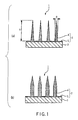
FIG. 1 (a) , amicroneedle array 1 of this embodiment comprises amicroneedle 2 and asubstrate 3 which is provided beneath themicroneedle 2 and supports themicroneedle 2. Themicroneedle 2 is made of PLA, a biocompatible material, and comprises a large number of conical-shaped needle portions 4 integrally formed on asheet portion 5. Thesubstrate 3 is made of acryl (PMMA). Thesheet portion 5 of themicroneedle 2 is thermally fused to the surface of thesubstrate 3, thereby forming themicroneedle array 1. Themicroneedle array 1 has microneedles formed at intervals of 200 to 1,200 microneedles/cm2. - The
needle portions 4 and thesheet portion 5 are made of medical-grade polylactic acid (PLA), a biocompatible material. Theneedle portions 4 have a bottom diameter ϕ of 50 µm to 200 µm and a height h of 100 µm to 500 µm. In consideration of the balance between the degree of penetration of a drug applied to the surface and the degree of invasion due to the stimulation of the sense of pain, it is more preferable that the bottom diameter ϕ be within the range of 80 µm to 120 µm, and the height h be within the range of 200 µm to 400 µm. Further, as inFIG. 1 (b) , in addition to the conical shape, the shape of theneedle portions 4 may be so-called pencil-like, having a cylindrical column shape with a conical upper portion, or may also be a polyangular pyramid whose section is triangle, quadrangle, or the like. - A method for producing the
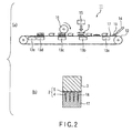
microneedle array 1 is explained with reference toFIG. 2. FIG. 2 (a) is a schematic diagram of aproduction apparatus 11 for themicroneedle array 1 of this embodiment. Theproduction apparatus 11 comprises aconveyor belt 12,heaters 13a to 13e provided along the transferring surface of theconveyor belt 12, anozzle 14 provided in a predetermined position on the upstream portion of the conveyor belt, asubstrate feeder 15 provided in a position downstream thenozzle 14, and aroll 16 provided downstream thesubstrate feeder 15 so as to pressurize the transferring surface of theconveyor belt 12. - First, on the
conveyor belt 12, amold 17 for forming themicroneedle 2 is installed. As shown inFIG. 2 (b) , themold 17 is obtained by forming needle-formingportions 18 in a metal material by a known method such as photolithography, dry etching, or the like. - Next, a solution or a cutting block of medical-
grade PLA 19, a product of Birmingham Polymers Inc., is fed onto themold 17 from thenozzle 14. At this time, the temperature of theheater 13a is set at the melting point (hereinafter referred to as "Tm") ofPLA 19 or higher. - As moving on the
conveyor belt 12, themold 17 is heated with the heater through the belt, whereby thePLA 19 is heated to the temperature range (°C) expressed by the equation (1) below and is spread out over the entire surface of themold 17 to obtain the shape of the large number ofneedle portions 4 integrated at the sheet portion 5 (microneedle formation process). At this time, the temperature of theheater 13b is set at the Tm of PLA.
- Subsequently, the
mold 17 moves on theconveyor belt 12, and asubstrate 3 is installed on themold 17 from thesubstrate feeder 15. Although thesubstrate 3 is made of PMMA as mentioned above, a copolymer of butyl acrylate and methacrylate or the like is also suitable. Further, other plastic materials are also usable. In addition, alumina and metal, which are porous materials, may also be used. At this time, the temperature of theheater 13c is set at a temperature higher than the Tm of PLA by about 20°C, and is adjusted to be in the temperature range of the equation (1) when PLA reaches theheater 13c. - At least the processes from the feeding of PLA onto the mold to the formation of microneedle are to be performed under reduced pressure or vacuum.
- The integrated
substrate 3 andmold 17 are pressurized by theroll 16 and thus closely adhered, and, as shown inFIG. 2 (b) , thesubstrate 3 and thesheet portion 5 are thermally fused (fusion process). At this time, the temperature of theroll 16 is set within the range of the above equation (1) (Tm is the melting point of PLA). - Subsequently, while moving on the
conveyor belt 12, the temperature of thesubstrate 3 and themold 17 are gradually lowered to about 70°C by theheaters substrate 3 integrated with themicroneedle 2 is removed from themold 17, and is punched into a desired shape, thereby giving themicroneedle array 1 of this embodiment. To the surface of theneedle portions 4 of the obtainedmicroneedle array 1, insulin, estradiol, or a like hormone drug, nitroglycerin, or a like desired drug is applied in the form of a spray or a gel to form a drug layer. Thus, themicroneedle array 1 can be used in transcutaneous administration of the drug. - According to the
microneedle array 1 of the invention, theneedle portions 4 are sufficiently adhered to thesubstrate 3 made of PMMA at thesheet portion 5, and thus have sufficient strength to resist plastic deformation even under a load of 5 kgf/cm2 or less. Accordingly, when puncturing through the skin or a like biological surface, the needle portions satisfactorily reach the body tissue without plastic deformation. Further, the needle portions do not break in the body tissue. Even if they break, PLA that forms theneedle portions 4 is decomposed in the body and disappears, and this thus causes no harm to the patient. - Further, because only the
microneedle 2 is made of medical-grade PLA, as compared with the case where the entire microneedle array (i.e., themicroneedle 2 and the substrate 3) is made of medical-grade PLA, the amount of the expensive medical-grade PLA to be used can be reduced by about 50% to about 80%. Accordingly, in comparison with conventional microneedle arrays, the manufacturing cost can be greatly reduced, while maintaining comparable performance. - Further, because the
substrate 3 is made of flexible PMMA, it sufficiently follows the change in skin shape, and there is no need to worry about the separation of themicroneedle 2 from thesubstrate 3, etc. - The
microneedle 2 of this embodiment may haveslots 21 formed on the surface thereof, as shown inFIG. 3 (a) . According to such a structure, when a drug is applied to the surface of themicroneedle 2, the drug is stored in theslots 21. This allows extension of the drug-releasing time and also enables more accurate control of drug release. - Further, as shown in
FIG. 3 (a) , communicating holes (let-out means) 21a each extending from aslot 21 and penetrating through thesheet portion 5 may also be provided. In this case, if adrug layer 22 comprising a polymer impregnated with a drug, for example, is provided in the gap between thesheet portion 5 and thesubstrate 3, the drug is let out from thedrug layer 22 into themicroneedle 2 through the communicatingholes 21a and the release is thus continued even after the whole drug on themicroneedle 2 is released. Accordingly, this allows further extension of the drug-releasing time. Thedrug layer 22 may be provided inside thesubstrate 3, as shown inFIG. 3 (b) . In such a case, the microneedle array is structured so that communicatingholes 21a extend inside thesubstrate 3 and communicate with thedrug layer 22. However, in the case where thesubstrate 3 is formed using the above-mentioned porous material, the drug can be let out to the microneedle without communicating holes being formed.FIGS. 3 (a) and (b) each shows a section of a part of thesubstrate 3, thesheet portion 5, thedrug layer 22, and themicroneedles 2. - Although in the method for producing a microneedle array of this embodiment, a method in which production is performed while the mold and the substrate are moved has been explained, a microneedle array may be produced by heating a fixed mold, feeding PLA or a like biocompatible material thereto from micro-nozzles provided above the mold in correspondence with needle-forming portions to form a microneedle, and thermally fusing it with a substrate.
- Next, a second embodiment of the invention is explained with reference to
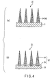
FIG. 4 andFIG. 5 . Themicroneedle array 31 of this embodiment is different from the above first embodiment in that, as shown inFIG. 4 (a) , thesheet portion 5 present in themicroneedle 2 of the first embodiment is not present in amicroneedle 32. The components common with the first embodiment are indicated with the same reference numerals, and duplicate explanations are omitted. - A method for producing the
microneedle array 31 of this embodiment is explained with reference toFIG. 5. FIG. 5 (a) is a schematic diagram of aproduction apparatus 41 for themicroneedle array 31 of this embodiment. Theproduction apparatus 41 comprises aconveyor belt 42; afirst roll 43 provided above theconveyor belt 42; asecond roll 44 provided beneath theconveyor belt 42 to sandwich the conveyor belt together with thefirst roll 43, so that the conveyor belt can be pressurized; anozzle 45 provided in a predetermined position above the first roll; and aknife edge 46 provided in a predetermined position beneath thenozzle 45, in such a manner that the tip thereof contacts the surface of the first roll. Thefirst roll 43 is an imbricate roll, as shown inFIG. 5 (b) , which has the above microneedle-formingmold 17 attached thereto in a many-sided manner with the needle-formingportions 18 facing the outer periphery. - First, a
substrate 3 made of PC is installed on theconveyor belt 42. Next, medical-grade PLA 19, which has been heated to the melting temperature or higher, is fed to the surface of thefirst roll 43 from thenozzle 45. At this time, thefirst roll 43 has also been heated with a non-illustrated heater or the like to thePLA 19 melting temperature or higher. As thefirst roll 43 rotates, meltedPLA 19 approaches theconveyor belt 42. During this process, theknife edge 46 removesexcessive PLA 19 from the surface of thefirst roll 43. For this reason, thesheet portion 5 that is present in themicroneedle 2 in the first embodiment is not formed in this embodiment. - When the
substrate 3 moves on theconveyor belt 42, and is inserted between thefirst roll 43 and thesecond roll 44,PLA 19 melted on the surface of thefirst roll 43 is transferred to the surface of thesubstrate 3 to formmicroneedles 34, and, at the same time, thesubstrate 3 and themicroneedles 34 are thermally fused. At this time, thesecond roll 44 is heated by a non-illustrated heater or the like to a temperature lower than thePLA 19 melting temperature by about 20°C. - After passing between the
first roll 43 and the second rolls 44, thesubstrate 3 is naturally cooled by ambient air while moving on theconveyor belt 42. The thus-obtainedsubstrate 3 having themicroneedles 34 is punched into a desired shape and size, thereby giving themicroneedle array 31 of this embodiment. - According to the
microneedle array 31 of this embodiment, because thesheet portion 5 that is present in the first embodiment is not present in the microneedle 32, the amount of the medical-grade PLA to be used can be further reduced, thereby enabling reduction of manufacturing cost. - Although the
microneedles 34 of this embodiment have a flat bottom, themicroneedles 34 may each have ananchor portion 35 that digs into the substrate as shown inFIG. 4 (b) . In such a case, performing production by the above method using asubstrate 33 having fine asperities previously formed on the surface thereof can form a microneedle array provided withmicroneedles 34 havinganchor portions 35. - Further, in the method for producing a microneedle array of this embodiment, although explained is the case where the
substrate 3 is in the form of a sheet, the substrate may also be a continuous film. Further, by adjusting the distance between theknife edge 46 and thefirst roll 43, it is also possible to form a microneedle provided with a sheet portion, as in the first embodiment. - Next, a third embodiment of the invention is explained with reference to
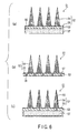
FIG. 6 andFIG. 7 . Amicroneedle array 51 of this embodiment is different from the above embodiments, as shown inFIG. 6 (a) , in that a large number of communicatingholes 56 communicating with asubstrate 53 are formed in asheet portion 55, and that adrug layer 57 is provided beneath the substrate. The components common with the above embodiments are indicated with the same reference numerals, and duplicate explanations are omitted. - A method for producing the
microneedle array 51 of this embodiment is explained with reference toFIG. 7 . Aproduction apparatus 61 for themicroneedle array 51 comprises anouter frame 62, amold 63 to be inserted into theouter frame 62, and apress plate 64. Unlike the above embodiments, theouter frame 62 and themold 63 are previously formed into the shape and size of themicroneedle array 51 to be produced. - The
mold 63 is formed by machining a mold produced by almost the same method as that of the first embodiment into a desired shape and size, however, unlike theabove mold 17, themold 63 has a large number of protrudingportions 65 formed thereon for forming the communicatingholes 56 in thesheet portion 55. - First, as shown in
FIG. 7 (a) , themold 63 is inserted into theouter frame 62, and a block of medical-grade PLA 19 is fed onto themold 63. The block may have any shape, such as the shape of a sphere, a rectangular solid, a cylinder column, or the like. Themold 63 is heated with a non-illustrated heater, etc.PLA 19 is heated by themold 63 to a temperature T°C expressed by the following equation (2), and is spread out in needle-formingportions 66 following the shape of themold 63. The amount ofPLA 19 is an amount to allow thePLA 19 to fill needle-formingportions 66 of themold 63 and further form thesheet portion 55. Subsequently, as shown inFIG. 7 (b) , a pressure of 50 MPa or more is applied by thepress plate 64, then the temperature is lowered, and thepress plate 64 is raised (microneedle formation process). At this time, the protrudingportions 65 fit into the large number of holes provided in the press surface of thepress plate 64. The resultingmicroneedle 52 has, in thesheet portion 55, a large number of communicatingholes 56 formed by the protrudingportions 65.
- Subsequently, as shown in
FIG. 7 (c) , a block ofPMMA 67 used as a material of thesubstrate 53 is fed onto thesheet portion 55. In place ofPMMA 67, polyethylene (PE) or a like material may also be used. A material having a Tm comparable to or lower than that of the material of themicroneedles 54 is preferably used. The amount ofPMMA 67 is adjusted so that when thePMMA 67 is spread out uniformly over thesheet portion 55, the tips of the protrudingportions 65 are not buried. Subsequently, while heatingPMMA 67 to the temperature T calculated by the above equation (2), thepress plate 64 applies a pressure of 50 MPa to compressPMMA 67 as shown inFIG. 7 (d) , and thesubstrate 53 is thus formed (substrate formation and adhesion process). - After the
press plate 64 is raised, themold 63 is removed from theouter frame 62. Then, as shown inFIG. 7 (e) , thedrug layer 57 comprising a polymer impregnated with a desired drug is closely adhered onto thesubstrate 53. After the close adhesion, as shown inFIG. 7 (f) , thesubstrate 53 is removed from themold 63. This provides themicroneedle array 51 of this embodiment, which has a large number of communicatingholes 56 running through thesheet portion 55 and thesubstrate 53 and communicating with thedrug layer 57.FIG. 7 (g) shows an end product formed of themicroneedle array 51 incorporated with apatch member 58 coated with an adhesive material. - According to the
microneedle array 51 of this embodiment, because of the communicatingholes 56 formed in thesheet portion 55, the drug is released through the communicatingholes 56 without being influenced by the behavior of themicroneedles 54 in the body tissue, and thus, stably released into the body tissue through the holes formed in the biological surface by the puncture of themicroneedles 54. Accordingly, drug release can be controlled more stably. - When the amount of charged drug is not large, it is also possible to form the
drug layer 57 only in the communicatingholes 56, as shown inFIG. 6 (b) . Further, in the case where the protrudingportions 65 of themold 63 are provided in the needle-formingportions 66, themicroneedles 54 can be formed into a hollow structure, as shown inFIG. 6 (c) . In such a case, the drug can be administered into the body tissue more efficiently through the communicatingholes 56 formed in themicroneedles 54. - Although examples of a two-layer structure of a microneedle and a substrate have been explained above, the invention may be structured so that, as shown in
FIG. 8 , amicroneedle 101 and asubstrate 102 are formed in a single layer. Such an embodiment is explained hereinafter as a fourth embodiment of the invention. - A method for producing a microneedle array of this embodiment is explained with reference to
FIG. 9 . First, as shown inFIG. 9 (b) , medical-grade PLA 19 is fed onto amold 73 under reduced pressure or vacuum.PLA 19 is heated, and, as shown inFIG. 9 (c) , is spread out in needle-formingportions 66 following the shape of themold 73. The amount ofPLA 19 is an amount to allow thePLA 19 to fill the needle-formingportions 66 of themold 73 and further form asheet portion 65 with a thickness sufficient for thesheet portion 65 to serve as a substrate. Subsequently, as shown inFIG. 9 (d) , a downward pressure is applied by apress plate 74, then the temperature is lowered to cause cooling and solidification, and thepress plate 74 is raised, thereby giving amicroneedle array 64. - According to the
microneedle array 64 of this embodiment, because themicroneedle array 64 is formed of a single layer, the number of manufacturing processes can be reduced, and the productivity can be improved. - As shown in the third embodiment, it is also possible to provide the mold with protruding portions to form communicating holes in the microneedle.
- Embodiments of the invention have been explained thus far. However, the technical scope of the invention is not limited to the above embodiments, and various modifications may be made without deviating from the spirit of the invention.
- For example, although the microneedle is made of medical-grade PLA in the above embodiments, insofar as the medical grade is satisfied, PLGA, chitin, chitosan, hyaluronic acid, collagen, glucose, cellulose, magnesium alloy, and other biocompatible materials may also be used. Further, the microneedle may also be made of a mixed material of the above biocompatible materials and the drug. In such a case, the drug is released by dissolution of the microneedle in the body tissue.
- Further, although the substrate is made of PMMA in the above embodiments, as mentioned above, a copolymer of butyl acrylate and butyl methacrylate, polycarbonate, polyurethane, polypropylene, and other resin materials, metals, ceramics, and the like may also be used. In addition, PLA and like materials of a grade lower than the medical grade are also usable. In view of the conformability with the change in shape of the biological surface, the substrate is preferably made of a highly expansible resin material. Further, it is also possible that a plurality of layers made of the above various materials be integrated to form a substrate.
- Further, although the substrate and the microneedle are adhered by thermal fusion in the above embodiments, they may be adhered by plasma welding. Further, although the substrate and the microneedle are formed by compression molding in the above embodiment, a common plastic molding technique, such as injection molding or the like, may be used instead to form the substrate and the microneedle.
- While vacuuming, PLA on a mold was heated to 210°C. The PLA was charged into needle-forming portions, and then cooled and solidified at normal temperature over 1 hour, thereby molding a microneedle array. For the molding of microneedles, the apparatus shown in
FIG. 9 was used. - The molded microneedle array was removed, and the shape of the needle tip portions was observed. As a result, the needle tip portions were sharp, and the tip portions of all the microneedles on the microneedle array had the same shape.
- PLA on a mold was heated to 210°C without vacuuming. The PLA was charged into needle-forming portions, and then cooled and solidified at normal temperature over 1 hour, thereby molding a microneedle array. For the molding of microneedles, the apparatus shown in
FIG. 9 was used. - The molded microneedle array was removed, and the shape of the needle tip portions was observed. As a result, rounded tip portions were observed in 80 needles out of every 800. The microneedles varied in shape and height.
- Chitin was dissolved in chloroform to give a resin fluid. The resin fluid was fed onto the mold, and vacuuming was performed while increasing the temperature to 60°C. After 1 hour, at the time when the organic solvent chloroform evaporated, the temperature was lowered to normal temperature, whereby only a chitin molded product was left on the mold. A chitin microneedle array was thus obtained. For the molding of microneedles, the apparatus shown in
FIG. 9 was used. - The molded microneedle array was removed, and the shape of the needle tip portions was observed. As a result, the needle tip portions were sharp, and all the microneedle tip portions on the microneedle array had the same shape.
- Chitin was dissolved in chloroform to give a resin fluid. The resin fluid was fed onto the mold, and charged into the mold while increasing the mold temperature to 60°C.
- After 1 hour, the temperature was lowered to normal temperature, thereby molding a microneedle array. For the molding of the microneedle array, the apparatus shown in
FIG. 9 was used. - The obtained microneedle array contained the organic solvent chloroform remaining therein, and thus was unusable for puncturing through a biological surface.
- Chitosan, a protein preparation, and water were mixed to give a resin fluid. The resin fluid was fed onto the mold, and the mold was heated to 40°C. Vacuuming was performed, and the mold was maintained at 40°C and left to stand for 1 hour in this state. Subsequently, the temperature was lowered to normal temperature, whereby only a chitosan molded product was left on the mold. A chitosan microneedle array was thus obtained. For the molding of the microneedle array, the apparatus shown in
FIG. 9 was used. - The molded microneedle array was removed, and the shape of the needle tip portions was observed. As a result, the needle tip portions were sharp, and all the microneedle tip portions on the microneedle array had the same shape.
- Chitosan, a protein preparation, and water were mixed to give a resin fluid. The resin fluid was fed onto the mold. The mold was heated to 40°C and left to stand for 10 hours in this state. After 10 hours, the mold temperature was lowered to normal temperature, and molding was thus performed. For the molding of microneedles, the apparatus shown in
FIG. 9 was used. - In Comparative Example 3, solidification into the microneedle array shape took time ten times longer than time required when vacuuming was included.
- The invention can be used as a microneedle array for medical applications.
-
-
FIG. 1 is sectional views each schematically showing a microneedle array according to a first embodiment of the invention; -
FIG. 2 shows a production method according to the same embodiment; -
FIG. 3 is partial sectional views each schematically showing a modified example according to the same embodiment; -
FIG. 4 is sectional views each schematically showing a microneedle array according to a second embodiment of the invention; -
FIG. 5 shows a production method according to the same embodiment; -
FIG. 6 is sectional views each schematically showing a microneedle array according to a third embodiment of the invention; -
FIG. 7 shows a production method according to the same embodiment; -
FIG. 8 is a sectional view schematically showing a microneedle array according to a fourth embodiment of the invention; and -
FIG. 9 shows a production method according to the same embodiment. -
- 1, 31, 51,
- 64: Microneedle array
- 2, 32, 52:
- Microneedle
- 3, 33, 53:
- Substrate
- 4, 34, 54:
- Microneedle
- 17, 63, 73:
- Mold
- 19:
- Polylactic acid (biocompatible material)
- 21a:
- Communicating hole (let-out means)
- 22,
- 57: Drug layer
Claims (14)
- A method for producing a microneedle, characterized by comprising:a feeding step of feeding a resin fluid to a forming mold having a needle-forming portion with an opening diameter of 50 to 200 µm and a depth of 100 to 500 µm;a charging step of charging the fed resin fluid into the needle-forming portion; anda solidifying step of cooling and solidifying the charged resin fluid,wherein the feeding step, the charging step, and the solidifying step are performed under reduced pressure or vacuum.
- A method for producing a microneedle, characterized by comprising:a feeding step of feeding a resin fluid to a forming mold having a needle-forming portion with an opening diameter of 50 to 200 µm and a depth of 100 to 500 µm;an overheating and melting step of fluidizing the fed resin to produce a resin fluid;a charging step of charging the resin fluid into the needle-forming portion; anda solidifying step of cooling and solidifying the charged resin fluid,wherein the feeding step, the overheating and melting step, the charging step, and the solidifying step are performed under reduced pressure or vacuum.
- The method for producing a microneedle according to claim 1 or 2, characterized in that the forming mold has two or more needle-forming portions.
- The method for producing a microneedle according to one of claims 1 to 3, characterized in that the forming mold has a protruding portion in an area other than the needle-forming portion.
- The method for producing a microneedle according to one of claims 1 to 3, characterized in that the forming mold has a protruding portion in the needle-forming portion.
- The method for producing a microneedle according to one of claims 1 to 5, characterized in that the step of charging the resin fluid is performed by pressing the resin fluid.
- The method for producing a microneedle according to one of claims 1 to 6, characterized in that in the step of charging the resin fluid, the resin fluid is placed also in an area on the forming mold other than the needle-forming portion.
- The method for producing a microneedle according to one of claims 1 to 7, characterized in that the resin contains a biocompatible material.
- The method for producing a microneedle according to claim 8, characterized in that the biocompatible material is a material containing one of polylactic acid, glycol lactic acid, chitin, chitosan, hyaluronic acid, collagen, glucose/cellulose, and magnesium alloy.
- A microneedle characterized in that it is produced by the producing method according to one of claims 1 to 9.
- The microneedle according to claim 10, characterized in that the microneedle does not undergo plastic deformation under a load of 5 kg/cm2 or less.
- A method for producing a microneedle array, characterized by comprising:a placing step of placing, after forming the microneedle by the producing method according to one of claims 1 to 9, a substrate such that it faces the needle-forming portion of the forming mold with the microneedle interposed therebetween; anda stacking step of integrating the needle-forming portion and the substrate together.
- The method for producing a microneedle array according to claim 12, characterized in that the microneedle and the substrate are made of different materials.
- A microneedle array characterized in that it is manufactured by claim 12 or claim 13.
Applications Claiming Priority (2)
| Application Number | Priority Date | Filing Date | Title |
|---|---|---|---|
| JP2006315371 | 2006-11-22 | ||
| PCT/JP2007/072555 WO2008062832A1 (en) | 2006-11-22 | 2007-11-21 | Microneedle array and process for production thereof |
Publications (2)
| Publication Number | Publication Date |
|---|---|
| EP2090331A1 true EP2090331A1 (en) | 2009-08-19 |
| EP2090331A4 EP2090331A4 (en) | 2012-04-18 |
Family
ID=39429761
Family Applications (1)
| Application Number | Title | Priority Date | Filing Date |
|---|---|---|---|
| EP07832285A Withdrawn EP2090331A4 (en) | 2006-11-22 | 2007-11-21 | Microneedle array and process for production thereof |
Country Status (4)
| Country | Link |
|---|---|
| US (1) | US20090234301A1 (en) |
| EP (1) | EP2090331A4 (en) |
| JP (1) | JPWO2008062832A1 (en) |
| WO (1) | WO2008062832A1 (en) |
Cited By (6)
| Publication number | Priority date | Publication date | Assignee | Title |
|---|---|---|---|---|
| CN104780968A (en) * | 2012-11-13 | 2015-07-15 | 富士胶片株式会社 | Transdermal absorption sheet, and manufacturing method for same |
| CN104888343A (en) * | 2015-05-07 | 2015-09-09 | 北京化工大学 | Macromolecule solid micro needle and batched preparing method thereof |
| WO2018124808A1 (en) * | 2016-12-29 | 2018-07-05 | 랩앤피플주식회사 | Micro needle |
| KR20180077879A (en) * | 2016-12-29 | 2018-07-09 | 랩앤피플주식회사 | Multi type micro-needle |
| EP3444003A4 (en) * | 2016-04-07 | 2019-11-13 | Labnpeople Co.,Ltd. | Microneedle using biodegradable metal |
| WO2021032701A1 (en) * | 2019-08-22 | 2021-02-25 | Lts Lohmann Therapie-Systeme Ag | Device and method for producing microstructures |
Families Citing this family (62)
| Publication number | Priority date | Publication date | Assignee | Title |
|---|---|---|---|---|
| JP2009083125A (en) * | 2007-09-27 | 2009-04-23 | Fujifilm Corp | Method and apparatus for producing functional film |
| JP5120624B2 (en) * | 2008-01-31 | 2013-01-16 | 芳一 飛永 | Fine sugar needle, manufacturing method and manufacturing apparatus |
| JP5183375B2 (en) * | 2008-09-04 | 2013-04-17 | 凸版印刷株式会社 | Needle-shaped body manufacturing method, needle-shaped body manufacturing apparatus, and needle-shaped body |
| JP5233534B2 (en) * | 2008-09-11 | 2013-07-10 | 凸版印刷株式会社 | Acicular body |
| JP5472673B2 (en) * | 2008-09-29 | 2014-04-16 | コスメディ製薬株式会社 | Microneedle array |
| KR20100037389A (en) * | 2008-10-01 | 2010-04-09 | 연세대학교 산학협력단 | Solid microstructure with multi-controlled release and process for preparing the same |
| EP2379307B1 (en) * | 2008-12-29 | 2013-03-13 | 3M Innovative Properties Company | Polylactide films having structured surface and methods for making the same |
| JP5402069B2 (en) * | 2009-02-20 | 2014-01-29 | 凸版印刷株式会社 | Manufacturing method of needle-like structure |
| JP5343653B2 (en) * | 2009-03-25 | 2013-11-13 | 凸版印刷株式会社 | Molding apparatus and molding method for molded product |
| JP5072899B2 (en) * | 2009-04-17 | 2012-11-14 | 株式会社日本製鋼所 | Manufacturing method and manufacturing apparatus for microstructured body having through hole |
| JP2011012050A (en) * | 2009-06-03 | 2011-01-20 | Bioserentack Co Ltd | Microneedle array using porous substrate and method for producing the same |
| RU2585138C2 (en) | 2010-04-28 | 2016-05-27 | Кимберли-Кларк Ворлдвайд, Инк. | Medical devices for delivery of sirna |
| JP5152935B2 (en) * | 2010-04-28 | 2013-02-27 | 株式会社日本製鋼所 | Manufacturing method of microstructured molded body having through-hole and microstructured molded body material |
| JP5871907B2 (en) * | 2010-04-28 | 2016-03-01 | キンバリー クラーク ワールドワイド インコーポレイテッド | Nanopatterned medical device with enhanced cell-cell interaction |
| WO2011140274A2 (en) | 2010-05-04 | 2011-11-10 | Corium International, Inc. | Method and device for transdermal delivery of parathyroid hormone using a microprojection array |
| GB2483505B (en) * | 2010-09-13 | 2012-10-10 | Ndm Technologies Ltd | Devices for transdermal drug delivery |
| JP2012235899A (en) * | 2011-05-12 | 2012-12-06 | Bioserentack Co Ltd | Microneedle array chip for delivering large amount of target substance into skin |
| WO2012167162A2 (en) * | 2011-06-03 | 2012-12-06 | University Of Washington | Methods for the production of chitin nanofibers and uses thereof |
| JP2013162861A (en) * | 2012-02-10 | 2013-08-22 | Bioserentack Co Ltd | Microneedle for monitoring intercellular fluid |
| EP2815784A4 (en) * | 2012-02-17 | 2015-07-01 | Cosmed Pharmaceutical Co Ltd | Microneedle of short-time dissolution type |
| KR102088651B1 (en) * | 2012-02-29 | 2020-03-16 | 도판 인사츠 가부시키가이샤 | Needle-like material and method for manufacturing needle-like material |
| JP2013216044A (en) * | 2012-04-11 | 2013-10-24 | Teijin Ltd | Method of molding laminate molded article |
| CN104780967B (en) * | 2012-11-13 | 2017-04-12 | 富士胶片株式会社 | Method for manufacturing transdermal-absorption sheet |
| JP2014097163A (en) * | 2012-11-14 | 2014-05-29 | Ikeda Kikai Sangyo Kk | Method of manufacturing microneedle array |
| JP6111634B2 (en) * | 2012-12-10 | 2017-04-12 | 凸版印刷株式会社 | Needle-like structure manufacturing equipment |
| ES2743404T3 (en) | 2012-12-21 | 2020-02-19 | Corium Inc | Matrix for therapeutic agent supply and manufacturing method |
| US20150352777A1 (en) * | 2013-01-18 | 2015-12-10 | The University Of North Carolina At Chapel Hill | High-throughput manufacturing of microneedles |
| EP2968887B1 (en) | 2013-03-12 | 2022-05-04 | Corium, Inc. | Microprojection applicators |
| WO2014152717A2 (en) * | 2013-03-14 | 2014-09-25 | Sano Intelligence, Inc. | On-body microsensor for biomonitoring |
| US10820860B2 (en) | 2013-03-14 | 2020-11-03 | One Drop Biosensor Technologies, Llc | On-body microsensor for biomonitoring |
| EP2968118B1 (en) | 2013-03-15 | 2022-02-09 | Corium, Inc. | Microarray for delivery of therapeutic agent and methods of use |
| JPWO2014175310A1 (en) | 2013-04-26 | 2017-02-23 | 凸版印刷株式会社 | Manufacturing method of needle-shaped body |
| WO2014196522A1 (en) * | 2013-06-03 | 2014-12-11 | 凸版印刷株式会社 | Needle body manufacturing method and manufacturing device |
| EP3028735A4 (en) * | 2013-07-30 | 2017-04-12 | Asti Corporation | Microneedle array and microneedle array manufacturing method |
| JP5652524B2 (en) * | 2013-09-10 | 2015-01-14 | 凸版印刷株式会社 | Needle-like structure manufacturing equipment |
| JP5652525B2 (en) * | 2013-09-10 | 2015-01-14 | 凸版印刷株式会社 | Needle-like structure manufacturing equipment |
| JP5931110B2 (en) * | 2014-03-26 | 2016-06-08 | 日本写真印刷株式会社 | Method for manufacturing conical projection sheet packaging |
| JP5892303B1 (en) * | 2014-06-13 | 2016-03-23 | 凸版印刷株式会社 | Manufacturing method of needle-shaped body |
| EP3188714A1 (en) | 2014-09-04 | 2017-07-12 | Corium International, Inc. | Microstructure array, methods of making, and methods of use |
| US10973757B2 (en) * | 2014-10-06 | 2021-04-13 | StemProtein, LLC | Biodegardable microneedle device |
| US20210346664A1 (en) * | 2014-10-06 | 2021-11-11 | Nikolai Tankovich | Sandwiched biodegradable microneedle |
| KR101676861B1 (en) * | 2015-04-10 | 2016-11-17 | 씨앤텍 주식회사 | Manufacturing machines and method for micro-needle patch and micro-needle patch manufactured by the same |
| US10857093B2 (en) * | 2015-06-29 | 2020-12-08 | Corium, Inc. | Microarray for delivery of therapeutic agent, methods of use, and methods of making |
| US20180296982A1 (en) * | 2015-10-20 | 2018-10-18 | National Research Council Of Canada | Polymer membranes having open through holes, and method of fabrication thereof |
| JP6558812B2 (en) * | 2015-12-18 | 2019-08-14 | 株式会社ラボ・ジュヴェルサ | Microneedle and microneedle patch |
| CN105498082B (en) * | 2015-12-24 | 2017-10-27 | 广州新济药业科技有限公司 | Micropin chip and preparation method thereof |
| KR101636070B1 (en) * | 2015-12-30 | 2016-07-14 | 주식회사 라파스 | Manufacturing device for micro-needle |
| JP2017131397A (en) * | 2016-01-27 | 2017-08-03 | 花王株式会社 | Method of producing fine, and hollow projection tool |
| AU2017232609B2 (en) * | 2016-03-16 | 2022-01-13 | Cosmed Pharmaceutical Co., Ltd. | Microneedle patch case |
| WO2017204418A1 (en) * | 2016-05-23 | 2017-11-30 | 주식회사유한양행 | Microneedle patch containing bleomycin for verruca treatment and method for manufacturing same |
| KR101697556B1 (en) * | 2016-08-05 | 2017-01-18 | 이상혁 | Apparatus and method for manufacturing microstructures and microstructures prepared by the same |
| KR101716447B1 (en) * | 2016-09-30 | 2017-03-14 | 이상혁 | Method for manufacturing microneedles using vibration and gravity |
| KR101868872B1 (en) * | 2016-10-28 | 2018-06-19 | 권영덕 | Micro-needle and manufacturing method thereof |
| KR101905040B1 (en) | 2017-04-19 | 2018-10-08 | (주) 오스타테크 | The Filling Device of Micro Needle and It's Filling Method |
| JP6965068B2 (en) * | 2017-09-13 | 2021-11-10 | 花王株式会社 | Hollow protrusion manufacturing method, hollow protrusion manufacturing equipment, and hollow protrusion |
| KR102296331B1 (en) * | 2017-11-15 | 2021-08-30 | 주식회사 엘지생활건강 | Apparatus and Process for Continuous Production of Microneedle |
| KR102184940B1 (en) * | 2017-11-15 | 2020-12-01 | 주식회사 엘지생활건강 | Apparatus and Process for Continuous Production of Microneedle |
| KR102139335B1 (en) | 2017-11-24 | 2020-07-29 | 주식회사 엘지생활건강 | Method and Apparatus for Manufacturing Microneedle Containing Coatings on Needle Tip |
| EP3520979B1 (en) * | 2018-02-01 | 2022-12-28 | SABIC Global Technologies B.V. | Microneedle array and method of manufacturing a microneedle array |
| CN111770824B (en) * | 2018-03-27 | 2021-11-23 | 富士胶片株式会社 | Method for manufacturing mold with concave base pattern and method for manufacturing pattern sheet |
| JP6956680B2 (en) * | 2018-05-16 | 2021-11-02 | 富士フイルム株式会社 | Manufacturing method of mold case and microneedle array |
| CN111298279B (en) * | 2018-12-11 | 2024-01-26 | 尹忠 | Preparation device and preparation method of drug administration microneedle |
Citations (2)
| Publication number | Priority date | Publication date | Assignee | Title |
|---|---|---|---|---|
| US20020020688A1 (en) * | 1999-06-09 | 2002-02-21 | The Procter & Gamble Company | Apparatus and method for manufacturing an intracutaneous microneedle array |
| US20050178760A1 (en) * | 2004-02-17 | 2005-08-18 | Eng-Pi Chang | Method of making microneedles |
Family Cites Families (15)
| Publication number | Priority date | Publication date | Assignee | Title |
|---|---|---|---|---|
| US4163900A (en) * | 1977-08-17 | 1979-08-07 | Connecticut Research Institute, Inc. | Composite electron microscope grid suitable for energy dispersive X-ray analysis, process for producing the same and other micro-components |
| JPH10146206A (en) * | 1996-09-19 | 1998-06-02 | Ykk Corp | Integrally molded hook-and-loop fastener member and its production |
| US6256533B1 (en) * | 1999-06-09 | 2001-07-03 | The Procter & Gamble Company | Apparatus and method for using an intracutaneous microneedle array |
| EP1235611B1 (en) * | 1999-11-15 | 2005-09-07 | Velcro Industries B.V. | Skin attachment member |
| NL1016779C2 (en) * | 2000-12-02 | 2002-06-04 | Cornelis Johannes Maria V Rijn | Mold, method for manufacturing precision products with the aid of a mold, as well as precision products, in particular microsieves and membrane filters, manufactured with such a mold. |
| EP1345646A2 (en) * | 2000-12-14 | 2003-09-24 | Georgia Tech Research Corporation | Microneedle devices and production thereof |
| US6767341B2 (en) | 2001-06-13 | 2004-07-27 | Abbott Laboratories | Microneedles for minimally invasive drug delivery |
| US6908453B2 (en) * | 2002-01-15 | 2005-06-21 | 3M Innovative Properties Company | Microneedle devices and methods of manufacture |
| US6899838B2 (en) * | 2002-07-12 | 2005-05-31 | Becton, Dickinson And Company | Method of forming a mold and molding a micro-device |
| US20050008821A1 (en) * | 2003-07-07 | 2005-01-13 | Pricone Robert M. | Process and apparatus for fabricating precise microstructures and polymeric molds for making same |
| WO2005009645A2 (en) * | 2003-07-21 | 2005-02-03 | 10X Technology Llc. | Apparatus and method for manufacturing microneedles |
| US20070191761A1 (en) * | 2004-02-23 | 2007-08-16 | 3M Innovative Properties Company | Method of molding for microneedle arrays |
| AU2006209421A1 (en) * | 2005-01-31 | 2006-08-03 | Bioserentach Co., Ltd. | Transdermal absorption preparation, sheet holding transdermal absorption preparation and transdermal absorption preparation holder |
| JP5020080B2 (en) * | 2005-05-13 | 2012-09-05 | 久光製薬株式会社 | Manufacturing method of medical equipment |
| TW200829215A (en) * | 2007-01-03 | 2008-07-16 | Univ Nat Chiao Tung | Micro probe array and manufacturing method of the trans-print mold thereof |
-
2007
- 2007-11-21 JP JP2008545431A patent/JPWO2008062832A1/en active Pending
- 2007-11-21 WO PCT/JP2007/072555 patent/WO2008062832A1/en active Application Filing
- 2007-11-21 EP EP07832285A patent/EP2090331A4/en not_active Withdrawn
-
2009
- 2009-05-21 US US12/453,783 patent/US20090234301A1/en not_active Abandoned
Patent Citations (2)
| Publication number | Priority date | Publication date | Assignee | Title |
|---|---|---|---|---|
| US20020020688A1 (en) * | 1999-06-09 | 2002-02-21 | The Procter & Gamble Company | Apparatus and method for manufacturing an intracutaneous microneedle array |
| US20050178760A1 (en) * | 2004-02-17 | 2005-08-18 | Eng-Pi Chang | Method of making microneedles |
Non-Patent Citations (1)
| Title |
|---|
| See also references of WO2008062832A1 * |
Cited By (6)
| Publication number | Priority date | Publication date | Assignee | Title |
|---|---|---|---|---|
| CN104780968A (en) * | 2012-11-13 | 2015-07-15 | 富士胶片株式会社 | Transdermal absorption sheet, and manufacturing method for same |
| CN104888343A (en) * | 2015-05-07 | 2015-09-09 | 北京化工大学 | Macromolecule solid micro needle and batched preparing method thereof |
| EP3444003A4 (en) * | 2016-04-07 | 2019-11-13 | Labnpeople Co.,Ltd. | Microneedle using biodegradable metal |
| WO2018124808A1 (en) * | 2016-12-29 | 2018-07-05 | 랩앤피플주식회사 | Micro needle |
| KR20180077879A (en) * | 2016-12-29 | 2018-07-09 | 랩앤피플주식회사 | Multi type micro-needle |
| WO2021032701A1 (en) * | 2019-08-22 | 2021-02-25 | Lts Lohmann Therapie-Systeme Ag | Device and method for producing microstructures |
Also Published As
| Publication number | Publication date |
|---|---|
| EP2090331A4 (en) | 2012-04-18 |
| JPWO2008062832A1 (en) | 2010-03-04 |
| US20090234301A1 (en) | 2009-09-17 |
| WO2008062832A1 (en) | 2008-05-29 |
Similar Documents
| Publication | Publication Date | Title |
|---|---|---|
| EP2090331A1 (en) | Microneedle array and process for production thereof | |
| EP2343101A1 (en) | Stamper for microneedle sheet, method for manufacturing the stamper, and method for manufacturing microneedle using the stamper | |
| CN104736192B (en) | For by the application device and method of microneedle devices application to skin | |
| EP2934660B1 (en) | Microarray for delivery of therapeutic agent and method of making same | |
| CN104321105B (en) | Micropin and microneedle array | |
| EP2343102A1 (en) | Method for manufacturing microneedle stamper | |
| KR101724655B1 (en) | Micro-needle patch and menufacturing method thereof | |
| CA2546688C (en) | Device for the transdermal administration of active ingredients | |
| EP3409318A1 (en) | Microneedle array, and microneedle sheet | |
| WO2008020632A1 (en) | Microneedle and microneedle patch | |
| CA2528512A1 (en) | Process for producing pad base for transdermal drug administration, pad base for transdermal drug administration and needle | |
| CN105283216A (en) | Microneedle injection apparatus comprising an inverted actuator | |
| WO2008015782A1 (en) | Microneedle patch and process for producing the same | |
| CN106853271B (en) | Method for producing microstructure | |
| JP2005021678A (en) | Pad base for percutaneous admistration and its manufacturing method | |
| CN108939283B (en) | Human body safe degradable microneedle array and manufacturing method and mold thereof | |
| KR102249513B1 (en) | A candle-typed microstructure for transdermal delivery and a method for manufacturing the same | |
| WO2018062690A1 (en) | Method for manufacturing microneedles by using vibration and gravity | |
| EP3363491B1 (en) | Administration instrument | |
| EP3251721A1 (en) | Transdermal administration device | |
| KR101697556B1 (en) | Apparatus and method for manufacturing microstructures and microstructures prepared by the same | |
| JP2003321350A (en) | Percutaneously absorbable preparation and method for percutaneously absorbing drug using the same | |
| Jiawook | Manufacturing nanoimprint lithography system to produce efficient microneedles patch for transdermal drug delivery | |
| JP4237819B1 (en) | Transdermal preparation | |
| CA2696956A1 (en) | Stamper for microneedle sheet, production method thereof, and microneedle production method using stamper |
Legal Events
| Date | Code | Title | Description |
|---|---|---|---|
| PUAI | Public reference made under article 153(3) epc to a published international application that has entered the european phase |
Free format text: ORIGINAL CODE: 0009012 |
|
| 17P | Request for examination filed |
Effective date: 20090520 |
|
| AK | Designated contracting states |
Kind code of ref document: A1 Designated state(s): AT BE BG CH CY CZ DE DK EE ES FI FR GB GR HU IE IS IT LI LT LU LV MC MT NL PL PT RO SE SI SK TR |
|
| DAX | Request for extension of the european patent (deleted) | ||
| A4 | Supplementary search report drawn up and despatched |
Effective date: 20120319 |
|
| RIC1 | Information provided on ipc code assigned before grant |
Ipc: B29C 43/56 20060101ALI20120312BHEP Ipc: B29C 59/02 20060101ALN20120312BHEP Ipc: B29C 43/36 20060101ALN20120312BHEP Ipc: A61M 37/00 20060101AFI20120312BHEP Ipc: B29C 43/02 20060101ALI20120312BHEP |
|
| RIC1 | Information provided on ipc code assigned before grant |
Ipc: A61M 37/00 20060101AFI20161129BHEP Ipc: B29C 43/02 20060101ALI20161129BHEP Ipc: B29C 43/36 20060101ALN20161129BHEP Ipc: B29C 43/56 20060101ALI20161129BHEP Ipc: B29C 59/02 20060101ALN20161129BHEP |
|
| RIC1 | Information provided on ipc code assigned before grant |
Ipc: B29C 43/02 20060101ALI20161220BHEP Ipc: B29C 43/56 20060101ALI20161220BHEP Ipc: A61M 37/00 20060101AFI20161220BHEP Ipc: B29C 59/02 20060101ALN20161220BHEP Ipc: B29C 43/36 20060101ALN20161220BHEP |
|
| STAA | Information on the status of an ep patent application or granted ep patent |
Free format text: STATUS: THE APPLICATION HAS BEEN WITHDRAWN |
|
| 18W | Application withdrawn |
Effective date: 20170314 |