EP2090919B1 - Signal processing system - Google Patents
Signal processing system Download PDFInfo
- Publication number
- EP2090919B1 EP2090919B1 EP09000681.8A EP09000681A EP2090919B1 EP 2090919 B1 EP2090919 B1 EP 2090919B1 EP 09000681 A EP09000681 A EP 09000681A EP 2090919 B1 EP2090919 B1 EP 2090919B1
- Authority
- EP
- European Patent Office
- Prior art keywords
- section
- endoscope
- log data
- setting
- user
- Prior art date
- Legal status (The legal status is an assumption and is not a legal conclusion. Google has not performed a legal analysis and makes no representation as to the accuracy of the status listed.)
- Expired - Fee Related
Links
Images


Classifications
-
- G—PHYSICS
- G02—OPTICS
- G02B—OPTICAL ELEMENTS, SYSTEMS OR APPARATUS
- G02B23/00—Telescopes, e.g. binoculars; Periscopes; Instruments for viewing the inside of hollow bodies; Viewfinders; Optical aiming or sighting devices
- G02B23/24—Instruments or systems for viewing the inside of hollow bodies, e.g. fibrescopes
- G02B23/2476—Non-optical details, e.g. housings, mountings, supports
- G02B23/2484—Arrangements in relation to a camera or imaging device
Definitions
- Endoscopes are widely used in medical and industrial fields. Recent years have seen wide use of endoscope apparatuses that include an endoscope equipped with an external television camera, which is constructed by attaching a television camera having image pickup means to the eye cup of the optical endoscope, or include an electronic endoscope having image pickup means built in the distal end portion of the endoscope, and display an image captured by the endoscope on the monitor to enable the user to perform observation and treatment while viewing the displayed image.
- endoscope apparatuses employ a light source apparatus for supplying illumination light to the endoscope, a camera control unit (also referred to as "video processor") including an image signal processing circuit for displaying an endoscopic image, a TV monitor for displaying the endoscopic image, as well as a plurality of peripheral apparatuses such as, e.g., an insufflation apparatus and high frequency cauterization apparatus.
- a light source apparatus for supplying illumination light to the endoscope
- a camera control unit also referred to as "video processor”
- peripheral apparatuses such as, e.g., an insufflation apparatus and high frequency cauterization apparatus.
- the plurality of peripheral apparatuses are typically connected to a system controller for concentrated control.
- the peripheral apparatuses of the endoscope system are equipped with electronic instruments such as an image pickup device and image processing means, precise mechanisms such as filter drive mechanism for sequentially irradiating light beams of RGB three colors, and consumable items such as a light source lamp, etc. Therefore the peripheral apparatuses normally require periodical maintenance by maintenance workers having related expertise.
- a single maintenance worker is in charge of maintaining a plurality of electronic endoscopes and the endoscope processors.
- the maintenance worker carries out the work of maintaining electronic endoscopes and endoscope processors that are remotely located. This situation has caused problems including high maintenance cost and inability to quickly address abnormalities that the electronic endoscopes and endoscope processor may have.
- Japanese Patent Application Laid-Open Publication No. 2002-263063 discloses an endoscope system that allows the maintenance work to be quickly conducted even at a remote location, employing a technique which allows a remotely located service server to monitor endoscope processors installed in a plurality of facilities and instruments connected to the endoscope processors.
- Japanese Patent Application Laid-Open Publication No. 2005-111080 proposes a surgery support system that during surgery constantly maintains the settings of instruments in the surgery room at appropriate states, thus enabling it to remotely provide an appropriate surgery support.
- the image color tone may be changed by switching of observation modes (normal light, NBI, AFI) or change of color tone by user operation.
- observation modes normal light, NBI, AFI
- an unintended user operation may erroneously change the image color tone, making the user have a sense of incongruity on the resulting image.
- a user having a sense of incongruity on (the color tone of) the observation image, may not be able to identify whether the incongruity is due to an instrument abnormality or simply a setting changing operation not intended by the user.
- This situation deprives the user of an appropriate field service (e.g., a service man may be sent to check the instruments even if the instruments are not abnormal), disabling the user to use the instruments during the instrument checking and waiting time.
- the inspection efficiency is thus problematically decreased.
- the present invention has been made in view of the above circumstances and has its object to provide an endoscope system that allows the user to take appropriate measures by monitoring whether the image deficiency is due to an instrument abnormality or whether the image merely appears deficient due to a setting change operation not intended by the user.
- a signal processing system comprises an endoscope for picking up an image of an inner body cavity by an image-pickup section; a light source for supplying illumination light to the endoscope; and a signal processing device including a plurality of signal processing sections for processing image-pickup signals from the endoscope, wherein the signal processing device includes: a control section for controlling, based on a setting value, operation of at least one of an internal circuit of the endoscope, an internal circuit of the signal processing section, and an internal circuit of the light source; a setting value changing section for changing the setting value; a log recording section for recording change history of the setting value as log data; a data sending section for sending the log data to an external instrument via a network; and a command receiving section for receiving a control command which is based on the log data from the external instrument via the network.
- control section controls the setting value changing section based on the control command receivedid from the external instrument.
- a support facility for remotely supporting an operation of a user system, including the signal processing system according to first and second aspect of the invention as described above.
- the support facility comprises a log data receiving section for receiving, via a network, setting state log data, for example from the log data sending section of the signal processing system according to the first and second aspect described above; a log data analyzing section for analyzing the received setting state log data; and a restore command sending section for sending a restore command which is based on an analysis result of the log data analyzing section, for example to a restoration operation activating section of the signal processing system according to the first or second aspect described above.
- FIGS. 1 to 26 relate to a first embodiment of the present invention.
- FIG. 1 is a configuration diagram showing a configuration of an endoscope system.
- FIG. 2 is a block diagram showing a configuration of a CCU of FIG. 1 .
- FIG. 3 is a view showing a configuration of an operation panel of FIG. 2 .
- FIG. 4 is a view showing a configuration of a keyboard of FIG. 2 .
- FIG. 5 is a view showing a data format configuration of operation log data to be stored in a log memory of FIG. 2 .
- FIG. 6 is a first view showing a specific data configuration of the data format configuration of FIG. 5 .
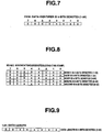
- FIG. 7 is a second view showing a specific data configuration of the data format configuration of FIG. 5 .
- FIG. 1 is a configuration diagram showing a configuration of an endoscope system.
- FIG. 2 is a block diagram showing a configuration of a CCU of FIG. 1 .
- FIG. 3 is a view showing a
- FIG. 8 is a third view showing a specific data configuration of the data format configuration of FIG. 5 .
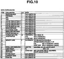
- FIG. 9 is a fourth view showing a specific data configuration of the data format configuration of FIG. 5 .
- FIG. 10 is a fifth view showing a specific data configuration of the data format configuration of FIG. 5 .
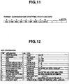
- FIG. 11 is a view showing a data format configuration of setting state log data to be stored in the log memory of FIG. 2 .
- FIG. 12 is a view showing a specific data configuration of the data format configuration of FIG. 11 .
- FIG. 13 is a flow chart showing a flow of a processing for storing of system log data in the CCU of FIG. 2 .
- FIG. 14 is a flow chart showing a flow of a processing for checking the setting state of the system log data.
- FIG. 14 is a flow chart showing a flow of a processing for checking the setting state of the system log data.
- FIG. 15 is a function block diagram showing a function of the endoscope system of FIG. 1 .
- FIG. 16 is a function block diagram showing a function of a log data analyzing section of FIG. 15 .
- FIG. 17 is a view showing a data format configuration of a restore command generated by a log data analyzing section of FIG. 16 .
- FIG. 18 is a view showing a data configuration of a command body CMD of the restore command of FIG. 17 .
- FIG. 19 is a view illustrating the content of the restore command of FIG. 17 .
- FIG. 20 is a view illustrating operation transition of the endoscope system of FIG. 1 .
- FIG. 21 is a view illustrating a manner of indication of a setting switch in the operation transition of FIG. 20 .
- an endoscope system 1 of this embodiment includes: a plurality of endoscope apparatuses 3A, 3B each serving as a signal processing system, which are provided in a medical facility 2 which is a user system; and a support system 5 provided in a support facility 4 which is a remote operation system located away from the medical facility 2.
- the plurality of endoscope apparatuses 3A, 3B and the support system 5 are communicatably connected to each other via LAN (Local Area Network) 6 and WAN (Wide Area Network) 7.
- the endoscope apparatus 3A includes an endoscope 10 for picking up images of an intra-body cavity observation region; a light source apparatus 11 for supplying illumination light to the endoscope 10; and a camera control unit (hereinafter "CCU") 13 for displaying an observation region image picked up by the endoscope 10 on a monitor 12 as an endoscopic image.
- the CCU 13 is connected with a keyboard 14 which is used to input data.
- the endoscope apparatus 3B also has the same configuration as the endoscope apparatus 3A.
- the CCU 13 is detachably connectable via a connector 131 a with a connector 105 of the endoscope 10.
- the endoscope 10 has an insertion portion 101 to be inserted into the body cavity.
- a scope CCD 102 for image pick-up of the observation region
- a switch 103 for instructing various operations (such as bending operation and release operation) which is provided on an operation portion at a proximal end of the insertion portion 101
- a scope CPU 104 for controlling each part of the endoscope 10 and managing endoscope type information, etc., which is provided in the operation portion at the proximal end of the insertion portion 101.
- the CCU 13 includes a preprocess section 131 which is inputted with an image-pickup signal from the scope CCD 102 of the endoscope 10 via the connectors 105 and 131a.
- the preprocess section 131 is a processing section for executing known analogue processings including noise removal processing, correlative double sampling processing, and white balance processing, on the image-pickup signal from the scope CCD 102.
- the digital video signal processing section 133 executes known image (video) digital processings (such as color tone correction, ⁇ correction, and expansion/reduction processing) on the digital signal from the A/D conversion section 132 using a VRAM 135, etc.
- the digitally processed digital video signal is converted to an analogue signal by a D/A conversion section 134. This converted analogue signal is displayed on the monitor 12 as an endoscopic image.
- the CCU 13 further includes a CPU 136.
- the CPU 136 sends/receives data to/from the scope CPU 104 and receives inputs of instruction signals from the switch 103 of the endoscope via the connectors 105 and 131.
- the CPU 136 is further connected to the keyboard 14 via a PCI bus bridge 143 and a USB controller 144.
- the CPU 136 can thus receive information inputted using the keyboard 14 and have various information displayed on the keyboard 14.
- the CCU 13 is furthermore connected to the LAN 6 (see FIG. 1 ) via the PCI bus bridge 143 and an Ethernet (registered trademark) controller 145.
- the CPU 136 is also connected to an SDRAM 139, FLASH ROM 140, log memory 141 and compand processing section 142 via the internal bus.
- the CPU 136 controls, e.g., the compand processing section 142 using the SDRAM 139, performs a compand processing on the digital image processed by the digital video signal processing section 133, and records the resultant image into the FLASH ROM 140.
- the CPU 136 moreover saves and manages in the log memory 141, as system log data, history information (log data) on settings and operations made with the operation panel 138, the keyboard 14, etc.; information on various settings/operations of the endoscope 10 (acquired from the scope CPU 104 of the endoscope 10); or information on various settings/operations of the light source apparatus 11, which is produced in various processings in parts of the CCU 13.
- system log data has generally been stored and saved in the log memory 141 to be used by the CPU 136 to manage the system settings when activating the endoscope apparatus, as well as by the user to use the inspection flow as data for checking the executed procedures and for education after completion of an inspection with the endoscope apparatus.
- the keyboard 14 includes above a normal (known) key input portion, a display panel portion 14A on which various states can be directly inputted and displayed.
- the setting state of the display panel portion 14A is sent to the CPU 136 via the USB controller 144.
- the manner of indication of the mode switch 150a on the display panel portion 14A is controllable by the CPU 136 via the USB controller 144, as the manner of indication of the operation panel 138 is.
- the system log data includes operation log data and setting state log data.
- the CPU 136 stores the operation log data and setting state log data in a predetermined area of the log memory 141.
- the operation log data has a data format configuration as shown in FIG. 5 , including Stx, Item, MO, DD, HH, MT, SEC, Len and Data.
- Stx is header data as shown in FIG. 6 .
- Item is data extension (see FIG. 10 ) for identifying data classification (setting/operation classification) as shown in FIG. 7 .
- MO month
- DD date
- HH hour
- MT minute
- SEC second
- Len shows the data length of the operation log data as shown in FIG. 9 .
- Data is the data body of the operation log data, having a data configuration which is classified by Item (extension), as shown in FIG. 10 .
- the setting state log data also includes Stx, Item, MO, DD, HH, MT, SEC, Len and Data, as shown in FIG. 11 .
- Data configuration of Stx, Item, MO, DD, HH, MT, SEC and Len is the same as of the operation log data.
- Data is the data body of the setting state log data, having a data configuration which is classified by Item (extension) as shown in FIG. 12 .
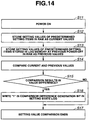
- step S2 the CPU 136 of the CCU 13 checks whether or not the setting state of each part of the endoscope apparatus has been changed.
- step S3 the CPU 136 determines whether or not the state change is based on a predetermined function operation executed by the user. If the determination results in "No”, then the process proceeds to step S4.
- step S6 the CPU 136 newly generates operation log data according to the operation log data format (see FIG. 5 ) of the system log data.
- step S7 the newly generated operation log data is stored in a predetermined area of the log memory 141. The process then returns to step S2.
- step S8 the CCU 13 newly generates setting state log data according to the setting state log data format (see FIG. 11 ) of the system log data.
- step S9 the newly generated setting state log data is stored in a predetermined area of the log memory 141. The process then returns to step S2.
- the CPU 136 stores each of actual setting values made last into the FLASH ROM 140 before completing the processing.
- step S12 the CPU 136 stores setting values of setting items stored in the FLASH ROM 140 (setting values of previous settings made last) into the SDRAM 139 as current values.
- step S13 the CPU 136 stores setting values of setting items of the setting state log data (last setting values in operational history) stored in the log memory 141, into the SDRAM 139 as previous values.
- step S14 the CPU 136 compares the current and previous values.
- step S15 the CPU 136 determines if the comparison results in any difference between the current and previous values. If the result is "No", then the process proceeds to step S17.
- step S15 determines the result is "Yes”
- step S16 the CPU 136 writes "1" into a comparison difference generation bit in the setting state log data of the system log data (by default, the comparison difference generation bit is set to "0").
- step S 17 the setting value comparison completes, completing the check-processing.
- this check-processing allows the setting state log data to have information of the comparison difference generation bit, in addition to the data shown in FIG. 5 .
- the endoscope system 1 of this embodiment includes two mechanism blocks as system functions: the user system (the medical facility 2) and the remote operation system (the support facility 4).
- the user system (the medical facility 2) includes: a log data read-out section 181 for reading out the setting state log data stored in the log memory 141; a log data sending section 182 for sending the setting state log data which is read out to the support system 5 of the remote operation system (the support facility 4); and a restoration operation activating section 183 for receiving a restore command from the support system 5 of the remote operation system (the support facility 4) and activating a restoration operation.
- the restoration operation by the restoration operation activating section 183 will be detailed later.
- the log data read-out section 181, the log data sending section 182, and the restoration operation activating section 183 are realized in a software manner by a program executed by the CPU 136.
- the remote operation system (the support facility 4) includes: a log data receiving section 202 for receiving the setting state log data from the log data sending section 182 of the user system (the medical facility 2); a log data analyzing section 203 for analyzing the received setting state log data; a communication requesting section 201 for requesting the log data read-out section 181 of the user system (the medical facility 2) to send the setting state log data, based on the control by the log data analyzing section 203; and a restore command sending section 204 for sending the restore command which is based on the analysis result of the log data analyzing section 203 to the restoration operation activating section 183 of the user system (the medical facility 2).
- the communication requesting section 201, the log data receiving section 202, the log data analyzing section 203, and the restore command sending section 204 are realized in a software manner by a program executed by a CPU (not shown) of the support system 5.
- the log data analyzing section 203 includes a log data displaying section 211 for displaying the setting state log data on the monitor 21, and a restore command generating/outputting section 212 for generating and outputting a restore command based on input from the keyboard 22.
- An LED control instruction command as an exemplary restore command has a data format configuration including Stx and CMD, as shown in FIG. 17 .
- Stx is header data (see FIG. 6 ).
- CMD is 1-byte data as shown in FIG. 18 and is accordingly represented as the commands as shown in FIG. 19 .
- the user system On receiving the LED control instruction command, the user system (the medical facility 2), i.e., the CPU 136, performs, e.g., turn-on control of the LED in the mode switch 150 on the operation panel 138.
- FIG. 20 an operational transition of the endoscope system of this embodiment based on a specific restore command is described. If an instrument setting is abnormal (in abnormal state) at the time of inspection, the user attempts to restore the instrument setting. However, the wide variety of setting items and the user engagement with the inspection disables the user to allot any time to analyze the setting abnormality. To counter such disability, the user system requests the remote operation system to analyze the setting abnormality. In response the remote operation system starts analyzing this abnormality using the setting state log data.
- Conceivable instrument abnormality states include those due to simple erroneous setting by the user, unsuitable setting for the observation mode, and abnormal instrument device.
- the remote operation system analyzes these abnormality states using the setting state log data.
- the remote operation system (the support facility 4) requests communication to the user system (the medical facility 2).
- the user system sends "Redy" to the remote operation system to establish communication between the user system and the remote operation system.
- the remote operation system On confirming the established communication, the remote operation system sends to the user system a log acquisition request command which requests the setting state log data. On receiving the log acquisition request command, the user system sends the setting state log data to the remote operation system according to the request.
- the remote operation system checks the received setting state log data by, e.g., check sum, etc., and sends an "OK" command which indicates normal reception to the user system. Upon receiving the "OK” command, the user system returns "ACK" to the remote operation system, thereby completing the sending/receiving of the setting state log data between the two systems.
- the remote operation system causes the setting state log data to be displayed on the monitor 21, which permits the maintenance worker operating the support system 5 to analyze the log data. For example, on finding that "the observation mode is set to "NBI mode” instead of the "normal observation mode” the user desires, then the maintenance worker inputs the analysis content using the keyboard 22.
- the support system 5 again generates, based on the inputted analysis content, a restore command, i.e., a command (0x0E for blinking the LED of the observation mode change-over switch of the LED control instruction command.
- the support system 5 then sends the generated command to the user system.
- the user system On receiving the LED control instruction command (command for blinking the LED of the observation mode change-over switch), the user system returns "ACK" to the remote operation system.
- the log data analyzing section 203 has a function configuration which is different from that in the first embodiment.
- the log data analyzing section 203 of this embodiment includes a data extracting section 213 for extracting setting state log data by comparison with a predetermined threshold value, as shown in FIG. 27 .
- the log data displaying section 211 displays the extraction result of the data extracting section 213 on the monitor 21 together with the setting state log data.
- the maintenance worker inputs to instruct the restore command generating/outputting section 212 to generate a reset command for instructing to reset the setting data, based on the extraction result of the data extracting section 213.
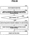
- the remote operation system starts a remote setting processing for the user system in step S31 by using the function of the log data analyzing section 203, as shown in FIG. 29 .
- step S39 the remote operation system confirms approval of the execution confirmation message from the user system. Having confirmed the approval from the user system, the remote operation system sends a setting resetting request command to the user system in step S40, and completes the remote setting processing in step S41.
- This embodiment can compare various setting values of the setting state log data with predetermined threshold values that correspond to, e.g., the observed situation for each observation mode and remotely reset the setting values that exceed the threshold values. Accordingly, this embodiment can, in addition to achieving the effect of the first embodiment, more easily and surely set the instrument into a state appropriate for the observed situation.
- this embodiment enables the user to check the settings and the like, through sound information and video information.
- the user is thus allowed to more easily monitor system instrument abnormalities and accordingly set the instrument into a state suitable for the observed situation than in the first embodiment.
Description
- The present invention relates to an endoscope system for processing signals using a plurality of instruments including an image pickup apparatus for picking up subject images.
- Endoscopes are widely used in medical and industrial fields. Recent years have seen wide use of endoscope apparatuses that include an endoscope equipped with an external television camera, which is constructed by attaching a television camera having image pickup means to the eye cup of the optical endoscope, or include an electronic endoscope having image pickup means built in the distal end portion of the endoscope, and display an image captured by the endoscope on the monitor to enable the user to perform observation and treatment while viewing the displayed image.
- These endoscope apparatuses employ a light source apparatus for supplying illumination light to the endoscope, a camera control unit (also referred to as "video processor") including an image signal processing circuit for displaying an endoscopic image, a TV monitor for displaying the endoscopic image, as well as a plurality of peripheral apparatuses such as, e.g., an insufflation apparatus and high frequency cauterization apparatus. An endoscope system that allows treatment or surgery to be carried out under endoscopic observation is thus constructed and has been practically used.
- In such an endoscope system, the plurality of peripheral apparatuses are typically connected to a system controller for concentrated control.
- The peripheral apparatuses of the endoscope system are equipped with electronic instruments such as an image pickup device and image processing means, precise mechanisms such as filter drive mechanism for sequentially irradiating light beams of RGB three colors, and consumable items such as a light source lamp, etc. Therefore the peripheral apparatuses normally require periodical maintenance by maintenance workers having related expertise.
- In many cases, however, a single maintenance worker is in charge of maintaining a plurality of electronic endoscopes and the endoscope processors. In some cases, the maintenance worker carries out the work of maintaining electronic endoscopes and endoscope processors that are remotely located. This situation has caused problems including high maintenance cost and inability to quickly address abnormalities that the electronic endoscopes and endoscope processor may have.
- To solve these problems, e.g.,
Japanese Patent Application Laid-Open Publication No. 2002-263063 - Further, e.g.,
Japanese Patent Application Laid-Open Publication No. 2005-111080 - These prior art techniques (
Japanese Patent Application Laid-Open Publication Nos. 2002-263063 2005-111080 - However, the image color tone may be changed by switching of observation modes (normal light, NBI, AFI) or change of color tone by user operation. Thus, an unintended user operation may erroneously change the image color tone, making the user have a sense of incongruity on the resulting image.
- In other words, a user, having a sense of incongruity on (the color tone of) the observation image, may not be able to identify whether the incongruity is due to an instrument abnormality or simply a setting changing operation not intended by the user. This situation deprives the user of an appropriate field service (e.g., a service man may be sent to check the instruments even if the instruments are not abnormal), disabling the user to use the instruments during the instrument checking and waiting time. The inspection efficiency is thus problematically decreased.
US 2002/126204 A1 concerns an endoscope system that is provided with an endoscope processor that processes an image signal output by an electronic endoscope, an endoscope controlling system connected to the endoscope processor to control operation of the endoscope processor or a device connected to the endoscope processor, an endoscope server that communicates with the endoscope controlling system through a first network, a service server that communicates with at least one of the endoscope processor and the device connected to the endoscope processor through a second network, and a surveillance circuit that surveys operation of the endoscope processor or the device connected to the endoscope processor. The endoscope controlling system transmits a surveying result to the endoscope server through the first network, and the endoscope server transmits the surveying result of the surveillance circuit to the service server through the second network.
US 2004/225185 A1 concerns an endoscope control system comprising a network server device which is provided with an interface for executing an external application software and stores a graphical user interface (GUI) which is a display information which is written in at least a server language and external application software, and a network interface. By doing this, it is possible to control remotely the endoscope device without connecting the endoscope device and the control section. - The present invention has been made in view of the above circumstances and has its object to provide an endoscope system that allows the user to take appropriate measures by monitoring whether the image deficiency is due to an instrument abnormality or whether the image merely appears deficient due to a setting change operation not intended by the user.
- That is, an object of the present invention is to provide an endoscope system that facilitates monitoring abnormalities in the system instrument settings and setting the instruments to an appropriate state suitable for the observed condition.
- An endoscope system according to the present invention includes the features of
claim 1. - As claimed according to a second aspect, a signal processing system comprises an endoscope for picking up an image of an inner body cavity by an image-pickup section; a light source for supplying illumination light to the endoscope; and a signal processing device including a plurality of signal processing sections for processing image-pickup signals from the endoscope, wherein the signal processing device includes: a control section for controlling, based on a setting value, operation of at least one of an internal circuit of the endoscope, an internal circuit of the signal processing section, and an internal circuit of the light source; a setting value changing section for changing the setting value; a log recording section for recording change history of the setting value as log data; a data sending section for sending the log data to an external instrument via a network; and a command receiving section for receiving a control command which is based on the log data from the external instrument via the network.
- According to the invetion, the control section controls the setting value changing section based on the control command receveid from the external instrument.
- As claimed further, there is provided a support facility for remotely supporting an operation of a user system, including the signal processing system according to first and second aspect of the invention as described above. The support facility comprises a log data receiving section for receiving, via a network, setting state log data, for example from the log data sending section of the signal processing system according to the first and second aspect described above; a log data analyzing section for analyzing the received setting state log data; and a restore command sending section for sending a restore command which is based on an analysis result of the log data analyzing section, for example to a restoration operation activating section of the signal processing system according to the first or second aspect described above.
-
-
FIG. 1 is a configuration diagram showing a configuration of an endoscope system according to a first embodiment of the present invention. -
FIG. 2 is a block diagram showing a configuration of a CCU ofFIG. 1 . -
FIG. 3 is a view showing a configuration of an operation panel ofFIG. 2 . -
FIG. 4 is a view showing a configuration of a keyboard ofFIG. 2 . -
FIG. 5 is a view showing a data format configuration of operation log data to be stored in a log memory ofFIG. 2 . -
FIG. 6 is a first view showing a specific data configuration of the data format configuration ofFIG. 5 . -
FIG. 7 is a second view showing a specific data configuration of the data format configuration ofFIG. 5 . -
FIG. 8 is a third view showing a specific data configuration of the data format configuration ofFIG. 5 . -
FIG. 9 is a fourth view showing a specific data configuration of the data format configuration ofFIG. 5 . -
FIG. 10 is a fifth view showing a specific data configuration of the data format configuration ofFIG. 5 . -
FIG. 11 is a view showing a data format configuration of setting state log data to be stored in the log memory ofFIG. 2 . -
FIG. 12 is a view showing a specific data configuration of the data format configuration ofFIG. 11 . -
FIG. 13 is a flow chart showing a flow of a processing for storing system log data in the CCU ofFIG. 2 . -
FIG. 14 is a flow chart showing a flow of a processing for checking the setting state of the system log data. -
FIG. 15 is a function block diagram showing a function of the endoscope system ofFIG. 1 . -
FIG. 16 is a function block diagram showing a function of a log data analyzing section ofFIG. 15 . -
FIG. 17 is a view showing a data format configuration of a restore command generated by the log data analyzing section ofFIG. 16 . -
FIG. 18 is a view showing a data configuration of a command body CMD of the restore command ofFIG. 17 . -
FIG. 19 is a view illustrating the content of the restore command ofFIG. 17 . -
FIG. 20 is a view illustrating operation transition of the endoscope system ofFIG. 1 . -
FIG. 21 is a view illustrating a manner of indication of a setting switch in the operation transition ofFIG. 20 . -
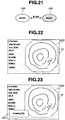
FIG. 22 is a view of an endoscopic image displayed on amonitor 12 ofFIG. 1 . -
FIG. 23 is a view showing a message indicating completion of setting which is superposed on the endoscopic image ofFIG. 22 . -
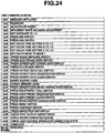
FIG. 24 is a view illustrating the content of a modification example of the restore command ofFIG. 17 . -
FIG. 25 is a view illustrating a modification example of the operation transition of the endoscope system ofFIG. 1 . -
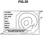
FIG. 26 is a view showing a message indicating the content of a restore command which is superposed on the endoscopic image ofFIG. 22 . -
FIG. 27 is a view showing a function configuration of a log data analyzing section according to a second embodiment of the present invention. -
FIG. 28 is a view showing a modification example of the function configuration of the log data analyzing section ofFIG. 27 . -
FIG. 29 is a view showing a flow of remote setting processing in a remote operation system by the log data analyzing section ofFIG. 27 or 28 . -
FIG. 30 is a view showing a flow of a remote resetting processing which follows the remote setting processing in the remote operation system ofFIG. 29 . -
FIG. 31 is a view showing a message which is superposedly displayed on the endoscopic image by the processing ofFIG. 30 . -
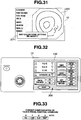
FIG. 32 is a view showing a configuration of an operation panel of a CCU according to a third embodiment of the present invention. -
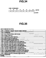
FIG. 33 is a view showing a data format configuration of a touch panel control command for a touch panel ofFIG. 32 . -
FIG. 34 is a first view illustrating the touch panel control command ofFIG. 33 . -
FIG. 35 is a second view illustrating the touch panel control command ofFIG. 33 . -
FIG. 36 is a third view illustrating the touch panel control command ofFIG. 33 . -
FIG. 37 is a fourth view illustrating the touch panel control command ofFIG. 33 . -
FIG. 38 is a view showing an operation transition of the endoscope system using the touch panel control command ofFIG. 33 . -
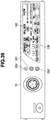
FIG. 39 is a view showing a configuration of an operation panel of a CCU according to a fourth embodiment of the present invention. -
FIG. 40 is a block diagram showing a circuit configuration of the CCU ofFIG. 39 . -
FIG. 41 is a view showing an image window superposed on the endoscopic image displayed on a monitor ofFIG. 40 . - Referring to the drawings, embodiments of the present invention are described below.
-
FIGS. 1 to 26 relate to a first embodiment of the present invention.FIG. 1 is a configuration diagram showing a configuration of an endoscope system.FIG. 2 is a block diagram showing a configuration of a CCU ofFIG. 1 .FIG. 3 is a view showing a configuration of an operation panel ofFIG. 2 .FIG. 4 is a view showing a configuration of a keyboard ofFIG. 2 .FIG. 5 is a view showing a data format configuration of operation log data to be stored in a log memory ofFIG. 2 .FIG. 6 is a first view showing a specific data configuration of the data format configuration ofFIG. 5 .FIG. 7 is a second view showing a specific data configuration of the data format configuration ofFIG. 5 .FIG. 8 is a third view showing a specific data configuration of the data format configuration ofFIG. 5 .FIG. 9 is a fourth view showing a specific data configuration of the data format configuration ofFIG. 5 .FIG. 10 is a fifth view showing a specific data configuration of the data format configuration ofFIG. 5 .FIG. 11 is a view showing a data format configuration of setting state log data to be stored in the log memory ofFIG. 2 .FIG. 12 is a view showing a specific data configuration of the data format configuration ofFIG. 11 .FIG. 13 is a flow chart showing a flow of a processing for storing of system log data in the CCU ofFIG. 2 .FIG. 14 is a flow chart showing a flow of a processing for checking the setting state of the system log data.FIG. 15 is a function block diagram showing a function of the endoscope system ofFIG. 1 .FIG. 16 is a function block diagram showing a function of a log data analyzing section ofFIG. 15 .FIG. 17 is a view showing a data format configuration of a restore command generated by a log data analyzing section ofFIG. 16 .FIG. 18 is a view showing a data configuration of a command body CMD of the restore command ofFIG. 17 .FIG. 19 is a view illustrating the content of the restore command ofFIG. 17 .FIG. 20 is a view illustrating operation transition of the endoscope system ofFIG. 1 .FIG. 21 is a view illustrating a manner of indication of a setting switch in the operation transition ofFIG. 20 .FIG. 22 is a view of an endoscopic image displayed on amonitor 12 ofFIG. 1 .FIG. 23 is a view showing a message indicating completion of setting which is superposed on the endoscopic image ofFIG. 22 .FIG. 24 is a view illustrating the content of a modification example of the restore command ofFIG. 17 .FIG. 25 is a view illustrating a modification example of the operation transition of the endoscope system ofFIG. 1 .FIG. 26 is a view showing a message indicating the content of a restore command which is superposed on the endoscopic image ofFIG. 22 . - As shown in
FIG. 1 , anendoscope system 1 of this embodiment includes: a plurality ofendoscope apparatuses medical facility 2 which is a user system; and asupport system 5 provided in asupport facility 4 which is a remote operation system located away from themedical facility 2. The plurality ofendoscope apparatuses support system 5 are communicatably connected to each other via LAN (Local Area Network) 6 and WAN (Wide Area Network) 7. - The
endoscope apparatus 3A includes anendoscope 10 for picking up images of an intra-body cavity observation region; alight source apparatus 11 for supplying illumination light to theendoscope 10; and a camera control unit (hereinafter "CCU") 13 for displaying an observation region image picked up by theendoscope 10 on amonitor 12 as an endoscopic image. TheCCU 13 is connected with akeyboard 14 which is used to input data. Theendoscope apparatus 3B also has the same configuration as theendoscope apparatus 3A. - The
support system 5 is configured by a personal computer (PC), etc., which includes a PCmain body 20, monitor 21, andkeyboard 22. - As shown in
FIG. 2 , theCCU 13 is detachably connectable via aconnector 131 a with aconnector 105 of theendoscope 10. - The
endoscope 10 has aninsertion portion 101 to be inserted into the body cavity. In a distal end of theinsertion portion 101, there are included ascope CCD 102 for image pick-up of the observation region; aswitch 103 for instructing various operations (such as bending operation and release operation) which is provided on an operation portion at a proximal end of theinsertion portion 101; ascope CPU 104 for controlling each part of theendoscope 10 and managing endoscope type information, etc., which is provided in the operation portion at the proximal end of theinsertion portion 101. - The
CCU 13 includes apreprocess section 131 which is inputted with an image-pickup signal from thescope CCD 102 of theendoscope 10 via theconnectors preprocess section 131 is a processing section for executing known analogue processings including noise removal processing, correlative double sampling processing, and white balance processing, on the image-pickup signal from thescope CCD 102. - The analogue signal processed by the
preprocess section 131 is converted to a digital signal by an A/D conversion section 132 and inputted to a digital videosignal processing section 133 in the subsequent stage. - The digital video
signal processing section 133 executes known image (video) digital processings (such as color tone correction, γ correction, and expansion/reduction processing) on the digital signal from the A/D conversion section 132 using aVRAM 135, etc. The digitally processed digital video signal is converted to an analogue signal by a D/A conversion section 134. This converted analogue signal is displayed on themonitor 12 as an endoscopic image. - The
CCU 13 further includes aCPU 136. TheCPU 136 sends/receives data to/from thescope CPU 104 and receives inputs of instruction signals from theswitch 103 of the endoscope via theconnectors - The
CPU 136 is connected to the light source apparatus 11 (seeFIG. 1 ) via theconnector 131a and sends/receives information to/from a light source CPU (not shown) in thelight source apparatus 11. TheCPU 136 can thereby acquire light source history information (log data) including setting information of thelight source apparatus 11 such as, e.g., light adjustment information and use-history of the light source lamp (not shown). - The
CPU 136 is further connected to thekeyboard 14 via aPCI bus bridge 143 and aUSB controller 144. TheCPU 136 can thus receive information inputted using thekeyboard 14 and have various information displayed on thekeyboard 14. TheCCU 13 is furthermore connected to the LAN 6 (seeFIG. 1 ) via thePCI bus bridge 143 and an Ethernet (registered trademark)controller 145. - The
CPU 136 is connected to thePCI bus bridge 143 and theEthernet controller 145 via an internal bus. - The
CPU 136 is also connected to anSDRAM 139,FLASH ROM 140, logmemory 141 andcompand processing section 142 via the internal bus. - The
CPU 136 controls, e.g., thecompand processing section 142 using theSDRAM 139, performs a compand processing on the digital image processed by the digital videosignal processing section 133, and records the resultant image into theFLASH ROM 140. - The
CPU 136 moreover saves and manages in thelog memory 141, as system log data, history information (log data) on settings and operations made with theoperation panel 138, thekeyboard 14, etc.; information on various settings/operations of the endoscope 10 (acquired from thescope CPU 104 of the endoscope 10); or information on various settings/operations of thelight source apparatus 11, which is produced in various processings in parts of theCCU 13. - Conventionally, the system log data has generally been stored and saved in the
log memory 141 to be used by theCPU 136 to manage the system settings when activating the endoscope apparatus, as well as by the user to use the inspection flow as data for checking the executed procedures and for education after completion of an inspection with the endoscope apparatus. - As shown in
FIG. 3 , theoperation panel 138 is provided on a front surface of theCCU 13. On theoperation panel 138, various setting switches are provided. For example, amode switch 150 shown inFIG. 3 is a switch for selecting one of observation modes, which are processable by theCCU 13. In this embodiment, theCCU 13 can select normal observation mode (Normal) by visible light, first special observation mode (NBI) by narrow band light, or second special observation mode (PDD) by fluorescent light, through operation of themode switch 150. The mode setting state is sent to theCPU 136 via an I/O port 137. - As shown in
FIG. 4 , thekeyboard 14 includes above a normal (known) key input portion, adisplay panel portion 14A on which various states can be directly inputted and displayed. The setting state of thedisplay panel portion 14A is sent to theCPU 136 via theUSB controller 144. The manner of indication of themode switch 150a on thedisplay panel portion 14A is controllable by theCPU 136 via theUSB controller 144, as the manner of indication of theoperation panel 138 is. - Next is described system log data that is saved in the
log memory 141 by theCPU 136. - The system log data includes operation log data and setting state log data. The
CPU 136 stores the operation log data and setting state log data in a predetermined area of thelog memory 141. - Specifically, the operation log data has a data format configuration as shown in
FIG. 5 , including Stx, Item, MO, DD, HH, MT, SEC, Len and Data. - Stx is header data as shown in
FIG. 6 . Item is data extension (seeFIG. 10 ) for identifying data classification (setting/operation classification) as shown inFIG. 7 . MO (month), DD (date), HH (hour), MT (minute) and SEC (second) are time stamp data to show the time of day when an operation is performed, as shown inFIG. 8 . Len shows the data length of the operation log data as shown inFIG. 9 . Further, Data is the data body of the operation log data, having a data configuration which is classified by Item (extension), as shown inFIG. 10 . - The setting state log data also includes Stx, Item, MO, DD, HH, MT, SEC, Len and Data, as shown in
FIG. 11 . Data configuration of Stx, Item, MO, DD, HH, MT, SEC and Len is the same as of the operation log data. Data is the data body of the setting state log data, having a data configuration which is classified by Item (extension) as shown inFIG. 12 . - An action of this embodiment thus configured is described below.
- As shown in
FIG. 13 , when power is turned on in step S1, then in step S2 theCPU 136 of theCCU 13 checks whether or not the setting state of each part of the endoscope apparatus has been changed. - If the checking results in "Yes", then in step S3 the
CPU 136 determines whether or not the state change is based on a predetermined function operation executed by the user. If the determination results in "No", then the process proceeds to step S4. - In step S4, the
CPU 136 determines whether or not the state change is based on a predetermined setting change executed by the user. If the determination results in "No", then the process proceeds to step S5. In step S5, log is not generated for the system log data. The process then returns to step S2. - If in step S3 the determination results in "Yes", then in step S6 the
CPU 136 newly generates operation log data according to the operation log data format (seeFIG. 5 ) of the system log data. In step S7, the newly generated operation log data is stored in a predetermined area of thelog memory 141. The process then returns to step S2. - If in step S4 the determination results in "Yes", then in step S8 the
CCU 13 newly generates setting state log data according to the setting state log data format (seeFIG. 11 ) of the system log data. In step S9, the newly generated setting state log data is stored in a predetermined area of thelog memory 141. The process then returns to step S2. - In this embodiment, when the
endoscope apparatus 3A completes an inspection, theCPU 136 stores each of actual setting values made last into theFLASH ROM 140 before completing the processing. - The
CPU 136 is thus enabled to execute, upon power-on, the check-processing for checking the setting state of the system log data as shown inFIG. 14 before the above processing (FIG. 13 ). - Specifically, as shown in
FIG. 14 , upon power-on in step S11, then in step S12 theCPU 136 stores setting values of setting items stored in the FLASH ROM 140 (setting values of previous settings made last) into theSDRAM 139 as current values. - Next in step S13, the
CPU 136 stores setting values of setting items of the setting state log data (last setting values in operational history) stored in thelog memory 141, into theSDRAM 139 as previous values. - Subsequently in step S14, the
CPU 136 compares the current and previous values. In step S15, theCPU 136 determines if the comparison results in any difference between the current and previous values. If the result is "No", then the process proceeds to step S17. - If step S15 determines the result is "Yes", then in step S16 the
CPU 136 writes "1" into a comparison difference generation bit in the setting state log data of the system log data (by default, the comparison difference generation bit is set to "0"). Instep S 17, the setting value comparison completes, completing the check-processing. - Thus, executing this check-processing allows the setting state log data to have information of the comparison difference generation bit, in addition to the data shown in
FIG. 5 . - As shown in
FIG. 15 , theendoscope system 1 of this embodiment includes two mechanism blocks as system functions: the user system (the medical facility 2) and the remote operation system (the support facility 4). - That is, as shown in
FIG. 15 , the user system (the medical facility 2) includes: a log data read-outsection 181 for reading out the setting state log data stored in thelog memory 141; a logdata sending section 182 for sending the setting state log data which is read out to thesupport system 5 of the remote operation system (the support facility 4); and a restorationoperation activating section 183 for receiving a restore command from thesupport system 5 of the remote operation system (the support facility 4) and activating a restoration operation. The restoration operation by the restorationoperation activating section 183 will be detailed later. - The log data read-out
section 181, the logdata sending section 182, and the restorationoperation activating section 183 are realized in a software manner by a program executed by theCPU 136. - On the other hand, the remote operation system (the support facility 4) includes: a log
data receiving section 202 for receiving the setting state log data from the logdata sending section 182 of the user system (the medical facility 2); a logdata analyzing section 203 for analyzing the received setting state log data; acommunication requesting section 201 for requesting the log data read-outsection 181 of the user system (the medical facility 2) to send the setting state log data, based on the control by the logdata analyzing section 203; and a restorecommand sending section 204 for sending the restore command which is based on the analysis result of the logdata analyzing section 203 to the restorationoperation activating section 183 of the user system (the medical facility 2). - The
communication requesting section 201, the logdata receiving section 202, the logdata analyzing section 203, and the restorecommand sending section 204 are realized in a software manner by a program executed by a CPU (not shown) of thesupport system 5. - As shown in
FIG. 16 , the logdata analyzing section 203 includes a logdata displaying section 211 for displaying the setting state log data on themonitor 21, and a restore command generating/outputting section 212 for generating and outputting a restore command based on input from thekeyboard 22. - In this embodiment, the log
data analyzing section 203 is configured to cause the setting state log data to be displayed on themonitor 21 of thesupport system 5, so that the maintenance worker can operate thesupport system 5 to analyze the log data and, based on the analysis result, input countermeasure information to thesupport system 5 using thekeyboard 22. The restore command generating/outputting section 212 generates a restore command based on the countermeasure information. The generated restore command is then outputted to the user system (the medical facility 2). - An LED control instruction command as an exemplary restore command has a data format configuration including Stx and CMD, as shown in
FIG. 17 . Stx is header data (seeFIG. 6 ). CMD is 1-byte data as shown inFIG. 18 and is accordingly represented as the commands as shown inFIG. 19 . - On receiving the LED control instruction command, the user system (the medical facility 2), i.e., the
CPU 136, performs, e.g., turn-on control of the LED in themode switch 150 on theoperation panel 138. - Now referring to
FIG. 20 , an operational transition of the endoscope system of this embodiment based on a specific restore command is described. If an instrument setting is abnormal (in abnormal state) at the time of inspection, the user attempts to restore the instrument setting. However, the wide variety of setting items and the user engagement with the inspection disables the user to allot any time to analyze the setting abnormality. To counter such disability, the user system requests the remote operation system to analyze the setting abnormality. In response the remote operation system starts analyzing this abnormality using the setting state log data. - In this analysis request, for example the following processings are performed through communication, telephone, etc. Conceivable instrument abnormality states include those due to simple erroneous setting by the user, unsuitable setting for the observation mode, and abnormal instrument device. The remote operation system analyzes these abnormality states using the setting state log data.
- The remote operation system (the support facility 4) requests communication to the user system (the medical facility 2). The user system sends "Redy" to the remote operation system to establish communication between the user system and the remote operation system.
- On confirming the established communication, the remote operation system sends to the user system a log acquisition request command which requests the setting state log data. On receiving the log acquisition request command, the user system sends the setting state log data to the remote operation system according to the request.
- The remote operation system checks the received setting state log data by, e.g., check sum, etc., and sends an "OK" command which indicates normal reception to the user system. Upon receiving the "OK" command, the user system returns "ACK" to the remote operation system, thereby completing the sending/receiving of the setting state log data between the two systems.
- The remote operation system causes the setting state log data to be displayed on the
monitor 21, which permits the maintenance worker operating thesupport system 5 to analyze the log data. For example, on finding that "the observation mode is set to "NBI mode" instead of the "normal observation mode" the user desires, then the maintenance worker inputs the analysis content using thekeyboard 22. - In the remote operation system, based on the inputted analysis content, the
support system 5 generates a restore command, i.e., a command (0x0E for blinking the LED of the observation mode change-over switch of the LED control instruction command. Thesupport system 5 then sends the generated command to the user system. On receiving the LED control instruction command (command for blinking the LED of the observation mode change-over switch), the user system returns "ACK" to the remote operation system. - The LED control instruction command (command for blinking the LED of the observation mode change-over switch) blinks the
mode switch 150, which is the observation mode change-over switch, on theoperation panel 138 of the user system as shown inFIG. 21 . The blinking notifies an erroneous observation mode setting to the user, who in response operates themode switch 150. - This user operation of the
mode switch 150 is recorded as new log data in the setting state log data in thelog memory 141. - In this embodiment, the
mode switch 150 is operated to allow for toggle-like switching of three observation modes: "normal observation mode" → "NBI (narrow band observation) mode" → "PDD (fluorescent light observation) mode" → "normal observation mode" and the same. - In this "
user operation 1" section, however, the observation mode is changed from the NBI mode to PDD mode but is not yet changed to the "normal observation mode" that the user desires. - The remote operation system again sends to the user system the log acquisition request command that requests the setting state log data. The user system receives the log acquisition request command, and sends the setting state log data to the remote operation system in response to the request.
- In the remote operation system, the setting state log data is displayed on the
monitor 21, which permits the maintenance worker operating thesupport system 5 to analyze the log data. On finding that, e.g., "the observation mode setting has been changed from "NBI mode" to "PDD mode", the maintenance worker inputs the analysis content using thekeyboard 22. - In the remote operation system, the
support system 5 again generates, based on the inputted analysis content, a restore command, i.e., a command (0x0E for blinking the LED of the observation mode change-over switch of the LED control instruction command. Thesupport system 5 then sends the generated command to the user system. On receiving the LED control instruction command (command for blinking the LED of the observation mode change-over switch), the user system returns "ACK" to the remote operation system. - The LED control instruction command (command for blinking the LED of the observation mode change-over switch) blinks the
mode switch 150, which is the observation mode change-over switch, on theoperation panel 138 of the user system as shown inFIG. 21 . The blinking notifies the user that there is still an erroneous observation mode setting. The user in response operates themode switch 150. - This user operation of the
mode switch 150 is recorded as new log data in the setting state log data in thelog memory 141. - By this "
user operation 2", the observation mode is changed to the "normal observation mode" that the user desires. - The remote operation system again sends to the user system the log acquisition request command which requests the setting state log data. On receiving the log acquisition request command, the user system sends the setting state log data to the remote operation system in response to the request.
- In the remote operation system, the setting state log data is displayed on the
monitor 21, which permits the maintenance worker operating thesupport system 5 to analyze the log data. On finding that, e.g., "the observation mode setting has been changed from "PDD mode" to "normal observation mode" the user desires, the maintenance worker inputs "analysis complete" using thekeyboard 22. - In the remote operation system, the
support system 5 generates a setting-complete message display command based on the analysis complete input. Thesupport system 5 sends the generated command to the user system. On receiving this setting-complete message display command, the user system returns "ACK" to the remote operation system. - It is noted that the user system which has received the message display command can cause a
message window 221 reading "Complete!" as shown inFIG. 23 to be superposedly displayed on themonitor 12 displaying, e.g., anendoscopic image 220 as shown inFIG. 22 . The user is thus enabled to visually recognize the completion of setting. - It is further noted that if the check-processing described in
FIG. 14 indicates that the comparison difference generation bit in the setting state log data is set to "1", then the maintenance worker can determine this setting as an abnormal state due to an instrument device abnormality. The maintenance worker notifies the user system of the instrument abnormality, contacting to accept repairing of the instrument. - As mentioned above, this embodiment can perform restoration from an abnormal setting of the endoscope apparatus by sending the setting state log data, which has conventionally and generally been stored in the
log memory 141, from the user system to the remote operation system, and furthermore a restore command based on the setting state log data from the remote operation system to the user system. It is thus enabled to easily monitor system instrument abnormalities and set the instruments into a state appropriate for the observed situation, without any specific need to provide means for monitoring each instrument of the endoscope apparatus. - It should be noted that the restore command is not limited to the LED control instruction command shown in
FIG. 19 . Alternatively the command may be as CMD, e.g., a message display command which is superposely displayed on themonitor 12 displaying theendoscopic image 220, as shown inFIG. 24 . In this case, the operational transition of the endoscope system is as shown inFIG. 25 . In this transition, instead of the LED control instruction command being sent inTransitions FIG. 20 , the message display command is sent from the remote operation system to the user system. - As a result, instead of blinking the LED of the observation mode change-over switch shown in
FIG. 21 , themessage window 221 reading, e.g., "Press the observation mode change-over switch" is superposedly displayed on the endoscopic image as shown inFIG. 26 , like themessage window 221 reading "Complete!" shown inFIG. 23 . Such displaying enables the user to visually recognize an erroneous observation mode setting, achieving the same action and effect as described above in this embodiment. -
FIGS. 27 to 31 relate to a second embodiment of the present invention.FIG. 27 is a view showing a function configuration of a log data analyzing section.FIG. 28 is a view showing a modification example of the function configuration of the log data analyzing section ofFIG. 27 .FIG. 29 is a view showing a flow of remote setting processing in a remote operation system by the log data analyzing section ofFIG. 27 or 28 .FIG. 30 is a view showing a flow of a remote resetting processing to follow the remote setting processing in the remote operation system ofFIG. 29 .FIG. 31 is a view showing a message which is superposedly displayed on the endoscopic image by the processing ofFIG. 30 . - Since the second embodiment is almost the same as the first embodiment, only differences are described. The same components are denoted with the same reference symbols, omitting their descriptions.
- In this embodiment, the log
data analyzing section 203 has a function configuration which is different from that in the first embodiment. The logdata analyzing section 203 of this embodiment includes adata extracting section 213 for extracting setting state log data by comparison with a predetermined threshold value, as shown inFIG. 27 . The logdata displaying section 211 displays the extraction result of thedata extracting section 213 on themonitor 21 together with the setting state log data. In this embodiment, the maintenance worker inputs to instruct the restore command generating/outputting section 212 to generate a reset command for instructing to reset the setting data, based on the extraction result of thedata extracting section 213. - It should be noted that the log
data analyzing section 203 may further include adata judging section 214 for judging an extraction result of thedata extracting section 213 as shown inFig. 28 , so that a reset command based on the judging result of thedata judging section 214 is outputted from the restore command generating/outputting section 212. - In this embodiment thus configured, the remote operation system starts a remote setting processing for the user system in step S31 by using the function of the log
data analyzing section 203, as shown inFIG. 29 . - The remote operation system in step S32 requests the user system for the setting state log data, and in step S33 receives the setting state log data from the user system.
- Next in step S34, the remote operation system compares various setting values of the received setting state log data with respective threshold values corresponding to, e.g., the observed situation for each observation mode. In step S35, the remote operation system judges whether or not there is a setting item whose setting value exceeds the threshold value.
- It is noted that this judgment is performed by the maintenance worker in the configuration of
FIG. 27 , and by thedata judging section 214 in the configuration ofFIG. 28 . - If it is judged that there is a setting item whose setting value exceeds the threshold value, then in step S36 the remote operation system sends a warning message display command to the user system. This warning message display command implements in the user system an action similar to the action by the message display command in the first embodiment (see
FIG. 24 ). That is, on receiving the warning message display command, the user system superposedly displays a warning message on the endoscopic image in step S37. - Following the displaying of the warning message, in step S38 the remote operation system further sends to the user system a message display command for displaying an execution confirmation message as to whether or not to change the setting value to the standard value. The execution confirmation message is thus superposedly displayed on the endoscopic image.
- Subsequently in step S39, the remote operation system confirms approval of the execution confirmation message from the user system. Having confirmed the approval from the user system, the remote operation system sends a setting resetting request command to the user system in step S40, and completes the remote setting processing in step S41.
- Next, a processing for remotely resetting the settings is described. The remote operation system starts the remote resetting processing in step S51. Then in step S52, the system displays in the user system an execution confirmation message as to whether or not to change (reset) the setting value to the standard value.
- Specifically, the remote operation system superposedly displays the
message window 221 reading, e.g., "May color tone setting be reset?" on theendoscopic image 220 displayed on themonitor 12, as shown inFIG. 31 . - If the remote operation system confirms an "OK" input pressed for reset approval from the user system in step S53, then sends an initialization request command to the user system in step S54, resets the predetermined various setting values in the user system in step S55, and completes the remote resetting processing in step S56.
- This embodiment can compare various setting values of the setting state log data with predetermined threshold values that correspond to, e.g., the observed situation for each observation mode and remotely reset the setting values that exceed the threshold values. Accordingly, this embodiment can, in addition to achieving the effect of the first embodiment, more easily and surely set the instrument into a state appropriate for the observed situation.
-
FIGS. 32 to 38 relate to a third embodiment of the present invention.FIG. 32 is a view showing a configuration of an operation panel of a CCU.FIG. 33 is a view showing a data format configuration of a touch panel control command for a touch panel ofFIG. 32 .FIG. 34 is a first view illustrating the touch panel control command ofFIG. 33 .FIG. 35 is a second view illustrating the touch panel control command ofFIG. 33 .FIG. 36 is a third view illustrating the touch panel control command ofFIG. 33 .FIG. 37 is a fourth view illustrating the touch panel control command ofFIG. 33 .FIG. 38 is a view showing an operation transition of the endoscope system using the touch panel control command ofFIG. 33 . - Since the third embodiment is almost the same as the first embodiment, only differences are described. The same components are denoted with the same reference symbols, omitting their descriptions.
- In this embodiment, the operational transition of the endoscope system is as shown in
FIG. 38 . In this transition, instead of the LED control instruction command being sent inTransitions FIG. 20 , a touch panel control command is sent from the remote operation system to the user system to change the manner of indication of atouch panel 300. The user is thus allowed to visually recognize an erroneous setting as in first embodiment. - Thus, configuring the
operation panel 138 with thetouch panel 300, this embodiment enables the user to visually recognize the setting state of the setting values in a more flexible manner of indication, in addition to achieving the effect of the first embodiment. -
FIGS. 39 to 41 relate to a fourth embodiment of the present invention.FIG. 39 is a view showing a configuration of an operation panel of a CCU.FIG. 40 is a block diagram showing a circuit configuration of the CCU ofFIG. 39 .FIG. 41 is a view showing an image window superposed on the endoscopic image displayed on a monitor ofFIG. 40 . - Since the fourth embodiment is almost the same as the first embodiment, only differences are described. The same components are denoted with the same reference symbols, omitting their descriptions.
- In this embodiment, a
sound collecting microphone 351, aspeaker 352, and amain body CCD 353 are provided on theoperation panel 138 of theCCU 13, as shown inFIG. 39 . - As shown in
FIG. 40 , in theCCU 13, an A/D converter 361 converts user sound signal from thesound collecting microphone 351 to digital signals, which are then subjected to a known sound recognition processing by a soundinput processing section 371. The processed signals are subsequently passed via aPCI bus bridge 143 to be captured by theCPU 136. TheCPU 136 thus obtains sound information of the user from thesound collecting microphone 351. Signals of user images picked up by themain body CCD 353 are passed through the same processing path as of the image-pickup signals of thescope CCD 102 via the digital videosignal processing section 133 to be captured by theCPU 136 as user video information. The user sound information and video information captured by theCPU 136 are passed through thePCI bus bridge 143 and outputted by the Ethernet (registered trademark)controller 145 to theLAN 6. The outputted information is further transmitted to the remote operation system via theWAN 7. - Likewise, sound information and video information from the remote operation system are captured into the
CPU 136 via the WAN7 and theLAN 6. The sound information from the remote operation system is subjected to a known sound synthesizing processing by a soundoutput processing section 372. The processed sound information is sent to a D/A converter 362. The converted sound information is then outputted as sound from thespeaker 352. The video information from the remote operation system is processed by the digital videosignal processing section 133. The processed video information is superposedly displayed as animage window 221A on theendoscopic image 220, as shown inFIG. 41 . - As described above, this embodiment enables the user to check the settings and the like, through sound information and video information. The user is thus allowed to more easily monitor system instrument abnormalities and accordingly set the instrument into a state suitable for the observed situation than in the first embodiment.
- The present invention is not limited to the above-described embodiments but may be variously changed and modified without changing the scope of the present invention.
Claims (9)
- An endoscope system (1) comprising a user system (2) and a remote operation system (4), comprising:an endoscope (3A, 3B) provided in the user system (2) and configured to pick up an image of a subject in a body cavity by an image-pickup section (102);a signal processing section (13) provided in the user system (2) and configured to output the image of the subject obtained by processing image-pickup signals from the endoscope (3A, 3B);a light source (11) provided in the user system (2) and configured to supply illumination light for illuminating the subject to the endoscope (3A, 3B);a setting value changing section (138, 150; 14, 150a; 138, 300) provided in the user system (2) and configured to perform operation for changing a setting value related to operation of at least one of the endoscope (3A, 3B), the signal processing section (13), and the light source (11);a control section (136-138, 150; 14, 136, 143, 144, 150a; 136-138, 300) configured to control the endoscope (3A, 3B), the signal processing section (13), and the light source (11), based on the setting value set according to operation of the setting value changing section (138, 150; 14, 150a; 138, 300);a log recording section (141) provided in the user system (2) and configured to record change history of the setting value as setting state log data;a data sending section (143, 145, 182, 202, 203) provided in the user system (2) and configured to send the setting state log data to the remote operation system (4) via a network (6, 7); anda command receiving section (143, 145, 203, 204, 183) configured to receive a control command which is based on the setting state log data from the remote operation system (4) via the network (6, 7),characterized in thatthe control section (136-138, 150; 14, 136, 143, 144, 150a; 136-138, 300) is adapted to control the setting value changing section (138, 150; 14, 150a; 138, 300) based on the control command received from the remote operation system (4), andthe remote operation system (4) comprises a log data analyzing section (203) configured to analyze the received setting state log data and generate the control command.
- The endoscope system (1) according to claim 1,
wherein the control section is adapted to store, in a memory, the setting value at the time of completion of an inspection in the user system (2), as a current value, to store in the memory, a last setting value in the change history recorded in the setting state log data, as a previous value, and to compare the current value and the previous value stored in the memory. - The endoscope system (1) according to claim 2, wherein the control section is adapted to perform processing for writing, into the setting state log data, bit data with which determination whether there is a difference between the current value and the previous value is possible, based on a comparison result of the comparison of the current value and the previous value.
- The endoscope system (1) according to any one of the claims 1 to 3, further comprising a log data read-out section (181) provided in the user system (2) and configured to read out the setting state log data stored in the log recording section (141).
- The endoscope system (1) according to Claim 1, wherein the user system (2) further comprises an identification display section (138, 150; 14A, 150; 138, 300) configured to enable a user to identify a setting item of which setting value is to be changed,and
the control section is configured to control a manner of indication of the identification display section based on the control command. - The endoscope system (1) according to Claim 5, wherein the manner of indication of the identification display section is a manner of light emission of a light emission section provided near a setting change switch (150A) in the setting value changing section.
- The endoscope system (1) according to Claim 6, wherein the light emission section is an LED and the manner of light emission is one of turning on, blinking, and turning off the LED.
- The endoscope system (1) according to any one of Claims 1 to 7, wherein, when one setting unit included in the setting state log data has exceeded a predetermined threshold, the remote operation system (4) is configured to send, as the control command, a reset command for resetting the one setting value and changing the one setting value to a standard value to the user system (2).
- The endoscope system (1) according to Claim 8, wherein the remote operation system (4) is configured to, before sending the reset command to the user system (2), sequentially send to the user system (2) a first message display command for causing a warning message for giving warning that the one setting value has exceeded the predetermined threshold to be superposedly displayed on the image and a second message display command for causing confirmation message for confirming whether or not to execute initialization of the one setting value to be superposedly displayed on the image.
Applications Claiming Priority (1)
| Application Number | Priority Date | Filing Date | Title |
|---|---|---|---|
| JP2008034995A JP2009189654A (en) | 2008-02-15 | 2008-02-15 | Signal processing system |
Publications (3)
| Publication Number | Publication Date |
|---|---|
| EP2090919A2 EP2090919A2 (en) | 2009-08-19 |
| EP2090919A3 EP2090919A3 (en) | 2009-11-18 |
| EP2090919B1 true EP2090919B1 (en) | 2017-07-12 |
Family
ID=40637197
Family Applications (1)
| Application Number | Title | Priority Date | Filing Date |
|---|---|---|---|
| EP09000681.8A Expired - Fee Related EP2090919B1 (en) | 2008-02-15 | 2009-01-19 | Signal processing system |
Country Status (4)
| Country | Link |
|---|---|
| US (1) | US8284244B2 (en) |
| EP (1) | EP2090919B1 (en) |
| JP (1) | JP2009189654A (en) |
| CN (1) | CN101507598A (en) |
Families Citing this family (6)
| Publication number | Priority date | Publication date | Assignee | Title |
|---|---|---|---|---|
| CN103315698A (en) * | 2013-06-19 | 2013-09-25 | 上海世音光电仪器有限公司 | Remote control service system for endoscope camera system |
| JP5938384B2 (en) * | 2013-10-31 | 2016-06-22 | 京セラドキュメントソリューションズ株式会社 | Electronics |
| JP5932188B1 (en) * | 2014-07-29 | 2016-06-08 | オリンパス株式会社 | Video processor for endoscope and endoscope system having the same |
| CN105808396A (en) * | 2016-03-04 | 2016-07-27 | 浙江大华技术股份有限公司 | Chip debugging device, debugging method and SOC (System of Chip) chip system |
| CN109843206B (en) | 2016-09-20 | 2021-07-13 | 奥林巴斯株式会社 | Centralized control device |
| JPWO2019208654A1 (en) * | 2018-04-27 | 2021-04-30 | 富士フイルム株式会社 | Endoscopy information analyzer, endoscopy information input support system, and endoscopy information analysis method |
Family Cites Families (21)
| Publication number | Priority date | Publication date | Assignee | Title |
|---|---|---|---|---|
| JP2917995B2 (en) * | 1988-05-25 | 1999-07-12 | 株式会社東芝 | Endoscope device |
| US5164824A (en) * | 1990-10-12 | 1992-11-17 | Olympus Optical Co., Ltd. | Image freezing signal-processing apparatus |
| US6078681A (en) * | 1996-03-18 | 2000-06-20 | Marine Biological Laboratory | Analytical imaging system and process |
| US6293911B1 (en) * | 1996-11-20 | 2001-09-25 | Olympus Optical Co., Ltd. | Fluorescent endoscope system enabling simultaneous normal light observation and fluorescence observation in infrared spectrum |
| US7179222B2 (en) * | 1996-11-20 | 2007-02-20 | Olympus Corporation | Fluorescent endoscope system enabling simultaneous achievement of normal light observation based on reflected light and fluorescence observation based on light with wavelengths in infrared spectrum |
| US6322496B1 (en) * | 1998-11-06 | 2001-11-27 | Asahi Kogaku Kogyo Kabushiki Kaisha | Electronic endoscope system |
| JP3809026B2 (en) * | 1999-02-02 | 2006-08-16 | ペンタックス株式会社 | Endoscope air supply safety device |
| JP3394742B2 (en) * | 1999-05-31 | 2003-04-07 | オリンパス光学工業株式会社 | Data filing system for endoscope |
| US6464633B1 (en) * | 1999-08-23 | 2002-10-15 | Olympus Optical Co., Ltd. | Light source device for endoscope using DMD |
| US6697764B2 (en) | 2000-03-22 | 2004-02-24 | General Electric Company | Reduced access field inspection system and apparatus |
| JP2002263063A (en) | 2001-03-12 | 2002-09-17 | Asahi Optical Co Ltd | Endoscope system |
| JP4772235B2 (en) * | 2001-09-13 | 2011-09-14 | オリンパス株式会社 | Endoscope device |
| US7289139B2 (en) * | 2002-03-12 | 2007-10-30 | Karl Storz Imaging, Inc. | Endoscope reader |
| US7252633B2 (en) * | 2002-10-18 | 2007-08-07 | Olympus Corporation | Remote controllable endoscope system |
| JP2005111080A (en) | 2003-10-09 | 2005-04-28 | Olympus Corp | Surgery support system |
| WO2005112737A1 (en) * | 2004-05-24 | 2005-12-01 | Olympus Corporation | Light source device for endoscope |
| JP4526313B2 (en) * | 2004-07-01 | 2010-08-18 | オリンパス株式会社 | Air supply system |
| JP5173120B2 (en) | 2005-05-23 | 2013-03-27 | オリンパスメディカルシステムズ株式会社 | Endoscope device |
| JP5226195B2 (en) * | 2006-07-28 | 2013-07-03 | オリンパスメディカルシステムズ株式会社 | Endoscope apparatus and method for operating endoscope apparatus |
| WO2008050779A1 (en) * | 2006-10-18 | 2008-05-02 | Koa Corporation | Led driving circuit |
| US7725131B2 (en) * | 2007-01-23 | 2010-05-25 | Research In Motion Limited | Systems and methods for maintaining data integrity of removable media of an electronic device |
-
2008
- 2008-02-15 JP JP2008034995A patent/JP2009189654A/en active Pending
-
2009
- 2009-01-16 US US12/355,172 patent/US8284244B2/en active Active
- 2009-01-19 EP EP09000681.8A patent/EP2090919B1/en not_active Expired - Fee Related
- 2009-02-12 CN CNA2009100064017A patent/CN101507598A/en active Pending
Also Published As
| Publication number | Publication date |
|---|---|
| EP2090919A3 (en) | 2009-11-18 |
| US20090207242A1 (en) | 2009-08-20 |
| CN101507598A (en) | 2009-08-19 |
| US8284244B2 (en) | 2012-10-09 |
| EP2090919A2 (en) | 2009-08-19 |
| JP2009189654A (en) | 2009-08-27 |
Similar Documents
| Publication | Publication Date | Title |
|---|---|---|
| EP2090919B1 (en) | Signal processing system | |
| JP6467060B2 (en) | Endoscope management system, endoscope apparatus, management apparatus for managing endoscope apparatus, and management method for endoscope apparatus | |
| JP4504339B2 (en) | Endoscope device | |
| US20050149001A1 (en) | Operation support system and support method of operation support system | |
| JP5498628B1 (en) | Medical information management apparatus and medical information management system | |
| JP5384409B2 (en) | Method of operating a CMOS image sensor in an endoscope apparatus | |
| EP2106124A2 (en) | Image pickup system and method for maintaining the same | |
| US10149609B2 (en) | Signal processing device and endoscope system | |
| JP2008149027A (en) | Endoscope apparatus | |
| US9936864B2 (en) | Image pickup apparatus and electronic endoscope system | |
| JP5751869B2 (en) | Electronic endoscope apparatus, processor for electronic endoscope, and electronic endoscope system | |
| KR100751160B1 (en) | Medical image recording system | |
| JP6173647B1 (en) | First signal processing apparatus and endoscope system | |
| KR20140145510A (en) | Endoscope using mobile terminal with camera function | |
| US10667669B2 (en) | Endoscope system having various combinations of light sources | |
| JP6177478B1 (en) | First signal processing apparatus and endoscope system | |
| JP4241991B2 (en) | Endoscope light source device | |
| JP2008142153A (en) | Processor for electronic endoscope and electronic endoscope system | |
| JP6266927B2 (en) | Endoscope system | |
| JPWO2017047321A1 (en) | Endoscope signal processing system | |
| JPH119547A (en) | Endoscope system | |
| JP3065409B2 (en) | Electronic endoscope device | |
| JP2023130953A (en) | Medical image processing device and medical observation system | |
| JP2011087827A (en) | Endoscope system, endoscopic image information processing device, and endoscopic video signal switching device | |
| JP2009279213A (en) | Processor and endoscope system |
Legal Events
| Date | Code | Title | Description |
|---|---|---|---|
| PUAI | Public reference made under article 153(3) epc to a published international application that has entered the european phase |
Free format text: ORIGINAL CODE: 0009012 |
|
| AK | Designated contracting states |
Kind code of ref document: A2 Designated state(s): AT BE BG CH CY CZ DE DK EE ES FI FR GB GR HR HU IE IS IT LI LT LU LV MC MK MT NL NO PL PT RO SE SI SK TR |
|
| AX | Request for extension of the european patent |
Extension state: AL BA RS |
|
| PUAL | Search report despatched |
Free format text: ORIGINAL CODE: 0009013 |
|
| AK | Designated contracting states |
Kind code of ref document: A3 Designated state(s): AT BE BG CH CY CZ DE DK EE ES FI FR GB GR HR HU IE IS IT LI LT LU LV MC MK MT NL NO PL PT RO SE SI SK TR |
|
| AX | Request for extension of the european patent |
Extension state: AL BA RS |
|
| 17P | Request for examination filed |
Effective date: 20100105 |
|
| 17Q | First examination report despatched |
Effective date: 20100205 |
|
| AKX | Designation fees paid |
Designated state(s): DE FR GB |
|
| RAP1 | Party data changed (applicant data changed or rights of an application transferred) |
Owner name: OLYMPUS CORPORATION |
|
| RAP1 | Party data changed (applicant data changed or rights of an application transferred) |
Owner name: OLYMPUS CORPORATION |
|
| RAP1 | Party data changed (applicant data changed or rights of an application transferred) |
Owner name: OLYMPUS CORPORATION |
|
| GRAP | Despatch of communication of intention to grant a patent |
Free format text: ORIGINAL CODE: EPIDOSNIGR1 |
|
| INTG | Intention to grant announced |
Effective date: 20170206 |
|
| GRAS | Grant fee paid |
Free format text: ORIGINAL CODE: EPIDOSNIGR3 |
|
| GRAA | (expected) grant |
Free format text: ORIGINAL CODE: 0009210 |
|
| AK | Designated contracting states |
Kind code of ref document: B1 Designated state(s): DE FR GB |
|
| REG | Reference to a national code |
Ref country code: GB Ref legal event code: FG4D |
|
| REG | Reference to a national code |
Ref country code: DE Ref legal event code: R096 Ref document number: 602009047051 Country of ref document: DE |
|
| REG | Reference to a national code |
Ref country code: DE Ref legal event code: R097 Ref document number: 602009047051 Country of ref document: DE |
|
| PLBE | No opposition filed within time limit |
Free format text: ORIGINAL CODE: 0009261 |
|
| STAA | Information on the status of an ep patent application or granted ep patent |
Free format text: STATUS: NO OPPOSITION FILED WITHIN TIME LIMIT |
|
| 26N | No opposition filed |
Effective date: 20180413 |
|
| REG | Reference to a national code |
Ref country code: DE Ref legal event code: R119 Ref document number: 602009047051 Country of ref document: DE |
|
| GBPC | Gb: european patent ceased through non-payment of renewal fee |
Effective date: 20180119 |
|
| PG25 | Lapsed in a contracting state [announced via postgrant information from national office to epo] |
Ref country code: DE Free format text: LAPSE BECAUSE OF NON-PAYMENT OF DUE FEES Effective date: 20180801 Ref country code: FR Free format text: LAPSE BECAUSE OF NON-PAYMENT OF DUE FEES Effective date: 20180131 |
|
| REG | Reference to a national code |
Ref country code: FR Ref legal event code: ST Effective date: 20180928 |
|
| PG25 | Lapsed in a contracting state [announced via postgrant information from national office to epo] |
Ref country code: GB Free format text: LAPSE BECAUSE OF NON-PAYMENT OF DUE FEES Effective date: 20180119 |