EP2095744A1 - Bed - Google Patents
Bed Download PDFInfo
- Publication number
- EP2095744A1 EP2095744A1 EP09152505A EP09152505A EP2095744A1 EP 2095744 A1 EP2095744 A1 EP 2095744A1 EP 09152505 A EP09152505 A EP 09152505A EP 09152505 A EP09152505 A EP 09152505A EP 2095744 A1 EP2095744 A1 EP 2095744A1
- Authority
- EP
- European Patent Office
- Prior art keywords
- attachment means
- rails
- bed
- transversal
- frame
- Prior art date
- Legal status (The legal status is an assumption and is not a legal conclusion. Google has not performed a legal analysis and makes no representation as to the accuracy of the status listed.)
- Granted
Links
Images


Classifications
-
- A—HUMAN NECESSITIES
- A61—MEDICAL OR VETERINARY SCIENCE; HYGIENE
- A61G—TRANSPORT, PERSONAL CONVEYANCES, OR ACCOMMODATION SPECIALLY ADAPTED FOR PATIENTS OR DISABLED PERSONS; OPERATING TABLES OR CHAIRS; CHAIRS FOR DENTISTRY; FUNERAL DEVICES
- A61G7/00—Beds specially adapted for nursing; Devices for lifting patients or disabled persons
- A61G7/05—Parts, details or accessories of beds
- A61G7/0507—Side-rails
-
- A—HUMAN NECESSITIES
- A61—MEDICAL OR VETERINARY SCIENCE; HYGIENE
- A61G—TRANSPORT, PERSONAL CONVEYANCES, OR ACCOMMODATION SPECIALLY ADAPTED FOR PATIENTS OR DISABLED PERSONS; OPERATING TABLES OR CHAIRS; CHAIRS FOR DENTISTRY; FUNERAL DEVICES
- A61G7/00—Beds specially adapted for nursing; Devices for lifting patients or disabled persons
- A61G7/002—Beds specially adapted for nursing; Devices for lifting patients or disabled persons having adjustable mattress frame
-
- A—HUMAN NECESSITIES
- A61—MEDICAL OR VETERINARY SCIENCE; HYGIENE
- A61G—TRANSPORT, PERSONAL CONVEYANCES, OR ACCOMMODATION SPECIALLY ADAPTED FOR PATIENTS OR DISABLED PERSONS; OPERATING TABLES OR CHAIRS; CHAIRS FOR DENTISTRY; FUNERAL DEVICES
- A61G7/00—Beds specially adapted for nursing; Devices for lifting patients or disabled persons
- A61G7/05—Parts, details or accessories of beds
- A61G7/0507—Side-rails
- A61G7/0508—Side-rails characterised by a particular connection mechanism
- A61G7/0509—Side-rails characterised by a particular connection mechanism sliding or pivoting downwards
-
- A—HUMAN NECESSITIES
- A61—MEDICAL OR VETERINARY SCIENCE; HYGIENE
- A61G—TRANSPORT, PERSONAL CONVEYANCES, OR ACCOMMODATION SPECIALLY ADAPTED FOR PATIENTS OR DISABLED PERSONS; OPERATING TABLES OR CHAIRS; CHAIRS FOR DENTISTRY; FUNERAL DEVICES
- A61G7/00—Beds specially adapted for nursing; Devices for lifting patients or disabled persons
- A61G7/05—Parts, details or accessories of beds
- A61G7/0507—Side-rails
- A61G7/0516—Side-rails with height adjustability
Definitions
- the present invention relates to a bed and in particular a bed to be used for patients and the like persons that need to be nursed at home or at nursing homes.
- Beds specially designed for the demands of nursing at home or at nursing homes need to have a number of special functions. These include e.g. mobility such that the beds are arranged with wheels, posts attached to the bed frame to be used as lifting aids, articulated parts of the bed, connection and disconnection means for storing and transporting of the bed, i.e. versatility such that the bed may be used for patients requiring different types of aid.
- connection system for side rails of a bed frame comprising a hooking element cooperating with pins wherein a hook plate is forced downwards by manually pivoting a lever arm such that the pins are locked in slots of the hook plate.
- JP 10258093 Another example of attaching components to a bed frame is shown in JP 10258093 comprising a post which fits into holes in the bed frame. It further comprises a hook pivotally arranged to the post, facing downwards. When the post is positioned in the hole, the hook enters a slot in the bed post and engages the bed frame. When the component is to be released, the hook is pivoted out of engagement with the bed frame.
- US 5,706,536 discloses a latch mechanism of a knee section of a bed where the latch mechanism comprises a ratchet plate and clevis pin engaging the notches of the ratchet. In order to lower the knee section, the clevis pin is moved past the last notch and towards a cam surface, whereby an escapement plate is urged so that it covers the notches.
- the document US 5,513,406 discloses a hospital bed capable of being transformed into various functional beds/chairs for handling various stages of treatment and/or care of a patient. It is thus possible to connect different equipment to the bed depending on situation such as transport module group, patient critical care/step group and patient ambulatory/rehabilitation group.
- Each group comprises different modules such as for example a care cart module for the transport group, a weigh scale module for the patient critical care group and a exerciser unit for the patient rehabilitation group.
- the aim of the present invention is to remedy the drawbacks of the state of the art and to provide a versatile care bed system for nursing patients at home.
- a bed having a length and a width and comprising two first longitudinal rails comprising on their ends first attachment means; telescopic mattress side rails comprising on their ends third attachment means; two transversal frames adapted to be resting on a plane surface, comprising second attachment means that releasably interfaces the first attachment means, and fourth attachment means that releasably interfaces the third attachment means, wherein said second attachment means and respective said fourth attachment means are arranged vertically over each other for permitting the positioning of said two first longitudinal rails and respective said telescopic mattress side rails at different heights in relation to said plane surface; first transversal rails being transversally connected to said longitudinal rails; a mattress frame resting on said first transversal rails; a mattress extension frame comprising two second longitudinal rails and second transversal rails, wherein each second longitudinal rails comprises first attachment means that releasably interfaces the second attachment means of one of the transversal frames, and second attachment means
- the present invention has a number of advantages in comparison with the known devices in this technical area.
- the bed according to the present invention provides a great versatility and flexibility in that it is very easy to extend the length of the bed with the mattress extension frame, which is provided with second longitudinal rails and second transversal rails, and with the same type of attachment means as the first longitudinal rails. Since the attachment means preferably have locking means that act by gravity, it is assured that the bed frame is securely locked to the end piece without having to perform further actions.
- the flexibility is further ensured in that there is a plurality of attachment positions on the transversal frames in the height direction It is thus possible to adjust the height of the bed rest depending on the length of the patient and/or caregiver.
- telescopic mattress side rails are positioned between the transversal frames.
- the embodiment of the present invention shown in the drawings is a bed having a length and a width.
- Said bed comprises two first longitudinal rails 10 comprising on their ends first attachment means 32; telescopic mattress side rails 18 comprising on their ends third attachment means 64; two transversal frames 20 adapted to be resting on a plane surface, comprising second attachment means 34 that releasably interfaces the first attachment means 32, and fourth attachment means 66 that releasably interfaces the third attachment means 64, wherein said second attachment means 34 and respective said fourth attachment means 66 are arranged vertically over each other for permitting the positioning of said two first longitudinal rails and respective said telescopic mattress side rails at different heights in relation to said plane surface; first transversal rails being transversally connected to said longitudinal rails; a mattress frame 65 resting on said first transversal rails (not shown); a mattress extension frame 60 comprising two second longitudinal rails 62 and second transversal rails 63, wherein each second longitudinal rails comprises first attachment means 32 that
- each transversal frame 20 comprises a floor rail 22 and a U-shaped frame having a horizontal part 24 and two vertical parts 14 and at least one vertical rail 28 connecting said floor rail 22 and said U-shaped frame.
- the floor frame 22 comprises a pair of caster 26 for rolling the bed on the plane surface and the at least one vertical rail 28 is telescopically arranged.
- an actuator 30 is connected to said floor rail 22 and to said horizontal part of the U-shaped frame 24.
- the at least one telescopic vertical rail 28 comprises acting guide tubes and in order to reduce the friction between the inner and the outer guide tubes, bushings are arranged, making the movement smooth and silent when the bed is raised or lowered by the actuators 30.
- the first attachment means 32 comprises hook means and locking means for locking said first attachment means to said second attachment means wherein said locking means comprises a lever 44 arranged such that it is moved into a locking position by gravity.
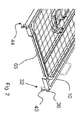
- the second attachment means 34 comprises a plurality of cross pins 38.
- the mattress frame 65 comprises a head section, a seat section, and at least one leg section connected to each other in an articulated manner, wherein the head section and the at least one leg section are operated by a respective actuator 16.
- the hook means comprises an upper hook 36 mating with a first cross pin and a lower hook 40 mating with a second cross pin.
- the lever 44 is pivotally arranged adjacent the lower hook such that when the lower hook engages the second cross pin, the lever is moved by the gravitational force so that the second hook is prevented from leaving the second cross pin.
- the lever is manually moved upwards, thereby freeing the lower hook from the second cross pin.
- the cross pins 38 are arranged vertically over each for providing flexibility in adjusting the bed depending on the length of the patient and/or caregiver.
- the mattress frame 65 is arranged with a number of articulated sections for enabling different positions of a patient, such as upraised back, lifting of legs, knee-bending, etc. These sections are operated by the actuators 16.
- the seat section is resting on two first transversal rails, the head section is pivoted arranged to one first transversal rail and the leg section is pivoted arranged to another first transversal rail.
- the actuators 16 could be electrically driven and capable of performing linear movement of a piston rod, which in turn acts on a section to pivot the first transversal rails around an articulation point, to which the head section and the at least one leg section are connected to.
- FIG. 5 shows the further versatility and flexibility of the beds according to the present invention.
- mattress extension frame 60 that is used for extending the length of the bed.
- one end of said second longitudinal rails 62 is arranged with the same type of hook means and locking means as the first longitudinal rails 10.
- the other end of the second longitudinal rails 62 is arranged with the same type of second attachment means 34 as the transversal frames 20.
- the two second longitudinal rails 62 are connected by second transversal rails 63,
- one transversal end of the mattress extension frame is connected to one transversal frame by engaging the its hook means with the cross pins of the transversal frame, whereby the lever locks the parts.
- the cross pins of the other transversal end of the mattress extension frame is then connected to hook means of the first longitudinal rails 10, whereby the lever locks the parts
- the telescopic mattress side rails 18 could still be used.
- mattresses of different thickness are frequently used, such as for example air-mattresses that can be quite thick.
- the telescopic mattress side rails can be attached at different heights in relation to the plane surface extension. At least one telescopic mattress side rail may be used for protecting the mattress from displacing transversally in relation to the bed, and at least one additional telescopic mattress side rail may be used for protecting a patient against falling off the bed.
- the telescopic mattress side rails comprise third attachment means 64 that releasebly interfaces with the fourth attachment means 66 of the transversal frames.
- the third attachment means 64 is in turn attached to two tubes 68. These tubes fit into outer tubes 70, extending along the length of the telescopic mattress side rails.
- the tubes 68 are prevented of being released from the outer tubes 70 by an attachment piece 72 connected to the third attachment means 64, and that interfaces with a pin 74 positioned on the inner surface of the telescopic mattress side rails.
- Figure 7 further shows the flexibility of the bed according to the present invention.
- the figures show another type of telescopic mattress side rails 19 having attachment brackets 76 designed to be releasably attached to the first longitudinal rails 10.
- brackets 76 On the brackets 76, posts 78 are attached and then horizontal support tubes 80 are arranged between the posts, forming the protection for the mattress from displacing transversally in relation to the bed, and for protecting a patient against falling off the bed.
- These tubes 80 fit into outer tubes, extending along the length of the side rails, in a telescopic manner.
- the floor rail 22 could be arranged with hooks or hangers for holding a transport stand or the mattress extension frame 60 of the bed when the stand or the mattress extension frame 60 is not in use. Thereby the personnel always knows where they are, which otherwise are very easy to misplace.
Abstract
Description
- The present invention relates to a bed and in particular a bed to be used for patients and the like persons that need to be nursed at home or at nursing homes.
- Beds specially designed for the demands of nursing at home or at nursing homes, need to have a number of special functions. These include e.g. mobility such that the beds are arranged with wheels, posts attached to the bed frame to be used as lifting aids, articulated parts of the bed, connection and disconnection means for storing and transporting of the bed, i.e. versatility such that the bed may be used for patients requiring different types of aid.
- Regarding connecting and disconnecting components of a bed, document
US 7,007,321 describes a connection system for side rails of a bed frame comprising a hooking element cooperating with pins wherein a hook plate is forced downwards by manually pivoting a lever arm such that the pins are locked in slots of the hook plate. - Another example of attaching components to a bed frame is shown in
JP 10258093 - Another feature that many beds of this type have is latch mechanisms for articulated parts of the bed to position them in different angular positions.
US 5,706,536 discloses a latch mechanism of a knee section of a bed where the latch mechanism comprises a ratchet plate and clevis pin engaging the notches of the ratchet. In order to lower the knee section, the clevis pin is moved past the last notch and towards a cam surface, whereby an escapement plate is urged so that it covers the notches. - The document
US 5,513,406 discloses a hospital bed capable of being transformed into various functional beds/chairs for handling various stages of treatment and/or care of a patient. It is thus possible to connect different equipment to the bed depending on situation such as transport module group, patient critical care/step group and patient ambulatory/rehabilitation group. Each group comprises different modules such as for example a care cart module for the transport group, a weigh scale module for the patient critical care group and a exerciser unit for the patient rehabilitation group. - However, none of the disclosed beds are as such truly versatile or flexible regarding modifications and alterations depending on patient conditions and size.
- The aim of the present invention is to remedy the drawbacks of the state of the art and to provide a versatile care bed system for nursing patients at home.
- This aim is obtained by the features of the independent patent claims. Preferable embodiments of the present invention are found in the dependent patent claims.
- According to a main aspect of the invention it is characterised by a bed having a length and a width and comprising two first longitudinal rails comprising on their ends first attachment means; telescopic mattress side rails comprising on their ends third attachment means; two transversal frames adapted to be resting on a plane surface, comprising second attachment means that releasably interfaces the first attachment means, and fourth attachment means that releasably interfaces the third attachment means, wherein said second attachment means and respective said fourth attachment means are arranged vertically over each other for permitting the positioning of said two first longitudinal rails and respective said telescopic mattress side rails at different heights in relation to said plane surface; first transversal rails being transversally connected to said longitudinal rails; a mattress frame resting on said first transversal rails; a mattress extension frame comprising two second longitudinal rails and second transversal rails, wherein each second longitudinal rails comprises first attachment means that releasably interfaces the second attachment means of one of the transversal frames, and second attachment means that releasably interfaces the first attachment means of each first longitudinal rail for extending the length of the bed.
- The present invention has a number of advantages in comparison with the known devices in this technical area. The bed according to the present invention provides a great versatility and flexibility in that it is very easy to extend the length of the bed with the mattress extension frame, which is provided with second longitudinal rails and second transversal rails, and with the same type of attachment means as the first longitudinal rails. Since the attachment means preferably have locking means that act by gravity, it is assured that the bed frame is securely locked to the end piece without having to perform further actions.
- The flexibility is further ensured in that there is a plurality of attachment positions on the transversal frames in the height direction It is thus possible to adjust the height of the bed rest depending on the length of the patient and/or caregiver.
- Further, because of the possibility of extending the length of the bed, telescopic mattress side rails are positioned between the transversal frames.
- These and other aspects of and advantages with the present invention will become apparent from the following detailed description and the accompanying drawings.
- In the detailed description, reference will be made to the accompanying drawings, of which
-
Fig. 1 shows a side view of an embodiment of a bed according to the present invention, -
Fig. 2 shows a perspective view of the bed ofFig. 1 , without a transversal frame, -
Fig. 3 shows a perspective view of the bed ofFig. 1 , with the transversal frame, -
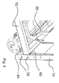
Fig. 4 shows a detailed view of the connection of one transversal frame with a first longitudinal rail, -
Fig. 5 shows a perspective view of a mattress extension frame, -
Fig. 6 show a detailed view in cross-section of the telescopic mattress side rail to be used with the present bed, -
Fig. 7 show an extendable side guard, - The embodiment of the present invention shown in the drawings is a bed having a length and a width. Said bed comprises two first
longitudinal rails 10 comprising on their ends first attachment means 32; telescopicmattress side rails 18 comprising on their ends third attachment means 64; twotransversal frames 20 adapted to be resting on a plane surface, comprising second attachment means 34 that releasably interfaces the first attachment means 32, and fourth attachment means 66 that releasably interfaces the third attachment means 64, wherein said second attachment means 34 and respective said fourth attachment means 66 are arranged vertically over each other for permitting the positioning of said two first longitudinal rails and respective said telescopic mattress side rails at different heights in relation to said plane surface; first transversal rails being transversally connected to said longitudinal rails; amattress frame 65 resting on said first transversal rails (not shown); amattress extension frame 60 comprising two secondlongitudinal rails 62 and secondtransversal rails 63, wherein each second longitudinal rails comprises first attachment means 32 that releasably interfaces the second attachment means of one of the transversal frames, and second attachment means 34 that releasably interfaces the first attachment means 32 of each first longitudinal rail for extending the length of the bed. - As shown in
Fig 3 , eachtransversal frame 20 comprises afloor rail 22 and a U-shaped frame having ahorizontal part 24 and twovertical parts 14 and at least onevertical rail 28 connecting saidfloor rail 22 and said U-shaped frame. Thefloor frame 22 comprises a pair ofcaster 26 for rolling the bed on the plane surface and the at least onevertical rail 28 is telescopically arranged. Also anactuator 30 is connected to saidfloor rail 22 and to said horizontal part of the U-shapedframe 24. The at least one telescopicvertical rail 28 comprises acting guide tubes and in order to reduce the friction between the inner and the outer guide tubes, bushings are arranged, making the movement smooth and silent when the bed is raised or lowered by theactuators 30. - A shown in
Fig.2 , the first attachment means 32 comprises hook means and locking means for locking said first attachment means to said second attachment means wherein said locking means comprises alever 44 arranged such that it is moved into a locking position by gravity. The second attachment means 34 comprises a plurality ofcross pins 38. - The
mattress frame 65 comprises a head section, a seat section, and at least one leg section connected to each other in an articulated manner, wherein the head section and the at least one leg section are operated by arespective actuator 16. - The hook means comprises an
upper hook 36 mating with a first cross pin and alower hook 40 mating with a second cross pin. Thelever 44 is pivotally arranged adjacent the lower hook such that when the lower hook engages the second cross pin, the lever is moved by the gravitational force so that the second hook is prevented from leaving the second cross pin. When the first attachment means are to be disconnected from the second attachment means, the lever is manually moved upwards, thereby freeing the lower hook from the second cross pin. As seen fromFig. 4 , thecross pins 38 are arranged vertically over each for providing flexibility in adjusting the bed depending on the length of the patient and/or caregiver. - As mentioned the
mattress frame 65 is arranged with a number of articulated sections for enabling different positions of a patient, such as upraised back, lifting of legs, knee-bending, etc. These sections are operated by theactuators 16. The seat section is resting on two first transversal rails, the head section is pivoted arranged to one first transversal rail and the leg section is pivoted arranged to another first transversal rail. Theactuators 16 could be electrically driven and capable of performing linear movement of a piston rod, which in turn acts on a section to pivot the first transversal rails around an articulation point, to which the head section and the at least one leg section are connected to. -
Figure 5 shows the further versatility and flexibility of the beds according to the present invention. There it is shownmattress extension frame 60 that is used for extending the length of the bed. As seen, one end of said secondlongitudinal rails 62 is arranged with the same type of hook means and locking means as the firstlongitudinal rails 10. The other end of the secondlongitudinal rails 62 is arranged with the same type of second attachment means 34 as thetransversal frames 20. The two secondlongitudinal rails 62 are connected by secondtransversal rails 63, Thus if a bed needs to be extended due to a long patient, one transversal end of the mattress extension frame is connected to one transversal frame by engaging the its hook means with the cross pins of the transversal frame, whereby the lever locks the parts. The cross pins of the other transversal end of the mattress extension frame is then connected to hook means of the firstlongitudinal rails 10, whereby the lever locks the parts - When the bed is extended it is an advantage that the telescopic
mattress side rails 18 could still be used. Moreover, with this type of bed, mattresses of different thickness are frequently used, such as for example air-mattresses that can be quite thick. In order to have a proper protection from the side rails, the telescopic mattress side rails can be attached at different heights in relation to the plane surface extension. At least one telescopic mattress side rail may be used for protecting the mattress from displacing transversally in relation to the bed, and at least one additional telescopic mattress side rail may be used for protecting a patient against falling off the bed. - As seen in
Fig. 6 , the telescopic mattress side rails comprise third attachment means 64 that releasebly interfaces with the fourth attachment means 66 of the transversal frames. The third attachment means 64 is in turn attached to twotubes 68. These tubes fit intoouter tubes 70, extending along the length of the telescopic mattress side rails. Thetubes 68 are prevented of being released from theouter tubes 70 by anattachment piece 72 connected to the third attachment means 64, and that interfaces with apin 74 positioned on the inner surface of the telescopic mattress side rails. -
Figure 7 further shows the flexibility of the bed according to the present invention. The figures show another type of telescopic mattress side rails 19 havingattachment brackets 76 designed to be releasably attached to the first longitudinal rails 10. On thebrackets 76, posts 78 are attached and thenhorizontal support tubes 80 are arranged between the posts, forming the protection for the mattress from displacing transversally in relation to the bed, and for protecting a patient against falling off the bed. Thesetubes 80 fit into outer tubes, extending along the length of the side rails, in a telescopic manner. - The
floor rail 22 could be arranged with hooks or hangers for holding a transport stand or themattress extension frame 60 of the bed when the stand or themattress extension frame 60 is not in use. Thereby the personnel always knows where they are, which otherwise are very easy to misplace. - It is to be understood that the embodiments of the invention described above and shown in the drawings are to be regarded only as non-limiting examples of the invention and that it may be modified in many ways within the scope of the patent claims.
Claims (9)
- Bed having a length and a width and comprising:- two first longitudinal rails (10) comprising on their ends first attachment means (32);- telescopic mattress side rails (18) comprising on their ends third attachment means (64);- two transversal frames adapted to be resting on a plane surface, comprising second attachment means (34) that releasably interfaces the first attachment means (32), and fourth attachment means (66) that releasably interfaces the third attachment means (64), wherein said second attachment means (34) and respective said fourth attachment means (66) are arranged vertically over each other for permitting the positioning of said two first longitudinal rails and respective said telescopic mattress side rails at different heights in relation to said plane surface;- first transversal rails being transversally connected to said longitudinal rails;- a mattress frame resting on said first transversal rails;- a mattress extension frame (60) comprising two second longitudinal rails (62) and second transversal rails, wherein each second longitudinal rails comprises first attachment means (32) that releasably interfaces the second attachment means of one of the transversal frames, and second attachment means (34) that releasably interfaces the first attachment means (32) of each first longitudinal rail for extending the length of the bed.
- Bed according to claim 1, wherein said first attachment means (32) comprises hook means (36, 40) and locking means for locking said first attachment means to said second attachment means.
- Bed according to claim 2, wherein said locking means comprises a lever (44) arranged such that it is moved into a locking position by gravity.
- Bed according to any one of the preceding claims 1-3, wherein said second attachment means (34) comprises a plurality of cross pins.
- Bed according to any one of the preceding claims 1-4, wherein said telescopic mattress side rails comprise tubular members telescopically arranged inside each other.
- Bed according to any one of the preceding claims 1-5, wherein each transversal frame comprises a floor rail (22) and a U-shaped frame (24) having a horizontal part and two vertical parts and at least one vertical rail (28) connecting said floor rail (22) and said U-shaped frame (24).
- Bed according to claim 6, wherein said floor frame comprises a pair of caster (26).
- Bed according to any one of the preceding claims 6-7, wherein said at least one vertical rail (28) is telescopically arranged and wherein an actuator (20) is connected to said floor rail (22) and to said horizontal part of the U-shaped frame (24).
- Bed according to any one of the preceding claims 1-8, wherein the mattress frame comprising a head section (10a), a seat section, and at least one leg section (10b, 10c) connected to each other in an articulated manner, wherein the head section and the at least one leg section are operated by a respective actuator (16).
Applications Claiming Priority (1)
| Application Number | Priority Date | Filing Date | Title |
|---|---|---|---|
| SE0800471 | 2008-02-28 |
Publications (2)
| Publication Number | Publication Date |
|---|---|
| EP2095744A1 true EP2095744A1 (en) | 2009-09-02 |
| EP2095744B1 EP2095744B1 (en) | 2010-03-17 |
Family
ID=40478387
Family Applications (1)
| Application Number | Title | Priority Date | Filing Date |
|---|---|---|---|
| EP09152505A Active EP2095744B1 (en) | 2008-02-28 | 2009-02-11 | Bed |
Country Status (3)
| Country | Link |
|---|---|
| EP (1) | EP2095744B1 (en) |
| AT (1) | ATE460861T1 (en) |
| DE (1) | DE602009000010D1 (en) |
Citations (10)
| Publication number | Priority date | Publication date | Assignee | Title |
|---|---|---|---|---|
| US1514447A (en) * | 1923-05-29 | 1924-11-04 | Bernard H Edwards | Bed extension |
| US1546065A (en) * | 1924-04-05 | 1925-07-14 | Greenpoint Metallic Bed Co Inc | Bedstead |
| US5513406A (en) | 1994-04-21 | 1996-05-07 | Hill-Rom Company, Inc. | Modular hospital bed and method of patient handling |
| US5706536A (en) | 1995-12-14 | 1998-01-13 | Joerns Healthcare Inc. | Latch mechanism for articulated beds and the like |
| JPH10258093A (en) | 1997-03-17 | 1998-09-29 | Tachi S Co Ltd | Board mounting structure of medical bed |
| US20020116764A1 (en) * | 2001-02-26 | 2002-08-29 | Plummer Stephen B. | Bed with adjustable positions |
| WO2005051127A2 (en) * | 2003-11-21 | 2005-06-09 | Finger Lakes Intellectual Property, Llc | Side rail end connection system for bed frame |
| EP1541108A1 (en) * | 2002-08-29 | 2005-06-15 | Sanyo Electric Co., Ltd. | Movable bed |
| US20050278858A1 (en) * | 2004-05-14 | 2005-12-22 | Polevoy Richard S | Bed frame with extended bumper assembly |
| DE102005045423A1 (en) * | 2005-09-23 | 2007-04-05 | Joh. Stiegelmeyer Gmbh & Co. Kg | Hospital bed adjustable in length, comprises covers for lateral parts with overlapping segments |
-
2009
- 2009-02-11 EP EP09152505A patent/EP2095744B1/en active Active
- 2009-02-11 DE DE602009000010T patent/DE602009000010D1/en active Active
- 2009-02-11 AT AT09152505T patent/ATE460861T1/en active
Patent Citations (11)
| Publication number | Priority date | Publication date | Assignee | Title |
|---|---|---|---|---|
| US1514447A (en) * | 1923-05-29 | 1924-11-04 | Bernard H Edwards | Bed extension |
| US1546065A (en) * | 1924-04-05 | 1925-07-14 | Greenpoint Metallic Bed Co Inc | Bedstead |
| US5513406A (en) | 1994-04-21 | 1996-05-07 | Hill-Rom Company, Inc. | Modular hospital bed and method of patient handling |
| US5706536A (en) | 1995-12-14 | 1998-01-13 | Joerns Healthcare Inc. | Latch mechanism for articulated beds and the like |
| JPH10258093A (en) | 1997-03-17 | 1998-09-29 | Tachi S Co Ltd | Board mounting structure of medical bed |
| US20020116764A1 (en) * | 2001-02-26 | 2002-08-29 | Plummer Stephen B. | Bed with adjustable positions |
| EP1541108A1 (en) * | 2002-08-29 | 2005-06-15 | Sanyo Electric Co., Ltd. | Movable bed |
| WO2005051127A2 (en) * | 2003-11-21 | 2005-06-09 | Finger Lakes Intellectual Property, Llc | Side rail end connection system for bed frame |
| US7007321B2 (en) | 2003-11-21 | 2006-03-07 | Finger Lakes Intellectual Property Llc | Side rail end connection system for bed frame |
| US20050278858A1 (en) * | 2004-05-14 | 2005-12-22 | Polevoy Richard S | Bed frame with extended bumper assembly |
| DE102005045423A1 (en) * | 2005-09-23 | 2007-04-05 | Joh. Stiegelmeyer Gmbh & Co. Kg | Hospital bed adjustable in length, comprises covers for lateral parts with overlapping segments |
Also Published As
| Publication number | Publication date |
|---|---|
| ATE460861T1 (en) | 2010-04-15 |
| EP2095744B1 (en) | 2010-03-17 |
| DE602009000010D1 (en) | 2010-04-29 |
Similar Documents
| Publication | Publication Date | Title |
|---|---|---|
| US10588801B1 (en) | Bed with pivotable bed surface | |
| EP1948107B1 (en) | Patient transfer system with operating table conversion platform | |
| US8407831B2 (en) | Patient positioning apparatus | |
| US20080301873A1 (en) | Patient Positioning apparatus | |
| WO2007016559A2 (en) | Patient transfer system | |
| WO2007067874A2 (en) | Patient single surface system | |
| US8863331B2 (en) | Securing mechanism for a height adjustable emergency cot | |
| CN109718023A (en) | It is multifunction nursing bed | |
| US9408766B2 (en) | Patient transport vehicle | |
| EP2095744B1 (en) | Bed | |
| WO1992008433A1 (en) | Transfer and nursing system for a patient | |
| US11389355B2 (en) | Guard rail for a bed, guide rack for a guard rail and a bed with such guard rail | |
| CA2646024C (en) | Patient position apparatus | |
| CZ2019546A3 (en) | Extension of the bed area | |
| US20090013474A1 (en) | Offset patient trapeze system | |
| CA2626491C (en) | Patient transfer system with operating table conversion platform | |
| KR200417392Y1 (en) | Bed for patient having combination-type mattress | |
| EP1552772A1 (en) | Side Rail, hospital bed including the same, method of operating associated thereto and kit for assembling the side rail | |
| WO2021148864A1 (en) | Smooth lateral patient transfer apparatus | |
| CZ33248U1 (en) | Extension mechanism of the upper frame of the bed surface |
Legal Events
| Date | Code | Title | Description |
|---|---|---|---|
| PUAI | Public reference made under article 153(3) epc to a published international application that has entered the european phase |
Free format text: ORIGINAL CODE: 0009012 |
|
| AK | Designated contracting states |
Kind code of ref document: A1 Designated state(s): AT BE BG CH CY CZ DE DK EE ES FI FR GB GR HR HU IE IS IT LI LT LU LV MC MK MT NL NO PL PT RO SE SI SK TR |
|
| AX | Request for extension of the european patent |
Extension state: AL BA RS |
|
| GRAP | Despatch of communication of intention to grant a patent |
Free format text: ORIGINAL CODE: EPIDOSNIGR1 |
|
| 17P | Request for examination filed |
Effective date: 20090922 |
|
| GRAS | Grant fee paid |
Free format text: ORIGINAL CODE: EPIDOSNIGR3 |
|
| GRAA | (expected) grant |
Free format text: ORIGINAL CODE: 0009210 |
|
| AK | Designated contracting states |
Kind code of ref document: B1 Designated state(s): AT BE BG CH CY CZ DE DK EE ES FI FR GB GR HR HU IE IS IT LI LT LU LV MC MK MT NL NO PL PT RO SE SI SK TR |
|
| REG | Reference to a national code |
Ref country code: GB Ref legal event code: FG4D |
|
| REG | Reference to a national code |
Ref country code: CH Ref legal event code: EP |
|
| REG | Reference to a national code |
Ref country code: IE Ref legal event code: FG4D |
|
| REF | Corresponds to: |
Ref document number: 602009000010 Country of ref document: DE Date of ref document: 20100429 Kind code of ref document: P |
|
| AKX | Designation fees paid |
Designated state(s): AT BE BG CH CY CZ DE DK EE ES FI FR GB GR HR HU IE IS IT LI LT LU LV MC MK MT NL NO PL PT RO SE SI SK TR |
|
| REG | Reference to a national code |
Ref country code: SE Ref legal event code: TRGR |
|
| REG | Reference to a national code |
Ref country code: NL Ref legal event code: VDEP Effective date: 20100317 |
|
| PG25 | Lapsed in a contracting state [announced via postgrant information from national office to epo] |
Ref country code: NO Free format text: LAPSE BECAUSE OF FAILURE TO SUBMIT A TRANSLATION OF THE DESCRIPTION OR TO PAY THE FEE WITHIN THE PRESCRIBED TIME-LIMIT Effective date: 20100617 Ref country code: LT Free format text: LAPSE BECAUSE OF FAILURE TO SUBMIT A TRANSLATION OF THE DESCRIPTION OR TO PAY THE FEE WITHIN THE PRESCRIBED TIME-LIMIT Effective date: 20100317 Ref country code: HR Free format text: LAPSE BECAUSE OF FAILURE TO SUBMIT A TRANSLATION OF THE DESCRIPTION OR TO PAY THE FEE WITHIN THE PRESCRIBED TIME-LIMIT Effective date: 20100317 |
|
| LTIE | Lt: invalidation of european patent or patent extension |
Effective date: 20100317 |
|
| PG25 | Lapsed in a contracting state [announced via postgrant information from national office to epo] |
Ref country code: PL Free format text: LAPSE BECAUSE OF FAILURE TO SUBMIT A TRANSLATION OF THE DESCRIPTION OR TO PAY THE FEE WITHIN THE PRESCRIBED TIME-LIMIT Effective date: 20100317 Ref country code: LV Free format text: LAPSE BECAUSE OF FAILURE TO SUBMIT A TRANSLATION OF THE DESCRIPTION OR TO PAY THE FEE WITHIN THE PRESCRIBED TIME-LIMIT Effective date: 20100317 Ref country code: FI Free format text: LAPSE BECAUSE OF FAILURE TO SUBMIT A TRANSLATION OF THE DESCRIPTION OR TO PAY THE FEE WITHIN THE PRESCRIBED TIME-LIMIT Effective date: 20100317 Ref country code: SI Free format text: LAPSE BECAUSE OF FAILURE TO SUBMIT A TRANSLATION OF THE DESCRIPTION OR TO PAY THE FEE WITHIN THE PRESCRIBED TIME-LIMIT Effective date: 20100317 |
|
| PG25 | Lapsed in a contracting state [announced via postgrant information from national office to epo] |
Ref country code: RO Free format text: LAPSE BECAUSE OF FAILURE TO SUBMIT A TRANSLATION OF THE DESCRIPTION OR TO PAY THE FEE WITHIN THE PRESCRIBED TIME-LIMIT Effective date: 20100317 Ref country code: NL Free format text: LAPSE BECAUSE OF FAILURE TO SUBMIT A TRANSLATION OF THE DESCRIPTION OR TO PAY THE FEE WITHIN THE PRESCRIBED TIME-LIMIT Effective date: 20100317 Ref country code: GR Free format text: LAPSE BECAUSE OF FAILURE TO SUBMIT A TRANSLATION OF THE DESCRIPTION OR TO PAY THE FEE WITHIN THE PRESCRIBED TIME-LIMIT Effective date: 20100618 Ref country code: ES Free format text: LAPSE BECAUSE OF FAILURE TO SUBMIT A TRANSLATION OF THE DESCRIPTION OR TO PAY THE FEE WITHIN THE PRESCRIBED TIME-LIMIT Effective date: 20100628 Ref country code: EE Free format text: LAPSE BECAUSE OF FAILURE TO SUBMIT A TRANSLATION OF THE DESCRIPTION OR TO PAY THE FEE WITHIN THE PRESCRIBED TIME-LIMIT Effective date: 20100317 Ref country code: CY Free format text: LAPSE BECAUSE OF FAILURE TO SUBMIT A TRANSLATION OF THE DESCRIPTION OR TO PAY THE FEE WITHIN THE PRESCRIBED TIME-LIMIT Effective date: 20100317 |
|
| PG25 | Lapsed in a contracting state [announced via postgrant information from national office to epo] |
Ref country code: SK Free format text: LAPSE BECAUSE OF FAILURE TO SUBMIT A TRANSLATION OF THE DESCRIPTION OR TO PAY THE FEE WITHIN THE PRESCRIBED TIME-LIMIT Effective date: 20100317 Ref country code: BG Free format text: LAPSE BECAUSE OF FAILURE TO SUBMIT A TRANSLATION OF THE DESCRIPTION OR TO PAY THE FEE WITHIN THE PRESCRIBED TIME-LIMIT Effective date: 20100617 Ref country code: CZ Free format text: LAPSE BECAUSE OF FAILURE TO SUBMIT A TRANSLATION OF THE DESCRIPTION OR TO PAY THE FEE WITHIN THE PRESCRIBED TIME-LIMIT Effective date: 20100317 Ref country code: IS Free format text: LAPSE BECAUSE OF FAILURE TO SUBMIT A TRANSLATION OF THE DESCRIPTION OR TO PAY THE FEE WITHIN THE PRESCRIBED TIME-LIMIT Effective date: 20100717 |
|
| PLBE | No opposition filed within time limit |
Free format text: ORIGINAL CODE: 0009261 |
|
| STAA | Information on the status of an ep patent application or granted ep patent |
Free format text: STATUS: NO OPPOSITION FILED WITHIN TIME LIMIT |
|
| PG25 | Lapsed in a contracting state [announced via postgrant information from national office to epo] |
Ref country code: DK Free format text: LAPSE BECAUSE OF FAILURE TO SUBMIT A TRANSLATION OF THE DESCRIPTION OR TO PAY THE FEE WITHIN THE PRESCRIBED TIME-LIMIT Effective date: 20100317 |
|
| 26N | No opposition filed |
Effective date: 20101220 |
|
| PG25 | Lapsed in a contracting state [announced via postgrant information from national office to epo] |
Ref country code: IT Free format text: LAPSE BECAUSE OF FAILURE TO SUBMIT A TRANSLATION OF THE DESCRIPTION OR TO PAY THE FEE WITHIN THE PRESCRIBED TIME-LIMIT Effective date: 20100317 |
|
| PG25 | Lapsed in a contracting state [announced via postgrant information from national office to epo] |
Ref country code: MC Free format text: LAPSE BECAUSE OF NON-PAYMENT OF DUE FEES Effective date: 20110228 |
|
| PG25 | Lapsed in a contracting state [announced via postgrant information from national office to epo] |
Ref country code: MT Free format text: LAPSE BECAUSE OF FAILURE TO SUBMIT A TRANSLATION OF THE DESCRIPTION OR TO PAY THE FEE WITHIN THE PRESCRIBED TIME-LIMIT Effective date: 20100317 |
|
| PGFP | Annual fee paid to national office [announced via postgrant information from national office to epo] |
Ref country code: LU Payment date: 20130213 Year of fee payment: 5 |
|
| PGFP | Annual fee paid to national office [announced via postgrant information from national office to epo] |
Ref country code: SE Payment date: 20130212 Year of fee payment: 5 Ref country code: IE Payment date: 20130212 Year of fee payment: 5 Ref country code: CH Payment date: 20130212 Year of fee payment: 5 Ref country code: DE Payment date: 20130206 Year of fee payment: 5 Ref country code: GB Payment date: 20130207 Year of fee payment: 5 Ref country code: FR Payment date: 20130301 Year of fee payment: 5 |
|
| PGFP | Annual fee paid to national office [announced via postgrant information from national office to epo] |
Ref country code: BE Payment date: 20130212 Year of fee payment: 5 |
|
| PG25 | Lapsed in a contracting state [announced via postgrant information from national office to epo] |
Ref country code: PT Free format text: LAPSE BECAUSE OF NON-PAYMENT OF DUE FEES Effective date: 20100317 |
|
| PG25 | Lapsed in a contracting state [announced via postgrant information from national office to epo] |
Ref country code: TR Free format text: LAPSE BECAUSE OF FAILURE TO SUBMIT A TRANSLATION OF THE DESCRIPTION OR TO PAY THE FEE WITHIN THE PRESCRIBED TIME-LIMIT Effective date: 20100317 |
|
| PG25 | Lapsed in a contracting state [announced via postgrant information from national office to epo] |
Ref country code: HU Free format text: LAPSE BECAUSE OF FAILURE TO SUBMIT A TRANSLATION OF THE DESCRIPTION OR TO PAY THE FEE WITHIN THE PRESCRIBED TIME-LIMIT Effective date: 20100317 |
|
| BERE | Be: lapsed |
Owner name: SHL GROUP A.B. Effective date: 20140228 |
|
| REG | Reference to a national code |
Ref country code: DE Ref legal event code: R119 Ref document number: 602009000010 Country of ref document: DE |
|
| PG25 | Lapsed in a contracting state [announced via postgrant information from national office to epo] |
Ref country code: LU Free format text: LAPSE BECAUSE OF NON-PAYMENT OF DUE FEES Effective date: 20140211 |
|
| REG | Reference to a national code |
Ref country code: SE Ref legal event code: EUG Ref country code: CH Ref legal event code: PL |
|
| GBPC | Gb: european patent ceased through non-payment of renewal fee |
Effective date: 20140211 |
|
| PG25 | Lapsed in a contracting state [announced via postgrant information from national office to epo] |
Ref country code: LI Free format text: LAPSE BECAUSE OF NON-PAYMENT OF DUE FEES Effective date: 20140228 Ref country code: CH Free format text: LAPSE BECAUSE OF NON-PAYMENT OF DUE FEES Effective date: 20140228 |
|
| REG | Reference to a national code |
Ref country code: FR Ref legal event code: ST Effective date: 20141031 |
|
| REG | Reference to a national code |
Ref country code: DE Ref legal event code: R119 Ref document number: 602009000010 Country of ref document: DE Effective date: 20140902 |
|
| PG25 | Lapsed in a contracting state [announced via postgrant information from national office to epo] |
Ref country code: SE Free format text: LAPSE BECAUSE OF NON-PAYMENT OF DUE FEES Effective date: 20140212 |
|
| REG | Reference to a national code |
Ref country code: IE Ref legal event code: MM4A |
|
| PG25 | Lapsed in a contracting state [announced via postgrant information from national office to epo] |
Ref country code: BE Free format text: LAPSE BECAUSE OF NON-PAYMENT OF DUE FEES Effective date: 20140228 Ref country code: FR Free format text: LAPSE BECAUSE OF NON-PAYMENT OF DUE FEES Effective date: 20140228 Ref country code: GB Free format text: LAPSE BECAUSE OF NON-PAYMENT OF DUE FEES Effective date: 20140211 Ref country code: DE Free format text: LAPSE BECAUSE OF NON-PAYMENT OF DUE FEES Effective date: 20140902 Ref country code: IE Free format text: LAPSE BECAUSE OF NON-PAYMENT OF DUE FEES Effective date: 20140211 |
|
| REG | Reference to a national code |
Ref country code: AT Ref legal event code: MM01 Ref document number: 460861 Country of ref document: AT Kind code of ref document: T Effective date: 20140211 |
|
| PG25 | Lapsed in a contracting state [announced via postgrant information from national office to epo] |
Ref country code: AT Free format text: LAPSE BECAUSE OF NON-PAYMENT OF DUE FEES Effective date: 20140211 |