EP2096446A2 - Automatic analyzer - Google Patents
Automatic analyzer Download PDFInfo
- Publication number
- EP2096446A2 EP2096446A2 EP09150640A EP09150640A EP2096446A2 EP 2096446 A2 EP2096446 A2 EP 2096446A2 EP 09150640 A EP09150640 A EP 09150640A EP 09150640 A EP09150640 A EP 09150640A EP 2096446 A2 EP2096446 A2 EP 2096446A2
- Authority
- EP
- European Patent Office
- Prior art keywords
- sample
- diluted sample
- analysis
- inspection
- diluted
- Prior art date
- Legal status (The legal status is an assumption and is not a legal conclusion. Google has not performed a legal analysis and makes no representation as to the accuracy of the status listed.)
- Granted
Links
Images

Classifications
-
- G—PHYSICS
- G01—MEASURING; TESTING
- G01N—INVESTIGATING OR ANALYSING MATERIALS BY DETERMINING THEIR CHEMICAL OR PHYSICAL PROPERTIES
- G01N35/00—Automatic analysis not limited to methods or materials provided for in any single one of groups G01N1/00 - G01N33/00; Handling materials therefor
- G01N35/00584—Control arrangements for automatic analysers
- G01N35/00594—Quality control, including calibration or testing of components of the analyser
- G01N35/00613—Quality control
- G01N35/00663—Quality control of consumables
-
- G—PHYSICS
- G01—MEASURING; TESTING
- G01N—INVESTIGATING OR ANALYSING MATERIALS BY DETERMINING THEIR CHEMICAL OR PHYSICAL PROPERTIES
- G01N35/00—Automatic analysis not limited to methods or materials provided for in any single one of groups G01N1/00 - G01N33/00; Handling materials therefor
- G01N35/00584—Control arrangements for automatic analysers
- G01N35/00722—Communications; Identification
- G01N2035/00891—Displaying information to the operator
- G01N2035/0091—GUI [graphical user interfaces]
-
- G—PHYSICS
- G01—MEASURING; TESTING
- G01N—INVESTIGATING OR ANALYSING MATERIALS BY DETERMINING THEIR CHEMICAL OR PHYSICAL PROPERTIES
- G01N35/00—Automatic analysis not limited to methods or materials provided for in any single one of groups G01N1/00 - G01N33/00; Handling materials therefor
- G01N35/10—Devices for transferring samples or any liquids to, in, or from, the analysis apparatus, e.g. suction devices, injection devices
- G01N2035/1027—General features of the devices
- G01N2035/1032—Dilution or aliquotting
-
- G—PHYSICS
- G01—MEASURING; TESTING
- G01N—INVESTIGATING OR ANALYSING MATERIALS BY DETERMINING THEIR CHEMICAL OR PHYSICAL PROPERTIES
- G01N35/00—Automatic analysis not limited to methods or materials provided for in any single one of groups G01N1/00 - G01N33/00; Handling materials therefor
- G01N35/00584—Control arrangements for automatic analysers
Definitions
- the present invention relates to automatic analyzers for performing qualitative/quantitative analysis of samples such as blood and urine.
- the invention more particularly relates to an automatic analyzer including: a parent sample vessel holding unit for holding a parent sample; a diluted sample vessel holding unit in which a diluted sample vessel is placed, the diluted sample vessel holding a diluted sample made by diluting, with diluent, a sample pipetted from the parent sample; and a reaction vessel in which the analysis, inspection, and measurement of the diluted sample are performed.
- JP-A-8-194004 discloses an automatic analyzer that uses a method in which a parent sample is diluted with diluent to ensure the fluid volume required for measurement items.
- the above-described automatic analyzer stores, in a diluted sample vessel, a diluted sample that remains after analysis and inspection to thereby meet a request for reinspection.
- the diluted sample may dry and adhere to a diluted sample vessel, which leads to a difficulty in washing and leads to a deterioration of the diluted sample itself. Consequently the diluted sample will become unsuitable for the qualitative/quantitative analysis and inspection.
- An object of the present invention is to provide an automatic analyzer that hardly creates inconveniences including a case where a diluted sample becomes unsuitable for the qualitative/quantitative analysis and inspection because of the adhesion of the diluted sample due to drying, and because of the deterioration of the diluted sample.
- another object of the present invention is to provide an automatic analyzer that is capable of checking, before measurement for the analysis and inspection is executed, whether or not all requested measurement items for the analysis and inspection can be completely measured, and that is capable of checking, before measurement for the analysis and inspection is executed, the time it takes before measurement of all samples is completed.
- an automatic analyzer for performing the analysis and inspection of various kinds of samples including a parent sample, a diluted sample, and a combination sample in which the diluted sample and the parent sample are used in combination, said automatic analyzer comprising:
- an automatic analyzer for performing the analysis and inspection of various kinds of samples including a parent sample, a diluted sample, and a combination sample in which the diluted sample and the parent sample are used in combination, said automatic analyzer comprising:
- the automatic analyzer further includes a display unit for displaying, on a screen, various kinds of information about the analysis and inspection.
- a display unit for displaying, on a screen, various kinds of information about the analysis and inspection.
- the estimated length of time it takes to complete the analysis and inspection of the whole requested diluted sample is displayed on the display unit.
- the automatic analyzer has afunction of discarding, from the diluted sample vessel, the remaining diluted sample that remains after pipetting in analysis and inspection, and holding the remaining diluted sample in the diluted sample vessel.
- the automatic analyzer therefore, can meet a request for remeasurement using the remaining diluted sample. If the elapsed time during which a diluted sample is held becomes too long, the diluted sample is discarded. This makes it possible to make full use of the diluted sample, and to prevent a failure of measurement for the reanalysis and reinspection from occurring which would result from the adhesion of a diluted sample to the diluted sample vessel due to drying and the deterioration of the diluted sample.
- the automatic analyzer is capable of, before the analysis and inspection, knowing how many times and how much the analysis and inspection can be performed on the basis of the amount of the diluted sample that has been diluted, and is capable of displaying, on the display unit, the estimated length of time it takes to complete the analysis and inspection of the whole requested diluted sample.
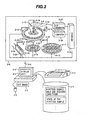
- Fig. 2 is a diagram schematically illustrating the overall configuration of an automatic analyzer based on principles.
- reference numeral 2-1 denotes an operation unit.
- the operation unit 2-1 is a computer equipped with peripheral devices.
- the peripheral devices are a keyboard 2-2 for inputting data; a mouse 2-3; a display unit for displaying data 2-4; a printer 2-5 for printing data; an interface 2-6 through which a connection to an analyzing unit is made; and a storage device 2-7 for storing hold and discard conditions of a diluted sample and a state of the diluted sample.
- Reference numeral 2-8 denotes an analyzing unit.
- the analyzing unit 2-8 is connected to the operation unit 2-1 through the interface 2-6.
- the analyzing unit 2-8 includes a reaction disk 2-9.
- a plurality of reaction vessels 2-10 are disposed along the concentric circumference of the reaction disk 2-9.
- Reference numeral 2-11 denotes a reagent disk.
- a plurality of reagent bottles 2-12 containing various kinds of reagents are disposed along the concentric circumference of the reagent disk 2-11.
- Around the reaction disk 2-9 disposed are a pipetting probe 2-13 for pipetting a diluted sample into the reaction disk 2-9; a mixer 2-14; a cleaning device 2-15; a light source 2-16; and a multiwavelength photometer 2-17.
- a reagent pipetting probe 2-18 is disposed between the reaction disk 2-9 and the reagent disk 2-11.
- a diluted sample disk 2-19 is disposed at a position adjacent to the reagent disk 2-11 in such a manner that the diluted sample disk 2-19 is associated with the circumference of the rotating diluted sample pipetting probe 2-13.
- a plurality of diluted sample vessels 2-20 each containing a diluted sample are located on the diluted sample disk 2-19.
- the reagent disk 2-11 has the plurality of reagent bottles 2-12 thereon, each of which contains a reagent used to dilute a sample and/or a reagent used to analyze and inspect a sample. Further, a rack transfer belt 2-24 is extended at a position adjacent to the diluted sample disk 2-19. A rack 2-22 moves along the rack transfer belt 2-24. A plurality of parent sample vessels 2-23 each containing a parent sample are placed in the rack 2-22.
- a parent sample pipetting probe 2-21 is disposed between the diluted sample disk 2-19 and the rack transfer belt 2-24.
- the operation of the above-described mechanism is totally controlled by the computer 2-26 through the interface 2-25.
- An operator uses the display unit 2-4 and the keyboard 2-2 (or the mouse 2-3) that are included in the operation unit 2-1 to give the analyzer a measurement instruction including requested measurement items.
- the measurement instruction is transmitted to the analyzing unit 2-8 through the interface 2-6. According to the received measurement instruction, the analyzing unit 2-8 makes measurements in the following manner.
- the parent sample pipetting probe 2-21 pipettes, into the diluted sample vessel 2-20, the specified amount of parent sample contained in the parent sample vessel 2-23.
- the rack transfer belt 2-24 moves the rack 2-22 such that the next parent sample vessel 2-23 comes to a position immediately below the parent sample pipetting probe 2-21.
- the rack 2-22 is carried out by the rack transfer belt 2-24.
- a diluent for diluting a sample contained in the diluted sample vessel 2-20 is pipetted. More specifically, the reagent pipetting probe 2-18 sucks the diluent contained in the reagent bottle 2-12, and then puts the sucked diluent into the diluted sample vessel 2-20, whereby the sample is diluted.
- the diluted sample pipetting probe 2-13 pipettes the specified amount of diluted sample contained in the diluted sample vessel 2-20 into each reaction vessel 2-10 such that the required number of items is satisfied.
- the diluted sample disk 2-19 is rotated such that the next diluted sample vessel 2-20 comes at a position immediately below the diluted sample pipetting probe 2-13.
- the rotational operation of the reaction disk 2-9 causes the reaction vessel 2-10, into which a diluted sample has been pipetted, to rotationally move on the reaction disk 2-9.
- the reagent pipetting probe 2-18 pipets a reagent contained in the reagent bottle 2-12 into the reaction vessel 2-10 containing the sample; the mixer 2-14 stirring the reaction solution; and the multiwavelength photometer 2-17 measures the absorbance by use of the light source 2-16. After that, the cleaning device 2-15 cleans the reaction vessel 2-10 whose measurements have been completed.
- the absorbance signal representing the measured absorbance is inputted into the computer 2-26 through the A/D converter 2-27 and the interface 2-25. From this absorbance signal, on the basis of an analysis method that is set beforehand for each measurement item, calibration curve data is calculated for a standard solution sample from concentration data that is set, whereas concentration data is calculated from t for a patient sample and a control sample he calibration curve data obtained by the measurements of the standard solution sample.
- the display unit 2-4 and the keyboard 2-2 are used to execute the following processing: manually remeasuring measured samples; setting diluted sample hold and discard conditions; viewing unmeasurable measurement items; and viewing the length of time it takes until measurement of the whole requested diluted sample is completed.
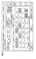
- Fig. 1 is a diagram illustrating an item selection screen used to issue a request for measurement items.
- samples to be measured are selected.
- an automatic selection radio button 1-2 a diluted sample is preferentially measured, and if the amount of a diluted sample is short, a parent sample thereof is used for measurement.
- a manual selection radio button 1-3 three kinds of settings are available.
- the first one of the settings is associated with a case where a parent sample check box 1-4 is selected. In this case, only a parent sample is used for measurement.
- This setting is used for first measurement, or when the parent sample residual is stored, it is used as remeasurement for measurement items for which measurements will be too low in sensitivity to make a precise measurement if a diluted sample is used for measurement.
- the second one of the settings is associated with a case where a diluted sample check box 1-5 is selected.
- a diluted sample is used for measurement.
- the diluted sample check box 1-5 can be selected only when a diluted sample is prepared and diluted sample discard conditions are not satisfied.
- the diluted sample check box 1-5 is used for measurement of an additional measurement item, and for remeasurement of a measurement item for which no trouble is caused in measurement even if a diluted sample is used for measurement.
- the third one of the settings is associated with a case where both the parent sample check box 1-4 and the diluted sample check box 1-5 are selected. In this case, both a parent sample and a diluted sample are used.
- the third setting is used for, for example, a case where the amount of a diluted sample is not sufficient although the second setting is satisfied.
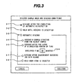
- Inputting a diluted sample button 1-6 displays diluted sample hold and discard conditions setting screen shown in Fig. 3 .
- This button is used to perform three kinds of settings of diluted sample hold and discard conditions.
- the first one of the settings of diluted sample hold and discard conditions is associated with a case where a radio button 3-1 is selected for discarding a diluted sample after the completion of automatic reinspection.
- a radio button 3-1 is selected for discarding a diluted sample after the completion of automatic reinspection.
- a diluted sample is discarded after first measurement is executed and automatic reinspection of the first measurement is completed. In this case, remeasurement of the diluted sample cannot be carried out.
- the second one of the settings is associated with a case where a radio button 3-2 is selected for holding a diluted sample until its discard is specified. According to the second setting, a diluted sample is held until the diluted sample is discarded based on discard specification to be performed on a pre-analysis check screen (shown in Fig. 4 ). The second setting is used when an operator determines timing at which a diluted sample is to be discarded.
- the third one of the settings is associated with a case where a radio button 3-3 is selected for automatically discarding a diluted sample.
- Several discard conditions can be set in the third setting.
- a radio button 3-4 is selected for discarding a sample starting from the oldest one
- a diluted sample is automatically discarded starting from the oldest one such that a diluted sample vessel is empty and thereby trouble is not caused in measurement by the automatic analyzer.
- a radio button 3-5 is selected for discarding a diluted sample after the lapse of a specified period of time, a diluted sample for which the specified time inputted into a specified time edit box 3-6 has elapsed is automatically discarded.
- a check box 3-7 when a check box 3-7 is selected for discarding a diluted sample after measurement succeeds, a sample is discarded after all requested measurement items succeed.
- a check box 3-8 is selected for holding a diluted sample when item is selected, if a requested measurement item remains unmeasured, a sample is not discarded even if discard conditions are satisfied. The use of these condition settings makes it possible to flexibly handle discarding operations of a diluted sample.
- diluted sample selection settings can be made irrespective of before or after the operation of the automatic analyzer, diluted samples are adapted for various kinds of operation modes.
- Fig. 4 is a diagram illustrating a pre-analysis check screen.
- An indication 4-1 schematically shows a pipetted sample disk while an indication 4-2 schematically shows a diluted sample vessel.
- the indications 4-2 expressing diluted sample vessels are disposed on the indication 4-1 expressing the pipetted sample disk 4-1.
- measurement item names for which measurement cannot be performed are listed based on the amount of diluted sample, the amount of reagent, the amount of diluent, the amount of washing agent, and a requested measurement item, which are known at present.
- a combo box 4-3 showing an amount of sample lists names of measurement items for which measurement cannot be performed due to the shortage in the amount of diluted sample.
- a combo box 4-4 showing an amount of reagent lists names of measurement items for which measurement cannot be performed due to the shortage in the amount of reagent.
- a combo box 4-5 showing an amount of diluent lists names of measurement items for which measurement cannot be performed due to the shortage in the amount of diluent.
- a combo box 4-6 showing an amount of washing agent lists names of measurement items for which measurement cannot be performed due to the shortage in the amount of washing agent.
- combo boxes allow an operator to eliminate causes for which a sample cannot be subjected to measurement before the execution of the measurement, or to accept or reject each measurement item.
- a measurement-completion time text 4-7 is displayed by a measurement-completion time text 4-7.
- the remaining amount and the elapsed time after pipetting are displayed by a pipetted sample list box 4-8 for a diluted sample for each diluted sample.
- the remaining amount is to be displayed, the insufficient remaining amount is highlighted with a different color.
- the elapsed time is to be displayed, the elapsed time which has passed the discard specification time is highlighted with a different color.
- a diluted sample can be discarded.
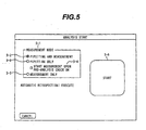
- Fig. 5 is a diagram illustrating an analysis start screen.
- the analysis start screen is used to specify the start of measurement.
- a mode can be selected from among the following three modes.
- a first mode is associated with a case where a pipetting and measurement radio button 5-2 is selected.
- the first mode is a mode in which both pipetting from a parent sample and measurement are executed.
- the second mode is associated with a case where a pipetting-only radio button 5-3 is selected.
- the second mode is a mode in which only pipetting from a parent sample is executed.
- a start button 5-6 When a start button 5-6 is selected to execute only pipetting of the diluted sample from the parent sample in the second mode, it becomes possible to make a check in the pre-analysis check screen shown in Fig. 4 even in first measurement. If a check box 5-4 for starting measurement upon pre-analysis check OK is selected, measurement can be automatically started when all measurement items is judged to be measured by the pre-analysis check.
- the third mode is associated with a case where a measurement-only radio button 5-5 is selected.
- the third mode is a mode in which only measurement is executed. The measurement may be executed after the check and adjustment performed on the pre-analysis check screen shown in Fig. 4 .
- the diluted sample vessels are located in the diluted sample vessel holding unit.
- vessels included in a reaction disk or a reagent disk may also be used for a diluted sample vessel.
- vessels may be circularly placed in two or three layers on a reaction disk with diluted sample vessels and reaction vessels placed in combination.
- the present invention can be used for a wide range of automatic analyzers, each of which is capable of handling a diluted sample, capable of measuring a plurality of items for a sample, and capable of holding a sample pipetted from a parent sample.
Abstract
Description
- The present invention relates to automatic analyzers for performing qualitative/quantitative analysis of samples such as blood and urine. The invention more particularly relates to an automatic analyzer including: a parent sample vessel holding unit for holding a parent sample; a diluted sample vessel holding unit in which a diluted sample vessel is placed, the diluted sample vessel holding a diluted sample made by diluting, with diluent, a sample pipetted from the parent sample; and a reaction vessel in which the analysis, inspection, and measurement of the diluted sample are performed.
- When the analysis and inspection are performed by an automatic analyzer, a plurality of measurement items of the analysis and inspection are requested for one patient sample. Here, in the case of analysis of the very small amount of sample such as a patient whose blood-collecting amount is limited (for example, a newborn baby and a little child), and an experimental small animal, all requested measurement items may not be completely measured because the fluid volume is small.
- As measures against the above problem, for example,
JP-A-8-194004 - The above-described automatic analyzer stores, in a diluted sample vessel, a diluted sample that remains after analysis and inspection to thereby meet a request for reinspection. However, after a lapse of an excessively long period of time, the diluted sample may dry and adhere to a diluted sample vessel, which leads to a difficulty in washing and leads to a deterioration of the diluted sample itself. Consequently the diluted sample will become unsuitable for the qualitative/quantitative analysis and inspection.
- The present invention has been made taking the above-described problems into consideration. An object of the present invention is to provide an automatic analyzer that hardly creates inconveniences including a case where a diluted sample becomes unsuitable for the qualitative/quantitative analysis and inspection because of the adhesion of the diluted sample due to drying, and because of the deterioration of the diluted sample.
- In addition, another object of the present invention is to provide an automatic analyzer that is capable of checking, before measurement for the analysis and inspection is executed, whether or not all requested measurement items for the analysis and inspection can be completely measured, and that is capable of checking, before measurement for the analysis and inspection is executed, the time it takes before measurement of all samples is completed.
- According to one aspect of the present invention, there is provided an automatic analyzer for performing the analysis and inspection of various kinds of samples including a parent sample, a diluted sample, and a combination sample in which the diluted sample and the parent sample are used in combination, said automatic analyzer comprising:
- a parent sample vessel holding unit in which a parent sample vessel containing a parent sample is placed; and
- a diluted sample vessel holding unit in which a diluted sample vessel containing a diluted sample made by diluting the parent sample is placed;
- In addition, according to another aspect of the present invention, there is provided an automatic analyzer for performing the analysis and inspection of various kinds of samples including a parent sample, a diluted sample, and a combination sample in which the diluted sample and the parent sample are used in combination, said automatic analyzer comprising:
- a parent sample vessel holding unit in which a parent sample vessel containing a parent sample is placed; and
- a diluted sample vessel holding unit in which a diluted sample vessel containing a diluted sample made by diluting the parent sample is placed,
- said automatic analyzer having a function of, before the analysis and inspection, knowing how many times and how much the analysis and inspection can be executed on the basis of the amount of the diluted sample that has been diluted.
- In addition, according to the present invention, the automatic analyzer further includes a display unit for displaying, on a screen, various kinds of information about the analysis and inspection. For the analysis and inspection of the diluted sample, the estimated length of time it takes to complete the analysis and inspection of the whole requested diluted sample is displayed on the display unit.
- According to the present invention, the automatic analyzer has afunction of discarding, from the diluted sample vessel, the remaining diluted sample that remains after pipetting in analysis and inspection, and holding the remaining diluted sample in the diluted sample vessel. The automatic analyzer, therefore, can meet a request for remeasurement using the remaining diluted sample. If the elapsed time during which a diluted sample is held becomes too long, the diluted sample is discarded. This makes it possible to make full use of the diluted sample, and to prevent a failure of measurement for the reanalysis and reinspection from occurring which would result from the adhesion of a diluted sample to the diluted sample vessel due to drying and the deterioration of the diluted sample.
- Moreover, according to the present invention, the automatic analyzer is capable of, before the analysis and inspection, knowing how many times and how much the analysis and inspection can be performed on the basis of the amount of the diluted sample that has been diluted, and is capable of displaying, on the display unit, the estimated length of time it takes to complete the analysis and inspection of the whole requested diluted sample. This enables an operator to easily handle various kinds of requested items for the analysis and inspection. As a result, the work efficiency of the operator is improved, which leads to a reduction in diagnosis time for each patient in a hospital.
- Preferred embodiments of the invention are characterized in the sub-claims.
- Embodiments of the present invention are now described with reference to drawings in which:
-
Fig. 1 is a diagram illustrating an item selection screen used to request measurement items that are displayed on a display unit included in an operation unit of an automatic analyzer according to an embodiment of the present invention; -
Fig. 2 is a diagram schematically illustrating the overall configuration of an automatic analyzer based on principles according to the embodiment of the present invention; -
Fig. 3 is a diagram illustrating a diluted sample hold and discard conditions setting screen according to the embodiment of the present invention; -
Fig. 4 is a diagram illustrating a pre-analysis check screen used to check before measurement whether or not each diluted sample can be measured according to the embodiment of the present invention; and -
Fig. 5 is a diagram illustrating an analysis start screen used to start measurement of samples such as a diluted sample according to the embodiment of the present invention. - 1. For the reanalysis, reinspection, and remeasurement of a sample subjected to measurement has been completed, which are to be manually performed, a situation in which the remeasurement cannot be executed due to the shortage of the sample is avoided.
More specifically, a parent sample is diluted with diluent to increase the amount of sample so that many analysis and inspection items for the reanalysis, reinspection, and remeasurement can be handled (hereinafter the analysis and inspection are also merely called "measurement"). In addition, the diluted sample is held over a period of time during which the diluted sample can be used for the analysis and inspection; and if the elapsed time during which the diluted sample is held becomes too long, the diluted sample is discarded. - 2. How many times the analysis and inspection can be performed is estimated on the basis of the amount of the diluted sample before the execution of measurement. In addition, the length of time it takes to complete measurement of the whole sample can be known.
- 3. A display unit is used to display: an item selection screen used to request measurement of each measurement item; an analysis start screen used to start the measurement; and a pre-analysis check screen used to make a check before the measurement. Thus, the analysis and inspection can be easily performed.
-
Fig. 2 is a diagram schematically illustrating the overall configuration of an automatic analyzer based on principles. - In
Fig. 2 , reference numeral 2-1 denotes an operation unit. The operation unit 2-1 is a computer equipped with peripheral devices. The peripheral devices are a keyboard 2-2 for inputting data; a mouse 2-3; a display unit for displaying data 2-4; a printer 2-5 for printing data; an interface 2-6 through which a connection to an analyzing unit is made; and a storage device 2-7 for storing hold and discard conditions of a diluted sample and a state of the diluted sample.
Reference numeral 2-8 denotes an analyzing unit. The analyzing unit 2-8 is connected to the operation unit 2-1 through the interface 2-6. - The analyzing unit 2-8 includes a reaction disk 2-9. A plurality of reaction vessels 2-10 are disposed along the concentric circumference of the reaction disk 2-9. Reference numeral 2-11 denotes a reagent disk. A plurality of reagent bottles 2-12 containing various kinds of reagents are disposed along the concentric circumference of the reagent disk 2-11. Around the reaction disk 2-9 disposed are a pipetting probe 2-13 for pipetting a diluted sample into the reaction disk 2-9; a mixer 2-14; a cleaning device 2-15; a light source 2-16; and a multiwavelength photometer 2-17.
- A reagent pipetting probe 2-18 is disposed between the reaction disk 2-9 and the reagent disk 2-11.
In addition, a diluted sample disk 2-19 is disposed at a position adjacent to the reagent disk 2-11 in such a manner that the diluted sample disk 2-19 is associated with the circumference of the rotating diluted sample pipetting probe 2-13. A plurality of diluted sample vessels 2-20 each containing a diluted sample are located on the diluted sample disk 2-19. - The reagent disk 2-11 has the plurality of reagent bottles 2-12 thereon, each of which contains a reagent used to dilute a sample and/or a reagent used to analyze and inspect a sample. Further, a rack transfer belt 2-24 is extended at a position adjacent to the diluted sample disk 2-19. A rack 2-22 moves along the rack transfer belt 2-24. A plurality of parent sample vessels 2-23 each containing a parent sample are placed in the rack 2-22.
- A parent sample pipetting probe 2-21 is disposed between the diluted sample disk 2-19 and the rack transfer belt 2-24. The operation of the above-described mechanism is totally controlled by the computer 2-26 through the interface 2-25.
- An operator uses the display unit 2-4 and the keyboard 2-2 (or the mouse 2-3) that are included in the operation unit 2-1 to give the analyzer a measurement instruction including requested measurement items. The measurement instruction is transmitted to the analyzing unit 2-8 through the interface 2-6. According to the received measurement instruction, the analyzing unit 2-8 makes measurements in the following manner.
- The parent sample pipetting probe 2-21 pipettes, into the diluted sample vessel 2-20, the specified amount of parent sample contained in the parent sample vessel 2-23. On the completion of pipetting the whole amount of parent sample contained in one parent sample vessel 2-23, the rack transfer belt 2-24 moves the rack 2-22 such that the next parent sample vessel 2-23 comes to a position immediately below the parent sample pipetting probe 2-21.
- On the completion of pipetting the whole amount of parent sample from all of the parent sample vessels 2-23 placed on the rack 2-22, the rack 2-22 is carried out by the rack transfer belt 2-24. During this operation, a diluent for diluting a sample contained in the diluted sample vessel 2-20 is pipetted. More specifically, the reagent pipetting probe 2-18 sucks the diluent contained in the reagent bottle 2-12, and then puts the sucked diluent into the diluted sample vessel 2-20, whereby the sample is diluted.
- The diluted sample pipetting probe 2-13 pipettes the specified amount of diluted sample contained in the diluted sample vessel 2-20 into each reaction vessel 2-10 such that the required number of items is satisfied.
- On the completion of pipetting the whole amount of diluted sample contained in one diluted sample vessel 2-20, the diluted sample disk 2-19 is rotated such that the next diluted sample vessel 2-20 comes at a position immediately below the diluted sample pipetting probe 2-13. The rotational operation of the reaction disk 2-9 causes the reaction vessel 2-10, into which a diluted sample has been pipetted, to rotationally move on the reaction disk 2-9.
- During this operation, the reagent pipetting probe 2-18 pipets a reagent contained in the reagent bottle 2-12 into the reaction vessel 2-10 containing the sample; the mixer 2-14 stirring the reaction solution; and the multiwavelength photometer 2-17 measures the absorbance by use of the light source 2-16. After that, the cleaning device 2-15 cleans the reaction vessel 2-10 whose measurements have been completed.
- The absorbance signal representing the measured absorbance is inputted into the computer 2-26 through the A/D converter 2-27 and the interface 2-25. From this absorbance signal, on the basis of an analysis method that is set beforehand for each measurement item, calibration curve data is calculated for a standard solution sample from concentration data that is set, whereas concentration data is calculated from t for a patient sample and a control sample he calibration curve data obtained by the measurements of the standard solution sample.
- After information obtained by symbolizing a kind of the sample is added to the thus-obtained pieces of data, they are transmitted as measurements to the operation unit 2-1 through the interface 2-6.
- In the above-described operation, the display unit 2-4 and the keyboard 2-2 (and/or the mouse 2-3) are used to execute the following processing: manually remeasuring measured samples; setting diluted sample hold and discard conditions; viewing unmeasurable measurement items; and viewing the length of time it takes until measurement of the whole requested diluted sample is completed.
-
Fig. 1 is a diagram illustrating an item selection screen used to issue a request for measurement items. - In specification of samples to be measured 1-1, samples to be measured are selected.
When an automatic selection radio button 1-2 is selected, a diluted sample is preferentially measured, and if the amount of a diluted sample is short, a parent sample thereof is used for measurement. When a manual selection radio button 1-3 is selected, three kinds of settings are available. - The first one of the settings is associated with a case where a parent sample check box 1-4 is selected. In this case, only a parent sample is used for measurement. This setting is used for first measurement, or when the parent sample residual is stored, it is used as remeasurement for measurement items for which measurements will be too low in sensitivity to make a precise measurement if a diluted sample is used for measurement.
- The second one of the settings is associated with a case where a diluted sample check box 1-5 is selected. In this case, only a diluted sample is used for measurement. The diluted sample check box 1-5 can be selected only when a diluted sample is prepared and diluted sample discard conditions are not satisfied. For example, the diluted sample check box 1-5 is used for measurement of an additional measurement item, and for remeasurement of a measurement item for which no trouble is caused in measurement even if a diluted sample is used for measurement.
- The third one of the settings is associated with a case where both the parent sample check box 1-4 and the diluted sample check box 1-5 are selected. In this case, both a parent sample and a diluted sample are used. The third setting is used for, for example, a case where the amount of a diluted sample is not sufficient although the second setting is satisfied.
- Inputting a diluted sample button 1-6 displays diluted sample hold and discard conditions setting screen shown in
Fig. 3 . This button is used to perform three kinds of settings of diluted sample hold and discard conditions. - The first one of the settings of diluted sample hold and discard conditions is associated with a case where a radio button 3-1 is selected for discarding a diluted sample after the completion of automatic reinspection. According to the first setting, a diluted sample is discarded after first measurement is executed and automatic reinspection of the first measurement is completed. In this case, remeasurement of the diluted sample cannot be carried out.
- The second one of the settings is associated with a case where a radio button 3-2 is selected for holding a diluted sample until its discard is specified. According to the second setting, a diluted sample is held until the diluted sample is discarded based on discard specification to be performed on a pre-analysis check screen (shown in
Fig. 4 ). The second setting is used when an operator determines timing at which a diluted sample is to be discarded. - The third one of the settings is associated with a case where a radio button 3-3 is selected for automatically discarding a diluted sample. Several discard conditions can be set in the third setting. When a radio button 3-4 is selected for discarding a sample starting from the oldest one, a diluted sample is automatically discarded starting from the oldest one such that a diluted sample vessel is empty and thereby trouble is not caused in measurement by the automatic analyzer. When a radio button 3-5 is selected for discarding a diluted sample after the lapse of a specified period of time, a diluted sample for which the specified time inputted into a specified time edit box 3-6 has elapsed is automatically discarded.
- This makes it possible to prevent a sample, which has been degraded due to the lapse of time, from being measured. Thus, the reliability of measurements can be increased.
- In addition, when a check box 3-7 is selected for discarding a diluted sample after measurement succeeds, a sample is discarded after all requested measurement items succeed. When a check box 3-8 is selected for holding a diluted sample when item is selected, if a requested measurement item remains unmeasured, a sample is not discarded even if discard conditions are satisfied.
The use of these condition settings makes it possible to flexibly handle discarding operations of a diluted sample. - Because diluted sample selection settings can be made irrespective of before or after the operation of the automatic analyzer, diluted samples are adapted for various kinds of operation modes.
-
Fig. 4 is a diagram illustrating a pre-analysis check screen. By use of the pre-analysis check screen, it is possible to know, before the start of measurement, whether or not requested measurement items can be measured, and to know the length of time it takes until all measurements are completed. An indication 4-1 schematically shows a pipetted sample disk while an indication 4-2 schematically shows a diluted sample vessel. The indications 4-2 expressing diluted sample vessels are disposed on the indication 4-1 expressing the pipetted sample disk 4-1. With the pre-analysis check screen, if the amount of diluted sample, the amount of reagent to be used, the amount of diluent, or the amount of washing agent is insufficient, they are highlighted with color and patterns in accordance with the causes of insufficiency. - In addition, when the indication 4-2 is selected, measurement item names for which measurement cannot be performed are listed based on the amount of diluted sample, the amount of reagent, the amount of diluent, the amount of washing agent, and a requested measurement item, which are known at present.
- A combo box 4-3 showing an amount of sample lists names of measurement items for which measurement cannot be performed due to the shortage in the amount of diluted sample. A combo box 4-4 showing an amount of reagent lists names of measurement items for which measurement cannot be performed due to the shortage in the amount of reagent. A combo box 4-5 showing an amount of diluent lists names of measurement items for which measurement cannot be performed due to the shortage in the amount of diluent. A combo box 4-6 showing an amount of washing agent lists names of measurement items for which measurement cannot be performed due to the shortage in the amount of washing agent.
- The above-described combo boxes allow an operator to eliminate causes for which a sample cannot be subjected to measurement before the execution of the measurement, or to accept or reject each measurement item.
- Moreover, the length of time it takes until measurement of all samples is completed is displayed by a measurement-completion time text 4-7. The remaining amount and the elapsed time after pipetting are displayed by a pipetted sample list box 4-8 for a diluted sample for each diluted sample. When the remaining amount is to be displayed, the insufficient remaining amount is highlighted with a different color. Likewise, when the elapsed time is to be displayed, the elapsed time which has passed the discard specification time is highlighted with a different color.
- Further, when the pipetted sample list box 4-8 for a diluted sample is selected and then a discard button 4-10 is selected, a diluted sample can be discarded.
-
Fig. 5 is a diagram illustrating an analysis start screen. The analysis start screen is used to specify the start of measurement. In measurement mode 5-1, a mode can be selected from among the following three modes. - A first mode is associated with a case where a pipetting and measurement radio button 5-2 is selected. The first mode is a mode in which both pipetting from a parent sample and measurement are executed.
- The second mode is associated with a case where a pipetting-only radio button 5-3 is selected. The second mode is a mode in which only pipetting from a parent sample is executed.
- When a start button 5-6 is selected to execute only pipetting of the diluted sample from the parent sample in the second mode, it becomes possible to make a check in the pre-analysis check screen shown in
Fig. 4 even in first measurement. If a check box 5-4 for starting measurement upon pre-analysis check OK is selected, measurement can be automatically started when all measurement items is judged to be measured by the pre-analysis check. - The third mode is associated with a case where a measurement-only radio button 5-5 is selected. The third mode is a mode in which only measurement is executed. The measurement may be executed after the check and adjustment performed on the pre-analysis check screen shown in
Fig. 4 . - In the above-described embodiment, the diluted sample vessels are located in the diluted sample vessel holding unit. However, vessels included in a reaction disk or a reagent disk may also be used for a diluted sample vessel. In addition, vessels may be circularly placed in two or three layers on a reaction disk with diluted sample vessels and reaction vessels placed in combination.
- The present invention can be used for a wide range of automatic analyzers, each of which is capable of handling a diluted sample, capable of measuring a plurality of items for a sample, and capable of holding a sample pipetted from a parent sample.
Claims (14)
- An automatic analyzer for performing the analysis and inspection of various kinds of samples including a parent sample, a diluted sample, and a combination sample in which the diluted sample and the parent sample are used in combination, said automatic analyzer comprising:a parent sample vessel holding unit in which a parent sample vessel containing a parent sample is placed; anda diluted sample vessel holding unit in which a diluted sample vessel containing a diluted sample made by diluting the parent sample is placed;wherein said automatic analyzer has means for discarding, from the diluted sample vessel, the remaining diluted sample that remains after pipetting in the analysis and inspection, and holding the remaining diluted sample in the diluted sample vessel.
- The automatic analyzer according to Claim 1, further comprising means for selecting, irrespective of before or after the start of the operation of the automatic analyzer, discarding or holding of the diluted sample.
- An automatic analyzer for performing the analysis and inspection of various kinds of samples including a parent sample, a diluted sample, and a combination sample in which the diluted sample and the parent sample are used in combination, said automatic analyzer comprising:a parent sample vessel holding unit in which a parent sample vessel containing a parent sample is placed; anda diluted sample vessel holding unit in which a diluted sample vessel containing a diluted sample made by diluting the parent sample is placed;wherein said automatic analyzer has means for knowing, before the analysis and inspection, how many times and how much the analysis and inspection can be executed on the basis of the amount of the diluted sample.
- The automatic analyzer according to Claim 3, further comprising means for determining, before the analysis and inspection, items which can be analyzed and inspected, from various kinds of requested items for the analysis and inspection.
- The automatic analyzer according to Claim 1, comprising means for selecting various kinds of samples for the analysis and inspection, the various kinds of samples including the diluted sample, the parent sample, and a combination sample in which the diluted sample and the parent sample are used in combination.
- The automatic analyzer according to Claim 1, comprising means for setting hold and discard conditions for the diluted sample.
- The automatic analyzer according to Claim 1, comprising means for specifying a diluted sample vessel containing a diluted sample to be discarded from among the plurality of diluted sample vessels placed in the diluted sample vessel holding unit.
- The automatic analyzer according to Claim 1, comprising means for specifying the elapsed time or the time as the timing at which the diluted sample is to be discarded.
- The automatic analyzer according to Claim 1, further comprising a display unit for displaying, on a screen, various kinds of information about the analysis and inspection,
wherein information including the elapsed time and remaining amount of the diluted sample is provided by use of the display unit. - The automatic analyzer according to Claim 1, further comprising a pipetter for pipetting a parent sample from the parent sample vessel into the diluted sample vessel,
wherein a specific parent sample vessel to be used for pipetting by the pipetter can be specified from among a plurality of existing parent sample vessels. - The automatic analyzer according to Claim 1, further including means for selecting various kinds of samples for the analysis and inspection, the various kinds of samples including the diluted sample, the parent sample, and a combination sample in which the diluted sample and the parent sample are used in combination,
wherein the diluted sample can be selected on the conditions that the diluted sample exists, and that discarding of the diluted sample is not set. - The automatic analyzer according to Claim 9, further comprising a display unit for displaying, on a screen, various kinds of information about the analysis and inspection,
wherein for the analysis and inspection of the diluted sample, the estimated length of time it takes to complete the analysis and inspection of the whole requested diluted sample is displayed on the display unit. - The automatic analyzer according to Claim 1, further comprising a display unit for displaying, on a screen, various kinds of information about the analysis and inspection,
wherein for the analysis and inspection of the diluted sample, whether or not the amount of sample, the amount of reagent, the amount of diluent, the amount of washing agent, and the like, are sufficient for the completion of all the requested analysis and inspection is displayed on the display unit using a display technique such as characters, colors, and marks. - The automatic analyzer according to Claim 1, further including means for specifying an automatic start of the analysis and inspection, even when the amount of sample, the amount of reagent, the amount of diluent, the amount of washing agent, and the like, are sufficient for the completion of all the requested analysis and inspection and the pipetting operation of pipetting from the specified parent sample vessel into the diluted sample vessel is completed.
Applications Claiming Priority (1)
| Application Number | Priority Date | Filing Date | Title |
|---|---|---|---|
| JP2008046172A JP4659054B2 (en) | 2008-02-27 | 2008-02-27 | Automatic analyzer |
Publications (3)
| Publication Number | Publication Date |
|---|---|
| EP2096446A2 true EP2096446A2 (en) | 2009-09-02 |
| EP2096446A3 EP2096446A3 (en) | 2011-02-23 |
| EP2096446B1 EP2096446B1 (en) | 2017-07-19 |
Family
ID=40792602
Family Applications (1)
| Application Number | Title | Priority Date | Filing Date |
|---|---|---|---|
| EP09150640.2A Active EP2096446B1 (en) | 2008-02-27 | 2009-01-15 | Automatic analyzer |
Country Status (4)
| Country | Link |
|---|---|
| US (1) | US8343423B2 (en) |
| EP (1) | EP2096446B1 (en) |
| JP (1) | JP4659054B2 (en) |
| CN (1) | CN101520465B (en) |
Cited By (1)
| Publication number | Priority date | Publication date | Assignee | Title |
|---|---|---|---|---|
| CN106104043A (en) * | 2014-03-17 | 2016-11-09 | 舍弗勒技术股份两合公司 | Clutch disc support and the clutch apparatus with this clutch disc support |
Families Citing this family (26)
| Publication number | Priority date | Publication date | Assignee | Title |
|---|---|---|---|---|
| JP5431755B2 (en) * | 2008-10-31 | 2014-03-05 | シスメックス株式会社 | Sample analyzer and sample analysis method |
| EP2485054B1 (en) * | 2009-09-28 | 2019-08-21 | Hitachi High-Technologies Corporation | Automatic analyzing device, information display method thereof, and information display system |
| WO2011066269A1 (en) | 2009-11-24 | 2011-06-03 | Siemens Healthcare Diagnostics Inc. | Automated, refrigerated specimen inventory management system |
| JP5591742B2 (en) | 2010-06-30 | 2014-09-17 | シスメックス株式会社 | Specimen Testing Device Processing Capacity Information Generation Device, Specimen Testing Apparatus, Specimen Testing Device Processing Capacity Information Generation Method, and Computer Program |
| JP5686710B2 (en) * | 2011-09-21 | 2015-03-18 | 株式会社日立ハイテクノロジーズ | Automatic analyzer |
| JP2013167561A (en) * | 2012-02-16 | 2013-08-29 | Hitachi High-Technologies Corp | Automatic analyzer |
| JP6072450B2 (en) * | 2012-07-12 | 2017-02-01 | 株式会社日立ハイテクノロジーズ | Automatic analyzer |
| JP6177532B2 (en) * | 2013-01-23 | 2017-08-09 | 株式会社日立ハイテクノロジーズ | Automatic analysis system and control method |
| CN109358202B (en) | 2013-03-15 | 2023-04-07 | 雅培制药有限公司 | Automated diagnostic analyzer with vertically arranged carousel and related methods |
| JP6165961B2 (en) | 2013-03-15 | 2017-07-19 | アボット・ラボラトリーズAbbott Laboratories | Diagnostic analyzer with pre-process carousel and associated method |
| CN114137240A (en) | 2013-03-15 | 2022-03-04 | 雅培制药有限公司 | Automated diagnostic analyzer with rear accessible track system and related methods |
| JP5951545B2 (en) * | 2013-03-29 | 2016-07-13 | シスメックス株式会社 | Sample analyzer, sample analysis method, and computer program |
| JP6259663B2 (en) * | 2014-01-07 | 2018-01-10 | 株式会社日立ハイテクノロジーズ | Automatic analyzer |
| US10895579B2 (en) * | 2015-03-02 | 2021-01-19 | Hitachi High-Tech Corporation | Automatic analyzer |
| JP6771903B2 (en) * | 2016-02-29 | 2020-10-21 | シスメックス株式会社 | Specimen pretreatment device, sample pretreatment cartridge and sample pretreatment method |
| US11125765B2 (en) * | 2016-09-21 | 2021-09-21 | Hitachi High-Tech Corporation | Automatic analyzer |
| JP6909224B2 (en) * | 2016-09-21 | 2021-07-28 | 株式会社日立ハイテク | Automatic analyzer and remote maintenance system and maintenance method |
| JP6788745B2 (en) * | 2017-07-25 | 2020-11-25 | 株式会社日立ハイテク | Automatic analyzer |
| JP6742963B2 (en) | 2017-07-25 | 2020-08-19 | 株式会社日立ハイテク | Automatic analyzer and image processing method |
| CN109959549A (en) * | 2017-12-25 | 2019-07-02 | 深圳迈瑞生物医疗电子股份有限公司 | Sample testing method and sample analyser |
| JP2019120572A (en) * | 2018-01-04 | 2019-07-22 | 日本電子株式会社 | Automatic analyzer and re-inspection instruction system |
| JP6843800B2 (en) * | 2018-06-19 | 2021-03-17 | 日本電子株式会社 | Automatic analyzer and automatic analysis method |
| EP3834204A1 (en) * | 2018-08-09 | 2021-06-16 | FOSS Analytical A/S | Analysis instrument |
| EP3872498A4 (en) * | 2018-10-23 | 2022-07-13 | Sekisui Medical Co., Ltd. | Autosampler, automatic analysis device, sampling method, and automatic inspection method |
| WO2020085272A1 (en) * | 2018-10-23 | 2020-04-30 | 積水メディカル株式会社 | Autosampler, automatic analysis device, sampling method, and automatic inspection method |
| CN112577952A (en) * | 2019-09-30 | 2021-03-30 | 深圳迈瑞生物医疗电子股份有限公司 | Sample analysis device and sample dilution test method |
Citations (1)
| Publication number | Priority date | Publication date | Assignee | Title |
|---|---|---|---|---|
| JPH08194004A (en) | 1995-01-19 | 1996-07-30 | Jeol Ltd | Instrument for biochemical automatic analysis |
Family Cites Families (13)
| Publication number | Priority date | Publication date | Assignee | Title |
|---|---|---|---|---|
| JP2708437B2 (en) * | 1987-11-13 | 1998-02-04 | 株式会社日立製作所 | Automatic analyzer |
| JP2539512B2 (en) * | 1989-07-17 | 1996-10-02 | 株式会社日立製作所 | Multi-item analyzer and method for operating the analyzer |
| JPH03140844A (en) * | 1989-10-26 | 1991-06-14 | Shimadzu Corp | Multi-item analysis of minute sample |
| US5314825A (en) | 1992-07-16 | 1994-05-24 | Schiapparelli Biosystems, Inc. | Chemical analyzer |
| JP2950698B2 (en) * | 1993-01-11 | 1999-09-20 | 株式会社日立製作所 | Automatic analyzer with washing function |
| JPH0798320A (en) | 1993-09-29 | 1995-04-11 | Shimadzu Corp | Biochemical automatic analyzer |
| JPH08278313A (en) | 1995-04-06 | 1996-10-22 | Toshiba Medical Eng Co Ltd | Automatic chemical analysis device |
| US5741461A (en) * | 1995-05-19 | 1998-04-21 | Hitachi, Ltd. | Automatic analyzer having cuvette cleaning control device |
| JP3156550B2 (en) * | 1995-07-11 | 2001-04-16 | 株式会社日立製作所 | Reagent management method and apparatus |
| JP3419430B2 (en) * | 1996-08-21 | 2003-06-23 | 日本電子株式会社 | Reagent injection mixer for biochemical automatic analyzer |
| JP3558898B2 (en) * | 1998-11-05 | 2004-08-25 | 株式会社日立製作所 | Automatic analyzer and automatic analysis method |
| JP2000321283A (en) * | 1999-05-13 | 2000-11-24 | Toshiba Corp | Automatic analyzer |
| JP4595825B2 (en) | 2006-01-30 | 2010-12-08 | 株式会社島津製作所 | Data processor for automatic analysis |
-
2008
- 2008-02-27 JP JP2008046172A patent/JP4659054B2/en active Active
- 2008-12-17 US US12/336,968 patent/US8343423B2/en active Active
-
2009
- 2009-01-15 EP EP09150640.2A patent/EP2096446B1/en active Active
- 2009-02-19 CN CN2009100075007A patent/CN101520465B/en active Active
Patent Citations (1)
| Publication number | Priority date | Publication date | Assignee | Title |
|---|---|---|---|---|
| JPH08194004A (en) | 1995-01-19 | 1996-07-30 | Jeol Ltd | Instrument for biochemical automatic analysis |
Cited By (2)
| Publication number | Priority date | Publication date | Assignee | Title |
|---|---|---|---|---|
| CN106104043A (en) * | 2014-03-17 | 2016-11-09 | 舍弗勒技术股份两合公司 | Clutch disc support and the clutch apparatus with this clutch disc support |
| CN106104043B (en) * | 2014-03-17 | 2019-08-27 | 舍弗勒技术股份两合公司 | Clutch disc bracket and clutch apparatus with this clutch disc bracket |
Also Published As
| Publication number | Publication date |
|---|---|
| JP4659054B2 (en) | 2011-03-30 |
| CN101520465A (en) | 2009-09-02 |
| JP2009204409A (en) | 2009-09-10 |
| CN101520465B (en) | 2013-07-10 |
| US20090214385A1 (en) | 2009-08-27 |
| EP2096446A3 (en) | 2011-02-23 |
| EP2096446B1 (en) | 2017-07-19 |
| US8343423B2 (en) | 2013-01-01 |
Similar Documents
| Publication | Publication Date | Title |
|---|---|---|
| EP2096446A2 (en) | Automatic analyzer | |
| JP3990944B2 (en) | Automatic analyzer | |
| US8329103B2 (en) | Sample analyzer and method for analyzing samples | |
| JP5993865B2 (en) | Automatic analysis system | |
| EP1873530B1 (en) | Sample analyzer | |
| EP1895307A1 (en) | Automated analyzer | |
| JP2008058129A (en) | Autoanalyzer | |
| EP2878956B1 (en) | Automated analyzer | |
| US11054433B2 (en) | Automated analyzer and control method for same | |
| JP4861933B2 (en) | Automatic analyzer | |
| JP7219760B2 (en) | automatic analyzer | |
| JP5686710B2 (en) | Automatic analyzer | |
| WO2016017291A1 (en) | Automatic analysis device | |
| JP5271929B2 (en) | Automatic analyzer | |
| JP2016090239A (en) | Automatic analyzer and automatic analysis method | |
| JP5264851B2 (en) | Automatic analyzer and reagent management method | |
| US11009519B2 (en) | Automated analyzer and image processing method | |
| JP5505983B2 (en) | Automatic analyzer | |
| US20190204347A1 (en) | Automated analyzer and retesting instruction system | |
| JP5763238B2 (en) | Automatic analyzer | |
| JPH09196924A (en) | Automatic analyser | |
| JP2013140103A (en) | Automatic analyzer | |
| JP2007198991A (en) | Autoanalyzer | |
| JP2007322393A (en) | Autoanalyzer, precision control method thereof, and program for precision control |
Legal Events
| Date | Code | Title | Description |
|---|---|---|---|
| PUAI | Public reference made under article 153(3) epc to a published international application that has entered the european phase |
Free format text: ORIGINAL CODE: 0009012 |
|
| 17P | Request for examination filed |
Effective date: 20090129 |
|
| AK | Designated contracting states |
Kind code of ref document: A2 Designated state(s): AT BE BG CH CY CZ DE DK EE ES FI FR GB GR HR HU IE IS IT LI LT LU LV MC MK MT NL NO PL PT RO SE SI SK TR |
|
| AX | Request for extension of the european patent |
Extension state: AL BA RS |
|
| PUAL | Search report despatched |
Free format text: ORIGINAL CODE: 0009013 |
|
| AK | Designated contracting states |
Kind code of ref document: A3 Designated state(s): AT BE BG CH CY CZ DE DK EE ES FI FR GB GR HR HU IE IS IT LI LT LU LV MC MK MT NL NO PL PT RO SE SI SK TR |
|
| AX | Request for extension of the european patent |
Extension state: AL BA RS |
|
| RIC1 | Information provided on ipc code assigned before grant |
Ipc: G01N 35/00 20060101ALI20110118BHEP Ipc: G01N 35/10 20060101AFI20090701BHEP |
|
| AKX | Designation fees paid |
Designated state(s): DE FR |
|
| 17Q | First examination report despatched |
Effective date: 20140512 |
|
| GRAP | Despatch of communication of intention to grant a patent |
Free format text: ORIGINAL CODE: EPIDOSNIGR1 |
|
| INTG | Intention to grant announced |
Effective date: 20161006 |
|
| RIN1 | Information on inventor provided before grant (corrected) |
Inventor name: ORIHASHI, TOSHIHIDE HITACHI HIGH-TECHNOLOGIES Inventor name: MORI, HIROKI HITACHI HIGH-TECHNOLOGIES Inventor name: KANEKO, YASUO HITACHI HIGH-TECHNOLOGIES |
|
| GRAS | Grant fee paid |
Free format text: ORIGINAL CODE: EPIDOSNIGR3 |
|
| GRAA | (expected) grant |
Free format text: ORIGINAL CODE: 0009210 |
|
| AK | Designated contracting states |
Kind code of ref document: B1 Designated state(s): DE FR |
|
| REG | Reference to a national code |
Ref country code: DE Ref legal event code: R096 Ref document number: 602009047165 Country of ref document: DE |
|
| REG | Reference to a national code |
Ref country code: FR Ref legal event code: PLFP Year of fee payment: 10 |
|
| REG | Reference to a national code |
Ref country code: DE Ref legal event code: R097 Ref document number: 602009047165 Country of ref document: DE |
|
| PLBE | No opposition filed within time limit |
Free format text: ORIGINAL CODE: 0009261 |
|
| STAA | Information on the status of an ep patent application or granted ep patent |
Free format text: STATUS: NO OPPOSITION FILED WITHIN TIME LIMIT |
|
| 26N | No opposition filed |
Effective date: 20180420 |
|
| REG | Reference to a national code |
Ref country code: DE Ref legal event code: R082 Ref document number: 602009047165 Country of ref document: DE Representative=s name: PUSCHMANN BORCHERT BARDEHLE PATENTANWAELTE PAR, DE Ref country code: DE Ref legal event code: R081 Ref document number: 602009047165 Country of ref document: DE Owner name: HITACHI HIGH-TECH CORPORATION, JP Free format text: FORMER OWNER: HITACHI HIGH-TECHNOLOGIES CORPORATION, TOKYO, JP Ref country code: DE Ref legal event code: R082 Ref document number: 602009047165 Country of ref document: DE Representative=s name: PUSCHMANN BORCHERT KAISER KLETTNER PATENTANWAE, DE |
|
| PGFP | Annual fee paid to national office [announced via postgrant information from national office to epo] |
Ref country code: FR Payment date: 20221208 Year of fee payment: 15 |
|
| PGFP | Annual fee paid to national office [announced via postgrant information from national office to epo] |
Ref country code: DE Payment date: 20221130 Year of fee payment: 15 |