EP2098882A2 - Location measurement method based on predictive filter - Google Patents
Location measurement method based on predictive filter Download PDFInfo
- Publication number
- EP2098882A2 EP2098882A2 EP09153873A EP09153873A EP2098882A2 EP 2098882 A2 EP2098882 A2 EP 2098882A2 EP 09153873 A EP09153873 A EP 09153873A EP 09153873 A EP09153873 A EP 09153873A EP 2098882 A2 EP2098882 A2 EP 2098882A2
- Authority
- EP
- European Patent Office
- Prior art keywords
- location
- mobile node
- location measurement
- change
- measurement method
- Prior art date
- Legal status (The legal status is an assumption and is not a legal conclusion. Google has not performed a legal analysis and makes no representation as to the accuracy of the status listed.)
- Ceased
Links
- 238000000691 measurement method Methods 0.000 title claims abstract description 52
- 238000005259 measurement Methods 0.000 claims abstract description 107
- 230000008859 change Effects 0.000 claims abstract description 56
- 238000000034 method Methods 0.000 claims description 28
- 238000006073 displacement reaction Methods 0.000 claims description 18
- 239000011159 matrix material Substances 0.000 description 35
- 238000004088 simulation Methods 0.000 description 7
- 238000010586 diagram Methods 0.000 description 6
- 230000003044 adaptive effect Effects 0.000 description 5
- 238000007796 conventional method Methods 0.000 description 4
- 230000008569 process Effects 0.000 description 4
- 238000004364 calculation method Methods 0.000 description 3
- 238000012986 modification Methods 0.000 description 3
- 230000004048 modification Effects 0.000 description 3
- 238000012545 processing Methods 0.000 description 3
- 230000001133 acceleration Effects 0.000 description 2
- 238000004422 calculation algorithm Methods 0.000 description 2
- 238000006243 chemical reaction Methods 0.000 description 2
- 230000007423 decrease Effects 0.000 description 2
- 230000007613 environmental effect Effects 0.000 description 2
- 230000006870 function Effects 0.000 description 2
- 238000004458 analytical method Methods 0.000 description 1
- 230000000694 effects Effects 0.000 description 1
- 230000002708 enhancing effect Effects 0.000 description 1
- 230000006872 improvement Effects 0.000 description 1
- 238000004519 manufacturing process Methods 0.000 description 1
- 230000002250 progressing effect Effects 0.000 description 1
- 230000009467 reduction Effects 0.000 description 1
- 238000011160 research Methods 0.000 description 1
- 230000036962 time dependent Effects 0.000 description 1
- 230000007704 transition Effects 0.000 description 1
Images


Classifications
-
- G—PHYSICS
- G01—MEASURING; TESTING
- G01S—RADIO DIRECTION-FINDING; RADIO NAVIGATION; DETERMINING DISTANCE OR VELOCITY BY USE OF RADIO WAVES; LOCATING OR PRESENCE-DETECTING BY USE OF THE REFLECTION OR RERADIATION OF RADIO WAVES; ANALOGOUS ARRANGEMENTS USING OTHER WAVES
- G01S5/00—Position-fixing by co-ordinating two or more direction or position line determinations; Position-fixing by co-ordinating two or more distance determinations
- G01S5/02—Position-fixing by co-ordinating two or more direction or position line determinations; Position-fixing by co-ordinating two or more distance determinations using radio waves
- G01S5/0294—Trajectory determination or predictive filtering, e.g. target tracking or Kalman filtering
-
- H—ELECTRICITY
- H04—ELECTRIC COMMUNICATION TECHNIQUE
- H04W—WIRELESS COMMUNICATION NETWORKS
- H04W24/00—Supervisory, monitoring or testing arrangements
- H04W24/10—Scheduling measurement reports ; Arrangements for measurement reports
-
- H—ELECTRICITY
- H04—ELECTRIC COMMUNICATION TECHNIQUE
- H04W—WIRELESS COMMUNICATION NETWORKS
- H04W64/00—Locating users or terminals or network equipment for network management purposes, e.g. mobility management
- H04W64/003—Locating users or terminals or network equipment for network management purposes, e.g. mobility management locating network equipment
-
- H—ELECTRICITY
- H04—ELECTRIC COMMUNICATION TECHNIQUE
- H04W—WIRELESS COMMUNICATION NETWORKS
- H04W8/00—Network data management
- H04W8/02—Processing of mobility data, e.g. registration information at HLR [Home Location Register] or VLR [Visitor Location Register]; Transfer of mobility data, e.g. between HLR, VLR or external networks
Definitions
- the present invention relates generally to a location measurement method and, in particular, to a location measurement method of a mobile node using a predictive filter that is capable of improving the location measurement accuracy of the mobile node.
- a predictive filter is used to predict its location using the past measurement information and environmental information.
- a predictive filter based compensation method using past measurements and environmental information, or a finger printing method using previously recorded site-specific signal patterns are used.
- the predictive filter allows estimation of a current location of the mobile node using the past location and state information and compensates for the offset between the measured and predicted locations by adopting weights depending on the reliability of the information.
- a Kalman filter is one of the well known predictive filters. The Kalman filter adjusts a weight applied to a estimated value of a covariance matrix and an actually measured value.
- a mobile node acquires coordinates of at least three anchor nodes and measures periodically the distances from the anchor nodes and then determines coordinates that have the smallest errors from each anchor node through a least square method as the location of the mobile node.
- the acquired coordinates are input to the Kalman filter so as to be output as a compensated coordinates. This method is described in more detail as follows, with reference to FIGs. 1 , 2A, and 2B .
- FIG. 1 is a graph illustrating a simulated result of measurement error compensation using a conventional least square method and Kalman filter
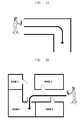
- FIGs. 2a and 2b are conceptual diagrams illustrating examples of movements of a mobile node in indoor environments.
- the axes x and y denote distances in units of meters (m).
- the measurement period ( ⁇ t ) is set to 2 seconds, and the mobile node moves at a speed of 0.6m/s.
- the solid line 110 denotes the movement line of the mobile node
- mark x 130 denotes a location value estimated by using the least square method
- the bold solid line 150 denotes a movement line of the mobile node compensated for the location measurement errors using the Kalman filter.
- RMSE Root Mean Squared Error
- RMSE Root Mean Squared Error
- the conventional techniques are disadvantageous since additional physical elements, such as the acceleration sensor and initia sensor, increase the manufacturing cost and size of the mobile node. Furthermore, processing the information acquired by the additional elements increases the system complexity.
- the present invention provides a location measurement method that is capable of improving location measurement accuracy using a predictive filter.
- the present invention further provides a location measurement method that is capable of adjusting a parameter of a Kalman filter adaptively for improving location measurement accuracy especially in indoor environment.
- the present invention further provides a location measurement method that is capable of improving the location measurement accuracy of a mobile node by adaptively using a Kalman filter.
- the present invention further provides a location measurement method for a mobile node that is capable of changing a location measurement period ( ⁇ t ) and weight of a predictive filter adaptive to the movement of the mobile node.
- the present invention provides a location measurement method for a mobile node that is capable of improving location measurement accuracy by predicting a change of the mobile node's movement and correcting the weight of a predictive filter used in a measurement period and error compensation process adaptively.
- a location measurement method of a mobile node includes detecting change of a movement pattern of the mobile node, correcting weights of a location measurement period and a predictive filter according to the change of movement pattern, and calculating a location of the mobile node using the corrected weights of the location measurement period and predictive filter.
- a location measurement method of a mobile node includes estimating, when detecting a change of a movement pattern of the mobile node, a location of the mobile node using a least square method, comparing a distance and an azimuth of the movement pattern with respective threshold values, correcting, when the distance of the movement pattern is greater than the threshold values, a weight of a location measurement period, correcting, when the azimuth of the movement pattern is greater than the threshold values, a weight of a predictive filter, and calculating a location measurement of the mobile node by applying the corrected weights.
- a predictive filter-based location measurement method for improving the location measurement accuracy of a mobile node is provided.
- the mobile node adjusts the parameter value of a predictive filer adaptively for enhancing the location measurement accuracy especially in an indoor environment. That is, the mobile node corrects the measurement period ( ⁇ t ) and weight of the predictive filter adaptive to the movement of the mobile node.
- the mobile node recognizes a change of a movement pattern and corrects the measurement period ( ⁇ t ) and weight of the predictive filter adaptive to the change of movement pattern for compensating the location measurement of the mobile node.
- the mobile node converts displacement information to cylindrical coordinates every measurement period in order to recognize the change of movement.
- the location measurement period ( ⁇ t ) is adjusted in order to compensate the error caused by the change of the mobile node's movement.
- the location measurement period ( ⁇ t ) is adjusted inversely proportional to the movement speed of the mobile node.
- the weight of the predictive filter is adjusted according to the change of movement of the mobile node.
- the mobile node calculates the changes of its movement direction and speed and, when the calculated values are greater than threshold values, the mobile node adjusts weights to be applied between the estimated value of the predictive filter and measured value.
- the mobile node increases the weight to be applied to the measured value when the changes of movement direction and speed are greater than the threshold values, such that the measured value is first compensated in a measured location compensation process.
- the present invention is not limited thereto.
- the location measurement method of the present invention can be implemented with various predictive filters for calculating the location measurement error.
- the Kalman filter is called an optimal recursive data processing algorithm.
- the Kalman filter tracks an optimal value through a recursive data processing and is a recursive computational solution effective for tracking a time-dependent state vector according to the time having equations of motion to a noise in real time using the least square method.
- the least square method is a method for obtaining an estimated amount that minimizes the sum of square of an error, i.e., the least square estimator.
- Equations (1) ignoring noise, the variables are expected vary over time due to their linear relationships. Also, ignoring the expected noise between the variables and the observed values, linear relationships are therebetween.
- x ( n ) is an Mx1 matrix containing a variable expected to be known at specific time n.
- x ( n ) varies to x ( n +1) linearly by the matrix F ( n +1, n ).
- F ( n +1, n ) defining the relationship between x ( n ) and x ( n +1) is an MxM matrix called transition matrix.
- v 1 ( n ) is noise or observation error and follows a normal distribution with a mean of 0 (Mx1 zero matrix) and a covariance matrix Q 1 ( n ) (MxM matrix) as shown in the third equation.
- y ( n ) is an Nx1 matrix containing the values observed for knowing the x ( n ).
- y ( n ) has a linear relationship with x ( n ) by the matrix C ( n ).
- C ( n ) defines the relationship between y ( n ) and x ( n ) is an NxM matrix called a measurement matrix.
- v 2 ( n ) can be regarded as noise or an observation error and follows a normal distribution with a mean of 0 (Nx1 zero matrix) and a covariance matrix Q 2 ( n ) (NxN matrix).
- the Kalman filter is used to estimate x ( n ) as follows:
- Y n F ⁇ n + 1 , n ⁇ n
- Y ( n ) is a set of observed values ⁇ y (1), y (2),..., y ( n ) ⁇ , x(n
- F ( n , n +1) is an expanded concept of F ( n +1, n ), i.e., an inverse matrix of F ( n +1, n ) for obtaining x ( n ) from x ( n +1) when ignoring noise, and other parameters are variables used in the intermediate calculation process.
- the superscript H denotes a conjugate transpose of a matrix
- superscript -1 denotes an inverse matrix of a matrix.
- the location measurement period ( ⁇ t ) is an interval for measuring the location of a mobile node.
- the mobile node measures the distances from at least three anchor nodes and calculates its location based on the distances every measurement period ( ⁇ t ).
- a location change measurement period ( ⁇ s ) is used for measuring a movement change of the mobile node according to embodiments of the present invention.
- the mobile node compares the coordinates of a past change measurement period with the coordinates of the current change measurement period, i.e., the location change measurement period ( ⁇ s ) is a parameter for determining a duration for comparing the past coordinates and current coordinates and is a constant multiple of the location measurement period ( ⁇ t ).
- the location change measurement period ( ⁇ s ) is set to a constant multiple of the location measurement period ( ⁇ t ) in order to secure at least one set of coordinates from previous measurements.
- the location change measurement period ( ⁇ s ) is variable. In order to detect the movement of the mobile node more precisely, it is preferable to set the location change measurement period ( ⁇ s ) to a large value. Otherwise, in order to detect the movement of the mobile node more quickly, it is preferable to set the location change measurement period ( ⁇ s ) to a small value. When the location change measurement period ( ⁇ s ) is too short, it is difficult to determine whether the angular change is caused by the actual movement or an error. Accordingly, the location change measurement period ( ⁇ s ) should be set to a value obtained for an optimized system performance.
- FIG. 3 is a diagram illustrating concepts of a location measurement period ( ⁇ t ) and a location change measurement period ( ⁇ s ) for use in a location measurement method according to an embodiment of the present invention.
- ⁇ t location measurement period
- ⁇ s location change measurement period
- Reference number 310 denotes an actual movement route of the mobile node
- 320 denotes a location change measurement period ( ⁇ s )
- 330 denotes a location measurement period ( ⁇ t ).
- Reference numbers 341, 343, 345, and 347 denote measured locations of the mobile node as the mobile node moves along the route 310
- reference numbers 351, 353, 355, and 357 denotes compensated locations of the mobile node to the measured locations 341, 343, 345, and 347.
- Reference number 360 denotes an error range.
- Adjustment of the measurement periods and the weight of the predictive filter for calculating the measured locations is described as follows.
- the mobile node acquires ranging results from at least three anchor nodes every location measurement period ( ⁇ t ) and calculates the location recognition coordinates ( x ⁇ , ⁇ ) of the mobile node using the least square estimation.
- the location recognition coordinates ( x ⁇ , ⁇ ) are measured location coordinates.
- the reason the ranging results are acquired from at least three anchor nodes is to calculate the position of the mobile node using a triangulation method.
- the triangulation method calculates the distances between the mobile node and the anchor nodes using the time-of-arrivals of signals from the anchor nodes. The location is determined at a point at which the circles drawn with the distances from the at least three anchor nodes as their radii are crossing. For this purpose, the mobile node receives the ranging results from at least three anchor nodes.
- the mobile node compares the location recognition coordinates ( x ⁇ , ⁇ ) acquired from the least square estimations with past coordinates compensated before the location change measurement period ( ⁇ s ) and converts the displacements to the coordinates of a cylindrical coordinate system ( ⁇ , ⁇ , z ).
- the cylindrical coordinate system is a three-dimensional polar coordinate system in which a point P is represented by a triple ( ⁇ , ⁇ , z ) including a height z (or h) from a plane in addition to a plane polar coordinate system.
- the cylindrical coordinate system is useful in analyzing surfaces that are symmetrical about an axis.
- a point can be represented by multiple coordinates. Accordingly, as a generalization, the ranges of parameters are restricted as follows. ⁇ ⁇ 0 , 0 ⁇ ⁇ ⁇ 2 ⁇ ⁇ , and z : no restriction .
- the coordinate conversion Equations (4) can be expressed by Equations (5) to be applied to the location measurement method according to an embodiment of the present invention.
- the location recognition coordinates ( x ⁇ , ⁇ ) measured at time t are compared with a past location measurement calculated before the location change measurement period ( ⁇ s ) to be converted to cylindrical coordinates according to the Equations (5).
- ⁇ t is a mobile node's movement distance
- ⁇ t is a mobile node's movement azimuth (angle).
- the mobile node compares the distance ⁇ t and azimuth ⁇ t of the movement during the location change measurement period ( ⁇ s ) with respective threshold values.
- the threshold values are preferably set larger than error range of the location measurement. Accordingly, in a case that the location measurement error range is narrow, the thresholds are set to much smaller values, thereby detecting the movement pattern of the mobile node mover sensitively.
- the mobile node decreases the location measurement period ( ⁇ t ). Also, if the measured azimuth is greater than the threshold azimuth, the mobile node weights the location recognition coordinates ( x ⁇ , ⁇ ) rather than the estimated coordinates in calculating the location measurement by adjusting the weight of the predictive filter.
- the mobile node compensates the measurements using the predictive filter in conventional manner.
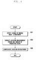
- FIGs. 4 and 5 are flowcharts illustrating a location measurement and a measurement compensation method according to an embodiment of the present invention.
- the location measurement method includes detecting a change of a mobile node's movement pattern, in step 401, correcting a location measurement period ( ⁇ t ) and a weight of a predictive filter depending on the degree of the change of the mobile node's movement pattern, in step 403, and calculating the location of the mobile node based on the corrected location measurement period ( ⁇ t ) and weight of the predictive filter, in step 405.
- the location measurement period ( ⁇ t ) is a duration for measuring the location of the mobile node. The steps of FIG. 4 are described in more detail with reference to FIG. 5 .
- the mobile node estimates its location using the least square method, in step 501.
- the mobile node can convert the displacement information to cylindrical coordinates at every location change measurement period ( ⁇ s ), which is variable.
- the current location of the mobile node i.e., the location recognition coordinates ( x ⁇ , ⁇ )
- the location recognition coordinates ( x ⁇ , ⁇ ) are the measured coordinates of the mobile node.
- the mobile node compares the location recognition coordinate ( x ⁇ , ⁇ ) with the past measured coordinates of the mobile node by location change measurement period ( ⁇ s ), in step 503, and calculates a displacement between the current and past coordinates, in step 505.
- the mobile node converts the displacement to cylindrical coordinates, in step 507.
- the cylindrical coordinate system is a three-dimensional polar coordinate system including a height z (or h) from a plane in addition to a plane polar coordinate system. The coordinate conversion can be performed using Equations (3) to (5).
- the mobile node compares the distance and azimuth of its movement and threshold distance and azimuth values by location change measurement period ( ⁇ s ), respectively, in step 509.
- the mobile node decreases the location measurement period ( ⁇ t ) and corrects the weight of the predictive filter, in step 511, and compensates the location of the mobile node based on the updated location measurement period ( ⁇ t ) and predictive filter's weight, in step 513.
- the mobile node compensates the object(s) (distance and/or azimuth), which is (are) not greater than the corresponding threshold(s), in normal compensation manner, and compensates the object (distance or azimuth), which is greater than the corresponding threshold, by correcting its weight, in step 513.
- FIG. 6 is a diagram illustrating a calculation of a location measurement in a location measurement method according to an embodiment of the present invention.
- reference numbers 610, 620, 630, and 640 denote previous locations ( t -4 ⁇ s , t -3 ⁇ s , t -2 ⁇ s , and t - ⁇ s ) compensated by location change measurement period ( ⁇ s ), and reference number 650 denotes the location measured at time t, i.e., the currently measured location of the mobile node.
- the reference number 660 denotes displacements of the locations 610, 620, 630, and 640 in comparison with the locations before the location change measurement period ( ⁇ s ), and reference number 670 denotes a displacement when the mobile node's movement pattern is changed abruptly. It is shown that the azimuth caused by the change of progressing direction of the mode is large.
- FIG. 7 is a graph illustrating a simulation result of the location measurement method according to an embodiment of the present invention. Particularly, FIG. 7 shows the location measurement simulation result using the least square estimation the Kalman filter which increases the weight of the value measured at a location at which the change of mobile node's movement is large (670 at FIG. 6 ).
- the route tracked by using the location measurement method according to the embodiment of the present invention is nearly identical with the actual route of the mobile node, resulting in improvement of location measurement accuracy.
- the measurement values at locations 700 have been calculated by adopting the corrected covariance matrix which acts as the weight of the Kalman filter, and this has resulted in 70% reduction of RMSE (KalmanFilter) in comparison with that of the conventional method of FIG. 1 .
- the simulation has been performed using Matlap.
- the Matlap is engineering software providing numerical analysis and programming environments and allows easy matrix manipulation, plotting functions and data, implementation algorithms, creation of user interfaces, and interfacing with programs in other languages.
- the location measurement method using a predictive filter adjusts the weight used in the predictive filter and location measurement period ( ⁇ t ) adaptive to the mobile node's movement change, thereby improving the accuracy of location measurement.
- the location measurement method of the present invention improves the error compensation performance of the predictive filter by about 70% in comparison with the conventional error compensation method. Furthermore, the location measurement method of the present invention improves the error compensation performance of the mobile node without compromising system implementation complexity, because the location measurement method may be implemented without any additional devices.
Abstract
Description
- The present invention relates generally to a location measurement method and, in particular, to a location measurement method of a mobile node using a predictive filter that is capable of improving the location measurement accuracy of the mobile node.
- In a method for calculating location measurement error of a mobile node, a predictive filter is used to predict its location using the past measurement information and environmental information.
- In order to compensate location measurement error of a mobile node, a predictive filter based compensation method using past measurements and environmental information, or a finger printing method using previously recorded site-specific signal patterns are used.
- The predictive filter allows estimation of a current location of the mobile node using the past location and state information and compensates for the offset between the measured and predicted locations by adopting weights depending on the reliability of the information. A Kalman filter is one of the well known predictive filters. The Kalman filter adjusts a weight applied to a estimated value of a covariance matrix and an actually measured value.
- The Kalman filter-based location prediction method is briefly explained as follows. First, a mobile node acquires coordinates of at least three anchor nodes and measures periodically the distances from the anchor nodes and then determines coordinates that have the smallest errors from each anchor node through a least square method as the location of the mobile node. The acquired coordinates are input to the Kalman filter so as to be output as a compensated coordinates. This method is described in more detail as follows, with reference to
FIGs. 1 ,2A, and 2B . -
FIG. 1 is a graph illustrating a simulated result of measurement error compensation using a conventional least square method and Kalman filter, andFIGs. 2a and 2b are conceptual diagrams illustrating examples of movements of a mobile node in indoor environments. - In
FIG. 1 , the axes x and y denote distances in units of meters (m). The measurement period (Δt) is set to 2 seconds, and the mobile node moves at a speed of 0.6m/s. - The
solid line 110 denotes the movement line of the mobile node, and mark x 130 denotes a location value estimated by using the least square method, the boldsolid line 150 denotes a movement line of the mobile node compensated for the location measurement errors using the Kalman filter. - Here, it is assumed that the weight of the Kalman filter, i.e. process covariance matrix, and the measurement covariance matrix are constant.
- RMSE (LeastSquare) is a Root Mean Squared Error (RMSE) obtained by applying the least square method. That is, the RMSE indicates the amount of mean error between the coordinates calculated by the least square method and the measured coordinates. RMSE (KalmanFilter) is the RMSE obtained by applying the Kalman filter. That is, the RMSE (KalmanFilter) indicates the size of a mean error between the coordinates obtained by applying the least square method and then the Kalman filter and the measured coordinates.
- As shown in
FIG. 1 , when a constant covariance is used and the movement direction of the mobile node changes abruptly, the route obtained by applying the Kalman filter deviates from the actual movement route. This effect can occur when a movement direction of a mobile node previously moving straight along a corridor changes its movement direction at a corner of the corridor (seeFIG. 2a ), or when the mobile node enters a room positioned at one side of the corridor (seeFIG. 2b ). - In order to solve this problem, research has been focused on searching for ways to determine the weight of the predictive filter, adaptive to the situation of the mobile node. As a result, the most of the conventional techniques have been developed with a supplementary device such as an acceleration sensor and/or an initia sensor for acquiring information required for adjusting the weight of the predictive filter.
- However, the conventional techniques are disadvantageous since additional physical elements, such as the acceleration sensor and initia sensor, increase the manufacturing cost and size of the mobile node. Furthermore, processing the information acquired by the additional elements increases the system complexity.
- In order to solve the above problems of the prior art, the present invention provides a location measurement method that is capable of improving location measurement accuracy using a predictive filter.
- The present invention further provides a location measurement method that is capable of adjusting a parameter of a Kalman filter adaptively for improving location measurement accuracy especially in indoor environment.
- The present invention further provides a location measurement method that is capable of improving the location measurement accuracy of a mobile node by adaptively using a Kalman filter.
- The present invention further provides a location measurement method for a mobile node that is capable of changing a location measurement period (Δt) and weight of a predictive filter adaptive to the movement of the mobile node.
- Furthermore, the present invention provides a location measurement method for a mobile node that is capable of improving location measurement accuracy by predicting a change of the mobile node's movement and correcting the weight of a predictive filter used in a measurement period and error compensation process adaptively.
- In accordance with an embodiment of the present invention, a location measurement method of a mobile node includes detecting change of a movement pattern of the mobile node, correcting weights of a location measurement period and a predictive filter according to the change of movement pattern, and calculating a location of the mobile node using the corrected weights of the location measurement period and predictive filter.
- In accordance with another embodiment of the present invention, a location measurement method of a mobile node includes estimating, when detecting a change of a movement pattern of the mobile node, a location of the mobile node using a least square method, comparing a distance and an azimuth of the movement pattern with respective threshold values, correcting, when the distance of the movement pattern is greater than the threshold values, a weight of a location measurement period, correcting, when the azimuth of the movement pattern is greater than the threshold values, a weight of a predictive filter, and calculating a location measurement of the mobile node by applying the corrected weights.
- The above and other objects, features and advantages of the present invention will be more apparent from the following detailed description in conjunction with the accompanying drawings, in which:
-
FIG. 1 is a graph illustrating a simulation result of location measurement error compensation using a conventional least square method and Kalman filter; -
FIGs. 2a and 2b are conceptual diagrams illustrating movements of a mobile node in indoor environments; -
FIG. 3 is a diagram illustrating concepts of a location measurement period (Δt) and a location change measurement period ( Δs ) for use in a location measurement method according to an embodiment of the present invention; -
FIGs. 4 and5 are flowchart illustrating a location measurement and measurement compensation method according to an embodiment of the present invention -
FIG. 4 is a flowchart illustrating a location measurement method according to an embodiment of the present invention; -
FIG. 5 is a flowchart illustrating a location measurement method according to another embodiment of the present invention; -
FIG. 6 is a diagram illustrating a calculation of a location measurement in a location measurement method according to an embodiment of the present invention; and -
FIG. 7 is a graph illustrating a simulation result of the location measurement method according to an embodiment of the present invention. - Embodiments of the present invention are described with reference to the accompanying drawings in detail. The same reference numbers are used throughout the drawings to refer to the same or like parts. Detailed descriptions of well-known functions and structures incorporated herein may be omitted to avoid obscuring the subject matter of the present invention.
- The words and terms used in the specification and claims are for illustrative purposes only rather than limitation. Examples and constitutions as described herein do not cover all the technical spirit of the present invention but are merely the most preferred embodiments of the present invention. Thus, it should be understood that various equivalents and modifications can be made to the embodiments of the present invention.
- In the following descriptions, a predictive filter-based location measurement method for improving the location measurement accuracy of a mobile node is provided. In the following embodiments, the mobile node adjusts the parameter value of a predictive filer adaptively for enhancing the location measurement accuracy especially in an indoor environment. That is, the mobile node corrects the measurement period (Δt) and weight of the predictive filter adaptive to the movement of the mobile node.
- For this purpose, the mobile node according to an embodiment recognizes a change of a movement pattern and corrects the measurement period (Δt) and weight of the predictive filter adaptive to the change of movement pattern for compensating the location measurement of the mobile node.
- In the location measurement method according to an embodiment of the present invention, the mobile node converts displacement information to cylindrical coordinates every measurement period in order to recognize the change of movement.
- In the location measurement method according to an embodiment of the present invention, the location measurement period ( Δt ) is adjusted in order to compensate the error caused by the change of the mobile node's movement.
- In the location measurement method according to an embodiment of the present invention, the location measurement period ( Δt ) is adjusted inversely proportional to the movement speed of the mobile node.
- In the location measurement method according to an embodiment of the present invention, the weight of the predictive filter is adjusted according to the change of movement of the mobile node.
- In the location measurement method according to an embodiment of the present invention, the mobile node calculates the changes of its movement direction and speed and, when the calculated values are greater than threshold values, the mobile node adjusts weights to be applied between the estimated value of the predictive filter and measured value.
- In the location measurement method according to an embodiment of the present invention, the mobile node increases the weight to be applied to the measured value when the changes of movement direction and speed are greater than the threshold values, such that the measured value is first compensated in a measured location compensation process.
- Although a Kalman filter is adopted in the location measurement method according to an embodiment of the present invention as the predictive filter, the present invention is not limited thereto. For example, the location measurement method of the present invention can be implemented with various predictive filters for calculating the location measurement error.
- The Kalman filter is called an optimal recursive data processing algorithm. The Kalman filter tracks an optimal value through a recursive data processing and is a recursive computational solution effective for tracking a time-dependent state vector according to the time having equations of motion to a noise in real time using the least square method. Here, the least square method is a method for obtaining an estimated amount that minimizes the sum of square of an error, i.e., the least square estimator.
- Usage of the Kalman filter is described as follows.
- First, it is assumed that x(n) and y(n) satisfy a set of Equations (1):

- In Equations (1), ignoring noise, the variables are expected vary over time due to their linear relationships. Also, ignoring the expected noise between the variables and the observed values, linear relationships are therebetween.
- In Equations (1), x(n) is an Mx1 matrix containing a variable expected to be known at specific time n. As shown in the first equation, ignoring the noise v 1(n), x(n) varies to x(n+1) linearly by the matrix F(n+1,n). F(n+1,n) defining the relationship between x(n) and x(n+1) is an MxM matrix called transition matrix. v 1(n) is noise or observation error and follows a normal distribution with a mean of 0 (Mx1 zero matrix) and a covariance matrix Q 1(n) (MxM matrix) as shown in the third equation. y(n) is an Nx1 matrix containing the values observed for knowing the x(n).
- As shown in the second equation, ignoring the noise v 2(n), y(n) has a linear relationship with x(n) by the matrix C(n). C(n) defines the relationship between y(n) and x(n) is an NxM matrix called a measurement matrix. v 2(n) can be regarded as noise or an observation error and follows a normal distribution with a mean of 0 (Nx1 zero matrix) and a covariance matrix Q2 (n) (NxN matrix).
- With the above system model, the Kalman filter is used to estimate x(n) as follows:
-
- x(1|Y(0)) => x(1) expected as optimal value (Mx1 matrix)
- K(1,0) => constant value for optimal performance (MxM matrix)
- F(n,n+1)=F(n+1,n)-1 => pre-calculate if a model is determined (MxM matrix)
-


- where Y(n) is a set of observed values {y(1),y(2),...,y(n)}, x(n|Y(n-1) is x(n) estimated based on the observation results to Y(n-1), F(n,n+1) is an expanded concept of F(n+1,n), i.e., an inverse matrix of F(n+1,n) for obtaining x(n) from x(n+1) when ignoring noise, and other parameters are variables used in the intermediate calculation process. The superscript H denotes a conjugate transpose of a matrix, and superscript -1 denotes an inverse matrix of a matrix.
- The parameters used in the embodiments of the present invention are defined hereinafter.
- According to embodiments of the present invention, the location measurement period (Δt) is an interval for measuring the location of a mobile node. The mobile node measures the distances from at least three anchor nodes and calculates its location based on the distances every measurement period (Δt).
- Also, a location change measurement period (Δs) is used for measuring a movement change of the mobile node according to embodiments of the present invention. The mobile node compares the coordinates of a past change measurement period with the coordinates of the current change measurement period, i.e., the location change measurement period (Δs) is a parameter for determining a duration for comparing the past coordinates and current coordinates and is a constant multiple of the location measurement period (Δt).
- The location change measurement period ( Δs ) is set to a constant multiple of the location measurement period (Δt) in order to secure at least one set of coordinates from previous measurements.
- The location change measurement period ( Δs ) is variable. In order to detect the movement of the mobile node more precisely, it is preferable to set the location change measurement period ( Δs ) to a large value. Otherwise, in order to detect the movement of the mobile node more quickly, it is preferable to set the location change measurement period (Δs) to a small value. When the location change measurement period (Δs) is too short, it is difficult to determine whether the angular change is caused by the actual movement or an error. Accordingly, the location change measurement period ( Δs ) should be set to a value obtained for an optimized system performance.
- The location measurement method according to an embodiment of the present invention is described in more detail with reference to drawings.
-
FIG. 3 is a diagram illustrating concepts of a location measurement period (Δt) and a location change measurement period ( Δs ) for use in a location measurement method according to an embodiment of the present invention. InFIG. 3 , it is shown that a maximum error angle of the mobile node having a predetermined error range is determined according to the location change measurement period (Δs). -
Reference number 310 denotes an actual movement route of the mobile node, 320 denotes a location change measurement period (Δs), and 330 denotes a location measurement period ( Δt ).Reference numbers route 310, andreference numbers locations Reference number 360 denotes an error range. - Adjustment of the measurement periods and the weight of the predictive filter for calculating the measured locations is described as follows.
- The mobile node acquires ranging results from at least three anchor nodes every location measurement period (Δt) and calculates the location recognition coordinates (x̃,ỹ) of the mobile node using the least square estimation. The location recognition coordinates (x̃,ỹ) are measured location coordinates.
- The reason the ranging results are acquired from at least three anchor nodes is to calculate the position of the mobile node using a triangulation method. The triangulation method calculates the distances between the mobile node and the anchor nodes using the time-of-arrivals of signals from the anchor nodes. The location is determined at a point at which the circles drawn with the distances from the at least three anchor nodes as their radii are crossing. For this purpose, the mobile node receives the ranging results from at least three anchor nodes.
- Next, the mobile node compares the location recognition coordinates (x̃,ỹ) acquired from the least square estimations with past coordinates compensated before the location change measurement period (Δs) and converts the displacements to the coordinates of a cylindrical coordinate system (σ,φ,z).
- The cylindrical coordinate system is a three-dimensional polar coordinate system in which a point P is represented by a triple (σ,φ,z) including a height z (or h) from a plane in addition to a plane polar coordinate system. The cylindrical coordinate system is useful in analyzing surfaces that are symmetrical about an axis. In the case of the cylindrical coordinate system, a point can be represented by multiple coordinates. Accordingly, as a generalization, the ranges of parameters are restricted as follows.

- In the ranges of the parameters, the coordinates of the rectangular coordinate system is converted to the coordinates of the cylindrical coordinate system as follows:

- The coordinate conversion Equations (4) can be expressed by Equations (5) to be applied to the location measurement method according to an embodiment of the present invention. The location recognition coordinates (x̃,ỹ) acquired from the least square estimations can be converted to the cylindrical coordinates as follows:

and
- The location recognition coordinates (x̃,ỹ) measured at time t are compared with a past location measurement calculated before the location change measurement period (Δs) to be converted to cylindrical coordinates according to the Equations (5). In a cylindrical coordinate system, σ t is a mobile node's movement distance, and φ t is a mobile node's movement azimuth (angle).
- Next, the mobile node compares the distance σ t and azimuth φ t of the movement during the location change measurement period ( Δs ) with respective threshold values.
- The threshold values are preferably set larger than error range of the location measurement. Accordingly, in a case that the location measurement error range is narrow, the thresholds are set to much smaller values, thereby detecting the movement pattern of the mobile node mover sensitively.
- As a result of the comparison between the measurements with the threshold values, if the measured distance is greater than the threshold distance, the mobile node decreases the location measurement period (Δt). Also, if the measured azimuth is greater than the threshold azimuth, the mobile node weights the location recognition coordinates (x̃,ỹ) rather than the estimated coordinates in calculating the location measurement by adjusting the weight of the predictive filter.
- Otherwise, if the measured distance and azimuth of the mobile node's movement are less than the threshold values, the mobile node compensates the measurements using the predictive filter in conventional manner.
- The location measurement method based on the above-described system is described hereinafter. The present invention is not limited to the following description, but can be practiced with various equivalents and modifications in other embodiments.
-
FIGs. 4 and5 are flowcharts illustrating a location measurement and a measurement compensation method according to an embodiment of the present invention. - Referring to
FIG. 4 , the location measurement method according to an embodiment of the present invention includes detecting a change of a mobile node's movement pattern, instep 401, correcting a location measurement period (Δt) and a weight of a predictive filter depending on the degree of the change of the mobile node's movement pattern, instep 403, and calculating the location of the mobile node based on the corrected location measurement period ( Δt ) and weight of the predictive filter, instep 405. - The location measurement period (Δt) is a duration for measuring the location of the mobile node. The steps of
FIG. 4 are described in more detail with reference toFIG. 5 . - Referring to
FIGs. 4 and5 , if the change of movement pattern is detected, the mobile node estimates its location using the least square method, instep 501. - In order to recognize the change of the movement pattern, the mobile node can convert the displacement information to cylindrical coordinates at every location change measurement period (Δs), which is variable. The current location of the mobile node, i.e., the location recognition coordinates (x̃,ỹ), is estimated by applying the least square method to the ranging results received from at least three anchor nodes. Here, the location recognition coordinates (x̃,ỹ) are the measured coordinates of the mobile node.
- Next, the mobile node compares the location recognition coordinate (x̃,ỹ) with the past measured coordinates of the mobile node by location change measurement period (Δs), in
step 503, and calculates a displacement between the current and past coordinates, instep 505. Next, the mobile node converts the displacement to cylindrical coordinates, instep 507. The cylindrical coordinate system is a three-dimensional polar coordinate system including a height z (or h) from a plane in addition to a plane polar coordinate system. The coordinate conversion can be performed using Equations (3) to (5). - Next, the mobile node compares the distance and azimuth of its movement and threshold distance and azimuth values by location change measurement period (Δs), respectively, in
step 509. - As a result of the comparison, if both the distance and azimuth of the mobile node's movement are greater than the threshold distance and azimuth values, then the mobile node decreases the location measurement period (Δt) and corrects the weight of the predictive filter, in
step 511, and compensates the location of the mobile node based on the updated location measurement period ( Δt ) and predictive filter's weight, in step 513.Otherwise, if at least one of the distance and azimuth of the mobile node's movement is less than or equal to than the threshold distance value or azimuth value, the mobile node compensates the object(s) (distance and/or azimuth), which is (are) not greater than the corresponding threshold(s), in normal compensation manner, and compensates the object (distance or azimuth), which is greater than the corresponding threshold, by correcting its weight, instep 513. -
FIG. 6 is a diagram illustrating a calculation of a location measurement in a location measurement method according to an embodiment of the present invention. - Referring to
FIG. 6 ,reference numbers reference number 650 denotes the location measured at time t, i.e., the currently measured location of the mobile node. Thereference number 660 denotes displacements of thelocations reference number 670 denotes a displacement when the mobile node's movement pattern is changed abruptly. It is shown that the azimuth caused by the change of progressing direction of the mode is large. - The results of simulation performed for such example situation is shown in
FIG. 7 . -
FIG. 7 is a graph illustrating a simulation result of the location measurement method according to an embodiment of the present invention. Particularly,FIG. 7 shows the location measurement simulation result using the least square estimation the Kalman filter which increases the weight of the value measured at a location at which the change of mobile node's movement is large (670 atFIG. 6 ). - As shown in
FIG. 7 , in comparison with the simulation result of the conventional method inFIG. 1 , the route tracked by using the location measurement method according to the embodiment of the present invention is nearly identical with the actual route of the mobile node, resulting in improvement of location measurement accuracy. - The measurement values at
locations 700 have been calculated by adopting the corrected covariance matrix which acts as the weight of the Kalman filter, and this has resulted in 70% reduction of RMSE (KalmanFilter) in comparison with that of the conventional method ofFIG. 1 . - The simulation has been performed using Matlap. The Matlap is engineering software providing numerical analysis and programming environments and allows easy matrix manipulation, plotting functions and data, implementation algorithms, creation of user interfaces, and interfacing with programs in other languages.
- Although embodiments of the present invention are described in detail hereinabove, it should be clearly understood that many variations and/or modifications of the basic inventive concepts herein taught which may appear to those skilled in the present art will still fall within the spirit and scope of the present invention, as defined in the appended claims.
- As described above, the location measurement method using a predictive filter according to the present invention adjusts the weight used in the predictive filter and location measurement period ( Δt ) adaptive to the mobile node's movement change, thereby improving the accuracy of location measurement.
- Also, the location measurement method of the present invention improves the error compensation performance of the predictive filter by about 70% in comparison with the conventional error compensation method. Furthermore, the location measurement method of the present invention improves the error compensation performance of the mobile node without compromising system implementation complexity, because the location measurement method may be implemented without any additional devices.
Claims (14)
- A location measurement method of a mobile node, comprising:detecting a change of a movement pattern of the mobile node;correcting weights of a location measurement period and a predictive filter according to the change of movement pattern; andcalculating a current location of the mobile node using values updated by the corrected weights.
- The location measurement method of claim 1, wherein detecting the change of the movement pattern of the mobile node comprises converting displacement information during a location change measurement period to cylindrical coordinates,
and wherein the location change measurement period is variable. - The location measurement method of claim 1, wherein the weights comprise at least one parameter that is applied to the location measurement period and the predictive filter for calculating the location measurement error caused by the change of movement pattern of the mobile node.
- The location measurement method of claim 3, wherein the location measurement period is inversely proportional to a movement speed of the mobile node.
- The location measurement method of claim 1, wherein correcting the weights of the location measurement period and the predictive filter comprises:calculating displacements of a movement direction and a distance of the mobile node at every location measurement period;comparing the calculated displacements with predetermined threshold values; andadjusting, when the displacements are greater than respective threshold values of the predetermined threshold values, the weights to be applied to estimation values of the predictive filter.
- The location measurement method of claim 5, wherein correcting the weights of the location measurement period and the predictive filter comprises calculating, when the displacements are less than or equal to the respective threshold values, the location measurement error by applying the adjusted weights.
- A location measurement method of a mobile node, comprising:estimating, when detecting a change of a movement pattern of the mobile node, a location of the mobile node using a least square method;comparing a distance and an azimuth of the movement pattern with respective threshold values;correcting, when the distance of the movement pattern is greater than the threshold values, a weight of a location measurement period;correcting, when the azimuth of the movement pattern is greater than the threshold values, a weight of a predictive filter; andcalculating a location measurement of the mobile node by applying the corrected weights.
- The location measurement method of claim 7, wherein estimating the location comprises converting displacement information to cylindrical coordinates according to a location change measurement period in order to detect the change of movement pattern of the mobile node,
and wherein the location change measurement period being variable. - The location measurement method of claim 7, wherein converting the displacement information to the cylindrical coordinates comprises:calculating a displacement between the estimated location and previous location before the location change measurement period;converting the displacement to the cylindrical coordinates; andacquiring the distance and the azimuth of the movement pattern from the cylindrical coordinates.
- The location measurement method of claim 7, wherein calculating the location measurement comprises:calculating, when at least one of the distance and azimuth of the movement pattern is less than or equal to the respective threshold values, the at least one of the distance and the azimuth using the predictive filter; andcorrecting, when at least one of the distance and the azimuth of the movement pattern is greater than the respective threshold values, the weight of the at least one of the distance and azimuth.
- The location measurement method of claim 9, wherein the distance and the azimuth are obtained by calculating a displacement between location recognition coordinates (x̃,ỹ) measured at a time (t) and the coordinates measured and compensated before a location change measurement period (Δs) and converting the displacement to cylindrical coordinates using:

and
where σ t is the distance of the mobile node's movement, and φ t is the azimuth (angle) of the mobile node's movement. - The location measurement method of claim 11, wherein location recognition coordinates (x̃,ỹ) are coordinates of the mobile node that are measured currently, and the location change measurement period (Δs) is a unit duration for measuring change of mobile node's movement.
- The location measurement method of claim 7, wherein the threshold values correspond to measurement error ranges of the mobile node.
- The location measurement method of claim 7, wherein the predictive filter is a Kalman filter.
Applications Claiming Priority (1)
| Application Number | Priority Date | Filing Date | Title |
|---|---|---|---|
| KR1020080019931A KR101005753B1 (en) | 2008-03-04 | 2008-03-04 | Location measurement method based on predictive filter |
Publications (2)
| Publication Number | Publication Date |
|---|---|
| EP2098882A2 true EP2098882A2 (en) | 2009-09-09 |
| EP2098882A3 EP2098882A3 (en) | 2010-05-05 |
Family
ID=40821736
Family Applications (1)
| Application Number | Title | Priority Date | Filing Date |
|---|---|---|---|
| EP09153873A Ceased EP2098882A3 (en) | 2008-03-04 | 2009-02-27 | Location measurement method based on predictive filter |
Country Status (4)
| Country | Link |
|---|---|
| US (1) | US8374624B2 (en) |
| EP (1) | EP2098882A3 (en) |
| KR (1) | KR101005753B1 (en) |
| CN (1) | CN101526602B (en) |
Families Citing this family (25)
| Publication number | Priority date | Publication date | Assignee | Title |
|---|---|---|---|---|
| KR100978060B1 (en) * | 2009-12-08 | 2010-08-25 | 주식회사 케이티 | Method for position adjustment in indoor position determination system |
| US20110177809A1 (en) * | 2010-01-15 | 2011-07-21 | Qualcomm Incorporated | Affecting a navigation function in response to a perceived transition from one environment to another |
| US8504077B2 (en) * | 2010-12-04 | 2013-08-06 | Wavemarket, Inc. | System and method for monitoring and disseminating mobile device location information |
| KR101140045B1 (en) * | 2010-12-23 | 2012-05-02 | 연세대학교 산학협력단 | Method and apparatus for tracking user location |
| US9295030B2 (en) | 2011-12-02 | 2016-03-22 | Qualcomm Incorporated | Methods and apparatuses for improved paging area identifier selection in wireless networks containing low power base stations |
| US20130196681A1 (en) * | 2012-01-31 | 2013-08-01 | Qualcomm Incorporated | Compensating for user occlusion in wi-fi positioning using mobile device orientation |
| US9113298B2 (en) | 2012-06-12 | 2015-08-18 | Telecommunication Systems, Inc. | Geofence with kalman filter |
| GB201213172D0 (en) * | 2012-07-24 | 2012-09-05 | Sensewhere Ltd | Method of estimating position of a device |
| KR20140052110A (en) * | 2012-10-11 | 2014-05-07 | 한국전자통신연구원 | Apparatus and method for estimating a network maximum delay, apparatus and method for controlling a network admission |
| EP2984882A4 (en) | 2013-04-12 | 2016-11-09 | Hewlett Packard Entpr Dev Lp | Location determination of a mobile device |
| US9686765B2 (en) | 2013-04-12 | 2017-06-20 | Hewlett Packard Enterprise Development Lp | Determining an angle of direct path of a signal |
| US8768618B1 (en) * | 2013-05-15 | 2014-07-01 | Google Inc. | Determining a location of a mobile device using a multi-modal kalman filter |
| KR102280610B1 (en) * | 2014-04-24 | 2021-07-23 | 삼성전자주식회사 | Method and apparatus for location estimation of electronic device |
| ES2762953T3 (en) | 2014-05-15 | 2020-05-26 | Samsung Electronics Co Ltd | System to provide personalized information and procedure to provide personalized information |
| WO2015174764A1 (en) | 2014-05-15 | 2015-11-19 | Samsung Electronics Co., Ltd. | System for providing personalized information and method of providing the personalized information |
| KR102322027B1 (en) * | 2014-05-15 | 2021-11-08 | 삼성전자주식회사 | System for providing personalization information and device thereof |
| US9646418B1 (en) | 2014-06-10 | 2017-05-09 | Ripple Inc | Biasing a rendering location of an augmented reality object |
| US9619940B1 (en) * | 2014-06-10 | 2017-04-11 | Ripple Inc | Spatial filtering trace location |
| US10026226B1 (en) | 2014-06-10 | 2018-07-17 | Ripple Inc | Rendering an augmented reality object |
| US10930038B2 (en) | 2014-06-10 | 2021-02-23 | Lab Of Misfits Ar, Inc. | Dynamic location based digital element |
| GB201414975D0 (en) * | 2014-08-22 | 2014-10-08 | Bevan Heba | Sensor systems |
| US9993723B2 (en) * | 2014-09-25 | 2018-06-12 | Intel Corporation | Techniques for low power monitoring of sports game play |
| US10324162B2 (en) * | 2015-02-18 | 2019-06-18 | Sony Corporation | Determining the geographic location of a mobile communications device using a positioning reference signal |
| KR20230084879A (en) * | 2021-12-06 | 2023-06-13 | (주)뉴빌리티 | Multiple positioning method and apparatus |
| CN115267667B (en) * | 2022-09-28 | 2023-04-07 | 长沙迪迈数码科技股份有限公司 | Underground high-precision positioning correction method, device, equipment and storage medium |
Citations (2)
| Publication number | Priority date | Publication date | Assignee | Title |
|---|---|---|---|---|
| US6385454B1 (en) | 1998-10-09 | 2002-05-07 | Microsoft Corporation | Apparatus and method for management of resources in cellular networks |
| US20060002837A1 (en) | 2002-05-24 | 2006-01-05 | Moerck Rudi E | Processes for making rare earth metal oxycarbonates |
Family Cites Families (8)
| Publication number | Priority date | Publication date | Assignee | Title |
|---|---|---|---|---|
| JPS5412011A (en) * | 1977-06-30 | 1979-01-29 | Nissan Motor Co Ltd | Intake-air amount detecting apparatus for internal combustion engine |
| US6732050B2 (en) * | 2001-05-23 | 2004-05-04 | Nokia Mobile Phones Ltd | Two-stage interacting multiple models filter for use in a global positioning system |
| EP1602202A4 (en) * | 2003-03-13 | 2007-05-23 | Meshnetworks Inc | A real -time system and method for improving the accuracy of the computed location of mobile subscribers in a wireless ad-hoc network using a low speed central processing unit |
| WO2005062066A2 (en) * | 2003-10-22 | 2005-07-07 | Awarepoint Corporation | Wireless position location and tracking system |
| US7158882B2 (en) * | 2004-03-01 | 2007-01-02 | Global Locate, Inc | Method and apparatus for locating position of a mobile receiver |
| US7012564B2 (en) * | 2004-08-05 | 2006-03-14 | Global Locate, Inc. | Method and apparatus for adjusting a measurement cycle in a satellite positioning system signal receiver |
| US7761233B2 (en) * | 2006-06-30 | 2010-07-20 | International Business Machines Corporation | Apparatus and method for measuring the accurate position of moving objects in an indoor environment |
| CN100507600C (en) * | 2006-12-01 | 2009-07-01 | 清华大学 | Indoor precision orientation method of following multi-moving target |
-
2008
- 2008-03-04 KR KR1020080019931A patent/KR101005753B1/en active IP Right Grant
-
2009
- 2009-02-27 EP EP09153873A patent/EP2098882A3/en not_active Ceased
- 2009-03-04 US US12/397,799 patent/US8374624B2/en active Active
- 2009-03-04 CN CN2009101185625A patent/CN101526602B/en active Active
Patent Citations (2)
| Publication number | Priority date | Publication date | Assignee | Title |
|---|---|---|---|---|
| US6385454B1 (en) | 1998-10-09 | 2002-05-07 | Microsoft Corporation | Apparatus and method for management of resources in cellular networks |
| US20060002837A1 (en) | 2002-05-24 | 2006-01-05 | Moerck Rudi E | Processes for making rare earth metal oxycarbonates |
Non-Patent Citations (2)
| Title |
|---|
| CONGWEI HU ET AL.: "Adaptive Kalman filtering for vehicle navigation", JOURNAL OF GLOBAL POSITIONING SYSTEMS, vol. 2, no. 1, 1 January 2003 (2003-01-01), pages 42 - 47, XP007912326 |
| PROMKAJIN N. ET AL.: "An improvement to the adaptive Kalman filter with the feedback of estimation error", STUDENT CONFERENCE ON RESEARCH AND DEVELOPMENT (SCORED), 2003 PROCEEDINGS, PUTRAJAYA, MALAYSIA, 25-26 AUG 2003, 25 August 2003 (2003-08-25), pages 23 - 28, XP010812256, DOI: doi:10.1109/SCORED.2003.1459657 |
Also Published As
| Publication number | Publication date |
|---|---|
| KR20090094929A (en) | 2009-09-09 |
| CN101526602B (en) | 2013-04-24 |
| US8374624B2 (en) | 2013-02-12 |
| US20090227266A1 (en) | 2009-09-10 |
| CN101526602A (en) | 2009-09-09 |
| EP2098882A3 (en) | 2010-05-05 |
| KR101005753B1 (en) | 2011-01-06 |
Similar Documents
| Publication | Publication Date | Title |
|---|---|---|
| EP2098882A2 (en) | Location measurement method based on predictive filter | |
| CN113074739B (en) | UWB/INS fusion positioning method based on dynamic robust volume Kalman | |
| CN108319570B (en) | Asynchronous multi-sensor space-time deviation joint estimation and compensation method and device | |
| CN104330083A (en) | Multi-robot cooperative positioning algorithm based on square root unscented kalman filter | |
| KR101628154B1 (en) | Multiple target tracking method using received signal strengths | |
| CN107941212B (en) | Vision and inertia combined positioning method | |
| Ibrahim et al. | Inertial measurement unit based indoor localization for construction applications | |
| KR100977246B1 (en) | Apparatus and method for estmating positon using forward link angle of arrival | |
| KR101390776B1 (en) | Localization device, method and robot using fuzzy extended kalman filter algorithm | |
| CN112180361A (en) | Vehicle-mounted radar target tracking method based on dynamic federal filtering | |
| KR101833007B1 (en) | Method and system for estimating position and velocity of underwater vehicle using doppler beacon | |
| KR101180825B1 (en) | Apparatus and Method for tracing location of the Mobile based on Sensor Network | |
| JP5402751B2 (en) | Sensor network, state estimation method and program | |
| KR101462007B1 (en) | Apparatus for estimating attitude and method for estimating attitude | |
| CN107966697B (en) | Moving target tracking method based on progressive unscented Kalman | |
| CN115540854A (en) | Active positioning method, equipment and medium based on UWB assistance | |
| CN114705223A (en) | Inertial navigation error compensation method and system for multiple mobile intelligent bodies in target tracking | |
| CN114339595A (en) | Ultra-wideband dynamic inversion positioning method based on multi-model prediction | |
| Cho et al. | Localization for a mobile node based on chrip spread spectrum ranging | |
| CN112285697A (en) | Multi-sensor multi-target space-time deviation calibration and fusion method | |
| CN111123323A (en) | Method for improving positioning precision of portable equipment | |
| Beutler et al. | Optimal stochastic linearization for range-based localization | |
| JP3440010B2 (en) | Target tracking device | |
| CN113324563B (en) | Self-adaptive sensor management method for multi-sensor multi-target tracking | |
| Sivaraman et al. | Adaptive Polynomial Predictive Filter: Solving Inconsistent and Interrupted Sensor Data Challenges |
Legal Events
| Date | Code | Title | Description |
|---|---|---|---|
| PUAI | Public reference made under article 153(3) epc to a published international application that has entered the european phase |
Free format text: ORIGINAL CODE: 0009012 |
|
| 17P | Request for examination filed |
Effective date: 20090227 |
|
| AK | Designated contracting states |
Kind code of ref document: A2 Designated state(s): AT BE BG CH CY CZ DE DK EE ES FI FR GB GR HR HU IE IS IT LI LT LU LV MC MK MT NL NO PL PT RO SE SI SK TR |
|
| AX | Request for extension of the european patent |
Extension state: AL BA RS |
|
| PUAL | Search report despatched |
Free format text: ORIGINAL CODE: 0009013 |
|
| AK | Designated contracting states |
Kind code of ref document: A3 Designated state(s): AT BE BG CH CY CZ DE DK EE ES FI FR GB GR HR HU IE IS IT LI LT LU LV MC MK MT NL NO PL PT RO SE SI SK TR |
|
| AX | Request for extension of the european patent |
Extension state: AL BA RS |
|
| RAP1 | Party data changed (applicant data changed or rights of an application transferred) |
Owner name: SAMSUNG ELECTRONICS CO., LTD. Owner name: KOREA ADVANCED INSTITUTE OF SCIENCE AND TECHNOLOGY |
|
| 17Q | First examination report despatched |
Effective date: 20101105 |
|
| AKX | Designation fees paid |
Designated state(s): DE GB NL |
|
| R17C | First examination report despatched (corrected) |
Effective date: 20110518 |
|
| RAP1 | Party data changed (applicant data changed or rights of an application transferred) |
Owner name: SAMSUNG ELECTRONICS CO., LTD. Owner name: KOREA ADVANCED INSTITUTE OF SCIENCE AND TECHNOLOGY |
|
| STAA | Information on the status of an ep patent application or granted ep patent |
Free format text: STATUS: THE APPLICATION HAS BEEN REFUSED |
|
| 18R | Application refused |
Effective date: 20171020 |