EP2098925A1 - Method and device for programming and/or configuring a safety controller - Google Patents
Method and device for programming and/or configuring a safety controller Download PDFInfo
- Publication number
- EP2098925A1 EP2098925A1 EP08102395A EP08102395A EP2098925A1 EP 2098925 A1 EP2098925 A1 EP 2098925A1 EP 08102395 A EP08102395 A EP 08102395A EP 08102395 A EP08102395 A EP 08102395A EP 2098925 A1 EP2098925 A1 EP 2098925A1
- Authority
- EP
- European Patent Office
- Prior art keywords
- actuators
- safety controller
- sensors
- properties
- elements
- Prior art date
- Legal status (The legal status is an assumption and is not a legal conclusion. Google has not performed a legal analysis and makes no representation as to the accuracy of the status listed.)
- Withdrawn
Links
Images


Classifications
-
- G—PHYSICS
- G05—CONTROLLING; REGULATING
- G05B—CONTROL OR REGULATING SYSTEMS IN GENERAL; FUNCTIONAL ELEMENTS OF SUCH SYSTEMS; MONITORING OR TESTING ARRANGEMENTS FOR SUCH SYSTEMS OR ELEMENTS
- G05B19/00—Programme-control systems
- G05B19/02—Programme-control systems electric
- G05B19/04—Programme control other than numerical control, i.e. in sequence controllers or logic controllers
- G05B19/042—Programme control other than numerical control, i.e. in sequence controllers or logic controllers using digital processors
- G05B19/0426—Programming the control sequence
-
- G—PHYSICS
- G05—CONTROLLING; REGULATING
- G05B—CONTROL OR REGULATING SYSTEMS IN GENERAL; FUNCTIONAL ELEMENTS OF SUCH SYSTEMS; MONITORING OR TESTING ARRANGEMENTS FOR SUCH SYSTEMS OR ELEMENTS
- G05B2219/00—Program-control systems
- G05B2219/20—Pc systems
- G05B2219/23—Pc programming
- G05B2219/23258—GUI graphical user interface, icon, function bloc editor, labview
-
- G—PHYSICS
- G05—CONTROLLING; REGULATING
- G05B—CONTROL OR REGULATING SYSTEMS IN GENERAL; FUNCTIONAL ELEMENTS OF SUCH SYSTEMS; MONITORING OR TESTING ARRANGEMENTS FOR SUCH SYSTEMS OR ELEMENTS
- G05B2219/00—Program-control systems
- G05B2219/20—Pc systems
- G05B2219/23—Pc programming
- G05B2219/23261—Use control template library
-
- G—PHYSICS
- G05—CONTROLLING; REGULATING
- G05B—CONTROL OR REGULATING SYSTEMS IN GENERAL; FUNCTIONAL ELEMENTS OF SUCH SYSTEMS; MONITORING OR TESTING ARRANGEMENTS FOR SUCH SYSTEMS OR ELEMENTS
- G05B2219/00—Program-control systems
- G05B2219/20—Pc systems
- G05B2219/23—Pc programming
- G05B2219/23293—Automated assembly of machine control software, reusable software components
-
- G—PHYSICS
- G05—CONTROLLING; REGULATING
- G05B—CONTROL OR REGULATING SYSTEMS IN GENERAL; FUNCTIONAL ELEMENTS OF SUCH SYSTEMS; MONITORING OR TESTING ARRANGEMENTS FOR SUCH SYSTEMS OR ELEMENTS
- G05B2219/00—Program-control systems
- G05B2219/20—Pc systems
- G05B2219/23—Pc programming
- G05B2219/23424—Select construction element from function library
Definitions
- the invention relates to a method for programming and / or configuring a safety controller according to the preamble of claim 1 and to an apparatus for carrying out the method according to claim 9.
- safety controllers are used to respond correctly to a specified type when a danger signal is present.
- a typical application of safety technology is to protect dangerous machinery, such as presses or robots, that need to be shut down or secured immediately when operating personnel are approaching inappropriately.
- a sensor is provided which detects the approach, such as a light grid or a security camera. If such a sensor detects a hazard, a safety controller connected to the sensor must generate a shutdown signal in an absolutely reliable manner.
- a graphical user interface for programming programmable logic controllers is known, which makes it possible to select interfaces and parameterize them via windows and selection fields, for example buttons or digital inputs.
- This document is not concerned with safety controls and the specific problems that need to be considered in safety engineering.
- the application of safety controls moves in the complexity created by the number of components between a simple safety switch and a plant control. In contrast to a PLC, fewer components need to be controlled, but on the other hand, they have to be switched with very high safety requirements.
- the document merely describes the parameterization of a fixed number of predetermined components. New components with different parameters or other groupings of parameters can not be created, so expandability and flexibility are compromised.
- the term sensor should be understood in a very broad sense as a general signal generator, which does not necessarily detect events in the environment, but for example as a Switch or a timer outputs signals.
- the controller can be part of the connection module in a compact embodiment, which is then simultaneously control and connection module, but usually a separate control module is provided.
- the control can be central or distributed, both over several modules of the same row of modules and distributed over several rows of modules, which communicate with each other via fieldbus or the like.
- the invention is based on the idea of making the number of available sensors and actuators expandable. In this way, customer-specific and application-specific further elements can be added in the simplest possible way.
- the new elements are based on a selection of properties or proven existing elements so as not to introduce errors into the safety control by the new elements.
- the new element means a name, a symbol, an icon or another representation in the graphical user interface as well as the property definitions stored for this element.
- Each new element forms a class with specific property definitions, value ranges and default settings, ie parameter types .
- the new element represents a sensor or actuator that was previously not selectable.
- a new element thus differs from the existing elements not only by the values of its parameters, but also by the definition of the parameter types or properties per se. If a new element created according to the invention is selected or instantiated in the further course of a configuration or programming, then the defined properties can no longer be modified in accordance with the invention, but merely properties can be assigned to them, specifically as defined by the definition of the properties of the new element Wise.
- a new element may be a three-dimensional stereoscopic camera and one of its property definitions set as the base distance of its two individual cameras. The thus newly created element can then not be selected once or multiple times in any subsequent configuration or programming and thus instantiated, wherein for each such selected three-dimensional stereoscopic camera, a preset basic distance can be adopted or an individual distance value can be set.
- connection modules are selected which provide the required inputs and / or outputs, the sensors and / or actuators assigned to appropriate inputs and / or outputs, set logic rules, according to which sensor signals are offset at the inputs of the safety controller to controls for actuators at the outputs of the safety controller, the resulting configuration by connecting sensors and / or actuators with inputs and / or outputs of Safety control implemented in a system formed by the safety controller and the sensors and / or actuators, and the resulting program is transferred to the central control of the safety controller.
- the additional sensors and actuators represented by the new elements can thus be integrated into a simple, safe and fast method for configuring and programming a safety controller.
- the selected elements are preferably first stored in an intermediate area and then automatically assigned to all sensors and / or actuators represented by the elements stored in the intermediate area by inputs and / or outputs of suitable connection modules by calling an assignment function.
- the mapping function may be limited to a separate selection of elements of the intermediate region.
- Properties which can be set to new elements for later assignment preferably comprise one or more of the following: type designation, in particular order number, name, manufacturer; Number of terminals; Type of connections, in particular digital or analog, single-channel or dual-channel; Type of signal, in particular complementary, opposite or equivalent, electrical quantities such as current, voltage, capacity; Communication protocol, in particular type of signal, input and output delay, discrepancy time; physical characteristics of the connections, in particular wire diameter or plug type; Test options, in particular test signals, test duration, test time, expected expenditure on a test, duration and time of the test.
- These are all characteristics of sensors and actuators that are or may be relevant to safety control tasks, and therefore cover at least a majority of those characteristics or parameter types that might be needed to incorporate a new element for a new sensor or actuator. It is conceivable that a connected sensor or actuator itself brings along its parameter list, that is, transmits the property definitions to the graphical user interface and thereby defines them, thereby creating the possibility for sensors or actuators of its kind to be integrated into the safety controller
- the representation of new elements in the graphical user interface is advantageously editable, in particular name, symbol, arrangement in the display or arrangement in a menu tree. This means that new elements can be integrated into the graphical user interface in a clear, eye-catching way, according to personal preferences or as error-avoidant as possible.
- New elements are preferably based on one or more primitives, whereby the determination of which properties can be assigned to the new elements is made by adopting or selecting from a global or inherited from the primitive catalog.
- the touchdown on existing elements is particularly advantageous if only make minor changes or at least extensive definitions of already available elements can be adopted.
- additional properties can be set, which have none of the basic elements.
- the catalog of possible properties thus comprises a selection of conceivable properties of sensors and actuators which the safety controller can process, and / or the union of those properties which the basic elements possess. Initially, only the characteristics at the inputs and outputs are relevant from the point of view of the safety controller, because this is the connection to the sensors and actuators, but other properties can also be defined via the safety controller and parameterized later.
- Basic elements are both those with which the graphical user interface is delivered, as well as stored or imported elements that have been created according to the invention.
- the selected or inherited properties are more preferably adjusted in the determination by presetting, value ranges, additional setting options and / or reduced setting options for the subsequent selection.
- the properties as explained in more detail, only the framework is specified, ie that an element has the property at all. If a new element is actually selected later, it still has to be parameterized, ie values for the properties must be selected. In order to facilitate this and above all to ensure safety, presettings are offered or value ranges are limited. As far as inherited properties are concerned, it sometimes makes sense to give the new element additional setting options, such as a new value range, another condition or an additional parameter.
- test patterns can be stored for the new element in order to support a later test of the fully configured and parameterized safety controller. Because more complex Tests, such as those of logic, can not yet be completely carried out on the basis of a new element, since the functionality depends considerably on the later concrete parameterization and physical as well as logical integration.
- FIG. 3 shows a modular safety controller 10 with a central control module 12, which has a central safe control 14 and four connection modules 16a-d.
- connection modules 16a-d inputs 18 are provided for connecting sensors 20a-c and outputs 22 for connecting actuators 24a-b.
- the connection modules 16a-d can differ in the type and number of their connections and have only inputs, only outputs and a mixture of the two in different numbers.
- the arrangement and the physical design of the terminals 18, 22 is adaptable to various types of connectors, cable sizes and types of signal by choosing a specific terminal module 16.
- the safety controller has the task of ensuring safe operation of the sensors 20a-c and, in particular, of the actuators 24a-b, ie switching off actuators 24a-b in a safety-oriented manner (the output 22 is then an OSSD, Output Switching Signal Device), an emergency - Execute safely from the system to any control to approve an actuator 24a-b, especially power up or reboot, enable actuators 24a-b, and the like.
- a light grid 20b, a security camera 20a and a switch 20c are examples of safety-relevant sensors or inputs which can supply a signal to which a safety-related shutdown takes place in response. This may be an interruption of the light beams of the light curtain 20b by a body part, the detection of an unauthorized engagement in a protected area by the security camera 20a, or an actuation of the switch 20c.
- To the inputs 18 further safety sensors of any kind, such as laser scanners, 3D cameras, safety mats or capacitive sensors can be connected, but also other sensors such as for recording measurement data or simple switch such as an emergency stop switch. All such signal generators are referred to here and below as a sensor.
- sensors 20 are also connected to outputs 22 and actuators 24 to inputs 18, such as to transmit test signals to temporarily silence (muting) a sensor 20, blanking portions of the coverage area of the sensor 20, or because an actuator 24 in addition to an input for controls also has its own signal outputs, with which it monitors itself partially.
- a robot 24a and a press brake 24b are preferably two-channel connected to outputs 22 as examples operating personnel with inadmissible engagement of hazardous actuators and thus can receive a shutdown command from the safety switching device 10 to detect a risk or an impermissible intervention by safety sensors 20a-b, the actuators 24a -b switch off or spend in a safe state.
- the light grid 20a of the monitoring of the press brake 24a and the safety camera 20b can serve to monitor the robot 24b, so that functionally associated sensors 20a-b and actuators 24a-b are also respectively connected to a module 16a or 16b.
- the functional assignment takes place via the central controller 14, so that such a picture of the system is indeed clearer, but by no means required. More than the illustrated actuators are conceivable, both those that create a danger area and others, such as a warning lamp, a siren, a display and the like.
- serial communication link 26 is in particular a bus and on a serial standard, a fieldbus standard, such as IO-Link, Profibus, CAN or even based on a proprietary standard and additionally can also be designed fail-safe.
- a bus it is also possible to provide a direct, a parallel connection or another connection 26 corresponding to the data quantities to be communicated and the required switching times.
- the modules 16a-d have their own control in order to be able to participate in the bus communication. For this purpose, a microprocessor, an FPGA, an ASIC, a programmable logic or a similar digital module can be provided.
- the controllers 18 can also perform evaluation tasks or carry out distributed evaluations together with the central controller 14, which can range from simple Boolean links to complex evaluations, such as a three-dimensional security camera.
- the safety switching device 10 may be connected via a gateway, which forms its own module or is integrated in the safety controller 14, to an external system control, which is concerned with non-safety-relevant control aspects.
- the connection can be wireless or wired, in practice usually done via a fieldbus. If the external controller sends a command to one of the actuators 24, alternatively via the outputs 22, which can also output shutdown signals, or to its own outputs, it will only take effect if the safety controller 14 agrees, for example by ANDing of control and consent signal. This prevents external plant control from creating a dangerous situation. Conversely, the external control can not prevent a shutdown of the actuators 24, since the safety tasks are controlled by the safety controller 10.
- the modules 12, 16a-d are each housed in unitary housings and are connected by connecting pieces mechanically and electrically.
- the control module 12 thus forms the head of a module row. It is also conceivable that a plurality of control modules 12 are arranged as a head of several rows of modules decentralized, such as in each case in the vicinity of the monitored parts of the entire system, which communicate with each other via a fieldbus.
- Safety controller 14 inputs 18, outputs 22 and bus 26 are designed fail-safe, so by measures such as two-channel design, by diverse, redundant, self-checking or otherwise secure evaluations and self-tests.
- Corresponding safety requirements for the safety control are specified in the standard EN 954-1 or ISO 13849 (performance level).
- the possible security level and the other safety requirements for an application are defined in the EN 61508 or EN 62061 standard.
- the invention relates to the configuration and programming of the safety controller 10.
- Programming is on the basis of user information automatic generation and assembly of the configuration corresponding program parts including logic evaluation rules, which connect the elements 12, 16, 20, 24 together to account for input signals from the sensors 20 to controls the actuators 24.
- the specification of the logic, so the logical evaluation rules is a mixture of configuring and programming, because the user only has to specify the logical connection rules, which comes close to a configuration, while according to the invention automatically based on the program stored to the connection rules program for the Safety controller 10 is generated, which is more programming.
- the term configuring is usually used for simplicity, which should include a programming depending on the situation.
- FIG. 1 shows an exemplary display 100 of the graphical user interface (GUI) of a programming device, not shown, for carrying out the configuration of a safety controller 10 according to the invention.
- GUI graphical user interface
- the programmer is a suitable notebook, a PC, a PDA, a cell phone or the like with a display for the display 100, an input device such as a keyboard and a mouse and a processor for executing the user interface and the creation of the resulting configuration plan, also by printer and the resulting control program for the safety controller 10.
- the programmer is alternatively part of the safety controller 10 or the higher-level controller.
- the configuration tool ie the program for the graphical user interface and the associated rules for generating the control program in the background is stored on a storage medium, such as a CD or a USB stick.
- a storage medium such as a CD or a USB stick.
- it is also stored in the safety controller 10 or a higher-level control and can be loaded from there into a conventional computer and executed.
- the display 100 will now describe how a user performs the configuration of the security controller 10 using the graphical user interface.
- the display 100 provides in a left window 102 elements connectable to the safety controller 10, namely sensors or input classes 20, actuators or output classes 24 and sub-applications 30 20b, a switch 20c and a light barrier 20d
- the input classes comprise further two- and three-dimensional security cameras, muting sensors, safety mats, bumpers, safety switches including emergency stop switches, two-hand circuits and other devices which can supply a possibly safety-relevant input signal to the safety controller 10.
- output classes come about the illustrated robot 20a, press 20b and a light barrier 20c any machines, robots, vehicles, lamps, sirens, but also sensors in question, which should receive a feedback, such as temporary deactivation (muting, blanking).
- it is provided to expand the elements of the input and output classes, ie to create the possibility of generating new elements for later selection. This generation of new elements is related below FIG. 4 explained in more detail.
- a right-hand window 104 the safety controller 10 with control module 12 and connection modules 16a-b with their inputs 18 and outputs 22 is displayed.
- the control module 10 may also have inputs and / or outputs.
- the control module 12 has a socket 32 and each connection module 16 has a socket 32 and a plug 34 in order to be able to plug together the safety control 10 as a mechanically uniform module row.
- the invention is not necessarily limited thereto, because the modules may also be physically separate from each other as long as they remain logically connected.
- With a small icon in an input 18 or an output 22 is shown with which sensor 20 or actuator 24, this port 18, 22 should be connected.
- the right-hand window 104 thus shows the configuration of modules 12, 16a-b, the connected sensors 20 and actuators 24 and the assignment to specific inputs 18 and outputs 22.
- a required sensor 20 or actuator 24 hereinafter sometimes summarized as a functional unit 20, 24, selected.
- This functional unit 20, 24 is subsequently parameterized by setting values, modes and the like through various windows and buttons.
- the functional unit 20, 24 parameterized in this way is first stored in a middle window 106 (parking area). With the selection of further functional units 20, 24, these steps are repeated until all or a desired subset of the required functional units 20, 24 are stored in the middle window 106.
- mapping function When a mapping function is called, a number of further configuration steps are then automatically executed. Of course, in an alternative, less convenient embodiment, it is possible to carry out these steps individually by hand.
- the mapping function considers all functional units 20, 24 in the middle window 106, but may also be limited to a partial selection defined by user selection.
- connection modules 16a-b are selected. If there are no longer enough connections 18, 22 for the selected functional units 20, 24, then another connection module 16a-b must be added or an existing one replaced by one with more connections.
- the thus sufficiently available connections 18, 22 are then assigned to the functional units 20, 24 and thus decided to which inputs 18 and outputs 22 each functional unit 20, 24 is to be connected. In this case, a functional unit 20, 24 occupy a plurality of inputs 18 and / or outputs 22.
- the functional units 20, 24 are then moved into the right-hand window 104, optically as a symbol in each input or output connected to the functional unit 20, 24. In the right window 104 so that the finished configuration of the functional units of the middle window 106 is shown.
- connections selected by the assignment function can still be changed at any time.
- a functional unit 20, 24 removed again, pushed back into the middle window 106 or be reconnected from there by re-calling the assignment function.
- Manual or automatic optimization can be used to exploit the existing connection modules 16, to make do with fewer connection modules 16 or to provide greater logical or visual overview.
- FIG. 2 shows a further view of the graphical user interface with the following functional units: A three-dimensional security camera 20a, two light grids 20b1, 20b2, an emergency stop switch 20c, two light barriers 20d1, 20d2 and a press 24b. These elements are connected to virtual logic devices 36a-c, which represent evaluation rules. For example, to integrate the emergency stop switch with a two-channel redundant connection, an OR block 36a is selected, which then itself forms an input of a more complex evaluation block 36b.
- the exact functioning of the exemplified logic modules 36b, 36c plays no role in this description, since the logic rules shown are only illustrative and not necessarily a practically relevant application example.
- each functional unit 20, 24 must be simply or multiply connected to one or more suitable logic modules 36a-c.
- the configuration tool offers only those connections that are made with the respective element, ie, for example, no two-channel connection for a single-channel or single-channel parameterized functional unit 20, 24.
- a command is issued via the graphical user interface to create a new element.
- this new element will be based on one or more existing elements selected in a second step 202.
- Basic elements that can often serve as a basis are single-channel or dual-channel inputs or outputs (designated from the point of view of the functional units, thus corresponding to outputs 22 to be connected later, or inputs 18 of the connection modules 16).
- Step 202 is optional and therefore shown in phantom because it is also possible to create new elements from scratch, independent of existing elements.
- the information about the new item is set as its properties in a step 206.
- the UI does not have any properties, but a catalog of properties consistent with a secure configuration.
- This catalog may consist of a complete listing of all the properties that can be processed by the security controller 10, but may also be limited by the graphical user interface, especially those properties that may have base elements designated in step 202. Between the properties, conditions can be defined which unlock or remove further properties. For example, it is not useful to offer properties for a functional unit 20, 24 designated as a single-channel, which relate to the ratio of the two channels of a two-channel design.
- properties examples include type designations including order number, name or manufacturer, the number of terminals, the type of connections, especially whether digital or analogue, the single-channel or dual-channel connection, the type of signal, especially if the two Channels of a dual-channel terminal complementary, opposite or equivalent behavior, electrical variables such as current, voltage or capacity, a communication protocol, ie an agreement between the central controller 14 and the represented by the new element functional unit 20, 24 via the signal transmission, which for example the nature of Signal, the input and output delay or a discrepancy time (time within which the two channels of a two-channel connection must indicate the same signal, so that it is recognized as valid) determines physical characteristics of the connections, in particular wire diameter or Plug type and test options including test signals, test duration, test time, expected outputs for a test, duration or time of testing and other conceivable variables such as compatibility with the IEC61131-2 standard.
- a step 206 default settings or specified value ranges are specified for the specified properties.
- a step 208 it is defined whether properties can be edited, ie whether a default setting later in the parameterization is just a suggestion or a fixed setting. So is for example the Type of new element is not a useful property to edit, as it is constant for all later instances of the new element. In contrast, a name would be an editable property because it refers to the instance and is usually assigned individually. Properties that can not be edited can be hidden or optically marked during parameterization, for example with a gray background.
- the new element is assigned a name, a symbol for display in the display 200 and a spatial and content-related arrangement. It can then later be found within the right menu with a comprehensible name and a meaningful icon to choose from. At least now it is also determined whether it is an input or output class and assigned within it a meaningful category if possible, so light barrier, light grid, laser scanner, security camera, emergency stop switch, machine tool, robot, signal lamp, siren and the like ,
- the new element Before the new element can be selected in the graphical user interface, it can still be tested. This can be done automatically or by releasing a specially authenticated expert. It deals with the question of whether the specified properties can describe the functional unit for safety aspects conclusively, whether the default settings and value ranges guarantee safety, whether the desired switching and reaction times are achieved and others.
- a functional unit 20, 24 would be physically connected to the safety controller 10 and transmit a description file defining new elements. This is the description file of the functional unit 20, 24 itself, which thus ensures that the configuration tool can handle it, but possibly also about further functional units 20, 24 in order to simplify the graphic UI to expand and update.
- the new elements can also be exported and imported on any storage medium.
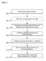
- FIG. 5 gives once again an overall view of the sequence of a configuration and programming a safety controller 10.
- a first step 300 an element is selected, which represents a sensor 20 or actuator 24 to be connected. It does not matter at this point, whether the element was originally present or a new element according to the invention, because by the method, which is based on the FIG. 4 has been described, new elements to the user are indistinguishable from the pre-existing elements, although it is optional to visually highlight them to indicate that they were not ex-factory.
- the selected functional unit 20, 24 is parameterized in a step 302, wherein in each case the acceptance of default settings can be sufficient. It is then stored in the middle window 106 in a step 304. In step 306, the user decides to select further functional units 20, 24 or to integrate the functional units 20, 24 stored in the window 106 into the security control. There are no restrictions with regard to the selection of further functional units, so the user can select and integrate further functional units 20, 24 at any time.
- connection modules 16a-b are assigned to inputs 18 and outputs 22 of suitable connection modules 16a-b by calling the assignment function in a step 308, whereby connection modules 16a-b are automatically exchanged or supplemented, as appropriate, in the window 106 shown.
- a step 310 the evaluation rules are determined, as described above FIG. 2 has been described.
- the configuration map shown in the display 100 is transferred to the real plant by placing and connecting appropriate lines between sensors 20, actuators 24 and the safety controller 10.
- the required functional units 20, 24 and the required control modules 10 and connection modules 16 can previously be ordered directly online via a mask or offline become.
- the configuration plan is printed or otherwise displayed, and the components are wired in the shop floor, without the need for deeper technical expertise than reading the plan.
- the configuration tool in a step 314, creates a control program by compiling subprograms corresponding to the logic arrays 36a-c and incorporating them into an overall program, which is transferred to the central controller 14.
- the controller 14 can then execute a test in a step 316 and thereby query all connected functional units 20, 24 according to their type, possibly transmit some or all of the set parameters to the functional unit 20, 24, so that their parameterization matches the configuration and determine, whether the connections were made correctly.
- terminals 18, 22 must be designed for a corresponding data communication, for example via IO-Link or a communication protocol, which can exchange the signals required for the data exchange at the terminals 18, 22.
- a transfer of data is conceivable in both directions: to the functional units 20, 24, to parameterize the latter, or in the reverse direction from the functional units 20, 24 to the safety controller 10 or the configuration tool to an actual parameterization or complete configuration in the Read in configuration tool.
- the controller 14 If the connections made are not correct, the controller 14 generates an error message with an indication of which functional units 20, 24 or which connections need to be changed. Such an indication is preferably displayed and edited again via the configuration tool. If the logic is compatible with the existing physical configuration, the controller 14 may also suggest that the control program be adapted instead of the wiring. Finally, the controller 14 may test each connected functional unit 20, 24 according to the test configuration or prompt for a self-test. Thereafter, the safety controller 10 is ready in a step 318.
- the security requirements described above for the safety controller 10 and normalized in the required safety category also apply to the configuration and programming, especially for the generation of the program and for the Transferring the program to the controller 14.
- the programming device itself may crash if necessary, as there are no sources of danger yet, the configuration created with it and the program must be fail-safe.
Abstract
Description
Die Erfindung betrifft ein Verfahren zum Programmieren und/oder Konfigurieren einer Sicherheitssteuerung nach dem Oberbegriff von Anspruch 1 sowie eine Vorrichtung zur Durchführung des Verfahrens gemäß Anspruch 9.The invention relates to a method for programming and / or configuring a safety controller according to the preamble of claim 1 and to an apparatus for carrying out the method according to claim 9.
Sicherheitssteuerungen dienen unter anderem dazu, bei Anliegen eines Gefahrensignals fehlerfrei auf eine vorgegebene Art zu reagieren. Eine typische Anwendung der Sicherheitstechnik ist die Absicherung gefährlicher Maschinen, wie etwa Pressen oder Roboter, die sofort abgeschaltet oder abgesichert werden müssen, wenn sich Bedienpersonal in unerlaubter Weise nähert. Dazu ist ein Sensor vorgesehen, der die Annäherung erkennt, wie etwa ein Lichtgitter oder eine Sicherheitskamera. Erkennt ein solcher Sensor eine Gefährdung, so muss eine mit dem Sensor verbundene Sicherheitssteuerung absolut zuverlässig ein Abschaltsignal generieren.Among other things, safety controllers are used to respond correctly to a specified type when a danger signal is present. A typical application of safety technology is to protect dangerous machinery, such as presses or robots, that need to be shut down or secured immediately when operating personnel are approaching inappropriately. For this purpose, a sensor is provided which detects the approach, such as a light grid or a security camera. If such a sensor detects a hazard, a safety controller connected to the sensor must generate a shutdown signal in an absolutely reliable manner.
In der Praxis überwacht zumeist nicht ein einzelner Sensor eine einzelne Maschine, sondern es müssen eine ganze Reihe von Gefährdungsquellen überwacht werden. Die entsprechende Vielzahl zugehöriger Sensoren, die jeweils ein Schaltereignis definieren können und geeigneter Maßnahmen zur Beseitigung von Gefährdungen muss dann in der Sicherheitssteuerung konfiguriert und verschaltet werden. Dabei ist eine fehlerfreie Konfiguration und Programmierung besonders wichtig, da sonst die Anlage nicht als sicher zertifiziert wird und damit nicht oder nur eingeschränkt eingesetzt werden kann.In practice, not a single sensor monitors a single machine, but a number of sources of danger must be monitored. The corresponding plurality of associated sensors, each of which can define a switching event and appropriate measures to eliminate hazards must then be configured and interconnected in the safety controller. In this case, a faultless configuration and programming is particularly important, otherwise the system is not certified as safe and thus can not or only partially be used.
Aus der
In der noch unveröffentlichten eigenen Anmeldung unter dem Aktenzeichen
Aus der
Es ist daher Aufgabe der Erfindung, eine Möglichkeit für die Programmierung oder Konfiguration einer Sicherheitssteuerung zu schaffen, welche eine möglichst hohe Flexibilität bietet.It is therefore an object of the invention to provide a way for the programming or configuration of a safety controller, which offers the highest possible flexibility.
Diese Aufgabe wird durch ein Verfahren zum Programmieren und/oder Konfigurieren gemäß Anspruch 1, eine entsprechende Vorrichtung gemäß Anspruch 9 sowie ein Computerprogrammprodukt gemäß Anspruch 10 gelöst. Der Begriff Sensor soll in einem sehr weiten Sinne als allgemeiner Signalgeber verstanden werden, der nicht unbedingt Ereignisse in der Umwelt detektiert, sondern beispielsweise auch wie ein Schalter oder eine Zeitschaltuhr Signale ausgibt. Die Steuerung kann in einer kompakten Ausführungsform Teil des Anschlussmoduls sein, welches dann gleichzeitig Steuerungs- und Anschlussmodul ist, gewöhnlich ist aber ein eigenes Steuerungsmodul vorgesehen. Die Steuerung kann zentral oder verteilt sein, und zwar sowohl über mehrere Module ein und derselben Modulreihe als auch verteilt über mehrere Modulreihen, welche untereinander über Feldbus oder dergleichen kommunizieren.This object is achieved by a method for programming and / or configuring according to claim 1, a corresponding device according to claim 9 and a computer program product according to
Die Erfindung geht von dem Grundgedanken aus, die Anzahl verfügbarer Sensoren und Aktoren erweiterbar zu machen. Damit können kunden- und anwendungsspezifische weitere Elemente auf möglichst einfache Weise hinzugefügt werden. Die neuen Elemente basieren auf einer Auswahl von Eigenschaften oder bewährten vorhandenen Elementen, um durch die neuen Elemente keine Fehler in die Sicherheitssteuerung einzuführen.The invention is based on the idea of making the number of available sensors and actuators expandable. In this way, customer-specific and application-specific further elements can be added in the simplest possible way. The new elements are based on a selection of properties or proven existing elements so as not to introduce errors into the safety control by the new elements.
Hier und im Folgenden sind unter dem neuen Element ein Name, ein Symbol, ein Icon oder eine sonstige Repräsentation in der grafischen Oberfläche sowie die zu diesem Element hinterlegten Eigenschaftsdefinitionen zu verstehen.Here and below, the new element means a name, a symbol, an icon or another representation in the graphical user interface as well as the property definitions stored for this element.
Jedes neue Element bildet eine Klasse mit bestimmten Eigenschaftsdefinitionen, Wertbereichen und Voreinstellungen, also Parametertypen. Das neue Element steht für einen Sensor oder Aktor, der zuvor nicht auswählbar war. Ein neues Element unterscheidet sich also von den vorhandenen Elementen nicht nur durch die Werte seiner Parameter, sondern durch die Definition der Parametertypen oder Eigenschaften an sich. Wird ein erfindungsgemäß erstelltes neues Element im weiteren Verlauf einer Konfiguration oder Programmierung ausgewählt oder instanziiert, so können die festgelegten Eigenschaften also nicht mehr im erfindungsgemäßen Sinne verändert, sondern ihnen lediglich noch Eigenschaften zugewiesen werden, und zwar in von der Festlegung der Eigenschaften des neuen Elements definierter Weise. Beispielsweise kann ein neues Element eine dreidimensionale Stereoskopiekamera sein und eine ihrer Eigenschaftsdefinitionen als der Basisabstand ihrer beiden Einzelkameras festgelegt werden. Das somit neu geschaffene Element kann dann in jeder späteren Konfiguration oder Programmierung nicht, einfach oder mehrfach ausgewählt und damit instanziiert werden, wobei für jede solche ausgewählte dreidimensionale Stereoskopiekamera ein voreingestellter Basisabstand übernommen oder ein individueller Abstandswert gesetzt werden kann.Each new element forms a class with specific property definitions, value ranges and default settings, ie parameter types . The new element represents a sensor or actuator that was previously not selectable. A new element thus differs from the existing elements not only by the values of its parameters, but also by the definition of the parameter types or properties per se. If a new element created according to the invention is selected or instantiated in the further course of a configuration or programming, then the defined properties can no longer be modified in accordance with the invention, but merely properties can be assigned to them, specifically as defined by the definition of the properties of the new element Wise. For example, a new element may be a three-dimensional stereoscopic camera and one of its property definitions set as the base distance of its two individual cameras. The thus newly created element can then not be selected once or multiple times in any subsequent configuration or programming and thus instantiated, wherein for each such selected three-dimensional stereoscopic camera, a preset basic distance can be adopted or an individual distance value can be set.
Vorteilhafterweise werden nach einer Auswahl Eingänge und/oder Ausgänge für ausgewählte Sensoren und/oder Aktoren durch Zuweisung von Werten zu den Eigenschaften parametriert, zusätzliche oder vorhandene Anschlussmodule ausgewählt, welche die benötigten Eingänge und/oder Ausgänge zur Verfügung stellen, die Sensoren und/oder Aktoren geeigneten Eingängen und/oder Ausgängen zugeordnet, Logikregeln festgelegt, nach denen Sensorsignale an den Eingängen der Sicherheitssteuerung zu Ansteuerungen für Aktoren an den Ausgängen der Sicherheitssteuerung verrechnet werden, die so entstandene Konfiguration durch Verbinden von Sensoren und/oder Aktoren mit Eingängen und/oder Ausgängen der Sicherheitssteuerung in einer von der Sicherheitssteuerung und den Sensoren und/oder Aktoren gebildeten Anlage umgesetzt, und das so entstandene Programm wird auf die zentrale Steuerung der Sicherheitssteuerung überspielt. Die von den neuen Elementen repräsentierten zusätzlichen Sensoren und Aktoren können damit in ein einfaches, sicheres und schnelles Verfahren zur Konfiguration und Programmierung einer Sicherheitssteuerung eingebunden werden.Advantageously, after a selection, inputs and / or outputs for selected sensors and / or actuators are parameterized by assigning values to the properties, additional or existing connection modules are selected which provide the required inputs and / or outputs, the sensors and / or actuators assigned to appropriate inputs and / or outputs, set logic rules, according to which sensor signals are offset at the inputs of the safety controller to controls for actuators at the outputs of the safety controller, the resulting configuration by connecting sensors and / or actuators with inputs and / or outputs of Safety control implemented in a system formed by the safety controller and the sensors and / or actuators, and the resulting program is transferred to the central control of the safety controller. The additional sensors and actuators represented by the new elements can thus be integrated into a simple, safe and fast method for configuring and programming a safety controller.
Die ausgewählten Elemente werden bevorzugt zunächst in einem Zwischenbereich abgelegt und dann durch Aufruf einer Zuordnungsfunktion automatisch sämtlichen von den in dem Zwischenbereich abgelegten Elementen repräsentierten Sensoren und/oder Aktoren Eingängen und/oder Ausgängen geeigneter Anschlussmodule zugeordnet. Alternativ kann die Zuordnungsfunktion auf eine eigene Auswahl von Elementen des Zwischenbereichs beschränkt ausgeführt werden. Mit dem einfachen Aufruf erspart sich der Anwender die sonst notwendigen Schritte, die Eingänge und Ausgänge der verfügbaren Anschlussmodule zu überprüfen, gegebenenfalls Anschlussmodule gegen solche eines anderen Typs auszutauschen oder weitere Anschlussmodule hinzuzufügen, so dass insgesamt die Sicherheitssteuerung genügend Anschlüsse für die ausgewählten Elemente in dem Zwischenbereich anbietet, und die Einzelzuordnung von jedem Anschluss jedes ausgewählten Elements zu einem geeigneten Anschluss der Sicherheitssteuerung. Die Konfiguration wird somit erheblich vereinfacht und beschleunigt.The selected elements are preferably first stored in an intermediate area and then automatically assigned to all sensors and / or actuators represented by the elements stored in the intermediate area by inputs and / or outputs of suitable connection modules by calling an assignment function. Alternatively, the mapping function may be limited to a separate selection of elements of the intermediate region. With the simple call, the user saves the otherwise necessary steps to check the inputs and outputs of the available connection modules, if necessary to exchange connection modules for those of a different type or to add further connection modules, so that overall the safety controller has enough connections for the selected elements in the intermediate area and the individual assignment of each port of each selected element to a suitable port of the security controller. The configuration is thus considerably simplified and accelerated.
Eigenschaften, welche zu neuen Elementen für die spätere Zuweisung festgelegt werden können, umfassen bevorzugt eine oder mehrere der Folgenden: Typbezeichnung, insbesondere Bestellnummer, Name, Hersteller; Anzahl der Anschlussklemmen; Art der Anschlüsse, insbesondere digital oder analog, einkanalig oder zweikanalig; Art des Signals, insbesondere antivalent, entgegengesetzt oder äquivalent, elektrische Größen wie Strom, Spannung, Kapazität; Kommunikationsprotokoll, insbesondere Art des Signals, Eingangs- und Ausgangsverzögerung, Diskrepanzzeit; physische Eigenschaften der Anschlüsse, insbesondere Drahtdurchmesser oder Steckertyp; Testmöglichkeiten, insbesondere Testsignale, Testdauer, Testzeitpunkt, erwartete Ausgaben bei einem Test, Dauer und Zeitpunkt der Testung. Dies alles sind Eigenschaften von Sensoren und Aktoren, welche für die Aufgaben der Sicherheitssteuerung relevant sind oder sein können und sie decken daher zumindest einen Großteil derjenigen Eigenschaften oder Parametertypen ab, die für die Einbindung eines neuen Elements für einen neuen Sensor oder Aktor benötigt werden könnten. Es ist denkbar, dass ein angeschlossener Sensor oder Aktor selbst seine Parameterliste mitbringt, also die Eigenschaftsdefinitionen an die grafische Benutzeroberfläche überträgt und dadurch festlegt und so selbst die Möglichkeit schafft, dass Sensoren oder Aktoren seiner Art in die Sicherheitssteuerung integriert werden.Properties which can be set to new elements for later assignment preferably comprise one or more of the following: type designation, in particular order number, name, manufacturer; Number of terminals; Type of connections, in particular digital or analog, single-channel or dual-channel; Type of signal, in particular complementary, opposite or equivalent, electrical quantities such as current, voltage, capacity; Communication protocol, in particular type of signal, input and output delay, discrepancy time; physical characteristics of the connections, in particular wire diameter or plug type; Test options, in particular test signals, test duration, test time, expected expenditure on a test, duration and time of the test. These are all characteristics of sensors and actuators that are or may be relevant to safety control tasks, and therefore cover at least a majority of those characteristics or parameter types that might be needed to incorporate a new element for a new sensor or actuator. It is conceivable that a connected sensor or actuator itself brings along its parameter list, that is, transmits the property definitions to the graphical user interface and thereby defines them, thereby creating the possibility for sensors or actuators of its kind to be integrated into the safety controller.
Die Repräsentation neuer Elemente in der grafischen Benutzeroberfläche ist vorteilhafterweise editierbar, insbesondere Name, Symbol, Anordnung in der Anzeige oder Anordnung in einem Menübaum. Damit können neue Elemente übersichtlich, auffällig, nach persönlichen Präferenzen oder möglichst fehlervermeidend benutzerdefiniert in die grafische Benutzeroberfläche integriert werden.The representation of new elements in the graphical user interface is advantageously editable, in particular name, symbol, arrangement in the display or arrangement in a menu tree. This means that new elements can be integrated into the graphical user interface in a clear, eye-catching way, according to personal preferences or as error-avoidant as possible.
Neue Elemente basieren bevorzugt auf einem oder mehreren Grundelementen, wobei die Festlegung, welche Eigenschaften den neuen Elementen zugewiesen werden können, durch Übernahme eines oder Auswahl aus einem globalen oder von den Grundelementen geerbten Katalog vorgenommen wird. Das Aufsetzen auf vorhandenen Elementen ist besonders dann von Vorteil, wenn nur geringfügige Änderungen vorzunehmen oder zumindest umfangreiche Festlegungen von bereits verfügbaren Elementen übernommen werden können. Für die neuen Elemente können aber auch zusätzliche Eigenschaften festgelegt werden, welche keines der Grundelemente aufweisen. Der Katalog möglicher Eigenschaften umfasst also eine Auswahl denkbarer Eigenschaften von Sensoren und Aktoren, welche die Sicherheitssteuerung verarbeiten kann, und/oder die Vereinigungsmenge derjenigen Eigenschaften, welche die Grundelemente besitzen. Dabei sind aus Sicht der Sicherheitssteuerung zunächst nur die Eigenschaften an den Eingängen und Ausgängen relevant, weil das die Verbindung zu den Sensoren und Aktoren darstellt, aber auch weitere Eigenschaften können über die Sicherheitssteuerung festgelegt und später parametriert werden. Grundelemente sind sowohl solche, mit denen die grafische Benutzeroberfläche ausgeliefert wird, als auch gespeicherte oder importierte Elemente, die erfindungsgemäß erstellt worden sind.New elements are preferably based on one or more primitives, whereby the determination of which properties can be assigned to the new elements is made by adopting or selecting from a global or inherited from the primitive catalog. The touchdown on existing elements is particularly advantageous if only make minor changes or at least extensive definitions of already available elements can be adopted. For the new elements but also additional properties can be set, which have none of the basic elements. The catalog of possible properties thus comprises a selection of conceivable properties of sensors and actuators which the safety controller can process, and / or the union of those properties which the basic elements possess. Initially, only the characteristics at the inputs and outputs are relevant from the point of view of the safety controller, because this is the connection to the sensors and actuators, but other properties can also be defined via the safety controller and parameterized later. Basic elements are both those with which the graphical user interface is delivered, as well as stored or imported elements that have been created according to the invention.
Die ausgewählten oder geerbten Eigenschaften werden noch bevorzugter bei der Festlegung angepasst, indem für die spätere Auswahl Voreinstellungen, Wertbereiche, zusätzliche Einstellmöglichkeiten und/oder reduzierte Einstellmöglichkeiten vorgegeben werden. Durch die Festlegung der Eigenschaften wird, wie mehrfach erläutert, nur das Gerüst vorgegeben, also dass ein Element die Eigenschaft überhaupt aufweist. Wird ein neues Element später tatsächlich ausgewählt, so muss es noch parametriert werden, also Werte für die Eigenschaften gewählt werden. Um dies zu erleichtern und vor allem die Sicherheit zu gewährleisten, werden Voreinstellungen angeboten oder Wertbereiche begrenzt. Soweit geerbte Eigenschaften betroffen sind, ist es manchmal sinnvoll, dem neuen Element zusätzliche Einstellungsmöglichkeiten zu geben, also etwa einen neuen Wertebereich, eine weitere Bedingung oder einen Zusatzparameter. Umgekehrt werden bei der Festlegung manche Eigenschaften als grau hinterlegt oder als versteckt gekennzeichnet, so dass bei späterer Auswahl der Wert dieser Eigenschaft nicht mehr veränderbar oder sogar nicht mehr sichtbar ist. Dabei steht, wie bei anderen Ausführungsformen, die Idee im Hintergrund, dass das Anlegen neuer Elemente von einem Anwender mit tieferen technischen Kenntnissen vorgenommen wird als die spätere Auswahl. Dies kann durch besondere Authentifizierung für das Erzeugen oder Ändern neuer Elemente unterstützt werden, denn die Folgen eines falschen Voreinstellungswerts, den ein Anwender oft ohne weiteres Überlegen übernimmt, ist schwerwiegender als die konkrete Einstellung eines Parameters.The selected or inherited properties are more preferably adjusted in the determination by presetting, value ranges, additional setting options and / or reduced setting options for the subsequent selection. By defining the properties, as explained in more detail, only the framework is specified, ie that an element has the property at all. If a new element is actually selected later, it still has to be parameterized, ie values for the properties must be selected. In order to facilitate this and above all to ensure safety, presettings are offered or value ranges are limited. As far as inherited properties are concerned, it sometimes makes sense to give the new element additional setting options, such as a new value range, another condition or an additional parameter. Conversely, some properties are marked as gray or hidden in the definition, so that the value of this property is no longer changeable or even no longer visible when later selected. It stands, as in other embodiments, the idea in the background that the creation of new elements is made by a user with deeper technical knowledge than the subsequent selection. This can be supported by special authentication for creating or changing new elements, because the consequences of a wrong default value, which a user often takes over without further consideration, is more serious than the concrete setting of a parameter.
Nach der Festlegung, welche Eigenschaften den neuen Elementen zugewiesen werden können, wird vorteilhafterweise überprüft, ob das neue Element ein sicheres Element ist, insbesondere ob das neue Element unabhängig von der späteren Zuweisung von Eigenschaften schon durch die Festlegung sicher ist. Dafür sind verschiedenste Tests denkbar, wie das Prüfen von Voreinstellungen, Wertbereichen, von Bedingungen, wo und wie ein neues Element anschließbar ist, welche Eigenschaften miteinander verträglich sind. Beispielsweise ist ein Not-Aus-Schalter mit einer Latenz von mehreren Sekunden oder einer unsicheren einkanaligen Anbindung ungeeignet. Darauf weist die grafische Benutzeroberfläche zumindest mit einer Warnung oder mit einer Verweigerung der Erstellung eines solchen Elements hin. Außerdem können zu dem neuen Element Testmuster hinterlegt werden, um einen späteren Test der vollständig konfigurierten und parametrierten Sicherheitssteuerung zu unterstützen. Denn komplexere Tests, wie diejenigen der Logik, lassen sich noch nicht vollständig auf Basis eines neuen Elements durchführen, da die Funktionalität erheblich von der späteren konkreten Parametrierung und physischen wie logischen Einbindung abhängt.After determining which properties can be assigned to the new elements, it is advantageously checked whether the new element is a secure element, in particular whether the new element is safe even by the definition, regardless of the later assignment of properties. For this, a variety of tests are conceivable, such as checking presettings, value ranges, conditions, where and how a new element can be connected, which properties are compatible with one another. For example, an emergency stop switch with a latency of several seconds or an unsafe single-channel connection is unsuitable. This is indicated by the graphical user interface at least with a warning or with a refusal to create such an element. In addition, test patterns can be stored for the new element in order to support a later test of the fully configured and parameterized safety controller. Because more complex Tests, such as those of logic, can not yet be completely carried out on the basis of a new element, since the functionality depends considerably on the later concrete parameterization and physical as well as logical integration.
Die Erfindung wird nachstehend auch hinsichtlich weiterer Merkmale und Vorteile beispielhaft anhand von Ausführungsformen und unter Bezug auf die beigefügte Zeichnung näher erläutert. Die Abbildungen der Zeichnung zeigen in:
- Fig. 1
- die beispielhafte Darstellung einer Anzeige einer grafischen Benutzeroberfläche für die Konfiguration und/oder Programmierung einer Sicherheitssteuerung;
- Fig. 2
- eine rein beispielhafte logische Verknüpfung der Sensoren und Aktoren für die Auswahl und Einstellung der Auswertungsregeln für das Programm der Sicherheitssteuerung;
- Fig. 3
- eine schematische Darstellung einer modularen Sicherheitssteuerung mit angeschlossenen Sensoren und Aktoren, die erfindungsgemäß konfiguriert und/oder programmiert werden kann;
- Fig. 4
- ein Ablaufschema der erfindungsgemäßen Erzeugung neuer Elemente, die nach ihrer Erzeugung in der grafischen Benutzeroberfläche gemäß
Figur 1 für die Konfiguration und/oder Programmierung verfügbar sind; und - Fig.5
- ein Ablaufschema der Konfiguration und/oder Programmierung mit Elementen beziehungsweise erfindungsgemäß erzeugten neuen Elementen.
- Fig. 1
- the exemplary representation of a display of a graphical user interface for the configuration and / or programming of a safety controller;
- Fig. 2
- a purely exemplary logical connection of the sensors and actuators for the selection and setting of the evaluation rules for the program of the safety controller;
- Fig. 3
- a schematic representation of a modular safety controller with sensors and actuators connected, which can be configured and / or programmed according to the invention;
- Fig. 4
- a flowchart of the inventive generation of new elements that after their creation in the graphical user interface according to
FIG. 1 are available for configuration and / or programming; and - Figure 5
- a flowchart of the configuration and / or programming with elements or inventively generated new elements.
Die Sicherheitssteuerung hat die Aufgabe, für einen sicheren Betrieb der Sensoren 20a-c und vor allem der Aktoren 24a-b zu sorgen, also Aktoren 24a-b sicherheitsgerichtet abzuschalten (der Ausgang 22 ist dann ein OSSD, Output Switching Signal Device), ein Not-Aus der Anlage sicher auszuführen, einer beliebigen Ansteuerung an einen Aktor 24a-b, besonders einem Einschalten oder einem Wiederhochfahren zuzustimmen, Aktoren 24a-b freizugeben und dergleichen.The safety controller has the task of ensuring safe operation of the
Ein Lichtgitter 20b, eine Sicherheitskamera 20a und ein Schalter 20c sind Beispiele für sicherheitsrelevante Sensoren oder Eingänge, welche ein Signal liefern können, auf das als Reaktion eine sicherheitsgerichtete Abschaltung erfolgt. Dies kann eine Unterbrechung der Lichtstrahlen des Lichtgitters 20b durch ein Körperteil, die Erkennung eines unzulässigen Eingriffs in einen Schutzbereich durch die Sicherheitskamera 20a oder ein Betätigen des Schalter 20c sein. An die Eingänge 18 können weitere Sicherheitssensoren beliebiger Art, wie Laserscanner, 3D-Kameras, Schaltmatten oder kapazitive Sensoren angeschlossen werden, aber auch sonstige Sensoren etwa zur Aufnahme von Messdaten oder einfache Schalter wie ein Not-Aus-Schalter. Alle derartigen Signalgeber werden hier und im Folgenden als Sensor bezeichnet.A
Bei bestimmten Anwendungen sind auch Sensoren 20 an Ausgänge 22 und Aktoren 24 an Eingänge 18 angeschlossen, etwa um Testsignale zu übertragen, um einen Sensor 20 vorübergehend stumm zu schalten (muting), Teilbereiche aus dem Überwachungsbereich des Sensors 20 auszublenden (blanking), oder weil ein Aktor 24 neben einem Eingang für Ansteuerungen auch eigene Signalausgänge besitzt, mit denen er sich zum Teil selbst überwacht.In certain applications,
Ein Roboter 24a und eine Abkantpresse 24b sind als Beispiele Bedienpersonal bei unzulässigem Eingriff gefährdender Aktoren bevorzugt zweikanalig an Ausgänge 22 angeschlossen und können somit von dem Sicherheitsschaltgerät 10 einen Abschaltbefehl erhalten, um bei Erkennung einer Gefährdung oder eines unzulässigen Eingriffs durch Sicherheitssensoren 20a-b die Aktoren 24a-b abzuschalten oder in einen sicheren Zustand zu verbringen. Dabei kann das Lichtgitter 20a der Überwachung der Abkantpresse 24a und die Sicherheitskamera 20b der Überwachung des Roboters 24b dienen, so dass einander funktionell zugehörige Sensoren 20a-b und Aktoren 24a-b auch jeweils an einem Modul 16a bzw. 16b angeschlossen sind. Die funktionelle Zuordnung erfolgt aber über die zentrale Steuerung 14, so dass eine solche Abbildung der Anlage zwar übersichtlicher, keineswegs aber erforderlich ist. Weitere als die dargestellten Aktoren sind denkbar, und zwar sowohl solche, welche einen Gefahrenbereich erzeugen als auch andere, etwa eine Warnlampe, eine Sirene, eine Anzeige und dergleichen mehr.A
Zwischen der Sicherheitssteuerung 14 und den Eingängen 18 bzw. den Ausgängen 22 besteht eine Backplane genannte serielle Kommunikationsverbindung 26, die insbesondere ein Bus ist und auf einem seriellen Standard, einem Feldbusstandard, wie IO-Link, Profibus, CAN oder auch einem proprietären Standard basieren und zusätzlich auch fehlersicher ausgelegt sein kann. Alternativ zu einem Bus kann auch eine direkte, eine parallele Verbindung oder eine sonstige den zu kommunizierenden Datenmengen und den erforderlichen Schaltzeiten entsprechende Verbindung 26 vorgesehen sein. Die Module 16a-d weisen eine eigene Steuerung auf, um an der Buskommunikation teilnehmen zu können. Hierfür kann ein Mikroprozessor, ein FPGA, ein ASIC, eine programmierbare Logik oder ein ähnlicher digitaler Baustein vorgesehen sein. Die Steuerungen 18 können auch Auswertungsaufgaben übernehmen oder gemeinsam mit der zentralen Steuerung 14 verteilte Auswertungen vornehmen, die von einfachen Bool'schen Verknüpfungen bis hin zu komplexen Auswertungen, etwa einer dreidimensionalen Sicherheitskamera, reichen können.Between the
Das Sicherheitsschaltgerät 10 kann über ein Gateway, welches ein eigenes Modul bildet oder in die Sicherheitssteuerung 14 integriert ist, an eine externe Anlagensteuerung angeschlossen sein, welche mit nicht sicherheitsrelevanten Steuerungsaspekten befasst ist. Die Anbindung kann drahtlos oder drahtgebunden, in der Praxis meist über einen Feldbus erfolgen. Gibt die externe Steuerung einen Befehl an einen der Aktoren 24, und zwar alternativ über die Ausgänge 22, welche auch Abschaltsignale ausgeben können, oder auf eigene Ausgänge, so wird er nur dann wirksam, wenn die Sicherheitssteuerung 14 zustimmt, also etwa durch UND-Verknüpfung von Ansteuerung und Zustimmungssignal. Damit wird verhindert, dass die externe Anlagensteuerung eine gefährliche Situation schafft. Die externe Steuerung kann umgekehrt eine Abschaltung der Aktoren 24 nicht verhindern, da die Sicherheitsaufgaben durch die Sicherheitssteuerung 10 gesteuert werden.The
Die Module 12, 16a-d sind jeweils in einheitlichen Gehäusen untergebracht und werden durch Anschlussstücke mechanisch und elektrisch miteinander verbunden. Das Steuerungsmodul 12 bildet somit den Kopf einer Modulreihe. Denkbar ist auch, dass mehrere Steuerungsmodule 12 als Kopf mehrerer Modulreihen dezentral angeordnet sind, etwa jeweils in der Nähe der zu überwachenden Teile der Gesamtanlage, die untereinander über einen Feldbus kommunizieren.The
Sicherheitssteuerung 14, Eingänge 18, Ausgänge 22 und Bus 26 sind fehlersicher ausgebildet, also durch Maßnahmen wie zweikanalige Ausführung, durch diversitäre, redundante, selbstprüfende oder sonst sichere Auswertungen und Selbsttests. Entsprechende Sicherheitsanforderungen für die Sicherheitssteuerung sind in der Norm EN 954-1 bzw. ISO 13849 (performance level) festgelegt. Die damit mögliche Sicherheitsstufe und die weiteren Sicherheitsanforderungen an eine Anwendung sind in der Norm EN 61508 bzw. EN 62061 definiert.
Die Erfindung betrifft die Konfiguration und Programmierung der Sicherheitssteuerung 10. Dabei wird unter Konfigurieren die Auswahl von Elementen 12, 16, 20, 24 sowie deren physische Anordnung und Verbindung beziehungsweise Verdrahtung verstanden. Programmieren ist das auf Basis von Benutzerangaben automatische Erzeugen und Zusammenfügen von der Konfiguration entsprechenden Programmteilen unter Einbeziehung logischer Auswertungsregeln, welche die Elemente 12, 16, 20, 24 miteinander verbinden, um Eingangssignale der Sensoren 20 zu Ansteuerungen an die Aktoren 24 zu verrechnen. Das Vorgeben der Logik, also der logischen Auswertungsregeln, ist eine Mischung aus Konfigurieren und Programmieren, denn der Anwender muss lediglich die logischen Verbindungsregeln vorgeben, was einer Konfiguration nahe kommt, während daraus aber erfindungsgemäß automatisch anhand der zu den Verbindungsregeln hinterlegten Programmteile das Programm für die Sicherheitssteuerung 10 generiert wird, worin eher ein Programmieren liegt. Im Folgenden wird meist vereinfachend der Begriff Konfigurieren verwendet, welcher situationsabhängig eine Programmierung einschließen soll.The invention relates to the configuration and programming of the
Anhand der Anzeige 100 wird nun beschrieben, wie ein Anwender die Konfigurierung der Sicherheitssteuerung 10 mit Hilfe der grafischen Benutzeroberfläche durchführt.The
Die Anzeige 100 bietet in einem linken Fenster 102 an die Sicherheitssteuerung 10 anschließbare Elemente an, nämlich Sensoren oder Eingangsklassen (input class) 20, Aktoren oder Ausgangsklassen (output class) 24 und Teilapplikationen (applications) 30. Neben der dargestellten Sicherheitskamera 20a, dem Lichtgitter 20b, einem Schalter 20c und einer Lichtschranke 20d umfassen die Eingangsklassen weitere zwei- und dreidimensionale Sicherheitskameras, Mutingsensoren, Sicherheitsmatten, Bumper, Sicherheitsschalter einschließlich Not-Aus-Schaltern, Zweihandschaltungen und weitere Geräte, die ein möglicherweise sicherheitsrelevantes Eingangssignal für die Sicherheitssteuerung 10 liefern können. Als Ausgangsklassen kommen über die dargestellten Roboter 20a, Pressen 20b und eine Lichtschranke 20c jegliche Maschinen, Roboter, Fahrzeuge, Lampen, Sirenen, aber auch Sensoren in Frage, die ein Feedback erhalten sollen, etwa zur vorübergehenden Deaktivierung (muting, blanking). Erfindungsgemäß ist vorgesehen, die Elemente der Eingangs- und Ausgangsklassen zu erweitern, also die Möglichkeit zu schaffen, neue Elemente für die spätere Auswahl zu generieren. Diese Erzeugung neuer Elemente wird weiter unten im Zusammenhang mit
In einem rechten Fenster 104 wird die Sicherheitssteuerung 10 mit Steuerungsmodul 12 und Anschlussmodulen 16a-b samt ihren Eingängen 18 und Ausgängen 22 angezeigt. Auch das Steuerungsmodul 10 kann Eingänge und/oder Ausgänge aufweisen. Das Steuerungsmodul 12 hat eine Buchse 32 und jedes Anschlussmodul 16 eine Buchse 32 und einen Stecker 34, um die Sicherheitssteuerung 10 als mechanisch einheitliche Modulreihe zusammenstecken zu können. Die Erfindung ist darauf nicht notwendig beschränkt, denn die Module können auch physisch voneinander getrennt sein, solange sie logisch verbunden bleiben. Mit einem kleinen Icon in einem Eingang 18 oder einem Ausgang 22 wird bildlich dargestellt, mit welchem Sensor 20 oder Aktor 24 dieser Anschluss 18, 22 verbunden sein soll. Das rechte Fenster 104 zeigt somit die Konfiguration von Modulen 12, 16a-b, die angeschlossenen Sensoren 20 und Aktoren 24 sowie die Zuordnung zu bestimmten Eingängen 18 und Ausgängen 22.In a right-
Die Arbeitsschritte eines Benutzers, die zu einer solchen Konfiguration führen, sind die Folgenden: Aus den angebotenen Eingangs- und Ausgangsklassen wird ein benötigter Sensor 20 oder Aktor 24, im Folgenden manchmal zusammenfassend als Funktionseinheit 20, 24 bezeichnet, ausgewählt. Diese Funktionseinheit 20, 24 wird anschließend parametriert, indem durch verschiedene Fenster und Schaltflächen Werte, Modi und dergleichen eingestellt werden. Die derart parametrierte Funktionseinheit 20, 24 wird zunächst in einem mittleren Fenster 106 (Parking area) abgelegt. Mit Auswahl weiterer Funktionseinheiten 20, 24 werden diese Schritte wiederholt, bis sämtliche oder eine gewünschte Teilmenge der benötigten Funktionseinheiten 20, 24 in dem mittleren Fenster 106 abgelegt sind.The working steps of a user leading to such a configuration are the following: From the offered input and output classes becomes a required
Mit Aufruf einer Zuordnungsfunktion werden dann automatisch eine Reihe weiterer Konfigurationsschritte ausgeführt. Selbstverständlich ist in einer alternativen, weniger komfortablen Ausführungsform möglich, diese Schritte einzeln von Hand auszuführen. Die Zuordnungsfunktion berücksichtigt sämtliche Funktionseinheiten 20, 24 in dem mittleren Fenster 106, kann aber auch auf eine durch Benutzerauswahl definierte Teilauswahl eingeschränkt werden.When a mapping function is called, a number of further configuration steps are then automatically executed. Of course, in an alternative, less convenient embodiment, it is possible to carry out these steps individually by hand. The mapping function considers all
Zuerst wird bestimmt, welche Eingänge 18 und Ausgänge 22 die Funktionseinheiten 20, 24 benötigen. Die hierfür geeigneten Anschlussmodule 16a-b werden ausgewählt. Sind nicht mehr genug Anschlüsse 18, 22 für die gewählten Funktionseinheiten 20, 24 vorhanden, so muss ein weiteres Anschlussmodul 16a-b angefügt oder ein vorhandenes durch ein solches mit mehr Anschlüssen ausgetauscht werden. Die somit ausreichend verfügbaren Anschlüsse 18, 22 werden dann den Funktionseinheiten 20, 24 zugeordnet und damit entschieden, an welche Eingänge 18 und Ausgänge 22 jede Funktionseinheit 20, 24 anzuschließen ist. Dabei kann eine Funktionseinheit 20, 24 mehrere Eingänge 18 und/oder Ausgänge 22 belegen. Dann werden die Funktionseinheiten 20, 24 in das rechte Fenster 104 verschoben, und zwar optisch als Symbol in jedem mit der Funktionseinheit 20, 24 verschalteten Eingang oder Ausgang. Im rechten Fenster 104 wird damit die fertige Konfiguration der Funktionseinheiten des mittleren Fensters 106 dargestellt.First, it is determined which
Die von der Zuordnungsfunktion gewählten Verbindungen können aber weiterhin jederzeit verändert werden. So kann eine Funktionseinheit 20, 24 wieder entfernt, in das mittlere Fenster 106 zurückgeschoben oder von dort durch erneuten Aufruf der Zuordnungsfunktion wieder angeschlossen werden. Manuelle oder automatische Optimierung kann dafür genutzt werden, die vorhandenen Anschlussmodule 16 auszunutzen, mit weniger Anschlussmodulen 16 auszukommen oder für größere logische oder optische Übersicht zu sorgen.However, the connections selected by the assignment function can still be changed at any time. Thus, a
Nachdem somit die physische Zuordnung festgelegt ist, muss noch die logische Verknüpfung geschaffen werden.
Werden physische Verbindungen von Funktionseinheiten 20, 24 im Rahmen einer Optimierung oder einer manuellen Änderung vertauscht, nachdem die Logik schon definiert wurde, also Funktionseinheiten 20, 24 anderen Eingängen 18 oder Ausgängen 22 desselben oder eines anderen Ausgangsmoduls 16a-b zugewiesen, so verändert sich dabei die Logik nicht. Die logischen Auswertungsregeln sind invariant gegenüber solchen Vertauschungen; sie werden bei der abschließenden Generierung des Steuerungsprogramms automatisch richtig berücksichtigt.If physical connections of
Mit Begriffen wie Auswählen, Verbinden und dergleichen sind im Zusammenhang mit der grafischen Benutzeroberfläche Symbole für Sensoren 20, Aktoren 24, Module 12, 16, Verbindungen, Logikelemente 36a-c und entsprechende Logikregeln über Menüs, Icons, Drag & Drop und dergleichen gemeint. Eine physische Verdrahtung folgt erst anschließend anhand des Konfigurationsplans.By terms such as selecting, connecting, and the like, in the context of the graphical user interface are meant symbols for
Alternativ zu einzelnen Funktionseinheiten 20, 24 können auch vorgefertigte, mehrfach gebrauchte oder standardisierte Teilapplikationen 30 eingebunden werden. Diese bringen ihre zugehörigen parametrierten Funktionseinheiten 20, 24 sowie die innere logische Verknüpfung bereits mit, so dass nur noch die äußere logische Verknüpfung vorgenommen werden muss, indem Freigaben und Abschaltpfade definiert werden. Ein Beispiel unter vielen ist ein sogenanntes "sequential muting", bei dem einige Lichtstrahlen eines Lichtgitters nacheinander stumm geschaltet werden, beispielsweise damit das erlaubte Durchfahren einer Palette mit bekannten geometrischen Eigenschaften nicht zu einem Abschaltsignal führt. Solche Teilapplikationen beschleunigen die Konfiguration und machen sie fehlersicherer, weil die innere Konfiguration der Teilapplikation nur einmal, auch ab Werk oder durch einen Experten, vorgegeben werden.As an alternative to individual
Anhand der
In einem ersten Schritt 200 wird über die grafische Benutzeroberfläche der Befehl erteilt, ein neues Element zu erstellen. In vielen Fällen beruht dieses neue Element auf einem oder mehreren bestehenden Elementen, welche in einem zweiten Schritt 202 ausgewählt werden. Basiselemente, die häufig als Grundlage dienen können, sind einkanalige oder zweikanalige Eingänge oder Ausgänge (aus der Sicht der Funktionseinheiten bezeichnet, demnach korrespondierend zu später zu verbindenden Ausgängen 22, beziehungsweise Eingängen 18 der Anschlussmodule 16). Wenn aber beispielsweise ein Nachfolgemodell eines vorhandenen Lichtgitters 20b als neues Element eingefügt werden soll, so wird das Element für das Vorgängermodell das geeignete Basiselement sein. Der Schritt 202 ist optional und daher gestrichelt dargestellt, weil es auch möglich ist, neue Elemente unabhängig von vorhandenen Elementen von Grund auf neu zu erstellen.In a
Die Informationen zu dem neuen Element werden als dessen Eigenschaften in einem Schritt 206 festgelegt. Im Gegensatz zu einer vollständigen Programmiersprache bietet die Benutzeroberfläche nicht beliebige Eigenschaften an, sondern einen Katalog von mit einer sicheren Konfiguration vereinbaren Eigenschaften. Dieser Katalog kann aus einer vollständigen Auflistung aller von der Sicherheitssteuerung 10 verarbeitbaren Eigenschaften bestehen, aber auch von der grafischen Benutzeroberfläche begrenzt werden, besonders auf diejenigen Eigenschaften, welche in Schritt 202 bezeichnete Basiselemente aufweisen können. Zwischen den Eigenschaften können Bedingungen definiert sein, welche weitere Eigenschaften freischalten oder entfernen. So ist etwa nicht sinnvoll, für eine als einkanalig bezeichnete Funktionseinheit 20, 24 noch Eigenschaften anzubieten, welche sich auf das Verhältnis der beiden Kanäle einer zweikanaligen Ausführung beziehen.The information about the new item is set as its properties in a
Beispiele für Eigenschaften, die festgelegt werden können, sind Typbezeichnungen einschließlich Bestellnummer, Name oder Hersteller, die Anzahl der Anschlussklemmen, die Art der Anschlüsse, insbesondere ob digital oder analog, die einkanalige oder zweikanalige Anbindung, die Art des Signals, insbesondere ob sich die beiden Kanäle eines zweikanaligen Anschlusses antivalent, entgegengesetzt oder äquivalent verhalten, elektrische Größen wie Strom, Spannung oder Kapazität, ein Kommunikationsprotokoll, also eine Einigung zwischen zentraler Steuerung 14 und der von dem neuen Element repräsentierten Funktionseinheit 20, 24 über die Signalübertragung, welches beispielsweise die Art des Signals, die Eingangs- und Ausgangsverzögerung oder eine Diskrepanzzeit (Zeit, innerhalb derer die beiden Kanäle eines zweikanaligen Anschlusses dasselbe Signal anzeigen müssen, damit es als gültig erkannt wird) festlegt, physische Eigenschaften der Anschlüsse, insbesondere Drahtdurchmesser oder Steckertyp sowie Testmöglichkeiten einschließlich Testsignale, Testdauer, Testzeitpunkt, erwartete Ausgaben bei einem Test, Dauer oder Zeitpunkt der Testung und weitere denkbare Größen wie Kompatibilität zu der Norm IEC61131-2. Die Eigenschaften müssen also die vollständige und sichere Einbindung in die Sicherheitssteuerung 10 ermöglichen, vor allem hinsichtlich sicherheitsgerichteter Sensordaten und Abschaltsignale. Manche neu einzubindenden Funktionseinheiten 20, 24 erfordern auch Parameter, die bisher nicht vorgesehen waren und deren Definition die Funktionseinheit 20, 24 selbst als Erweiterung des Konfigurationswerkzeugs mitbringt.Examples of properties that can be defined are type designations including order number, name or manufacturer, the number of terminals, the type of connections, especially whether digital or analogue, the single-channel or dual-channel connection, the type of signal, especially if the two Channels of a dual-channel terminal complementary, opposite or equivalent behavior, electrical variables such as current, voltage or capacity, a communication protocol, ie an agreement between the
In einem Schritt 206 werden für die festgelegten Eigenschaften Voreinstellungen vorgenommen oder zulässige Wertebereiche angegeben. In einem Schritt 208 wird definiert, ob Eigenschaften editierbar sind, ob also eine Voreinstellung später bei der Parametrierung nur ein Vorschlag oder eine feste Einstellung ist. So ist zum Beispiel der Typ des neuen Elements keine sinnvoll zu editierende Eigenschaft, da sie konstant für alle späteren Instanzen des neuen Elements gilt. Dagegen wäre ein Name eine editierbare Eigenschaft, da sie sich auf die Instanz bezieht und gewöhnlich individuell zugewiesen wird. Nicht editierbare Eigenschaften können bei der Parametrierung ausgeblendet oder optisch markiert werden, beispielsweise grau hinterlegt.In a
In einem Schritt 208 werden dem neuen Element ein Name, ein Symbol zur Darstellung in der Anzeige 200 sowie eine räumliche und inhaltliche Anordnung zugewiesen. Damit kann es dann später innerhalb des richtigen Menüs mit einem verständlichen Namen und einem aussagekräftigen Icon zur Auswahl aufgefunden werden. Spätestens jetzt wird auch bestimmt, ob es sich um eine Eingangs- oder Ausgangsklasse handelt und innerhalb dessen nach Möglichkeit eine sinnvolle Kategorie zugewiesen, also Lichtschranke, Lichtgitter, Laserscanner, Sicherheitskamera, Not-Aus-Schalter, Werkzeugmaschine, Roboter, Signallampe, Sirene und dergleichen.In a
Damit ist das neue Element fertig und steht mit einem Schritt 212 als zusätzliche Auswahlmöglichkeit im Fenster 202 zur Verfügung. Das erfindungsgemäße Verfahren hat somit auf einer sehr anschaulichen Erklärungsebene festgelegt, welche Fenster und Schaltflächen später bei der Auswahl des neuen Elements zur Parametrierung angezeigt werden, während die Parametrierung selbst in der Eingabe geeigneter Größen in diese Fenster und Schaltflächen besteht.This completes the new element and is available with a
Bevor das neue Element auf der grafischen Benutzeroberfläche auswählbar wird, kann es noch getestet werden. Dies kann automatisch oder durch Freigabe eines eigens authentifizierten Experten geschehen. Dabei geht es um die Frage, ob die festgelegten Eigenschaften die Funktionseinheit für Sicherheitsaspekte abschließend beschreiben können, ob die Voreinstellungen und Wertebereiche die Sicherheit gewährleisten, ob die angestrebten Schalt- und Reaktionszeiten erreicht werden und Weiteres.Before the new element can be selected in the graphical user interface, it can still be tested. This can be done automatically or by releasing a specially authenticated expert. It deals with the question of whether the specified properties can describe the functional unit for safety aspects conclusively, whether the default settings and value ranges guarantee safety, whether the desired switching and reaction times are achieved and others.
Als Alternative zu dem soeben beschriebenen Verfahren ist denkbar, dass eine Funktionseinheit 20, 24 physisch an die Sicherheitssteuerung 10 angeschlossen wird und eine Beschreibungsdatei überträgt, welche neue Elemente definiert. Dabei handelt es sich um die Beschreibungsdatei der Funktionseinheit 20, 24 selbst, die somit dafür sorgt, dass das Konfigurationswerkzeug mit ihr umgehen kann, aber möglicherweise auch um weitere Funktionseinheiten 20, 24, um auf diese einfache Weise die grafische Benutzeroberfläche zu erweitern und zu aktualisieren. Die neuen Elemente können darüber hinaus auch auf einem beliebigen Speichermedium ex- und importiert werden.As an alternative to the method just described, it is conceivable that a
Die ausgewählte Funktionseinheit 20, 24 wird in einem Schritt 302 parametriert, wobei jeweils das Akzeptieren von Voreinstellungen ausreichen kann. Sie wird dann in einem Schritt 304 in dem mittleren Fenster 106 abgelegt. Im Schritt 306 entscheidet sich der Anwender, weitere Funktionseinheiten 20, 24 auszuwählen oder die in dem Fenster 106 abgelegten Funktionseinheiten 20, 24 in die Sicherheitssteuerung einzubinden. Dabei gibt es keine Beschränkungen hinsichtlich der Auswahl weiterer Funktionseinheiten, der Anwender kann also jederzeit weitere Funktionseinheiten 20, 24 auswählen und einbinden.The selected
Die in dem mittleren Fenster abgelegten Funktionseinheiten 20, 24 werden durch Aufruf der Zuordnungsfunktion in einem Schritt 308 Eingängen 18 und Ausgängen 22 geeigneter Anschlussmodule 16a-b zugeordnet, wobei gegebenenfalls Anschlussmodule 16a-b automatisch ausgetauscht oder ergänzt werden, und dies entsprechend in dem Fenster 106 dargestellt.The
In einem Schritt 310 werden die Auswertungsregeln festgelegt, wie dies oben im Zusammenhang mit
In einem Schritt 312 wird der in der Anzeige 100 gezeigte Konfigurationsplan in die reale Anlage übertragen, indem entsprechende Leitungen zwischen Sensoren 20, Aktoren 24 und der Sicherheitssteuerung 10 gelegt und angeschlossen werden. Die benötigten Funktionseinheiten 20, 24 sowie die benötigten Steuerungsmodule 10 und Anschlussmodule 16 können zuvor direkt über eine Maske online oder offline bestellt werden. Der Konfigurationsplan wird ausgedruckt oder anders angezeigt und die Komponenten werden in der Werkhalle verdrahtet, ohne dass hierfür eine tiefere technische Kompetenz erforderlich wäre als das Lesen des Plans.In a
Aus der grafisch entworfenen Logik erstellt das Konfigurationswerkzeug in einem Schritt 314 ein Steuerungsprogramm durch Zusammenstellen von den Logikbausteinen 36a-c entsprechenden Teilprogrammen und Einbindung in ein Gesamtprogramm, welches auf die zentrale Steuerung 14 überspielt wird.From the graphically designed logic, the configuration tool, in a
Die Steuerung 14 kann dann in einem Schritt 316 einen Test ausführen und dabei sämtliche angeschlossene Funktionseinheiten 20, 24 nach ihrem Typ abfragen, gegebenenfalls einige oder alle der eingestellten Parameter an die Funktionseinheit 20, 24 übertragen, damit deren Parametrierung mit der Konfiguration übereinstimmt und feststellen, ob die Anschlüsse richtig vorgenommen wurden. Dazu müssen Anschlüsse 18, 22 für eine entsprechende Datenkommunikation ausgebildet sein, beispielsweise über IO-Link oder ein Kommunikationsprotokoll, welches an den Anschlüssen 18, 22 die für den Datenaustausch benötigten Signale austauschen kann. Eine Übertragung von Daten ist in beide Richtungen denkbar: Hin zu den Funktionseinheiten 20, 24, um letztere zu parametrieren, oder in umgekehrter Richtung von den Funktionseinheiten 20, 24 zu der Sicherheitssteuerung 10 oder dem Konfigurationswerkzeug, um eine tatsächliche Parametrierung oder vollständige Konfiguration in das Konfigurationswerkzeug einzulesen.The
Stimmen die vorgenommenen Anschlüsse nicht, so erzeugt die Steuerung 14 eine Fehlermeldung mit einem Hinweis, welche Funktionseinheiten 20, 24, beziehungsweise welche Verbindungen geändert werden müssen. Ein solcher Hinweis wird bevorzugt wieder über das Konfigurationswerkzeug angezeigt und bearbeitet. Sofern die Logik mit der vorhandenen physischen Konfiguration verträglich ist, kann die Steuerung 14 auch vorschlagen, statt der Verdrahtung das Steuerungsprogramm anzupassen. Abschließend kann die Steuerung 14 jede angeschlossene Funktionseinheit 20, 24 gemäß der Testkonfiguration testen oder zu einem Selbsttest auffordern. Danach ist die Sicherheitssteuerung 10 in einem Schritt 318 betriebsbereit.If the connections made are not correct, the
Die oben für die Sicherheitssteuerung 10 beschriebenen und bei geforderter Sicherheitskategorie normierten Sicherheitsanforderungen gelten auch für die Konfiguration und Programmierung, besonders für die Generierung des Programms sowie für die Übertragung des Programms auf die Steuerung 14. Das Programmiergerät selbst darf notfalls abstürzen, da noch keine Gefahrenquellen existieren, die damit erstellte Konfiguration und das Programm dagegen müssen fehlersicher sein.The security requirements described above for the
Claims (10)
dadurch gekennzeichnet,
dass neue Elemente für weitere anschließbare Sensoren (20) und/oder Aktoren (24) erzeugt werden und für die neuen Elemente festgelegt wird, welche Eigenschaften ihnen zugewiesen werden können, wobei die neuen Elemente nach ihrer Erzeugung in der grafischen Benutzeroberfläche für das Programmieren und/oder Konfigurieren der von ihnen repräsentierten Sensoren (20) und/oder Aktoren (24) zur Auswahl stehen.Method for programming and / or configuring a safety controller (10) with a controller (14) and at least one connection module (16) which has at least one input (18) for a sensor (20) and / or at least one output (22) for a Actuator (24), wherein via a graphical user interface to the safety controller (10) to be connected sensors (20) and / or actuators (24) representing elements are selected,
characterized,
that new elements are created for further connectable sensors (20) and / or actuators (24) and the new elements are assigned which properties can be assigned to them, the new elements being generated in the GUI after programming and / or or configuring the sensors (20) and / or actuators (24) they represent.
wobei nach einer Auswahl Eingänge (18) und/oder Ausgänge (22) für ausgewählte Sensoren (20) und/oder Aktoren (24) durch Zuweisung von Werten zu den Eigenschaften parametriert werden, zusätzliche oder vorhandene Anschlussmodule (16) ausgewählt werden, welche die benötigten Eingänge (18) und/oder Ausgänge (22) zur Verfügung stellen, die Sensoren (20) und/oder Aktoren (24) geeigneten Eingängen (18) und/oder Ausgängen (22) zugeordnet werden, Logikregeln festgelegt werden, nach denen Sensorsignale an den Eingängen (18) der Sicherheitssteuerung (10) zu Ansteuerungen für Aktoren (24) an den Ausgängen (22) der Sicherheitssteuerung (10) verrechnet werden, die so entstandene Konfiguration durch Verbinden von Sensoren (20) und/oder Aktoren (24) mit Eingängen (18) und/oder Ausgängen (22) der Sicherheitssteuerung (10) in einer von der Sicherheitssteuerung (10) und den Sensoren (20) und/oder Aktoren (24) gebildeten Anlage umgesetzt und das so entstandene Programm auf die zentrale Steuerung (14) der Sicherheitssteuerung (10) überspielt wird.Method according to claim 1,
wherein, after a selection, inputs (18) and / or outputs (22) for selected sensors (20) and / or actuators (24) are parameterized by assigning values to the properties, additional or existing connection modules (16) are selected, which provide required inputs (18) and / or outputs (22), the sensors (20) and / or actuators (24) are assigned to suitable inputs (18) and / or outputs (22), logic rules are set, according to which sensor signals at the inputs (18) of the safety controller (10) to controls for actuators (24) at the outputs (22) of the safety controller (10) are charged, the resulting configuration by connecting sensors (20) and / or actuators (24) with inputs (18) and / or outputs (22) of the safety controller (10) implemented in one of the safety controller (10) and the sensors (20) and / or actuators (24) system and the resulting program on the central St euerung (14) of the safety controller (10) is dubbed.
wobei ausgewählte Elemente zunächst in einem Zwischenbereich (106) abgelegt werden und dann durch Aufruf einer Zuordnungsfunktion automatisch sämtlichen von den in dem Zwischenbereich (106) abgelegten Elementen repräsentierten Sensoren (20) und/oder Aktoren (24) Eingänge (18) und/oder Ausgänge (22) geeigneter Anschlussmodule (16) zugeordnet werden.Method according to claim 1 or 2,
wherein selected elements are initially stored in an intermediate area (106) Then, by calling an assignment function, all the sensors (20) and / or actuators (24) represented by the elements stored in the intermediate area (106) are automatically assigned inputs (18) and / or outputs (22) to suitable connection modules (16).
wobei Eigenschaften, welche zu neuen Elementen für die spätere Zuweisung festgelegt werden können, eine oder mehrere der Folgenden umfassen: Typbezeichnung, insbesondere Bestellnummer, Name, Hersteller; Anzahl der Anschlussklemmen; Art der Anschlüsse, insbesondere digital oder analog, einkanalig oder zweikanalig; Art des Signals, insbesondere antivalent, entgegengesetzt oder äquivalent, elektrische Größen wie Strom, Spannung, Kapazität; Kommunikationsprotokoll, insbesondere Art des Signals, Eingangs- und Ausgangsverzögerung, Diskrepanzzeit; physische Eigenschaften der Anschlüsse, insbesondere Drahtdurchmesser oder Steckertyp; Testmöglichkeiten, insbesondere Testsignale, Testdauer, Testzeitpunkt, erwartete Ausgaben bei einem Test, Dauer und Zeitpunkt der Testung.Method according to one of the preceding claims,
wherein properties which may be set to new elements for later assignment include one or more of the following: type designation, in particular order number, name, manufacturer; Number of terminals; Type of connections, in particular digital or analog, single-channel or dual-channel; Type of signal, in particular complementary, opposite or equivalent, electrical quantities such as current, voltage, capacity; Communication protocol, in particular type of signal, input and output delay, discrepancy time; physical characteristics of the connections, in particular wire diameter or plug type; Test options, in particular test signals, test duration, test time, expected expenditure on a test, duration and time of the test.
wobei die Repräsentation neuer Elemente in der grafischen Benutzeroberfläche editierbar ist, insbesondere Name, Symbol, Anordnung in der Anzeige (100) oder Anordnung in einem Menübaum.Method according to one of the preceding claims,
wherein the representation of new elements in the graphical user interface is editable, in particular name, symbol, arrangement in the display (100) or arrangement in a menu tree.
wobei neue Elemente auf einem oder mehreren Grundelementen basieren, und wobei die Festlegung, welche Eigenschaften den neuen Elementen zugewiesen werden können, durch Übernahme eines oder Auswahl aus einem globalen oder von den Grundelementen geerbten Katalog vorgenommen wird.Method according to one of the preceding claims,
wherein new elements are based on one or more primitives, and wherein the determination of which properties can be assigned to the new elements is made by inheriting one or a selection from a global or inherited from the primitive catalog.
wobei die ausgewählten oder geerbten Eigenschaften bei der Festlegung angepasst werden, indem für die spätere Auswahl Voreinstellungen, Wertbereiche, zusätzliche Einstellmöglichkeiten und/oder reduzierte Einstellmöglichkeiten vorgegeben werden.Method according to claim 6,
wherein the selected or inherited properties are adjusted in the determination by presets, value ranges, additional adjustment options and / or reduced setting options are specified for later selection.
wobei nach der Festlegung, welche Eigenschaften den neuen Elementen zugewiesen werden können, überprüft wird, ob das neue Element ein sicheres Element ist, insbesondere ob das neue Element unabhängig von der späteren Zuweisung von Eigenschaften schon durch die Festlegung sicher ist.Method according to one of the preceding claims,
after determining which properties can be assigned to the new elements, it is checked whether the new element is a secure element, in particular whether the new element is already secure by the definition, irrespective of the later assignment of properties.
Priority Applications (2)
| Application Number | Priority Date | Filing Date | Title |
|---|---|---|---|
| DE202008017894U DE202008017894U1 (en) | 2008-03-07 | 2008-03-07 | Device for programming and / or configuring a safety controller |
| EP08102395A EP2098925A1 (en) | 2008-03-07 | 2008-03-07 | Method and device for programming and/or configuring a safety controller |
Applications Claiming Priority (1)
| Application Number | Priority Date | Filing Date | Title |
|---|---|---|---|
| EP08102395A EP2098925A1 (en) | 2008-03-07 | 2008-03-07 | Method and device for programming and/or configuring a safety controller |
Publications (1)
| Publication Number | Publication Date |
|---|---|
| EP2098925A1 true EP2098925A1 (en) | 2009-09-09 |
Family
ID=39671424
Family Applications (1)
| Application Number | Title | Priority Date | Filing Date |
|---|---|---|---|
| EP08102395A Withdrawn EP2098925A1 (en) | 2008-03-07 | 2008-03-07 | Method and device for programming and/or configuring a safety controller |
Country Status (2)
| Country | Link |
|---|---|
| EP (1) | EP2098925A1 (en) |
| DE (1) | DE202008017894U1 (en) |
Cited By (6)
| Publication number | Priority date | Publication date | Assignee | Title |
|---|---|---|---|---|
| BE1018546A3 (en) * | 2009-05-06 | 2011-03-01 | Pro C Ept Nv | METHOD FOR MODULAR CONTROL OF PROCESS DEVICES. |
| EP2835699A1 (en) * | 2013-08-09 | 2015-02-11 | Sick Ag | Method and device for configuring and/or programming a safety controller |
| EP2847642A4 (en) * | 2012-04-30 | 2016-03-02 | Xio Inc | Configurable, connectorized server-augmented control system |
| US9581990B2 (en) * | 2007-07-05 | 2017-02-28 | Sick Ag | Method for the programming of a safety controller |
| DE102016117821A1 (en) | 2016-09-21 | 2018-03-22 | Pilz Gmbh & Co. Kg | Safety circuit for fail-safe disconnection of a hazardous technical system |
| US10558189B2 (en) * | 2013-11-13 | 2020-02-11 | Pilz Gmbh & Co. Kg | Safety control system having configurable inputs |
Families Citing this family (8)
| Publication number | Priority date | Publication date | Assignee | Title |
|---|---|---|---|---|
| BR112013029063B1 (en) * | 2011-05-13 | 2020-12-22 | Siemens Aktiengesellschaft | method for the operation of an automation system |
| DE102012009494B4 (en) | 2012-05-14 | 2017-04-13 | Balluff Gmbh | Control device for controlling a security device |
| DE102012014682B4 (en) | 2012-05-29 | 2017-02-09 | Balluff Gmbh | fieldbus system |
| DE102012014681B4 (en) | 2012-05-29 | 2017-01-26 | Balluff Gmbh | Use of a lO link for connecting a power supply unit |
| DE102014006148B4 (en) * | 2014-04-26 | 2023-04-20 | Festo Se & Co. Kg | Terminal for an automation system, terminal arrangement and method for operating a terminal for an automation system |
| DE102014110017A1 (en) * | 2014-07-16 | 2016-01-21 | Phoenix Contact Gmbh & Co. Kg | Control and data transmission system, gateway module, I / O module and process control process |
| CN104691012A (en) * | 2014-12-31 | 2015-06-10 | 南通皋液液压机有限公司 | G9SP safety controller based automatic cycle control circuit of hydraulic machine |
| DE102022205349A1 (en) | 2022-05-30 | 2023-11-30 | Robert Bosch Gesellschaft mit beschränkter Haftung | Method for generating a security program for a computing unit of a technical device |
Citations (10)
| Publication number | Priority date | Publication date | Assignee | Title |
|---|---|---|---|---|
| US5168441A (en) * | 1990-05-30 | 1992-12-01 | Allen-Bradley Company, Inc. | Methods for set up and programming of machine and process controllers |
| WO1997027540A1 (en) | 1996-01-25 | 1997-07-31 | Siemens Aktiengesellschaft | Graphic operating surface for programming programmable controllers |
| DE19630415A1 (en) * | 1996-07-12 | 1998-01-15 | Siemens Ag | Software tool for planning of process-controlled plant |
| US5812394A (en) * | 1995-07-21 | 1998-09-22 | Control Systems International | Object-oriented computer program, system, and method for developing control schemes for facilities |
| WO1998044399A2 (en) * | 1997-03-27 | 1998-10-08 | Elan Schaltelemente Gmbh | Method for programming a safety control system |
| EP1411402A1 (en) * | 2002-10-18 | 2004-04-21 | Rockwell Software Inc. | System and method for developing software programs by way of multiple applications and users |
| EP1362269B1 (en) | 2001-02-20 | 2005-02-16 | Pilz GmbH & CO. KG | Method and device for programming a safety controller |
| WO2005031480A2 (en) * | 2003-09-18 | 2005-04-07 | Endress+Hauser Conducta Gesellschaft Für Mess- Und Regeltechnik Mbh + Co. Kg | Driver for field devices used in process automation technology |
| DE10358270A1 (en) * | 2003-12-11 | 2005-08-04 | Endress + Hauser Process Solutions Ag | Process automation system control uses field bus system with connection to internet server for device management |
| EP1758001A2 (en) * | 2005-08-25 | 2007-02-28 | Phoenix Contact GmbH & Co. KG | Method and system for mapping the structure of an automation system on a computer |
-
2008
- 2008-03-07 DE DE202008017894U patent/DE202008017894U1/en not_active Expired - Lifetime
- 2008-03-07 EP EP08102395A patent/EP2098925A1/en not_active Withdrawn
Patent Citations (10)
| Publication number | Priority date | Publication date | Assignee | Title |
|---|---|---|---|---|
| US5168441A (en) * | 1990-05-30 | 1992-12-01 | Allen-Bradley Company, Inc. | Methods for set up and programming of machine and process controllers |
| US5812394A (en) * | 1995-07-21 | 1998-09-22 | Control Systems International | Object-oriented computer program, system, and method for developing control schemes for facilities |
| WO1997027540A1 (en) | 1996-01-25 | 1997-07-31 | Siemens Aktiengesellschaft | Graphic operating surface for programming programmable controllers |
| DE19630415A1 (en) * | 1996-07-12 | 1998-01-15 | Siemens Ag | Software tool for planning of process-controlled plant |
| WO1998044399A2 (en) * | 1997-03-27 | 1998-10-08 | Elan Schaltelemente Gmbh | Method for programming a safety control system |
| EP1362269B1 (en) | 2001-02-20 | 2005-02-16 | Pilz GmbH & CO. KG | Method and device for programming a safety controller |
| EP1411402A1 (en) * | 2002-10-18 | 2004-04-21 | Rockwell Software Inc. | System and method for developing software programs by way of multiple applications and users |
| WO2005031480A2 (en) * | 2003-09-18 | 2005-04-07 | Endress+Hauser Conducta Gesellschaft Für Mess- Und Regeltechnik Mbh + Co. Kg | Driver for field devices used in process automation technology |
| DE10358270A1 (en) * | 2003-12-11 | 2005-08-04 | Endress + Hauser Process Solutions Ag | Process automation system control uses field bus system with connection to internet server for device management |
| EP1758001A2 (en) * | 2005-08-25 | 2007-02-28 | Phoenix Contact GmbH & Co. KG | Method and system for mapping the structure of an automation system on a computer |
Cited By (8)
| Publication number | Priority date | Publication date | Assignee | Title |
|---|---|---|---|---|
| US9581990B2 (en) * | 2007-07-05 | 2017-02-28 | Sick Ag | Method for the programming of a safety controller |
| BE1018546A3 (en) * | 2009-05-06 | 2011-03-01 | Pro C Ept Nv | METHOD FOR MODULAR CONTROL OF PROCESS DEVICES. |
| EP2847642A4 (en) * | 2012-04-30 | 2016-03-02 | Xio Inc | Configurable, connectorized server-augmented control system |
| US10404529B2 (en) | 2012-04-30 | 2019-09-03 | Xio, Inc. | Configurable, connectorized server-augmented control system |
| EP2835699A1 (en) * | 2013-08-09 | 2015-02-11 | Sick Ag | Method and device for configuring and/or programming a safety controller |
| US10558189B2 (en) * | 2013-11-13 | 2020-02-11 | Pilz Gmbh & Co. Kg | Safety control system having configurable inputs |
| DE102016117821A1 (en) | 2016-09-21 | 2018-03-22 | Pilz Gmbh & Co. Kg | Safety circuit for fail-safe disconnection of a hazardous technical system |
| US10727014B2 (en) | 2016-09-21 | 2020-07-28 | Pilz Gmbh & Co. Kg | Safety circuit for fail-safe shutdown of a dangerous system |
Also Published As
| Publication number | Publication date |
|---|---|
| DE202008017894U1 (en) | 2010-10-21 |
Similar Documents
| Publication | Publication Date | Title |
|---|---|---|
| EP2098925A1 (en) | Method and device for programming and/or configuring a safety controller | |
| EP2098926B1 (en) | Method and device for programming and/or configuring a safety controller | |
| EP2012201B1 (en) | Method for programming a safety control device | |
| EP2098924B1 (en) | Method and device for programming and/or configuring a safety controller | |
| EP2315088B1 (en) | Safety control | |
| EP2367083B1 (en) | Device for creating a program for a memory programmable control device, programming device and method for programming a memory programmable control device | |
| EP2363770B1 (en) | Safety device with a configurable controller | |
| WO2010060575A1 (en) | Method and device for creating a user program for a security control | |
| DE102009011679A1 (en) | Method and device for creating a user program for a safety control | |
| DE102009019088A1 (en) | Safety controller for controlling an automated system and method for creating a user program for a safety controller | |
| EP2356527B1 (en) | Safety control and method for controlling an automated system having a plurality of system hardware components | |
| DE102009019089A1 (en) | Method and device for creating a user program for a safety control | |
| WO2014111417A1 (en) | Microprocessor-controlled control device for an injection molding system, comprising a simulation computer | |
| EP2098928A1 (en) | Method and device for programming and/or configuring a safety controller | |
| EP3273315B1 (en) | Platform for further use of existing software for controlling industrial field devices | |
| WO2015117749A1 (en) | Field bus module, machine controller, and method for parameterizing a field bus module, in particular a safety-oriented field bus module | |
| EP2422248B1 (en) | System and method for distributing project data of a safety controller of an automated system to the control components | |
| AT412131B (en) | AUTOMATION SYSTEM FOR SOLVING A PROCESS TECHNICAL TASK AND METHOD FOR THIS | |
| EP2835699B1 (en) | Method and device for configuring and/or programming a safety controller | |
| EP3420426A1 (en) | Apparatus and method for adapting a numerical controller to a machine to be controlled | |
| EP3470939B1 (en) | Method and system for monitoring the security integrity of a security function provided by a security system | |
| DE102004020994A1 (en) | Computer based system for the design and construction of safety protected electronic circuits | |
| EP3764178A1 (en) | Method for integrating a machine or a module, interface for integration, computer program, and computer-readable medium | |
| EP3757688B1 (en) | Method for configuring an industrial machine | |
| EP2312408B1 (en) | Modular safety control |
Legal Events
| Date | Code | Title | Description |
|---|---|---|---|
| PUAI | Public reference made under article 153(3) epc to a published international application that has entered the european phase |
Free format text: ORIGINAL CODE: 0009012 |
|
| AK | Designated contracting states |
Kind code of ref document: A1 Designated state(s): AT BE BG CH CY CZ DE DK EE ES FI FR GB GR HR HU IE IS IT LI LT LU LV MC MT NL NO PL PT RO SE SI SK TR |
|
| AX | Request for extension of the european patent |
Extension state: AL BA MK RS |
|
| 17P | Request for examination filed |
Effective date: 20100122 |
|
| AKX | Designation fees paid |
Designated state(s): AT BE BG CH CY CZ DE DK EE ES FI FR GB GR HR HU IE IS IT LI LT LU LV MC MT NL NO PL PT RO SE SI SK TR |
|
| 17Q | First examination report despatched |
Effective date: 20100415 |
|
| STAA | Information on the status of an ep patent application or granted ep patent |
Free format text: STATUS: THE APPLICATION IS DEEMED TO BE WITHDRAWN |
|
| 18D | Application deemed to be withdrawn |
Effective date: 20100826 |