EP2099264A1 - Printed circuit board with thermocouple - Google Patents
Printed circuit board with thermocouple Download PDFInfo
- Publication number
- EP2099264A1 EP2099264A1 EP08152224A EP08152224A EP2099264A1 EP 2099264 A1 EP2099264 A1 EP 2099264A1 EP 08152224 A EP08152224 A EP 08152224A EP 08152224 A EP08152224 A EP 08152224A EP 2099264 A1 EP2099264 A1 EP 2099264A1
- Authority
- EP
- European Patent Office
- Prior art keywords
- circuit
- printed circuit
- circuit board
- board according
- unit
- Prior art date
- Legal status (The legal status is an assumption and is not a legal conclusion. Google has not performed a legal analysis and makes no representation as to the accuracy of the status listed.)
- Ceased
Links
Images


Classifications
-
- H—ELECTRICITY
- H05—ELECTRIC TECHNIQUES NOT OTHERWISE PROVIDED FOR
- H05K—PRINTED CIRCUITS; CASINGS OR CONSTRUCTIONAL DETAILS OF ELECTRIC APPARATUS; MANUFACTURE OF ASSEMBLAGES OF ELECTRICAL COMPONENTS
- H05K1/00—Printed circuits
- H05K1/02—Details
- H05K1/0201—Thermal arrangements, e.g. for cooling, heating or preventing overheating
-
- G—PHYSICS
- G01—MEASURING; TESTING
- G01K—MEASURING TEMPERATURE; MEASURING QUANTITY OF HEAT; THERMALLY-SENSITIVE ELEMENTS NOT OTHERWISE PROVIDED FOR
- G01K7/00—Measuring temperature based on the use of electric or magnetic elements directly sensitive to heat ; Power supply therefor, e.g. using thermoelectric elements
- G01K7/02—Measuring temperature based on the use of electric or magnetic elements directly sensitive to heat ; Power supply therefor, e.g. using thermoelectric elements using thermoelectric elements, e.g. thermocouples
- G01K7/028—Measuring temperature based on the use of electric or magnetic elements directly sensitive to heat ; Power supply therefor, e.g. using thermoelectric elements using thermoelectric elements, e.g. thermocouples using microstructures, e.g. made of silicon
-
- G—PHYSICS
- G01—MEASURING; TESTING
- G01K—MEASURING TEMPERATURE; MEASURING QUANTITY OF HEAT; THERMALLY-SENSITIVE ELEMENTS NOT OTHERWISE PROVIDED FOR
- G01K7/00—Measuring temperature based on the use of electric or magnetic elements directly sensitive to heat ; Power supply therefor, e.g. using thermoelectric elements
- G01K7/42—Circuits effecting compensation of thermal inertia; Circuits for predicting the stationary value of a temperature
- G01K7/425—Thermal management of integrated systems
-
- G—PHYSICS
- G01—MEASURING; TESTING
- G01K—MEASURING TEMPERATURE; MEASURING QUANTITY OF HEAT; THERMALLY-SENSITIVE ELEMENTS NOT OTHERWISE PROVIDED FOR
- G01K2217/00—Temperature measurement using electric or magnetic components already present in the system to be measured
-
- H—ELECTRICITY
- H05—ELECTRIC TECHNIQUES NOT OTHERWISE PROVIDED FOR
- H05K—PRINTED CIRCUITS; CASINGS OR CONSTRUCTIONAL DETAILS OF ELECTRIC APPARATUS; MANUFACTURE OF ASSEMBLAGES OF ELECTRICAL COMPONENTS
- H05K1/00—Printed circuits
- H05K1/02—Details
- H05K1/0266—Marks, test patterns or identification means
- H05K1/0268—Marks, test patterns or identification means for electrical inspection or testing
-
- H—ELECTRICITY
- H05—ELECTRIC TECHNIQUES NOT OTHERWISE PROVIDED FOR
- H05K—PRINTED CIRCUITS; CASINGS OR CONSTRUCTIONAL DETAILS OF ELECTRIC APPARATUS; MANUFACTURE OF ASSEMBLAGES OF ELECTRICAL COMPONENTS
- H05K2201/00—Indexing scheme relating to printed circuits covered by H05K1/00
- H05K2201/10—Details of components or other objects attached to or integrated in a printed circuit board
- H05K2201/10007—Types of components
- H05K2201/10151—Sensor
Definitions
- the invention generally relates to an electrical protection system against the overheating of an electronic circuit, and more particularly, a system for detecting such overheating.
- This invention is applicable in the context of electrical protection and against fire starts caused by a functional drift of all or part of an equipment comprising an electronic circuit and involving an energy (electrical, thermal, magnetic, chemical .. .).
- the present invention aims to prevent fire starts caused by overheating elements or components constituting an electronic card or printed circuit.
- the fire departures concerned are essentially those related to ignition by flame or reaching the self-ignition point of a material constituting equipment in contact with a heat source maintained, or due to a malfunction related to to a short circuit frank or aggravated, to an electric overload ...
- thermosensitive circuit comprising a temperature sensitive circuit or temperature sensing circuit for producing a signal indicative of the temperature of the substrate near the thermally sensitive circuit.
- the integrated circuit includes a circuitry for receiving a signal from the thermosensitive circuit and for converting this signal into a signal indicative of the temperature of the integrated circuit.
- a thermal control circuit compares the temperature of the integrated circuit with a threshold and produces a correction action signal when the temperature exceeds the threshold.
- the correction action signal is provided to correction action circuits configured to modify the operation of the integrated circuit to reduce the temperature of the integrated circuit near the corresponding thermosensitive circuit.
- thermosensitive circuits are realized by means of an odd number of CMOS inverters connected in series and whose signal has a temperature dependent on the frequency.
- the integrated circuit is equipped with a temperature sensor or thermal probe which includes a comparator, a reference voltage coupled to a comparator input and provided by a current source, and a thermal diode constructed to monitor a temperature of a substrate in the form of a PN junction.
- An object of the present invention is to meet the drawbacks mentioned above by providing a printed circuit provided with a device for detecting overheating of the elements constituting the circuit, this detection device must be simple and reliable.
- a first aspect of the present invention relates to a printed circuit comprising a support formed by at least two outer layers composed of an upper layer and a lower layer, a plurality of electronic components arranged on the support, a circuit for monitoring the temperature of the printed circuit for detecting an overshoot of a predetermined temperature threshold of overheating of the printed circuit, characterized in that the monitoring circuit comprises at least one inner conductive layer disposed between the outer layers and a measuring device electromotive force generated by a temperature variation in said at least one inner conductive layer and correlation means between the measured electromotive force and the predetermined temperature threshold of overheating.
- thermocouple placed as close as possible to the components of the circuit having the effect of making it possible to know instantaneously the highest temperature at the surface of the printed circuit and this even at very high temperatures.
- the monitoring circuit comprises two inner conductive layers connected by at least two junctions and forming a thermocouple and in that the device for measuring the electromotive force is a device for measuring a potential difference. between the two junctions.
- the correlation means comprise a comparator between the potential difference measured between the two junctions and a predefined voltage threshold corresponding to the potential difference calculated for the superheating temperature.
- the printed circuit comprises four outer layers electrically insulated from each other and with the inner conductive layers so as to increase the integration surface available on the printed circuit.
- thermocouple is a Peltier cell.
- the monitoring circuit comprises a single inner conductive layer traversed by an electric current and the device for measuring the electromotive force is a device for measuring a thermal flux gradient between two points of the layer. inner conductor.
- the printed circuit comprises a protection circuit actuated in case of exceeding the overheating temperature threshold, this protection circuit comprising a limiter unit to be able to limit the power supply power. of the circuit.
- the printed circuit comprises a protection circuit actuated in the event of exceeding the overheating temperature threshold, this protection circuit comprising a circuit breaker unit in order to be able to disconnect the power supply from the circuit.
- the support of the printed circuit is subdivided into several units or group of functional units, and each unit or group of functional units corresponds to a monitoring circuit obtained by subdivision of the inner layers into a number corresponding thermocouples.
- each thermocouple is a Peltier cell.
- the circuit comprises a protection circuit for each unit or group of functional units actuated in the event of exceeding the overheating temperature threshold of the corresponding unit or group of functional units.
- This variant has the advantage of only protecting the units or group of defective functional units.
- the protection circuit comprises a limiter unit in order to limit the power supply power of the corresponding unit or group of functional units.
- the protection circuit comprises a circuit breaker unit in order to be able to disconnect the power supply from the corresponding unit or group of functional units.
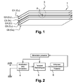
- the printed circuit 1 comprises a support or multilayer substrate on which are routed the tracks of the circuit and arranged the various electronic components (not shown).
- a substrate or PCB coming from the English terminology "Printed Circuit Board” comprises at least two outer conductive layers, for example Copper, composed of an upper layer C1 and a lower layer C6. They are electrically insulated from each other and with the other layers of the printed circuit by intermediate insulating layers (not shown), for example made of epoxy material.
- the printed circuit is formed by four conductive layers C1, C2, C5 and C6. Conductive layers
- the internal thermocouple forming elements are not electrically insulated.
- a temperature monitoring circuit for detecting any exceeding of a predetermined temperature threshold.
- This threshold is preferably chosen as the temperature limit beyond which any point of the circuit can be damaged and caused a malfunction of the circuit.
- the monitoring circuit is formed by the addition of two additional metal layers C3 and C4 constituting a thermoelectric pair at the printed circuit to create a Peltier / Seebeck cell placed closest to all the components of the printed circuit, called still electronic card.
- These two conductive layers are composed for example of a nickel layer and a chromium layer and form a thermocouple through the presence of two junctions 2 made between these two layers.
- thermocouple This has the effect of allowing instantaneous knowledge of the highest surface temperature of the printed circuit and this even at very high temperatures depending on the thermocouple used. Thus any heating defined as excessive will be detected and treated by a processing unit for converting thermal energy into electrical energy, which will be detailed later in connection with the figure 2 .
- the monitoring circuit is based on the measurement of the electromotive force 3 generated by the temperature variation in the inner conductive layers C3 and C4 and on correlation means between the measured electromotive force and the predetermined temperature threshold of overheating.
- the inner conductive layers were chosen as the middle layers C3 and C4, it is however possible to provide a monitoring circuit on the basis of two inner conductive layers arranged instead C2 and C3, in this case the PCB of the printed circuit is then formed by the layers C1, C4, C5 and C6, or alternatively, the monitoring circuit can group together the layers C4 and C5, the PCB then including the layers C1, C2, C3 and C6.
- the figure 2 represents a processing circuit related to the printed circuit monitoring circuit shown in FIG. figure 1 .
- the principle consists in converting the thermal energy generated by the thermocouple into electrical energy exploitable by the processing circuit.
- a monitoring circuit using a thermoelectric effect for example the Seebeck effect ( figures 1 and 3a, 3b ) or alternatively the Thomson effect, allows to collect an electromotive force (EMF) generated by a temperature variation (heating or cooling) and / or a temperature gradient in the thermocouple.
- EMF electromotive force
- This signal representative of the electromotive force is then exploitable by a processing circuit of the hardware or software type, which can then actuate suitable protection circuits.
- the measurement of the electromotive force 3 generated is defined by the potential difference between the two junctions of the inner conductive layers C3 and C4.
- the correlation means between the measured electromotive force and the overheating temperature threshold comprise a comparator 4 between the potential difference or thermocouple ⁇ Vth measured between the two junctions and a reference threshold Sref predefined representative of the difference in potential corresponding to a temperature variation between the normal operating temperature and the superheat temperature of the printed circuit.
- any heating defined as excessive will be detected at the output of the comparator 4 and transmitted to a processing unit 5.
- the main purpose of this processing unit is to control the actuation of a protection circuit 6 if the predetermined threshold is exceeded. overheating temperature.
- the principle of protection against a hot spot due to a source of heat maintained and linked to an electrical malfunction (short-circuit franc, short circuit aggravated due to a parasitic impedance, overload, etc.) can be treated of several ways, either by the power limitation (degraded mode strategy), or by the interruption of the energy supply by disconnection of the corresponding electrical power supplies 7 concerned. These two solutions are realized for example by means of electromechanical relays or semiconductors.
- the protection circuit comprises a limiter unit in order to be able to limit the electrical power supply power 7 of the circuit and according to a second variant the protection circuit comprises a circuit breaker unit in order to be able to disconnect the power supply 7 from the power supply. circuit.
- the protection circuit may be a combination of the two previous variants, the limiter unit being activated following the exceeding of a first threshold and the circuit breaker unit being activated following the passing of a second defined threshold greater than the first threshold.
- the first embodiment described above is therefore based on the use of a single link providing the thermocouple function which monitors the most extreme point thermally on the PCB.
- a simple processing unit with a similarly simple processing strategy, ie limiting or cutting off the power supply for the entire printed circuit, as well as a printed circuit without specific routing, ie thermocouple produced by means of raw layers. This has the further effect of reducing the cost of implementation while ensuring high reliability of operation.
- the inner conductive layers form a nickel / chromium thermocouple having a Peltier coefficient of 68 ⁇ V / ° Celsius.
- a circuit operating reference temperature set at 85 ° C. and a tolerance threshold of 200 ° C. ie a temperature of a hot point set at 285 ° C.
- the use for example of a low offset amplifier comparator to detect a voltage difference of 14 mV makes it possible to detect any temperature variations at any point of the printed circuit exceeding 200 ° C.
- the detection threshold is adjusted by the processing unit according to the protection strategies that meet the constraints to be satisfied.
- the Figures 3a and 3b represent a printed circuit equipped with a temperature monitoring circuit according to a second embodiment of the present invention.
- the figure 3a is a partial view showing only the upper and inner layers of the printed circuit so as to clearly show the routing applied to the monitoring circuit.
- the figure 3b represents the printed circuit as a whole on which are visible the junctions between the inner conductive layers forming the different thermocouples.
- the upper part of the PCB is represented. It comprises at least one layer, in this example two layers C1 and C2, as well as the inner conductive layers C3 and C4 of the monitoring circuit.
- the inner conductive layers C3 and C4 are divided so that several connections perform the thermocouple functions ensuring the monitoring as many points, thermally extreme, as there are functions or groups of functions to monitor on the PCB.
- Each subdivision S1, S2,... SN thus forms a thermocouple for monitoring the temperature of a function or group of functions of the PCB by measuring the electromotive force (FEM1, FEM2, ..., FEMN). generated between the thermocouple and the corresponding function or group of functions.
- thermoelectric junctions J1, J2,..., JN between each of the subdivisions S1, S2,..., SN of the two inner conductive layers C3 and C4 producing the different thermocouples.
- Each of these junctions is connected via links L1, L2,..., LN with an integrated processing unit on the PCB so as to be able to control a protection circuit corresponding to the function or group of defective functions.
- the figure 4 represents the processing circuit related to the printed circuit according to the second embodiment presented to the Figures 3a and 3b .
- Each link L1, L2,..., LN provides a potential difference representative of the hottest thermal point of the corresponding subdivision and therefore of the corresponding function or group of functions, which is compared, through comparators 41, 42, ..., 4n provided for this purpose, at a voltage representative of the operating tolerance threshold of the printed circuit.
- the results of the various comparisons made are processed in a processing unit consisting in determining which functions or group of functions must be protected and in respectively controlling the protection circuits related to each function or group of defective functions.
- the protection circuits 61, 62,..., 6n may be according to a first variant of the power limiting units or according to a second variant of the circuit breaker units to cut off the supply supplied to the corresponding function or group of functions.
- the protection circuit can be a combination of the two previous variants, the limiter unit being activated following the exceeding of a first threshold and the breaker unit being activated following the passing of a second defined threshold greater than the first threshold.
- the second embodiment described above in relation to the Figures 3a-3b and 4 is therefore based on the use of several links that perform the thermocouple functions ensuring the monitoring of as many points, thermally extreme, that there are functions or groups of functions to monitor on the PCB.
- Such a solution has the particular advantage of being able to locate and protect the defective function (s) while leaving the other operational functions active.
- the figure 5 represents a basic thermoelectric circuit for exploiting the thermoelectric effect of Seebeck as has been done in the context of the first two embodiments detailed above.
- the Seebeck coefficient is expressed in V.K-1, or more generally in ⁇ V.K-1 in view of the values of this coefficient in the usual materials.
- the printed circuit monitoring circuit comprises a single inner conductive layer traversed by an electric current and a device for measuring a thermal flux gradient between two points of the inner conductive layer.
- This monitoring circuit is based on the principle of the thermoelectric effect of Thomson represented by means of a schematic diagram at the figure 6 .
- the fundamental difference between the Seebeck and Peltier effects used in the context of the first two embodiments and the Thomson effect used in the context of this third embodiment is that the latter exists for a single material, ie a single additional conductive layer. being sufficient, and therefore does not require the presence of a junction.
- the Thomson effect is highlighted when a temperature gradient T and an electric current I are present simultaneously through a conductive material. There is then generation or heat absorption Q in each segment of material taken individually.
- This inner conductive layer may for example be made of copper as the layers forming the PCB.
- thermocouples there are several different types. All are used for a precise temperature range of a few degrees to a few thousand degrees.
- the electrical signals of these thermal detectors are of the order of microvolt to millivolt.
- the signals are processed by electronic modules integrating a function adapted to the thermocouple. The advantage of using such a thermocouple is its reliability, its small size and its ease of implementation.
Abstract
Description
L'invention concerne de manière générale un système de protection électrique contre la surchauffe d'un circuit électronique, et plus particulièrement, un système de détection d'une telle surchauffe. Cette invention est applicable dans le cadre de la protection électrique et contre les départs d'incendie provoqués par une dérive fonctionnelle de tout ou partie d'un équipement comprenant un circuit électronique et faisant intervenir une énergie (électrique, thermique, magnétique, chimique...).The invention generally relates to an electrical protection system against the overheating of an electronic circuit, and more particularly, a system for detecting such overheating. This invention is applicable in the context of electrical protection and against fire starts caused by a functional drift of all or part of an equipment comprising an electronic circuit and involving an energy (electrical, thermal, magnetic, chemical .. .).
En particulier, la présente invention a pour but de prévenir les départs d'incendies provoqués par la surchauffe des éléments ou composants constituant une carte électronique ou circuit imprimé. Les départs d'incendie concernés sont essentiellement ceux liés à une inflammation par flamme ou à l'atteinte du point d'auto inflammation d'un matériau constituant un équipement en contact avec une source de chaleur maintenue, ou en raison d'un disfonctionnement lié à un court-circuit franc ou aggravé, à une surcharge électrique...In particular, the present invention aims to prevent fire starts caused by overheating elements or components constituting an electronic card or printed circuit. The fire departures concerned are essentially those related to ignition by flame or reaching the self-ignition point of a material constituting equipment in contact with a heat source maintained, or due to a malfunction related to to a short circuit frank or aggravated, to an electric overload ...
Il est connu dans l'art antérieur de nombreux systèmes de protection contre la surchauffe de circuit électronique. En particulier, le document
Il est également connu, en particulier du document
Il est encore connu, en particulier du document
Toutes ces solutions de l'art antérieur préconisent une protection d'une carte électronique par surveillance du comportement thermique, laquelle surveillance de l'ensemble d'une carte électronique d'un point de vue thermique nécessite la surveillance du comportement thermique de chaque composant ou élément posé sur le circuit imprimé. Pour cela les solutions de mesure de température existantes exposées en relation avec les documents de l'art antérieur, nécessitent une implantation des circuits de surveillance à proximité de chaque composant de la carte électronique. De telles solutions impactes de façon significative la conception d'une carte électronique avec de nombreux inconvénients parmi lesquels un plus grand encombrement du circuit intégré ou de la carte imprimée en termes de surface, de poids et de volume, ainsi qu'une consommation électrique accrue, ce qui peut s'avérer très dommageable notamment pour les systèmes embarqués, une sûreté de fonctionnement et une fiabilité de détection incertaine dans la mesure où les disfonctionnements peuvent endommagés les circuits de test eux-mêmes, une complexité accrue d'interprétation des mesures et d'unité de traitement et bien entendu une répercussion importante sur le coût de fabrication d'un tel système intégré de protection contre les variations de température.All these solutions of the prior art recommend protection of an electronic card by monitoring the thermal behavior, which monitoring of the whole of an electronic card from a thermal point of view requires the monitoring of the thermal behavior of each component or element placed on the circuit board. For this, the existing temperature measurement solutions exposed in relation to the documents of the prior art, require implantation of the monitoring circuits near each component of the electronic card. Such solutions have a significant impact on the design of an electronic card with many disadvantages, including greater congestion of the integrated circuit or the printed circuit board in terms of area, weight and volume, as well as increased power consumption. This can be very damaging, especially for embedded systems, with unreliable operational reliability and detection reliability, since malfunctions can damage the test circuits themselves, increased complexity in the interpretation of measurements, and processing unit and of course a significant impact on the manufacturing cost of such an integrated system for protection against temperature variations.
Un but de la présente invention est de répondre aux inconvénients mentionnés ci-dessus en fournissant un circuit imprimé muni d'un dispositif de détection d'une surchauffe des éléments constituant le circuit, ce dispositif de détection devant être simple et fiable.An object of the present invention is to meet the drawbacks mentioned above by providing a printed circuit provided with a device for detecting overheating of the elements constituting the circuit, this detection device must be simple and reliable.
Dans ce but, un premier aspect de la présente invention concerne un circuit imprimé comprenant un support formé par au moins deux couches externes composées d'une couche supérieure et d'une couche inférieure, une pluralité de composants électroniques agencés sur le support, un circuit de surveillance de la température du circuit imprimé pour détecter un dépassement d'un seuil prédéterminé de température de surchauffe du circuit imprimé, caractérisé en ce que le circuit de surveillance comprend au moins une couche conductrice intérieure disposée entre les couches externes et un dispositif de mesure de la force électromotrice générée par une variation de température dans ladite au moins une couche conductrice intérieure et des moyens de corrélation entre la force électromotrice mesurée et le seuil prédéterminé de température de surchauffe.For this purpose, a first aspect of the present invention relates to a printed circuit comprising a support formed by at least two outer layers composed of an upper layer and a lower layer, a plurality of electronic components arranged on the support, a circuit for monitoring the temperature of the printed circuit for detecting an overshoot of a predetermined temperature threshold of overheating of the printed circuit, characterized in that the monitoring circuit comprises at least one inner conductive layer disposed between the outer layers and a measuring device electromotive force generated by a temperature variation in said at least one inner conductive layer and correlation means between the measured electromotive force and the predetermined temperature threshold of overheating.
L'adjonction d'au moins une couche métallique supplémentaire à l'intérieur du circuit imprimé constitue un thermocouple placé au plus près des composants du circuit ayant pour effet de permettre de connaître de façon instantanée la température la plus élevée en surface du circuit imprimé et cela même à des températures très élevées.The addition of at least one additional metal layer inside the printed circuit constitutes a thermocouple placed as close as possible to the components of the circuit having the effect of making it possible to know instantaneously the highest temperature at the surface of the printed circuit and this even at very high temperatures.
Selon un premier mode de réalisation avantageux, le circuit de surveillance comprend deux couches conductrices intérieures reliées par au moins deux jonctions et formant un thermocouple et en ce que le dispositif de mesure de la force électromotrice est un dispositif de mesure d'une différence de potentiel entre les deux jonctions. Une telle solution présente l'avantage de pouvoir choisir facilement les propriétés du thermocouple, en particulier le domaine de température le plus efficace suivant les conditions d'utilisation et les propriétés du circuit imprimé.According to a first advantageous embodiment, the monitoring circuit comprises two inner conductive layers connected by at least two junctions and forming a thermocouple and in that the device for measuring the electromotive force is a device for measuring a potential difference. between the two junctions. Such a solution has the advantage of being able to easily choose the properties of the thermocouple, in particular the most effective temperature range according to the conditions of use and the properties of the printed circuit.
Selon une variante avantageuse, les moyens de corrélation comprennent un comparateur entre la différence de potentiel mesurée entre les deux jonctions et un seuil de tension prédéfini correspondant à la différence de potentiel calculée pour la température de surchauffe.According to an advantageous variant, the correlation means comprise a comparator between the potential difference measured between the two junctions and a predefined voltage threshold corresponding to the potential difference calculated for the superheating temperature.
Selon une autre variante avantageuse, le circuit imprimé comprend quatre couches externes isolées électriquement entre elles et avec les couches conductrices intérieures de manière à accroître la surface d'intégration disponible sur le circuit imprimé.According to another advantageous variant, the printed circuit comprises four outer layers electrically insulated from each other and with the inner conductive layers so as to increase the integration surface available on the printed circuit.
Selon une autre variante avantageuse, le thermocouple est une cellule de Peltier.According to another advantageous variant, the thermocouple is a Peltier cell.
Selon un autre mode de réalisation avantageux, le circuit de surveillance comprend une seule couche conductrice intérieure traversée par un courant électrique et le dispositif de mesure de la force électromotrice est un dispositif de mesure d'un gradient de flux thermique entre deux points de la couche conductrice intérieure. Une telle solution présente l'avantage de ne nécessiter qu'une seule couche additionnelle, ce qui rend sa réalisation moins complexe et moins coûteuse tout en réduisant l'épaisseur totale du circuit imprimé.According to another advantageous embodiment, the monitoring circuit comprises a single inner conductive layer traversed by an electric current and the device for measuring the electromotive force is a device for measuring a thermal flux gradient between two points of the layer. inner conductor. Such a solution has the advantage of requiring only one additional layer, which makes its implementation less complex and less expensive while reducing the total thickness of the printed circuit.
Selon une variante avantageuse selon l'un des deux modes précédents, le circuit imprimé comprend un circuit de protection actionné en cas de dépassement du seuil de température de surchauffe, ce circuit de protection comprenant une unité limiteur pour pouvoir limiter la puissance d'alimentation électrique du circuit.According to an advantageous variant according to one of the two preceding modes, the printed circuit comprises a protection circuit actuated in case of exceeding the overheating temperature threshold, this protection circuit comprising a limiter unit to be able to limit the power supply power. of the circuit.
Selon une autre variante avantageuse, le circuit imprimé comprend un circuit de protection actionné en cas de dépassement du seuil de température de surchauffe, ce circuit de protection comprenant une unité disjoncteur pour pouvoir déconnecter l'alimentation électrique du circuit. Une telle variante présente l'avantage de combiner un circuit de détection simple et fiable selon l'un des deux modes précédents avec un circuit de protection contre la surchauffe du circuit imprimé.According to another advantageous variant, the printed circuit comprises a protection circuit actuated in the event of exceeding the overheating temperature threshold, this protection circuit comprising a circuit breaker unit in order to be able to disconnect the power supply from the circuit. Such a variant has the advantage of combining a simple and reliable detection circuit according to one of the two preceding modes with a protection circuit against overheating of the printed circuit.
Selon un autre mode de réalisation, le support du circuit imprimé est subdivisé en plusieurs unités ou groupe d'unités fonctionnelles, et à chaque unité ou groupe d'unités fonctionnelles correspond un circuit de surveillance obtenu par subdivision des couches intérieures en un nombre correspondant de thermocouples. Ce mode de réalisation présente l'avantage de pouvoir détecter chaque unité ou groupe d'unités fonctionnelles défectueuses indépendamment. Avantageusement, chaque thermocouple est une cellule de Peltier.According to another embodiment, the support of the printed circuit is subdivided into several units or group of functional units, and each unit or group of functional units corresponds to a monitoring circuit obtained by subdivision of the inner layers into a number corresponding thermocouples. This embodiment has the advantage of being able to detect each unit or group of defective functional units independently. Advantageously, each thermocouple is a Peltier cell.
Selon une autre variante avantageuse, le circuit comprend un circuit de protection pour chaque unité ou groupe d'unités fonctionnelles, actionné en cas de dépassement du seuil de température de surchauffe de l'unité ou du groupe d'unités fonctionnelles correspondant. Cette variante présente l'avantage de permettre de protéger uniquement les unités ou groupe d'unités fonctionnelles défectueuses.According to another advantageous variant, the circuit comprises a protection circuit for each unit or group of functional units actuated in the event of exceeding the overheating temperature threshold of the corresponding unit or group of functional units. This variant has the advantage of only protecting the units or group of defective functional units.
Selon une autre variante avantageuse, le circuit de protection comprend une unité limiteur pour pouvoir limiter la puissance d'alimentation électrique de l'unité ou du groupe d'unités fonctionnelles correspondant.According to another advantageous variant, the protection circuit comprises a limiter unit in order to limit the power supply power of the corresponding unit or group of functional units.
Selon une autre variante avantageuse, le circuit de protection comprend une unité disjoncteur pour pouvoir déconnecter l'alimentation électrique de l'unité ou groupe d'unités fonctionnelles correspondant.According to another advantageous variant, the protection circuit comprises a circuit breaker unit in order to be able to disconnect the power supply from the corresponding unit or group of functional units.
D'autres caractéristiques et avantages de la présente invention apparaîtront plus clairement à la lecture de la description détaillée qui suit de modes de réalisation de l'invention donnés à titre d'exemples nullement limitatifs et illustrés par les dessins annexés, dans lesquels :
- la
figure 1 représente un circuit imprimé équipé d'un circuit de surveillance de la température selon un mode de réalisation préféré de la présente invention; - la
figure 2 représente un circuit de traitement lié au circuit de surveillance de lafigure 1 ; - les
figures 3a et 3b représentent un circuit imprimé équipé d'un circuit de surveillance de la température selon un autre mode de réalisation de la présente invention; - la
figure 4 représente un circuit de traitement lié au circuit de surveillance desfigures 3a et 3b ; - la
figure 5 représente un circuit thermoélectrique de base pour exploiter l'effet thermoélectrique de Seebeck; - la
figure 6 représente un schéma de principe de l'effet thermoélectrique de Thomson;
- the
figure 1 represents a printed circuit equipped with a temperature monitoring circuit according to a preferred embodiment of the present invention; - the
figure 2 represents a processing circuit related to the monitoring circuit of thefigure 1 ; - the
Figures 3a and 3b represent a printed circuit equipped with a temperature monitoring circuit according to another embodiment of the present invention; - the
figure 4 represents a processing circuit related to the monitoring circuit of theFigures 3a and 3b ; - the
figure 5 represents a basic thermoelectric circuit for exploiting the thermoelectric effect of Seebeck; - the
figure 6 represents a schematic diagram of Thomson's thermoelectric effect;
L'invention sera décrite ci-après uniquement à titre d'exemples non limitatifs en relation avec les
Le circuit imprimé 1 comprend un support ou substrat multicouche sur lequel sont routées les pistes du circuit et disposés les différents composants électroniques (non représentés). Un tel substrat ou PCB, venant de la terminologie anglaise "Printed Circuit Board", comprend au moins deux couches conductrices externes, par exemple en Cuivre, composées d'une couche supérieure C1 et d'une couche inférieure C6. Elles sont isolées électriquement entre elles et avec les autres couches du circuit imprimé par des couches isolantes intermédiaires (non représentées), par exemple en matériau époxy. De préférence, pour des raisons de capacité d'intégration, le circuit imprimé est formé par quatre couches conductrices C1, C2, C5 et C6. Les couches conductrices intérieures formant le thermocouple ne sont en revanche pas isolées électriquement.The printed
Dans le but de prévenir tout disfonctionnement du circuit imprimé lié à la surchauffe des éléments ou composants constituant le circuit imprimé, il est prévu de munir ce dernier d'un circuit de surveillance de la température pour détecter tout dépassement d'un seuil prédéterminé de température dit de "surchauffe" du circuit imprimé. Ce seuil est choisi de préférence comme la limite de température au-delà de laquelle tout point du circuit peut être endommagé et entraîné un disfonctionnement du circuit.In order to prevent any malfunction of the printed circuit related to the overheating of the elements or components constituting the printed circuit, it is intended to provide the latter with a temperature monitoring circuit for detecting any exceeding of a predetermined temperature threshold. said of "overheating" of the printed circuit. This threshold is preferably chosen as the temperature limit beyond which any point of the circuit can be damaged and caused a malfunction of the circuit.
Selon le premier mode de réalisation présenté en liaison avec la
Cela a pour effet de permettre de connaître de façon instantanée la température la plus élevée en surface du circuit imprimé et cela même à des températures très élevées suivant le thermocouple utilisé. Ainsi tout échauffement définit comme excessif sera détecté et traité par une unité de traitement permettant de convertir l'énergie thermique en énergie électrique, qui sera détaillée plus loin en liaison avec la
Pour cela, le circuit de surveillance est basé sur la mesure de la force électromotrice 3 générée par la variation de température dans les couches conductrices intérieures C3 et C4 et sur des moyens de corrélation entre la force électromotrice mesurée et le seuil prédéterminé de température de surchauffe. Dans cet exemple représenté à la
La
Ce signal représentatif de la force électromotrice est alors exploitable par un circuit de traitement de type matériel ou logiciel, pouvant ensuite actionner des circuits de protections adaptés.This signal representative of the electromotive force is then exploitable by a processing circuit of the hardware or software type, which can then actuate suitable protection circuits.
Dans le cadre du premier mode de réalisation, présenté en relation la
Ainsi tout échauffement définit comme excessif sera détecté à la sortie du comparateur 4 et transmis à une unité de traitement 5. Cette unité de traitement a pour but principal de commander l'actionnement d'un circuit de protection 6 en cas de dépassement du seuil prédéfini de température de surchauffe. Le principe de la protection contre un point chaud avéré, du à une source de chaleur entretenue et lié à un dysfonctionnement électrique (court-circuit franc, court-circuit aggravé dû à une impédance parasite, surcharge, etc.) peut être traité de plusieurs façons, soit par la limitation de puissance (stratégie de mode dégradé), soit par la coupure de l'arrivée d'énergie par déconnexion des alimentations 7 électriques correspondantes concernées. Ces deux solutions sont réalisées par exemple au moyen de relais électromécaniques ou de semi-conducteurs. Ainsi selon une première variante de réalisation, le circuit de protection comprend une unité limiteur pour pouvoir limiter la puissance d'alimentation électrique 7 du circuit et selon une deuxième variante le circuit de protection comprend une unité disjoncteur pour pouvoir déconnecter l'alimentation électrique 7 du circuit. Alternativement, le circuit de protection peut être une combinaison des deux variantes précédentes, l'unité limiteur étant activée suite au dépassement d'un premier seuil et l'unité disjoncteur étant activée suite au dépassement d'un deuxième seuil défini supérieur au premier seuil.Thus any heating defined as excessive will be detected at the output of the
Le premier mode de réalisation exposé ci-dessus est donc basé sur l'utilisation d'une seule liaison réalisant la fonction thermocouple qui assure la surveillance du point le plus extrême thermiquement sur le PCB. Une telle solution présente un certain nombre d'avantages et permet en particulier l'utilisation d'une unité de traitement simple avec une stratégie de traitement également simple, i.e. limitation ou coupure de l'alimentation pour l'ensemble du circuit imprimé, ainsi qu'un circuit imprimé sans routage spécifique, i.e. thermocouple réalisé au moyen de couches brutes. Cela a en outre pour effet de réduite le coût de réalisation tout en assurant une grande fiabilité de fonctionnement.The first embodiment described above is therefore based on the use of a single link providing the thermocouple function which monitors the most extreme point thermally on the PCB. Such a solution has a certain number of advantages and makes it possible in particular to use a simple processing unit with a similarly simple processing strategy, ie limiting or cutting off the power supply for the entire printed circuit, as well as a printed circuit without specific routing, ie thermocouple produced by means of raw layers. This has the further effect of reducing the cost of implementation while ensuring high reliability of operation.
A titre d'exemple avantageux selon le premier mode de réalisation, les couches conductrices intérieures forment un thermocouple Nickel / Chrome présentant un coefficient de Peltier de 68µV / °Celsius. Ainsi pour une température de référence de fonctionnement du circuit fixée à 85 °C et un seuil de tolérance de 200°C, soit une température d'un point chaud fixée à 285°C, la différence de tension due à l'élévation de température pour un tel point chaud est de 200 * 68 = 13.6 mV.As an advantageous example according to the first embodiment, the inner conductive layers form a nickel / chromium thermocouple having a Peltier coefficient of 68 μV / ° Celsius. Thus, for a circuit operating reference temperature set at 85 ° C. and a tolerance threshold of 200 ° C., ie a temperature of a hot point set at 285 ° C., the difference in voltage due to the rise in temperature for such a hot spot is 200 * 68 = 13.6 mV.
En conséquence, l'utilisation par exemple d'un comparateur amplificateur à faible offset pour détecter une différence de tension de 14 mV permet de détecter toutes variations de température en tout point du circuit imprimé dépassant 200°C. Le seuil de détection est ajusté par l'unité de traitement selon les stratégies de protection répondant aux contraintes à satisfaire.Consequently, the use for example of a low offset amplifier comparator to detect a voltage difference of 14 mV makes it possible to detect any temperature variations at any point of the printed circuit exceeding 200 ° C. The detection threshold is adjusted by the processing unit according to the protection strategies that meet the constraints to be satisfied.
Les
Considérant la
Considérant maintenant la
La
Le deuxième mode de réalisation exposé ci-dessus en relation avec les
La
Deux matériaux conducteurs de natures différentes a et b sont reliés par deux jonctions en X et W. Dans le cas de l'effet Seebeck, une différence de température dT est appliquée entre W et X, ce qui entraîne l'apparition d'une différence de potentiel dV entre Y et Z. En circuit ouvert, le coefficient Seebeck Sab du couple de matériaux, ou pouvoir thermoélectrique est défini par : 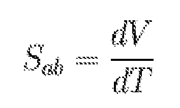
Le coefficient Seebeck s'exprime en V.K-1, ou plus généralement en µV.K-1 au vu des valeurs de ce coefficient dans les matériaux usuels.The Seebeck coefficient is expressed in V.K-1, or more generally in μV.K-1 in view of the values of this coefficient in the usual materials.
Selon un troisième mode de réalisation le circuit de surveillance du circuit imprimé comprend une seule couche conductrice intérieure traversée par un courant électrique et un dispositif de mesure d'un gradient de flux thermique entre deux points de la couche conductrice intérieure. Ce circuit de surveillance est basé sur le principe de l'effet thermoélectrique de Thomson représenté au moyen d'un schéma de principe à la
La différence fondamentale entre les effets Seebeck et Peltier utilisés dans le cadre des deux premiers modes de réalisation et l'effet Thomson utilisé dans le cadre de ce troisième mode de réalisation est que ce dernier existe pour un seul matériau, i.e. une seule couche conductrice additionnelle étant suffisante, et ne nécessite donc pas la présence d'une jonction. L'effet Thomson est mis en évidence lorsque sont présents simultanément un gradient de température T et un courant électrique I à travers un matériau conducteur. Il y a alors génération ou absorption de chaleur Q dans chaque segment de matériau pris individuellement. Le gradient de flux thermique au sein du matériau est alors donné par : 
où x est la coordonnée spatiale et τ est le coefficient Thomson du matériau.The fundamental difference between the Seebeck and Peltier effects used in the context of the first two embodiments and the Thomson effect used in the context of this third embodiment is that the latter exists for a single material, ie a single additional conductive layer. being sufficient, and therefore does not require the presence of a junction. The Thomson effect is highlighted when a temperature gradient T and an electric current I are present simultaneously through a conductive material. There is then generation or heat absorption Q in each segment of material taken individually. The thermal flux gradient within the material is then given by:
where x is the spatial coordinate and τ is the Thomson coefficient of the material.
Ainsi, dans le cas de la mesure de gradient de température (Effet Thomson) une seule couche conductrice intérieure au PCB et parcourue par un courant électrique injecté, est nécessaire pour permettre de connaître de façon instantanée une différence de température en surface du circuit imprimé, même à des températures très élevées. Cette couche conductrice intérieure pourra par exemple être en Cuivre comme les couches formant le PCB.Thus, in the case of the temperature gradient measurement (Thomson Effect) a single conductive layer inside the PCB and traversed by an injected electric current, is necessary to make it possible to know instantaneously a surface temperature difference of the printed circuit, even at very high temperatures. This inner conductive layer may for example be made of copper as the layers forming the PCB.
On notera encore en liaison avec ce troisième mode de réalisation que l'on pourra utiliser de la même manière que dans le cadre des premier et deuxième modes de réalisation sus-décrits, un (cf.
On comprendra que diverses modifications et / ou améliorations évidentes pour l'homme du métier peuvent être apportées aux différentes modes de réalisation de l'invention décrits dans la présente description sans sortir du cadre de l'invention défini par les revendications annexées. En particulier, on comprendra qu'il existe plusieurs types de thermocouples différents. Tous sont utilisés pour une gamme précise de température de quelques degrés à quelques milliers de degrés. Les signaux électriques de ces détecteurs thermiques sont de l'ordre du microvolt au millivolt. Les signaux sont traités par des modules électroniques intégrants une fonction adaptée au thermocouple. L'avantage de l'utilisation d'un tel thermocouple est sa fiabilité, son encombrement réduit et sa facilité de mise en oeuvre.It will be understood that various modifications and / or improvements obvious to those skilled in the art can be made to the various embodiments of the invention described in the present description without departing from the scope of the invention defined by the appended claims. In particular, it will be understood that there are several different types of thermocouples. All are used for a precise temperature range of a few degrees to a few thousand degrees. The electrical signals of these thermal detectors are of the order of microvolt to millivolt. The signals are processed by electronic modules integrating a function adapted to the thermocouple. The advantage of using such a thermocouple is its reliability, its small size and its ease of implementation.
Claims (13)
Priority Applications (1)
| Application Number | Priority Date | Filing Date | Title |
|---|---|---|---|
| EP08152224A EP2099264A1 (en) | 2008-03-03 | 2008-03-03 | Printed circuit board with thermocouple |
Applications Claiming Priority (1)
| Application Number | Priority Date | Filing Date | Title |
|---|---|---|---|
| EP08152224A EP2099264A1 (en) | 2008-03-03 | 2008-03-03 | Printed circuit board with thermocouple |
Publications (1)
| Publication Number | Publication Date |
|---|---|
| EP2099264A1 true EP2099264A1 (en) | 2009-09-09 |
Family
ID=39577665
Family Applications (1)
| Application Number | Title | Priority Date | Filing Date |
|---|---|---|---|
| EP08152224A Ceased EP2099264A1 (en) | 2008-03-03 | 2008-03-03 | Printed circuit board with thermocouple |
Country Status (1)
| Country | Link |
|---|---|
| EP (1) | EP2099264A1 (en) |
Cited By (3)
| Publication number | Priority date | Publication date | Assignee | Title |
|---|---|---|---|---|
| US9516790B2 (en) | 2013-04-09 | 2016-12-06 | Harman Becker Automotive Systems Gmbh | Thermoelectric cooler/heater integrated in printed circuit board |
| GB2571524A (en) * | 2018-02-28 | 2019-09-04 | Continental Automotive Gmbh | Electric device comprising a printed circuit board and method for determining local temperatures at different measurement points of the printed circuit boar |
| CN117082722A (en) * | 2023-09-19 | 2023-11-17 | 荣耀终端有限公司 | PCB (printed circuit board), PCB temperature measuring circuit and electronic equipment |
Citations (8)
| Publication number | Priority date | Publication date | Assignee | Title |
|---|---|---|---|---|
| US5180440A (en) * | 1988-11-23 | 1993-01-19 | Pace Incorporated | Printed circuit thermocouple arrangements for personnel training and equipment evaluation purposes |
| DE4123870A1 (en) * | 1991-07-18 | 1993-01-21 | Elli Tutsch | Monitoring electronic assemblies with components on base carrier - measuring temp. at widely different points on carrier from variation in voltage applied to thermo-wires to detect burn through of components or conductor paths in module |
| US5962934A (en) * | 1996-10-18 | 1999-10-05 | Temic Telefunken Microelectronic Gmbh | Arrangement for electrical power supply |
| US20020139575A1 (en) * | 2001-03-30 | 2002-10-03 | Arjang Fartash | Printed circuit board with embedded thermocouple junctions |
| US20040159904A1 (en) | 2003-02-13 | 2004-08-19 | International Business Machines Corporation | Thermally aware integrated circuit |
| US20040179576A1 (en) | 2003-03-11 | 2004-09-16 | Bowden Scott J. | Failsafe mechanism for preventing an integrated circuit from overheating |
| US20070090870A1 (en) | 2005-10-21 | 2007-04-26 | Samsung Electronics Co., Ltd. | Integrated circuit and method for automatically tuning process and temperature variations |
| EP1811819A1 (en) * | 2006-01-19 | 2007-07-25 | Siemens Aktiengesellschaft | Circuit board |
-
2008
- 2008-03-03 EP EP08152224A patent/EP2099264A1/en not_active Ceased
Patent Citations (8)
| Publication number | Priority date | Publication date | Assignee | Title |
|---|---|---|---|---|
| US5180440A (en) * | 1988-11-23 | 1993-01-19 | Pace Incorporated | Printed circuit thermocouple arrangements for personnel training and equipment evaluation purposes |
| DE4123870A1 (en) * | 1991-07-18 | 1993-01-21 | Elli Tutsch | Monitoring electronic assemblies with components on base carrier - measuring temp. at widely different points on carrier from variation in voltage applied to thermo-wires to detect burn through of components or conductor paths in module |
| US5962934A (en) * | 1996-10-18 | 1999-10-05 | Temic Telefunken Microelectronic Gmbh | Arrangement for electrical power supply |
| US20020139575A1 (en) * | 2001-03-30 | 2002-10-03 | Arjang Fartash | Printed circuit board with embedded thermocouple junctions |
| US20040159904A1 (en) | 2003-02-13 | 2004-08-19 | International Business Machines Corporation | Thermally aware integrated circuit |
| US20040179576A1 (en) | 2003-03-11 | 2004-09-16 | Bowden Scott J. | Failsafe mechanism for preventing an integrated circuit from overheating |
| US20070090870A1 (en) | 2005-10-21 | 2007-04-26 | Samsung Electronics Co., Ltd. | Integrated circuit and method for automatically tuning process and temperature variations |
| EP1811819A1 (en) * | 2006-01-19 | 2007-07-25 | Siemens Aktiengesellschaft | Circuit board |
Non-Patent Citations (1)
| Title |
|---|
| "Thermoelectricity: Theory, Thermometry, Tool, ASTM STP Issue 852", 1 January 1985, ASTM INTERNATIONAL, ISBN: 978-0-80-310409-9, article DANIEL D POLLOCK: "Thermoelectricity: Theory, Thermometry, Tool, ASTM STP Issue 852", pages: 113 - 114, XP055087750 * |
Cited By (3)
| Publication number | Priority date | Publication date | Assignee | Title |
|---|---|---|---|---|
| US9516790B2 (en) | 2013-04-09 | 2016-12-06 | Harman Becker Automotive Systems Gmbh | Thermoelectric cooler/heater integrated in printed circuit board |
| GB2571524A (en) * | 2018-02-28 | 2019-09-04 | Continental Automotive Gmbh | Electric device comprising a printed circuit board and method for determining local temperatures at different measurement points of the printed circuit boar |
| CN117082722A (en) * | 2023-09-19 | 2023-11-17 | 荣耀终端有限公司 | PCB (printed circuit board), PCB temperature measuring circuit and electronic equipment |
Similar Documents
| Publication | Publication Date | Title |
|---|---|---|
| EP1715315B1 (en) | Bolometric detector, device for the detection of submillimetric and millimetric electromagnetic waves using said detector | |
| EP2246677B1 (en) | Bolometric detector of electromagnetic radiation from the infrared to the terahertz spectral domain and detector array device comprising said detectors. | |
| EP2267772B1 (en) | Circuit for detecting thinning of the substrate of an integrated circuit chip | |
| EP2071309B1 (en) | Device for detecting infrared radiation comprising an imaging resistive bolometer, system comprising an array of such bolometers and method of reading an imaging bolometer integrated in such a system | |
| EP2689221B1 (en) | Differential temperature sensor and its cmos/bicmos technology capabilities | |
| FR2986356A1 (en) | DEVICE FOR PROTECTING AN INTEGRATED CIRCUIT AGAINST REAR-SIDE ATTACKS | |
| EP2602598A1 (en) | Bolometric detector for electromagnetic radiation in the terahertz spectral band and detector matrix comprising such detectors | |
| EP3627275B1 (en) | Electronic device capable of forming a temperature sensor or a current source for providing a current independently of the temperature | |
| EP2700922A1 (en) | Bolometric detector of electromagnetic radiation in the terahertz range and matrix detection device comprising such detectors | |
| EP3262403B1 (en) | Moisture sensor with thermal module | |
| EP2740152A1 (en) | Device for localizing hot spots with heat flow meters | |
| EP3046147B1 (en) | Electronic chip provided with a protective device with phase change material, method for detecting an attack on the chip and method for manufacturing said chip | |
| EP2099264A1 (en) | Printed circuit board with thermocouple | |
| FR2843234A1 (en) | MINIATURE CONNECTOR WITH ON-BOARD ELECTRONICS FOR THERMOCOUPLE | |
| EP2602599A1 (en) | Bolometric detector for detecting Teraherz electromagnetic radiation | |
| FR3016217A1 (en) | DEVICE AND METHOD FOR DETECTING HEATING OF A BATTERY PACKAGE | |
| WO2018167434A1 (en) | Radiation sensor with anti-glare protection | |
| EP1692475B1 (en) | Improved radiant-energy-measuring device with two positions | |
| EP2666000B1 (en) | Device for measuring or determining the time derivative of a heat flow exchanged between a first medium and a second medium | |
| EP3314753B1 (en) | Method for controlling the quality of a photovoltaic device, and associated inspection device | |
| FR2944876A1 (en) | Junction temperature junction quantifying method for e.g. diode, involves measuring temperature of environment of electric/electronic component by temperature sensors, where environment is constituted of given temperature case | |
| FR2846161A1 (en) | IC engine exhaust gas linear probe circuit assembly has additional component such as transistor to detect abnormal potential | |
| FR2941046A1 (en) | DEVICE FOR DETECTING ELECTROMAGNETIC RADIATION | |
| EP2659526B1 (en) | Modular adjustable thermoelectric device, and method for operating said thermoelectric device | |
| EP3570200B1 (en) | Electronic chip |
Legal Events
| Date | Code | Title | Description |
|---|---|---|---|
| PUAI | Public reference made under article 153(3) epc to a published international application that has entered the european phase |
Free format text: ORIGINAL CODE: 0009012 |
|
| AK | Designated contracting states |
Kind code of ref document: A1 Designated state(s): AT BE BG CH CY CZ DE DK EE ES FI FR GB GR HR HU IE IS IT LI LT LU LV MC MT NL NO PL PT RO SE SI SK TR |
|
| AX | Request for extension of the european patent |
Extension state: AL BA MK RS |
|
| 17P | Request for examination filed |
Effective date: 20100226 |
|
| AKX | Designation fees paid |
Designated state(s): AT BE BG CH CY CZ DE DK EE ES FI FR GB GR HR HU IE IS IT LI LT LU LV MC MT NL NO PL PT RO SE SI SK TR |
|
| 17Q | First examination report despatched |
Effective date: 20110708 |
|
| STAA | Information on the status of an ep patent application or granted ep patent |
Free format text: STATUS: THE APPLICATION HAS BEEN REFUSED |
|
| 18R | Application refused |
Effective date: 20131210 |