EP2105162A2 - Method and apparatus for defrosting a defibrillation electrode - Google Patents
Method and apparatus for defrosting a defibrillation electrode Download PDFInfo
- Publication number
- EP2105162A2 EP2105162A2 EP09156315A EP09156315A EP2105162A2 EP 2105162 A2 EP2105162 A2 EP 2105162A2 EP 09156315 A EP09156315 A EP 09156315A EP 09156315 A EP09156315 A EP 09156315A EP 2105162 A2 EP2105162 A2 EP 2105162A2
- Authority
- EP
- European Patent Office
- Prior art keywords
- defibrillator
- electrode
- electrodes
- controller
- conductive interface
- Prior art date
- Legal status (The legal status is an assumption and is not a legal conclusion. Google has not performed a legal analysis and makes no representation as to the accuracy of the status listed.)
- Granted
Links
Images


Classifications
-
- A—HUMAN NECESSITIES
- A61—MEDICAL OR VETERINARY SCIENCE; HYGIENE
- A61N—ELECTROTHERAPY; MAGNETOTHERAPY; RADIATION THERAPY; ULTRASOUND THERAPY
- A61N1/00—Electrotherapy; Circuits therefor
- A61N1/02—Details
- A61N1/04—Electrodes
- A61N1/0404—Electrodes for external use
- A61N1/0408—Use-related aspects
- A61N1/046—Specially adapted for shock therapy, e.g. defibrillation
-
- A—HUMAN NECESSITIES
- A61—MEDICAL OR VETERINARY SCIENCE; HYGIENE
- A61N—ELECTROTHERAPY; MAGNETOTHERAPY; RADIATION THERAPY; ULTRASOUND THERAPY
- A61N1/00—Electrotherapy; Circuits therefor
- A61N1/18—Applying electric currents by contact electrodes
- A61N1/32—Applying electric currents by contact electrodes alternating or intermittent currents
- A61N1/38—Applying electric currents by contact electrodes alternating or intermittent currents for producing shock effects
- A61N1/39—Heart defibrillators
- A61N1/3904—External heart defibrillators [EHD]
Definitions
- the present invention relates to methods and devices for resuscitating a patient. More particularly, the present invention relates to electric defibrillators and thawing frozen defibrillation electrodes used with electric defibrillators.
- Patient conditions that may require resuscitation include, but are not limited to, cardiac arrest, bradycardia, tachycardia, ventricular fibrillation and respiratory arrest.
- One example of a technique for resuscitating a patient is to use an electric defibrillator to apply electrical energy to the patient.
- An electric defibrillator typically includes a power source and at least two defibrillation electrodes that provide a connection with the skin of a patient for electricity to be administered to the patient.
- defibrillation electrodes are disposed upon the chest region of a patient such that electrical energy can be administered to the patient.
- AEDs automated external defibrillators
- Cardiac Science's Powerheart ® Medtronic's LIFEPAK ®
- Defibtech's Lifeline TM Phillips' HeartStart TM
- Zoll's AED Plus ® examples of such AEDs include: Cardiac Science's Powerheart ® , Medtronic's LIFEPAK ® , Defibtech's Lifeline TM , Phillips' HeartStart TM , and Zoll's AED Plus ® .
- AEDs are continuously operational and ready for use on a moment's notice. Any delay in the ability of a rescuer to use such a device in an emergency can mean the difference between life and death for a patient. One such delay may occur as a result of the defibrillation electrodes being frozen. Because AEDs are highly portable, they are often stored in automobiles or other unheated places. In cold weather, portions of the defibrillation electrodes may freeze. In order for a defibrillation electrode to properly deliver an appropriate electrical impulse as described, the electrode must not be frozen. In current practice, if an electrode is frozen, a rescuer must either replace the electrode with an unfrozen one, or use external means such as a heater to thaw the electrode. Often, in critical situations, a frozen electrode results in valuable time wasted and in the worst case may result in death to a patient.
- an automated external defibrillator with defrosting capabilities includes a portable housing containing a battery powered energy source and a controller.
- the embodiment also includes at least a pair of electrodes operably coupled to the housing.
- the electrodes are releasably attachable to an external portion of a patient in need of resuscitation.
- each of the electrodes includes a conductive interface medium having physical properties dependent upon a desired temperature range of about 32OF to 122OF.
- the controller is configured to selectively heat the conductive interface medium by applying a limited amount of electrical impulse from the energy source to raise the temperature of the conductive interface medium toward the desired range.
- an automated external defibrillator with defrosting capabilities includes a pair of preconnected electrodes including an outer hydrogel layer on each electrode having physical properties dependent upon a normal temperature range of about 32OF to 122OF. Also included is a housing having a battery powered energy source and a controller that selectively heats the hydrogel layer by applying a limited amount of electrical impulse to raise the temperature of the hydrogel layer to the normal range.
- a method of controlling the operating conditions of defibrillation electrodes of an automated external defibrillator includes providing a pair of electrodes releasably attachable with an external portion of a patient in need of resuscitation where each electrode has a conductive interface medium having physical properties dependent upon a desired temperature range of about 32OF to 122OF. The method also including automatically causing the automated external defibrillator to deliver a limited electrical impulse to the defibrillation electrodes so as to heat the defibrillation electrodes to the desired temperature range.
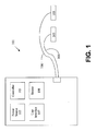
- Fig. 1 illustrates generally an example of an electric defibrillator 101.
- electric defibrillator 101 includes one or more power sources 102.
- power source 102 includes one or more batteries.
- power source 102 also includes one or more capacitors.
- power source 102 is adapted to provide energy sufficient to provide an electrical impulse capable of stimulating a heart.
- defibrillator 101 includes controller 103. Controller 103 is adapted to initiate, adjust, and/or monitor functions of defibrillator 101. In various embodiments, controller 103 is adapted to initiate or adjust delivery of an electric impulse for purposes of providing electrical therapy to a patient.
- defibrillator 101 further includes user interface 107.
- User interface 107 is adapted to allow communication between a user and controller 103.
- user interface 107 is adapted to allow a user to program controller 103.
- defibrillator 101 also includes at least one electrode 105.
- electrode 105 is connected to electrical conductor 106 such that electrode 105 is in electrical connection with power source 102.
- electrode 105 is adapted to be placed in contact with a patient and serve as a connection for delivery of electrical energy to a patient.
- at least two electrodes 105 are required so that an electrical connection is provided across the body of a patient such that a current may be driven through the body of a patient to stimulate the patient's heart.
- defibrillator 101 further includes at least one sensor 108. These sensors 108 are generally operably connected to controller 103. Sensor 108 may be adapted to determine conditions of components of defibrillator 101. In one embodiment, sensor 108 is adapted to determine a temperature of electrode 105. In one embodiment, sensor 108 is adapted to determine the amount of energy stored in power source 102. In various embodiments, sensor 108 is adapted to determine conditions of components of defibrillator 101. In one embodiment, sensor 108 is adapted to determine whether electrode 105 is frozen. In various embodiments, sensor 108 is adapted to determine conditions external to defibrillator 101. In some embodiments, sensor 108 may also be capable of detecting defibrillator movement or other events commonly occurring prior to defibrillation, such as movement of a defibrillator panel.
- electrode 105 is a defibrillation electrode adapted to apply an electric impulse to a patient. If electrode 105 is frozen, or very cold, it will likely not function properly to apply an electrical impulse to a patient. Therefore, a frozen electrode 105 must be defrosted quickly and efficiently so that electrode 105 will function effectively to apply an electrical impulse to a patient. More specifically, certain components of the electrode such as a hydrogel layer or other conductive interface medium can readily freeze when temperatures drop below a desired temperature range. The physical properties of the conductive interface medium often requires a desired, normal temperature range for operation to generally be about 32°F to 122°F. Such a range is needed for safe and reliable defibrillation operation. Consequently, the controller of the present invention is designed to selectively heat the conductive interface medium by applying a limited amount of electrical impulse from the energy source to raise the temperature of the conductive interface medium to the desired range.
- using the controller to selectively signal the electrical impulses or other means to warm and defrost the electrodes can be done in a variety of ways.
- a sensor 108 in the defibrillator may detect a freezing temperature in the proximity of the electrodes.
- a sensor that detects when the defibrillator is moved or opened can signal defrosting, as such actions will often occur just prior to defibrillation.
- Sending sensor data to the controller in this way will also ensure the defibrillator is ready for use at desired times. Additional signalling events may follow routine or automatic self testing operations by the defibrillator.
- the controller may be programmed with various safety features to recognize and prevent continuous or repetitive signalling data that might result in significant battery usage and drain. Such features ensure that the defibrillator will be sufficiently charged for proper use.
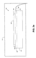
- Fig. 2a illustrates generally one example of a defibrillation electrode 201.
- Defibrillation electrode 201 includes a lead location 202 and a patient contact surface 203.
- patient surface 203 is adapted to be placed in contact with a patient in order to deliver electrical therapy to the patient.
- Lead location 202 is adapted to connect an electrode 201 to an electrical conductor 106.
- lead location 202 includes a lead 204 which may be made of a conductive material.
- Electrode 201 further includes base layer 205.
- base layer 205 is any non-conductive material. According to the embodiment illustrated in FIG. 2a , lead 204 extends out from electrode 201 in order to create an electrical connection with power source 102.
- Electrode 201 further includes conductive layer 206.
- layer 206 may be made of foil or other conductive material.
- conductive layer 206 is disposed in contact with lead 204 to provide electrical connectivity between lead 204 and conductive layer 206.
- Electrode 201 further includes patient contact portion 207.
- Conductive layer 206 is adapted to transfer voltage or current from lead 204 to patient contact portion 207.
- patient contact portion 207 may be entirely comprised of a hydrogel layer or conductive interface medium 208 disposed in electrical contact with conductive layer 206.
- the conductive interface medium 208 is generally comprised of a conductive gel or similar material.
- the conductive interface medium 208 may be comprised of a tape or an adhesive of various kinds. For example, use of a nanopillar tape comprised of sheets of elastic, sticky polymers of a multiplicity of nanopillars or related medical tapes might be used in some designs.
- hydrogel layer 208 is adapted to reduce variations in conductance when patient contact surface 203 is placed in contact with a patient and electrical energy is applied to electrode 201.
- the hydrogel 208 may have both conductive properties for transmitting energy and adhesive properties for attaching to a patient's skin. Specifically, the hydrogel helps make the electrodes releasably attachable to an external portion of a patient in need of resuscitation.
- Patient contact portion 207 may alternatively be comprised of a number of layers as set forth in FIG. 2b .
- One layer being a hydrogel layer 208 disposed in electric contact with conductive layer 206.
- Patient contact portion 207 may further include a foil layer 209 in contact with hydrogel layer 208.
- foil layer 209 is a thin layer of conductive material adapted to transfer energy through hydrogel layer 208 to the patient contact surface 203.
- Patient contact portion 207 may further include an adhesive layer 210.
- Adhesive layer 210 is adapted to secure patient contact surface 203 to the skin of a patient.
- adhesive layer 210 is made of any material with adhesive properties that further allows conduction of electricity to the skin of a patient.
- the term "frozen” as used herein includes any temperature driven malfunction of defibrillation electrode 201.
- electrode 201 does not function correctly because patient contact portion 207 is frozen, and therefore cannot ensure desired delivery of electrical energy to patient contact portion 207.
- electrode 201 is enclosed in a package 211 prior to use.
- Package 211 is adapted to protect the electrode prior to use to revive a patient.
- a single electrode 201 is enclosed in package 211.
- two or more electrodes 201 are enclosed in package 211.
- package 211 is made of a material capable of protecting electrode 201 prior to use.
- package 211 is a thin, flexible material.
- package 211 is a tensile material.
- package 211 may include additional features such as additional electrical connections.
- Fig. 3a and Fig. 3b illustrate generally examples of pre-connected electrodes 301 and 311 respectively, in a horizontal pre-connection arrangement. Electrodes 301 and 311 are typically pre-connected so that one or more conditions of electrodes 301 and 311 can be determined by applying a current through the electrodes. According to the example of Fig. 3a , electrodes 302 and 303 are pre-connected by breakable electrode connector 304.
- breakable electrode connector 304 is a conductive material such as a metal that is adapted to provide an electrical connection to allow current to flow between electrodes 302 and 303. In various embodiments, breakable electrode connector 304 is adapted to establish an electrical connection between hydrogel layers 305 or foil 306 of electrodes 302 and 303.
- Electrodes 302 and 303 are connected for test purposes prior to the use of electrodes 302 and 303 to revive a patient. To use electrodes 302 and 303 to revive a patient, breakable electrode connector 304 is broken, and an electrical connection no longer exists between electrodes 302 and 303. Although Fig. 3a only shows breakable electrical connector 304 connecting hydro-gel layers, it is to be understood that electrical connector 304 can be adapted to connect any or all layers of electrodes 302 and 303.
- electrodes 312 and 313 are pre-connected in a horizontal orientation by perforated electrode connector 314.
- perforated electrode connector 314 is an extension of hydrogel layer 315 that is perforated such that a rescuer can easily separate electrode 312 from electrode 313.
- perforated electrode connector 314 is adapted to establish an electrical connection between hydrogel layers 315 of electrodes 312 and 313. Electrodes 312 and 313 are connected for test purposes prior to the use of electrodes 312 and 313 to revive a patient. To revive a patient, perforated electrode connector 314 is separated, and an electrical connection no longer exists between electrodes 312 and 313.
- perforated electrical connector 314 can be adapted to connect any or all layers of electrodes 312 and 313.
- foil layers 316 of electrodes 312 and 313 could be connected by foil shaped in a serpentine pattern as shown in FIG. 6b to provide a resistive heating element.
- Fig. 3c illustrates generally electrodes 322 and 323 pre-connected in a horizontal orientation.
- adhesive layers 324 of electrodes 322 and 323 are separated by electrode separator 320.
- electrode separator 320 is made of a non-conductive material, and contacts both adhesive layers 324.
- Adhesive layers 324 typically comprising hydrogel or a similar substance. Holes 321 in electrode separator 320 allow adhesive from adhesive layers 324 to establish an electrical connection between electrode 322 and electrode 323. To revive a patient, electrode 322 and electrode 323 are removed from electrode separator 320, and electrical connection no longer exists between electrodes 322 and 323.
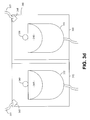
- Fig. 3d illustrates generally electrodes 332 and 333 pre-connected in a vertical orientation and enclosed in package 340.
- package 340 is a hard, tensile material.
- Package 340 includes two opposed interior surfaces 342 and 343. Electrode 332 is generally disposed upon interior surface 342 and electrode 333 is disposed upon interior surface 343. Prior to use, an adhesive layer 345 is located between interior surface 342 and electrode 332. Also, adhesive layer 346 is located between interior surface 343 and electrode 333.
- the embodiment shown in Fig. 3d shows electrodes 332 and 333 partially folded back for illustration purposes so that the components underneath the electrodes may be better understood.
- the embodiment illustrated in Fig. 3d further includes external electrical contacts 347 and 348 and interior electrical contacts 349 and 350.
- Internal electrical contacts 349 and 350 are disposed on interior surfaces 342 and 343 such that interior electrical contacts 349 and 350 provide an electrical connection with adhesive surfaces 345 and 346 when adhesive layers 345 and 346 are disposed upon interior surfaces 342 and 343.
- Interior electrical contacts 349 and 350 are in electrical contact with external electrical contacts 347 and 348.
- External electrical contacts are adapted to accept an electrical connection with electrical conductors 351 and 352 such that a closed loop connection is formed with a power source connected to electrical conductors 351 and 352 and a current can be forced through electrodes 332 and 333.
- electrode 332 and electrode 333 are removed from interior surfaces 342 and 343 and placed on a patient's chest so that interior electrical contacts 349 and 350 are no longer in electrical contact with adhesive layers 345 and 346 and electrical connection no longer exists between electrodes 332 and 333.
- Fig. 3e discloses an embodiment where electrodes 332 and 333 are disposed on interior surfaces 342 and 343.
- Surfaces 342 and 343 are comprised of a conductive surface such that current may travel between electrodes 332 and 333. Therefore, a connection is provided with the power source such that current can be forced through electrodes 332 and 333 via their electrical connection.
- the electrodes 322 and 333 are removed from surfaces 342 and 343 when used for defibrillation.
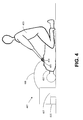
- Fig. 4 illustrates generally the use of electric defibrillator 401 to resuscitate patient 402.
- patient 402 is in need of therapy from electric defibrillator 401.
- Rescuer 403 places both electrodes 404 in contact with skin 405 of patient 402.
- Adhesive layers of electrodes are disposed upon skin such that adhesive layers provide an electrical connection with skin 405.
- Electrodes 404 are electrically connected to the remainder of defibrillator 401 through electrical conductors 408. According to the example of Fig.
- Fig. 5 illustrates generally one embodiment of electric defibrillator 501 according to the subject matter disclosed herein.
- the example of Fig. 5 is identical to the example shown in Fig. 1 , except defibrillation electrodes are pre-connected as shown in Fig. 3a, Fig. 3b , Fig. 3c , Fig. 3d , or Fig. 3e .
- the connection between the pre-connected electrodes provides a current path such that a current can be driven through the electrodes.
- the hydrogel layers 208 of each electrode are in electrical contact with each other. It is to be understood that any pre-connection current path that is provided between hydrogel layers 208 is within the scope of the subject matter disclosed herein.
- defibrillator 501 drives current through electrical conductors 506 and through hydrogel portions 208 of electrodes 505.
- controller 503 initiates, adjusts, and/or monitors the current driven through hydrogel portions 208 of electrodes 505.
- the current may be a DC current, an AC current, an intermittent DC current, or an intermittent AC current.
- current is driven at a rate and intensity such that hydrogel layers 208 of electrodes 505 absorb the current and thaw electrode 505 without overheating and therefore damaging any component of electrodes 505.
- Controller 503 initiates, adjusts, and/or monitors driving of current into electrodes 505.
- the embodiments disclosed in Fig. 5 allow the ability to automatically thaw electrodes 505 and can be implemented via a programming change of controller 503.
- Fig. 6a and Fig. 6b illustrate generally one embodiment of defibrillator 607 adapted to thaw electrode 601 according to the subject matter disclosed herein.
- foil 602 of electrode 601 is used as a heating element to defrost electrode 601.
- Fig. 6a illustrates electrode 601.
- Electrode 601 is similar to electrodes 201 illustrated in FIGS. 2a and 2b , however electrode 601 includes two leads 603 and 604.
- leads 603 and 604 are connected to electrical conductors 605 and 606 and provide an electrical connection between foil 602 and the other components located in the base 611 of the defibrillator including the power source.
- defibrillator 607 is adapted to direct current through foil 602. Because foil 602 is made of a conductive element, current directed through foil 602 causes heating of foil 602 and thus dissipates heat to thaw electrode 601.
- foil 602 is not a flat, uniform layer such as the conductive layer 206 or foil 209 illustrated in Fig. 2 .
- Fig. 6b illustrates an alternative embodiment of foil 602 as a serpentine structure.
- the arrangement of foil 602 as a serpentine structure as opposed to a flat, uniform layer maximizes the ability of foil 602 to dissipate heat.
- foil 602 is arranged as a helical structure to maximize the ability of foil 602 to dissipate heat. It is to be understood that any shape, size, or structure of foil 602 is within the scope of the subject matter described herein.
- Fig. 7 illustrates generally one embodiment of defibrillator 701 adapted to thaw electrodes 705 and 706 according to the subject matter disclosed herein.
- Pre-connected electrodes 705 and 706 are similar to pre-connected electrodes 322 and 323 as illustrated in Fig. 3c , and further include electrode separator 707 similar to electrode separator 320.
- the embodiment illustrated in Fig. 7 further includes resistive heating element 702.
- Resistive heating element 702 is embedded in electrode separator 707.
- Resistive heating element 702 is adapted to include leads 704 and 703.
- Leads 703 and 704 are further adapted to be connected to the base 711 and power source of the defibrillator via conductors 713 and 715 such that a current may be driven through resistive heating element 702.
- Resistive heating element 702 is adapted to emit heat and thus thaw electrodes 705 and 706. It is to be understood that resistive heating element 702 may be arranged in any structure to maximize the ability of resistive heating element 702 to dissipate heat to defrost the electrodes 705 and 706. In one example, resistive heating element 702 may be a serpentine structure as illustrated in Fig. 6b .
- Fig. 8 illustrates generally one embodiment of defibrillator adapted to thaw electrodes 832 and 833 according to the subject matter disclosed herein.
- Fig. 8 includes a package 840 having two interior surfaces 842 and 843. Electrodes 832 and 833 and respective adhesive layers 845 and 846 are located on these interior surfaces and are partially folded back for illustration purposes.
- Package 840 is similar to package 340 of FIG. 3d , however, package 840 includes conductive element 800.
- Package 840 includes external connectors 847 and 848.
- Conductive element 800 provides an electrical connection between external connectors 847 and 848. According to this embodiment, conductive element 800 functions as a heating element.
- External connectors 847 and 848 are adapted to be connected to a power source through electrical connectors 851 and 852 and conductive element 800 such that heat is emitted into package 840.
- Package 840 acts as an insulator trapping emitted heat, and thus frozen electrodes 832 and 833 are thawed. It is to be understood that package 840 is used for illustration purposes only. Any package for electrodes may include conductive element 800 and external connectors 847 and 848 for purposes of thawing a frozen electrode.
- conductive element 800 may be arranged in any structure to maximize the ability of conductive element to dissipate heat into package 840. In one example, conductive element 800 may be a serpentine structure as illustrated in Fig. 6b .
- Fig. 9 illustrates one embodiment of a method of defrosting an electrode of an electric defibrillator according to the subject matter disclosed herein.
- a rescuer has access to an electric defibrillator 101, as shown generally in Fig. 1 .
- Defibrillator 101 includes at least one frozen electrode 105. Electrode 105 may be frozen because, for example, it has been stored in an automobile in cold weather for a period of time.
- the power of defibrillator 101 is activated.
- controller 103 receives a signal initiated by rescuer that indicates electrode 105 is frozen.
- one or more pulses of electrical energy are delivered to electrode 105.
- the delivery of electrical energy is at a level sufficient to defrost the electrode 105.
- electrical energy is delivered such that damage to components of electrode 105 is minimized.
- Fig. 10 illustrates one embodiment of a method of defrosting an electrode of an electric defibrillator 101 according to the subject matter disclosed herein.
- a rescuer has access to an electric defibrillator 101.
- Defibrillator 101 includes at least one frozen electrode 105.
- Defibrillator 101 further includes at least one sensor 108 adapted to measure a temperature of electrode 105 and communicate that temperature to controller 103.
- the power of defibrillator 101 is activated.
- controller 103 receives a signal from sensor 108 that indicates a measurement of temperature.
- controller 103 is adapted to compare the temperature measurement to one or more thresholds.
- controller 103 may be adapted to vary the duration or intensity of an electrical impulse based on the measured temperature of electrode 105, or any other condition internal or external to defibrillator 101.
- One or more pulses of electrical energy are delivered to electrode 105.
- the delivery of electrical energy is at a level sufficient to defrost electrode 105.
- electrical energy is delivered such that damage to components of electrode 105 is minimized.
- Fig. 11 illustrates generally one example of a method of assisting a rescuer to defrost electrode 105 of defibrillator 101.
- electric defibrillator 101 is provided to a rescuer.
- Electrode 105 of defibrillator 101 is frozen.
- sensors 108 of defibrillator 101 may determine that electrode 105 is frozen.
- rescuer may determine that electrode 105 is frozen.
- the rescuer is provided instructions to defrost electrode 105.
- instructions may indicate to a rescuer how to initiate the defrosting of electrode 105.
- instructions may indicate that controller 103 has initiated defrosting electrode 105.
- controller 103 may initiate defrosting of electrode 105 automatically.
- an electrical impulse is provided sufficient to defrost electrode 105 as discussed herein with respect to FIGS. 3a-e , 5 , 6a-b , 7 , and 8 .
- electrical energy is delivered such that damage to components of electrode 105 is minimized.
- Fig. 12 illustrates generally an example of electric defibrillator 1201 according to the subject matter disclosed herein.
- Electric defibrillator 1201 includes electrode defroster 1210.
- electrode defroster 1210 is coupled to electric defibrillator 1201.
- electrode defroster 1210 is a component separate to defibrillator 1201.
- controller 1203 is adapted to initiate, adjust, and/or monitor electrode defroster 1210.
- Defibrillator 1201 also includes electrode 1205.
- electrode 1205 is stored in package 1211.
- electrode defroster 1210 is adapted to be positioned proximally to package 1211 to defrost electrode 1205.
- electrode defroster 1210 is adapted to be positioned proximally to electrode 1205 outside of package to defrost electrode 1205. In one embodiment, electrode defroster 1210 is adapted to contact electrode pouch 1211 to defrost electrode 1205. In one embodiment, electrode defroster 1210 is adapted to be positioned proximally to electrode 1205 outside of package to defrost electrode 1205. In various embodiments, electrode defroster 1210 is adapted to contact at least one portion of electrode 1205. In one embodiment, electrode defroster 1210 is adapted to contact lead 1204 of electrode 1205. In another embodiment, electrode defroster 1210 is adapted to contact conductive portion 1206 of electrode 1205. In yet another embodiment, electrode defroster is adapted to contact patient contact portion 1209 of electrode 1205.
- electrode defroster 1210 is adapted to deliver energy to electrode 1205. In various embodiments, electrode defroster 1210 is adapted to deliver energy in the form of electrical energy to electrode 1205. According to these embodiments, electrical energy is applied to one or more portions of electrode 1205 such that electrical energy is converted to heat. In one embodiment, electrical energy is applied to lead 1204 of electrode 1205. In another embodiment, electrical energy is applied to conductive layer 1206 of electrode 1205. In another embodiment, electrical energy is applied to hydrogel layer 1207 of electrode 1205. In another embodiment, electrical energy is applied to foil layer 1208. In various alternative embodiments, electrode defroster is adapted to deliver heat directly to electrode 1205. In one embodiment, electrode defroster is a heat element. In various embodiments, electrode defroster is placed proximally to any portion of electrode 1205 to defrost it.
- electrode defroster 1210 is powered by defibrillator 1201. In another embodiment, electrode defroster is powered by a power source external to defibrillator 1201.
- FIG. 13 illustrates generally a flow chart example of a method defrosting an electrode according to the subject matter disclosed herein.
- Fig. 13 illustrates one embodiment of a method of defrosting an electrode of an electric defibrillator 1201 according to the subject matter disclosed herein.
- a rescuer has access to an electric defibrillator 1201.
- Defibrillator 1201 includes at least one frozen electrode 1205.
- Defibrillator 1201 further includes at least one electrode defroster 1210.
- the power of defibrillator is active.
- a rescuer determines that electrode 1205 is frozen.
- rescuer determines how to dispose electrode defroster 1210 in relation to electrode 1205.
- rescuer disposes electrode defroster 1210 proximally to or in contact with electrode 1205.
- electrode defroster 1210 thaws electrode 1205.
- Fig. 14 illustrates generally a flow chart example of a method of assisting a rescuer to defrost electrode 1205.
- defibrillator 1205 is provided to a rescuer. Electrode 1205 of defibrillator 1201 is frozen.
- electrode defroster 1210 is provided to rescuer.
- instructions to use electrode defroster 1210 to defrost electrode 1205 are provided to rescuer.
- the rescuer positions electrode defroster 1210 as directed by instructions provided at 1403.
- electrode defroster 1210 delivers energy to defrost electrode 1205.
- Fig. 15 illustrates a similar embodiment of a method of controlling the operating conditions of defibrillation electrodes of an automated external defibrillator.
- a pair of preconnected electrodes is provided which are adapted to releasably attach to an external portion of a patient.
- the electrodes generally attachable to the chest of a patient needing resuscitation.
- Each of the electrodes provided has a conductive interface medium having physical properties dependent upon a desired temperature range of about 32OF to 122OF.
- the AED is automatically caused to deliver a limited electrical impulse to the defibrillation electrodes so as to heat the defibrillation electrodes to the desired temperature range.
- Using a sensor to indicate if the electrode is frozen may be included in this method. Further, such a process may utilize a resistive heating element or be done during operation of the AED prior to delivery of a defibrillator pulse through the electrodes.
- current shall be kept low enough to prevent damaging local heating effects.
- the pulse duration and periodicity of the current shall be compatible with the specific electrode type and characteristics to allow for an even and non-destructive energy absorption by the electrodes to effect an even and successful defrosting.
- a preferred pulse energy may be about 10 to 20 Joules, for example.
- the number of pulses may be determined by the initial temperature of the electrodes and the mass of the electrodes.
- the time between pulses may be determined by the ability of a specific electrode to absorb thermal energy.
- the voltage used shall be low enough to avoid internal arcing and to keep the current low enough to prevent excessive local heating. For example, a preferred embodiment could use a voltage range of 50 to 500 Volts.
- Total defrosting energy may be approximately in the 200J range in some embodiments which may be roughly equivalent to one low energy defibrillation shock.
- resistance is generally kept low enough not to interfere with the defibrillation function. This might be below 5 Ohms, in some embodiments, for example.
- a variety of safety features are possible to avoid danger associated with energy impulses used to defrost electrodes as set forth.
- the electrodes are contained in the packaging, there will be no hazard.
- Some devices may utilize features to detect if this packaging is torn.
- Safety can also be insured via voice and/or visual prompts similar to those used when energy is being delivered to the patient. When defrosting is in progress, the user will be instructed to not handle nor open the electrode pouch. When defrosting is complete, the normal prompting sequence can be resumed.
Abstract
Description
- The present invention relates to methods and devices for resuscitating a patient. More particularly, the present invention relates to electric defibrillators and thawing frozen defibrillation electrodes used with electric defibrillators.
- Many techniques exist for resuscitating a patient suffering from a life threatening condition. Patient conditions that may require resuscitation include, but are not limited to, cardiac arrest, bradycardia, tachycardia, ventricular fibrillation and respiratory arrest. One example of a technique for resuscitating a patient is to use an electric defibrillator to apply electrical energy to the patient.
- The human heart contracts when stimulated by an intrinsic electric impulse generated by the human body itself. When a patient undergoes some form of cardiac arrest, or where the heart has stopped beating or is beating at an unsafe rate, it is often valuable to apply an unnatural electrical impulse to restart or sync a human heart so that it can continue to function and thus keep a patient alive. Electrical impulse therapy is often administered using an electric defibrillator. An electric defibrillator typically includes a power source and at least two defibrillation electrodes that provide a connection with the skin of a patient for electricity to be administered to the patient. Typically, defibrillation electrodes are disposed upon the chest region of a patient such that electrical energy can be administered to the patient.
- Portable versions of electric defibrillators have existed since the 1960's. The use of these devices is now widespread. Both emergency and non-emergency personnel often have access to portable versions of electric defibrillators, known as automated external defibrillators (AEDs), in case of emergencies. Examples of such AEDs include: Cardiac Science's Powerheart®, Medtronic's LIFEPAK®, Defibtech's Lifeline™, Phillips' HeartStart™, and Zoll's AED Plus®.
- It is important that these AEDs be continuously operational and ready for use on a moment's notice. Any delay in the ability of a rescuer to use such a device in an emergency can mean the difference between life and death for a patient. One such delay may occur as a result of the defibrillation electrodes being frozen. Because AEDs are highly portable, they are often stored in automobiles or other unheated places. In cold weather, portions of the defibrillation electrodes may freeze. In order for a defibrillation electrode to properly deliver an appropriate electrical impulse as described, the electrode must not be frozen. In current practice, if an electrode is frozen, a rescuer must either replace the electrode with an unfrozen one, or use external means such as a heater to thaw the electrode. Often, in critical situations, a frozen electrode results in valuable time wasted and in the worst case may result in death to a patient.
- Accordingly, the present invention overcomes the problems of the prior art by providing a method and device to efficiently defrost defibrillation electrodes. In one embodiment, an automated external defibrillator with defrosting capabilities includes a portable housing containing a battery powered energy source and a controller. The embodiment also includes at least a pair of electrodes operably coupled to the housing. In this embodiment, the electrodes are releasably attachable to an external portion of a patient in need of resuscitation. Further, each of the electrodes includes a conductive interface medium having physical properties dependent upon a desired temperature range of about 32OF to 122OF. Also, the controller is configured to selectively heat the conductive interface medium by applying a limited amount of electrical impulse from the energy source to raise the temperature of the conductive interface medium toward the desired range.
- According to another embodiment of the present invention, an automated external defibrillator with defrosting capabilities includes a pair of preconnected electrodes including an outer hydrogel layer on each electrode having physical properties dependent upon a normal temperature range of about 32OF to 122OF. Also included is a housing having a battery powered energy source and a controller that selectively heats the hydrogel layer by applying a limited amount of electrical impulse to raise the temperature of the hydrogel layer to the normal range.
- In yet another embodiment according to the present invention, a method of controlling the operating conditions of defibrillation electrodes of an automated external defibrillator includes providing a pair of electrodes releasably attachable with an external portion of a patient in need of resuscitation where each electrode has a conductive interface medium having physical properties dependent upon a desired temperature range of about 32OF to 122OF. The method also including automatically causing the automated external defibrillator to deliver a limited electrical impulse to the defibrillation electrodes so as to heat the defibrillation electrodes to the desired temperature range.
- The invention may be more completely understood in consideration of the following detailed description of various embodiments of the invention in connection with the accompanying drawings, in which:
-
FIG. 1 illustrates generally an example of an electric defibrillator; -
FIG. 2a illustrates generally an example of a defibrillator electrode; -
FIG. 2b illustrates generally an alternate example of a defibrillator electrode; -
FIG. 3a illustrates generally an example of pre-connected electrodes; -
FIG. 3b illustrates generally an example of pre-connected electrodes; -
FIG. 3c illustrates generally an example of pre-connected electrodes; -
FIG. 3d illustrates generally an example of pre-connected electrodes; -
FIG. 3e illustrates generally an example of pre-connected electrodes; -
FIG. 4 illustrates generally a rescuer using an electric defibrillator on a patient; -
FIG. 5 illustrates generally an electric defibrillator according to the subject matter disclosed herein; -
FIG. 6a and FIG. 6b illustrate generally an electric defibrillator according to the subject matter disclosed herein; -
FIG. 7 illustrates generally an electric defibrillator according to the subject matter disclosed herein; -
FIG. 8 illustrates generally an electric defibrillator according to the subject matter disclosed herein; -
FIG. 9 illustrates generally a flow chart example of a method of defrosting an electrode according to the subject matter disclosed herein; -
FIG. 10 illustrates generally a flow chart example of a method of defrosting an electrode according to the subject matter disclosed herein; -
FIG. 11 illustrates generally a flow chart example of a method of assisting a rescuer to defrost an electrode according to the subject matter disclosed herein; -
FIG. 12 illustrates generally an electric defibrillator according to the subject matter disclosed herein; -
FIG. 13 illustrates generally a flow chart example of a method of assisting a rescuer to defrost an electrode according to the subject matter disclosed herein; -
FIG. 14 illustrates generally a flow chart example of a method of assisting a rescuer to defrost an electrode according to the subject matter disclosed herein; and -
FIG. 15 illustrates generally a flow chart example of a method of controlling the operating conditions of a defibrillation electrode according to the subject matter disclosed herein. - The invention may be embodied in other specific forms without departing from the essential attributes thereof; therefore, the illustrated embodiments should be considered in all respects as illustrative and not restrictive.
-
Fig. 1 illustrates generally an example of anelectric defibrillator 101. In various embodiments,electric defibrillator 101 includes one ormore power sources 102. In various embodiments,power source 102 includes one or more batteries. In various embodiments,power source 102 also includes one or more capacitors. In various embodiments,power source 102 is adapted to provide energy sufficient to provide an electrical impulse capable of stimulating a heart. In various embodiments,defibrillator 101 includescontroller 103.Controller 103 is adapted to initiate, adjust, and/or monitor functions ofdefibrillator 101. In various embodiments,controller 103 is adapted to initiate or adjust delivery of an electric impulse for purposes of providing electrical therapy to a patient. In some embodiments,defibrillator 101 further includesuser interface 107.User interface 107 is adapted to allow communication between a user andcontroller 103. In various embodiments,user interface 107 is adapted to allow a user toprogram controller 103. - In various embodiments,
defibrillator 101 also includes at least oneelectrode 105. In various embodiments,electrode 105 is connected toelectrical conductor 106 such thatelectrode 105 is in electrical connection withpower source 102. In various embodiments,electrode 105 is adapted to be placed in contact with a patient and serve as a connection for delivery of electrical energy to a patient. Typically, at least twoelectrodes 105 are required so that an electrical connection is provided across the body of a patient such that a current may be driven through the body of a patient to stimulate the patient's heart. - In various embodiments,
defibrillator 101 further includes at least onesensor 108. Thesesensors 108 are generally operably connected tocontroller 103.Sensor 108 may be adapted to determine conditions of components ofdefibrillator 101. In one embodiment,sensor 108 is adapted to determine a temperature ofelectrode 105. In one embodiment,sensor 108 is adapted to determine the amount of energy stored inpower source 102. In various embodiments,sensor 108 is adapted to determine conditions of components ofdefibrillator 101. In one embodiment,sensor 108 is adapted to determine whetherelectrode 105 is frozen. In various embodiments,sensor 108 is adapted to determine conditions external todefibrillator 101. In some embodiments,sensor 108 may also be capable of detecting defibrillator movement or other events commonly occurring prior to defibrillation, such as movement of a defibrillator panel. - Generally,
electrode 105 is a defibrillation electrode adapted to apply an electric impulse to a patient. Ifelectrode 105 is frozen, or very cold, it will likely not function properly to apply an electrical impulse to a patient. Therefore, afrozen electrode 105 must be defrosted quickly and efficiently so thatelectrode 105 will function effectively to apply an electrical impulse to a patient. More specifically, certain components of the electrode such as a hydrogel layer or other conductive interface medium can readily freeze when temperatures drop below a desired temperature range. The physical properties of the conductive interface medium often requires a desired, normal temperature range for operation to generally be about 32°F to 122°F. Such a range is needed for safe and reliable defibrillation operation. Consequently, the controller of the present invention is designed to selectively heat the conductive interface medium by applying a limited amount of electrical impulse from the energy source to raise the temperature of the conductive interface medium to the desired range. - In embodiments of the present invention, using the controller to selectively signal the electrical impulses or other means to warm and defrost the electrodes can be done in a variety of ways. As mentioned, a
sensor 108 in the defibrillator may detect a freezing temperature in the proximity of the electrodes. Alternatively, a sensor that detects when the defibrillator is moved or opened can signal defrosting, as such actions will often occur just prior to defibrillation. Sending sensor data to the controller in this way will also ensure the defibrillator is ready for use at desired times. Additional signalling events may follow routine or automatic self testing operations by the defibrillator. - The controller may be programmed with various safety features to recognize and prevent continuous or repetitive signalling data that might result in significant battery usage and drain. Such features ensure that the defibrillator will be sufficiently charged for proper use.
-
Fig. 2a illustrates generally one example of adefibrillation electrode 201.Defibrillation electrode 201 includes alead location 202 and apatient contact surface 203. In various embodiments,patient surface 203 is adapted to be placed in contact with a patient in order to deliver electrical therapy to the patient.Lead location 202 is adapted to connect anelectrode 201 to anelectrical conductor 106. In an embodiment,lead location 202 includes a lead 204 which may be made of a conductive material.Electrode 201 further includesbase layer 205. In various embodiments,base layer 205 is any non-conductive material. According to the embodiment illustrated inFIG. 2a , lead 204 extends out fromelectrode 201 in order to create an electrical connection withpower source 102.Electrode 201 further includesconductive layer 206. In various embodiments,layer 206 may be made of foil or other conductive material. In various embodiments,conductive layer 206 is disposed in contact withlead 204 to provide electrical connectivity betweenlead 204 andconductive layer 206. -
Electrode 201 further includespatient contact portion 207.Conductive layer 206 is adapted to transfer voltage or current fromlead 204 topatient contact portion 207. In some embodiments,patient contact portion 207 may be entirely comprised of a hydrogel layer orconductive interface medium 208 disposed in electrical contact withconductive layer 206. Theconductive interface medium 208 is generally comprised of a conductive gel or similar material. However, in some cases theconductive interface medium 208 may be comprised of a tape or an adhesive of various kinds. For example, use of a nanopillar tape comprised of sheets of elastic, sticky polymers of a multiplicity of nanopillars or related medical tapes might be used in some designs. In general,hydrogel layer 208 is adapted to reduce variations in conductance whenpatient contact surface 203 is placed in contact with a patient and electrical energy is applied toelectrode 201. Thehydrogel 208 may have both conductive properties for transmitting energy and adhesive properties for attaching to a patient's skin. Specifically, the hydrogel helps make the electrodes releasably attachable to an external portion of a patient in need of resuscitation. -
Patient contact portion 207 may alternatively be comprised of a number of layers as set forth inFIG. 2b . One layer being ahydrogel layer 208 disposed in electric contact withconductive layer 206.Patient contact portion 207 may further include afoil layer 209 in contact withhydrogel layer 208. In variousembodiments foil layer 209 is a thin layer of conductive material adapted to transfer energy throughhydrogel layer 208 to thepatient contact surface 203.Patient contact portion 207 may further include anadhesive layer 210.Adhesive layer 210 is adapted to securepatient contact surface 203 to the skin of a patient. In various embodiments,adhesive layer 210 is made of any material with adhesive properties that further allows conduction of electricity to the skin of a patient. - It is to be understood when reading this application that the term "frozen" as used herein includes any temperature driven malfunction of
defibrillation electrode 201. In one example,electrode 201 does not function correctly becausepatient contact portion 207 is frozen, and therefore cannot ensure desired delivery of electrical energy topatient contact portion 207. - In various embodiments,
electrode 201 is enclosed in apackage 211 prior to use.Package 211 is adapted to protect the electrode prior to use to revive a patient. In one embodiment, asingle electrode 201 is enclosed inpackage 211. In another embodiment, two ormore electrodes 201 are enclosed inpackage 211. In various embodiments,package 211 is made of a material capable of protectingelectrode 201 prior to use. In one embodiment,package 211 is a thin, flexible material. In another embodiment,package 211 is a tensile material. In various embodiments,package 211 may include additional features such as additional electrical connections. -
Fig. 3a and Fig. 3b illustrate generally examples ofpre-connected electrodes Electrodes electrodes Fig. 3a ,electrodes breakable electrode connector 304. In various embodiments,breakable electrode connector 304 is a conductive material such as a metal that is adapted to provide an electrical connection to allow current to flow betweenelectrodes breakable electrode connector 304 is adapted to establish an electrical connection betweenhydrogel layers 305 or foil 306 ofelectrodes Electrodes electrodes electrodes breakable electrode connector 304 is broken, and an electrical connection no longer exists betweenelectrodes Fig. 3a only shows breakableelectrical connector 304 connecting hydro-gel layers, it is to be understood thatelectrical connector 304 can be adapted to connect any or all layers ofelectrodes - According to the embodiment shown in
Fig. 3b ,electrodes perforated electrode connector 314. In various embodiments,perforated electrode connector 314 is an extension ofhydrogel layer 315 that is perforated such that a rescuer can easily separateelectrode 312 fromelectrode 313. In various embodiments,perforated electrode connector 314 is adapted to establish an electrical connection betweenhydrogel layers 315 ofelectrodes Electrodes electrodes perforated electrode connector 314 is separated, and an electrical connection no longer exists betweenelectrodes Fig. 3b only shows perforatedelectrical connector 314 connecting hydrogel layers, it is to be understood that perforatedelectrical connector 314 can be adapted to connect any or all layers ofelectrodes electrodes FIG. 6b to provide a resistive heating element. -
Fig. 3c illustrates generallyelectrodes Fig. 3c ,adhesive layers 324 ofelectrodes electrode separator 320. In various embodiments,electrode separator 320 is made of a non-conductive material, and contacts bothadhesive layers 324.Adhesive layers 324 typically comprising hydrogel or a similar substance.Holes 321 inelectrode separator 320 allow adhesive fromadhesive layers 324 to establish an electrical connection betweenelectrode 322 andelectrode 323. To revive a patient,electrode 322 andelectrode 323 are removed fromelectrode separator 320, and electrical connection no longer exists betweenelectrodes -
Fig. 3d illustrates generallyelectrodes package 340. According to the embodiment disclosed inFig. 3d ,package 340 is a hard, tensile material.Package 340 includes two opposedinterior surfaces Electrode 332 is generally disposed uponinterior surface 342 andelectrode 333 is disposed uponinterior surface 343. Prior to use, anadhesive layer 345 is located betweeninterior surface 342 andelectrode 332. Also,adhesive layer 346 is located betweeninterior surface 343 andelectrode 333. The embodiment shown inFig. 3d showselectrodes adhesive layers electrical contacts adhesive layers interior surfaces - The embodiment illustrated in
Fig. 3d further includes externalelectrical contacts electrical contacts electrical contacts interior surfaces electrical contacts adhesive surfaces adhesive layers interior surfaces electrical contacts electrical contacts electrical conductors electrical conductors electrodes electrode 332 andelectrode 333 are removed frominterior surfaces electrical contacts adhesive layers electrodes -
Fig. 3e discloses an embodiment whereelectrodes interior surfaces Surfaces electrodes electrodes electrodes surfaces -
Fig. 4 illustrates generally the use of electric defibrillator 401 to resuscitatepatient 402. In the example ofFig. 4 ,patient 402 is in need of therapy from electric defibrillator 401.Rescuer 403 places bothelectrodes 404 in contact withskin 405 ofpatient 402. Adhesive layers of electrodes are disposed upon skin such that adhesive layers provide an electrical connection withskin 405.Electrodes 404 are electrically connected to the remainder of defibrillator 401 throughelectrical conductors 408. According to the example ofFig. 4 , whenrescuer 403 has placedelectrodes 404 in contact withpatient 402,rescuer 403 activates electric defibrillator 401 and an electrical impulse is applied frompower source 407 through theelectrodes 404 topatient 402.Controller 410 controls delivery of the electrical impulse. -
Fig. 5 illustrates generally one embodiment ofelectric defibrillator 501 according to the subject matter disclosed herein. The example ofFig. 5 is identical to the example shown inFig. 1 , except defibrillation electrodes are pre-connected as shown inFig. 3a, Fig. 3b ,Fig. 3c ,Fig. 3d , orFig. 3e . According to the embodiment shown inFigure 5 , the connection between the pre-connected electrodes provides a current path such that a current can be driven through the electrodes. Specifically, the hydrogel layers 208 of each electrode are in electrical contact with each other. It is to be understood that any pre-connection current path that is provided between hydrogel layers 208 is within the scope of the subject matter disclosed herein. - In various embodiments,
defibrillator 501 drives current throughelectrical conductors 506 and throughhydrogel portions 208 ofelectrodes 505. In various embodiments,controller 503 initiates, adjusts, and/or monitors the current driven throughhydrogel portions 208 ofelectrodes 505. In various embodiments, the current may be a DC current, an AC current, an intermittent DC current, or an intermittent AC current. In various embodiments, current is driven at a rate and intensity such that hydrogel layers 208 ofelectrodes 505 absorb the current andthaw electrode 505 without overheating and therefore damaging any component ofelectrodes 505.Controller 503 initiates, adjusts, and/or monitors driving of current intoelectrodes 505. The embodiments disclosed inFig. 5 allow the ability to automatically thawelectrodes 505 and can be implemented via a programming change ofcontroller 503. - In many cases, existing defibrillation circuits and controllers which utilize pre-connected electrodes may be used to deliver these energy bursts of electrical current directly into the electrodes. In such cases, it may be possible to achieve defrosting in even existing defibrillators by simply a programming change to the existing controller. Use of a software upgrade is particularly advantageous due to the low cost of implementation resulting from the continued use of an existing energy source and controller. Additionally, software upgrades lend themselves to an inherent ease of in-field implementation. The use of software upgrades may apply to various portable defibrillators with automated temperature sensing features as well.
-
Fig. 6a and Fig. 6b illustrate generally one embodiment ofdefibrillator 607 adapted to thawelectrode 601 according to the subject matter disclosed herein. According to this embodiment, foil 602 ofelectrode 601 is used as a heating element to defrostelectrode 601.Fig. 6a illustrateselectrode 601.Electrode 601 is similar toelectrodes 201 illustrated inFIGS. 2a and2b , however electrode 601 includes twoleads electrical conductors foil 602 and the other components located in thebase 611 of the defibrillator including the power source. To heat the electrode,defibrillator 607 is adapted to direct current throughfoil 602. Becausefoil 602 is made of a conductive element, current directed throughfoil 602 causes heating offoil 602 and thus dissipates heat to thawelectrode 601. - In various embodiments,
foil 602 is not a flat, uniform layer such as theconductive layer 206 or foil 209 illustrated inFig. 2 .Fig. 6b illustrates an alternative embodiment offoil 602 as a serpentine structure. The arrangement offoil 602 as a serpentine structure as opposed to a flat, uniform layer maximizes the ability offoil 602 to dissipate heat. In an alternative embodiment,foil 602 is arranged as a helical structure to maximize the ability offoil 602 to dissipate heat. It is to be understood that any shape, size, or structure offoil 602 is within the scope of the subject matter described herein. -
Fig. 7 illustrates generally one embodiment ofdefibrillator 701 adapted to thawelectrodes Pre-connected electrodes pre-connected electrodes Fig. 3c , and further includeelectrode separator 707 similar toelectrode separator 320. However, the embodiment illustrated inFig. 7 further includesresistive heating element 702.Resistive heating element 702 is embedded inelectrode separator 707.Resistive heating element 702 is adapted to includeleads Leads base 711 and power source of the defibrillator via conductors 713 and 715 such that a current may be driven throughresistive heating element 702.Resistive heating element 702 is adapted to emit heat and thus thawelectrodes resistive heating element 702 may be arranged in any structure to maximize the ability ofresistive heating element 702 to dissipate heat to defrost theelectrodes resistive heating element 702 may be a serpentine structure as illustrated inFig. 6b . -
Fig. 8 illustrates generally one embodiment of defibrillator adapted to thawelectrodes Fig. 8 includes apackage 840 having twointerior surfaces Electrodes adhesive layers Package 840 is similar to package 340 ofFIG. 3d , however,package 840 includesconductive element 800.Package 840 includesexternal connectors Conductive element 800 provides an electrical connection betweenexternal connectors conductive element 800 functions as a heating element.External connectors electrical connectors conductive element 800 such that heat is emitted intopackage 840. Package 840 acts as an insulator trapping emitted heat, and thusfrozen electrodes package 840 is used for illustration purposes only. Any package for electrodes may includeconductive element 800 andexternal connectors conductive element 800 may be arranged in any structure to maximize the ability of conductive element to dissipate heat intopackage 840. In one example,conductive element 800 may be a serpentine structure as illustrated inFig. 6b . -
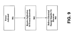
Fig. 9 illustrates one embodiment of a method of defrosting an electrode of an electric defibrillator according to the subject matter disclosed herein. According to the example ofFig. 9 , a rescuer has access to anelectric defibrillator 101, as shown generally inFig. 1 .Defibrillator 101 includes at least onefrozen electrode 105.Electrode 105 may be frozen because, for example, it has been stored in an automobile in cold weather for a period of time. At 901, the power ofdefibrillator 101 is activated. At 902,controller 103 receives a signal initiated by rescuer that indicateselectrode 105 is frozen. At 903, one or more pulses of electrical energy are delivered toelectrode 105. In various embodiments, the delivery of electrical energy is at a level sufficient to defrost theelectrode 105. In various embodiments, electrical energy is delivered such that damage to components ofelectrode 105 is minimized. -
Fig. 10 illustrates one embodiment of a method of defrosting an electrode of anelectric defibrillator 101 according to the subject matter disclosed herein. According to the example ofFig. 10 a rescuer has access to anelectric defibrillator 101.Defibrillator 101 includes at least onefrozen electrode 105.Defibrillator 101 further includes at least onesensor 108 adapted to measure a temperature ofelectrode 105 and communicate that temperature tocontroller 103. At 1001, the power ofdefibrillator 101 is activated. At 1002,controller 103 receives a signal fromsensor 108 that indicates a measurement of temperature. At 1003,controller 103 is adapted to compare the temperature measurement to one or more thresholds. At 1004, if the measured temperature is below a particular threshold, controller initiates the delivery of one or more electrical impulses as discussed herein with respect toFIGS. 3a-e ,5 , and6 . In various embodiments,controller 103 may be adapted to vary the duration or intensity of an electrical impulse based on the measured temperature ofelectrode 105, or any other condition internal or external todefibrillator 101. One or more pulses of electrical energy are delivered toelectrode 105. In various embodiments, the delivery of electrical energy is at a level sufficient to defrostelectrode 105. In various embodiments, electrical energy is delivered such that damage to components ofelectrode 105 is minimized. -
Fig. 11 illustrates generally one example of a method of assisting a rescuer to defrostelectrode 105 ofdefibrillator 101. At 1101,electric defibrillator 101 is provided to a rescuer.Electrode 105 ofdefibrillator 101 is frozen. In one embodiment,sensors 108 ofdefibrillator 101 may determine thatelectrode 105 is frozen. In another embodiment, rescuer may determine thatelectrode 105 is frozen. At 1102, the rescuer is provided instructions to defrostelectrode 105. In one embodiment, instructions may indicate to a rescuer how to initiate the defrosting ofelectrode 105. In other embodiments, instructions may indicate thatcontroller 103 has initiateddefrosting electrode 105. In yet other embodiments,controller 103 may initiate defrosting ofelectrode 105 automatically. At 1103, an electrical impulse is provided sufficient to defrostelectrode 105 as discussed herein with respect toFIGS. 3a-e ,5 ,6a-b ,7 , and8 . In various embodiments, electrical energy is delivered such that damage to components ofelectrode 105 is minimized. -
Fig. 12 illustrates generally an example ofelectric defibrillator 1201 according to the subject matter disclosed herein.Electric defibrillator 1201 includeselectrode defroster 1210. In one embodiment,electrode defroster 1210 is coupled toelectric defibrillator 1201. In another embodiment,electrode defroster 1210 is a component separate todefibrillator 1201. In an embodiment,controller 1203 is adapted to initiate, adjust, and/or monitorelectrode defroster 1210.Defibrillator 1201 also includeselectrode 1205. In various embodiments,electrode 1205 is stored inpackage 1211. In one embodiment,electrode defroster 1210 is adapted to be positioned proximally to package 1211 to defrostelectrode 1205. In one embodiment,electrode defroster 1210 is adapted to be positioned proximally toelectrode 1205 outside of package to defrostelectrode 1205. In one embodiment,electrode defroster 1210 is adapted to contactelectrode pouch 1211 to defrostelectrode 1205. In one embodiment,electrode defroster 1210 is adapted to be positioned proximally toelectrode 1205 outside of package to defrostelectrode 1205. In various embodiments,electrode defroster 1210 is adapted to contact at least one portion ofelectrode 1205. In one embodiment,electrode defroster 1210 is adapted to contactlead 1204 ofelectrode 1205. In another embodiment,electrode defroster 1210 is adapted to contactconductive portion 1206 ofelectrode 1205. In yet another embodiment, electrode defroster is adapted to contactpatient contact portion 1209 ofelectrode 1205. - In various embodiments,
electrode defroster 1210 is adapted to deliver energy toelectrode 1205. In various embodiments,electrode defroster 1210 is adapted to deliver energy in the form of electrical energy toelectrode 1205. According to these embodiments, electrical energy is applied to one or more portions ofelectrode 1205 such that electrical energy is converted to heat. In one embodiment, electrical energy is applied to lead 1204 ofelectrode 1205. In another embodiment, electrical energy is applied toconductive layer 1206 ofelectrode 1205. In another embodiment, electrical energy is applied tohydrogel layer 1207 ofelectrode 1205. In another embodiment, electrical energy is applied to foillayer 1208. In various alternative embodiments, electrode defroster is adapted to deliver heat directly toelectrode 1205. In one embodiment, electrode defroster is a heat element. In various embodiments, electrode defroster is placed proximally to any portion ofelectrode 1205 to defrost it. - In one embodiment,
electrode defroster 1210 is powered bydefibrillator 1201. In another embodiment, electrode defroster is powered by a power source external todefibrillator 1201.FIG. 13 illustrates generally a flow chart example of a method defrosting an electrode according to the subject matter disclosed herein.Fig. 13 illustrates one embodiment of a method of defrosting an electrode of anelectric defibrillator 1201 according to the subject matter disclosed herein. According to the example ofFig. 13 , a rescuer has access to anelectric defibrillator 1201.Defibrillator 1201 includes at least onefrozen electrode 1205.Defibrillator 1201 further includes at least oneelectrode defroster 1210. At 1301, the power of defibrillator is active. At 1302, a rescuer determines thatelectrode 1205 is frozen. At 1303, rescuer determines how to disposeelectrode defroster 1210 in relation toelectrode 1205. At 1304, rescuer disposeselectrode defroster 1210 proximally to or in contact withelectrode 1205. At 1305,electrode defroster 1210 thawselectrode 1205. -
Fig. 14 illustrates generally a flow chart example of a method of assisting a rescuer to defrostelectrode 1205. At 1401,defibrillator 1205 is provided to a rescuer.Electrode 1205 ofdefibrillator 1201 is frozen. At 1402,electrode defroster 1210 is provided to rescuer. At 1403, instructions to useelectrode defroster 1210 to defrostelectrode 1205 are provided to rescuer. At 1404 the rescuer positionselectrode defroster 1210 as directed by instructions provided at 1403. At 1404electrode defroster 1210 delivers energy to defrostelectrode 1205. -
Fig. 15 illustrates a similar embodiment of a method of controlling the operating conditions of defibrillation electrodes of an automated external defibrillator. First, at 1501 a pair of preconnected electrodes is provided which are adapted to releasably attach to an external portion of a patient. The electrodes generally attachable to the chest of a patient needing resuscitation. Each of the electrodes provided has a conductive interface medium having physical properties dependent upon a desired temperature range of about 32OF to 122OF. At 1502, the AED is automatically caused to deliver a limited electrical impulse to the defibrillation electrodes so as to heat the defibrillation electrodes to the desired temperature range. Using a sensor to indicate if the electrode is frozen may be included in this method. Further, such a process may utilize a resistive heating element or be done during operation of the AED prior to delivery of a defibrillator pulse through the electrodes. - In each of the methods and apparatus for defrosting defibrillation electrodes discussed in this application, current shall be kept low enough to prevent damaging local heating effects. Such parameters depend on the construction of the individual specific electrode. The pulse duration and periodicity of the current shall be compatible with the specific electrode type and characteristics to allow for an even and non-destructive energy absorption by the electrodes to effect an even and successful defrosting. A preferred pulse energy may be about 10 to 20 Joules, for example. In some embodiments, the number of pulses may be determined by the initial temperature of the electrodes and the mass of the electrodes. Also, in some embodiments, the time between pulses may be determined by the ability of a specific electrode to absorb thermal energy. Generally, the voltage used shall be low enough to avoid internal arcing and to keep the current low enough to prevent excessive local heating. For example, a preferred embodiment could use a voltage range of 50 to 500 Volts.
- Battery life of a defibrillator is generally only minimally affected by the use of the heating element as in most embodiments, the defrost is only utilized when needed and as needed. Total defrosting energy may be approximately in the 200J range in some embodiments which may be roughly equivalent to one low energy defibrillation shock. Also, when using the foil layer as a resistive element, resistance is generally kept low enough not to interfere with the defibrillation function. This might be below 5 Ohms, in some embodiments, for example.
- A variety of safety features are possible to avoid danger associated with energy impulses used to defrost electrodes as set forth. Typically, when the electrodes are contained in the packaging, there will be no hazard. Some devices may utilize features to detect if this packaging is torn. Safety can also be insured via voice and/or visual prompts similar to those used when energy is being delivered to the patient. When defrosting is in progress, the user will be instructed to not handle nor open the electrode pouch. When defrosting is complete, the normal prompting sequence can be resumed.
- Safety will also be ensured as current will be limited by controlling the voltage on the caps since the impedance range for the electrode is predictable within a sufficient degree of certainty.
- The embodiments above are intended to be illustrative and not limiting. Additional embodiments are within the claims. Although the present invention has been described with reference to particular embodiments, workers skilled in the art will recognize that changes may be made in form and detail without departing from the spirit and scope of the invention.
- Additional disclosure material that exemplifies at least a portion of the other features and functionality of the range of embodiments within the spirit and scope of the present invention can be found in U.S. Patent Nos.: 5,697,955, 5,817,151, 5,402,884, 5,579,919, 5,850,920, 5,984,102, 6,148,233 5,645,571, 5,792,190, 5,797,969, 5,919,212, 5,700,281, 6,029,085, 5,897,576, 6,173,203, 6,246,907, 6,263,238, 6,289,243, 7,006,865, 7,020,520, 6,658,290, 6,993,386, 6,321,113, 6,668,192, 7,065,401 5,955,956, and 5,897,576 the disclosures of which are hereby incorporated by reference in their entireties.
- Various modifications to the invention may be apparent to one of skill in the art upon reading this disclosure. For example, persons of ordinary skill in the relevant art will recognize that the various features described for the different embodiments of the invention can be suitably combined, un-combined, and re-combined with other features, alone, or in different combinations, within the spirit of the invention. Likewise, the various features described above should all be regarded as example embodiments, rather than limitations to the scope or spirit of the invention. Therefore, the above is not contemplated to limit the scope of the present invention.
- For purposes of interpreting the claims for the present invention, it is expressly intended that the provisions of Section 112, sixth paragraph of 35 U.S.C. are not to be invoked unless the specific terms "means for" or "step for" are recited in a claim.
Claims (19)
- An automated external defibrillator with defrosting capabilities comprising:a portable housing containing a battery powered energy source and a controller; andat least a pair of electrodes operably coupled to the housing, the electrodes being releasably attachable to an external portion of a patient in need of resuscitation, each of the electrodes including a conductive interface medium having physical properties dependent upon a desired temperature range of about 32°F to 122°F;wherein the controller is configured to selectively heat the conductive interface medium by applying a limited amount of electrical impulse from the energy source to raise the temperature of the conductive interface medium toward the desired range.
- The defibrillator of claim 1, wherein the conductive interface medium is hydrogel.
- The defibrillator of claim 1, wherein the conductive interface medium is an adhesive composition.
- The defibrillator of claim 1, wherein the conductive interface medium is a nanopillar tape.
- The defibrillator of claim 1, or of any preceding claim, further comprising a temperature sensor operably connected to the controller, wherein the controller heats the conductive interface medium in response to data from the temperature sensor.
- The defibrillator of claim 1, or of any preceding claim, further comprising a motion sensor operably coupled to the controller wherein the controller heats the conductive interface medium in response to a signal from the motion sensor indicative of movement or opening of the defibrillator.
- The defibrillator of claim 1, or of any preceding claim, wherein the electrodes further include a resistive element that is heated by impulses from the energy source to heat the conductive interface medium.
- The defibrillator of claim 7, wherein the resistive element has a serpentine configuration.
- The defibrillator of claim 7, or claim 8, wherein the resistive element is located between a pair of preconnected electrodes.
- The defibrillator of claim 7, or claim 8, or claim 9, further including an electrode package adapted to contain the resistive element and house the electrodes.
- An automated external defibrillator with defrosting capabilities comprising:a pair of preconnected electrodes including an outer hydrogel layer on each electrode having physical properties dependent upon a normal temperature range of about 32°F to 122°F; anda housing including a battery powered energy source and a controller that selectively heats the hydrogel layer by applying a limited amount of electrical impulse to raise the temperature of the hydrogel layer to the normal range.
- The defibrillator of claim 11, wherein the controller applies the limited electrical impulses in response to temperature sensor outputs.
- The defibrillator of claim 11, or claim 12, wherein the controller applies the limited electrical impulses in response to defibrillator movement.
- The defibrillator of claim 11, or claim 12, or claim 13, further including a package in which the preconnected electrodes are stored in a package containing a heating element.
- The defibrillator of claim 11, or of any of claims 12 to 14, further including a resistive heating element.
- A method of controlling the operating conditions of defibrillation electrodes of an automated external defibrillator, comprising:providing a pair of electrodes releasably attachable with an external portion of a patient in need of resuscitation, each electrode having a conductive interface medium having physical properties dependent upon a desired temperature range of about 32OF to 122OF; andautomatically causing the automated external defibrillator to deliver a limited electrical impulse to the defibrillation electrodes so as to heat the defibrillation electrodes to the desired temperature range.
- The method of claim 16, further including the step of providing a sensor to indicate when the defibrillation electrode is frozen and performing the step of automatically causing the automated external defibrillator to deliver a limited electrical impulse to the defibrillation electrodes in response to the sensor.
- The method of claim 16, or of claim 17, wherein the step of automatically causing the automated external defibrillator to deliver a limited electrical impulse to the defibrillation electrodes causes the limited electrical impulse to be conducted through a resistive heating element to thaw the electrode.
- The method of claim 16, or of claim 17, or of claim 18, wherein the steps are done during operation of the automated external defibrillator prior to delivery of a defibrillation pulse through the defibrillation electrodes.
Applications Claiming Priority (1)
| Application Number | Priority Date | Filing Date | Title |
|---|---|---|---|
| US12/055,817 US7881785B2 (en) | 2008-03-26 | 2008-03-26 | Method and apparatus for defrosting a defibrillation electrode |
Publications (3)
| Publication Number | Publication Date |
|---|---|
| EP2105162A2 true EP2105162A2 (en) | 2009-09-30 |
| EP2105162A3 EP2105162A3 (en) | 2013-02-06 |
| EP2105162B1 EP2105162B1 (en) | 2014-09-03 |
Family
ID=40942496
Family Applications (1)
| Application Number | Title | Priority Date | Filing Date |
|---|---|---|---|
| EP09156315.5A Not-in-force EP2105162B1 (en) | 2008-03-26 | 2009-03-26 | Method and apparatus for defrosting a defibrillation electrode |
Country Status (2)
| Country | Link |
|---|---|
| US (2) | US7881785B2 (en) |
| EP (1) | EP2105162B1 (en) |
Cited By (1)
| Publication number | Priority date | Publication date | Assignee | Title |
|---|---|---|---|---|
| WO2016092800A1 (en) * | 2014-12-09 | 2016-06-16 | Nihon Kohden Corporation | Defibrillation pad |
Families Citing this family (56)
| Publication number | Priority date | Publication date | Assignee | Title |
|---|---|---|---|---|
| US7881785B2 (en) * | 2008-03-26 | 2011-02-01 | Cardiac Science Corporation | Method and apparatus for defrosting a defibrillation electrode |
| US8239012B2 (en) | 2010-10-08 | 2012-08-07 | Cardiac Science Corporation | Microcontrolled electrocardiographic monitoring circuit with differential voltage encoding |
| US20120089000A1 (en) | 2010-10-08 | 2012-04-12 | Jon Mikalson Bishay | Ambulatory Electrocardiographic Monitor For Providing Ease Of Use In Women And Method Of Use |
| US8613708B2 (en) | 2010-10-08 | 2013-12-24 | Cardiac Science Corporation | Ambulatory electrocardiographic monitor with jumpered sensing electrode |
| US9037477B2 (en) | 2010-10-08 | 2015-05-19 | Cardiac Science Corporation | Computer-implemented system and method for evaluating ambulatory electrocardiographic monitoring of cardiac rhythm disorders |
| US9237858B2 (en) | 2011-02-09 | 2016-01-19 | West Affum Holdings Corp. | Detecting loss of full skin contact in patient electrodes |
| US10799137B2 (en) | 2013-09-25 | 2020-10-13 | Bardy Diagnostics, Inc. | System and method for facilitating a cardiac rhythm disorder diagnosis with the aid of a digital computer |
| US20190167139A1 (en) | 2017-12-05 | 2019-06-06 | Gust H. Bardy | Subcutaneous P-Wave Centric Insertable Cardiac Monitor For Long Term Electrocardiographic Monitoring |
| US9775536B2 (en) | 2013-09-25 | 2017-10-03 | Bardy Diagnostics, Inc. | Method for constructing a stress-pliant physiological electrode assembly |
| US9408551B2 (en) | 2013-11-14 | 2016-08-09 | Bardy Diagnostics, Inc. | System and method for facilitating diagnosis of cardiac rhythm disorders with the aid of a digital computer |
| US9433367B2 (en) | 2013-09-25 | 2016-09-06 | Bardy Diagnostics, Inc. | Remote interfacing of extended wear electrocardiography and physiological sensor monitor |
| US10165946B2 (en) | 2013-09-25 | 2019-01-01 | Bardy Diagnostics, Inc. | Computer-implemented system and method for providing a personal mobile device-triggered medical intervention |
| US10736529B2 (en) | 2013-09-25 | 2020-08-11 | Bardy Diagnostics, Inc. | Subcutaneous insertable electrocardiography monitor |
| US10736531B2 (en) | 2013-09-25 | 2020-08-11 | Bardy Diagnostics, Inc. | Subcutaneous insertable cardiac monitor optimized for long term, low amplitude electrocardiographic data collection |
| US10624551B2 (en) | 2013-09-25 | 2020-04-21 | Bardy Diagnostics, Inc. | Insertable cardiac monitor for use in performing long term electrocardiographic monitoring |
| US10888239B2 (en) | 2013-09-25 | 2021-01-12 | Bardy Diagnostics, Inc. | Remote interfacing electrocardiography patch |
| US10433751B2 (en) | 2013-09-25 | 2019-10-08 | Bardy Diagnostics, Inc. | System and method for facilitating a cardiac rhythm disorder diagnosis based on subcutaneous cardiac monitoring data |
| US10667711B1 (en) | 2013-09-25 | 2020-06-02 | Bardy Diagnostics, Inc. | Contact-activated extended wear electrocardiography and physiological sensor monitor recorder |
| US9345414B1 (en) | 2013-09-25 | 2016-05-24 | Bardy Diagnostics, Inc. | Method for providing dynamic gain over electrocardiographic data with the aid of a digital computer |
| US9615763B2 (en) | 2013-09-25 | 2017-04-11 | Bardy Diagnostics, Inc. | Ambulatory electrocardiography monitor recorder optimized for capturing low amplitude cardiac action potential propagation |
| US10806360B2 (en) | 2013-09-25 | 2020-10-20 | Bardy Diagnostics, Inc. | Extended wear ambulatory electrocardiography and physiological sensor monitor |
| US9433380B1 (en) | 2013-09-25 | 2016-09-06 | Bardy Diagnostics, Inc. | Extended wear electrocardiography patch |
| US9730593B2 (en) | 2013-09-25 | 2017-08-15 | Bardy Diagnostics, Inc. | Extended wear ambulatory electrocardiography and physiological sensor monitor |
| US9619660B1 (en) | 2013-09-25 | 2017-04-11 | Bardy Diagnostics, Inc. | Computer-implemented system for secure physiological data collection and processing |
| US9655537B2 (en) | 2013-09-25 | 2017-05-23 | Bardy Diagnostics, Inc. | Wearable electrocardiography and physiology monitoring ensemble |
| US9504423B1 (en) | 2015-10-05 | 2016-11-29 | Bardy Diagnostics, Inc. | Method for addressing medical conditions through a wearable health monitor with the aid of a digital computer |
| US9700227B2 (en) | 2013-09-25 | 2017-07-11 | Bardy Diagnostics, Inc. | Ambulatory electrocardiography monitoring patch optimized for capturing low amplitude cardiac action potential propagation |
| US9655538B2 (en) | 2013-09-25 | 2017-05-23 | Bardy Diagnostics, Inc. | Self-authenticating electrocardiography monitoring circuit |
| US9364155B2 (en) | 2013-09-25 | 2016-06-14 | Bardy Diagnostics, Inc. | Self-contained personal air flow sensing monitor |
| US9717432B2 (en) | 2013-09-25 | 2017-08-01 | Bardy Diagnostics, Inc. | Extended wear electrocardiography patch using interlaced wire electrodes |
| US9408545B2 (en) | 2013-09-25 | 2016-08-09 | Bardy Diagnostics, Inc. | Method for efficiently encoding and compressing ECG data optimized for use in an ambulatory ECG monitor |
| US10820801B2 (en) | 2013-09-25 | 2020-11-03 | Bardy Diagnostics, Inc. | Electrocardiography monitor configured for self-optimizing ECG data compression |
| US10463269B2 (en) | 2013-09-25 | 2019-11-05 | Bardy Diagnostics, Inc. | System and method for machine-learning-based atrial fibrillation detection |
| WO2015048194A1 (en) | 2013-09-25 | 2015-04-02 | Bardy Diagnostics, Inc. | Self-contained personal air flow sensing monitor |
| US11723575B2 (en) | 2013-09-25 | 2023-08-15 | Bardy Diagnostics, Inc. | Electrocardiography patch |
| US10251576B2 (en) | 2013-09-25 | 2019-04-09 | Bardy Diagnostics, Inc. | System and method for ECG data classification for use in facilitating diagnosis of cardiac rhythm disorders with the aid of a digital computer |
| US11213237B2 (en) | 2013-09-25 | 2022-01-04 | Bardy Diagnostics, Inc. | System and method for secure cloud-based physiological data processing and delivery |
| US9737224B2 (en) | 2013-09-25 | 2017-08-22 | Bardy Diagnostics, Inc. | Event alerting through actigraphy embedded within electrocardiographic data |
| US9717433B2 (en) | 2013-09-25 | 2017-08-01 | Bardy Diagnostics, Inc. | Ambulatory electrocardiography monitoring patch optimized for capturing low amplitude cardiac action potential propagation |
| US10433748B2 (en) | 2013-09-25 | 2019-10-08 | Bardy Diagnostics, Inc. | Extended wear electrocardiography and physiological sensor monitor |
| USD744659S1 (en) | 2013-11-07 | 2015-12-01 | Bardy Diagnostics, Inc. | Extended wear electrode patch |
| USD801528S1 (en) | 2013-11-07 | 2017-10-31 | Bardy Diagnostics, Inc. | Electrocardiography monitor |
| USD717955S1 (en) | 2013-11-07 | 2014-11-18 | Bardy Diagnostics, Inc. | Electrocardiography monitor |
| USD793566S1 (en) | 2015-09-10 | 2017-08-01 | Bardy Diagnostics, Inc. | Extended wear electrode patch |
| USD831833S1 (en) | 2013-11-07 | 2018-10-23 | Bardy Diagnostics, Inc. | Extended wear electrode patch |
| USD892340S1 (en) | 2013-11-07 | 2020-08-04 | Bardy Diagnostics, Inc. | Extended wear electrode patch |
| USD766447S1 (en) | 2015-09-10 | 2016-09-13 | Bardy Diagnostics, Inc. | Extended wear electrode patch |
| US11155428B2 (en) | 2018-02-23 | 2021-10-26 | International Test Solutions, Llc | Material and hardware to automatically clean flexible electronic web rolls |
| US11756811B2 (en) | 2019-07-02 | 2023-09-12 | International Test Solutions, Llc | Pick and place machine cleaning system and method |
| US11696681B2 (en) | 2019-07-03 | 2023-07-11 | Bardy Diagnostics Inc. | Configurable hardware platform for physiological monitoring of a living body |
| US11096579B2 (en) | 2019-07-03 | 2021-08-24 | Bardy Diagnostics, Inc. | System and method for remote ECG data streaming in real-time |
| US11116451B2 (en) | 2019-07-03 | 2021-09-14 | Bardy Diagnostics, Inc. | Subcutaneous P-wave centric insertable cardiac monitor with energy harvesting capabilities |
| US11211242B2 (en) | 2019-11-14 | 2021-12-28 | International Test Solutions, Llc | System and method for cleaning contact elements and support hardware using functionalized surface microfeatures |
| US11318550B2 (en) | 2019-11-14 | 2022-05-03 | International Test Solutions, Llc | System and method for cleaning wire bonding machines using functionalized surface microfeatures |
| US11035898B1 (en) * | 2020-05-11 | 2021-06-15 | International Test Solutions, Inc. | Device and method for thermal stabilization of probe elements using a heat conducting wafer |
| JP2023548776A (en) * | 2020-10-14 | 2023-11-21 | ハートヒーロー, インコーポレイテッド | Automated external defibrillator system and instructions for use |
Citations (21)
| Publication number | Priority date | Publication date | Assignee | Title |
|---|---|---|---|---|
| US5402884A (en) | 1992-09-24 | 1995-04-04 | Surviva Link Corporation | Medical electrode packaging technology |
| US5645571A (en) | 1995-08-01 | 1997-07-08 | Survivalink Corporation | Automated external defibrillator with lid activated self-test system |
| US5697955A (en) | 1996-05-10 | 1997-12-16 | Survivalink Corporation | Defibrillator electrodes and date code detector circuit |
| US5700281A (en) | 1996-06-04 | 1997-12-23 | Survivalink Corporation | Stage and state monitoring automated external defibrillator |
| US5797969A (en) | 1995-08-01 | 1998-08-25 | Survivalink Corporation | One button lid activated automatic external defibrillator |
| US5817151A (en) | 1996-06-04 | 1998-10-06 | Survivalink Corporation | Circuit detectable packaged medical electrodes |
| US5897576A (en) | 1997-04-08 | 1999-04-27 | Survivalink Corporation | Automated external defibrillator with the ability to sense temperature |
| US5955956A (en) | 1997-04-08 | 1999-09-21 | Survivalink Corporation | Audible alarm system for an automated external defibrillator |
| US5984102A (en) | 1992-09-24 | 1999-11-16 | Survivalink Corporation | Medical electrode packaging technology |
| US6029085A (en) | 1997-04-09 | 2000-02-22 | Survivalink Corporation | Charging and safety control for automated external defibrillator and method |
| US6148233A (en) | 1997-03-07 | 2000-11-14 | Cardiac Science, Inc. | Defibrillation system having segmented electrodes |
| US6173203B1 (en) | 1997-04-08 | 2001-01-09 | Survivalink Corpration | Circuit mounting system for automated external defibrillator circuits |
| US6246907B1 (en) | 1999-12-01 | 2001-06-12 | Cardiacscience, Inc. | Automatic external cardioverter/defibrillator with cardiac rate detector and method of operating the same |
| US6263238B1 (en) | 1998-04-16 | 2001-07-17 | Survivalink Corporation | Automatic external defibrillator having a ventricular fibrillation detector |
| US6289243B1 (en) | 1999-12-01 | 2001-09-11 | Cardiac Science, Inc. | Automatic external cardioverter/defibrillator with tachyarrhythmia detector using a modulation (amplitude and frequency) domain function |
| US6321113B1 (en) | 1998-03-31 | 2001-11-20 | Survivalink Corporation | Automatic external defibrillator first responder and clinical data outcome management system |
| US6658290B1 (en) | 2000-06-12 | 2003-12-02 | Cardiac Science, Inc. | Public access defibrillator |
| US6668192B1 (en) | 1997-04-08 | 2003-12-23 | Cardiac Science, Inc. | Automated external defibrilator with the ability to store rescue information |
| US7006865B1 (en) | 2000-03-09 | 2006-02-28 | Cardiac Science Inc. | Automatic defibrillator module for integration with standard patient monitoring equipment |
| US7020520B2 (en) | 2003-04-23 | 2006-03-28 | Cardiac Science, Inc. | Defibrillator enclosure system |
| US7065401B2 (en) | 2002-05-08 | 2006-06-20 | Michael Worden | Method of applying electrical signals to a patient and automatic wearable external defibrillator |
Family Cites Families (17)
| Publication number | Priority date | Publication date | Assignee | Title |
|---|---|---|---|---|
| US597969A (en) * | 1898-01-25 | Safety-fuse | ||
| US7132161B2 (en) | 1999-06-14 | 2006-11-07 | Energy Science Laboratories, Inc. | Fiber adhesive material |
| US6603318B2 (en) * | 2001-02-22 | 2003-08-05 | Koninklijke Philips Electronics N.V. | Method of determining when electrode pads are unsuitable for use by detecting relative humidity |
| US6799063B2 (en) * | 2002-02-27 | 2004-09-28 | Medivance Incorporated | Temperature control pads with integral electrodes |
| US7452452B2 (en) | 2002-04-29 | 2008-11-18 | The Trustees Of Boston College | Carbon nanotube nanoelectrode arrays |
| US6842328B2 (en) | 2003-05-30 | 2005-01-11 | Joachim Hossick Schott | Capacitor and method for producing a capacitor |
| US7481952B2 (en) | 2004-04-29 | 2009-01-27 | Compagnie Plastic Omnium | Electrically conductive PTFE tape |
| US7526345B2 (en) | 2004-06-10 | 2009-04-28 | Medtronic Emergency Response Systems, Inc. | Assessing medical electrode condition |
| TWI463615B (en) | 2004-11-04 | 2014-12-01 | Taiwan Semiconductor Mfg Co Ltd | Nanotube-based directionally-conductive adhesive |
| WO2007124477A2 (en) | 2006-04-21 | 2007-11-01 | William Marsh Rice University | Embedded arrays of vertically aligned carbon nanotube carpets and methods for making them |
| FR2903622B1 (en) * | 2006-07-17 | 2008-10-03 | Sidel Participations | DEVICE FOR DEPOSITING A COATING ON AN INTERNAL SIDE OF A CONTAINER |
| WO2008091386A2 (en) | 2006-08-04 | 2008-07-31 | Northwestern University | Biomimetic modular adhesive complex: material, methods and applications therefore |
| CN101280161B (en) | 2007-04-06 | 2013-01-09 | 清华大学 | Conducting adhesive tape and manufacturing method thereof |
| US8974904B2 (en) | 2007-07-05 | 2015-03-10 | University Of Dayton | Aligned carbon nanotubes for dry adhesives and methods for producing same |
| WO2009016546A2 (en) | 2007-07-30 | 2009-02-05 | Philips Intellectual Property & Standards Gmbh | Nanostructures and method for making them |
| US20090238815A1 (en) | 2008-03-18 | 2009-09-24 | Medtronic Vascular, Inc. | Nondegradable Hydrogels For Medical Device Application |
| US7881785B2 (en) | 2008-03-26 | 2011-02-01 | Cardiac Science Corporation | Method and apparatus for defrosting a defibrillation electrode |
-
2008
- 2008-03-26 US US12/055,817 patent/US7881785B2/en not_active Expired - Fee Related
-
2009
- 2009-03-26 EP EP09156315.5A patent/EP2105162B1/en not_active Not-in-force
-
2011
- 2011-01-07 US US12/986,672 patent/US8260414B2/en not_active Expired - Fee Related
Patent Citations (27)
| Publication number | Priority date | Publication date | Assignee | Title |
|---|---|---|---|---|
| US5579919A (en) | 1992-09-24 | 1996-12-03 | Survivalink Corporation | Medical electrode packaging technology |
| US5984102A (en) | 1992-09-24 | 1999-11-16 | Survivalink Corporation | Medical electrode packaging technology |
| US5402884A (en) | 1992-09-24 | 1995-04-04 | Surviva Link Corporation | Medical electrode packaging technology |
| US5850920A (en) | 1992-09-24 | 1998-12-22 | Survivalink Corporation | Medical electrode packaging technology |
| US5645571A (en) | 1995-08-01 | 1997-07-08 | Survivalink Corporation | Automated external defibrillator with lid activated self-test system |
| US5792190A (en) | 1995-08-01 | 1998-08-11 | Survivalink Corporation | Automated external defibrillator operator interface |
| US5797969A (en) | 1995-08-01 | 1998-08-25 | Survivalink Corporation | One button lid activated automatic external defibrillator |
| US5645571B1 (en) | 1995-08-01 | 1999-08-24 | Surviva Link Corp | Automated external defibrillator with lid activated self-test system |
| US5919212A (en) | 1995-08-08 | 1999-07-06 | Survivalink Corporation | Watchdog timer for automated external defibrillator |
| US5697955A (en) | 1996-05-10 | 1997-12-16 | Survivalink Corporation | Defibrillator electrodes and date code detector circuit |
| US5817151A (en) | 1996-06-04 | 1998-10-06 | Survivalink Corporation | Circuit detectable packaged medical electrodes |
| US5700281A (en) | 1996-06-04 | 1997-12-23 | Survivalink Corporation | Stage and state monitoring automated external defibrillator |
| US6148233A (en) | 1997-03-07 | 2000-11-14 | Cardiac Science, Inc. | Defibrillation system having segmented electrodes |
| US5955956A (en) | 1997-04-08 | 1999-09-21 | Survivalink Corporation | Audible alarm system for an automated external defibrillator |
| US5897576A (en) | 1997-04-08 | 1999-04-27 | Survivalink Corporation | Automated external defibrillator with the ability to sense temperature |
| US6173203B1 (en) | 1997-04-08 | 2001-01-09 | Survivalink Corpration | Circuit mounting system for automated external defibrillator circuits |
| US6668192B1 (en) | 1997-04-08 | 2003-12-23 | Cardiac Science, Inc. | Automated external defibrilator with the ability to store rescue information |
| US6029085A (en) | 1997-04-09 | 2000-02-22 | Survivalink Corporation | Charging and safety control for automated external defibrillator and method |
| US6321113B1 (en) | 1998-03-31 | 2001-11-20 | Survivalink Corporation | Automatic external defibrillator first responder and clinical data outcome management system |
| US6263238B1 (en) | 1998-04-16 | 2001-07-17 | Survivalink Corporation | Automatic external defibrillator having a ventricular fibrillation detector |
| US6246907B1 (en) | 1999-12-01 | 2001-06-12 | Cardiacscience, Inc. | Automatic external cardioverter/defibrillator with cardiac rate detector and method of operating the same |
| US6289243B1 (en) | 1999-12-01 | 2001-09-11 | Cardiac Science, Inc. | Automatic external cardioverter/defibrillator with tachyarrhythmia detector using a modulation (amplitude and frequency) domain function |
| US7006865B1 (en) | 2000-03-09 | 2006-02-28 | Cardiac Science Inc. | Automatic defibrillator module for integration with standard patient monitoring equipment |
| US6658290B1 (en) | 2000-06-12 | 2003-12-02 | Cardiac Science, Inc. | Public access defibrillator |
| US6993386B2 (en) | 2000-06-12 | 2006-01-31 | Cardiac Science Inc. | Public access defibrillator |
| US7065401B2 (en) | 2002-05-08 | 2006-06-20 | Michael Worden | Method of applying electrical signals to a patient and automatic wearable external defibrillator |
| US7020520B2 (en) | 2003-04-23 | 2006-03-28 | Cardiac Science, Inc. | Defibrillator enclosure system |
Cited By (3)
| Publication number | Priority date | Publication date | Assignee | Title |
|---|---|---|---|---|
| WO2016092800A1 (en) * | 2014-12-09 | 2016-06-16 | Nihon Kohden Corporation | Defibrillation pad |
| JP2016106914A (en) * | 2014-12-09 | 2016-06-20 | 日本光電工業株式会社 | Defibrillation pad |
| US10232166B2 (en) | 2014-12-09 | 2019-03-19 | Nihon Kohden Corporation | Defibrillation pad |
Also Published As
| Publication number | Publication date |
|---|---|
| US20110106192A1 (en) | 2011-05-05 |
| US7881785B2 (en) | 2011-02-01 |
| EP2105162B1 (en) | 2014-09-03 |
| US8260414B2 (en) | 2012-09-04 |
| US20090248128A1 (en) | 2009-10-01 |
| EP2105162A3 (en) | 2013-02-06 |
Similar Documents
| Publication | Publication Date | Title |
|---|---|---|
| EP2105162B1 (en) | Method and apparatus for defrosting a defibrillation electrode | |
| US7526345B2 (en) | Assessing medical electrode condition | |
| EP2978488B1 (en) | Detecting cutaneous electrode peeling using electrode-skin impedance | |
| US11253714B2 (en) | Impedance spectroscopy for defibrillator applications | |
| US6148233A (en) | Defibrillation system having segmented electrodes | |
| US6178357B1 (en) | Electrode pad system and defibrillator electrode pad that reduces the risk of peripheral shock | |
| US6859664B2 (en) | Cardiac rhythm management system with defibrillation threshold prediction | |
| US20100076368A1 (en) | Electrotransport Delivery Device Having Improved Safety and Reduced Abuse Potential | |
| US9138573B2 (en) | External defibrillators,transcutaneous electrodes for same, and methods of use | |
| US8036742B2 (en) | Apparatus and methods for fibrillation and defibrillation | |
| JP4245923B2 (en) | 4-contact identification defibrillator electrode system | |
| WO2005092434A1 (en) | Defibrillation electrode having drug delivery capability | |
| WO1998039061A9 (en) | Wearable defibrillation system | |
| JP2005522284A (en) | Defibrillation system and method designed for quick installation | |
| WO2000074769A9 (en) | Cardiac shock electrode system and corresponding implantable defibrillator system | |
| US8972005B2 (en) | Subthreshold lead impedance measurement for subcutaneous device | |
| CA2459049A1 (en) | Automated external defibrillator (aed) system | |
| Altamura et al. | Transthoracic DC shock may represent a serious hazard in pacemaker dependent patients | |
| JP2010509006A (en) | Disposable external defibrillator | |
| WO2007134288A2 (en) | Electrode-battery assembly for tens device | |
| EP2691146B1 (en) | Defibrillator electrode pad with two peel tabs | |
| EP2366426B1 (en) | Electrode delivery system | |
| AU2002324850A1 (en) | Automated external defibrillator (AED) system | |
| BR102016007241A2 (en) | A method for establishing an electrostimulation protocol for the control of pelvic pain and the use of a portable electrostimulation device for the control of pelvic pain using the above-mentioned protocol. |
Legal Events
| Date | Code | Title | Description |
|---|---|---|---|
| PUAI | Public reference made under article 153(3) epc to a published international application that has entered the european phase |
Free format text: ORIGINAL CODE: 0009012 |
|
| AK | Designated contracting states |
Kind code of ref document: A2 Designated state(s): AT BE BG CH CY CZ DE DK EE ES FI FR GB GR HR HU IE IS IT LI LT LU LV MC MK MT NL NO PL PT RO SE SI SK TR |
|
| AX | Request for extension of the european patent |
Extension state: AL BA RS |
|
| PUAL | Search report despatched |
Free format text: ORIGINAL CODE: 0009013 |
|
| AK | Designated contracting states |
Kind code of ref document: A3 Designated state(s): AT BE BG CH CY CZ DE DK EE ES FI FR GB GR HR HU IE IS IT LI LT LU LV MC MK MT NL NO PL PT RO SE SI SK TR |
|
| AX | Request for extension of the european patent |
Extension state: AL BA RS |
|
| RIC1 | Information provided on ipc code assigned before grant |
Ipc: A61N 1/39 20060101AFI20130102BHEP |
|
| 17P | Request for examination filed |
Effective date: 20130805 |
|
| RBV | Designated contracting states (corrected) |
Designated state(s): AT BE BG CH CY CZ DE DK EE ES FI FR GB GR HR HU IE IS IT LI LT LU LV MC MK MT NL NO PL PT RO SE SI SK TR |
|
| AKX | Designation fees paid |
Designated state(s): AT BE BG CH CY LI |
|
| REG | Reference to a national code |
Ref country code: DE Ref legal event code: R108 |
|
| RBV | Designated contracting states (corrected) |
Designated state(s): AT BE BG CH CY CZ LI |
|
| RBV | Designated contracting states (corrected) |
Designated state(s): AT BE BG CH CY CZ DE DK EE ES FI FR GB GR HR HU IE IS IT LI LT LU LV MC MK MT NL NO PL PT RO SE SI SK TR |
|
| REG | Reference to a national code |
Ref country code: DE Ref legal event code: R108 Effective date: 20131009 |
|
| GRAP | Despatch of communication of intention to grant a patent |
Free format text: ORIGINAL CODE: EPIDOSNIGR1 |
|
| INTG | Intention to grant announced |
Effective date: 20140205 |
|
| RAP1 | Party data changed (applicant data changed or rights of an application transferred) |
Owner name: CARDIAC SCIENCE CORPORATION |
|
| RIN1 | Information on inventor provided before grant (corrected) |
Inventor name: NASSIF, RABIH D. Inventor name: PETERSON, PETER M. |
|
| GRAP | Despatch of communication of intention to grant a patent |
Free format text: ORIGINAL CODE: EPIDOSNIGR1 |
|
| GRAS | Grant fee paid |
Free format text: ORIGINAL CODE: EPIDOSNIGR3 |
|
| INTG | Intention to grant announced |
Effective date: 20140701 |
|
| GRAA | (expected) grant |
Free format text: ORIGINAL CODE: 0009210 |
|
| AK | Designated contracting states |
Kind code of ref document: B1 Designated state(s): AT BE BG CH CY CZ DE DK EE ES FI FR GB GR HR HU IE IS IT LI LT LU LV MC MK MT NL NO PL PT RO SE SI SK TR |
|
| REG | Reference to a national code |
Ref country code: GB Ref legal event code: FG4D |
|
| REG | Reference to a national code |
Ref country code: AT Ref legal event code: REF Ref document number: 685237 Country of ref document: AT Kind code of ref document: T Effective date: 20140915 Ref country code: CH Ref legal event code: EP |
|
| REG | Reference to a national code |
Ref country code: IE Ref legal event code: FG4D |
|
| REG | Reference to a national code |
Ref country code: DE Ref legal event code: R096 Ref document number: 602009026384 Country of ref document: DE Effective date: 20141016 |
|
| REG | Reference to a national code |
Ref country code: AT Ref legal event code: MK05 Ref document number: 685237 Country of ref document: AT Kind code of ref document: T Effective date: 20140903 |
|
| PG25 | Lapsed in a contracting state [announced via postgrant information from national office to epo] |
Ref country code: GR Free format text: LAPSE BECAUSE OF FAILURE TO SUBMIT A TRANSLATION OF THE DESCRIPTION OR TO PAY THE FEE WITHIN THE PRESCRIBED TIME-LIMIT Effective date: 20141204 Ref country code: NO Free format text: LAPSE BECAUSE OF FAILURE TO SUBMIT A TRANSLATION OF THE DESCRIPTION OR TO PAY THE FEE WITHIN THE PRESCRIBED TIME-LIMIT Effective date: 20141203 Ref country code: SE Free format text: LAPSE BECAUSE OF FAILURE TO SUBMIT A TRANSLATION OF THE DESCRIPTION OR TO PAY THE FEE WITHIN THE PRESCRIBED TIME-LIMIT Effective date: 20140903 Ref country code: FI Free format text: LAPSE BECAUSE OF FAILURE TO SUBMIT A TRANSLATION OF THE DESCRIPTION OR TO PAY THE FEE WITHIN THE PRESCRIBED TIME-LIMIT Effective date: 20140903 Ref country code: ES Free format text: LAPSE BECAUSE OF FAILURE TO SUBMIT A TRANSLATION OF THE DESCRIPTION OR TO PAY THE FEE WITHIN THE PRESCRIBED TIME-LIMIT Effective date: 20140903 Ref country code: LT Free format text: LAPSE BECAUSE OF FAILURE TO SUBMIT A TRANSLATION OF THE DESCRIPTION OR TO PAY THE FEE WITHIN THE PRESCRIBED TIME-LIMIT Effective date: 20140903 |
|
| REG | Reference to a national code |
Ref country code: NL Ref legal event code: VDEP Effective date: 20140903 |
|
| REG | Reference to a national code |
Ref country code: LT Ref legal event code: MG4D |
|
| PG25 | Lapsed in a contracting state [announced via postgrant information from national office to epo] |
Ref country code: AT Free format text: LAPSE BECAUSE OF FAILURE TO SUBMIT A TRANSLATION OF THE DESCRIPTION OR TO PAY THE FEE WITHIN THE PRESCRIBED TIME-LIMIT Effective date: 20140903 Ref country code: LV Free format text: LAPSE BECAUSE OF FAILURE TO SUBMIT A TRANSLATION OF THE DESCRIPTION OR TO PAY THE FEE WITHIN THE PRESCRIBED TIME-LIMIT Effective date: 20140903 Ref country code: CY Free format text: LAPSE BECAUSE OF FAILURE TO SUBMIT A TRANSLATION OF THE DESCRIPTION OR TO PAY THE FEE WITHIN THE PRESCRIBED TIME-LIMIT Effective date: 20140903 Ref country code: HR Free format text: LAPSE BECAUSE OF FAILURE TO SUBMIT A TRANSLATION OF THE DESCRIPTION OR TO PAY THE FEE WITHIN THE PRESCRIBED TIME-LIMIT Effective date: 20140903 |
|
| PG25 | Lapsed in a contracting state [announced via postgrant information from national office to epo] |
Ref country code: NL Free format text: LAPSE BECAUSE OF FAILURE TO SUBMIT A TRANSLATION OF THE DESCRIPTION OR TO PAY THE FEE WITHIN THE PRESCRIBED TIME-LIMIT Effective date: 20140903 |
|
| PG25 | Lapsed in a contracting state [announced via postgrant information from national office to epo] |
Ref country code: PT Free format text: LAPSE BECAUSE OF FAILURE TO SUBMIT A TRANSLATION OF THE DESCRIPTION OR TO PAY THE FEE WITHIN THE PRESCRIBED TIME-LIMIT Effective date: 20150105 Ref country code: RO Free format text: LAPSE BECAUSE OF FAILURE TO SUBMIT A TRANSLATION OF THE DESCRIPTION OR TO PAY THE FEE WITHIN THE PRESCRIBED TIME-LIMIT Effective date: 20140903 Ref country code: SK Free format text: LAPSE BECAUSE OF FAILURE TO SUBMIT A TRANSLATION OF THE DESCRIPTION OR TO PAY THE FEE WITHIN THE PRESCRIBED TIME-LIMIT Effective date: 20140903 Ref country code: CZ Free format text: LAPSE BECAUSE OF FAILURE TO SUBMIT A TRANSLATION OF THE DESCRIPTION OR TO PAY THE FEE WITHIN THE PRESCRIBED TIME-LIMIT Effective date: 20140903 Ref country code: EE Free format text: LAPSE BECAUSE OF FAILURE TO SUBMIT A TRANSLATION OF THE DESCRIPTION OR TO PAY THE FEE WITHIN THE PRESCRIBED TIME-LIMIT Effective date: 20140903 Ref country code: IS Free format text: LAPSE BECAUSE OF FAILURE TO SUBMIT A TRANSLATION OF THE DESCRIPTION OR TO PAY THE FEE WITHIN THE PRESCRIBED TIME-LIMIT Effective date: 20150103 |
|
| PG25 | Lapsed in a contracting state [announced via postgrant information from national office to epo] |
Ref country code: PL Free format text: LAPSE BECAUSE OF FAILURE TO SUBMIT A TRANSLATION OF THE DESCRIPTION OR TO PAY THE FEE WITHIN THE PRESCRIBED TIME-LIMIT Effective date: 20140903 |
|
| REG | Reference to a national code |
Ref country code: DE Ref legal event code: R097 Ref document number: 602009026384 Country of ref document: DE |
|
| PLBE | No opposition filed within time limit |
Free format text: ORIGINAL CODE: 0009261 |
|
| STAA | Information on the status of an ep patent application or granted ep patent |
Free format text: STATUS: NO OPPOSITION FILED WITHIN TIME LIMIT |
|
| PG25 | Lapsed in a contracting state [announced via postgrant information from national office to epo] |
Ref country code: DK Free format text: LAPSE BECAUSE OF FAILURE TO SUBMIT A TRANSLATION OF THE DESCRIPTION OR TO PAY THE FEE WITHIN THE PRESCRIBED TIME-LIMIT Effective date: 20140903 |
|
| 26N | No opposition filed |
Effective date: 20150604 |
|
| PG25 | Lapsed in a contracting state [announced via postgrant information from national office to epo] |
Ref country code: IT Free format text: LAPSE BECAUSE OF FAILURE TO SUBMIT A TRANSLATION OF THE DESCRIPTION OR TO PAY THE FEE WITHIN THE PRESCRIBED TIME-LIMIT Effective date: 20140903 |
|
| PG25 | Lapsed in a contracting state [announced via postgrant information from national office to epo] |
Ref country code: MC Free format text: LAPSE BECAUSE OF FAILURE TO SUBMIT A TRANSLATION OF THE DESCRIPTION OR TO PAY THE FEE WITHIN THE PRESCRIBED TIME-LIMIT Effective date: 20140903 Ref country code: LU Free format text: LAPSE BECAUSE OF FAILURE TO SUBMIT A TRANSLATION OF THE DESCRIPTION OR TO PAY THE FEE WITHIN THE PRESCRIBED TIME-LIMIT Effective date: 20150326 |
|
| REG | Reference to a national code |
Ref country code: CH Ref legal event code: PL |
|
| PG25 | Lapsed in a contracting state [announced via postgrant information from national office to epo] |
Ref country code: SI Free format text: LAPSE BECAUSE OF FAILURE TO SUBMIT A TRANSLATION OF THE DESCRIPTION OR TO PAY THE FEE WITHIN THE PRESCRIBED TIME-LIMIT Effective date: 20140903 |
|
| REG | Reference to a national code |
Ref country code: IE Ref legal event code: MM4A |
|
| PG25 | Lapsed in a contracting state [announced via postgrant information from national office to epo] |
Ref country code: CH Free format text: LAPSE BECAUSE OF NON-PAYMENT OF DUE FEES Effective date: 20150331 Ref country code: IE Free format text: LAPSE BECAUSE OF NON-PAYMENT OF DUE FEES Effective date: 20150326 Ref country code: LI Free format text: LAPSE BECAUSE OF NON-PAYMENT OF DUE FEES Effective date: 20150331 |
|
| REG | Reference to a national code |
Ref country code: FR Ref legal event code: PLFP Year of fee payment: 8 |
|
| PG25 | Lapsed in a contracting state [announced via postgrant information from national office to epo] |
Ref country code: BE Free format text: LAPSE BECAUSE OF FAILURE TO SUBMIT A TRANSLATION OF THE DESCRIPTION OR TO PAY THE FEE WITHIN THE PRESCRIBED TIME-LIMIT Effective date: 20140903 |
|
| PG25 | Lapsed in a contracting state [announced via postgrant information from national office to epo] |
Ref country code: MT Free format text: LAPSE BECAUSE OF FAILURE TO SUBMIT A TRANSLATION OF THE DESCRIPTION OR TO PAY THE FEE WITHIN THE PRESCRIBED TIME-LIMIT Effective date: 20140903 |
|
| REG | Reference to a national code |
Ref country code: FR Ref legal event code: PLFP Year of fee payment: 9 |
|
| PG25 | Lapsed in a contracting state [announced via postgrant information from national office to epo] |
Ref country code: BG Free format text: LAPSE BECAUSE OF FAILURE TO SUBMIT A TRANSLATION OF THE DESCRIPTION OR TO PAY THE FEE WITHIN THE PRESCRIBED TIME-LIMIT Effective date: 20140903 Ref country code: HU Free format text: LAPSE BECAUSE OF FAILURE TO SUBMIT A TRANSLATION OF THE DESCRIPTION OR TO PAY THE FEE WITHIN THE PRESCRIBED TIME-LIMIT; INVALID AB INITIO Effective date: 20090326 |
|
| PG25 | Lapsed in a contracting state [announced via postgrant information from national office to epo] |
Ref country code: TR Free format text: LAPSE BECAUSE OF FAILURE TO SUBMIT A TRANSLATION OF THE DESCRIPTION OR TO PAY THE FEE WITHIN THE PRESCRIBED TIME-LIMIT Effective date: 20140903 |
|
| REG | Reference to a national code |
Ref country code: FR Ref legal event code: PLFP Year of fee payment: 10 |
|
| PGFP | Annual fee paid to national office [announced via postgrant information from national office to epo] |
Ref country code: DE Payment date: 20180322 Year of fee payment: 10 Ref country code: GB Payment date: 20180321 Year of fee payment: 10 |
|
| PGFP | Annual fee paid to national office [announced via postgrant information from national office to epo] |
Ref country code: FR Payment date: 20180330 Year of fee payment: 10 |
|
| PG25 | Lapsed in a contracting state [announced via postgrant information from national office to epo] |
Ref country code: MK Free format text: LAPSE BECAUSE OF FAILURE TO SUBMIT A TRANSLATION OF THE DESCRIPTION OR TO PAY THE FEE WITHIN THE PRESCRIBED TIME-LIMIT Effective date: 20140903 |
|
| REG | Reference to a national code |
Ref country code: DE Ref legal event code: R119 Ref document number: 602009026384 Country of ref document: DE |
|
| GBPC | Gb: european patent ceased through non-payment of renewal fee |
Effective date: 20190326 |
|
| PG25 | Lapsed in a contracting state [announced via postgrant information from national office to epo] |
Ref country code: DE Free format text: LAPSE BECAUSE OF NON-PAYMENT OF DUE FEES Effective date: 20191001 Ref country code: GB Free format text: LAPSE BECAUSE OF NON-PAYMENT OF DUE FEES Effective date: 20190326 |
|
| PG25 | Lapsed in a contracting state [announced via postgrant information from national office to epo] |
Ref country code: FR Free format text: LAPSE BECAUSE OF NON-PAYMENT OF DUE FEES Effective date: 20190331 |