EP2105336A2 - Driving force transmission device for four-wheel-drive vehicle - Google Patents
Driving force transmission device for four-wheel-drive vehicle Download PDFInfo
- Publication number
- EP2105336A2 EP2105336A2 EP09154612A EP09154612A EP2105336A2 EP 2105336 A2 EP2105336 A2 EP 2105336A2 EP 09154612 A EP09154612 A EP 09154612A EP 09154612 A EP09154612 A EP 09154612A EP 2105336 A2 EP2105336 A2 EP 2105336A2
- Authority
- EP
- European Patent Office
- Prior art keywords
- driving force
- wheel
- clutch
- force transmission
- cam
- Prior art date
- Legal status (The legal status is an assumption and is not a legal conclusion. Google has not performed a legal analysis and makes no representation as to the accuracy of the status listed.)
- Granted
Links
- 230000005540 biological transmission Effects 0.000 title claims abstract description 63
- 230000007246 mechanism Effects 0.000 claims abstract description 194
- 239000003921 oil Substances 0.000 claims description 90
- 125000006850 spacer group Chemical group 0.000 claims description 34
- 239000010687 lubricating oil Substances 0.000 claims description 21
- 230000008859 change Effects 0.000 claims description 12
- 238000006073 displacement reaction Methods 0.000 claims description 11
- 238000005299 abrasion Methods 0.000 claims description 7
- 238000006243 chemical reaction Methods 0.000 claims description 2
- 238000010586 diagram Methods 0.000 description 22
- 230000007423 decrease Effects 0.000 description 11
- 230000003247 decreasing effect Effects 0.000 description 6
- 238000000034 method Methods 0.000 description 6
- 230000000717 retained effect Effects 0.000 description 6
- 210000000078 claw Anatomy 0.000 description 4
- 238000005461 lubrication Methods 0.000 description 3
- 239000000463 material Substances 0.000 description 3
- 238000003825 pressing Methods 0.000 description 3
- 230000004044 response Effects 0.000 description 3
- 230000008901 benefit Effects 0.000 description 2
- 230000001276 controlling effect Effects 0.000 description 2
- 238000001816 cooling Methods 0.000 description 2
- 230000009467 reduction Effects 0.000 description 2
- 230000009471 action Effects 0.000 description 1
- 238000001514 detection method Methods 0.000 description 1
- 230000004048 modification Effects 0.000 description 1
- 238000012986 modification Methods 0.000 description 1
- 230000002265 prevention Effects 0.000 description 1
- 230000001105 regulatory effect Effects 0.000 description 1
- 238000003756 stirring Methods 0.000 description 1
Images


Classifications
-
- B—PERFORMING OPERATIONS; TRANSPORTING
- B60—VEHICLES IN GENERAL
- B60K—ARRANGEMENT OR MOUNTING OF PROPULSION UNITS OR OF TRANSMISSIONS IN VEHICLES; ARRANGEMENT OR MOUNTING OF PLURAL DIVERSE PRIME-MOVERS IN VEHICLES; AUXILIARY DRIVES FOR VEHICLES; INSTRUMENTATION OR DASHBOARDS FOR VEHICLES; ARRANGEMENTS IN CONNECTION WITH COOLING, AIR INTAKE, GAS EXHAUST OR FUEL SUPPLY OF PROPULSION UNITS IN VEHICLES
- B60K23/00—Arrangement or mounting of control devices for vehicle transmissions, or parts thereof, not otherwise provided for
- B60K23/08—Arrangement or mounting of control devices for vehicle transmissions, or parts thereof, not otherwise provided for for changing number of driven wheels, for switching from driving one axle to driving two or more axles
- B60K23/0808—Arrangement or mounting of control devices for vehicle transmissions, or parts thereof, not otherwise provided for for changing number of driven wheels, for switching from driving one axle to driving two or more axles for varying torque distribution between driven axles, e.g. by transfer clutch
-
- F—MECHANICAL ENGINEERING; LIGHTING; HEATING; WEAPONS; BLASTING
- F16—ENGINEERING ELEMENTS AND UNITS; GENERAL MEASURES FOR PRODUCING AND MAINTAINING EFFECTIVE FUNCTIONING OF MACHINES OR INSTALLATIONS; THERMAL INSULATION IN GENERAL
- F16D—COUPLINGS FOR TRANSMITTING ROTATION; CLUTCHES; BRAKES
- F16D13/00—Friction clutches
- F16D13/58—Details
- F16D13/60—Clutching elements
- F16D13/64—Clutch-plates; Clutch-lamellae
- F16D13/69—Arrangements for spreading lamellae in the released state
-
- F—MECHANICAL ENGINEERING; LIGHTING; HEATING; WEAPONS; BLASTING
- F16—ENGINEERING ELEMENTS AND UNITS; GENERAL MEASURES FOR PRODUCING AND MAINTAINING EFFECTIVE FUNCTIONING OF MACHINES OR INSTALLATIONS; THERMAL INSULATION IN GENERAL
- F16D—COUPLINGS FOR TRANSMITTING ROTATION; CLUTCHES; BRAKES
- F16D13/00—Friction clutches
- F16D13/58—Details
- F16D13/74—Features relating to lubrication
-
- F—MECHANICAL ENGINEERING; LIGHTING; HEATING; WEAPONS; BLASTING
- F16—ENGINEERING ELEMENTS AND UNITS; GENERAL MEASURES FOR PRODUCING AND MAINTAINING EFFECTIVE FUNCTIONING OF MACHINES OR INSTALLATIONS; THERMAL INSULATION IN GENERAL
- F16D—COUPLINGS FOR TRANSMITTING ROTATION; CLUTCHES; BRAKES
- F16D23/00—Details of mechanically-actuated clutches not specific for one distinct type
- F16D23/12—Mechanical clutch-actuating mechanisms arranged outside the clutch as such
-
- F—MECHANICAL ENGINEERING; LIGHTING; HEATING; WEAPONS; BLASTING
- F16—ENGINEERING ELEMENTS AND UNITS; GENERAL MEASURES FOR PRODUCING AND MAINTAINING EFFECTIVE FUNCTIONING OF MACHINES OR INSTALLATIONS; THERMAL INSULATION IN GENERAL
- F16D—COUPLINGS FOR TRANSMITTING ROTATION; CLUTCHES; BRAKES
- F16D25/00—Fluid-actuated clutches
- F16D25/06—Fluid-actuated clutches in which the fluid actuates a piston incorporated in, i.e. rotating with the clutch
- F16D25/062—Fluid-actuated clutches in which the fluid actuates a piston incorporated in, i.e. rotating with the clutch the clutch having friction surfaces
- F16D25/063—Fluid-actuated clutches in which the fluid actuates a piston incorporated in, i.e. rotating with the clutch the clutch having friction surfaces with clutch members exclusively moving axially
- F16D25/0635—Fluid-actuated clutches in which the fluid actuates a piston incorporated in, i.e. rotating with the clutch the clutch having friction surfaces with clutch members exclusively moving axially with flat friction surfaces, e.g. discs
- F16D25/0638—Fluid-actuated clutches in which the fluid actuates a piston incorporated in, i.e. rotating with the clutch the clutch having friction surfaces with clutch members exclusively moving axially with flat friction surfaces, e.g. discs with more than two discs, e.g. multiple lamellae
-
- F—MECHANICAL ENGINEERING; LIGHTING; HEATING; WEAPONS; BLASTING
- F16—ENGINEERING ELEMENTS AND UNITS; GENERAL MEASURES FOR PRODUCING AND MAINTAINING EFFECTIVE FUNCTIONING OF MACHINES OR INSTALLATIONS; THERMAL INSULATION IN GENERAL
- F16D—COUPLINGS FOR TRANSMITTING ROTATION; CLUTCHES; BRAKES
- F16D27/00—Magnetically- or electrically- actuated clutches; Control or electric circuits therefor
- F16D27/10—Magnetically- or electrically- actuated clutches; Control or electric circuits therefor with an electromagnet not rotating with a clutching member, i.e. without collecting rings
- F16D27/108—Magnetically- or electrically- actuated clutches; Control or electric circuits therefor with an electromagnet not rotating with a clutching member, i.e. without collecting rings with axially movable clutching members
- F16D27/112—Magnetically- or electrically- actuated clutches; Control or electric circuits therefor with an electromagnet not rotating with a clutching member, i.e. without collecting rings with axially movable clutching members with flat friction surfaces, e.g. discs
- F16D27/115—Magnetically- or electrically- actuated clutches; Control or electric circuits therefor with an electromagnet not rotating with a clutching member, i.e. without collecting rings with axially movable clutching members with flat friction surfaces, e.g. discs with more than two discs, e.g. multiple lamellae
-
- F—MECHANICAL ENGINEERING; LIGHTING; HEATING; WEAPONS; BLASTING
- F16—ENGINEERING ELEMENTS AND UNITS; GENERAL MEASURES FOR PRODUCING AND MAINTAINING EFFECTIVE FUNCTIONING OF MACHINES OR INSTALLATIONS; THERMAL INSULATION IN GENERAL
- F16D—COUPLINGS FOR TRANSMITTING ROTATION; CLUTCHES; BRAKES
- F16D13/00—Friction clutches
- F16D13/22—Friction clutches with axially-movable clutching members
- F16D13/38—Friction clutches with axially-movable clutching members with flat clutching surfaces, e.g. discs
- F16D13/52—Clutches with multiple lamellae ; Clutches in which three or more axially moveable members are fixed alternately to the shafts to be coupled and are pressed from one side towards an axially-located member
-
- F—MECHANICAL ENGINEERING; LIGHTING; HEATING; WEAPONS; BLASTING
- F16—ENGINEERING ELEMENTS AND UNITS; GENERAL MEASURES FOR PRODUCING AND MAINTAINING EFFECTIVE FUNCTIONING OF MACHINES OR INSTALLATIONS; THERMAL INSULATION IN GENERAL
- F16D—COUPLINGS FOR TRANSMITTING ROTATION; CLUTCHES; BRAKES
- F16D13/00—Friction clutches
- F16D13/58—Details
- F16D13/72—Features relating to cooling
-
- F—MECHANICAL ENGINEERING; LIGHTING; HEATING; WEAPONS; BLASTING
- F16—ENGINEERING ELEMENTS AND UNITS; GENERAL MEASURES FOR PRODUCING AND MAINTAINING EFFECTIVE FUNCTIONING OF MACHINES OR INSTALLATIONS; THERMAL INSULATION IN GENERAL
- F16D—COUPLINGS FOR TRANSMITTING ROTATION; CLUTCHES; BRAKES
- F16D23/00—Details of mechanically-actuated clutches not specific for one distinct type
- F16D23/12—Mechanical clutch-actuating mechanisms arranged outside the clutch as such
- F16D2023/123—Clutch actuation by cams, ramps or ball-screw mechanisms
-
- F—MECHANICAL ENGINEERING; LIGHTING; HEATING; WEAPONS; BLASTING
- F16—ENGINEERING ELEMENTS AND UNITS; GENERAL MEASURES FOR PRODUCING AND MAINTAINING EFFECTIVE FUNCTIONING OF MACHINES OR INSTALLATIONS; THERMAL INSULATION IN GENERAL
- F16D—COUPLINGS FOR TRANSMITTING ROTATION; CLUTCHES; BRAKES
- F16D48/00—External control of clutches
- F16D48/02—Control by fluid pressure
- F16D2048/0221—Valves for clutch control systems; Details thereof
-
- F—MECHANICAL ENGINEERING; LIGHTING; HEATING; WEAPONS; BLASTING
- F16—ENGINEERING ELEMENTS AND UNITS; GENERAL MEASURES FOR PRODUCING AND MAINTAINING EFFECTIVE FUNCTIONING OF MACHINES OR INSTALLATIONS; THERMAL INSULATION IN GENERAL
- F16D—COUPLINGS FOR TRANSMITTING ROTATION; CLUTCHES; BRAKES
- F16D2300/00—Special features for couplings or clutches
- F16D2300/18—Sensors; Details or arrangements thereof
-
- F—MECHANICAL ENGINEERING; LIGHTING; HEATING; WEAPONS; BLASTING
- F16—ENGINEERING ELEMENTS AND UNITS; GENERAL MEASURES FOR PRODUCING AND MAINTAINING EFFECTIVE FUNCTIONING OF MACHINES OR INSTALLATIONS; THERMAL INSULATION IN GENERAL
- F16D—COUPLINGS FOR TRANSMITTING ROTATION; CLUTCHES; BRAKES
- F16D25/00—Fluid-actuated clutches
- F16D25/06—Fluid-actuated clutches in which the fluid actuates a piston incorporated in, i.e. rotating with the clutch
- F16D25/062—Fluid-actuated clutches in which the fluid actuates a piston incorporated in, i.e. rotating with the clutch the clutch having friction surfaces
- F16D25/063—Fluid-actuated clutches in which the fluid actuates a piston incorporated in, i.e. rotating with the clutch the clutch having friction surfaces with clutch members exclusively moving axially
- F16D25/0635—Fluid-actuated clutches in which the fluid actuates a piston incorporated in, i.e. rotating with the clutch the clutch having friction surfaces with clutch members exclusively moving axially with flat friction surfaces, e.g. discs
-
- F—MECHANICAL ENGINEERING; LIGHTING; HEATING; WEAPONS; BLASTING
- F16—ENGINEERING ELEMENTS AND UNITS; GENERAL MEASURES FOR PRODUCING AND MAINTAINING EFFECTIVE FUNCTIONING OF MACHINES OR INSTALLATIONS; THERMAL INSULATION IN GENERAL
- F16D—COUPLINGS FOR TRANSMITTING ROTATION; CLUTCHES; BRAKES
- F16D27/00—Magnetically- or electrically- actuated clutches; Control or electric circuits therefor
- F16D27/004—Magnetically- or electrically- actuated clutches; Control or electric circuits therefor with permanent magnets combined with electromagnets
-
- F—MECHANICAL ENGINEERING; LIGHTING; HEATING; WEAPONS; BLASTING
- F16—ENGINEERING ELEMENTS AND UNITS; GENERAL MEASURES FOR PRODUCING AND MAINTAINING EFFECTIVE FUNCTIONING OF MACHINES OR INSTALLATIONS; THERMAL INSULATION IN GENERAL
- F16D—COUPLINGS FOR TRANSMITTING ROTATION; CLUTCHES; BRAKES
- F16D28/00—Electrically-actuated clutches
Definitions
- the present invention relates to a driving force transmission device for four-wheel-drive vehicle based on the two-wheel drive of front wheels enabling to change a two-wheel drive and a four-wheel drive, more specifically, to a driving force transmission device for four-wheel-drive vehicle in which the rotation of the parts not operative for the transmission of the driving force in the two-wheel drive is stopped.
- Fig. 1 shows a driving force transmission device for four-wheel-drive vehicle based on the two-wheel drive of conventional so-called on-demand type full-time front wheels.
- a driving force transmission device 300 is provided in a four-wheel-drive vehicle 302, and the driving force from an engine 304 is changed by a gearbox 306 and input into a front wheel differential 308 and a driving force direction converting unit 310 in the driving force transmission device 300, and the output from the driving force direction converting unit 310 is transmitted to a multi-disc clutch mechanism 314 through a propeller shaft 312.
- the driving force is not distributed to a rear wheel differential 324 but transmitted to the front wheel differential 308, and the front wheel differential 308 absorbs the rotation speed difference between a left front wheel 316 and a right front wheel 318, gives a same torque to the left front wheel 316 and the right front wheel 318, and makes the front wheels rotate.
- the driving force is transmitted also to the rear wheel differential 324 through a drive pinion 320 connected to the multi-disc clutch mechanism 314 and a ring gear 322, and the rear wheel differential 324 absorbs the rotation speed difference between a left rear wheel 326 and a right rear wheel 328, gives a same torque to the left rear wheel 326 and the right rear wheel 328, and makes the rear wheels rotate.
- a two-wheel-drive mode, a four-wheel-drive auto mode, and a four-wheel-drive lock mode are prepared.
- the two-wheel-drive mode is the mode that is used in the two-wheel-drive state in which the multi-disc clutch mechanism 314 of the driving force transmission device 300 is released, and selected when to show the maximum running performance on dry pavement roads and the like on which the driving force by four wheels is not necessary for the best mileage.
- the four-wheel-drive auto mode is the mode in which various running vehicle states are detected by sensors, and the driving force distribution of the multi-disc clutch mechanism 314 to the front and rear wheels are automatically controlled at the most suitable state by an ECU (Electronic Control Unit) based on the detection signals of the sensor, and can be always selected regardless of road surface states.
- ECU Electronic Control Unit
- the fastening power of the multi-disc clutch mechanism 314 is increased and/or decreased continually by an actuator, and the driving force distribution to the front and rear wheels is controlled between the two-wheel-drive state in which the driving force to the rear wheels is approximately zero and the maximum fastening power.
- the four-wheel-drive lock mode is the mode in which the fastening power of the multi-disc clutch mechanism 314 is retained at its maximum regardless of the vehicle states detected by the various sensors, and this mode is selected when to show running characteristics as the four-wheel drive on rough roads and the like at the maximum.
- the multi-disc clutch mechanism 314 includes a plurality of clutch discs, and although these clutch discs are lubricated and cooled by oil, since the so-called dragging torque that occurs by the viscosity resistance of the oil arising from the rotation speed difference between the driving side and the driven side of the clutch discs and the friction loss by the contact between the clutch discs is larger than the friction torque of the drive pinion 320 and the rear wheel differential 324, even if the left rear wheel 326 and the right rear wheel 328 and the rear wheel differential 324 are disconnected, the drive pinion 320 and the rear wheel differential 324 are rotated by the multi-disc clutch mechanism 314, and this deteriorates the mileage, which has been yet another problem in the prior art.
- the driving force is transmitted to the rear wheels 326 and 328, and even if the transmitted driving force is lowest, a loss larger than that at the time of the two-wheel-drive mode occurs in the rear wheel driving force transmission section 330, and consequently, the mileage becomes worse than that at the time of the two-wheel-drive mode.
- the driving force distribution is automatically controlled at the most suitable state even if the driver does not perform any operation, however, in the driving condition that does not need the four-wheel drive such as running on dry pavement roads, when the driver forgets the switch change to the two-wheel-drive mode, the running is continues in a poor mileage state, which has been yet another problem in the prior art.
- the two-wheel-drive mode and the four-wheel-drive auto mode automatically depending on driving conditions, it is possible to improve the mileage regardless of the switch operation by the driver, but for that purpose, it is necessary to quickly change the two-wheel drive and the four-wheel drive.
- the distance of the approach section shifting from the standby state at the time of the two-wheel drive to the fastening state at the time of the four-wheel drive of the multi-disc clutch mechanism 314, that is, the so-called end play, is made large, and the intervals among the respective clutch discs are ensured sufficiently in the state in which the multi-disc clutch mechanism 314 is released at the time of the two-wheel drive, thereby the clutch discs are prevented from contacting one another.
- the end play is made large, it takes much time in changing the mode from the two-wheel drive to the four-wheel drive, which decreases the running performance.
- According to the present invention is to provide a driving force transmission device for four-wheel-drive vehicle which is based on the two-wheel drive of front wheels, and does not sacrifice the change response from the two-wheel drive to the four-wheel drive, decreases the oil viscosity resistance and friction loss owing to the rotation of the rear wheel differential and the driving force distribution device in the two-wheel drive, and does not deteriorate the mileage.
- a driving force transmission device for four-wheel-drive vehicle based on a two-wheel drive of front wheels including:
- the multi-disc clutch mechanism includes a plurality of clutch discs that can be displaced in the axial direction of the multi-disc clutch mechanism, and a lubricating oil supply amount change mechanism to control the supply amount of lubricating oil to the clutch discs, and stops or limit the supply of the lubricating oil to the clutch discs to a specified amount by the lubricating oil supply amount change mechanism at the time when the multi-disc clutch mechanism is released, and makes the total of the intervals among the clutch discs above a specified value to make the dragging torque by the lubricating oil of the multi-disc clutch mechanism smaller than the rotation resistance of the rear wheel driving force transmission section.
- the multi-disc clutch mechanism includes spacers to urge in the direction to widen the intervals among the clutch discs, and the spacer is a plate spring member having a sandwiching unit to be inserted into a concave unit in the disc thickness direction provided in the circumferential part of the clutch disc, and an elastic piece that expands from the sandwiching unit to the radial direction of both the surfaces of the clutch disc and is deformable in the axial direction of the clutch disc, furthermore, the plate spring member is provided in the internal circumferential part of the clutch disc, and in the plate spring member, the elastic piece is opened in the external circumferential direction of the clutch disc.
- the lubricating oil supply amount change mechanism includes an oil pump that is driven in conjunction with the output to the front wheels and supplies lubricating oil to the clutch discs, a press member that moves in the axial direction to fasten and release the clutch discs, and an oil hole opening/closing unit that opens and closes an oil hole to supply the lubricating oil to the clutch discs in conjunction with the press member and controls the flow amount of the lubricating oil, and the oil hole opening/closing unit closes the oil hole at the position where the clutch discs are released, and opens the oil hole at the position where the clutch discs are fastened.
- the oil hole opening/closing unit includes an oil hole position adjustment member that changes the positions of the oil hole to supply the lubricating oil to the clutch discs in conjunction with the movement limit in the fastening direction of the above press member which changes depending on the abrasion of the clutch discs.
- the multi-disc clutch mechanism includes a press member that moves in the axial direction to fasten and release the clutch discs, a drive source that outputs a rotation power to move the press member, and a press mechanism that converts and amplifies the rotation power from the drive source to the fastening direction of the press member, and the conversion rate to the axial direction displacement of the press member to the rotation angle of the drive source is higher in a shift section where the press member moves from the standby position in the releasing direction to the fastening start position in the fastening direction than in a press section where the fastening power is changed continually from the fastening start position to the fastening end position in the fastening direction.
- the press member includes a ball cam mechanism in which the ball cam grooves expanding in the circumferential direction on facing surfaces of a fixed cam plate and a rotation cam plate provided coaxially with the press mechanism are provided and balls are sandwiched between the ball cam grooves, and the ball cam grooves have a nonlinear area to move the press member in the shift section, and a linear area to move the press member in the press section, and the displacement in the axial direction to the rotation angle of the rotation cam plate is larger in the nonlinear area than in the linear area.
- the ball cam mechanism includes a retainer to retain the relative positions of the respective balls provided in the circumferential direction, and the retainer includes a positioning unit to regulate the initial positions of the balls to the ball cam grooves.
- the press mechanism includes a rotation cam plate provided coaxially with the press member to convert a rotation displacement into an axial direction displacement, a fringe cam having a cam surface in the circumferential direction and driven to rotate by the drive source, and a cam follower to be engaged with the fringe cam at the end of an arm unit expanding from the rotation cam plate, and the cam surface includes a nonlinear area to move the press member in the shift section, and a linear area to move the press member in the press section, and the normal direction displacement of the cam follower to the rotation angle of the fringe cam is larger in the nonlinear area than in the linear area.
- the multi-disc clutch mechanism includes a press member for moving in the axial direction to fasten and release the clutch discs, a primary clutch for transmitting the output to the front wheels to the press member, an actuator for moving in the axial direction to fasten and release the primary clutch, and a press mechanism that converts and amplifies the rotation power from the primary clutch to the fastening direction of the press member.
- the rear wheel differential and one or both of the left and right rear wheel drive shafts are disconnected by the disconnection/connection mechanism and the rotation of the ring gear of the rear wheel differential accompanying the rotation of the rear wheels is restrained, and the intervals among the clutch discs of the multi-disc clutch mechanism are ensured by the spacers, the supply of the oil to the clutch discs is limited, and the dragging torque of the multi-disc clutch mechanism is made smaller than the friction torque of the rear wheel driving force transmission section, thereby, it is possible to stop the rotation of the structural elements of the rear wheel driving force transmission section, decrease the oil viscosity resistance and the friction loss in this section, and prevent the mileage from decreasing.
- the press mechanism is provided to move the press member faster in the approach section where the press member contacts or comes close to the clutch disc than in the press section thereafter, thereby, it is possible to prevent the mileage from decreasing, while not sacrificing the change response from the two-wheel drive to the four-wheel drive.
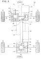
- Fig. 3 is an explanatory diagram showing an embodiment of a driving force transmission device for four-wheel-drive vehicle based on the two-wheel drive of front wheels according to the present invention, and shows a case where the device is applied to a vehicle in which front wheels are driven in the two-wheel-drive mode.
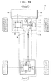
- a driving force transmission device 10 according to the present embodiment is provided in a four-wheel drive vehicle 12, and includes a driving force distribution device 18, a front wheel differential 20 and a rear wheel differential 22.
- the rear wheel differential 22 is connected to the driving force distribution device 18 through a propeller shaft 24.
- the driving force from an engine 14 is changed by a gearbox 16, and input into an input shaft 102 of the driving force distribution device 18 through a drive gear 36 of a gearbox 16 and a ring gear 38 of the front wheel differential 20, and in the two-wheel-drive mode, when a multi-disc clutch mechanism 106 provided coaxially with the input shaft 102 is released, the driving force is not distributed to the rear wheels, but output to the front wheel differential 20 as it is.
- the ring gear 38 drives a left front wheel drive shaft 48 and a right front wheel drive shaft 50 through pinions 40 and 42, and side gears 44 and 46, and the left front wheel drive shaft 48 and the right front wheel drive shaft 50 rotate the a left front wheel 52 and a right front wheel 54 respectively and transmit the driving force to the road surface.
- the front wheel differential 20 absorbs the rotation speed difference, gives a same torque to the left front wheel 52 and the right front wheel 54, and makes the front wheels rotate.
- the ECU first fastens the multi-disc clutch mechanism 106, and then connects a disconnection/connection mechanism 76, thereby the driving force from the multi-disc clutch mechanism 106 is transmitted to a left rear wheel 072 and a right rear wheel 74.
- the driving force output from the rear wheel output shaft 118 is transmitted to a drive pinion 56 of the rear wheel differential 22 through a universal joint 32, a propeller shaft 24, and a universal joint 34, and the drive pinion 56 drives a left rear wheel drive shaft 68 and a right rear wheel drive shaft 70 through a ring gear 58, pinions 60 and 62, side gears 64 and 66, and the left rear wheel drive shaft 68, and the right rear wheel drive shaft 70 rotate the left rear wheel 72 and the right rear wheel 74 respectively and transmits the driving force to the road surface.
- the disconnection/connection mechanism 76 connects the side gear 66 and the right rear wheel drive shaft 70 in the four-wheel drive, and the rotation of the side gear 66 is transmitted to the right rear wheel drive shaft 70 as it is. Even if a rotation speed difference occurs between the left rear wheel 72 and the right rear wheel 74 owing to cornering or changes of the road surface states, the rear wheel differential 22 absorbs the rotation speed difference, gives a same torque to the left rear wheel 72 and the right rear wheel 74, and makes the rear wheels rotate.
- the fastening power of the multi-disc clutch mechanism 106 is controlled continually by a servo motor, and the driving force to be transmitted to the rear wheel output shaft 118 is increased and decreased according to need, thereby the driving force distribution of the front and rear wheels is controlled.
- the ECU When the mode is changed from the four-wheel-drive auto mode to the two-wheel-drive mode, the ECU first releases the multi-disc clutch mechanism 106, and then disconnects the disconnection/connection mechanism 76. In this case, the ECU may first disconnect the disconnection/connection mechanism 76, and then release the multi-disc clutch mechanism 106.
- the disconnection/connection mechanism 76 disconnects the side gear 66 and the right rear wheel drive shaft 70, and prevents the rotation power that the left rear wheel 72 and the right rear wheel 74 receive from the road surface from rotating the ring gear 58.
- the mode may be changed to the two-wheel-drive mode automatically when the four-wheel drive is unnecessary, and on the contrary, the mode may be changed to the four-wheel-drive mode when the four-wheel drive is necessary.
- Fig. 3 it is supposed that the side gear 66 and the right rear wheel drive shaft 70 are connected in the two-wheel-drive mode, for example, when the side gears 64 and 66 rotate in the same direction and at the same speed, the pinion 60 and the pinion 62 do not rotate (rotate on their axes), but the ring gear 58 rotates. Even if there is a rotation speed difference between the side gears 64 and 66, the rotation speed changes if they rotate in the same direction, but the ring gear 58 rotates, and consequently, the drive pinion 56, the universal joint 34, the propeller shaft 24, the universal joint 32, the rear wheel output shaft 118, the output pinion 114, and the bevel gear 112 connected thereto rotate.
- this rear wheel driving force transmission section 78 from the ring gear 58 to the bevel gear 112 is the portion not required to rotate in the two-wheel drive, the rotation of this portion causes viscosity resistance of the oil and friction loss of bearings.
- the driving force that is transmitted from the left front wheel 52 and the right front wheel 54 to the road surface rotates the left rear wheel 72 and the right rear wheel 74, and rotates the rear wheel driving force transmission section 078 not required to rotate in the two-wheel drive, which causes the loss of the driving force and invites the mileage decrease.
- connection between the side gear 66 and the right rear wheel drive shaft 70 is disconnected by the disconnection/connection mechanism 76 in the two-wheel-drive mode, and the dragging torque of the multi-disc clutch mechanism 106 is made smaller than the friction torque of the rear wheel driving force transmission section 78, thereby the rear wheel driving force transmission section 78 is prevented from rotating.
- the fact that the ring gear 58 does not rotate means that the rear wheel driving force transmission section 78 does not rotate, and the loss of the driving force in this case is limited In the parts where the pinion 60, the pinion 62, and the side gear 66 rotate, and accordingly it is possible to improve the mileage more than in the case where there is not the disconnection/connection mechanism 76 and the front wheel driving force transmission section 78 rotates.
- the disconnection/connection mechanism 76 is provided between the side gear 66 in the rear wheel differential 22 and the right rear wheel drive shaft 70, but the disconnection/connection mechanism may be provided in either the inside or the outside of the rear wheel differential 22 as long as it is provided in the position to disconnect/connect the side gear 66 and the left rear wheel drive shaft 70, or the position to disconnect/connect the side gear 64 and the left rear wheel drive shaft 68, or in both of the positions.
- the mechanism may be other mechanism such as a method in which the unit to be constituted by the pinions 60 and 62, the side gears 64 and 66 are separated from the ring gear 58, and the connection thereof is disconnected and connected.
- Figs. 4A and 4B are cross sectional views showing an embodiment of the rear wheel differential 22 in Fig. 3 , where the disconnection/connection mechanism 76 is provided.
- the rear wheel differential 22 includes the ring gear 58 fixed to the external circumferential part of a differential gear case 80, a pinion 60 and a pinion 62 supported rotatably by a pinion shaft 82 fixed to the differential gear case 80, a side gear 64 supported unrotatably by the left rear wheel drive shaft 68 and engaged with the pinion 60 and the pinion 62 in the differential gear case 80, and a side gear 66 supported unrotatably by the side gear shaft 84 and engaged with the pinion 60 and the pinion 62 in the differential gear case 80.
- the rear wheel differential 22 includes a right rear wheel drive shaft 70 whose end 70b engaged with the side gear shaft 84 while not restricted by rotation directions, a sleeve 86 splined to a tooth unit 70a of the right rear wheel drive shaft 70 and a tooth unit 84a of side gear shaft 84 and slidable between the position to connect the right rear wheel drive shaft 70 and the side gear shaft 84 and the position to disconnect them, a fork 88 for sliding the sleeve 86 by an end 88a that is engaged slidably with a groove unit 86a of the sleeve 86, and a shift shaft 90 fixed to the fork 88 and driven in the axial direction by an actuator not shown, and transmits the driving force from the drive pinion 56 engaged with the ring gear 58 in the four-wheel drive to the left rear wheel 72 and the right rear wheel 74.
- the disconnection/connection mechanism 76 in the two-wheel drive is in non-connection state, and the sleeve 86 is not engaged with tooth unit 84a of the side gear shaft 84.
- the rotation of the right rear wheel drive shaft 68 is transmitted to the side gear 66 through the side gear 64, the pinion 60 and the pinion 62, and because the ring gear 58 does not rotate, the side gear shaft 84 is rotated in the direction opposite to the rotation direction of the left rear wheel drive shaft 68.
- Fig. 5 is a cross sectional view showing an embodiment of the driving force distribution device 18 in Fig. 3 .
- the driving force distribution device 18 includes a case 10, and an input shaft 102 that inputs the driving force from the engine 14 into the left side of the case 10 through the gearbox 16, and the ring gear 38 of the front wheel differential 20 is provided, and to the input shaft 102, a right front wheel drive shaft 50 is penetrated rotatably.
- a multi-disc clutch mechanism 106 and a ball cam mechanism 122 are provided coaxially with the input shaft 102, and the multi-disc clutch mechanism 106 fixes a clutch hub 108 to the input shaft 102 and connects a clutch drum 110 to a bevel gear 112 provided rotatably with the bevel gear shaft 116 to the input shaft 102.
- a rear wheel output shaft 118 for outputting the driving force to the rear wheel side is provided in the left bottom of the case 10, and an output pinion 114 is connected to the rear wheel output shaft 118 and engaged with a bevel gear 112.
- An oil pump 184 is provided at the opposite side of the multi-disc clutch mechanism 106 of the ball cam mechanism 122, and gets power from the input shaft 102 and supplies oil to an oil path 186 provided in the input shaft 102.
- the clutch hub 108 and the clutch drum 110 of the multi-disc clutch mechanism 106 are released in the two-wheel drive, and the driving force of the input shaft 102 is not transmitted to the rear wheel output shaft 118.
- the multi-disc clutch mechanism 106 is fastened, and the driving force from the input shaft 102 is transmitted also to the rear wheel output shaft 118 through the multi-disc clutch mechanism 16, the bevel gear 112, and the output pinion 114.
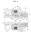
- Fig. 6 is a cross sectional view showing the multi-disc clutch mechanism 106 and the ball cam mechanism 122 in Fig. 5 .
- a ball cam mechanism 122 to control the fastening power of clutch discs 120 provided between the clutch hub 108 and the clutch drum 110 is provided.
- the clutch disc 120 includes spacers 178 for retaining intervals among the clutch discs.
- a ball 140 is sandwiched in ball cam grooves 128 of the cam surfaces of a pair of a fixed cam plate 124 and a rotation cam plate 126 provided relatively rotatably and coaxially with the input shaft 102.
- a retainer 136 having a projection 138 for positioning is provided between the fixed cam plate 124 and the rotation cam plate 126.
- Fig. 7 is an explanatory diagram showing the ball cam mechanism 122 in Fig. 5 viewed from the direction of the oil pump 184.
- a U-shaped end of its expanded arm unit 142 is engaged with the outside of a retaining unit 152a, thereby the rotation is stopped.
- the rotation cam plate 126 includes a plurality of ball cam grooves 128 in its circumferential direction, and a fan type gear 146 formed on the end of its arm unit 44 is engaged with a drive gear 148.
- the servo motor 150 rotates the drive gear 148 through a reduction gear 152.
- a fixed plate 158 is provided in the right side of fixed cam plate 124 through a thrust bearing 154, and a press member 160 is provided in the left side of the rotation cam plate 126 through a thrust bearing 156.
- the press member 160 is urged to the releasing direction of the multi-disc clutch mechanism 106 by a return spring 162 provided between the clutch hub 108 and the press member.
- the ball cam mechanism 122 When the rotation cam plate 126 is driven to rotate in the specified direction by the drive gear 148, the ball cam mechanism 122 receives the press by the ball 140 sandwiched between the ball cam grooves 128 which are the inclined grooves of the facing surfaces and presses the press member 160 and a return spring 162 in the axial direction, and the press member 160 presses the clutch discs 120 of the multi-disc clutch mechanism 106, and thereby the ball cam mechanism increases the transmission torque depending on the rotation amount of the drive gear 148, and becomes its direct connection state at the maximum press position.
- an oil hole opening/closing unit 164 for controlling the supply of the oil to the clutch discs 120 of the multi-disc clutch mechanism 106 from an oil path 186 is provided.
- the oil hole opening/closing unit 164 includes an oil hole 168, an oil hole position adjustment member 166 having a ratchet claw 170, a disc spring 172, a rack 174 provided in the input shaft 102, and a valve 176 provided in the press member 160 to open and close the oil hole 168.
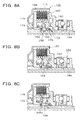
- Figs. 8A to 8C are explanatory diagrams showing the movement of an oil hole opening/closing unit 164 of the multi-disc clutch mechanism 06 in Fig. 5 .
- Fig. 8A shows a state where the multi-disc clutch mechanism 106 is released in the two-wheel drive, and the press member 160 is at standby position most away from the clutch discs 120.
- the oil hole position adjustment member 166 is urged to the right side by the disc spring 172 and regulated by the ratchet claw 170 and the rack 174. In this state, the clutch discs engaged with the clutch drum 110 among the clutch discs 120 do not rotate, but the clutch discs engaged with the clutch hub 108 rotate in conjunction with the rotation of the input shaft 102.
- the valve 176 closes the oil hole 168, and accordingly, the oil from the oil path 186 is not supplied to the clutch discs 120, and the viscosity resistance by the oil is reduced, and thereby, it is possible to prevent the dragging at the side of the clutch drum 110. Further, in the present embodiment, the valve 176 closes the oil hole 168 completely in the state where the multi-disc clutch mechanism 106 in Fig. 8A is released, but at this moment, the valve 176 may not close the oil hole 168 completely, and some amount of oil may be supplied to the clutch discs 120, and the amount may be optionally set in consideration of the lubrication and the cooling of the clutch discs 120.
- Fig. 8B shows the fastening initial state of the multi-disc clutch mechanism 106 on the way of the change from the two-wheel drive to the four-wheel drive, and the press member 160 which is pressed by the ball cam mechanism 122 and moved to the left side is at the position to start the contact to the clutch discs 120. From this point in time, the clutch discs 120 start contacting one another gradually, and by the friction torque thereof, the multi-disc clutch mechanism 106 starts transmitting the driving force to the front wheel side. Because the valve 176 opens the oil hole 68 at this position, the oil is supplied from the oil path 186 to the clutch discs 120 as shown by arrows, and thereby the clutch discs are prevented from being seized.
- FIG. 8C shows the state where the mode is changed into the four-wheel drive, and the multi-disc clutch mechanism 106 is completely fastened, and the press member 160 is at maximum press position where there is not any interval between the clutch discs 120 at all.
- a projection 166a is pressed to the valve 176, and the ratchet claw 170 is engaged with and retained by the rack 174 at the maximum press position of the press member 160.
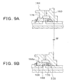
- Fig. 9A and 9B are explanatory diagrams showing the movement of the oil hole position adjustment member 166 of the oil hole opening/closing unit 164 in Figs. 8A to 8C .
- Fig. 9A show the oil hole opening/closing unit 164 in the state where the clutch discs 120 are not abraded or in the initial state of the abrasion
- Fig. 9B shows the oil hole opening/closing unit 164 in the state where the abrasion of the clutch discs 120 progresses.
- the maximum press position of the press member 160 moves to the direction where the clutch stroke becomes deep by the distance roughly same as the total of the decreased disc thickness of all the clutch discs 120, that is, to the left side by a distance W.
- the position where the projection 166a of the oil hole position adjustment member 166 is pressed to the valve 176 changes to the left side, and at the position, the ratchet claw 170 is engaged with the rack 174, and the oil hole position adjustment member 166 is retained.
- the timing of the opening start of the oil hole 168 is not influenced by the abrasion degree of the clutch disc 120, and becomes roughly constant to the intervals among the clutch disc 120, and accordingly it is possible to stabilize the oil supply amount that gives influences to the lubrication, cooling, dragging and the like of the clutch disc 120.
- Fig. 10 is an explanatory diagram showing the setting state of the spacer 178 of the multi-disc clutch mechanism 106 in Fig. 5 .
- Fig. 10 shows the state where the multi-disc clutch mechanism 106 is released in the two-wheel drive, and the press member 160 is at the standby position most away from the clutch disc 120.
- the multi-disc clutch mechanism 106 includes a plurality of clutch discs 120 which can move in the axial direction, and in the clutch discs 120, inside clutch discs 120h are splined to the external circumference of the clutch hub 108, and outside clutch discs 210d are splined to the internal circumference of the clutch drum 110, and, the inside clutch discs 120h and the outside clutch discs 120d are provided alternately.
- Spacers 178 which are plate spring molded of a plate material are provided in the internal circumferential parts of the outside clutch discs 120d, and ensure the intervals among the frictional surfaces not to cause the dragging with the clutch discs 120h at both the adjacent sides.
- the clutch discs 120 can move in the axial direction between a pressed surface 108a of the clutch hub 108 and the pressing surface 160a of the press member 160, and there is an interval E to the press side 160a, meanwhile without the spacers 178, the clutch discs 120 adhere one another by the oil and do not separate, and cause the dragging. Since the spacers 178 ensure the intervals among the frictional surfaces, it is possible to prevent the loss of the driving force owing to the dragging and improve the mileage.
- the value of the interval E at the moment when the press member 160 is at the standby position most away from the clutch discs 120 may not necessarily constant by the states of the intervals among the clutch discs 120.
- the spacers 178 may be provided in the external circumferential parts of the inside clutch discs 120h, but it is preferable to provide the same in the inside with a small torque loss. In other words, with a same frictional resistance by sliding between the clutch discs 120 adjacent to the clutch discs 120 in which the spacers 178 is provided and the spacers 178, the friction torque is smaller when the spacers are provided in the inside, and the friction torque becomes the loss of the driving force. Further, it is preferable that the spring load of the spacers 178 is as small as in the range that the intervals to the adjacent clutch discs 120h can be retained.
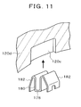
- Fig. 11 is a perspective view showing the spacer in Fig. 10 .
- the spacer 178 is a plate spring molded of a plate material, and includes a sandwiching unit 180 to be inserted into a concave unit 120c provided in the plate thickness direction in the internal circumferential part of the outside clutch disc 120d, and an elastic piece 182 that expands from the sandwiching unit 180 in the outer diameter direction of both the surfaces of the adjacent clutch discs 120 and can be transformed in the axial direction of the clutch discs 120.
- the interval of the sandwiching unit 180 is set narrower than the thickness of concave unit 120c in order to insert and fix the spacer 178 into the concave unit 120c in the direction showed by an arrow.
- Figs. 12A and 12B are cross sectional views showing the spacer 178 of Fig. 10 .
- Fig. 12A shows the state where the multi-disc clutch mechanism 106 is fastened in the four-wheel drive, and the respective frictional surfaces of the outside clutch disc 120d in which the spacer 178 is provided and the inside clutch discs 120h adjacent thereto are closely attached for the rotation.
- Fig. 12B shows the state where the multi-disc clutch mechanism 106 is released in the two-wheel drive, and the respective frictional surfaces of the outside clutch disc 120d in which the spacer 178 is provided and the inside clutch discs 120h adjacent thereto are separated apart to the intervals not to cause the dragging by the spacer 178.
- Figs. 13A and 13B are cross sectional views showing another embodiment of the spacer 178 of the multi-disc clutch mechanism 106 in Fig. 5 .
- the spacer 178 is a plate spring molded of a plate material, and includes a sandwiching unit 180 to be inserted into a concave unit 120c provided in the plate thickness direction in the internal circumferential part of the outside clutch disc 120d, and an elastic piece 182 that expands from the sandwiching unit 1180 in the inner diameter direction of both the surfaces of the adjacent inside clutch discs 120h and can be transformed in the axial direction of the inside clutch discs 120h.
- Fig. 13A shows the state where the multi-disc clutch mechanism 106 is fastened, and the respective frictional surfaces of the outside clutch disc 120d in which the spacer 178 is provided and the inside clutch discs 120h adjacent thereto is closely attached.
- Fig. 13B shows the state where the multi-disc clutch mechanism 106 is released, and the respective frictional surfaces of the outside clutch disc 120d in which the spacer 178 is provided and the inside clutch discs 120h adjacent thereto are separated apart with the intervals not to cause the dragging by the spacer 178.
- Fig. 13A shows the state where the multi-disc clutch mechanism 106 is fastened, and the respective frictional surfaces of the outside clutch disc 120d in which the spacer 178 is provided and the inside clutch discs 120h adjacent thereto is closely attached.
- Fig. 13B shows the state where the multi-disc clutch mechanism 106 is released, and the respective frictional surfaces of the outside clutch disc 120d in which the spacer 178 is provided and the inside clutch discs 120h adjacent thereto are separated apart with the interval
- Figs. 14A to 14C are explanatory diagrams the showing ball cam grooves 128 and a retainer 136 of the ball cam mechanism 122 in Fig. 5 .
- a ball 140 is sandwiched and retained in ball cam grooves 128 in facing cam surfaces of a pair of a fixed cam plate 124 and a rotation cam plate 126.
- the ball cam groove 128 includes an initial area 130 and an inclined area 132 whose cam shapes are different with a runover unit 134 as the border.
- a retainer 136 for retaining the relative position of the ball 140 is provided between the fixed cam plate 124 and the rotation cam plate 126, and the retainer 136 includes a projection 138 for positioning to regulate the initial position of the ball 140 to the ball cam groove 128.
- the projection 138 is engaged with a guide unit 127 formed on the external circumferential part of the rotation cam plate 126.
- Fig. 14A shows the state where the multi-disc clutch mechanism 106 is released in the two-wheel drive, and the press member 160 is at the standby position, and the ball 140 is positioned in the initial area 130 of both the ball cam grooves 128 of the fixed cam plate 124 and the rotation cam plate 126.
- Fig. 14B shows the state where the press member 160 starts contacting the clutch disc 120 in the fastening initial state when the mode shifts from the two-wheel drive to the four-wheel drive, and the ball 140 is at the position shifted from the runover unit 134 to the inclined part 132 of the ball cam grooves 128.
- Fig. 14C shows the state where the mode is changed to the four-wheel drive, the multi-disc clutch mechanism 106 is fastened, and the press member 160 is at the position to press the clutch discs 120, and the ball 140 is positioned at the inclined parts 132 of the ball cam grooves 128.
- a plurality of balls 140 are provided on the circumference in order to disperse the load, there may be a relative displacement among the balls owing to the slide of the ball cam grooves 128 and the balls 140 at the moment of the action of the ball cam mechanism 122, and in that case, it is not possible to press the ball cam grooves 128 equally, and a biased load occurs in the multi-disc clutch mechanism 106 and the surface durability of the ball cam grooves 128 is conspicuously deteriorated.
- the retainer 136 By providing the retainer 136, the relative position of the respective balls 140 is retained, and at every moment the balls return from Fig. 14C to the initial position of Fig. 34A, the initial position of the respective balls 140 to the ball cam grooves 128 are corrected by the projection 138 for the positioning.
- Fig. 15 is a cross sectional view showing another embodiments of the driving force distribution device 18 in Fig. 13 , and the configuration thereof is same as that shown in Figs. 5 and 6 except that a ball cam mechanism 122 is different.
- a servo motor 150 rotates a fringe cam 198 through a reduction gear 152.
- a cam follower 196 including a rotatable roller is provided on the end of an expanded arm unit 144, and the cam follower 196 contacts the external circumferential part of the fringe cam 198.
- the ball cam mechanism 122 When the rotation cam plate 126 is driven to rotate in the specified direction to the fixed cam plate 124 by the fringe cam 198, the ball cam mechanism 122 receives the press by the ball 140 sandwiched between the ball cam grooves 128 which are the inclined grooves of the facing surfaces and presses the press member 160 and a return spring 162 in the axial direction, and the press member 160 presses the clutch discs 120 of the multi-disc clutch mechanism 106, thereby the ball cam mechanism 122 increases the transmission torque depending on the rotation amount of the drive gear 148 and becomes direct connection state at the maximum press position.
- Figs. 16A and 16B are explanatory diagrams showing the ball cam mechanism 122 in Fig. 15 viewed from the input shaft 102.
- the rotation cam plate 126 includes the ball cam grooves 128 in the circumferential direction.
- the ball cam grooves 128 in the present embodiment do not have a runover unit 134 as shown in Figs. 14A to 14C in the embodiment of Fig. 5 , and the inclined area 132 has a shape that goes without a step from the initial area 130.
- the external circumferential part of a cam follower 196 provided on the end of an arm unit 144 expanding from the rotation cam plate 126 contacts the cam surface of a fringe cam 198.
- the cam surface of the fringe cam198 includes an initial area 200, a nonlinear area 1202 and a linear area 206, and rotates clockwise to drive and rotate the rotation cam plate 126 through the cam follower 196, and presses the multi-disc clutch mechanism 106.
- Fig. 16A shows the state where the multi-disc clutch mechanism 106 is released in the two-wheel drive, and the press member 160 is at the standby position and the cam follower 196 is positioned in the initial area 200 of the cam surface of the fringe cam 198.
- Fig. 16B shows the state where the press member 160 starts contacting the clutch disc 120 in the fastening initial state when the mode shifts from the two-wheel drive to the four-wheel drive, and the cam follower 196 is at the position shifting from the nonlinear area 202 to the linear area 206 of the cam surface of the fringe cam 198, and this point becomes the press start position 204.
- the press start position 204 of the fringe cam 198 may be at the nonlinear area 202 or the linear area 206 as long as it is near the position shifting from the nonlinear area 202 to the linear area 206, but it is preferable that the press start position is at a point shifting from the nonlinear area 202 to the linear area 206.
- the shape of the linear cam 1208 without the nonlinear area is shown as a prior-art example and compared with the fringe cam 198.
- an angle ⁇ is required until the press member 160 reaches the press start position 210 to start pressing the clutch disc 120, meanwhile in the fringe cam 198 having the nonlinear area 202, the press member 160 reaches the press start position 204 by an angle a that is far smaller than the angle ⁇ .
- Figs. 17 and 18 are explanatory diagrams showing the movement of the ball cam mechanism 122 shown in Figs. 14A to 14C and Figs. 16A and 16B .
- Fig. 17 is a graph schematically showing the relation between the cam load 188 working to the press member 160 of the multi-disc clutch mechanism 106 and the stroke 190 of the press member 160, and the spring load 192, and the horizontal axis shows the cam angle ( ⁇ ) of the rotation cam plate 126, and the vertical axis shows the cam load (F) and the stroke (S).
- the stroke 190 of the press member 160 shows a nonlinear area from the cam angle ⁇ 0 to ⁇ 1 and a linear area after the cam angle ⁇ 1 to ⁇ max , and the axis of the clutch torque (T) includes its start point (T0) at the spring load 192 of the cam angle ⁇ 1 , and is perpendicular to the inclination of the spring load 192.
- Fig. 18A shows the states of the press member 160, the clutch drum 108, the clutch disc 120 and the return spring 162 corresponding to the cam angle ⁇ shown in Fig. 17 , and the states are the standby state ⁇ 0 , fastening start ⁇ 1 , and fastening state ⁇ n of the multi-disc clutch mechanism 106 respectively.
- Fig. 18B shows the positional relations of the fixed cam plate 124, the rotation cam plate 126 and the ball 140 shown in Figs. 14A to 14C corresponding to the cam angle ⁇ , and the relations show, from the left to the right, the case where the ball 140 of the cam angle ⁇ 0 is at the initial area 130 of the ball cam grooves 128, the case where the ball 140 of the cam angle ⁇ 1 is at the position where the ball 140 of the cam angle ⁇ 1 finishing running over the runover units 134 of the ball cam grooves 128, and the state where the ball 140 of the cam angle ⁇ n is in the inclined area 132 of the ball cam grooves 128 respectively.
- Fig. 18C shows the positional relations of the fringe cam 198 and the cam follower 196 positioned at the end of the arm unit 144 of the rotation cam plate 126 shown in Figs. 16A and 1 6B corresponding to cam angle ⁇ , and the relations show, from the left to the right, the case where the cam follower 196 of the cam angle ⁇ 0 is at the initial area 200 of the fringe cam 198, the case where the cam follower 196 of the cam angle ⁇ 1 is at the press start position 204 of the fringe cam 198, and the case where the cam follower 196 of the cam angle ⁇ n is at the linear area 206 of the fringe cam 198 respectively.
- the movement of the press member 160 is made with a small load only as to press the return spring 162 from the standby position to the position to start contacting the clutch discs 120, but a high speed is necessary in order to take good shift response from the two-wheel drive to the four-wheel drive.
- the movement speed of this section becomes important in particular when the intervals among the clutch discs 120 are made large to prevent the dragging in the two-wheel drive, and the end play of the multi-disc clutch mechanism 106 is made large.
- the standby state of the cam angle ⁇ 0 there is an end play of a distance e between the press member 160 and the clutch discs 120, and in the case of Fig.
- this distance e is quickly shortened in the nonlinear area where the ball 140 runs over the runover unit 134 of the ball cam grooves 128 from the cam angle ⁇ 0 to the cam angle ⁇ 1 .
- the cam follower 196 quickly shorten this distance e by passing the nonlinear area 202 from the cam angle ⁇ 0 to the cam angle ⁇ 1 and moving to the press start position 1204. Because the cam load (F) in the section from the cam angle ⁇ 0 to the cam angle ⁇ 1 is only the spring load 192 of the return spring 162, it is possible to obtain a large stroke S 1 with the small cam angle ⁇ 1 .
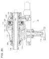
- Fig. 19 is an explanatory diagram showing another embodiment of a driving force transmission device for four-wheel-drive vehicle according to the present invention, and the configuration is same as that in the embodiment shown in Fig. 3 except for an oil pump 194.
- the oil pump 194 is connected to the bevel gear shaft 116, and when the multi-disc clutch mechanism 106 is fastened and the bevel gear 114 rotates, the oil pump 194 supplies the oil to the multi-disc clutch mechanism 106 through a hydraulic pressure circuit not shown to prevents the seizing owing to the frictional heat of the clutch discs in the multi-disc clutch mechanism 106.
- the oil pump 194 is connected to the bevel gear shaft 116 and gets power therefrom, but it may get power from the portions to which the driving force is not transmitted in the two-wheel drive, for example, from the bevel gear 112 or the output pinion 114.
- Fig. 20 is a cross sectional view showing an embodiment of the driving force distribution device 18 in Fig. 19 , and the configuration is same as that of the embodiment shown in Fig. 5 except that there is not the oil pump 184 driven by the input shaft 102, and instead, there is the oil pump 194 driven by the bevel gear shaft 116, and there is not the oil hole opening/closing unit 164 and the oil path 186 whose details are shown in Fig. 6 .
- the oil pump 194 is provided in the opposite side of the bevel gear 112 of the bevel gear shaft 116, and gets power from the bevel gear shaft 116 to supplies the oil to the multi-disc clutch mechanism 106 through the part between the external circumferential part of the input shaft 102 and the inner circumferential part of the bevel gear shaft 116, and the part between the external circumferential part of the input shaft 102 and the inner circumferential part of the bevel gear 112.
- the press member 160 which is pressed by the ball cam mechanism 122 and moves to the left side presses the clutch discs 120, and the clutch discs 120 are contacted one another, since the clutch drum 110 rotates, the bevel gear shaft 116 rotates through the bevel gear 112. Therefore, the oil pump 194 driven by the bevel gear shaft 116 discharges the oil, and the oil is supplied to the clutch discs 120 to prevents the clutch discs from being seized one another.
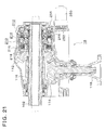
- Fig. 21 is a cross sectional view showing still another embodiment of a driving force transmission device for four-wheel-drive vehicle according to the present invention.
- the embodiment in Fig. 21 substantially shows a driving force distribution device 18 in Fig. 19 , and the configuration is same as that of the cross sectional view shown in Fig. 20 except that a primary clutch 212, a multi-disc clutch mechanism 210 including a ball cam mechanism mechanic 214, an oil hydraulic piston 244, a hydraulic pump 252, and pressure sensor 256 are different.
- the multi-disc clutch mechanism 210, the primary clutch 212, the ball cam mechanism 214 are provided coaxially with the input shaft 102, and the multi-disc clutch mechanism 210 fixes a clutch drum 216 to the input shaft 102, and a clutch hub 218 is connected to a bevel gear 112 rotatably provided to the bevel gear shaft 116 to the input shaft 102.
- a driving force distribution device 18 in the two-wheel drive, the connection between the clutch drum 216 of the multi-disc clutch mechanism 210 and the clutch hub 218 is released, and the driving force of the input shaft 102 is not transmitted to the rear wheel output shaft 118.
- the multi-disc clutch mechanism 210 is fastened, and the driving force from the input shaft 102 is transmitted also transmitted to the rear wheel output shaft 118 through the multi-disc clutch mechanism 210, the bevel gear 112, and the output pinion 114.
- Fig. 22 is a cross sectional view showing the multi-disc clutch mechanism 210, the primary clutch 212 and the cam mechanism 214.
- a ball cam mechanism 214 to control the fastening power of the clutch discs 220 provided between the clutch drum 216 and the clutch hub 218 and a primary clutch 212 for driving the ball cam mechanism 214 are provided.
- the ball cam mechanism 214 sandwiches and retains a ball 228 in ball cam grooves 226 of the cam surfaces of a pair of a press member 222 and a cam plate 224 provided relatively rotatably and coaxially with the input shaft 102.
- the press member 222 is urged to the releasing direction of the multi-disc clutch mechanism 210 by a return spring 230 rotates together with the clutch hub 218 and provided between the clutch hub 218 and the press member.
- a thrust bearing 232 is provided between the cam plate 224 and the clutch drum 216.
- the primary clutch 212 includes a clutch disc 234 between the clutch drum 216 and the cam plate 224, and transmits the rotation of the clutch drum 216 to the cam plate 224 when a press disc 236 presses and fastens the clutch disc 234.
- the press disc 236 connects with a pressure receive disc 240 through a press shaft 238 penetrate through the clutch drum 216, and the pressure receive disc 240 is engaged with a hydraulic piston 244 through a thrust bearing 242.
- the hydraulic piston 244 can move between the position to release the primary clutch 212 and the position to fasten the same in a cylinder 246, and is sealed with an O-ring 248.
- the servo motor 250 drives a hydraulic pump 252, and the oil discharged from the hydraulic pump 252 flows into a cylinder 246 through an oil path 254, thereby the hydraulic piston 244 presses the clutch disc 234 through the thrust bearing 242, the pressure receive disc 240, the press shaft 238, and the press disc 236, and fastens the primary clutch 212.
- a hydraulic sensor 256 is provided and detects the hydraulic pressure of the hydraulic cylinder 246.
- a hydraulic pressure controlling unit not shown monitors the hydraulic pressure detected by the hydraulic sensor 256 and controls the hydraulic piston 244 to an appropriate movement amount.
- the ball cam mechanism 214 When the cam plate 224 is driven to rotate in a specified direction to the press member 222 by the primary clutch 212, the ball cam mechanism 214 receives the press by the ball 228 sandwiched between the ball cam grooves 226 which are the inclined grooves of the facing surfaces and presses the press member 222 and a return spring 230 in the axial direction, and the press member 222 presses the clutch discs 220 of the multi-disc clutch mechanism 210, thereby the ball cam mechanism 214 increases the transmission torque depending on the movement amount of the hydraulic piston 244 and becomes direct connection state at the maximum press position.
- the configuration having the primary clutch 212 as mentioned above, it is possible to reduce the number of the clutch discs 220 and to decrease the dragging torque of the multi-disc clutch mechanism 210.
- By making the dragging torque smaller than the friction torque of the rear wheel driving force transmission section it is possible to stop the rotation of the structural elements in the rear wheel driving force transmission section to decrease the oil viscosity resistance and the friction loss in this section, and prevent the
- the present invention is not limited to the embodiment mentioned above, but includes an arbitrary modification not impair the object and advantage thereof, and further the present invention is not limited to the values indicated in the above embodiments.
Abstract
Description
- This application is a priority based on prior application No.
JP 2008-63902, filed March 13, 2008 - The present invention relates to a driving force transmission device for four-wheel-drive vehicle based on the two-wheel drive of front wheels enabling to change a two-wheel drive and a four-wheel drive, more specifically, to a driving force transmission device for four-wheel-drive vehicle in which the rotation of the parts not operative for the transmission of the driving force in the two-wheel drive is stopped.
- As one of driving force transmission devices for four-wheel-drive vehicle in which front wheels are driven in the two-wheel drive, and the distribution control of the driving force to the rear wheels is performed in the four-wheel drive by a multi-disc clutch mechanism, in the four-wheel-drive vehicle based on the two-wheel drive of conventional so-called on-demand type full-time front wheels, for example, the device shown in
Fig. 1 is known. -
Fig. 1 shows a driving force transmission device for four-wheel-drive vehicle based on the two-wheel drive of conventional so-called on-demand type full-time front wheels. InFig. 3 , a drivingforce transmission device 300 is provided in a four-wheel-drive vehicle 302, and the driving force from anengine 304 is changed by agearbox 306 and input into afront wheel differential 308 and a driving forcedirection converting unit 310 in the drivingforce transmission device 300, and the output from the driving forcedirection converting unit 310 is transmitted to amulti-disc clutch mechanism 314 through apropeller shaft 312. When themulti-disc clutch mechanism 314 is released (disconnected) in the two-wheel drive, the driving force is not distributed to arear wheel differential 324 but transmitted to thefront wheel differential 308, and thefront wheel differential 308 absorbs the rotation speed difference between a leftfront wheel 316 and a rightfront wheel 318, gives a same torque to theleft front wheel 316 and the rightfront wheel 318, and makes the front wheels rotate. When themulti-disc clutch mechanism 314 is fastened (connected) in the four-wheel drive, the driving force is transmitted also to therear wheel differential 324 through adrive pinion 320 connected to themulti-disc clutch mechanism 314 and aring gear 322, and therear wheel differential 324 absorbs the rotation speed difference between a leftrear wheel 326 and a rightrear wheel 328, gives a same torque to the leftrear wheel 326 and the rightrear wheel 328, and makes the rear wheels rotate. In general, in the on-demand type full-time four-wheel-drive vehicle, as the drive modes for the drivers to optionally select by switch operations, a two-wheel-drive mode, a four-wheel-drive auto mode, and a four-wheel-drive lock mode are prepared. The two-wheel-drive mode is the mode that is used in the two-wheel-drive state in which themulti-disc clutch mechanism 314 of the drivingforce transmission device 300 is released, and selected when to show the maximum running performance on dry pavement roads and the like on which the driving force by four wheels is not necessary for the best mileage. The four-wheel-drive auto mode is the mode in which various running vehicle states are detected by sensors, and the driving force distribution of themulti-disc clutch mechanism 314 to the front and rear wheels are automatically controlled at the most suitable state by an ECU (Electronic Control Unit) based on the detection signals of the sensor, and can be always selected regardless of road surface states. In this mode, the fastening power of themulti-disc clutch mechanism 314 is increased and/or decreased continually by an actuator, and the driving force distribution to the front and rear wheels is controlled between the two-wheel-drive state in which the driving force to the rear wheels is approximately zero and the maximum fastening power. The four-wheel-drive lock mode is the mode in which the fastening power of themulti-disc clutch mechanism 314 is retained at its maximum regardless of the vehicle states detected by the various sensors, and this mode is selected when to show running characteristics as the four-wheel drive on rough roads and the like at the maximum. However, in such a conventional driving force transmission device for four-wheel-drive vehicle based on the two-wheel drive of front wheels, even in the two-wheel-drive mode, since the driving force from thegearbox 306 makes a driving forcedirection converting unit 310, apropeller shaft 312 and the driving side (front wheel side) of themulti-disc clutch mechanism 314 rotates, and the leftrear wheel 326 and the rightrear wheel 328 and therear wheel differential 324 are directly connected, the leftrear wheel 326 and the rightrear wheel 328 rotate, and consequently, therear wheel differential 324, thedrive pinion 320 and the driven side (rear wheel side) of themulti-disc clutch mechanism 314 also rotate. That is, even in the two-wheel drive in which themulti-disc clutch mechanism 314 is released and the driving force is not transmitted to the rear wheels, and even if themulti-disc clutch mechanism 314 is released completely, the respective structural elements in the rear wheel drivingforce transmission section 330 including the driving forcedirection converting unit 310, thepropeller shaft 312, themulti-disc clutch mechanism 314, thedrive pinion 320 and therear wheel differential 324 rotate, and this leads to a mileage fall by stirring resistance of the oil in this section or friction loss of bearings, which has been still another problem in the prior art. Further, themulti-disc clutch mechanism 314 includes a plurality of clutch discs, and although these clutch discs are lubricated and cooled by oil, since the so-called dragging torque that occurs by the viscosity resistance of the oil arising from the rotation speed difference between the driving side and the driven side of the clutch discs and the friction loss by the contact between the clutch discs is larger than the friction torque of thedrive pinion 320 and therear wheel differential 324, even if the leftrear wheel 326 and the rightrear wheel 328 and therear wheel differential 324 are disconnected, thedrive pinion 320 and therear wheel differential 324 are rotated by themulti-disc clutch mechanism 314, and this deteriorates the mileage, which has been yet another problem in the prior art. In order to decrease this dragging torque, if the supply of the oil to themulti-disc clutch mechanism 314 is stopped, or if the multi-disc clutch mechanism is used with an extremely reduced quantity of the oil, it is possible to decrease or eliminate the dragging torque that occurs by the viscosity resistance of the oil. However, there is a fear that themulti-disc clutch mechanism 314 may be seized if sufficient lubrication is not performed at the time of the driving force distribution control. Furthermore, as a method to ensure sufficient intervals among the respective clutch discs in the released state of themulti-disc clutch mechanism 314, a method is suggested in which aring spring 332 formed in a wave shape in the circumferential direction as shown inFig. 2 is put between adjacent clutch discs of the driving side or adjacent clutch discs of the driven side, however, according to this method, it is possible to ensure the sufficient intervals between the clutch discs of the driving side or the clutch discs of the driven side, but it is not possible to prevent the clutch discs of the driving side from contacting the clutch discs of the driven side. In the four-wheel-drive auto mode, the driving force is transmitted to therear wheels force transmission section 330, and consequently, the mileage becomes worse than that at the time of the two-wheel-drive mode. In this mode, the driving force distribution is automatically controlled at the most suitable state even if the driver does not perform any operation, however, in the driving condition that does not need the four-wheel drive such as running on dry pavement roads, when the driver forgets the switch change to the two-wheel-drive mode, the running is continues in a poor mileage state, which has been yet another problem in the prior art. In this case, by switching over the two-wheel-drive mode and the four-wheel-drive auto mode automatically depending on driving conditions, it is possible to improve the mileage regardless of the switch operation by the driver, but for that purpose, it is necessary to quickly change the two-wheel drive and the four-wheel drive. As another method to decrease the dragging torque of themulti-disc clutch mechanism 314, there may be a method in which the distance of the approach section shifting from the standby state at the time of the two-wheel drive to the fastening state at the time of the four-wheel drive of themulti-disc clutch mechanism 314, that is, the so-called end play, is made large, and the intervals among the respective clutch discs are ensured sufficiently in the state in which themulti-disc clutch mechanism 314 is released at the time of the two-wheel drive, thereby the clutch discs are prevented from contacting one another. However, when the end play is made large, it takes much time in changing the mode from the two-wheel drive to the four-wheel drive, which decreases the running performance. - According to the present invention is to provide a driving force transmission device for four-wheel-drive vehicle which is based on the two-wheel drive of front wheels, and does not sacrifice the change response from the two-wheel drive to the four-wheel drive, decreases the oil viscosity resistance and friction loss owing to the rotation of the rear wheel differential and the driving force distribution device in the two-wheel drive, and does not deteriorate the mileage.
- According to an aspect of the present invention, there is provided a driving force transmission device for four-wheel-drive vehicle based on a two-wheel drive of front wheels, including:
- a switch mechanism for switching between a four-wheel-drive mode in which the fastening power of a multi-disc clutch mechanism is changed continually and the driving force distribution to front and rear wheels is controlled automatically depending on running conditions, and a two-wheel-drive mode in which the multi-disc clutch mechanism is released and the driving force is transmitted to only the rear wheels;
- a front wheel differential for inputting a driving force from a drive source and outputting the driving force to left and right front wheel drive shafts and the multi-disc clutch mechanism;
- a propeller shaft for transmitting the driving force distributed by the multi-disc clutch mechanism;
- a rear wheel differential for inputting the driving force from the propeller shaft and outputting the driving force to left and right rear wheel drive shafts; and
- a disconnection/connection mechanism for disconnecting and connecting the rear wheel differential and one or both of the left and right rear wheel drive shafts, wherein
- the dragging torque of the multi-disc clutch mechanism is made smaller than the rotation resistance of a rear wheel driving force transmission section from the multi-disc clutch mechanism to the disconnection/connection mechanism in the two-wheel-drive mode, and the rear wheel differential and one or both of the left and right rear wheel drive shafts are disconnected by the disconnection/connection mechanism, thereby the rotation of the rear wheel driving force transmission section is stopped.
- Herein, the multi-disc clutch mechanism includes a plurality of clutch discs that can be displaced in the axial direction of the multi-disc clutch mechanism, and a lubricating oil supply amount change mechanism to control the supply amount of lubricating oil to the clutch discs, and stops or limit the supply of the lubricating oil to the clutch discs to a specified amount by the lubricating oil supply amount change mechanism at the time when the multi-disc clutch mechanism is released, and makes the total of the intervals among the clutch discs above a specified value to make the dragging torque by the lubricating oil of the multi-disc clutch mechanism smaller than the rotation resistance of the rear wheel driving force transmission section.
- Further, the multi-disc clutch mechanism includes spacers to urge in the direction to widen the intervals among the clutch discs, and the spacer is a plate spring member having a sandwiching unit to be inserted into a concave unit in the disc thickness direction provided in the circumferential part of the clutch disc, and an elastic piece that expands from the sandwiching unit to the radial direction of both the surfaces of the clutch disc and is deformable in the axial direction of the clutch disc, furthermore, the plate spring member is provided in the internal circumferential part of the clutch disc, and in the plate spring member, the elastic piece is opened in the external circumferential direction of the clutch disc.
- The lubricating oil supply amount change mechanism includes an oil pump that is driven in conjunction with the output to the front wheels and supplies lubricating oil to the clutch discs, a press member that moves in the axial direction to fasten and release the clutch discs, and an oil hole opening/closing unit that opens and closes an oil hole to supply the lubricating oil to the clutch discs in conjunction with the press member and controls the flow amount of the lubricating oil, and the oil hole opening/closing unit closes the oil hole at the position where the clutch discs are released, and opens the oil hole at the position where the clutch discs are fastened.
- The oil hole opening/closing unit includes an oil hole position adjustment member that changes the positions of the oil hole to supply the lubricating oil to the clutch discs in conjunction with the movement limit in the fastening direction of the above press member which changes depending on the abrasion of the clutch discs.
- Further, the multi-disc clutch mechanism includes a press member that moves in the axial direction to fasten and release the clutch discs, a drive source that outputs a rotation power to move the press member, and a press mechanism that converts and amplifies the rotation power from the drive source to the fastening direction of the press member, and the conversion rate to the axial direction displacement of the press member to the rotation angle of the drive source is higher in a shift section where the press member moves from the standby position in the releasing direction to the fastening start position in the fastening direction than in a press section where the fastening power is changed continually from the fastening start position to the fastening end position in the fastening direction.
- The press member includes a ball cam mechanism in which the ball cam grooves expanding in the circumferential direction on facing surfaces of a fixed cam plate and a rotation cam plate provided coaxially with the press mechanism are provided and balls are sandwiched between the ball cam grooves, and the ball cam grooves have a nonlinear area to move the press member in the shift section, and a linear area to move the press member in the press section, and the displacement in the axial direction to the rotation angle of the rotation cam plate is larger in the nonlinear area than in the linear area.
- The ball cam mechanism includes a retainer to retain the relative positions of the respective balls provided in the circumferential direction, and the retainer includes a positioning unit to regulate the initial positions of the balls to the ball cam grooves.
- Further, the press mechanism includes a rotation cam plate provided coaxially with the press member to convert a rotation displacement into an axial direction displacement, a fringe cam having a cam surface in the circumferential direction and driven to rotate by the drive source, and a cam follower to be engaged with the fringe cam at the end of an arm unit expanding from the rotation cam plate, and the cam surface includes a nonlinear area to move the press member in the shift section, and a linear area to move the press member in the press section, and the normal direction displacement of the cam follower to the rotation angle of the fringe cam is larger in the nonlinear area than in the linear area.
- Alternatively, the multi-disc clutch mechanism includes a press member for moving in the axial direction to fasten and release the clutch discs, a primary clutch for transmitting the output to the front wheels to the press member, an actuator for moving in the axial direction to fasten and release the primary clutch, and a press mechanism that converts and amplifies the rotation power from the primary clutch to the fastening direction of the press member.
- According to the present invention, in two-wheel-drive mode, the rear wheel differential and one or both of the left and right rear wheel drive shafts are disconnected by the disconnection/connection mechanism and the rotation of the ring gear of the rear wheel differential accompanying the rotation of the rear wheels is restrained, and the intervals among the clutch discs of the multi-disc clutch mechanism are ensured by the spacers, the supply of the oil to the clutch discs is limited, and the dragging torque of the multi-disc clutch mechanism is made smaller than the friction torque of the rear wheel driving force transmission section, thereby, it is possible to stop the rotation of the structural elements of the rear wheel driving force transmission section, decrease the oil viscosity resistance and the friction loss in this section, and prevent the mileage from decreasing.
- Furthermore, even when the end play is made large to ensure the interval of the clutch discs, the press mechanism is provided to move the press member faster in the approach section where the press member contacts or comes close to the clutch disc than in the press section thereafter, thereby, it is possible to prevent the mileage from decreasing, while not sacrificing the change response from the two-wheel drive to the four-wheel drive. The above and other objects, features, and advantages of the present invention will become more apparent from the following detailed description with reference to the drawings.
-
-
Fig. 1 is an explanatory diagram showing a conventional driving force transmission device for four-wheel-drive vehicle based on the two-wheel drive of front wheels; -
Fig. 2 is an explanatory diagram showing a dragging prevention ring spring of a conventional multi-disc clutch mechanism; -
Fig. 3 is an explanatory diagram showing an embodiment of a driving force transmission device for four-wheel-drive vehicle based on the two-wheel drive of front wheels according to the present invention; -
Figs. 4A and 4B are cross sectional views showing an embodiment of the front wheel differential inFig. 3 ; -
Fig. 5 is a cross sectional view showing an embodiment of the driving force distribution device inFig. 3 ; -
Fig. 6 is a cross sectional view showing the multi-disc clutch mechanism and the ball cam mechanism inFig. 5 ; -
Fig. 7 is an explanatory diagram showing the ball cam mechanism inFig. 5 viewed from the axial direction; -
Figs. 8A to 8C are explanatory diagrams showing the movement of the oil hole opening/closing unit of the multi-disc clutch mechanism inFig. 5 ; -
Figs. 9A and 9B are explanatory diagrams showing the movement of the oil hole position adjustment member of the oil hole opening/closing unit inFig. 8 ; -
Fig. 10 is an explanatory diagram showing the spacer setting state of the multi-disc clutch mechanism inFig. 5 ; -
Fig. 11 is a perspective view showing the spacer inFig. 10 ; -
Figs. 12A and 12B are cross sectional views showing the spacer inFig. 10 ; -
Figs. 13A and 13B are cross sectional views showing another embodiment of the spacer of the multi-disc clutch mechanism inFig. 5 ; -
Figs. 14A to 14C are explanatory diagrams showing the ball cam grooves and the retainer of the ball cam mechanism inFig. 5 ; -
Fig. 15 is a cross sectional view showing another embodiment of the driving force distribution device inFig. 13 ; -
Figs. 16A and 16B are explanatory diagrams showing the ball cam mechanism inFig. 5 viewed from the axial direction; -
Fig. 17 is an explanatory diagram showing the movement of the ball cam mechanism shown inFig. 15 andFig. 16 ; -
Figs. 18A to 18C are explanatory diagrams showing the movement of the ball cam mechanism shown inFig. 15 andFig. 16 ; -
Fig. 19 is an explanatory diagram showing another embodiment of a driving force transmission device for four-wheel-drive vehicle according to the present invention; -
Fig. 20 is a cross sectional view showing an embodiment of the driving force distribution device inFig. 19 ; -
Fig. 21 is an explanatory diagram showing still another embodiment of a driving force transmission device for four-wheel-drive vehicle according to the present invention; and -
Fig. 22 is a cross sectional view showing the primary clutch and the ball cam mechanism shown inFig. 21 . -
Fig. 3 is an explanatory diagram showing an embodiment of a driving force transmission device for four-wheel-drive vehicle based on the two-wheel drive of front wheels according to the present invention, and shows a case where the device is applied to a vehicle in which front wheels are driven in the two-wheel-drive mode. InFig. 3 , a drivingforce transmission device 10 according to the present embodiment is provided in a four-wheel drive vehicle 12, and includes a drivingforce distribution device 18, a front wheel differential 20 and arear wheel differential 22. The rear wheel differential 22 is connected to the drivingforce distribution device 18 through apropeller shaft 24. The driving force from anengine 14 is changed by agearbox 16, and input into aninput shaft 102 of the drivingforce distribution device 18 through adrive gear 36 of agearbox 16 and aring gear 38 of the front wheel differential 20, and in the two-wheel-drive mode, when a multi-discclutch mechanism 106 provided coaxially with theinput shaft 102 is released, the driving force is not distributed to the rear wheels, but output to the front wheel differential 20 as it is. Thering gear 38 drives a left frontwheel drive shaft 48 and a right frontwheel drive shaft 50 throughpinions wheel drive shaft 48 and the right frontwheel drive shaft 50 rotate the aleft front wheel 52 and a rightfront wheel 54 respectively and transmit the driving force to the road surface. Even if a rotation speed difference occurs between theleft front wheel 52 and theright front wheel 54 owing to cornering or changes of the road surface states, the front wheel differential 20 absorbs the rotation speed difference, gives a same torque to theleft front wheel 52 and theright front wheel 54, and makes the front wheels rotate. When the driver changes the mode from the two-wheel-drive mode to the four-wheel-drive auto mode, the ECU first fastens the multi-discclutch mechanism 106, and then connects a disconnection/connection mechanism 76, thereby the driving force from the multi-discclutch mechanism 106 is transmitted to a left rear wheel 072 and a rightrear wheel 74. The driving force output from the rearwheel output shaft 118 is transmitted to adrive pinion 56 of the rear wheel differential 22 through auniversal joint 32, apropeller shaft 24, and auniversal joint 34, and thedrive pinion 56 drives a left rearwheel drive shaft 68 and a right rearwheel drive shaft 70 through aring gear 58, pinions 60 and 62, side gears 64 and 66, and the left rearwheel drive shaft 68, and the right rearwheel drive shaft 70 rotate the leftrear wheel 72 and the rightrear wheel 74 respectively and transmits the driving force to the road surface. The disconnection/connection mechanism 76 connects theside gear 66 and the right rearwheel drive shaft 70 in the four-wheel drive, and the rotation of theside gear 66 is transmitted to the right rearwheel drive shaft 70 as it is. Even if a rotation speed difference occurs between the leftrear wheel 72 and the rightrear wheel 74 owing to cornering or changes of the road surface states, the rear wheel differential 22 absorbs the rotation speed difference, gives a same torque to the leftrear wheel 72 and the rightrear wheel 74, and makes the rear wheels rotate. The fastening power of the multi-discclutch mechanism 106 is controlled continually by a servo motor, and the driving force to be transmitted to the rearwheel output shaft 118 is increased and decreased according to need, thereby the driving force distribution of the front and rear wheels is controlled. When the mode is changed from the four-wheel-drive auto mode to the two-wheel-drive mode, the ECU first releases the multi-discclutch mechanism 106, and then disconnects the disconnection/connection mechanism 76. In this case, the ECU may first disconnect the disconnection/connection mechanism 76, and then release the multi-discclutch mechanism 106. The disconnection/connection mechanism 76 disconnects theside gear 66 and the right rearwheel drive shaft 70, and prevents the rotation power that the leftrear wheel 72 and the rightrear wheel 74 receive from the road surface from rotating thering gear 58. Thereby, it is possible to solve the problem that the rear wheel drivingforce transmission section 78 from thering gear 58 to thebevel gear 112 rotates even in the two-wheel drive in which the rear wheels are not driven, which is a factor to cause a mileage decrease in the two-wheel drive. Further, even if the driver does not operate the changeover switch, by the judgment of the ECU to detect the vehicle state, the mode may be changed to the two-wheel-drive mode automatically when the four-wheel drive is unnecessary, and on the contrary, the mode may be changed to the four-wheel-drive mode when the four-wheel drive is necessary. - In
Fig. 3 , it is supposed that theside gear 66 and the right rearwheel drive shaft 70 are connected in the two-wheel-drive mode, for example, when the side gears 64 and 66 rotate in the same direction and at the same speed, thepinion 60 and thepinion 62 do not rotate (rotate on their axes), but thering gear 58 rotates. Even if there is a rotation speed difference between the side gears 64 and 66, the rotation speed changes if they rotate in the same direction, but thering gear 58 rotates, and consequently, thedrive pinion 56, theuniversal joint 34, thepropeller shaft 24, theuniversal joint 32, the rearwheel output shaft 118, theoutput pinion 114, and thebevel gear 112 connected thereto rotate. Although this rear wheel drivingforce transmission section 78 from thering gear 58 to thebevel gear 112 is the portion not required to rotate in the two-wheel drive, the rotation of this portion causes viscosity resistance of the oil and friction loss of bearings. In other words, the driving force that is transmitted from theleft front wheel 52 and theright front wheel 54 to the road surface rotates the leftrear wheel 72 and the rightrear wheel 74, and rotates the rear wheel driving force transmission section 078 not required to rotate in the two-wheel drive, which causes the loss of the driving force and invites the mileage decrease. Therefore, in the present invention, the connection between theside gear 66 and the right rearwheel drive shaft 70 is disconnected by the disconnection/connection mechanism 76 in the two-wheel-drive mode, and the dragging torque of the multi-discclutch mechanism 106 is made smaller than the friction torque of the rear wheel drivingforce transmission section 78, thereby the rear wheel drivingforce transmission section 78 is prevented from rotating. When the connection between the side gear 066 and the right rearwheel drive shaft 70 is disconnected, the rotation of the rightrear wheel 74 is not transmitted to theside gear 66, and therefore, the rotation of theside gear 64 by the leftrear wheel 72 can rotate theside gear 66 through thepinion 60 and thepinion 62 in the opposite direction, and since the rotation resistance from thedrive pinion 56 connected to thering gear 58 to thebevel gear 112 is larger than the rotation resistance of thepinion 60, thepinion 62, and theside gear 66, thering gear 58 does not rotate. The fact that thering gear 58 does not rotate means that the rear wheel drivingforce transmission section 78 does not rotate, and the loss of the driving force in this case is limited In the parts where thepinion 60, thepinion 62, and theside gear 66 rotate, and accordingly it is possible to improve the mileage more than in the case where there is not the disconnection/connection mechanism 76 and the front wheel drivingforce transmission section 78 rotates. Further, in the present embodiment, the disconnection/connection mechanism 76 is provided between theside gear 66 in the rear wheel differential 22 and the right rearwheel drive shaft 70, but the disconnection/connection mechanism may be provided in either the inside or the outside of the rear wheel differential 22 as long as it is provided in the position to disconnect/connect theside gear 66 and the left rearwheel drive shaft 70, or the position to disconnect/connect theside gear 64 and the left rearwheel drive shaft 68, or in both of the positions. Furthermore, the mechanism may be other mechanism such as a method in which the unit to be constituted by thepinions ring gear 58, and the connection thereof is disconnected and connected. -
Figs. 4A and 4B are cross sectional views showing an embodiment of the rear wheel differential 22 inFig. 3 , where the disconnection/connection mechanism 76 is provided. InFig. 4A and 24B, the rear wheel differential 22 includes thering gear 58 fixed to the external circumferential part of adifferential gear case 80, apinion 60 and apinion 62 supported rotatably by apinion shaft 82 fixed to thedifferential gear case 80, aside gear 64 supported unrotatably by the left rearwheel drive shaft 68 and engaged with thepinion 60 and thepinion 62 in thedifferential gear case 80, and aside gear 66 supported unrotatably by theside gear shaft 84 and engaged with thepinion 60 and thepinion 62 in thedifferential gear case 80. Furthermore, the rear wheel differential 22 includes a right rearwheel drive shaft 70 whoseend 70b engaged with theside gear shaft 84 while not restricted by rotation directions, asleeve 86 splined to atooth unit 70a of the right rearwheel drive shaft 70 and atooth unit 84a ofside gear shaft 84 and slidable between the position to connect the right rearwheel drive shaft 70 and theside gear shaft 84 and the position to disconnect them, afork 88 for sliding thesleeve 86 by anend 88a that is engaged slidably with agroove unit 86a of thesleeve 86, and ashift shaft 90 fixed to thefork 88 and driven in the axial direction by an actuator not shown, and transmits the driving force from thedrive pinion 56 engaged with thering gear 58 in the four-wheel drive to the leftrear wheel 72 and the rightrear wheel 74. - In
Fig. 4A , the disconnection/connection mechanism 76 in the two-wheel drive is in non-connection state, and thesleeve 86 is not engaged withtooth unit 84a of theside gear shaft 84. The rotation of the right rearwheel drive shaft 68 is transmitted to theside gear 66 through theside gear 64, thepinion 60 and thepinion 62, and because thering gear 58 does not rotate, theside gear shaft 84 is rotated in the direction opposite to the rotation direction of the left rearwheel drive shaft 68. - In
Fig. 4B , in the state where thefork 88 moves to the L direction in the four-wheel drive, and the disconnection/connection mechanism 76 is connected thereto, thesleeve 86 is engaged with thetooth unit 84a of theside gear shaft 84. Thering gear 58 rotates by thedrive pinion 56, and rotates the left rearwheel drive shaft 68 and the right rearwheel drive shaft 70 in the same direction. When the mode is changed back to the two-wheel drive, thefork 88 moves in the U direction, and the disconnection/connection mechanism 76 is changed back to the non-connection state. As another factor to cause the mileage decrease in the two-wheel-drive mode, there is the problem that the rear wheel drivingforce transmission section 78 rotates because the so-called dragging torque that occurs by the viscosity resistance of the oil arising from the rotation speed difference between the driving side (rear-wheel side) and the driven side (front-wheel side) of the clutch discs provided to the multi-discclutch mechanism 106 and the friction loss by the contact between the clutch discs is larger than the friction torque of the rear wheel drivingforce transmission section 78. -
Fig. 5 is a cross sectional view showing an embodiment of the drivingforce distribution device 18 inFig. 3 . InFig. 5 , the drivingforce distribution device 18 includes acase 10, and aninput shaft 102 that inputs the driving force from theengine 14 into the left side of thecase 10 through thegearbox 16, and thering gear 38 of the front wheel differential 20 is provided, and to theinput shaft 102, a right frontwheel drive shaft 50 is penetrated rotatably. A multi-discclutch mechanism 106 and aball cam mechanism 122 are provided coaxially with theinput shaft 102, and the multi-discclutch mechanism 106 fixes aclutch hub 108 to theinput shaft 102 and connects aclutch drum 110 to abevel gear 112 provided rotatably with thebevel gear shaft 116 to theinput shaft 102. Perpendicular to theinput shaft 102, a rearwheel output shaft 118 for outputting the driving force to the rear wheel side is provided in the left bottom of thecase 10, and anoutput pinion 114 is connected to the rearwheel output shaft 118 and engaged with abevel gear 112. Anoil pump 184 is provided at the opposite side of the multi-discclutch mechanism 106 of theball cam mechanism 122, and gets power from theinput shaft 102 and supplies oil to anoil path 186 provided in theinput shaft 102. In such a drivingforce distribution device 18, theclutch hub 108 and theclutch drum 110 of the multi-discclutch mechanism 106 are released in the two-wheel drive, and the driving force of theinput shaft 102 is not transmitted to the rearwheel output shaft 118. In the four-wheel drive, the multi-discclutch mechanism 106 is fastened, and the driving force from theinput shaft 102 is transmitted also to the rearwheel output shaft 118 through the multi-discclutch mechanism 16, thebevel gear 112, and theoutput pinion 114. -
Fig. 6 is a cross sectional view showing the multi-discclutch mechanism 106 and theball cam mechanism 122 inFig. 5 . InFig. 6 , to the multi-discclutch mechanism 106, aball cam mechanism 122 to control the fastening power ofclutch discs 120 provided between theclutch hub 108 and theclutch drum 110 is provided. Theclutch disc 120 includesspacers 178 for retaining intervals among the clutch discs. In theball cam mechanism 122, aball 140 is sandwiched inball cam grooves 128 of the cam surfaces of a pair of a fixedcam plate 124 and arotation cam plate 126 provided relatively rotatably and coaxially with theinput shaft 102. Furthermore, aretainer 136 having aprojection 138 for positioning is provided between the fixedcam plate 124 and therotation cam plate 126. -
Fig. 7 is an explanatory diagram showing theball cam mechanism 122 inFig. 5 viewed from the direction of theoil pump 184. InFig. 7 , in the fixedcam plate 124, a U-shaped end of its expandedarm unit 142 is engaged with the outside of aretaining unit 152a, thereby the rotation is stopped. Therotation cam plate 126 includes a plurality ofball cam grooves 128 in its circumferential direction, and afan type gear 146 formed on the end of itsarm unit 44 is engaged with adrive gear 148. With reference toFigs. 5 and 26 again, theservo motor 150 rotates thedrive gear 148 through areduction gear 152. A fixedplate 158 is provided in the right side of fixedcam plate 124 through athrust bearing 154, and apress member 160 is provided in the left side of therotation cam plate 126 through athrust bearing 156. Thepress member 160 is urged to the releasing direction of the multi-discclutch mechanism 106 by areturn spring 162 provided between theclutch hub 108 and the press member. When therotation cam plate 126 is driven to rotate in the specified direction by thedrive gear 148, theball cam mechanism 122 receives the press by theball 140 sandwiched between theball cam grooves 128 which are the inclined grooves of the facing surfaces and presses thepress member 160 and areturn spring 162 in the axial direction, and thepress member 160 presses theclutch discs 120 of the multi-discclutch mechanism 106, and thereby the ball cam mechanism increases the transmission torque depending on the rotation amount of thedrive gear 148, and becomes its direct connection state at the maximum press position. In the part surrounded by theinput shaft 102, theclutch hub 108, and thepress member 160, an oil hole opening/closing unit 164 for controlling the supply of the oil to theclutch discs 120 of the multi-discclutch mechanism 106 from anoil path 186 is provided. The oil hole opening/closing unit 164 includes anoil hole 168, an oil holeposition adjustment member 166 having aratchet claw 170, adisc spring 172, arack 174 provided in theinput shaft 102, and avalve 176 provided in thepress member 160 to open and close theoil hole 168. -
Figs. 8A to 8C are explanatory diagrams showing the movement of an oil hole opening/closing unit 164 of the multi-disc clutch mechanism 06 inFig. 5 .Fig. 8A shows a state where the multi-discclutch mechanism 106 is released in the two-wheel drive, and thepress member 160 is at standby position most away from theclutch discs 120. The oil holeposition adjustment member 166 is urged to the right side by thedisc spring 172 and regulated by theratchet claw 170 and therack 174. In this state, the clutch discs engaged with theclutch drum 110 among theclutch discs 120 do not rotate, but the clutch discs engaged with theclutch hub 108 rotate in conjunction with the rotation of theinput shaft 102. However, when thepress member 160 is at this position, thevalve 176 closes theoil hole 168, and accordingly, the oil from theoil path 186 is not supplied to theclutch discs 120, and the viscosity resistance by the oil is reduced, and thereby, it is possible to prevent the dragging at the side of theclutch drum 110. Further, in the present embodiment, thevalve 176 closes theoil hole 168 completely in the state where the multi-discclutch mechanism 106 inFig. 8A is released, but at this moment, thevalve 176 may not close theoil hole 168 completely, and some amount of oil may be supplied to theclutch discs 120, and the amount may be optionally set in consideration of the lubrication and the cooling of theclutch discs 120. -
Fig. 8B shows the fastening initial state of the multi-discclutch mechanism 106 on the way of the change from the two-wheel drive to the four-wheel drive, and thepress member 160 which is pressed by theball cam mechanism 122 and moved to the left side is at the position to start the contact to theclutch discs 120. From this point in time, theclutch discs 120 start contacting one another gradually, and by the friction torque thereof, the multi-discclutch mechanism 106 starts transmitting the driving force to the front wheel side. Because thevalve 176 opens theoil hole 68 at this position, the oil is supplied from theoil path 186 to theclutch discs 120 as shown by arrows, and thereby the clutch discs are prevented from being seized. -
FIG. 8C shows the state where the mode is changed into the four-wheel drive, and the multi-discclutch mechanism 106 is completely fastened, and thepress member 160 is at maximum press position where there is not any interval between theclutch discs 120 at all. In the oil holeposition adjustment member 166, aprojection 166a is pressed to thevalve 176, and theratchet claw 170 is engaged with and retained by therack 174 at the maximum press position of thepress member 160. -
Fig. 9A and 9B are explanatory diagrams showing the movement of the oil holeposition adjustment member 166 of the oil hole opening/closing unit 164 inFigs. 8A to 8C .Fig. 9A show the oil hole opening/closing unit 164 in the state where theclutch discs 120 are not abraded or in the initial state of the abrasion, andFig. 9B shows the oil hole opening/closing unit 164 in the state where the abrasion of theclutch discs 120 progresses. When the abrasion of theclutch discs 120 progress fromFig. 9A to Fig. 9B , the maximum press position of thepress member 160 moves to the direction where the clutch stroke becomes deep by the distance roughly same as the total of the decreased disc thickness of all theclutch discs 120, that is, to the left side by a distance W. In conjunction with the movement of the maximum press position of thepress member 160, the position where theprojection 166a of the oil holeposition adjustment member 166 is pressed to thevalve 176 changes to the left side, and at the position, theratchet claw 170 is engaged with therack 174, and the oil holeposition adjustment member 166 is retained. Since the oil holeposition adjustment member 166 follows the abrasion of theclutch disc 120, the timing of the opening start of theoil hole 168 is not influenced by the abrasion degree of theclutch disc 120, and becomes roughly constant to the intervals among theclutch disc 120, and accordingly it is possible to stabilize the oil supply amount that gives influences to the lubrication, cooling, dragging and the like of theclutch disc 120. -
Fig. 10 is an explanatory diagram showing the setting state of thespacer 178 of the multi-discclutch mechanism 106 inFig. 5 .Fig. 10 shows the state where the multi-discclutch mechanism 106 is released in the two-wheel drive, and thepress member 160 is at the standby position most away from theclutch disc 120. The multi-discclutch mechanism 106 includes a plurality ofclutch discs 120 which can move in the axial direction, and in theclutch discs 120, insideclutch discs 120h are splined to the external circumference of theclutch hub 108, and outside clutch discs 210d are splined to the internal circumference of theclutch drum 110, and, the insideclutch discs 120h and the outsideclutch discs 120d are provided alternately.Spacers 178 which are plate spring molded of a plate material are provided in the internal circumferential parts of the outsideclutch discs 120d, and ensure the intervals among the frictional surfaces not to cause the dragging with theclutch discs 120h at both the adjacent sides. Theclutch discs 120 can move in the axial direction between apressed surface 108a of theclutch hub 108 and thepressing surface 160a of thepress member 160, and there is an interval E to thepress side 160a, meanwhile without thespacers 178, theclutch discs 120 adhere one another by the oil and do not separate, and cause the dragging. Since thespacers 178 ensure the intervals among the frictional surfaces, it is possible to prevent the loss of the driving force owing to the dragging and improve the mileage. Further, the value of the interval E at the moment when thepress member 160 is at the standby position most away from theclutch discs 120 may not necessarily constant by the states of the intervals among theclutch discs 120. Thespacers 178 may be provided in the external circumferential parts of the insideclutch discs 120h, but it is preferable to provide the same in the inside with a small torque loss. In other words, with a same frictional resistance by sliding between theclutch discs 120 adjacent to theclutch discs 120 in which thespacers 178 is provided and thespacers 178, the friction torque is smaller when the spacers are provided in the inside, and the friction torque becomes the loss of the driving force. Further, it is preferable that the spring load of thespacers 178 is as small as in the range that the intervals to the adjacentclutch discs 120h can be retained. -
Fig. 11 is a perspective view showing the spacer inFig. 10 . InFig. 11 , thespacer 178 is a plate spring molded of a plate material, and includes asandwiching unit 180 to be inserted into aconcave unit 120c provided in the plate thickness direction in the internal circumferential part of the outsideclutch disc 120d, and anelastic piece 182 that expands from thesandwiching unit 180 in the outer diameter direction of both the surfaces of the adjacentclutch discs 120 and can be transformed in the axial direction of theclutch discs 120. The interval of thesandwiching unit 180 is set narrower than the thickness ofconcave unit 120c in order to insert and fix thespacer 178 into theconcave unit 120c in the direction showed by an arrow. -
Figs. 12A and 12B are cross sectional views showing thespacer 178 ofFig. 10 .Fig. 12A shows the state where the multi-discclutch mechanism 106 is fastened in the four-wheel drive, and the respective frictional surfaces of the outsideclutch disc 120d in which thespacer 178 is provided and the insideclutch discs 120h adjacent thereto are closely attached for the rotation.Fig. 12B shows the state where the multi-discclutch mechanism 106 is released in the two-wheel drive, and the respective frictional surfaces of the outsideclutch disc 120d in which thespacer 178 is provided and the insideclutch discs 120h adjacent thereto are separated apart to the intervals not to cause the dragging by thespacer 178. - In
Fig. 12B , since the inside clutch discs 2120h rotate, and the outsideclutch disc 120d does not rotate, the ends of the elastic piece 182s of thespacer 178 slide with the insideclutch discs 120h. Therefore, it is preferable for the ends of theelastic piece 182 to come in contact with the portion that is not a frictional surface. -
Figs. 13A and 13B are cross sectional views showing another embodiment of thespacer 178 of the multi-discclutch mechanism 106 inFig. 5 . InFigs. 13A and 13B , thespacer 178 is a plate spring molded of a plate material, and includes asandwiching unit 180 to be inserted into aconcave unit 120c provided in the plate thickness direction in the internal circumferential part of the outsideclutch disc 120d, and anelastic piece 182 that expands from the sandwiching unit 1180 in the inner diameter direction of both the surfaces of the adjacent insideclutch discs 120h and can be transformed in the axial direction of the insideclutch discs 120h. -
Fig. 13A shows the state where the multi-discclutch mechanism 106 is fastened, and the respective frictional surfaces of the outsideclutch disc 120d in which thespacer 178 is provided and the insideclutch discs 120h adjacent thereto is closely attached.Fig. 13B shows the state where the multi-discclutch mechanism 106 is released, and the respective frictional surfaces of the outsideclutch disc 120d in which thespacer 178 is provided and the insideclutch discs 120h adjacent thereto are separated apart with the intervals not to cause the dragging by thespacer 178. In the middle position betweenFig. 13A and Fig. 13B , the insideclutch discs 120h and the outsideclutch disc 120d rotate together, but since there is a rotation speed difference, the ends of theelastic piece 182 slide with the adjacent insideclutch discs 120h. However, the ends of theelastic piece 182 receives a force in the direction to close as shown by arrows, by a centrifugal force by the rotation of the outsideclutch disc 120d, and thereby it is possible to reduce the frictional resistance. -
Figs. 14A to 14C are explanatory diagrams the showingball cam grooves 128 and aretainer 136 of theball cam mechanism 122 inFig. 5 . InFigs. 14A to 14C , aball 140 is sandwiched and retained inball cam grooves 128 in facing cam surfaces of a pair of a fixedcam plate 124 and arotation cam plate 126. Theball cam groove 128 includes aninitial area 130 and aninclined area 132 whose cam shapes are different with arunover unit 134 as the border. Further, aretainer 136 for retaining the relative position of theball 140 is provided between the fixedcam plate 124 and therotation cam plate 126, and theretainer 136 includes aprojection 138 for positioning to regulate the initial position of theball 140 to theball cam groove 128. Theprojection 138 is engaged with aguide unit 127 formed on the external circumferential part of therotation cam plate 126. -
Fig. 14A shows the state where the multi-discclutch mechanism 106 is released in the two-wheel drive, and thepress member 160 is at the standby position, and theball 140 is positioned in theinitial area 130 of both theball cam grooves 128 of the fixedcam plate 124 and therotation cam plate 126. -
Fig. 14B shows the state where thepress member 160 starts contacting theclutch disc 120 in the fastening initial state when the mode shifts from the two-wheel drive to the four-wheel drive, and theball 140 is at the position shifted from therunover unit 134 to theinclined part 132 of theball cam grooves 128. -
Fig. 14C shows the state where the mode is changed to the four-wheel drive, the multi-discclutch mechanism 106 is fastened, and thepress member 160 is at the position to press theclutch discs 120, and theball 140 is positioned at theinclined parts 132 of theball cam grooves 128. When a plurality ofballs 140 are provided on the circumference in order to disperse the load, there may be a relative displacement among the balls owing to the slide of theball cam grooves 128 and theballs 140 at the moment of the action of theball cam mechanism 122, and in that case, it is not possible to press theball cam grooves 128 equally, and a biased load occurs in the multi-discclutch mechanism 106 and the surface durability of theball cam grooves 128 is conspicuously deteriorated. By providing theretainer 136, the relative position of therespective balls 140 is retained, and at every moment the balls return fromFig. 14C to the initial position of Fig. 34A, the initial position of therespective balls 140 to theball cam grooves 128 are corrected by theprojection 138 for the positioning. -
Fig. 15 is a cross sectional view showing another embodiments of the drivingforce distribution device 18 inFig. 13 , and the configuration thereof is same as that shown inFigs. 5 and6 except that aball cam mechanism 122 is different. InFig. 15 , aservo motor 150 rotates afringe cam 198 through areduction gear 152. In therotation cam plate 126, acam follower 196 including a rotatable roller is provided on the end of an expandedarm unit 144, and thecam follower 196 contacts the external circumferential part of thefringe cam 198. When therotation cam plate 126 is driven to rotate in the specified direction to the fixedcam plate 124 by thefringe cam 198, theball cam mechanism 122 receives the press by theball 140 sandwiched between theball cam grooves 128 which are the inclined grooves of the facing surfaces and presses thepress member 160 and areturn spring 162 in the axial direction, and thepress member 160 presses theclutch discs 120 of the multi-discclutch mechanism 106, thereby theball cam mechanism 122 increases the transmission torque depending on the rotation amount of thedrive gear 148 and becomes direct connection state at the maximum press position. -
Figs. 16A and 16B are explanatory diagrams showing theball cam mechanism 122 inFig. 15 viewed from theinput shaft 102. InFIG 14 , therotation cam plate 126 includes theball cam grooves 128 in the circumferential direction. Theball cam grooves 128 in the present embodiment do not have arunover unit 134 as shown inFigs. 14A to 14C in the embodiment ofFig. 5 , and theinclined area 132 has a shape that goes without a step from theinitial area 130. The external circumferential part of acam follower 196 provided on the end of anarm unit 144 expanding from therotation cam plate 126 contacts the cam surface of afringe cam 198. The cam surface of the fringe cam198 includes aninitial area 200, a nonlinear area 1202 and alinear area 206, and rotates clockwise to drive and rotate therotation cam plate 126 through thecam follower 196, and presses the multi-discclutch mechanism 106. -
Fig. 16A shows the state where the multi-discclutch mechanism 106 is released in the two-wheel drive, and thepress member 160 is at the standby position and thecam follower 196 is positioned in theinitial area 200 of the cam surface of thefringe cam 198. -
Fig. 16B shows the state where thepress member 160 starts contacting theclutch disc 120 in the fastening initial state when the mode shifts from the two-wheel drive to the four-wheel drive, and thecam follower 196 is at the position shifting from thenonlinear area 202 to thelinear area 206 of the cam surface of thefringe cam 198, and this point becomes thepress start position 204. Thepress start position 204 of thefringe cam 198 may be at thenonlinear area 202 or thelinear area 206 as long as it is near the position shifting from thenonlinear area 202 to thelinear area 206, but it is preferable that the press start position is at a point shifting from thenonlinear area 202 to thelinear area 206. Herein, the shape of the linear cam 1208 without the nonlinear area is shown as a prior-art example and compared with thefringe cam 198. In thelinear cam 208, an angle β is required until thepress member 160 reaches thepress start position 210 to start pressing theclutch disc 120, meanwhile in thefringe cam 198 having thenonlinear area 202, thepress member 160 reaches thepress start position 204 by an angle a that is far smaller than the angle β. -
Figs. 17 and18 are explanatory diagrams showing the movement of theball cam mechanism 122 shown inFigs. 14A to 14C andFigs. 16A and 16B .Fig. 17 is a graph schematically showing the relation between thecam load 188 working to thepress member 160 of the multi-discclutch mechanism 106 and thestroke 190 of thepress member 160, and thespring load 192, and the horizontal axis shows the cam angle (θ) of therotation cam plate 126, and the vertical axis shows the cam load (F) and the stroke (S). Thestroke 190 of thepress member 160 shows a nonlinear area from the cam angle θ0 to θ1 and a linear area after the cam angle θ1 to θmax, and the axis of the clutch torque (T) includes its start point (T0) at thespring load 192 of the cam angle θ1, and is perpendicular to the inclination of thespring load 192. -
Fig. 18A shows the states of thepress member 160, theclutch drum 108, theclutch disc 120 and thereturn spring 162 corresponding to the cam angle θ shown inFig. 17 , and the states are the standby state θ0, fastening start θ1, and fastening state θn of the multi-discclutch mechanism 106 respectively. -
Fig. 18B shows the positional relations of the fixedcam plate 124, therotation cam plate 126 and theball 140 shown inFigs. 14A to 14C corresponding to the cam angle θ, and the relations show, from the left to the right, the case where theball 140 of the cam angle θ0 is at theinitial area 130 of theball cam grooves 128, the case where theball 140 of the cam angle θ1 is at the position where theball 140 of the cam angle θ1 finishing running over therunover units 134 of theball cam grooves 128, and the state where theball 140 of the cam angle θn is in theinclined area 132 of theball cam grooves 128 respectively. -
Fig. 18C shows the positional relations of thefringe cam 198 and thecam follower 196 positioned at the end of thearm unit 144 of therotation cam plate 126 shown inFigs. 16A and 1 6B corresponding to cam angle θ, and the relations show, from the left to the right, the case where thecam follower 196 of the cam angle θ0 is at theinitial area 200 of thefringe cam 198, the case where thecam follower 196 of the cam angle θ1 is at thepress start position 204 of thefringe cam 198, and the case where thecam follower 196 of the cam angle θn is at thelinear area 206 of thefringe cam 198 respectively. In the multi-discclutch mechanism 106, the movement of thepress member 160 is made with a small load only as to press thereturn spring 162 from the standby position to the position to start contacting theclutch discs 120, but a high speed is necessary in order to take good shift response from the two-wheel drive to the four-wheel drive. The movement speed of this section becomes important in particular when the intervals among theclutch discs 120 are made large to prevent the dragging in the two-wheel drive, and the end play of the multi-discclutch mechanism 106 is made large. In the standby state of the cam angle θ0, there is an end play of a distance e between thepress member 160 and theclutch discs 120, and in the case ofFig. 18B , this distance e is quickly shortened in the nonlinear area where theball 140 runs over therunover unit 134 of theball cam grooves 128 from the cam angle θ0 to the cam angle θ1. In the case ofFig. 18C , thecam follower 196 quickly shorten this distance e by passing thenonlinear area 202 from the cam angle θ0 to the cam angle θ1 and moving to the press start position 1204. Because the cam load (F) in the section from the cam angle θ0 to the cam angle θ1 is only thespring load 192 of thereturn spring 162, it is possible to obtain a large stroke S1 with the small cam angle θ1. Thereafter, when thepress member 160 starts contacting and pressing theclutch disc 120, a clutch torque (T) occurs in theclutch discs 120, and the cam load (F) increases rapidly. After the cam angle θ1, theball 140 is in theinclined areas 132 of theball cam grooves 128, and the value obtained by subtracting thespring load 192 from the load Fn, in the stroke Sn of the cam angle θn, is equivalent to the clutch torque Tn. -
Fig. 19 is an explanatory diagram showing another embodiment of a driving force transmission device for four-wheel-drive vehicle according to the present invention, and the configuration is same as that in the embodiment shown inFig. 3 except for anoil pump 194. InFig. 19 , theoil pump 194 is connected to thebevel gear shaft 116, and when the multi-discclutch mechanism 106 is fastened and thebevel gear 114 rotates, theoil pump 194 supplies the oil to the multi-discclutch mechanism 106 through a hydraulic pressure circuit not shown to prevents the seizing owing to the frictional heat of the clutch discs in the multi-discclutch mechanism 106. Meanwhile, in the present embodiment, theoil pump 194 is connected to thebevel gear shaft 116 and gets power therefrom, but it may get power from the portions to which the driving force is not transmitted in the two-wheel drive, for example, from thebevel gear 112 or theoutput pinion 114. -
Fig. 20 is a cross sectional view showing an embodiment of the drivingforce distribution device 18 inFig. 19 , and the configuration is same as that of the embodiment shown inFig. 5 except that there is not theoil pump 184 driven by theinput shaft 102, and instead, there is theoil pump 194 driven by thebevel gear shaft 116, and there is not the oil hole opening/closing unit 164 and theoil path 186 whose details are shown inFig. 6 . - In
Fig. 20 , theoil pump 194 is provided in the opposite side of thebevel gear 112 of thebevel gear shaft 116, and gets power from thebevel gear shaft 116 to supplies the oil to the multi-discclutch mechanism 106 through the part between the external circumferential part of theinput shaft 102 and the inner circumferential part of thebevel gear shaft 116, and the part between the external circumferential part of theinput shaft 102 and the inner circumferential part of thebevel gear 112. In such a configuration, when the multi-discclutch mechanism 106 is released in the two-wheel drive, and thepress member 160 is at standby position most away from theclutch discs 120, the clutch discs engaged with theclutch drum 110 among theclutch discs 120 do not rotate, but the clutch discs engaged with theclutch hub 108 rotate in conjunction with the rotation of theinput shaft 102. However, since theclutch drum 110 does not rotate, the bevel gear 012 and thebevel gear shaft 116 do not rotate, and theoil pump 194 does not discharge the oil, the oil is not supplied to theclutch discs 120, and the viscosity resistance by the oil is reduced, thereby it is possible to prevent the dragging at the side of theclutch drum 110. In the state where the mode is changed from the two-wheel drive to the four-wheel drive, thepress member 160 which is pressed by theball cam mechanism 122 and moves to the left side presses theclutch discs 120, and theclutch discs 120 are contacted one another, since theclutch drum 110 rotates, thebevel gear shaft 116 rotates through thebevel gear 112. Therefore, theoil pump 194 driven by thebevel gear shaft 116 discharges the oil, and the oil is supplied to theclutch discs 120 to prevents the clutch discs from being seized one another. -
Fig. 21 is a cross sectional view showing still another embodiment of a driving force transmission device for four-wheel-drive vehicle according to the present invention. The embodiment inFig. 21 substantially shows a drivingforce distribution device 18 inFig. 19 , and the configuration is same as that of the cross sectional view shown inFig. 20 except that aprimary clutch 212, a multi-discclutch mechanism 210 including a ballcam mechanism mechanic 214, an oilhydraulic piston 244, ahydraulic pump 252, andpressure sensor 256 are different. - In
Fig. 21 , the multi-discclutch mechanism 210, theprimary clutch 212, theball cam mechanism 214 are provided coaxially with theinput shaft 102, and the multi-discclutch mechanism 210 fixes aclutch drum 216 to theinput shaft 102, and aclutch hub 218 is connected to abevel gear 112 rotatably provided to thebevel gear shaft 116 to theinput shaft 102. In such a drivingforce distribution device 18, in the two-wheel drive, the connection between theclutch drum 216 of the multi-discclutch mechanism 210 and theclutch hub 218 is released, and the driving force of theinput shaft 102 is not transmitted to the rearwheel output shaft 118. In the four-wheel drive, the multi-discclutch mechanism 210 is fastened, and the driving force from theinput shaft 102 is transmitted also transmitted to the rearwheel output shaft 118 through the multi-discclutch mechanism 210, thebevel gear 112, and theoutput pinion 114. -
Fig. 22 is a cross sectional view showing the multi-discclutch mechanism 210, theprimary clutch 212 and thecam mechanism 214. InFig. 22 , to the multi-discclutch mechanism 210, aball cam mechanism 214 to control the fastening power of theclutch discs 220 provided between theclutch drum 216 and theclutch hub 218 and aprimary clutch 212 for driving theball cam mechanism 214 are provided. Theball cam mechanism 214 sandwiches and retains aball 228 inball cam grooves 226 of the cam surfaces of a pair of apress member 222 and acam plate 224 provided relatively rotatably and coaxially with theinput shaft 102. Thepress member 222 is urged to the releasing direction of the multi-discclutch mechanism 210 by areturn spring 230 rotates together with theclutch hub 218 and provided between theclutch hub 218 and the press member. Between thecam plate 224 and theclutch drum 216, athrust bearing 232 is provided. Theprimary clutch 212 includes aclutch disc 234 between theclutch drum 216 and thecam plate 224, and transmits the rotation of theclutch drum 216 to thecam plate 224 when apress disc 236 presses and fastens theclutch disc 234. Thepress disc 236 connects with a pressure receivedisc 240 through apress shaft 238 penetrate through theclutch drum 216, and the pressure receivedisc 240 is engaged with ahydraulic piston 244 through athrust bearing 242. Thehydraulic piston 244 can move between the position to release theprimary clutch 212 and the position to fasten the same in acylinder 246, and is sealed with an O-ring 248. - As shown in
Fig. 21 , theservo motor 250 drives ahydraulic pump 252, and the oil discharged from thehydraulic pump 252 flows into acylinder 246 through anoil path 254, thereby thehydraulic piston 244 presses theclutch disc 234 through thethrust bearing 242, the pressure receivedisc 240, thepress shaft 238, and thepress disc 236, and fastens theprimary clutch 212. In theoil path 254, ahydraulic sensor 256 is provided and detects the hydraulic pressure of thehydraulic cylinder 246. A hydraulic pressure controlling unit not shown monitors the hydraulic pressure detected by thehydraulic sensor 256 and controls thehydraulic piston 244 to an appropriate movement amount. When thecam plate 224 is driven to rotate in a specified direction to thepress member 222 by theprimary clutch 212, theball cam mechanism 214 receives the press by theball 228 sandwiched between theball cam grooves 226 which are the inclined grooves of the facing surfaces and presses thepress member 222 and areturn spring 230 in the axial direction, and thepress member 222 presses theclutch discs 220 of the multi-discclutch mechanism 210, thereby theball cam mechanism 214 increases the transmission torque depending on the movement amount of thehydraulic piston 244 and becomes direct connection state at the maximum press position. By the configuration having theprimary clutch 212 as mentioned above, it is possible to reduce the number of theclutch discs 220 and to decrease the dragging torque of the multi-discclutch mechanism 210. By making the dragging torque smaller than the friction torque of the rear wheel driving force transmission section, it is possible to stop the rotation of the structural elements in the rear wheel driving force transmission section to decrease the oil viscosity resistance and the friction loss in this section, and prevent the mileage from decreasing. - The present invention is not limited to the embodiment mentioned above, but includes an arbitrary modification not impair the object and advantage thereof, and further the present invention is not limited to the values indicated in the above embodiments.
Claims (15)
- A driving force transmission device for four-wheel-drive vehicle, comprising:a switch mechanism for switching between a four-wheel-drive mode in which the fastening power of a multi-disc clutch mechanism is changed continually and the driving force distribution transmitted to front and rear wheels is automatically controlled depending on running conditions, and a two-wheel-drive mode in which the multi-disc clutch mechanism is released and the driving force is transmitted only to the rear wheels;a front wheel differential that inputs a driving force from a drive source and outputs the driving force to left and right front wheel drive shafts and the multi-disc clutch mechanism;a propeller shaft that transmits the driving force distributed by the multi-disc clutch mechanism;a rear wheel differential that inputs the driving force from the propeller shaft and outputs the driving force to left and right rear wheel drive shafts; anda disconnection/connection mechanism that disconnects and connects the rear wheel differential and one or both of the left and right rear wheel drive shafts, whereinthe dragging torque of the multi-disc clutch mechanism is made smaller than the rotation resistance of a rear wheel driving force transmission section from the multi-disc clutch mechanism to the disconnection/connection mechanism in the two-wheel-drive mode, and the rear wheel differential and one or both of the left and right rear wheel drive shafts are disconnected by the disconnection/connection mechanism and thereby the rotation of the rear wheel driving force transmission section is stopped.
- The driving force transmission device for four-wheel-drive vehicle according to claim 1, wherein the multi-disc clutch mechanism includes:a plurality of clutch discs that can be displaced in the axial direction of the multi-disc clutch mechanism; anda lubricating oil supply amount change mechanism that controls the supply amount of lubricating oil to the clutch discs, andthe supply of the lubricating oil to the clutch discs is stopped or limited to a specified amount at the time when the multi-disc clutch mechanism is released, and total of the intervals among the clutch discs is made above a specified value to make the dragging torque by the lubricating oil of the multi-disc clutch mechanism smaller than the rotation resistance of the rear wheel driving force transmission section.
- The driving force transmission device for four-wheel-drive vehicle according to claim 2 wherein the multi-disc clutch mechanism includes spacers urged in the direction to widen the intervals among the clutch discs.
- The driving force transmission device for four-wheel-drive vehicle according to claim 3 wherein the spacer is a plate spring member including:a sandwiching unit to be inserted into a concave unit in the disc thickness direction provided in the edge of the clutch discs; andan elastic piece that expands from the sandwiching unit to the radial direction of both the surfaces of the clutch discs and is deformable in the axial direction of the clutch discs.
- The driving force transmission device for four-wheel-drive vehicle according to claim 4 wherein the spacer provides the plate spring member in the internal circumferential part of the clutch discs.
- The driving force transmission device for four-wheel-drive vehicle according to claim 4 wherein the elastic piece of the spacer is a plate spring member opened in the external circumferential direction of the clutch discs.
- The driving force transmission device for four-wheel-drive vehicle according to claim 4 wherein the lubricating oil supply amount change mechanism includes:an oil pump that is driven in conjunction with the output to the front wheels and supplies lubricating oil to the clutch discs;a press member that moves in the axial direction to fasten and release the clutch discs; andan oil hole opening/closing unit that opens and closes an oil hole to supply the lubricating oil to the clutch discs in conjunction with the press member to control the flow amount of the lubricating oil, andthe oil hole opening/closing unit closes the oil hole at the position where the clutch discs are released, and opens the oil hole at the position where the clutch discs are fastened.
- The driving force transmission device for four-wheel-drive vehicle according to claim 7 wherein the oil hole opening/closing unit includes an oil hole position adjustment member that changes the positions of the oil hole to supply the lubricating oil to the clutch discs in conjunction with the movement limit in the fastening direction of the press member which changes depending on the abrasion of the clutch discs.
- The driving force transmission device for four-wheel-drive vehicle according to claim 2 wherein the lubricating oil supply amount change mechanism includes an oil pump that is driven in conjunction with the rear wheel driving force transmission section and supplies lubricating oil to the clutch discs in the four-wheel drive.
- The driving force transmission device for four-wheel-drive vehicle according to claim 2, wherein the multi-disc clutch mechanism includes:a press member that moves in the axial direction to fasten and release the clutch discs;a drive source that outputs a rotation power to move the press member; anda press mechanism that converts and amplifies the rotation power from the drive source to the fastening direction of the press member, andthe conversion rate of the axial direction displacement of the press member to the rotation angle of the drive source is higher in a shift section where the press member moves from the standby position in the releasing direction to the fastening start position in the fastening direction than in a press section where the fastening power is changed continually from the fastening start position to the fastening end position in the fastening direction.
- The driving force transmission device for four-wheel-drive vehicle according to claim 10, wherein the press member includes a ball cam mechanism in which a plurality of ball cam grooves expanding in the circumferential direction on facing surfaces of a fixed cam plate and a rotation cam plate provided coaxially with the press mechanism are provided and balls are sandwiched between the ball cam grooves, and the ball cam grooves include:a nonlinear area to move the press member in the shift section; anda linear area to move the press member in the press section, andthe displacement in the axial direction to the rotation angle of the rotation cam plate is larger in the nonlinear area than in the linear area.
- The driving force transmission device for four-wheel-drive vehicle according to claim 11, wherein the ball cam mechanism includes a retainer that retains the relative positions of the respective balls provided in the circumferential direction.
- The driving force transmission device for four-wheel-drive vehicle according to claim 11, wherein the retainer includes a positioning unit to regulate the initial positions of the balls to the ball cam grooves.
- The driving force transmission device for four-wheel-drive vehicle according to claim 10, wherein the press mechanism includes:a rotation cam plate that is provided coaxially with the press member to convert a rotation displacement into an axial direction displacement;a fringe cam that has a cam surface in the external circumferential direction and driven to rotate by the drive source; anda cam follower to be engaged with the fringe cam at the end of an arm unit expanding from the rotation cam plate,the cam surface includes:a nonlinear area to move the press member in the shift section, anda linear area to move the press member in the press section, andthe normal direction displacement of the cam follower to the rotation angle of the fringe cam is larger in the nonlinear area than in the linear area.
- The driving force transmission device for four-wheel-drive vehicle according to claim 12, wherein the multi-disc clutch mechanism includes:a press member for moving in the axial direction to fasten and release the clutch discs;a primary clutch in conjunction with the output to the front wheels;an actuator for moving in the axial direction to fasten and release the primary clutch; anda press mechanism that converts and amplifies the rotation power from the primary clutch to the fastening direction of the press member.
Applications Claiming Priority (1)
| Application Number | Priority Date | Filing Date | Title |
|---|---|---|---|
| JP2008063902A JP5265947B2 (en) | 2008-03-13 | 2008-03-13 | Driving force transmission device for four-wheel drive vehicles |
Publications (3)
| Publication Number | Publication Date |
|---|---|
| EP2105336A2 true EP2105336A2 (en) | 2009-09-30 |
| EP2105336A3 EP2105336A3 (en) | 2013-03-06 |
| EP2105336B1 EP2105336B1 (en) | 2014-02-12 |
Family
ID=40852409
Family Applications (1)
| Application Number | Title | Priority Date | Filing Date |
|---|---|---|---|
| EP09154612.7A Expired - Fee Related EP2105336B1 (en) | 2008-03-13 | 2009-03-09 | Driving force transmission device for four-wheel-drive vehicle |
Country Status (3)
| Country | Link |
|---|---|
| US (1) | US7905312B2 (en) |
| EP (1) | EP2105336B1 (en) |
| JP (1) | JP5265947B2 (en) |
Cited By (6)
| Publication number | Priority date | Publication date | Assignee | Title |
|---|---|---|---|---|
| EP2431626A1 (en) * | 2010-09-16 | 2012-03-21 | Univance Corporation | Clutch controlling device |
| WO2012072202A1 (en) * | 2010-11-30 | 2012-06-07 | Daimler Ag | Motor vehicle drive train device |
| WO2013041409A1 (en) * | 2011-09-19 | 2013-03-28 | Magna Powertrain Ag & Co Kg | Clutch unit |
| EP3112200A4 (en) * | 2014-02-27 | 2017-03-22 | Nissan Motor Co., Ltd | Clutch control device for 4-wheel drive vehicle |
| EP3354920A1 (en) * | 2017-01-31 | 2018-08-01 | GKN Driveline Bruneck AG | Clutch assembly for a drive train and gear system comprising such a coupling assembly |
| WO2024022583A1 (en) * | 2022-07-26 | 2024-02-01 | Gkn Automotive Limited | Drive arrangement |
Families Citing this family (29)
| Publication number | Priority date | Publication date | Assignee | Title |
|---|---|---|---|---|
| US8428838B2 (en) * | 2009-04-23 | 2013-04-23 | Univance Corporation | Driving-force transmitting apparatus for four-wheel-drive vehicle |
| JP5523869B2 (en) * | 2010-02-26 | 2014-06-18 | アイシン・エーアイ株式会社 | Vehicle driving state control device |
| US9371869B2 (en) | 2011-03-15 | 2016-06-21 | GKN Driveline Japan Ltd. | Power transmission apparatus |
| JP5257482B2 (en) * | 2011-04-13 | 2013-08-07 | トヨタ自動車株式会社 | Power transmission device for four-wheel drive vehicles |
| EP2699441B1 (en) * | 2011-04-20 | 2017-06-07 | GKN Driveline Newton, LLC | Power transfer unit |
| JP5958261B2 (en) * | 2011-10-19 | 2016-07-27 | 株式会社ジェイテクト | Driving force transmission device |
| JP5946285B2 (en) * | 2012-02-09 | 2016-07-06 | Gknドライブラインジャパン株式会社 | Power transmission device |
| US9309932B2 (en) | 2012-03-07 | 2016-04-12 | Toyota Jidosha Kabushiki Kaisha | Power transmission apparatus |
| US8795126B2 (en) * | 2012-05-14 | 2014-08-05 | American Axle & Manufacturing, Inc. | Disconnectable driveline for all-wheel drive vehicle |
| JP6040572B2 (en) * | 2012-05-24 | 2016-12-07 | 株式会社ジェイテクト | Driving force transmission control device |
| US8919518B2 (en) * | 2012-08-27 | 2014-12-30 | Gm Global Technology Operations, Llc | Tabbed clutch plates |
| JP6412678B2 (en) * | 2012-12-06 | 2018-10-24 | 株式会社ジェイテクト | Driving force transmission control device |
| JP6135342B2 (en) * | 2013-07-09 | 2017-05-31 | 株式会社ジェイテクト | Driving force transmission device |
| EP3130502B1 (en) * | 2014-04-11 | 2018-09-12 | Nissan Motor Co., Ltd | Four-wheel-drive vehicle |
| JP2015206423A (en) * | 2014-04-22 | 2015-11-19 | トヨタ自動車株式会社 | cam mechanism |
| JP6606321B2 (en) * | 2014-09-29 | 2019-11-13 | オイレス工業株式会社 | Thrust bearing for vehicles |
| CN105564232B (en) | 2014-10-17 | 2019-02-22 | 美国轮轴制造公司 | Power-transmitting part with ring gear integrally formed with tubulose drive member |
| JP6202011B2 (en) * | 2015-01-30 | 2017-09-27 | マツダ株式会社 | Vehicle drive device |
| JP6217660B2 (en) * | 2015-01-30 | 2017-10-25 | マツダ株式会社 | Vehicle drive device |
| JP6454028B2 (en) * | 2015-11-10 | 2019-01-16 | Gknドライブラインジャパン株式会社 | Detachable power transfer unit |
| US9764638B1 (en) * | 2016-03-02 | 2017-09-19 | GM Global Technology Operations LLC | Power transfer unit having an axle locking system |
| CN106122301B (en) * | 2016-08-25 | 2018-07-27 | 冯志良 | Transmission device clutch and its working method |
| US10994609B2 (en) * | 2017-04-27 | 2021-05-04 | Borgwarner Inc. | Actuation system having face cam mechanism operated by a planetary gear set |
| DE102017111251B4 (en) | 2017-05-23 | 2019-07-11 | Gkn Automotive Ltd. | Powertrain of a motor vehicle |
| US10207582B2 (en) * | 2017-06-30 | 2019-02-19 | Shaeffler Technologies Ag & Co. Kg | Differential assembly with clutch |
| JP6945482B2 (en) * | 2018-03-28 | 2021-10-06 | 株式会社小松製作所 | Friction engagement device for work vehicle and work vehicle |
| JP7272216B2 (en) | 2019-07-26 | 2023-05-12 | 株式会社デンソー | clutch device |
| WO2021199100A1 (en) * | 2020-03-30 | 2021-10-07 | 株式会社ユニバンス | Shifting device |
| WO2022157910A1 (en) * | 2021-01-22 | 2022-07-28 | ジーケーエヌ オートモーティブ リミテッド | Power transmission device |
Citations (5)
| Publication number | Priority date | Publication date | Assignee | Title |
|---|---|---|---|---|
| US20020020601A1 (en) | 2000-04-24 | 2002-02-21 | Martin R. Keith | Multi-disk friction device having low-drag characteristics |
| US20040019287A1 (en) | 2002-07-26 | 2004-01-29 | Harley White | Similarity recovery post shock |
| JP2004108575A (en) | 2002-08-30 | 2004-04-08 | Toyoda Mach Works Ltd | Driving power transmitting device and its unbalance confirming method |
| US20060131122A1 (en) | 2004-12-21 | 2006-06-22 | Burns Timothy M | On-demand cooling control for power transfer system |
| JP2008014423A (en) | 2006-07-07 | 2008-01-24 | Hitachi Ltd | Wet type friction clutch device |
Family Cites Families (13)
| Publication number | Priority date | Publication date | Assignee | Title |
|---|---|---|---|---|
| JP2715491B2 (en) * | 1988-03-03 | 1998-02-18 | 日本電気株式会社 | Semiconductor integrated circuit |
| US5135071A (en) * | 1989-01-11 | 1992-08-04 | Honda Giken Kogyo Kabushiki Kaisha | Power transmitting apparatus for four-wheel-drive motor vehicle |
| JP3315821B2 (en) | 1994-09-21 | 2002-08-19 | 株式会社フジユニバンス | Vehicle driving force transmission device |
| JP2001206092A (en) | 2000-01-24 | 2001-07-31 | Fuji Univance Corp | Driving force distribution device |
| JP2003013996A (en) * | 2001-07-02 | 2003-01-15 | Fuji Heavy Ind Ltd | Friction engaging apparatus |
| JP2003127687A (en) * | 2001-10-18 | 2003-05-08 | Tochigi Fuji Ind Co Ltd | Four-wheel drive system |
| JP3863457B2 (en) * | 2002-04-26 | 2006-12-27 | 株式会社ジェイテクト | Driving force distribution control device and driving force distribution method for four-wheel drive vehicle |
| DE102004015304A1 (en) * | 2003-03-31 | 2004-10-21 | Tochigi Fuji Sangyo K.K. | Torque transfer clutch |
| US7383910B2 (en) * | 2004-03-31 | 2008-06-10 | Honda Motor Co., Ltd. | Drive force control method for four-wheel drive vehicle |
| US7610982B2 (en) * | 2005-06-10 | 2009-11-03 | Fuji Jukogyo Kabushiki Kaisha | Front and rear drive power distribution control device for vehicle |
| US7503416B2 (en) * | 2005-06-28 | 2009-03-17 | Magna Powertrain Usa, Inc. | Torque distributing drive mechanism with limited slip |
| JP4577902B2 (en) * | 2005-12-28 | 2010-11-10 | 株式会社ユニバンス | Driving force distribution device for four-wheel drive vehicles |
| JP5260080B2 (en) * | 2008-02-25 | 2013-08-14 | 株式会社ユニバンス | Driving force transmission device for four-wheel drive vehicles |
-
2008
- 2008-03-13 JP JP2008063902A patent/JP5265947B2/en not_active Expired - Fee Related
-
2009
- 2009-03-09 EP EP09154612.7A patent/EP2105336B1/en not_active Expired - Fee Related
- 2009-03-10 US US12/382,164 patent/US7905312B2/en not_active Expired - Fee Related
Patent Citations (5)
| Publication number | Priority date | Publication date | Assignee | Title |
|---|---|---|---|---|
| US20020020601A1 (en) | 2000-04-24 | 2002-02-21 | Martin R. Keith | Multi-disk friction device having low-drag characteristics |
| US20040019287A1 (en) | 2002-07-26 | 2004-01-29 | Harley White | Similarity recovery post shock |
| JP2004108575A (en) | 2002-08-30 | 2004-04-08 | Toyoda Mach Works Ltd | Driving power transmitting device and its unbalance confirming method |
| US20060131122A1 (en) | 2004-12-21 | 2006-06-22 | Burns Timothy M | On-demand cooling control for power transfer system |
| JP2008014423A (en) | 2006-07-07 | 2008-01-24 | Hitachi Ltd | Wet type friction clutch device |
Cited By (10)
| Publication number | Priority date | Publication date | Assignee | Title |
|---|---|---|---|---|
| EP2431626A1 (en) * | 2010-09-16 | 2012-03-21 | Univance Corporation | Clutch controlling device |
| WO2012072202A1 (en) * | 2010-11-30 | 2012-06-07 | Daimler Ag | Motor vehicle drive train device |
| US8893584B2 (en) | 2010-11-30 | 2014-11-25 | Daimler Ag | Motor vehicle drive train device |
| WO2013041409A1 (en) * | 2011-09-19 | 2013-03-28 | Magna Powertrain Ag & Co Kg | Clutch unit |
| KR20140066767A (en) * | 2011-09-19 | 2014-06-02 | 마그나 파워트레인 아게 운트 코 카게 | Clutch unit |
| EP3112200A4 (en) * | 2014-02-27 | 2017-03-22 | Nissan Motor Co., Ltd | Clutch control device for 4-wheel drive vehicle |
| US9688142B2 (en) | 2014-02-27 | 2017-06-27 | Nissan Motor Co., Ltd. | Clutch control device for 4-wheel drive vehicle |
| EP3354920A1 (en) * | 2017-01-31 | 2018-08-01 | GKN Driveline Bruneck AG | Clutch assembly for a drive train and gear system comprising such a coupling assembly |
| US10753405B2 (en) | 2017-01-31 | 2020-08-25 | Gkn Driveline Bruneck Ag | Clutch assembly for a driveline |
| WO2024022583A1 (en) * | 2022-07-26 | 2024-02-01 | Gkn Automotive Limited | Drive arrangement |
Also Published As
| Publication number | Publication date |
|---|---|
| EP2105336A3 (en) | 2013-03-06 |
| EP2105336B1 (en) | 2014-02-12 |
| JP5265947B2 (en) | 2013-08-14 |
| JP2009220593A (en) | 2009-10-01 |
| US7905312B2 (en) | 2011-03-15 |
| US20090229905A1 (en) | 2009-09-17 |
Similar Documents
| Publication | Publication Date | Title |
|---|---|---|
| US7905312B2 (en) | Driving force transmitting device for four-wheel drive vehicle | |
| EP2093092B1 (en) | Driving force transmission device for four-wheel-drive vehicle | |
| US8597150B1 (en) | Disconnectable driveline for all-wheel drive vehicle | |
| US8428838B2 (en) | Driving-force transmitting apparatus for four-wheel-drive vehicle | |
| US7201265B2 (en) | Torque transfer mechanism with power-operated clutch actuator | |
| EP1559606B1 (en) | Hydraulically-actuated pilot clutch type assembly | |
| US8678971B2 (en) | Drive assembly | |
| US7624853B2 (en) | Torque coupling with disconnectable lubrication pump | |
| EP1557314A2 (en) | Transfer case with electrohydraulic clutch actuator | |
| CA2644587C (en) | Transfer case with torque limiting clutch assembly | |
| US20090314110A1 (en) | Power Transfer Units Having Torque Limiting Clutches | |
| JP2009292307A (en) | Driving force transmission device for four-wheel drive car | |
| US6374687B1 (en) | Vehicle automatic transmission | |
| JP2010058683A (en) | Drive force transmission device for four-wheel drive vehicle | |
| JP6998495B2 (en) | Power transmission device | |
| JP2010058684A (en) | Drive force transmission device for four-wheel drive vehicle |
Legal Events
| Date | Code | Title | Description |
|---|---|---|---|
| PUAI | Public reference made under article 153(3) epc to a published international application that has entered the european phase |
Free format text: ORIGINAL CODE: 0009012 |
|
| AK | Designated contracting states |
Kind code of ref document: A2 Designated state(s): AT BE BG CH CY CZ DE DK EE ES FI FR GB GR HR HU IE IS IT LI LT LU LV MC MK MT NL NO PL PT RO SE SI SK TR |
|
| AX | Request for extension of the european patent |
Extension state: AL BA RS |
|
| PUAL | Search report despatched |
Free format text: ORIGINAL CODE: 0009013 |
|
| AK | Designated contracting states |
Kind code of ref document: A3 Designated state(s): AT BE BG CH CY CZ DE DK EE ES FI FR GB GR HR HU IE IS IT LI LT LU LV MC MK MT NL NO PL PT RO SE SI SK TR |
|
| AX | Request for extension of the european patent |
Extension state: AL BA RS |
|
| RIC1 | Information provided on ipc code assigned before grant |
Ipc: F16D 27/115 20060101ALI20130129BHEP Ipc: B60K 23/08 20060101AFI20130129BHEP Ipc: F16D 25/0638 20060101ALI20130129BHEP Ipc: F16D 13/72 20060101ALI20130129BHEP Ipc: F16D 13/69 20060101ALI20130129BHEP Ipc: F16D 28/00 20060101ALI20130129BHEP |
|
| GRAP | Despatch of communication of intention to grant a patent |
Free format text: ORIGINAL CODE: EPIDOSNIGR1 |
|
| 17P | Request for examination filed |
Effective date: 20130905 |
|
| INTG | Intention to grant announced |
Effective date: 20131010 |
|
| AKX | Designation fees paid |
Designated state(s): DE FR GB |
|
| GRAS | Grant fee paid |
Free format text: ORIGINAL CODE: EPIDOSNIGR3 |
|
| GRAA | (expected) grant |
Free format text: ORIGINAL CODE: 0009210 |
|
| AK | Designated contracting states |
Kind code of ref document: B1 Designated state(s): DE FR GB |
|
| REG | Reference to a national code |
Ref country code: GB Ref legal event code: FG4D |
|
| REG | Reference to a national code |
Ref country code: DE Ref legal event code: R096 Ref document number: 602009021758 Country of ref document: DE Effective date: 20140327 |
|
| REG | Reference to a national code |
Ref country code: DE Ref legal event code: R097 Ref document number: 602009021758 Country of ref document: DE |
|
| PLBE | No opposition filed within time limit |
Free format text: ORIGINAL CODE: 0009261 |
|
| STAA | Information on the status of an ep patent application or granted ep patent |
Free format text: STATUS: NO OPPOSITION FILED WITHIN TIME LIMIT |
|
| 26N | No opposition filed |
Effective date: 20141113 |
|
| REG | Reference to a national code |
Ref country code: DE Ref legal event code: R097 Ref document number: 602009021758 Country of ref document: DE Effective date: 20141113 |
|
| REG | Reference to a national code |
Ref country code: FR Ref legal event code: PLFP Year of fee payment: 8 |
|
| REG | Reference to a national code |
Ref country code: FR Ref legal event code: PLFP Year of fee payment: 9 |
|
| REG | Reference to a national code |
Ref country code: FR Ref legal event code: PLFP Year of fee payment: 10 |
|
| PGFP | Annual fee paid to national office [announced via postgrant information from national office to epo] |
Ref country code: GB Payment date: 20200325 Year of fee payment: 12 |
|
| PGFP | Annual fee paid to national office [announced via postgrant information from national office to epo] |
Ref country code: FR Payment date: 20200324 Year of fee payment: 12 |
|
| PGFP | Annual fee paid to national office [announced via postgrant information from national office to epo] |
Ref country code: DE Payment date: 20200508 Year of fee payment: 12 |
|
| REG | Reference to a national code |
Ref country code: DE Ref legal event code: R119 Ref document number: 602009021758 Country of ref document: DE |
|
| GBPC | Gb: european patent ceased through non-payment of renewal fee |
Effective date: 20210309 |
|
| PG25 | Lapsed in a contracting state [announced via postgrant information from national office to epo] |
Ref country code: DE Free format text: LAPSE BECAUSE OF NON-PAYMENT OF DUE FEES Effective date: 20211001 Ref country code: FR Free format text: LAPSE BECAUSE OF NON-PAYMENT OF DUE FEES Effective date: 20210331 Ref country code: GB Free format text: LAPSE BECAUSE OF NON-PAYMENT OF DUE FEES Effective date: 20210309 |