EP2105791A1 - Projection image display apparatus - Google Patents
Projection image display apparatus Download PDFInfo
- Publication number
- EP2105791A1 EP2105791A1 EP09004124A EP09004124A EP2105791A1 EP 2105791 A1 EP2105791 A1 EP 2105791A1 EP 09004124 A EP09004124 A EP 09004124A EP 09004124 A EP09004124 A EP 09004124A EP 2105791 A1 EP2105791 A1 EP 2105791A1
- Authority
- EP
- European Patent Office
- Prior art keywords
- scan
- scan mirror
- light
- mirror
- correction
- Prior art date
- Legal status (The legal status is an assumption and is not a legal conclusion. Google has not performed a legal analysis and makes no representation as to the accuracy of the status listed.)
- Granted
Links
- 238000010586 diagram Methods 0.000 description 6
- 239000000758 substrate Substances 0.000 description 6
- 238000001514 detection method Methods 0.000 description 4
- 230000007274 generation of a signal involved in cell-cell signaling Effects 0.000 description 4
- 238000005516 engineering process Methods 0.000 description 3
- 230000003993 interaction Effects 0.000 description 2
- XUIMIQQOPSSXEZ-UHFFFAOYSA-N Silicon Chemical compound [Si] XUIMIQQOPSSXEZ-UHFFFAOYSA-N 0.000 description 1
- 238000013459 approach Methods 0.000 description 1
- 230000008859 change Effects 0.000 description 1
- 238000006073 displacement reaction Methods 0.000 description 1
- 230000007246 mechanism Effects 0.000 description 1
- 238000005459 micromachining Methods 0.000 description 1
- 238000012986 modification Methods 0.000 description 1
- 230000004048 modification Effects 0.000 description 1
- 230000005855 radiation Effects 0.000 description 1
- 230000004044 response Effects 0.000 description 1
- 239000004065 semiconductor Substances 0.000 description 1
- 229910052710 silicon Inorganic materials 0.000 description 1
- 239000010703 silicon Substances 0.000 description 1
Images


Classifications
-
- H—ELECTRICITY
- H04—ELECTRIC COMMUNICATION TECHNIQUE
- H04N—PICTORIAL COMMUNICATION, e.g. TELEVISION
- H04N9/00—Details of colour television systems
- H04N9/12—Picture reproducers
- H04N9/31—Projection devices for colour picture display, e.g. using electronic spatial light modulators [ESLM]
- H04N9/3141—Constructional details thereof
- H04N9/317—Convergence or focusing systems
-
- G—PHYSICS
- G02—OPTICS
- G02B—OPTICAL ELEMENTS, SYSTEMS OR APPARATUS
- G02B13/00—Optical objectives specially designed for the purposes specified below
- G02B13/0005—Optical objectives specially designed for the purposes specified below having F-Theta characteristic
-
- G—PHYSICS
- G02—OPTICS
- G02B—OPTICAL ELEMENTS, SYSTEMS OR APPARATUS
- G02B26/00—Optical devices or arrangements for the control of light using movable or deformable optical elements
- G02B26/08—Optical devices or arrangements for the control of light using movable or deformable optical elements for controlling the direction of light
- G02B26/0816—Optical devices or arrangements for the control of light using movable or deformable optical elements for controlling the direction of light by means of one or more reflecting elements
- G02B26/0833—Optical devices or arrangements for the control of light using movable or deformable optical elements for controlling the direction of light by means of one or more reflecting elements the reflecting element being a micromechanical device, e.g. a MEMS mirror, DMD
- G02B26/085—Optical devices or arrangements for the control of light using movable or deformable optical elements for controlling the direction of light by means of one or more reflecting elements the reflecting element being a micromechanical device, e.g. a MEMS mirror, DMD the reflecting means being moved or deformed by electromagnetic means
-
- G—PHYSICS
- G02—OPTICS
- G02B—OPTICAL ELEMENTS, SYSTEMS OR APPARATUS
- G02B26/00—Optical devices or arrangements for the control of light using movable or deformable optical elements
- G02B26/08—Optical devices or arrangements for the control of light using movable or deformable optical elements for controlling the direction of light
- G02B26/10—Scanning systems
- G02B26/105—Scanning systems with one or more pivoting mirrors or galvano-mirrors
-
- G—PHYSICS
- G03—PHOTOGRAPHY; CINEMATOGRAPHY; ANALOGOUS TECHNIQUES USING WAVES OTHER THAN OPTICAL WAVES; ELECTROGRAPHY; HOLOGRAPHY
- G03B—APPARATUS OR ARRANGEMENTS FOR TAKING PHOTOGRAPHS OR FOR PROJECTING OR VIEWING THEM; APPARATUS OR ARRANGEMENTS EMPLOYING ANALOGOUS TECHNIQUES USING WAVES OTHER THAN OPTICAL WAVES; ACCESSORIES THEREFOR
- G03B21/00—Projectors or projection-type viewers; Accessories therefor
- G03B21/14—Details
- G03B21/147—Optical correction of image distortions, e.g. keystone
-
- H—ELECTRICITY
- H04—ELECTRIC COMMUNICATION TECHNIQUE
- H04N—PICTORIAL COMMUNICATION, e.g. TELEVISION
- H04N9/00—Details of colour television systems
- H04N9/12—Picture reproducers
- H04N9/31—Projection devices for colour picture display, e.g. using electronic spatial light modulators [ESLM]
- H04N9/3129—Projection devices for colour picture display, e.g. using electronic spatial light modulators [ESLM] scanning a light beam on the display screen
Definitions
- the present invention relates to a projection image display apparatus using a scan mirror which vibrates in a sine vibration manner.
- a projection image display apparatus using a resonant scan mirror as a projection image display apparatus such as a projector or the like.
- the scan mirror is made to vibrate by a sine wave alternating current, the scan rate of the mirror is sinusoidally changed with respect to time.
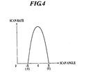
- FIG. 4 shows a relation between scan angle and scan rate of the scan mirror which vibrates in the sine vibration manner.
- the scan rate of the scan mirror reaches maximum at the center of an image where the scan angle (vibration amplitude) is zero and the scan rate of the scan mirror is zero at the edges of the image where the scan angles are maximum values of X and -X in horizontal direction (or, maximum values of Y, -Y in vertical direction). Therefore, scan width per time unit is not constant, and the scan width becomes smaller as approaching the edges of the image. Because the speed of the scan mirror is not constant, problems such that the image to be projected on the screen is distorted and that the brightness of the image is uneven occur.
- JP2004-279544 there is suggested an image display apparatus which corrects the equally spaced characteristic of line images in the scanning direction which occurs because of the deflection unit and the scan lens system, that is, an image display apparatus which carries out correction for spaces between each line images on a screen by changing the time interval of pixel clock for each pixel line unit.
- the pixel clock having a time interval which is longer than the regular clock is mixed in the pixel clock corresponding to the periphery blocks among the blocks in which the scanning area is divided. Thereby, the equally spaced characteristic is to be corrected.
- JP2004-279544 the technology for correcting the equally spaced characteristic disclosed in JP2004-279544 is carried out by controlling the time interval of the image clock, and there is a problem that the structure will be complicated because electrical control is needed.
- a main object of the present invention is to correct the distortion of the image due to the speed of the scan mirror not being constant in more simple structure in the projection image display apparatus which displays an image by scanning the light from the light source by the scan mirror.
- a projection image display apparatus to display an image by projecting a light from a light source to a screen comprising a scan mirror to scan the light from the light source by vibrating in a sine vibration manner at least in an one-dimensional direction and a correction lens which is disposed between the scan mirror and the screen and which corrects a deflection angle of the light scanned by the scan mirror at least in the one-dimensional direction, and the correction lens carries out a correction so that the larger a scan angle of the scan mirror is, the larger the deflection angle is to be by the correction.
- a projection image display apparatus to display an image by projection a light from a light source to a screen comprising a scan mirror to scan the light from the light source by vibrating in a sine vibration manner in a two-dimensional direction and a correction lens which is disposed between the scan mirror and the screen and which corrects a deflection angle of the light scanned by the scan mirror in the two-dimensional direction, and the correction lens includes a toric lens and carries out a correction so that the larger a scan angle of the scan mirror is, the larger the deflection angle is to be by the correction.
- FIG. 1 is a block diagram showing a main structure of a laser projector of the embodiment.
- FIG. 2 is a schematic view showing a main structure of a scan mirror.
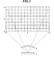
- FIG. 3 is a diagram for explaining an image which is to be displayed by the laser projector of the embodiment.
- the scope of the invention is not limited to the examples shown in the drawings.
- a laser projector (projection image display apparatus) 100 of the embodiment comprises light sources 1 which emit laser beams (lights), a mirror unit 2 to multiplex the laser beams emitted from the light sources 1, an image memory 3 to store image data of an image to be displayed on a screen S, a light source drive unit 4 to drive the light sources 1 based on the image data, a drive signal generation unit 5 to generate a sine wave alternating current signal of a predetermined frequency, a mirror drive unit 6 to drive the scan mirror 7 based on the sine wave alternating current signal which is generation in the drive signal generation unit 5, the scan mirror 7 which is driven by the mirror drive unit 6 to scan the laser beam emitted from the light sources 1 in two-dimensional direction, a correction lens 8 which is disposed between the scan mirror 7 and the screen S, a control unit 9 to integrally control the operation of the laser projector 100 and the like.
- the light sources 1 are the semiconductor lasers (LD: Laser Diode), and the light sources 1 modulate the image data from the image memory 3 and emit the laser beams of each color of red (R), green (G) and blue (B), respectively, by the drive of the light source drive unit 4.
- LD Laser Diode
- the light sources 1 modulate the image data from the image memory 3 and emit the laser beams of each color of red (R), green (G) and blue (B), respectively, by the drive of the light source drive unit 4.
- the mirror unit 2 is the dichroic mirror which transmits the light having a specific wave length and which reflects the light having wave length other than the specific wave length or the like, and the mirror unit 2 multiplexes the laser beams of each color emitted from a plurality of light sources 1 to a laser beam having light axis of single axis.
- the image memory 3 stores image data of an image to be displayed on the screen S.
- the supply source of image data is not limited to this, and image data stored in various types of storage devices such as a PC (Personal Computer) connected to a case, a video camera or the like may be used.
- the light source drive unit 4 drives the light sources 1 to adjust the laser beams for each pixel based on image data read from the image memory 3.
- the drive signal generation unit 5 generates the sine wave alternating current signal of innate resonance frequency of the scan mirror 7 in response to the control by the control unit 9.
- the mirror drive unit 6 is connected to the electrodes (after-mentioned) 76 of the scan mirror 7 and vibrates the scan mirror 7 in the sine vibration manner by supplying the sine wave alternating current signal generated in the drive signal generation unit 5 to the electrodes 76.
- the scan mirror 7 reflects the laser beam from the light sources 1 in two-dimensional direction to project the image on the screen S.
- an electromagnetic-driven MEMS mirror which applies the MEMS (Micro Electro Mechanical System) technology is used, for example, as the scan mirror 7 that carries out the two-dimensional scanning.
- the MEMS mirror is a micro device which is manufactured by accumulating mechanical mechanism and electric circuit on a silicon wafer by using the micro machining technology, and the entire apparatus can be made smaller by using the MEMS mirror.
- the scan mirror 7 comprises a mirror substrate 71 to reflect the laser beam, an inner frame 72 formed so as to enclose the mirror substrate 71 and an outer frame 73 formed so as to enclose the inner frame 72.
- the mirror substrate 71 is supported at inner side of the inner frame 72 by the inner hinges 74 and can swing about the axis of the inner hinges 74.
- the inner frame 72 is supported at inner side of the outer frame 73 by the outer hinges 75 in a direction orthogonal to the inner hinges 74 and can swing about the axis of the outer hinges 75.
- a mirror M is provided at approximately center of the surface of the mirror substrate 71, and a plan coil 71a is formed at the periphery of the mirror M so as to enclose the mirror M. Further, a plan coil 72a is formed at the periphery of the surface of the inner frame 72, and both ends of each of the coils 71a, 72a are electrically connected to the electrodes 76. Moreover, a pair of permanent magnets 77 and a pair of permanent magnets 78 are disposed at sides of the outer frame 73 so that the north pole of the magnet and the south pole of the magnet face each other in each pair.
- the Lorentz force is generated by the interaction with the magnetic field which is generated by the permanent magnets 77 and the mirror substrate 71 inclines to the position where the mirror substrate 71 is balanced with the resilience of the inner hinges 74, the inner hinges 74 acting as an axis. Further, when electric current is applied to the coil 72a, the Lorentz force is generated by the interaction with the magnetic field which is generated by the permanent magnets 78 and the inner frame 72 inclines to the position where the inner frame 72 is balances with the resilience of the outer hinges 75, the outer hinges 75 acting as an axis.
- the scan mirror 7 vibrates in the resonant vibration manner in two directions (horizontal direction and vertical direction) orthogonal to the axis of the inner hinges 74 and the outer hinges 75.
- the scan mirror 7 moves sinusoidally, and the scan width per unit time will be broader as approaching the center portion of the image where the scan angle is smaller and will be narrower as approaching the edges of the image where the scan angles are larger.
- the correction lens 8 is disposed between the scan mirror 7 and the screen S, and corrects the distortion of the image and the bias of brightness that occur due to speed change in the above described scan mirror 7 by correcting the deflection angle of the light scanned by the scan mirror 7 in two-dimensional direction.
- the toric lens is applied, for example.
- the light which entered the toric lens proceeds by being refracted in a direction so as to diffuse with respect to the two-dimensional direction.
- a concave cylindrical lens is used, for example, as the correction lens 8 to correct the deflection angle of the light only in one-dimensional direction.
- the light which entered the cylindrical lens proceeds straight without being refracted with respect to the one-dimensional direction and will proceed by being refracted in a direction so as to diffuse with respect to the one-dimensional direction.
- the laser projector 100 comprises the scan mirror 7 so scan the light from the light sources 1 by vibrating in the sine vibration manner in the two-dimensional direction and the correction lens 8 which is disposed between the scan mirror 7 and the screen S and which corrects the deflection angle of the light scanned by the scan mirror 7 in the two-dimensional direction, and the toric lens is included in the correction lens 8 and the larger the scan angle of the scan mirror 7 is, the larger the deflection angle is to be by the correction.
- the correction lens 8 which corrects the deflection angle of the light between the scan mirror 7 and the screen S, distortion of the image and unevenness of brightness which occur due to the scan mirror 7 vibrates sinusoidally are to be corrected. Therefore, in the projection image display apparatus in which an image is displayed by scanning the light from the light sources 1 by the scan mirror 7, distortion of the image due to the speed of the scan mirror 7 being not constant can be corrected in more simple structure.
- a detection unit to detect the displacement of rotation angle of the scan mirror a detection unit to detect the radiation position of the laser beam on the screen S or the like may be provided. Highly accurate angle control can be carried out by feeding back the detection signal from such detection unit to the drive unit of the scan mirror.
- types of the correction lens 8 is not limited to the examples shown in the above embodiment, and any lens can be used as long as the lens can make the light refract in the direction so as to broaden the light with respect to the scan mirror 7 in which the sine vibration is carried out. Further, number of the correction lens 8 is also not limited to one, and a plurality of lenses can be combined to be used.
- a projection image display apparatus to display an image by projecting a light from a light source to a screen comprising a scan mirror to scan the light from the light source by vibrating in a sine vibration manner at least in an one-dimensional direction and a correction lens which is disposed between the scan mirror and the screen and which corrects a deflection angle of the light scanned by the scan mirror at least in the one-dimensional direction, and the correction lens carries out a correction so that the larger a scan angle of the scan mirror is, the larger the deflection angle is to be by the correction.
- the correction lens includes a concave cylindrical lens.
- the scan mirror is a scan mirror which vibrates in the sine vibration manner in a two-dimensional direction and the correction lens includes a toric lens.
- a projection image display apparatus to display an image by projection a light from a light source to a screen comprising a scan mirror to scan the light from the light source by vibrating in a sine vibration manner in a two-dimensional direction and a correction lens which is disposed between the scan mirror and the screen and which corrects a deflection angle of the light scanned by the scan mirror in the two-dimensional direction, and the correction lens includes a toric lens and carries out a correction so that the larger a scan angle of the scan mirror is, the larger the deflection angle is to be by the correction.
- the projection image display apparatus comprises the scan mirror to scan the light from the light sources by vibrating in the sine vibration manner in at least one-dimensional direction and the correction lens which is disposed between the scan mirror and the screen and which corrects the deflection angle of the light scanned by the scan mirror in at least one-dimensional direction, and the correction lens carries out the correction so that the larger the scan angle of the scan mirror is, the larger the deflection angle is to be by the correction.
Abstract
Description
- The present invention relates to a projection image display apparatus using a scan mirror which vibrates in a sine vibration manner.
- Conventionally, there is known a projection image display apparatus using a resonant scan mirror as a projection image display apparatus such as a projector or the like. When the scan mirror is made to vibrate by a sine wave alternating current, the scan rate of the mirror is sinusoidally changed with respect to time.
-
FIG. 4 shows a relation between scan angle and scan rate of the scan mirror which vibrates in the sine vibration manner. As shown inFIG. 4 , the scan rate of the scan mirror reaches maximum at the center of an image where the scan angle (vibration amplitude) is zero and the scan rate of the scan mirror is zero at the edges of the image where the scan angles are maximum values of X and -X in horizontal direction (or, maximum values of Y, -Y in vertical direction). Therefore, scan width per time unit is not constant, and the scan width becomes smaller as approaching the edges of the image. Because the speed of the scan mirror is not constant, problems such that the image to be projected on the screen is distorted and that the brightness of the image is uneven occur. - In view of the above problems, in
JP2004-279544 - However, the technology for correcting the equally spaced characteristic disclosed in
JP2004-279544 - It is, therefore, a main object of the present invention is to correct the distortion of the image due to the speed of the scan mirror not being constant in more simple structure in the projection image display apparatus which displays an image by scanning the light from the light source by the scan mirror.
- According to a first aspect of the present invention, there is provided a projection image display apparatus to display an image by projecting a light from a light source to a screen comprising a scan mirror to scan the light from the light source by vibrating in a sine vibration manner at least in an one-dimensional direction and a correction lens which is disposed between the scan mirror and the screen and which corrects a deflection angle of the light scanned by the scan mirror at least in the one-dimensional direction, and the correction lens carries out a correction so that the larger a scan angle of the scan mirror is, the larger the deflection angle is to be by the correction.
- According to a second aspect of the present invention, there is provided a projection image display apparatus to display an image by projection a light from a light source to a screen comprising a scan mirror to scan the light from the light source by vibrating in a sine vibration manner in a two-dimensional direction and a correction lens which is disposed between the scan mirror and the screen and which corrects a deflection angle of the light scanned by the scan mirror in the two-dimensional direction, and the correction lens includes a toric lens and carries out a correction so that the larger a scan angle of the scan mirror is, the larger the deflection angle is to be by the correction.
- The above and other objects, advantages and features of the present invention will become more fully understood from the detailed description given hereinbelow and the appended drawings which are given by way of illustration only, and thus are not intended as a definition of the limits of the present invention, and wherein:
-
FIG. 1 is a block diagram showing a main structure of a laser projector of the embodiment; -
FIG. 2 is a schematic view showing a main structure of a scan mirror; -
FIG. 3 is a diagram for explaining an image which is to be displayed by the laser projector of the embodiment; -
FIG. 4 is a diagram showing a relation between scan rate and scan angle of the scan mirror which vibrates in a sine vibration manner; and -
FIG. 5 is a diagram for explaining an image which is to be displayed by a conventional projection image display apparatus. - Hereinafter, the embodiment of the present invention will be described with reference to the drawings.
- In the embodiment, a description will be given by exemplifying a laser projector using a laser beam (light) as a projection image display apparatus, for example.
-
FIG. 1 is a block diagram showing a main structure of a laser projector of the embodiment.FIG. 2 is a schematic view showing a main structure of a scan mirror.FIG. 3 is a diagram for explaining an image which is to be displayed by the laser projector of the embodiment. Here, the scope of the invention is not limited to the examples shown in the drawings. - As shown in
FIG. 1 , a laser projector (projection image display apparatus) 100 of the embodiment compriseslight sources 1 which emit laser beams (lights), amirror unit 2 to multiplex the laser beams emitted from thelight sources 1, animage memory 3 to store image data of an image to be displayed on a screen S, a light source drive unit 4 to drive thelight sources 1 based on the image data, a drivesignal generation unit 5 to generate a sine wave alternating current signal of a predetermined frequency, amirror drive unit 6 to drive thescan mirror 7 based on the sine wave alternating current signal which is generation in the drivesignal generation unit 5, thescan mirror 7 which is driven by themirror drive unit 6 to scan the laser beam emitted from thelight sources 1 in two-dimensional direction, acorrection lens 8 which is disposed between thescan mirror 7 and the screen S, acontrol unit 9 to integrally control the operation of the laser projector 100 and the like. - For example, the
light sources 1 are the semiconductor lasers (LD: Laser Diode), and thelight sources 1 modulate the image data from theimage memory 3 and emit the laser beams of each color of red (R), green (G) and blue (B), respectively, by the drive of the light source drive unit 4. - For example, the
mirror unit 2 is the dichroic mirror which transmits the light having a specific wave length and which reflects the light having wave length other than the specific wave length or the like, and themirror unit 2 multiplexes the laser beams of each color emitted from a plurality oflight sources 1 to a laser beam having light axis of single axis. - The
image memory 3 stores image data of an image to be displayed on the screen S. Here, the supply source of image data is not limited to this, and image data stored in various types of storage devices such as a PC (Personal Computer) connected to a case, a video camera or the like may be used. - The light source drive unit 4 drives the
light sources 1 to adjust the laser beams for each pixel based on image data read from theimage memory 3. - The drive
signal generation unit 5 generates the sine wave alternating current signal of innate resonance frequency of thescan mirror 7 in response to the control by thecontrol unit 9. - The
mirror drive unit 6 is connected to the electrodes (after-mentioned) 76 of thescan mirror 7 and vibrates thescan mirror 7 in the sine vibration manner by supplying the sine wave alternating current signal generated in the drivesignal generation unit 5 to theelectrodes 76. - The
scan mirror 7 reflects the laser beam from thelight sources 1 in two-dimensional direction to project the image on the screen S. In the embodiment, an electromagnetic-driven MEMS mirror which applies the MEMS (Micro Electro Mechanical System) technology is used, for example, as thescan mirror 7 that carries out the two-dimensional scanning. The MEMS mirror is a micro device which is manufactured by accumulating mechanical mechanism and electric circuit on a silicon wafer by using the micro machining technology, and the entire apparatus can be made smaller by using the MEMS mirror. - As shown in
FIG. 2 , thescan mirror 7 comprises amirror substrate 71 to reflect the laser beam, aninner frame 72 formed so as to enclose themirror substrate 71 and anouter frame 73 formed so as to enclose theinner frame 72. Themirror substrate 71 is supported at inner side of theinner frame 72 by theinner hinges 74 and can swing about the axis of theinner hinges 74. Further, theinner frame 72 is supported at inner side of theouter frame 73 by theouter hinges 75 in a direction orthogonal to theinner hinges 74 and can swing about the axis of theouter hinges 75. - A mirror M is provided at approximately center of the surface of the
mirror substrate 71, and aplan coil 71a is formed at the periphery of the mirror M so as to enclose the mirror M. Further, aplan coil 72a is formed at the periphery of the surface of theinner frame 72, and both ends of each of thecoils electrodes 76. Moreover, a pair ofpermanent magnets 77 and a pair ofpermanent magnets 78 are disposed at sides of theouter frame 73 so that the north pole of the magnet and the south pole of the magnet face each other in each pair. - When electric current is applied to the
coil 71a in the above scan mirror M7, the Lorentz force is generated by the interaction with the magnetic field which is generated by thepermanent magnets 77 and themirror substrate 71 inclines to the position where themirror substrate 71 is balanced with the resilience of theinner hinges 74, theinner hinges 74 acting as an axis. Further, when electric current is applied to thecoil 72a, the Lorentz force is generated by the interaction with the magnetic field which is generated by thepermanent magnets 78 and theinner frame 72 inclines to the position where theinner frame 72 is balances with the resilience of theouter hinges 75, theouter hinges 75 acting as an axis. - When the sine wave alternating current of innate resonance frequency of the
scan mirror 7 is applied to thecoils scan mirror 7, thescan mirror 7 vibrates in the resonant vibration manner in two directions (horizontal direction and vertical direction) orthogonal to the axis of theinner hinges 74 and theouter hinges 75. During the resonant vibration, thescan mirror 7 moves sinusoidally, and the scan width per unit time will be broader as approaching the center portion of the image where the scan angle is smaller and will be narrower as approaching the edges of the image where the scan angles are larger. - The
correction lens 8 is disposed between thescan mirror 7 and the screen S, and corrects the distortion of the image and the bias of brightness that occur due to speed change in the above describedscan mirror 7 by correcting the deflection angle of the light scanned by thescan mirror 7 in two-dimensional direction. The larger the scan angle of thescan mirror 7 is, the larger the deflection angle is to be by the correction by thecorrection lens 8. That is, thecorrection lens 8 carries out the correction in a direction so as to broaden the light path of the light from thescan mirror 7 as the light approaches the edges of the image where the scan angles become larger. Therefore, as shown inFIG. 4 , the scan width per time unit will be constant in the entire screen and the laser beam from thescan mirror 7 can scan the screen S in a constant speed. - As for the
correction lens 8 having the above characteristic, the toric lens is applied, for example. The light which entered the toric lens proceeds by being refracted in a direction so as to diffuse with respect to the two-dimensional direction. Further, the arcsine lens having the arcsine (arc-sin) characteristic shown by 1=fsin-1θ (here, 1:scan distance, f:focus distance, θ:incidence angle) is preferable. - Moreover, when the
scan mirror 7 is vibrated in the sine vibration manner only in one-dimensional direction, a concave cylindrical lens is used, for example, as thecorrection lens 8 to correct the deflection angle of the light only in one-dimensional direction. The light which entered the cylindrical lens proceeds straight without being refracted with respect to the one-dimensional direction and will proceed by being refracted in a direction so as to diffuse with respect to the one-dimensional direction. - According to the above described laser projector (projection image display apparatus) 100 of the present embodiment, the laser projector 100 comprises the
scan mirror 7 so scan the light from thelight sources 1 by vibrating in the sine vibration manner in the two-dimensional direction and thecorrection lens 8 which is disposed between thescan mirror 7 and the screen S and which corrects the deflection angle of the light scanned by thescan mirror 7 in the two-dimensional direction, and the toric lens is included in thecorrection lens 8 and the larger the scan angle of thescan mirror 7 is, the larger the deflection angle is to be by the correction. - That is, by disposing the
correction lens 8 which corrects the deflection angle of the light between thescan mirror 7 and the screen S, distortion of the image and unevenness of brightness which occur due to thescan mirror 7 vibrates sinusoidally are to be corrected. Therefore, in the projection image display apparatus in which an image is displayed by scanning the light from thelight sources 1 by thescan mirror 7, distortion of the image due to the speed of thescan mirror 7 being not constant can be corrected in more simple structure. - Here, the present invention is not limited to the scope of the above embodiment, and various modifications and changes in design can be carried out within the scope of the present invention.
- For example, a detection unit to detect the displacement of rotation angle of the scan mirror, a detection unit to detect the radiation position of the laser beam on the screen S or the like may be provided. Highly accurate angle control can be carried out by feeding back the detection signal from such detection unit to the drive unit of the scan mirror.
- Moreover, types of the
correction lens 8 is not limited to the examples shown in the above embodiment, and any lens can be used as long as the lens can make the light refract in the direction so as to broaden the light with respect to thescan mirror 7 in which the sine vibration is carried out. Further, number of thecorrection lens 8 is also not limited to one, and a plurality of lenses can be combined to be used. - According to a first aspect of the preferred embodiment of the present invention, there is provided a projection image display apparatus to display an image by projecting a light from a light source to a screen comprising a scan mirror to scan the light from the light source by vibrating in a sine vibration manner at least in an one-dimensional direction and a correction lens which is disposed between the scan mirror and the screen and which corrects a deflection angle of the light scanned by the scan mirror at least in the one-dimensional direction, and the correction lens carries out a correction so that the larger a scan angle of the scan mirror is, the larger the deflection angle is to be by the correction.
- Preferably, the correction lens includes a concave cylindrical lens.
- Preferably, the scan mirror is a scan mirror which vibrates in the sine vibration manner in a two-dimensional direction and the correction lens includes a toric lens.
- According to a second aspect of the preferred embodiment of the present invention, there is provided a projection image display apparatus to display an image by projection a light from a light source to a screen comprising a scan mirror to scan the light from the light source by vibrating in a sine vibration manner in a two-dimensional direction and a correction lens which is disposed between the scan mirror and the screen and which corrects a deflection angle of the light scanned by the scan mirror in the two-dimensional direction, and the correction lens includes a toric lens and carries out a correction so that the larger a scan angle of the scan mirror is, the larger the deflection angle is to be by the correction.
- According to the present invention, the projection image display apparatus comprises the scan mirror to scan the light from the light sources by vibrating in the sine vibration manner in at least one-dimensional direction and the correction lens which is disposed between the scan mirror and the screen and which corrects the deflection angle of the light scanned by the scan mirror in at least one-dimensional direction, and the correction lens carries out the correction so that the larger the scan angle of the scan mirror is, the larger the deflection angle is to be by the correction.
- That is, by disposing the correction lens which corrects the deflection angle of the light between the scan mirror and the screen, distortion of the image and unevenness of brightness which occur due to the scan mirror vibrates sinusoidally are to be corrected. Therefore, in the projection image display apparatus in which an image is displayed by scanning the light from the light sources by the scan mirror, distortion of the image due to the speed of the scan mirror being not constant can be corrected in more simple structure.
- The entire disclosure of Japanese Patent Application No.
2008-087635 filed on March 28, 2008 - Although various exemplary embodiments have been shown and described, the invention is not limited to the embodiments shown. Therefore, the scope of the invention is intended to be limited solely by the scope of the claims that follow.
Claims (4)
- A projection image display apparatus to display an image by projecting a light from a light source to a screen, comprising:a scan mirror to scan the light from the light source by vibrating in a sine vibration manner at least in an one-dimensional direction; anda correction lens which is disposed between the scan mirror and the screen and which corrects a deflection angle of the light scanned by the scan mirror at least in the one-dimensional direction, whereinthe correction lens carries out a correction so that the larger a scan angle of the scan mirror is, the larger the deflection angle is to be by the correction.
- The projection image display apparatus as claimed in claim 1, wherein the correction lens includes a concave cylindrical lens.
- The projection image display apparatus as claimed in claim 1, wherein the scan mirror is a scan mirror which vibrates in the sine vibration manner in a two-dimensional direction, and the correction lens includes a toric lens.
- A projection image display apparatus to display an image by projection a light from a light source to a screen, comprising:a scan mirror to scan the light from the light source by vibrating in a sine vibration manner in a two-dimensional direction; anda correction lens which is disposed between the scan mirror and the screen and which corrects a deflection angle of the light scanned by the scan mirror in the two-dimensional direction, whereinthe correction lens includes a toric lens and carries out a correction so that the larger a scan angle of the scan mirror is, the larger the deflection angle is to be by the correction.
Applications Claiming Priority (1)
| Application Number | Priority Date | Filing Date | Title |
|---|---|---|---|
| JP2008087635A JP2009244330A (en) | 2008-03-28 | 2008-03-28 | Projection type image display |
Publications (2)
| Publication Number | Publication Date |
|---|---|
| EP2105791A1 true EP2105791A1 (en) | 2009-09-30 |
| EP2105791B1 EP2105791B1 (en) | 2012-05-30 |
Family
ID=40729498
Family Applications (1)
| Application Number | Title | Priority Date | Filing Date |
|---|---|---|---|
| EP09004124A Expired - Fee Related EP2105791B1 (en) | 2008-03-28 | 2009-03-23 | Projection image display apparatus |
Country Status (4)
| Country | Link |
|---|---|
| US (1) | US7835053B2 (en) |
| EP (1) | EP2105791B1 (en) |
| JP (1) | JP2009244330A (en) |
| CN (1) | CN101546104B (en) |
Cited By (1)
| Publication number | Priority date | Publication date | Assignee | Title |
|---|---|---|---|---|
| EP2697686A2 (en) * | 2011-04-14 | 2014-02-19 | Microvision, Inc. | Free form optical redirection apparatus |
Families Citing this family (16)
| Publication number | Priority date | Publication date | Assignee | Title |
|---|---|---|---|---|
| TW201024901A (en) * | 2008-12-16 | 2010-07-01 | Ind Tech Res Inst | Optical scanner |
| JP4905611B2 (en) | 2009-11-16 | 2012-03-28 | 日本電気株式会社 | Optical scanning device |
| CN102253487B (en) * | 2010-05-21 | 2013-05-22 | 常晓旺 | Laser scanning image projector |
| CN102375239A (en) * | 2010-08-20 | 2012-03-14 | 富港电子(东莞)有限公司 | Projection system and method |
| JP5803184B2 (en) | 2010-11-19 | 2015-11-04 | 株式会社リコー | Image projection apparatus and memory access method |
| TWI408413B (en) * | 2011-02-25 | 2013-09-11 | Ind Tech Res Inst | Two dimension scanning and reflecting device |
| JP6135389B2 (en) * | 2012-09-19 | 2017-05-31 | 船井電機株式会社 | Image display device and optical component |
| JP6024332B2 (en) * | 2012-09-19 | 2016-11-16 | 船井電機株式会社 | Image display device |
| CN103852962B (en) * | 2012-12-04 | 2016-08-10 | 光宝科技股份有限公司 | Scanning projection device and scan control method thereof |
| US9723280B2 (en) * | 2013-01-22 | 2017-08-01 | Sony Corporation | Projection type image display device, image processing device and image processing method, and computer program |
| CN104808327B (en) * | 2015-05-15 | 2017-10-27 | 华东理工大学 | A kind of microscope for cell operation |
| CN104932098B (en) | 2015-07-17 | 2017-04-05 | 京东方科技集团股份有限公司 | Micro mirror array and the backlight module and display device using which |
| CN106997152B (en) * | 2016-01-26 | 2019-11-26 | 上海微电子装备(集团)股份有限公司 | Scanning reflection mirror monitors system and method, focusing and leveling system |
| US11126069B2 (en) * | 2018-06-27 | 2021-09-21 | Coretronic Corporation | Projector and optical module including extending wire |
| JP7195078B2 (en) * | 2018-07-20 | 2022-12-23 | スタンレー電気株式会社 | Light irradiation device |
| CN110460828B (en) * | 2019-08-22 | 2021-03-19 | 淮南师范学院 | Micro-electro-mechanical scanning mirror projection system and method |
Citations (8)
| Publication number | Priority date | Publication date | Assignee | Title |
|---|---|---|---|---|
| JP2001281583A (en) * | 2000-03-29 | 2001-10-10 | Olympus Optical Co Ltd | Scanning optical system |
| EP1450558A1 (en) * | 2003-02-18 | 2004-08-25 | Canon Kabushiki Kaisha | Scan type display |
| JP2004279544A (en) | 2003-03-13 | 2004-10-07 | Ricoh Co Ltd | Line image scanning type picture display device |
| EP1566972A2 (en) * | 2004-02-19 | 2005-08-24 | Canon Kabushiki Kaisha | Two dimensional scanning apparatus and scanning type image displaying apparatus using the same |
| DE102004063554A1 (en) * | 2004-12-30 | 2006-07-13 | Siemens Ag | Compensation of the varying line spacing in projection systems with oscillating mirrors |
| US20070176084A1 (en) * | 2006-01-27 | 2007-08-02 | E-Pin Optical Industry Co., Ltd. | In-line laser scanning unit with multiple light beams |
| US20080143979A1 (en) * | 2006-12-15 | 2008-06-19 | Konica Minolta Opto, Inc. | Laser projection device |
| WO2009003510A1 (en) * | 2007-06-29 | 2009-01-08 | Osram Gesellschaft mit beschränkter Haftung | Lens for laser projection |
Family Cites Families (6)
| Publication number | Priority date | Publication date | Assignee | Title |
|---|---|---|---|---|
| KR100215298B1 (en) * | 1997-07-03 | 1999-08-16 | 윤종용 | A compacted beam pass expander and the method for expanding beam pass |
| JP4006313B2 (en) * | 2002-10-17 | 2007-11-14 | キヤノン株式会社 | Scanning display optical system and scanning display device |
| JP2004279644A (en) | 2003-03-14 | 2004-10-07 | Pioneer Electronic Corp | Image signal processor |
| CN1719303A (en) * | 2004-07-07 | 2006-01-11 | 中国科学院光电技术研究所 | A kind of with cylindrical mirror correction tilting mirror tower difference method and laser large screen display system thereof |
| JP4522253B2 (en) * | 2004-12-24 | 2010-08-11 | キヤノン株式会社 | Optical scanning device and image display device using the same |
| CN1979248A (en) * | 2005-12-08 | 2007-06-13 | 刘晓松 | Multi-point scanning projector |
-
2008
- 2008-03-28 JP JP2008087635A patent/JP2009244330A/en active Pending
-
2009
- 2009-03-18 CN CN2009101282381A patent/CN101546104B/en not_active Expired - Fee Related
- 2009-03-20 US US12/408,305 patent/US7835053B2/en not_active Expired - Fee Related
- 2009-03-23 EP EP09004124A patent/EP2105791B1/en not_active Expired - Fee Related
Patent Citations (8)
| Publication number | Priority date | Publication date | Assignee | Title |
|---|---|---|---|---|
| JP2001281583A (en) * | 2000-03-29 | 2001-10-10 | Olympus Optical Co Ltd | Scanning optical system |
| EP1450558A1 (en) * | 2003-02-18 | 2004-08-25 | Canon Kabushiki Kaisha | Scan type display |
| JP2004279544A (en) | 2003-03-13 | 2004-10-07 | Ricoh Co Ltd | Line image scanning type picture display device |
| EP1566972A2 (en) * | 2004-02-19 | 2005-08-24 | Canon Kabushiki Kaisha | Two dimensional scanning apparatus and scanning type image displaying apparatus using the same |
| DE102004063554A1 (en) * | 2004-12-30 | 2006-07-13 | Siemens Ag | Compensation of the varying line spacing in projection systems with oscillating mirrors |
| US20070176084A1 (en) * | 2006-01-27 | 2007-08-02 | E-Pin Optical Industry Co., Ltd. | In-line laser scanning unit with multiple light beams |
| US20080143979A1 (en) * | 2006-12-15 | 2008-06-19 | Konica Minolta Opto, Inc. | Laser projection device |
| WO2009003510A1 (en) * | 2007-06-29 | 2009-01-08 | Osram Gesellschaft mit beschränkter Haftung | Lens for laser projection |
Cited By (4)
| Publication number | Priority date | Publication date | Assignee | Title |
|---|---|---|---|---|
| EP2697686A2 (en) * | 2011-04-14 | 2014-02-19 | Microvision, Inc. | Free form optical redirection apparatus |
| EP2697686A4 (en) * | 2011-04-14 | 2014-03-26 | Microvision Inc | Free form optical redirection apparatus |
| US8992028B2 (en) | 2011-04-14 | 2015-03-31 | Microvision, Inc. | Free form optical redirection apparatus and devices using same |
| US9217913B2 (en) | 2011-04-14 | 2015-12-22 | Microvision, Inc. | Free form optical redirection apparatus and devices using same |
Also Published As
| Publication number | Publication date |
|---|---|
| US7835053B2 (en) | 2010-11-16 |
| CN101546104B (en) | 2012-09-26 |
| JP2009244330A (en) | 2009-10-22 |
| CN101546104A (en) | 2009-09-30 |
| EP2105791B1 (en) | 2012-05-30 |
| US20090244673A1 (en) | 2009-10-01 |
Similar Documents
| Publication | Publication Date | Title |
|---|---|---|
| EP2105791B1 (en) | Projection image display apparatus | |
| US7978387B2 (en) | Laser projector | |
| US8459799B2 (en) | Optical scanning projector with raster scanning unit and vector scanning unit | |
| US8717655B2 (en) | Image forming apparatus | |
| US20110279879A1 (en) | Image forming apparatus | |
| US8368006B2 (en) | Driving a laser scanning section using a basic period of a pulse signal based on a period of a resonance frequency and accumulated period errors to produce a correction period quantity | |
| US20090195644A1 (en) | Image forming apparatus | |
| US8643926B2 (en) | Image forming apparatus | |
| US8416481B2 (en) | Laser projector | |
| JP6515631B2 (en) | Image display device and adjustment device | |
| CN111190280B (en) | Optical path shifting device, image display apparatus, and control method of optical path shifting device | |
| EP3037866A1 (en) | Optical device, image display device, and method of manufacturing optical device | |
| JP5234514B2 (en) | Image forming apparatus | |
| JP2019053128A (en) | Display device and method for controlling display device | |
| JP2010230730A (en) | Image forming apparatus | |
| JP5402589B2 (en) | Optical scanning device | |
| JP2012181479A (en) | Image forming device | |
| JP5402588B2 (en) | Optical scanning device | |
| JP2011107237A (en) | Image forming apparatus | |
| JP2012145754A (en) | Image display device | |
| JP2011102845A (en) | Image forming apparatus | |
| JP2010204217A (en) | Image forming apparatus | |
| JP2011170140A (en) | Image forming apparatus | |
| JP2012013746A (en) | Image forming device | |
| JP2012145674A (en) | Image formation device |
Legal Events
| Date | Code | Title | Description |
|---|---|---|---|
| PUAI | Public reference made under article 153(3) epc to a published international application that has entered the european phase |
Free format text: ORIGINAL CODE: 0009012 |
|
| AK | Designated contracting states |
Kind code of ref document: A1 Designated state(s): AT BE BG CH CY CZ DE DK EE ES FI FR GB GR HR HU IE IS IT LI LT LU LV MC MK MT NL NO PL PT RO SE SI SK TR |
|
| AX | Request for extension of the european patent |
Extension state: AL BA RS |
|
| 17P | Request for examination filed |
Effective date: 20091209 |
|
| AKX | Designation fees paid |
Designated state(s): DE FR GB |
|
| 17Q | First examination report despatched |
Effective date: 20110401 |
|
| GRAP | Despatch of communication of intention to grant a patent |
Free format text: ORIGINAL CODE: EPIDOSNIGR1 |
|
| GRAS | Grant fee paid |
Free format text: ORIGINAL CODE: EPIDOSNIGR3 |
|
| GRAA | (expected) grant |
Free format text: ORIGINAL CODE: 0009210 |
|
| AK | Designated contracting states |
Kind code of ref document: B1 Designated state(s): DE FR GB |
|
| REG | Reference to a national code |
Ref country code: GB Ref legal event code: FG4D |
|
| REG | Reference to a national code |
Ref country code: DE Ref legal event code: R096 Ref document number: 602009007254 Country of ref document: DE Effective date: 20120802 |
|
| PLBE | No opposition filed within time limit |
Free format text: ORIGINAL CODE: 0009261 |
|
| STAA | Information on the status of an ep patent application or granted ep patent |
Free format text: STATUS: NO OPPOSITION FILED WITHIN TIME LIMIT |
|
| 26N | No opposition filed |
Effective date: 20130301 |
|
| REG | Reference to a national code |
Ref country code: DE Ref legal event code: R097 Ref document number: 602009007254 Country of ref document: DE Effective date: 20130301 |
|
| REG | Reference to a national code |
Ref country code: FR Ref legal event code: PLFP Year of fee payment: 8 |
|
| PGFP | Annual fee paid to national office [announced via postgrant information from national office to epo] |
Ref country code: FR Payment date: 20160208 Year of fee payment: 8 Ref country code: GB Payment date: 20160323 Year of fee payment: 8 |
|
| REG | Reference to a national code |
Ref country code: DE Ref legal event code: R084 Ref document number: 602009007254 Country of ref document: DE |
|
| GBPC | Gb: european patent ceased through non-payment of renewal fee |
Effective date: 20170323 |
|
| REG | Reference to a national code |
Ref country code: FR Ref legal event code: ST Effective date: 20171130 |
|
| PG25 | Lapsed in a contracting state [announced via postgrant information from national office to epo] |
Ref country code: FR Free format text: LAPSE BECAUSE OF NON-PAYMENT OF DUE FEES Effective date: 20170331 |
|
| PG25 | Lapsed in a contracting state [announced via postgrant information from national office to epo] |
Ref country code: GB Free format text: LAPSE BECAUSE OF NON-PAYMENT OF DUE FEES Effective date: 20170323 |
|
| PGFP | Annual fee paid to national office [announced via postgrant information from national office to epo] |
Ref country code: DE Payment date: 20220203 Year of fee payment: 14 |
|
| REG | Reference to a national code |
Ref country code: DE Ref legal event code: R119 Ref document number: 602009007254 Country of ref document: DE |
|
| PG25 | Lapsed in a contracting state [announced via postgrant information from national office to epo] |
Ref country code: DE Free format text: LAPSE BECAUSE OF NON-PAYMENT OF DUE FEES Effective date: 20231003 |