EP2105843A1 - Active medical device comprising perfected means for distinguishing between tachycardia with ventricular causes and tachycardia with supraventricular causes - Google Patents
Active medical device comprising perfected means for distinguishing between tachycardia with ventricular causes and tachycardia with supraventricular causes Download PDFInfo
- Publication number
- EP2105843A1 EP2105843A1 EP09290016A EP09290016A EP2105843A1 EP 2105843 A1 EP2105843 A1 EP 2105843A1 EP 09290016 A EP09290016 A EP 09290016A EP 09290016 A EP09290016 A EP 09290016A EP 2105843 A1 EP2105843 A1 EP 2105843A1
- Authority
- EP
- European Patent Office
- Prior art keywords
- tachycardia
- characteristic
- beats
- ventricular
- analysis
- Prior art date
- Legal status (The legal status is an assumption and is not a legal conclusion. Google has not performed a legal analysis and makes no representation as to the accuracy of the status listed.)
- Granted
Links
Images


Classifications
-
- A—HUMAN NECESSITIES
- A61—MEDICAL OR VETERINARY SCIENCE; HYGIENE
- A61B—DIAGNOSIS; SURGERY; IDENTIFICATION
- A61B5/00—Measuring for diagnostic purposes; Identification of persons
- A61B5/72—Signal processing specially adapted for physiological signals or for diagnostic purposes
- A61B5/7235—Details of waveform analysis
- A61B5/7264—Classification of physiological signals or data, e.g. using neural networks, statistical classifiers, expert systems or fuzzy systems
-
- A—HUMAN NECESSITIES
- A61—MEDICAL OR VETERINARY SCIENCE; HYGIENE
- A61B—DIAGNOSIS; SURGERY; IDENTIFICATION
- A61B5/00—Measuring for diagnostic purposes; Identification of persons
- A61B5/24—Detecting, measuring or recording bioelectric or biomagnetic signals of the body or parts thereof
- A61B5/316—Modalities, i.e. specific diagnostic methods
- A61B5/318—Heart-related electrical modalities, e.g. electrocardiography [ECG]
- A61B5/346—Analysis of electrocardiograms
- A61B5/349—Detecting specific parameters of the electrocardiograph cycle
- A61B5/363—Detecting tachycardia or bradycardia
-
- A—HUMAN NECESSITIES
- A61—MEDICAL OR VETERINARY SCIENCE; HYGIENE
- A61B—DIAGNOSIS; SURGERY; IDENTIFICATION
- A61B5/00—Measuring for diagnostic purposes; Identification of persons
- A61B5/24—Detecting, measuring or recording bioelectric or biomagnetic signals of the body or parts thereof
- A61B5/316—Modalities, i.e. specific diagnostic methods
- A61B5/318—Heart-related electrical modalities, e.g. electrocardiography [ECG]
- A61B5/339—Displays specially adapted therefor
- A61B5/341—Vectorcardiography [VCG]
-
- A—HUMAN NECESSITIES
- A61—MEDICAL OR VETERINARY SCIENCE; HYGIENE
- A61B—DIAGNOSIS; SURGERY; IDENTIFICATION
- A61B5/00—Measuring for diagnostic purposes; Identification of persons
- A61B5/72—Signal processing specially adapted for physiological signals or for diagnostic purposes
- A61B5/7235—Details of waveform analysis
- A61B5/7264—Classification of physiological signals or data, e.g. using neural networks, statistical classifiers, expert systems or fuzzy systems
- A61B5/7267—Classification of physiological signals or data, e.g. using neural networks, statistical classifiers, expert systems or fuzzy systems involving training the classification device
-
- A—HUMAN NECESSITIES
- A61—MEDICAL OR VETERINARY SCIENCE; HYGIENE
- A61N—ELECTROTHERAPY; MAGNETOTHERAPY; RADIATION THERAPY; ULTRASOUND THERAPY
- A61N1/00—Electrotherapy; Circuits therefor
- A61N1/18—Applying electric currents by contact electrodes
- A61N1/32—Applying electric currents by contact electrodes alternating or intermittent currents
- A61N1/36—Applying electric currents by contact electrodes alternating or intermittent currents for stimulation
- A61N1/362—Heart stimulators
- A61N1/3621—Heart stimulators for treating or preventing abnormally high heart rate
- A61N1/3622—Heart stimulators for treating or preventing abnormally high heart rate comprising two or more electrodes co-operating with different heart regions
-
- G—PHYSICS
- G06—COMPUTING; CALCULATING OR COUNTING
- G06F—ELECTRIC DIGITAL DATA PROCESSING
- G06F2218/00—Aspects of pattern recognition specially adapted for signal processing
- G06F2218/12—Classification; Matching
- G06F2218/16—Classification; Matching by matching signal segments
- G06F2218/18—Classification; Matching by matching signal segments by plotting the signal segments against each other, e.g. analysing scattergrams
-
- G—PHYSICS
- G16—INFORMATION AND COMMUNICATION TECHNOLOGY [ICT] SPECIALLY ADAPTED FOR SPECIFIC APPLICATION FIELDS
- G16H—HEALTHCARE INFORMATICS, i.e. INFORMATION AND COMMUNICATION TECHNOLOGY [ICT] SPECIALLY ADAPTED FOR THE HANDLING OR PROCESSING OF MEDICAL OR HEALTHCARE DATA
- G16H50/00—ICT specially adapted for medical diagnosis, medical simulation or medical data mining; ICT specially adapted for detecting, monitoring or modelling epidemics or pandemics
- G16H50/20—ICT specially adapted for medical diagnosis, medical simulation or medical data mining; ICT specially adapted for detecting, monitoring or modelling epidemics or pandemics for computer-aided diagnosis, e.g. based on medical expert systems
Definitions
- the invention relates to a technique for analyzing ventricular tachyarrhythmias.
- the invention can be implemented not only within an implant, but also outside the patient's body, for example in an external programmer used by a practitioner to download and analyze the cardiac signals collected. and stored by the implant.
- the invention can also be implemented in a "home monitoring" monitor, which is a particular type of programmer whose operation is fully automated; such a monitor does not require the use of a practitioner, and allows in particular to remotely transmit to a remote site data collected by an implant, for analysis and monitoring of the patient.
- the invention can also be implemented at the data server of this site, from the data transmitted as is by the patient monitor.
- a tachyarrhythmia (abnormal rapid heartbeat) may be of sinus, atrial or ventricular origin.
- VT true ventricular tachycardia
- SVT supraventricular tachycardia
- the application of a shock of defibrillation in a conscious patient is extremely painful and distressing, the applied energies being indeed well beyond the threshold of pain.
- the application of a defibrillation shock is not devoid of side effects on the heart rate (risk of occurrence of secondary disorders), on the functional integrity of the myocardium, and generally on the physiological balance of the patient.
- tachycardia can include various forms of cardiac arrhythmias: when tachyarrhythmia is present, it may be due to ventricular fibrillation (VF), ventricular tachycardia (VT), sinus tachycardia (TS) or supraventricular tachycardia (TSV). TSV itself covers atrial tachycardia, atrial flutter and atrial fibrillation (AF). These disorders can also be superimposed and it is called "bitachycardia", especially in the presence of atrial fibrillation combined with ventricular tachycardia.
- VF ventricular fibrillation
- VT ventricular tachycardia
- TS sinus tachycardia
- TSV supraventricular tachycardia
- the difficulty lies in the fact that, in many pathological situations, certain events that are present are not visible because they are masked by other concomitant events.
- the large complexes of a fast TV often make it difficult to recognize the P waves, which does not always make it possible to differentiate them from those of a flutter associated with a functional branch block.
- the discrimination criteria employed by these devices include in particular the ventricular rate, the stability of the ventricular intervals (RR intervals), the analysis of the atrioventricular association (revealed by the stability of the PR interval) and the mode of start of tachycardias (presence of sudden acceleration and original cavity, ventricular or atrial).
- EP 0 626 182 A1 (ELA Medical), which describes an algorithm for the detection and classification of tachyarrhythmias called PARAD / PARAD + implemented in particular in the Defender and Ovatio models of ELA Medical.
- the EP 0 838 235 A1 , EP 0 813 888 A1 and EP 1 208 873 A1 (all in the name of ELA Medical) describe various improvements to this algorithm, allowing to further improve the discrimination between TV and TSV, in particular to avoid false positive diagnoses (indication of a TV when it was a question of 'a TSV) or negative (indication of a TSV while it was a TV).
- QRS morphological analysis
- VTC Electrogram Vector Timing and Correlation
- the algorithm creates a reference beat in sinus rhythm, by the steps of: (i) collecting a certain number of complexes of a unipolar VD signal (between the housing and an electrode on the probe), (ii ) align these complexes with each other by means of the corresponding bipolar VD signal (collected between two electrodes on the probe), (iii) average the complexes thus aligned, and finally (iv) extract from the average reference beat eight representative points (minimum , maximum, inflection points, etc.) to define a template or " template ".
- the VTC algorithm calculates the correlation coefficient between these eight model reference points and the eight similar points of the tachycardia beat collected on the (single) unipolar VD signal path. If for a given tachycardia the algorithm finds a sufficient number of uncorrelated beats, then this tachycardia is classified as being of ventricular origin - which may therefore warrant the application of a defibrillation shock. In the case of a dual chamber defibrillator, the VTC morphological analysis algorithm can be improved by taking into account additional, non-morphological criteria (V> A and stability).
- MD Morphology Discrimination
- US 7,149,569 B1 Pieretter Inc.
- a percent match between a model beat and each arrhythmia beat to be analyzed which percentage is a function of amplitude, polarity and order of peaks. If at least five beats out of eight have a match percentage lower than a threshold value, then the arrhythmia is characterized as a ventricular tachycardia (the threshold can be programmed with values between 30% and 95%).
- this algorithm must be programmed so that it also takes into account non-morphological criteria (acceleration, stability) in order to obtain satisfactory results.
- the WO 00/69517 A1 (Medtronic Inc.) describes a third method, called Wavelet Dynamic Discrimination, which compares the morphology of a basic rhythm and the morphology of tachycardia based on the difference between wavelet coefficients, this difference being expressed in terms of a percentage of correspondence. Beats for which this percentage is less than a nominal value of 70% are classified as being of ventricular origin, after which tachycardia is classified as being of ventricular origin if at least six out of eight beats meet this criterion. .
- the object of the invention is to overcome the aforementioned drawbacks, by proposing a new analysis technique to virtually eliminate any risk of false diagnosis of TV (false positive or false negative) when discrimination between TV and TSV, so to reduce the number of inappropriate shocks due to poor discrimination, and this in all clinical situations likely to be encountered, thus ensuring greater reliability of tachyarrhythmia analysis.
- the object of the invention is to improve the decision-making of implantable defibrillators in the discrimination between TV and
- the basic idea of the invention lies in the observation that relevant discrimination parameters between TV and SVV can be obtained by analyzing EGM signals originating from the same cavity (the ventricle) and collected concurrently on two distinct pathways, these signals being combined with each other in the form of two respective components applied to a two-dimensional analysis - thus disregarding the temporal dimension.
- the two different EGM channels are for example that of the unipolar signal (collected between the housing and one of the distal or proximal electrodes), and that of the bipolar signal (collected between the two distal and proximal electrodes).
- the invention proposes, as with existing methods, to discriminate TV / SVV from a measurement of the similarity of the signals recorded during the arrhythmia to those recorded in sinus rhythm.
- this discrimination TV / TSV is operated from the "cardiac loop” or "vectogram", which is the representation of one of these signals with respect to the other, in a space to two dimensions.
- This space is typically a space "unipolar path (ordinate) vs. bipolar path (abscissa)”.
- Each beat (or significant fraction of beat) is then represented by its vectogram in the plane thus defined.
- the beat is compared to a corresponding reference vectogram obtained in sinus rhythm.
- the algorithm estimates the greater or less similarity with this reference vectogram and discriminates accordingly the type of arrhythmia, TV (low similarity) or TSV (strong similarity).
- the invention proposes an active medical device of the type disclosed by the US 2005/0159781 A1 above, corresponding to the preamble of claim 1.
- the characterizing part of this claim 1 states the characteristic elements of the invention.
- each vectogram sinus rhythm and arrhythmia
- tangent vector and curvature at each point.
- Subclaims 14 to 29 are directed to a second embodiment of the invention, wherein the vectogram is characterized by projection into an orthonormal basis defined from sinus rhythm by principal component analysis.
- the invention can be implemented by appropriate programming of the control software of a known device, for example of the pacemaker or defibrillator type, comprising means for acquiring a signal provided. by endocavitary probes.
- the invention can in particular be applied to implantable devices such as the devices of the Ovatio range marketed by ELA Medical, Montrouge, France. These are programmable microprocessor devices to which it is possible to transmit by telemetry software that will be stored in memory and executed to implement the functions of the invention which will be described below.
- telemetry software that will be stored in memory and executed to implement the functions of the invention which will be described below.
- the adaptation of these devices to the implementation of the functions of the invention is within the abilities of those skilled in the art, and it will not be described in detail.
- the assay technique of the invention consists in discriminating between ventricular TV (or VT) tachycardias and supraventricular tachycardias TSV (or SVT) from the two-way EGM electrogram signals. distinct and analyzed in two dimensions.
- the Figure 1 illustrates, in the case of a patient presenting a sinus rhythm RS (or SR), the plot of the BipV and UnipV electrograms respectively observed on the ventricular bipolar pathway ( Fig. 1a ) and on the unipolar ventricular pathway ( Fig. 1b ).
- RS sinus rhythm
- the Figure 2 illustrates, in the same way, the corresponding signals BipV and UnipV observed in the case of a patient having a TSV.
- the next step is, once these signals are collected (in the time domain), to draw one of the signals according to the other.
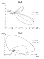
- the characteristic obtained, called “cardiac loop”, is illustrated Figure 3 , from in the case of a sinus rhythm (continuous loop) and in the case of a TSV episode (dashed loop), in the same patient.
- Each of these loops is representative of a complete heart beat, either in sinus rhythm or in TSV.
- the invention proposes, essentially, to systematize this approach by analyzing the characteristics of the 2D vectogram, with respect to a corresponding reference vectogram obtained in sinus rhythm.
- This typical value of 80 ms makes it possible to isolate the QRS complex to analyze the morphology, without too much noise around, noise corresponding to the baseline after the end of the QRS.
- the device stores a plurality of successive beats, for example the last eight beats B 1 to B 8 , as illustrated. Figure 5 these beats being recorded simultaneously on the ventricular bipolar pathway (BipV) and the unipolar ventricular pathway (UnipV).
- the fraction of each of these beats included inside the window W is then represented in the form of a vectogram, considered in the plane consisting of the bipolar path on the abscissa and the unipolar path on the ordinate. It should be noted that the vectogram corresponding to each of the beats is not a closed loop, since it corresponds only to a part of the complete cardiac loop, namely the QRS complex isolated inside the window W .
- the analysis requires the prior creation of a reference beat, averaged from a succession of beats in sinus rhythm.
- the device stores the eight successive waves (step 12) and isolates the QRS complex in the window W for each of the beats collected on the bipolar path (step 14) .
- test 18 the algorithm determines whether or not to create or update the reference beat (test 18). Indeed, even if there is already a reference beat, it may be desirable to update it at regular intervals (typically at least once a day, or at least once an hour after implantation so as to take into account account the phenomenon of maturation of the electrodes after implantation of the probe), and / or depending on the patient's condition (rest / exercise, etc.).
- the algorithm selects representative beats from the eight stored beats, isolating and eliminating ESVs and miscellaneous artifacts such as poorly centered windows, and so on.
- a first, simple method for selecting representative beats consists in keeping only the complexes for which the RR intervals are stable, and averaging the complexes satisfying these criteria point by point.
- Another method illustrated with reference to Figures 8 and 9 consists in analyzing the morphology of the eight beats by cross correlation.
- a beat is taken at random as a reference, for example the fourth of the eight beats of the Figure 5 (which in this case is an ESV).
- a correlation coefficient is calculated between this reference beat and each of the other seven beats, and this for both the bipolar signal and the unipolar signal.
- the slow rate reference beat is calculated by averaging the eight beats, for each of the two bipolar and unipolar pathways (steps 22 and 22 'on the Figure 7 ).
- the algorithm chooses the cluster with the largest number of elements, namely the cluster at the bottom left on the Figure 8 .
- the reference beat in slow rhythm is calculated on each of the two bipolar and unipolar paths (steps 22 and 22 ') by means of point by point the beats corresponding to the selected cluster : in the example, it will be the vectograms referenced "RS" of the Figure 9 , corresponding to the "RS" cluster of the Figure 8 , which will be averaged point-to-point to get the reference beat, while the two vectograms referenced "ESV" on the Figure 9 , corresponding to the two beats B 4 and B 8 of the "ESV" cluster of the Figure 8 , will be eliminated because they correspond to ESV (or artifacts).
- the algorithm determines a vectogram of the reference beat (step 24 of the Figure 7 ), by plotting the variations of the bipolar path as the abscissa and the unipolar path as the ordinate, for each of the sampling points of the signals inside the window W.
- This vectogram is then characterized in each of its points.
- the invention proposes, for example, to carry out this characterization with two descriptors ( Figure 10 ): the unit tangent vector e T and the curvature c (inverse of the radius of curvature r ) at the point P of the reference vectogram VG REF , and this for the different sampled successive points of the vectogram (steps 26 and 26 'of the Figure 7 ).
- Another possible descriptor is the norm of the tangent vector.
- the unit tangent vector e T at a given point can be determined by a technique in itself known, in particular with a discrete filter which approximates the first derivatives, for example on four points for a sampling frequency of 1000 Hz, this filtering being followed by a normalization (so that the tangent vector is unitary).
- the curvature c it can be calculated at a given point of the vectogram from the first derivatives and the second derivatives, calculated analogously to the first derivatives.
- the curvature is then weighted by a power of the distance between the points. This distance is calculated from a discrete filter applied to the Euclidean distances between two successive points in the vectogram space. Finally the curvature is normalized.
- the reference vectogram was thus determined, and characterized by its tangent vector and its curvature at each point.
- the device will then be able to determine the nature of this tachycardia by a morphological analysis involving a comparison with the reference vectogram thus defined.
- the general tachycardia classification algorithm is illustrated Figure 11 .
- the device detects and stores the last eight beats, keeping only the information centered on a window W around the depolarization peak of the bipolar signal (steps 30, 32 and 34).
- the procedure is the same as that explained above with reference to the Figure 5 , steps 30, 32 and 34 being similar to steps 10, 12 and 14 previously explained.
- the algorithm can possibly condition the continuation of the morphological analysis to the existence of a TV previously confirmed by rhythmic analysis (test 36); for example, by algorithms such as PARAD, PARAD + or STABILITY + implemented in medical ELA devices and described in the aforementioned documents EP 0 626 182 A1 (ELA Medical) and others.
- rhythm analysis and morphological analysis will be described later with reference to the Figure 14 , but it may already be noted that the conditioning of the morphological analysis to the prior detection of a TV by rhythmic analysis is not a necessary characteristic of the implementation of the invention, and that step 36 so is an optional step.
- the next step (step 38) is to trace the vectograms of the last eight beats, and to characterize them in each of their points by the two descriptors (unit tangent vector and weighted and normalized curvature).
- this corresponds to a quadratic function of the heart rate, which is calculated on the training set by conventional supervised classification methods, such as the least squares method.
- Supervised classification consists in inferring from a sample of classified data a decision boundary separating the two classes by minimizing the quadratic (least squares) error between the true values (for example 1 for TV and -1 for TSV) and the values predicted by the classifier.
- the Figure 14 is a block diagram showing how it is possible to combine rhythmic analysis (according to known techniques) and morphological analysis (according to the invention) to allow the device to make a global decision on the classification of the arrhythmia, and thus on whether or not to apply a defibrillation shock to the patient.
- atrio-ventricular association is 1: 1, because in this case the acceleration is sudden and the origin of this acceleration is not obvious (atrial tachycardia ventricular tachycardia). Or when the RR intervals are stable and there is no atrio-ventricular association (atrial fibrillation / ventricular tachycardia), because the rhythmic analysis is often insufficient to determine for sure the origin of the arrhythmia.
- morphological analysis helps to avoid inappropriate shocks. Indeed, the conjunction of a situation with stable RR intervals, sudden acceleration and absence of a long cycle, considered by rhythmic analysis as requiring therapy, can very well characterize in certain situations a supraventricular tachycardia, which does not justify such a situation. therapy.
- the morphological analysis according to the invention will, precisely, to discriminate such a situation.
- the device operates concurrently a rhythm analysis (step 62) and a morphological analysis (step 64 in the manner explained above on the Figure 11 ).
- the rhythmic analysis operates the classification between TV, TSV or non-significant arrhythmia (no majority on the eight beats) and the morphological analysis does the same.
- This second embodiment is also based on the analysis and characterization of the vectogram, but on the basis of criteria other than those described above with regard to the first embodiment (unit tangent vector and normalized weighted curvature). in each point). Considerations as to how it is possible to combine rhythmic analysis and morphological analysis, explained in particular in relation to the Figure 14 , remain however perfectly applicable to this second mode of implementation.
- This ACP analysis which is a technique in itself known, can be performed for each beat, and it allows to deduce the electric axis of the heart, which is an indicator of the general direction that the electric wave takes when it spreads in the ventricles: the path of greatest dynamics is the one with the largest projection, the corresponding direction being called the "main axis"; this axis can be completed by two other axes called “secondary axes, perpendicular to each other and to the main axis.
- the technique of the invention makes it possible to discriminate between TV and TSV from only two electrodes, which allows an implementation of this technique in a single chamber defibrillator.
- the analysis of a 2D characteristic is sufficient to achieve the desired goal, in an improved implementation the analysis can be performed on the basis of a 3D characteristic, obtained from three electrodes.
- S1 and S2 be the two signals on the respective channels A (BipV) and B (UnipV) representing a cardiac beat averaged for example over fifteen successive sinus beats.
- Each signal consists of N points represented in the database of the electrodes (A, B), the coordinates of the ith point being (S 1 (i), S 2 (i)).
- the eigenvector with the greatest eigenvalue thus gives the direction of the greatest scatter scatter.
- the eigenvalues ( ⁇ i ) i 1.2 and the eigenvectors ( V1 , V2) associated with the matrix C are then calculated.
- P - 1 P 1 P 2
- P i the column vector i of the base ACP (that is to say the eigenvector associated with the eigenvalue ⁇ i ) expressed in the base ( A , B ).
- the base ACP is calculated on the basis of the sinus rhythm, before projecting the sinus rhythm data and the tachycardia data on this same basis.
- the Figure 15 illustrates the result obtained after this basic change, for a patient with RS sinus rhythm (continuous loop) and episodes of supraventricular tachycardia TSV (dashed loop).
- the Figure 16 is counterpart of the Figure 15 , for a patient with RS sinus rhythm (continuous loop) and TV ventricular tachycardia episodes (dashed loop).
- the next step of the analysis consists in determining a certain number of descriptors parameters of the morphology of these loops so as to be able, under the best conditions, to discriminate between TV and TSV for a patient presenting episodes of tachycardia.
- each signal (sinus rhythm and tachycardia) is then projected on its own base, so as to be able to observe the corresponding one-dimensional signal (which is therefore a signal in the time domain), then compare the shapes in order to extract the morphological parameters that differentiate the SVTs from the VTs.
- the algorithm then calculates correlation coefficients between, on the one hand, the signals RS and TSV and, on the other hand, the signals RS and TV, these coefficients being calculated on the main channel and the secondary way.
- the mean squared error with respect to the sinus rhythm is also calculated, for the TSV beats and for the TV beats.
- D 1 ⁇ 1 / ⁇ 2 SR ⁇ 1 / ⁇ 2 TR
- D 2 ⁇ 1 / ⁇ 1 + ⁇ 2 SR ⁇ 1 / ⁇ 1 + ⁇ 2 TR
- D 4 R 1 , SR R 1 , TR
- D 5 R 2 , SR R 2 , TR
- the discrimination between TV and TSV can then be performed by various types of classifiers, in particular by a linear classifier or by a neural classifier.
- a first mode of implementation consists in constructing a linear classifier in the 3D space formed for example by the three descriptors EQM, M 1 and D 1 (this method can be applied to other descriptors).
- Such a classifier is characterized by the equation of the plane separating in this space the two families of arrhythmias, TV and TSV.
- a robust separator plane can be obtained by minimizing the least squares of the distance of each example to the plane.
- Matrix X is the matrix containing for each arrhythmia the value of the three descriptors in columns, and a fourth column of 1. This matrix has the following structure, assuming that we have a database of patients with 1 to N arrhythmias: MSE 1 ⁇ M 1 1 ⁇ D 1 1 1 MSE 2 ⁇ M 1 2 ⁇ D 1 2 1 . .. . . . MSE NOT ⁇ M 1 NOT ⁇ D 1 NOT 1
- the matrix Y is the vector consisting of -1 when the point corresponds to a TSV, and of 1 if the point corresponds to a TV.
- the ratios R 1, SR and R 2, SR respectively between the maximum amplitude and the minimum amplitude of the depolarization complex on the BipV and UnipV axes from the patient's sinus rhythm EGM, as well as the ratios R 1, TR and R 2, TR for tachycardia beats can be determined without the use of principal components analysis.
- the correlation maxima M 1 and M 2 can be determined between the sinus beat and the tachycardia beat plots, respectively on the BipV and UnipV axes.
- the database is scalable and continuously complete in the device, each arrhythmia to be added or replace the arrhythmia of the database. Moreover, the device, implant or programmer recalculates the matrix A at regular intervals.
- Another embodiment may, alternatively, implement a neural classifier, which allows in particular to operate by means of an adaptive network, instead of a purely mathematical calculation.
- This classifier is constructed in the 3D space formed for example by the three descriptors EQM, M 1 and D 1 (this method can be applied to other descriptors).
- the database is scalable and continuously complete in the device, each arrhythmia to be added or replace the arrhythmia of the database. Moreover, the device, implant or programmer remakes at regular intervals the training of W.
- the device may comprise complementary means for checking a posteriori classification arrhythmia, the same type as those discussed above, leading to a new learning of W at regular intervals in the event of misclassification.
Abstract
Description
L'invention concerne une technique d'analyse des tachyarythmies ventriculaires.The invention relates to a technique for analyzing ventricular tachyarrhythmias.
Elle est notamment applicable aux dispositifs médicaux implantables actifs (au sens de la directive 90/385/CEE du 20 juin 1990 du Conseil des communautés européennes), et plus particulièrement aux appareils permettant d'appliquer au coeur des thérapies impliquant la délivrance contrôlée d'impulsions électriques de haute énergie destinées à mettre fin à une tachyarythmie, et/ou des thérapies par stimulation à haute fréquence dites ATP (AntiTachycardia Pacing).It is particularly applicable to active implantable medical devices (within the meaning of Council of European Communities Directive 90/385 / EEC of 20 June 1990), and more particularly to devices making it possible to apply at the heart therapies involving controlled delivery of high energy electrical impulses for terminating a tachyarrhythmia, and / or high frequency stimulation therapies called ATP ( AntiTachycardia Pacing ).
On notera cependant que l'invention peut être mise en oeuvre non seulement au sein d'un implant, mais également à l'extérieur du corps du patient, par exemple dans un programmateur externe utilisé par un praticien pour télécharger et analyser les signaux cardiaques recueillis et mémorisés par l'implant. L'invention peut également être mise en oeuvre dans un moniteur de "home monitoring", qui est un type particulier de programmateur dont le fonctionnement est entièrement automatisé ; un tel moniteur ne nécessite pas le recours à un praticien, et permet notamment de télé-transmettre à intervalles réguliers à un site distant des données recueillies par un implant, pour analyse et suivi du patient. L'invention peut être également mise en oeuvre au niveau du serveur de données de ce site, à partir des données transmises telles quelles par le moniteur du patient.It should be noted, however, that the invention can be implemented not only within an implant, but also outside the patient's body, for example in an external programmer used by a practitioner to download and analyze the cardiac signals collected. and stored by the implant. The invention can also be implemented in a "home monitoring" monitor, which is a particular type of programmer whose operation is fully automated; such a monitor does not require the use of a practitioner, and allows in particular to remotely transmit to a remote site data collected by an implant, for analysis and monitoring of the patient. The invention can also be implemented at the data server of this site, from the data transmitted as is by the patient monitor.
De façon générale une tachyarythmie (un rythme cardiaque rapide anormal) peut être d'origine sinusale, auriculaire ou ventriculaire.In general, a tachyarrhythmia (abnormal rapid heartbeat) may be of sinus, atrial or ventricular origin.
Mais il n'est pas toujours simple de déterminer l'origine d'une tachycardie avérée. Or, dans le cas d'un appareil susceptible par exemple d'appliquer une thérapie telle que la délivrance d'un choc de défibrillation, un tel choc ne doit être délivré que dans le cas d'une véritable tachycardie ventriculaire (TV), et non d'une tachycardie supraventriculaire (TSV). En effet, dans ce dernier cas, la tachycardie est d'origine auriculaire, et le choc qui serait délivré serait sans effet puisque l'électrode de défibrillation ne se trouve pas dans cette région.But it is not always easy to determine the origin of a proven tachycardia. However, in the case of an apparatus capable, for example, of applying a therapy such as the delivery of a defibrillation shock, such a shock must be delivered only in the case of true ventricular tachycardia (VT), and no supraventricular tachycardia (SVT). Indeed, in the latter case, the tachycardia is of atrial origin, and the shock that would be delivered without effect since the defibrillation electrode is not in this region.
Or l'application d'un choc de défibrillation chez un patient conscient est extrêmement douloureuse et angoissante, les énergies appliquées étant en effet très au-delà du seuil de douleur. En outre, l'application d'un choc de défibrillation n'est pas dénuée d'effets secondaires sur le rythme cardiaque (risque d'apparition de troubles secondaires), sur l'intégrité fonctionnelle du myocarde, et de façon générale sur l'équilibre physiologique du patient.However, the application of a shock of defibrillation in a conscious patient is extremely painful and distressing, the applied energies being indeed well beyond the threshold of pain. In addition, the application of a defibrillation shock is not devoid of side effects on the heart rate (risk of occurrence of secondary disorders), on the functional integrity of the myocardium, and generally on the physiological balance of the patient.
Il est donc important de ne délivrer de tels chocs que de façon appropriée et seulement si une autre thérapie moins douloureuse, telle qu'une stimulation appropriée de l'oreillette, n'est pas envisageable.It is therefore important to deliver such shocks only in an appropriate manner and only if other less painful therapy, such as appropriate stimulation of the atrium, is not possible.
Plus précisément, une tachycardie peut recouvrir diverses formes de troubles du rythme cardiaque : lorsque l'on se trouve en présence d'une tachyarythmie, celle-ci peut avoir pour cause une fibrillation ventriculaire (FV), une tachycardie ventriculaire (TV), une tachycardie sinusale (TS) ou une tachycardie supraventriculaire (TSV). La TSV recouvre elle-même la tachycardie auriculaire, le flutter auriculaire et la fibrillation auriculaire (FA). Ces troubles peuvent d'ailleurs se superposer et l'on parle alors de "bitachycardie", notamment en présence d'une fibrillation auriculaire combinée à une tachycardie ventriculaire.Specifically, tachycardia can include various forms of cardiac arrhythmias: when tachyarrhythmia is present, it may be due to ventricular fibrillation (VF), ventricular tachycardia (VT), sinus tachycardia (TS) or supraventricular tachycardia (TSV). TSV itself covers atrial tachycardia, atrial flutter and atrial fibrillation (AF). These disorders can also be superimposed and it is called "bitachycardia", especially in the presence of atrial fibrillation combined with ventricular tachycardia.
Toute la difficulté vient du fait que, dans bon nombre de situations pathologiques, certains événements pourtant présents ne sont pas visibles, car masqués par d'autres événements concomitants. Ainsi, les complexes larges d'une TV rapide rendent souvent difficile la reconnaissance des ondes P, ce qui ne permet pas toujours de les différencier de ceux d'un flutter associé à un bloc de branche fonctionnel.The difficulty lies in the fact that, in many pathological situations, certain events that are present are not visible because they are masked by other concomitant events. Thus, the large complexes of a fast TV often make it difficult to recognize the P waves, which does not always make it possible to differentiate them from those of a flutter associated with a functional branch block.
La reconnaissance de ces phénomènes masqués, et des ondes P en particulier, est donc un élément fondamental dans ce domaine.The recognition of these masked phenomena, and P waves in particular, is therefore a fundamental element in this field.
Or, si cette reconnaissance est difficile pour le clinicien, elle l'est encore plus pour les systèmes d'analyse automatique du rythme cardiaque. Les critères de discrimination employés par ces dispositifs comprennent en particulier la fréquence ventriculaire, la stabilité des intervalles ventriculaires (intervalles RR), l'analyse de l'association auriculo-ventriculaire (révélée par la stabilité de l'intervalle PR) et le mode de démarrage des tachycardies (présence d'une accélération brusque et cavité d'origine, ventriculaire ou auriculaire).However, if this recognition is difficult for the clinician, it is even more difficult for automatic cardiac rhythm analysis systems. The discrimination criteria employed by these devices include in particular the ventricular rate, the stability of the ventricular intervals (RR intervals), the analysis of the atrioventricular association (revealed by the stability of the PR interval) and the mode of start of tachycardias (presence of sudden acceleration and original cavity, ventricular or atrial).
On pourra notamment se référer au
D'autres propositions ont également été formulées pour opérer la discrimination entre TV et TSV à partir d'une analyse morphologique du complexe QRS seul, ne faisant donc pas intervenir l'onde P difficile à reconnaître.Other proposals have also been formulated to discriminate between TV and TSV from a morphological analysis of the QRS complex alone, thus not making the P-wave difficult to recognize.
Ces techniques basées sur une analyse morphologique du QRS sont le plus souvent utilisées par les cardiologues en pratique clinique, lorsqu'ils analysent un tracé ECG pour caractériser les arythmies ventriculaires qui sont généralement les plus menaçantes.These techniques based on morphological analysis of the QRS are most often used by cardiologists in clinical practice, when they analyze an ECG tracing to characterize the ventricular arrhythmias that are usually the most threatening.
Mais l'application de ces méthodes à des algorithmes de détection automatique pour prothèse cardiaques implantées n'est pas suffisamment fiable, en partie parce que l'information potentielle contenue dans les signaux d'électrogramme endocavitaire (EGM) recueillis par ces prothèses n'est pas complètement maîtrisée, en tout état de cause beaucoup moins que les signaux d'électrocardiogramme (ECG) recueillis par un enregistreur externe. En particulier, les paramètres de normalité de ces signaux sont largement méconnus, ce qui ne permet pas de distinguer par comparaison les situations pathologiques de celles qui ne le sont pas.But the application of these methods to automatic detection algorithms for implanted cardiac prostheses is not sufficiently reliable, in part because the potential information contained in the endocaval electrogram (EGM) signals collected by these prostheses is not sufficiently reliable. not completely controlled, in any case much less than electrocardiogram (ECG) signals collected by an external recorder. In particular, the parameters of normality of these signals are largely unknown, which makes it impossible to distinguish by comparison the pathological situations from those which are not.
S'y ajoute le fait que les algorithmes d'analyse, complexes, impliquent souvent, en termes de puissance de calcul et surtout de consommation énergétique, des moyens incompatibles avec ce qui est disponible à l'intérieur d'un dispositif miniature implanté. Ceci conduit à proposer des solutions algorithmiques sous-optimales qui ne permettent pas d'établir un diagnostic d'une fiabilité suffisante.Added to this is the fact that the analysis algorithms, complex, often involve, in terms of computing power and especially energy consumption, means incompatible with what is available inside an implanted miniature device. This leads to proposing sub-optimal algorithmic solutions that do not make it possible to establish a diagnosis of sufficient reliability.
Il existe aujourd'hui différents algorithmes pour défibrillateurs implantables, basés sur une analyse morphologique.Today, there are different algorithms for implantable defibrillators, based on morphological analysis.
Ces algorithmes mettent en oeuvre des méthodes basées sur la propriété suivante : lors d'un épisode de TSV, les impulsions électriques empruntent dans les ventricules les mêmes voies de conduction qu'en rythme sinusal, de sorte que la morphologie du signal de contraction ventriculaire est très similaire à celle du signal enregistré en rythme sinusal. A l'inverse, pendant un épisode de TV, les voies de conductions étant différentes, le signal électrique enregistré est différent.These algorithms use methods based on the following property: during an episode of TSV, the electrical impulses borrow in the ventricles the same conduction pathways as in sinus rhythm, so that the morphology of the ventricular contraction signal is very similar to that of the signal recorded in sinus rhythm. Conversely, during a TV episode, the conduction paths being different, the recorded electrical signal is different.
Ces méthodes proposent donc d'effectuer la discrimination TV/TSV à partir d'une mesure de la ressemblance des signaux enregistrés pendant l'arythmie à ceux enregistrés en rythme sinusal.These methods therefore propose to discriminate TV / SVT from a measure of the similarity of the signals recorded during the arrhythmia to those recorded in sinus rhythm.
Le
Une autre méthode, dénommée "MD" (Morphology Discrimination) et décrite dans
Le
En tout état de cause, quelle que soit la technique mise en oeuvre, les algorithmes proposés jusqu'à présent continuent néanmoins à être leurrés dans certaines situations cliniques particulières, avec souvent pour conséquence un faux diagnostic de TV et donc le risque d'appliquer une thérapie inappropriée.In any case, regardless of the technique used, the algorithms proposed so far still continue to be deceived in certain particular clinical situations, often resulting in a false diagnosis of TV and therefore the risk of applying a inappropriate therapy.
Le but de l'invention est de remédier aux inconvénients précités, en proposant une nouvelle technique d'analyse permettant d'éliminer quasiment tout risque de faux diagnostic de TV (faux positif ou faux négatif) lors de la discrimination entre TV et TSV, donc de réduire le nombre de chocs inappropriés dus à une mauvaise discrimination, et ceci dans toutes les situations cliniques susceptibles d'être rencontrées, assurant donc une plus grande fiabilité d'analyse des tachyarythmies.The object of the invention is to overcome the aforementioned drawbacks, by proposing a new analysis technique to virtually eliminate any risk of false diagnosis of TV (false positive or false negative) when discrimination between TV and TSV, so to reduce the number of inappropriate shocks due to poor discrimination, and this in all clinical situations likely to be encountered, thus ensuring greater reliability of tachyarrhythmia analysis.
En d'autres termes, le but de l'invention est d'améliorer la prise de décision des défibrillateurs implantables dans la discrimination entre TV etIn other words, the object of the invention is to improve the decision-making of implantable defibrillators in the discrimination between TV and
TSV, en gagnant en spécificité sans compromettre la sensibilité.TSV, gaining in specificity without compromising sensitivity.
L'idée de base de l'invention réside dans la constatation de ce que des paramètres pertinents de discrimination entre TV et TSV peuvent être obtenus en analysant des signaux EGM provenant de la même cavité (le ventricule) et recueillis concurremment sur deux voies distinctes, ces signaux étant combinés entre eux sous forme de deux composantes respectives appliquées à une analyse bidimensionnelle - en faisant donc abstraction de la dimension temporelle.The basic idea of the invention lies in the observation that relevant discrimination parameters between TV and SVV can be obtained by analyzing EGM signals originating from the same cavity (the ventricle) and collected concurrently on two distinct pathways, these signals being combined with each other in the form of two respective components applied to a two-dimensional analysis - thus disregarding the temporal dimension.
Les deux voies EGM différentes sont par exemple celle du signal unipolaire (recueilli entre le boîtier et l'une des électrodes distale ou proximale), et celle du signal bipolaire (recueilli entre les deux électrodes distale et proximale).The two different EGM channels are for example that of the unipolar signal (collected between the housing and one of the distal or proximal electrodes), and that of the bipolar signal (collected between the two distal and proximal electrodes).
On notera incidemment que l'analyse 'bidimensionnelle" ou "en deux dimensions" (2D) ne doit pas être entendue de manière en elle-même limitative, et que l'invention s'applique aussi bien à une analyse dans un espace multidimensionnel d'ordre supérieur (3D ou plus), par extrapolation des enseignements de la présente description à une situation où des signaux EGM provenant d'une même cavité sont recueillis simultanément sur trois voies ou plus.It should be noted incidentally that the "two-dimensional" or "two-dimensional" analysis (2D) must not be understood in a way that is in itself limiting, and that the invention applies equally well to an analysis in a multidimensional space. higher order (3D or more), by extrapolation of the teachings of the present description to a situation where EGM signals from the same cavity are collected simultaneously on three or more channels.
L'invention propose, comme avec les méthodes existantes, d'effectuer la discrimination TV/TSV à partir d'une mesure de la ressemblance des signaux enregistrés pendant l'arythmie à ceux enregistrés en rythme sinusal.The invention proposes, as with existing methods, to discriminate TV / SVV from a measurement of the similarity of the signals recorded during the arrhythmia to those recorded in sinus rhythm.
En revanche, et de façon caractéristique, cette discrimination TV/TSV est opérée à partir de la "boucle cardiaque" ou "vectogramme", qui est la représentation de l'un de ces signaux par rapport à l'autre, dans un espace à deux dimensions. Cet espace est typiquement un espace "voie unipolaire (en ordonnée) vs. voie bipolaire (en abscisse)". Chaque battement (ou fraction significative de battement) est alors représenté par son vectogramme dans le plan ainsi défini. En cas d'arythmie, le battement est comparé à un vectogramme de référence correspondant, obtenu en rythme sinusal. L'algorithme estime la plus ou moins grande similitude avec ce vectogramme de référence et discrimine en conséquence le type d'arythmie, TV (faible similitude) ou TSV (forte similitude).On the other hand, and in a characteristic way, this discrimination TV / TSV is operated from the "cardiac loop" or "vectogram", which is the representation of one of these signals with respect to the other, in a space to two dimensions. This space is typically a space "unipolar path (ordinate) vs. bipolar path (abscissa)". Each beat (or significant fraction of beat) is then represented by its vectogram in the plane thus defined. In case of arrhythmia, the beat is compared to a corresponding reference vectogram obtained in sinus rhythm. The algorithm estimates the greater or less similarity with this reference vectogram and discriminates accordingly the type of arrhythmia, TV (low similarity) or TSV (strong similarity).
Plus précisément, l'invention propose un dispositif médical actif du type divulgué par le
Les sous-revendications 2 à 13 visent une première forme de mise en oeuvre, préférentielle, de l'invention, où chaque vectogramme (rythme sinusal et arythmie) est caractérisé par son vecteur tangent et sa courbure en chaque point.The
Les sous-revendications 14 à 29 visent une seconde forme de mise en oeuvre de l'invention, où le vectogramme est caractérisé par projection dans une base orthonormée définie à partir du rythme sinusal par une analyse en composantes principales.
On va maintenant décrire un exemple de mise en oeuvre du dispositif de l'invention, en référence aux dessins annexés où les mêmes références numériques désignent d'une figure à l'autre des éléments identiques ou fonctionnellement semblables.
- La
Figure 1 illustre les signaux d'électrogramme obtenus, respectivement sur les voies bipolaire ventriculaire et unipolaire ventriculaire, pour un patient présentant un rythme sinusal. - La
Figure 2 est homologue de laFigure 1 , lors d'un épisode de tachycardie supraventriculaire. - La
Figure 3 illustre les boucles cardiaques obtenues en combinant les deux signaux desFigures 1 pour un même patient, en rythme sinusal et lors d'un épisode de tachycardie supraventriculaire.et 2 - La
Figure 4 est homologue de laFigure 3 , pour un même patient en rythme sinusal et lors d'un épisode de tachycardie ventriculaire. - La
Figure 5 illustre, pour un premier mode de mise en oeuvre de l'invention, des signaux d'électrogramme typiquement recueillis sur les voies bipolaire ventriculaire et unipolaire ventriculaire simultanément enregistrées pour un patient donné. - La
Figure 6 illustre le vectogramme obtenu en combinant les deux signaux de laFigure 5 , pour huit battements successifs. - La
Figure 7 est un organigramme illustrant les différentes étapes de l'algorithme d'estimation du battement de référence en rythme sinusal. - Les
Figures 8 et 9 illustrent la manière dont est analysée la corrélation entre les battements, destinée à discriminer entre battements en rythme sinusal et extrasystoles ventriculaires. - La
Figure 10 illustre deux paramètres de caractérisation d'un vectogramme en un point donné, à savoir la courbure et le vecteur tangent unitaire en ce point. - La
Figure 11 est un organigramme illustrant les différentes étapes de l'algorithme de classification morphologique destiné à déterminer la nature, ventriculaire ou supraventriculaire, d'une tachycardie détectée chez un patient. - La
Figure 12 illustre graphiquement les différents paramètres calculés par l'algorithme de caractérisation pour un même patient, respectivement en rythme sinusal et lors d'un épisode de tachycardie supraventriculaire, ainsi que la manière d'analyser ces paramètres pour en déduire la nature de cette tachycardie. - La
Figure 13 est homologue de laFigure 12 , pour un patient en rythme sinusal et lors d'un épisode de tachycardie ventriculaire. - La
Figure 14 est un schéma synoptique montrant la manière dont l'analyse morphologique selon l'invention peut être combinée à une analyse rythmologique pour améliorer la spécificité d'un dispositif existant. - La
Figure 15 illustre, pour un second mode de mise en oeuvre de l'invention, les boucles cardiaques obtenues, respectivement dans le cas d'un rythme sinusal et d'une tachycardie supraventriculaire, lorsque les composantes de ces boucles sont projetées dans la base définie par le rythme sinusal. - La
Figure 16 est homologue de laFigure 15 , pour un rythme sinusal et une tachycardie ventriculaire. - La
Figure 17 illustre les variations des signaux correspondant à un rythme sinusal et à une tachycardie ventriculaire, lorsque ces signaux sont projetés sur l'axe principal et sur l'axe secondaire de la boucle cardiaque, ces axes ayant été déterminés par une analyse en composantes principales, selon le second mode de mise en oeuvre de l'invention. - La
Figure 18 illustre une technique permettant, après analyse de corrélation, de discriminer entre tachycardies ventriculaires et tachycardies supraventriculaires à partir d'une distribution caractéristique des résultats de la corrélation, toujours selon le second mode de mise en oeuvre de l'invention.
- The
Figure 1 illustrates the electrogram signals obtained, respectively on the ventricular and unipolar ventricular bipolar pathways, for a patient presenting a sinus rhythm. - The
Figure 2 is counterpart of theFigure 1 , during an episode of supraventricular tachycardia. - The
Figure 3 illustrates the cardiac loops obtained by combining the two signals ofFigures 1 and 2 for the same patient, in sinus rhythm and during an episode of supraventricular tachycardia. - The
Figure 4 is counterpart of theFigure 3 , for the same patient in sinus rhythm and during an episode of ventricular tachycardia. - The
Figure 5 illustrates, for a first embodiment of the invention, electrogram signals typically collected on the ventricular and unipolar ventricular bipolar pathways simultaneously recorded for a given patient. - The
Figure 6 illustrates the vectogram obtained by combining the two signals of theFigure 5 , for eight successive beats. - The
Figure 7 is a flow diagram illustrating the different steps of the algorithm for estimating the reference beat in sinus rhythm. - The
Figures 8 and 9 illustrate how the correlation between beats is analyzed to discriminate between sinus rhythm beats and ventricular extrasystoles. - The
Figure 10 illustrates two parameters of characterization of a vectogram at a given point, namely the curvature and the unit tangent vector at this point. - The
Figure 11 is a flowchart illustrating the different steps of the morphological classification algorithm for determining the ventricular or supraventricular nature of a tachycardia detected in a patient. - The
Figure 12 Graphically illustrates the different parameters calculated by the characterization algorithm for the same patient, respectively in sinus rhythm and during a supraventricular tachycardia episode, as well as the manner of analyzing these parameters in order to deduce the nature of this tachycardia. - The
Figure 13 is counterpart of theFigure 12 , for a patient in sinus rhythm and during a ventricular tachycardia episode. - The
Figure 14 is a block diagram showing how the morphological analysis according to the invention can be combined with a rhythmic analysis to improve the specificity of an existing device. - The
Figure 15 illustrates, for a second embodiment of the invention, the cardiac loops obtained, respectively in the case of a sinus rhythm and a supraventricular tachycardia, when the components of these loops are projected in the base defined by the sinus rhythm. - The
Figure 16 is counterpart of theFigure 15 for sinus rhythm and ventricular tachycardia. - The
Figure 17 illustrates the variations of the signals corresponding to sinus rhythm and ventricular tachycardia, when these signals are projected on the main axis and on the secondary axis of the cardiac loop, these axes having been determined by a principal component analysis, according to the second embodiment of the invention. - The
Figure 18 illustrates a technique allowing, after correlation analysis, to discriminate between ventricular tachycardias and supraventricular tachycardias from a characteristic distribution of the results of the correlation, again according to the second embodiment of the invention.
On va maintenant décrire deux exemples de réalisation de l'invention, appliqués à un dispositif médical implantable actif permettant de surveiller en continu le rythme cardiaque et délivrer si nécessaire au coeur des impulsions électriques de stimulation, de resynchronisation et/ou de défibrillation en cas de trouble du rythme détecté par cet implant.Two examples of embodiment of the invention will now be described, applied to an active implantable medical device for continuously monitoring the heart rate and, if necessary, delivering electrical pulses of stimulation, resynchronization and / or defibrillation in case of heart failure. rhythm disorder detected by this implant.
En ce qui concerne ses aspects logiciels, l'invention peut être mise en oeuvre par une programmation appropriée du logiciel de commande d'un dispositif connu, par exemple de type stimulateur cardiaque ou défibrillateur, comprenant des moyens d'acquisition d'un signal fourni par des sondes endocavitaires.With regard to its software aspects, the invention can be implemented by appropriate programming of the control software of a known device, for example of the pacemaker or defibrillator type, comprising means for acquiring a signal provided. by endocavitary probes.
L'invention peut notamment être appliquée à des dispositifs implantables tels que les appareils de la gamme Ovatio commercialisés par ELA Médical, Montrouge, France. Il s'agit de dispositifs à microprocesseur programmable auxquels est possible de transmettre par télémétrie des logiciels qui seront conservés en mémoire et exécutés pour mettre en oeuvre les fonctions de l'invention qui seront décrites ci-dessous. L'adaptation de ces appareils à la mise en oeuvre des fonctions de l'invention est à la portée de l'homme du métier, et elle ne sera pas décrite en détail.The invention can in particular be applied to implantable devices such as the devices of the Ovatio range marketed by ELA Medical, Montrouge, France. These are programmable microprocessor devices to which it is possible to transmit by telemetry software that will be stored in memory and executed to implement the functions of the invention which will be described below. The adaptation of these devices to the implementation of the functions of the invention is within the abilities of those skilled in the art, and it will not be described in detail.
Comme cela a été indiqué plus haut, la technique d'analyse de l'invention consiste à opérer une discrimination entre tachycardies ventriculaires TV (ou VT) et tachycardies supraventriculaires TSV (ou SVT) à partir des signaux d'électrogramme EGM recueillis sur deux voies distinctes et analysés en deux dimensions.As indicated above, the assay technique of the invention consists in discriminating between ventricular TV (or VT) tachycardias and supraventricular tachycardias TSV (or SVT) from the two-way EGM electrogram signals. distinct and analyzed in two dimensions.
La
La
Ces signaux font l'objet d'un prétraitement approprié de filtrage, normalisation et centrage (ce prétraitement, classique en lui-même, ne faisant pas partie de l'invention).These signals are subject to appropriate pretreatment filtering, normalization and centering (this pretreatment, conventional in itself, not part of the invention).
L'étape suivante consiste, une fois ces signaux recueillis (dans le domaine temporel), à tracer l'un des signaux en fonction de l'autre. La caractéristique obtenue, dénommée "boucle cardiaque", est illustrée
Chacune de ces boucles est représentative d'un battement cardiaque complet, soit en rythme sinusal, soit en TSV.Each of these loops is representative of a complete heart beat, either in sinus rhythm or in TSV.
On verra toutefois plus bas qu'il n'est pas indispensable d'analyser la totalité du battement, mais que l'analyse d'une fraction significative de ce battement (typiquement, celle centrée autour du complexe QRS) est en général suffisante pour opérer la discrimination recherchée.However, it will be seen below that it is not essential to analyze the whole of the beat, but that the analysis of a significant fraction of this beat (typically that centered around the QRS complex) is generally sufficient to operate. the discrimination sought.
En comparant les deux boucles cardiaques illustrées
En revanche, sur la
L'invention propose, essentiellement, de systématiser cette approche par analyse des caractéristiques du vectogramme 2D, par rapport à un vectogramme de référence correspondant, obtenu en rythme sinusal.The invention proposes, essentially, to systematize this approach by analyzing the characteristics of the 2D vectogram, with respect to a corresponding reference vectogram obtained in sinus rhythm.
On va maintenant décrire un premier mode de mise en oeuvre de l'invention, en référence aux
Dans cette approche, après chaque détection d'un pic de dépolarisation du signal bipolaire BipV (correspondant à une onde R détectée), le battement correspondant est isolé par une fenêtre fixe W de quelques dizaines de millisecondes centrée sur ce pic de dépolarisation, par exemple une fenêtre de largeur W = 80 ms correspondant à 80 points pour une fréquence d'échantillonnage de 1000 Hz. Cette valeur typique de 80 ms permet de bien isoler le complexe QRS pour en analyser la morphologie, sans trop inclure de bruit autour, bruit correspondant à la ligne de base après la fin du QRS.In this approach, after each detection of a depolarization peak of the BipV bipolar signal (corresponding to a detected R-wave), the corresponding beat is isolated by a fixed window W of a few tens of milliseconds centered on this depolarization peak, for example a window width W = 80 ms corresponding to 80 points for a sampling frequency of 1000 Hz. This typical value of 80 ms makes it possible to isolate the QRS complex to analyze the morphology, without too much noise around, noise corresponding to the baseline after the end of the QRS.
Le dispositif garde en mémoire une pluralité de battements successifs, par exemple les huit derniers battements B1 à B8, comme illustré
La fraction de chacun de ces battements comprise à l'intérieur de la fenêtre W est alors représentée sous forme de vectogramme, considéré dans le plan constitué de la voie bipolaire en abscisse et de la voie unipolaire en ordonnée. On notera que le vectogramme correspondant à chacun des battements n'est pas une boucle fermée, dans la mesure où il ne correspond qu'à une partie de la boucle cardiaque complète, à savoir le complexe QRS isolé à l'intérieur de la fenêtre W.The fraction of each of these beats included inside the window W is then represented in the form of a vectogram, considered in the plane consisting of the bipolar path on the abscissa and the unipolar path on the ordinate. It should be noted that the vectogram corresponding to each of the beats is not a closed loop, since it corresponds only to a part of the complete cardiac loop, namely the QRS complex isolated inside the window W .
L'analyse nécessite la création préalable d'un battement de référence, moyenné à partir d'une succession de battements en rythme sinusal.The analysis requires the prior creation of a reference beat, averaged from a succession of beats in sinus rhythm.
Il est toutefois nécessaire, même en l'absence de tachycardie, d'exclure certains battements non significatifs : sur les vectogrammes tracés
Sur la
A chaque détection d'une onde R sur la voie bipolaire (étape 10), le dispositif stocke les huit ondes successives (étape 12) et isole le complexe QRS dans la fenêtre W pour chacun des battements recueillis sur la voie bipolaire (étape 14).At each detection of an R wave on the bipolar path (step 10), the device stores the eight successive waves (step 12) and isolates the QRS complex in the window W for each of the beats collected on the bipolar path (step 14) .
En l'absence de tachycardie (test 16), l'algorithme détermine s'il y a ou non besoin de créer ou actualiser le battement de référence (test 18). En effet, même s'il existe déjà un battement de référence, il peut être souhaitable de l'actualiser à intervalles réguliers (typiquement au moins une fois par jour, ou au moins une fois par heure après l'implantation de manière à prendre en compte le phénomène de maturation des électrodes après l'implantation de la sonde), et/ou en fonction de l'état du patient (repos/exercice, etc.).In the absence of tachycardia (test 16), the algorithm determines whether or not to create or update the reference beat (test 18). Indeed, even if there is already a reference beat, it may be desirable to update it at regular intervals (typically at least once a day, or at least once an hour after implantation so as to take into account account the phenomenon of maturation of the electrodes after implantation of the probe), and / or depending on the patient's condition (rest / exercise, etc.).
Dans l'affirmative, l'algorithme sélectionne les battements représentatifs parmi les huit battements mémorisés, en isolant et en éliminant les ESV et les artefacts divers tels que fenêtres mal centrées, etc.If so, the algorithm selects representative beats from the eight stored beats, isolating and eliminating ESVs and miscellaneous artifacts such as poorly centered windows, and so on.
Une première méthode, simple, de sélection des battements représentatifs consiste à ne conserver que les complexes pour lesquels les intervalles RR sont stables, et moyenner point à point les complexes répondant à ces critères.A first, simple method for selecting representative beats consists in keeping only the complexes for which the RR intervals are stable, and averaging the complexes satisfying these criteria point by point.
Une autre méthode, illustrée en référence aux
À cet effet, un battement est pris au hasard comme référence, par exemple le quatrième des huit battements de la
Si tous les coefficients de corrélation sont supérieurs à 0,9, alors le battement de référence en rythme lent est calculé en moyennant point à point les huit battements, ceci pour chacune des deux voies bipolaire et unipolaire (étapes 22 et 22' sur la
En revanche, s'il existe des valeurs inférieures à 0,9 (comme dans le cas de l'exemple illustré), alors un algorithme itératif de "clustering supervisé" est appliqué à ces huit points, par exemple de type "algorithme des K-moyennes". Un tel algorithme, en lui-même connu, consiste à partitionner les données en K classes homogènes (ici K=2, principalement pour séparer les cycles normaux des ESV) en minimisant la variance intra-classe de manière à obtenir, de manière itérative, des "clusters" (agrégats) basés sur la distance euclidienne entre les points. Pour chaque point, si sa distance au centre du cluster est supérieure à la moitié de la distance entre les deux centres des clusters respectifs, alors on considérera que ce point n'appartient à aucun cluster (ce n'est pas le cas dans l'exemple illustré
Le battement de référence en rythme lent est calculé sur chacune des deux voies bipolaire et unipolaire (étapes 22 et 22') en moyennant point à point les battements correspondant au cluster choisi : dans l'exemple, ce seront les vectogrammes référencés "RS" de la
À partir des moyennes point à point des battements sur les voies bipolaire et unipolaire, l'algorithme détermine alors un vectogramme du battement de référence (étape 24 de la
Ce vectogramme est ensuite caractérisé en chacun de ses points.This vectogram is then characterized in each of its points.
L'invention propose, par exemple, de réaliser cette caractérisation par deux descripteurs (
Un autre descripteur possible est la norme du vecteur tangent.Another possible descriptor is the norm of the tangent vector.
Le vecteur tangent unitaire
Quant à la courbure c, elle peut être calculée en un point donné du vectogramme à partir des dérivées premières et des dérivées secondes, calculées de façon analogue aux dérivées premières. Avantageusement, pour donner plus d'importance aux zones d'intérêt du vectogramme où les points sont les plus espacés, la courbure est ensuite pondérée par une puissance de la distance entre les points. Cette distance est calculée à partir d'un filtre discret appliqué sur les distances euclidiennes entre deux points successifs de l'espace du vectogramme. Finalement la courbure est normalisée.As for the curvature c, it can be calculated at a given point of the vectogram from the first derivatives and the second derivatives, calculated analogously to the first derivatives. Advantageously, for give more importance to the areas of interest of the vectogram where the points are the most spaced, the curvature is then weighted by a power of the distance between the points. This distance is calculated from a discrete filter applied to the Euclidean distances between two successive points in the vectogram space. Finally the curvature is normalized.
Le vectogramme de référence a été ainsi déterminé, et caractérisé par son vecteur tangent et sa courbure en chaque point.The reference vectogram was thus determined, and characterized by its tangent vector and its curvature at each point.
En cas de tachycardie, le dispositif sera alors en mesure de déterminer la nature de cette tachycardie par une analyse morphologique impliquant une comparaison avec le vectogramme de référence ainsi défini.In case of tachycardia, the device will then be able to determine the nature of this tachycardia by a morphological analysis involving a comparison with the reference vectogram thus defined.
L'algorithme général de classification des tachycardies est illustré
Le dispositif détecte et mémorise les huit derniers battements, en ne conservant que les informations centrées sur une fenêtre W autour du pic de dépolarisation du signal bipolaire (étapes 30, 32 et 34). La manière de procéder est la même que celle exposée plus haut en référence à la
L'algorithme peut éventuellement conditionner la poursuite de l'analyse morphologique à l'existence d'une TV confirmée préalablement par l'analyse rythmologique (test 36) ; par exemple, par des algorithmes tels que PARAD, PARAD+ ou STABILITY+ mis en oeuvre dans les dispositifs ELA Medical et décrits dans les documents précités
L'étape suivante (étape 38) consiste à tracer les vectogrammes des huit derniers battements, et de les caractériser en chacun de leurs points par les deux descripteurs (vecteur tangent unitaire et courbure pondérée et normalisée).The next step (step 38) is to trace the vectograms of the last eight beats, and to characterize them in each of their points by the two descriptors (unit tangent vector and weighted and normalized curvature).
La comparaison d'un vectogramme obtenu en tachycardie avec le vectogramme de référence obtenu en rythme sinusal pour le même patient se fait par le calcul de deux quantités :
- l'angle moyen α entre les vecteurs tangents unitaires des deux vectogrammes respectifs, et
- le coefficient de corrélation c entre les courbures des deux vectogrammes respectifs.
- the average angle α between the unit tangent vectors of the two respective vectograms, and
- the correlation coefficient c between the curvatures of the two respective vectograms.
La discrimination entre TV et TSV sera opérée sur les valeurs de α et de c par exemple par comparaison avec des seuils de décision déterminés au préalable à partir d'une base d'apprentissage. Ainsi :
- si l'angle moyen α est inférieur à une valeur donnée (étapes 40 et 42), ou si le coefficient de corrélation c est supérieur à un seuil donné dépendant de la fréquence cardiaque (étapes 46 et 48), alors le battement correspondant de l'arythmie est classé comme étant d'origine supraventriculaire (étape 44) ;
- sinon il est classé comme étant d'origine ventriculaire (étape 50).
- if the average angle α is less than a given value (
steps 40 and 42), or if the correlation coefficient c is greater than a given threshold depending on the heart rate (steps 46 and 48), then the corresponding beat of the arrhythmia is classified as being of supraventricular origin (step 44); - otherwise it is classified as being of ventricular origin (step 50).
En ce qui concerne le seuil pour le coefficient de corrélation, celui-ci correspond à une fonction quadratique de la fréquence cardiaque, cette fonction étant calculée sur l'ensemble d'apprentissage par des méthodes classiques de classification supervisée, comme la méthode des moindres carrés. La classification supervisée consiste à inférer à partir d'un échantillon de données classées une frontière de décision qui sépare les deux classes en minimisant l'erreur quadratique (au sens des moindres carrés) entre les valeurs vraies (par exemple 1 pour TV et -1 pour TSV) et les valeurs prédites par le classifieur.For the correlation coefficient threshold, this corresponds to a quadratic function of the heart rate, which is calculated on the training set by conventional supervised classification methods, such as the least squares method. . Supervised classification consists in inferring from a sample of classified data a decision boundary separating the two classes by minimizing the quadratic (least squares) error between the true values (for example 1 for TV and -1 for TSV) and the values predicted by the classifier.
L'étape suivante (étape 52) consiste à comparer les résultats obtenus pour chacun des huit battements successifs :
- si au moins six des huit battements sont classés comme étant d'origine ventriculaire, alors l'arythmie à ce stade est classée comme étant d'origine ventriculaire d'après l'analyse morphologique (étape 54) ;
- si au moins six des huit derniers battements sont classés comme étant d'origine supraventriculaire, l'arythmie à ce stade est classée comme étant d'origine supraventriculaire d'après l'analyse morphologique (étape 56) ;
- sinon, l'arythmie n'est pas classée, dans la mesure où l'analyse morphologique ne dégage aucune tendance majoritaire significative (étape 58).
- if at least six of the eight beats are classified as being of ventricular origin, then the arrhythmia at this stage is classified as being of ventricular origin according to the morphological analysis (step 54);
- if at least six of the last eight beats are classified as supraventricular, the arrhythmia at this stage is classified as supraventricular by morphological analysis (step 56);
- otherwise, the arrhythmia is not classified, since the morphological analysis does not release any significant majority trend (step 58).
Les
- les
Figures 12a et 13a montrent les vectogrammes correspondant à deux battements de référence, calculés comme précédemment en rythme sinusal pour les deux patients respectifs ; - la
Figure 12b illustre le vectogramme en TSV du premier patient, et laFigure 13b illustre le vectogramme en TV du second patient. - les
Figures 12c, 12d et 12e montrent respectivement, pour le vectogramme du battement de référence du premier patient (vectogramme de laFigure 12a ) : les variations de l'angle moyen entre le vecteur tangent unitaire et l'axe des abscisses ; la courbure brute ; et la courbure pondérée et normalisée; - les
Figures 13c, 13d et 13e sont homologues des précédentes, pour le vectogramme du battement de référence du second patient (vectogramme de laFigure 13a ) ; - les
Figures 12f, 12g et 12h sont homologues des précédentes, pour le vectogramme du premier patient obtenu en épisode d'arythmie supraventriculaire (vectogramme de laFigure 12b ) ; - les
Figures 13f, 13g et 13h sont homologues des précédentes, pour le vectogramme du second patient obtenu en épisode d'arythmie ventriculaire (vectogramme de laFigure 13b ) ; - les
Figures 12i et 13i indiquent l'angle moyen α entre les vecteurs tangents unitaires des vectogrammes en arythmie et en rythme sinusal, par rapport à la frontière de décision F entre TV et TSV ; - les
Figures 12j et 13j indiquent le coefficient de corrélation c entre les courbures des vectogrammes en arythmie et en rythme sinusal, par rapport à la frontière de décision F entre TV et TSV.
- the
Figures 12a and 13a show the vectograms corresponding to two reference beats, calculated as previously in sinus rhythm for the two respective patients; - the
Figure 12b illustrates the Vectogram in TSV of the first patient, and theFigure 13b illustrates the vectogram in TV of the second patient. - the
Figures 12c, 12d and 12th show respectively, for the vectogram of the reference beat of the first patient (vectogram of theFigure 12a ): the variations of the average angle between the unit tangent vector and the abscissa axis; the gross curvature; and the weighted and normalized curvature; - the
Figures 13c, 13d and 13th are homologous to the preceding, for the vectogram of the reference beat of the second patient (vectogram of theFigure 13a ); - the
Figures 12f, 12g and 12h are homologous to the preceding, for the vectogram of the first patient obtained in an episode of supraventricular arrhythmia (Vectogram of theFigure 12b ); - the
Figures 13f, 13g and 13h are homologous to the preceding ones, for the vectogram of the second patient obtained in episode of ventricular arrhythmia (vectogram of theFigure 13b ); - the
Figures 12i and 13i indicate the mean angle α between the unit tangent vectors of the arrhythmia and sinus rhythm vectograms, with respect to the decision boundary F between TV and TSV; - the
Figures 12j and 13j indicate the correlation coefficient c between the curvatures of vectograms arrhythmia and sinus rhythm, with respect to the decision boundary F between TV and TSV.
Dans le cas du premier patient (
Pour le deuxième patient, les deux critères montrent clairement qu'il s'agit d'une TV (
La
Pour un défibrillateur double chambre, l'analyse morphologique est notamment utile lorsque l'association atrio-ventriculaire est de 1:1, car dans ce cas l'accélération est soudaine et l'origine de cette accélération n'est pas évidente (tachycardie auriculaire/tachycardie ventriculaire). Ou encore lorsque les intervalles RR sont stables et qu'il n'y a pas d'association atrio-ventriculaire (fibrillation auriculaire/tachycardie ventriculaire), car l'analyse rythmologique est souvent insuffisante pour déterminer à coup sûr l'origine de l'arythmie.For a dual chamber defibrillator, morphological analysis is particularly useful when the atrio-ventricular association is 1: 1, because in this case the acceleration is sudden and the origin of this acceleration is not obvious (atrial tachycardia ventricular tachycardia). Or when the RR intervals are stable and there is no atrio-ventricular association (atrial fibrillation / ventricular tachycardia), because the rhythmic analysis is often insufficient to determine for sure the origin of the arrhythmia.
Pour un défibrillateur simple chambre, l'analyse morphologique permet d'éviter des chocs inappropriés. En effet, la conjonction d'une situation avec intervalles RR stables, accélération soudaine et absence de cycle long, considérée par l'analyse rythmologique comme nécessitant une thérapie, peut très bien caractériser dans certaines situations une tachycardie supraventriculaire, qui ne justifie pas une telle thérapie. L'analyse morphologique selon l'invention permettra, précisément, de discriminer une telle situation.For a single-chamber defibrillator, morphological analysis helps to avoid inappropriate shocks. Indeed, the conjunction of a situation with stable RR intervals, sudden acceleration and absence of a long cycle, considered by rhythmic analysis as requiring therapy, can very well characterize in certain situations a supraventricular tachycardia, which does not justify such a situation. therapy. The morphological analysis according to the invention will, precisely, to discriminate such a situation.
En référence à la
Avantageusement, l'analyse morphologique n'est exécutée, ou prise en compte, que si l'analyse rythmologique conclut que l'arythmie est d'origine ventriculaire (TV). Dans ce cas, le but recherché par l'analyse morphologique est d'éviter un choc inapproprié, en prenant comme hypothèse que la sensibilité de l'analyse rythmologique est bien égale à l'unité :
- si l'analyse rythmologique conclut que la tachyarythmie est d'origine supraventriculaire (TSV), ou indéterminée (absence de majorité), alors aucune thérapie ne sera déclenchée, quel que soit le résultat de l'analyse morphologique ;
- si, en revanche, l'analyse rythmologique conclut que l'arythmie est d'origine ventriculaire (TV) et qu'elle est persistante, alors la thérapie ne sera déclenchée que si l'analyse morphologique, quant à elle, confirme l'origine ventriculaire de cette arythmie, à la fois lorsque cette dernière est détectée et pendant la persistance (douze cycles dans la zone des TV).
- if the rhythmic analysis concludes that the tachyarrhythmia is of supraventricular origin (TSV), or indeterminate (absence of majority), then no therapy will be triggered, whatever the result of the morphological analysis;
- if, on the other hand, the rhythmic analysis concludes that the arrhythmia is of ventricular origin (TV) and that it is persistent, then the therapy will be triggered only if the morphological analysis, as for it, confirms the origin ventricular arrhythmia, both when the latter is detected and during persistence (twelve cycles in the TV zone).
Les
Ce deuxième mode de mise en oeuvre est également basé sur l'analyse et la caractérisation du vectogramme, mais à partir d'autres critères que ceux décrits plus haut à propos du premier mode de mise en oeuvre (vecteur tangent unitaire et courbure pondérée et normalisée en chaque point). Les considérations relatives à la manière dont il est possible de combiner analyse rythmologique et analyse morphologique, expliquée notamment en relation avec la
Dans ce deuxième mode de mise en oeuvre, la base orthonormée dans laquelle sera représenté le vectogramme UnipV = f(BipV) est définie par une analyse en composantes principales (analyse dite ACP) à partir du rythme sinusal.In this second embodiment, the orthonormal base in which the Vectogram UnipV = f (BipV) will be represented is defined by a principal component analysis (so-called PCA analysis) from the sinus rhythm.
Cette analyse ACP, qui est une technique en elle-même connue, peut être effectuée pour chaque battement, et elle permet de déduire l'axe électrique du coeur, qui est un indicateur de la direction générale que prend l'onde électrique lorsqu'elle se propage dans les ventricules : la voie de plus grande dynamique est celle qui présente la projection la plus grande, la direction correspondante étant dénommée "axe principal" ; cet axe peut être complété par deux autres axes dits "axes secondaires, perpendiculaires entre eux et à l'axe principal.This ACP analysis, which is a technique in itself known, can be performed for each beat, and it allows to deduce the electric axis of the heart, which is an indicator of the general direction that the electric wave takes when it spreads in the ventricles: the path of greatest dynamics is the one with the largest projection, the corresponding direction being called the "main axis"; this axis can be completed by two other axes called "secondary axes, perpendicular to each other and to the main axis.
Dans le cas présent, on n'effectuera l'analyse qu'en deux dimensions (en ne considérant donc qu'un seul des axes secondaires).In the present case, the analysis will be carried out in two dimensions (considering only one of the secondary axes).
En effet, comme on le verra, la technique de l'invention permet de discriminer entre TV et TSV à partir de deux électrodes seulement, ce qui permet une implémentation de cette technique dans un défibrillateur simple chambre.Indeed, as will be seen, the technique of the invention makes it possible to discriminate between TV and TSV from only two electrodes, which allows an implementation of this technique in a single chamber defibrillator.
Toutefois, bien que l'analyse d'une caractéristique 2D soit suffisante pour atteindre le but recherché, dans une mise en oeuvre perfectionnée l'analyse peut être effectuée sur la base d'une caractéristique 3D, obtenue à partir de trois électrodes.However, although the analysis of a 2D characteristic is sufficient to achieve the desired goal, in an improved implementation the analysis can be performed on the basis of a 3D characteristic, obtained from three electrodes.
On va maintenant décrire le principe de l'analyse en composantes principales ACP permettant de définir le repère de référence orthonormé.We will now describe the principle of the principal component analysis ACP to define the reference orthonormal reference.
Soient S1 et S2 les deux signaux sur les voies respectives A (BipV) et B (UnipV) représentant un battement cardiaque moyenné par exemple sur quinze battements sinusaux successifs. Chaque signal est constitué de N points représentés dans la base des électrodes (A, B), les coordonnées du i ième point étant (S1 (i), S2 (i)).Let S1 and S2 be the two signals on the respective channels A (BipV) and B (UnipV) representing a cardiac beat averaged for example over fifteen successive sinus beats. Each signal consists of N points represented in the database of the electrodes (A, B), the coordinates of the ith point being (S 1 (i), S 2 (i)).
Pour l'analyse en composantes principales, on fait l'approximation que ces N points forment une ellipse, ce qui permet de calculer :
- les axes de cette ellipse qui forment la base ACP,
- la longueur de chacun d'eux.
- the axes of this ellipse which form the ACP base,
- the length of each of them.
Ces deux valeurs permettent d'une part d'identifier la direction principale de l'ellipse (donc la direction d'étalement du vectogramme) et d'autre part de quantifier sa dimension et son aire d'autre part.These two values make it possible, on the one hand, to identify the main direction of the ellipse (hence the vectogram spreading direction) and on the other hand to quantify its dimension and its area on the other hand.
On recherche donc les coordonnées de ces N points dans la base ACP (P1 , P2 ), ce qui nécessite le calcul de la matrice de passage de la base (A, B) à la base (P1 , P2 ).We thus seek the coordinates of these N points in the base ACP ( P 1 , P 2 ), which requires the calculation of the transition matrix from the base ( A , B ) to the base ( P 1 , P 2 ).
La matrice de passage s'obtient par diagonalisation de la matrice de covariance C associée aux N points. Calculer la matrice de covariance revient à faire l'approximation que les N points font partie d'une ellipse. En diagonalisant cette matrice, on obtient :
- les axes de cette ellipse, définis par les vecteurs propres de C, et
- la longueur de chacun de ces axes, indiquée par la valeur propre correspondante.
- the axes of this ellipse, defined by the eigenvectors of C , and
- the length of each of these axes, indicated by the corresponding eigenvalue.
Le vecteur propre qui a la plus grande valeur propre donne ainsi la direction de la plus grande dispersion de nuage de points.The eigenvector with the greatest eigenvalue thus gives the direction of the greatest scatter scatter.
On calcule ensuite les valeurs propres (λ i ) i=1,2 et les vecteurs propres (V1, V2) associés à la matrice C.The eigenvalues (λ i ) i = 1.2 and the eigenvectors ( V1 , V2) associated with the matrix C are then calculated.
On cherche la matrice D telle que : ![]()
![]()
Où D est la matrice diagonale des valeurs propres : 

où Pi est le vecteur colonne i de la base ACP (c'est-à-dire le vecteur propre associé à la valeur propre λ i ) exprimé dans la base (A, B). En classant les λ i par ordre décroissant, le vecteur P1 représente la direction de plus grand étalement du nuage, et le vecteur P2 la deuxième.Where D is the diagonal matrix of eigenvalues:
where P i is the column vector i of the base ACP (that is to say the eigenvector associated with the eigenvalue λ i ) expressed in the base ( A , B ). By classifying the λ i in descending order, the vector P 1 represents the direction of greatest spread of the cloud, and the vector P 2 the second.
Le signal (S1 ACP , S2 ACp ) dans cette nouvelle base (P1 , P2 ) s'écrit donc : 
Comme indiqué plus haut, selon l'invention la base ACP est calculée sur la base du rythme sinusal, avant de projeter les données du rythme sinusal et les données de la tachycardie sur cette même base.As indicated above, according to the invention, the base ACP is calculated on the basis of the sinus rhythm, before projecting the sinus rhythm data and the tachycardia data on this same basis.
La
La
En comparant les
L'étape suivante de l'analyse consiste à déterminer un certain nombre de paramètres descripteurs de la morphologie de ces boucles de manière à pouvoir opérer, dans les meilleures conditions, une discrimination entre TV et TSV pour un patient présentant des épisodes de tachycardie.The next step of the analysis consists in determining a certain number of descriptors parameters of the morphology of these loops so as to be able, under the best conditions, to discriminate between TV and TSV for a patient presenting episodes of tachycardia.
L'analyse en composantes principales effectuée à l'étape précédente permet notamment d'extraire les paramètres descripteurs suivants (la manière d'obtenir ces paramètres sera décrite plus bas) :
- l'axe principal, qui est le vecteur propre de la matrice de covariance associé à la plus grande valeur propre ;
- l'axe secondaire, qui est le vecteur propre de la matrice de covariance associé à la deuxième valeur propre ;
- les dimensions de ces axes, qui sont les deux valeurs propres de la matrice de covariance ;
- les angles que font les deux axes avec l'axe OX, à partir des calculs des sinus et des cosinus.
- the main axis, which is the eigenvector of the covariance matrix associated with the largest eigenvalue;
- the secondary axis, which is the eigenvector of the covariance matrix associated with the second eigenvalue;
- the dimensions of these axes, which are the two eigenvalues of the covariance matrix;
- the angles made by the two axes with the axis OX , from the sine and cosine calculations.
Pour pouvoir extraire à partir de l'ACP des paramètres mathématiques descripteurs de la morphologie des boucles, chaque signal (rythme sinusal et tachycardie) est ensuite projeté sur sa propre base, de manière à pouvoir observer le signal unidimensionnel correspondant (qui est donc un signal dans le domaine temporel), puis comparer les formes afin d'extraire les paramètres morphologiques qui différencient les SVT des VT.To be able to extract from the PCA descriptor mathematical parameters of the morphology of the loops, each signal (sinus rhythm and tachycardia) is then projected on its own base, so as to be able to observe the corresponding one-dimensional signal (which is therefore a signal in the time domain), then compare the shapes in order to extract the morphological parameters that differentiate the SVTs from the VTs.
La
- les tracés référencés RS1 et TV1 représentant les composantes ACP projetées sur l'axe principal du repère de référence, respectivement pour un battement en rythme sinusal et pour un battement en tachycardie ventriculaire ;
- les tracés référencés RS2 et TV2 correspondent aux mêmes composantes ACP respectives, projetées sur l'axe secondaire du repère de référence.
- the lines referenced RS1 and TV1 representing the ACP components projected on the main axis of the reference mark, respectively for a beat in sinus rhythm and for a beat in ventricular tachycardia;
- the lines referenced RS2 and TV2 correspond to the same respective components ACP, projected on the secondary axis of the reference mark.
Une fois cette étape réalisée, il est possible d'extraire des paramètres représentatifs tels que :
- hauteur maximale des signaux (sur les deux axes, principal et secondaire) ;
- hauteur minimale des signaux (sur les deux axes, principal et secondaire) ; et/ou
- largeur des signaux (sur les deux axes, principal et secondaire).
- maximum signal height (on both axes, main and secondary);
- minimum signal height (on both axes, main and secondary); and or
- signal width (on both axes, main and secondary).
À partir de ces paramètres morphologiques, l'algorithme calcule ensuite des coefficients de corrélation entre, d'une part, les signaux RS et TSV et, d'autre part, les signaux RS et TV, ces coefficients étant calculés sur la voie principale et la voie secondaire. L'erreur quadratique moyenne par rapport au rythme sinusal est également calculée, pour les battements TSV et pour les battements TV.From these morphological parameters, the algorithm then calculates correlation coefficients between, on the one hand, the signals RS and TSV and, on the other hand, the signals RS and TV, these coefficients being calculated on the main channel and the secondary way. The mean squared error with respect to the sinus rhythm is also calculated, for the TSV beats and for the TV beats.
La distribution obtenue dans l'un et l'autre cas de tachycardie est illustrée notamment
- en abscisse, le rapport des valeurs propres sur la voie principale du rythme sinusal et de la TSV ou de la TV, et
- en ordonnée, le coefficient de corrélation entre RS et TSV, ou entre RS et TV.
- on the x-axis, the ratio of eigenvalues on the main pathway of sinus rhythm and SVT or TV, and
- on the ordinate, the correlation coefficient between RS and TSV, or between RS and TV.
Cette distribution montre que les données obtenues dans le cas d'une TV et dans le cas d'une TSV sont très bien séparées et qu'il est ainsi possible d'opérer une classification des tachycardies et une discrimination pertinente par mise en oeuvre par exemple d'un classifieur linéaire ou d'un classifieur neuronal, de la manière qui sera décrite plus bas.This distribution shows that the data obtained in the case of a TV and in the case of a TSV are very well separated and that it is thus possible to classify the tachycardias and a relevant discrimination by implementation for example of a linear classifier or a neural classifier, as will be described below.
On va maintenant décrire plus en détail les paramètres descripteurs de la morphologie des boucles 2D pouvant servir à opérer cette classification des tachycardies.We will now describe in more detail the descriptor parameters of the morphology of 2D loops that can be used to operate this classification of tachycardias.
À partir de l'EGM en rythme sinusal du patient :
- première valeur propre λ 1,SR et seconde valeur propre λ 2,SR du calcul d'analyse en composantes principales ;
- angle θ SR entre le premier axe principal du battement et la première voie d'enregistrement ;
- rapport R1,SR entre l'amplitude maximale et l'amplitude minimale du complexe de dépolarisation sur la première voie principale ; et
- rapport R2,SR entre l'amplitude maximale et l'amplitude minimale du complexe de dépolarisation sur la deuxième voie.
- first eigenvalue λ 1, SR and second eigenvalue λ 2, SR of the principal component analysis;
- angle θ SR between the first main axis of the beat and the first recording channel;
- ratio R 1, SR between the maximum amplitude and the minimum amplitude of the depolarization complex on the first main channel; and
- ratio R 2, SR between the maximum amplitude and the minimum amplitude of the depolarization complex on the second path.
De la même manière, pour les battements en tachycardie (TV ou TSV) il est possible d'obtenir les paramètres suivants :
- première valeur propre λ 1,TR et seconde valeur propre λ 2,TR du calcul d'analyse en composantes principales ;
- angle θ TR entre le premier axe principal du battement et la première voie d'enregistrement ;
- rapport R1,TR entre l'amplitude maximale et l'amplitude minimale du complexe de dépolarisation sur la première voie principale ; et
- rapport R2,TR entre l'amplitude maximale et l'amplitude minimale du complexe de dépolarisation sur la deuxième voie.
- first eigenvalue λ 1, TR and second eigenvalue λ 2, TR of the principal component analysis;
- angle θ TR between the first main axis of the beat and the first recording channel;
- ratio R 1, TR between the maximum amplitude and the minimum amplitude of the depolarization complex on the first main channel; and
- ratio R 2, TR between the maximum amplitude and the minimum amplitude of the depolarization complex on the second path.
Pour la comparaison du battement sinusal et du battement en tachycardie les paramètres représentatifs suivants peuvent être utilisés :
- maximum de corrélation M1 entre le tracé sur la première voie principale du battement sinusal et du battement en tachycardie ;
- maximum de corrélation M2 entre les tracés sur la seconde voie principale ; et/ou
- erreur quadratique moyenne EQM entre les deux battements sur la première voie principale.
- maximum correlation M 1 between the first main line trace of the sinus beat and tachycardia beat;
- maximum correlation M 2 between the tracks on the second main track; and or
- squared mean error EQM between the two beats on the first main track.
À partir de ces paramètres, il est possible de calculer diverses expressions représentatives, désignées ci-après D1 à D5. From these parameters, it is possible to calculate various representative expressions, hereinafter referred to as D 1 to D 5 .
L'expression D1 ci-dessous, qui est le rapport de la première et de la seconde valeur propre du calcul en composantes principales, traduit la forme de la boucle du vectogramme associée au battement, donc le rapport de forme entre le battement sinusal et le battement en tachycardie : 
L'expression D2 ci-dessous traduit le rapport entre la fraction d'information contenue sur la voie principale pour le battement sinusal et celle contenue sur la voie principale pour le battement en tachycardie (λ 1 /(λ 1 +λ 2 ) reflétant la proportion d'information exprimée par la voie principale par rapport à l'information totale disponible sur les deux voies) : 
Si l'on désigne θ l'angle formé par l'axe principal avec la première voie d'enregistrement, l'expression D3 ci-dessous traduit le rapport des directions de propagation du battement en rythme sinusal et en tachycardie : 
Enfin, les expressions D4 et D5 ci-dessous traduisent les dissemblances des tracés sur la première voie principale et la seconde voie principale des deux battements, sinusal et en tachycardie : 
La discrimination entre TV et TSV peut être ensuite réalisée par divers types de classifieurs, en particulier par un classifieur linéaire ou par un classifieur neuronal.The discrimination between TV and TSV can then be performed by various types of classifiers, in particular by a linear classifier or by a neural classifier.
Un premier mode de mise en oeuvre consiste à construire un classifieur linéaire dans l'espace 3D formé par exemple par les trois descripteurs EQM, M1 et D1 (cette méthode pouvant s'appliquer à d'autres descripteurs).A first mode of implementation consists in constructing a linear classifier in the 3D space formed for example by the three descriptors EQM, M 1 and D 1 (this method can be applied to other descriptors).
Un tel classifieur est caractérisé par l'équation du plan séparant dans cet espace les deux familles d'arythmies, TV et TSV.Such a classifier is characterized by the equation of the plane separating in this space the two families of arrhythmias, TV and TSV.
Un plan séparateur robuste peut être obtenu par une minimisation des moindres carrés de la distance de chaque exemple au plan. L'équation du plan, caractérisé par son vecteur orthogonal A s'écrit : 
A se calcule à partir des coordonnées de la base par : 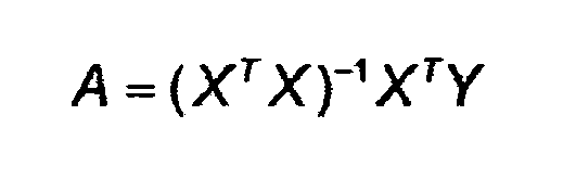
La matrice X est la matrice contenant pour chacune des arythmies la valeur des trois descripteurs en colonnes, et une quatrième colonne de 1. Cette matrice a la structure suivante, en supposant que l'on dispose d'une base de données de patients avec de 1 à N arythmies : 
La matrice Y est le vecteur constitué de -1 lorsque le point correspond à une TSV, et de 1 si le point correspond à une TV.The matrix Y is the vector consisting of -1 when the point corresponds to a TSV, and of 1 if the point corresponds to a TV.
Soit O la matrice qui contient la nouvelle valeur des descripteurs en colonnes, et une quatrième colonne de 1 pour classifier une arythmie, et soit z=A t O.Let O be the matrix that contains the new value of the descriptors in columns, and a fourth column of 1 to classify an arrhythmia, and let z = A t O.
Si z est négatif l'arythmie est classée en TSV, si z est positif l'arythmie est classée en TV.If z is negative the arrhythmia is classified in TSV, if z is positive the arrhythmia is classified in TV.
En variante, dans un souci de simplification des calculs et d'allègement de la charge de travail du processeur, il est possible d'appliquer la majeure partie des principes décrits dans ce qui précède sans recourir à l'analyse en composantes principales. Ainsi, les rapports R1,SR et R2,SR, respectivement entre l'amplitude maximale et l'amplitude minimale du complexe de dépolarisation sur les axes BipV et UnipV à partir de l'EGM en rythme sinusal du patient, ainsi que les rapports R1,TR et R2,TR pour les battements en tachycardie peuvent être déterminés sans recourir à l'analyse en composantes principales. De la même manière peuvent être déterminés les maxima de corrélation M1 et M2 entre les tracés du battement sinusal et du battement en tachycardie, respectivement sur les axes BipV et UnipV. Sur la base des valeurs ainsi déterminées, il est alors possible de déduire les valeurs D4 et D5, pour poursuivre l'analyse sur la base de ces descripteurs, selon la description fournie dans les paragraphes précédents.As a variant, for the sake of simplifying the calculations and lightening the processor workload, it is possible to apply the majority of the principles described in the foregoing without resorting to the principal component analysis. Thus, the ratios R 1, SR and R 2, SR respectively between the maximum amplitude and the minimum amplitude of the depolarization complex on the BipV and UnipV axes from the patient's sinus rhythm EGM, as well as the ratios R 1, TR and R 2, TR for tachycardia beats can be determined without the use of principal components analysis. Similarly, the correlation maxima M 1 and M 2 can be determined between the sinus beat and the tachycardia beat plots, respectively on the BipV and UnipV axes. On the basis of the values thus determined, it is then possible to deduce the values D4 and D5, to continue the analysis on the basis of these descriptors, according to the description provided in the preceding paragraphs.
La base de données est évolutive et se complète en continu dans le dispositif, chaque arythmie venant soit s'ajouter soit prendre la place d'une arythmie de la base de données. Par ailleurs, le dispositif, implant ou programmateur, recalcule à intervalles réguliers la matrice A.The database is scalable and continuously complete in the device, each arrhythmia to be added or replace the arrhythmia of the database. Moreover, the device, implant or programmer recalculates the matrix A at regular intervals.
Le dispositif peut comporter des moyens complémentaires pour vérifier a posteriori la classification de l'arythmie, par exemple :
- si le dispositif détecte une TV par la méthode de la classification linéaire, il en avertit le patient par un signal sonore. Si la TV disparaît, la classification était erronée ;
- si le dispositif détecte une TSV qui se transforme en fibrillation ventriculaire, la classification était erronée ;
- si le dispositif fait une erreur de classification d'une arythmie, un enregistrement d'ECG tel un Holter permet de la détecter, le médecin l'indique par télémétrie au défibrillateur ;
- etc.
- if the device detects a TV by the linear classification method, it warns the patient by an audible signal. If the TV disappears, the classification was wrong;
- if the device detects a TSV that is transformed into ventricular fibrillation, the classification was erroneous;
- if the device makes a mistake in classifying an arrhythmia, an ECG recording such as a Holter can detect it, the doctor indicates it by telemetry to the defibrillator;
- etc.
Le dispositif ayant ainsi avéré une erreur de classification d'une arythmie peut :
- soit ajouter l'arythmie à la base de données,
- soit remplacer une arythmie du même type dans la base de données puis recalculer la matrice A.
- add the arrhythmia to the database,
- either replace an arrhythmia of the same type in the database and then recalculate the matrix A.
Une autre forme de réalisation peut, en variante, mettre en oeuvre un classifieur neuronal, ce qui permet notamment d'opérer au moyen d'un réseau adaptatif, au lieu d'un calcul purement mathématique.Another embodiment may, alternatively, implement a neural classifier, which allows in particular to operate by means of an adaptive network, instead of a purely mathematical calculation.
Ce classifieur est construit dans l'espace 3D formé par exemple par les trois descripteurs EQM, M1 et D1 (cette méthode pouvant s'appliquer à d'autres descripteurs).This classifier is constructed in the 3D space formed for example by the three descriptors EQM, M 1 and D 1 (this method can be applied to other descriptors).
Un tel classifieur est caractérisé par l'équation du plan séparant dans cet espace les deux familles d'arythmies, TV et TSV. Soit : ![]()
![]()
![]()
- W étant le vecteur constitué de poids appliqués à chaque descripteur ;
- Φ étant le vecteur contenant pour une arythmie en colonnes la valeur des trois descripteurs et le biais 1 (EQM, M1, D1, 1) ;
- y étant le prédicteur : si y est négatif l'arythmie est classée en TSV, si y est positif l'arythmie est classée en TV.
- W being the vector consisting of weights applied to each descriptor;
- Φ being the vector containing for an arrhythmia in columns the value of the three descriptors and the bias 1 ( EQM, M1, D1, 1);
- y being the predictor: if there is negative arrhythmia is classified TSV, if there is positive arrhythmia is classified TV.
La valeur de W est déterminée par l'algorithme du gradient déterministe en appliquant la règle suivante :
- · W est initialisé ;
- · on fait l'apprentissage sur un ensemble d'arythmies préalablement classifiées et confirmées :
- · si la prédiction est bonne W n'est pas modifié
- · si pour une tachycardie supraventriculaire Φ n la prédiction est mauvaise, on soustrait à W la valeur de Φn ;
- · si pour une tachycardie ventriculaire Φ m la prédiction est mauvaise, on additionne à W la valeur Φ m .
- · W is initialized;
- · Learning is done on a set of arrhythmias previously classified and confirmed:
- · If the prediction is good W is not modified
- · If for supraventricular tachycardia Φ n the prediction is bad, subtract the value of Φ n from W ;
- If for ventricular tachycardia la m the prediction is bad, we add to W the value Φ m .
La base de données est évolutive et se complète en continu dans le dispositif, chaque arythmie venant soit s'ajouter soit prendre la place d'une arythmie de la base de données. Par ailleurs, le dispositif, implant ou programmateur, refait à intervalle régulier l'apprentissage de W.The database is scalable and continuously complete in the device, each arrhythmia to be added or replace the arrhythmia of the database. Moreover, the device, implant or programmer remakes at regular intervals the training of W.
Ici encore, le dispositif peut comporter de moyens complémentaires pour vérifier a posteriori la classification de l'arythmie, du même type que celles exposes plus haut, conduisant à un nouvel apprentissage de W à intervalles réguliers en cas d'erreurs de classification.Here again, the device may comprise complementary means for checking a posteriori classification arrhythmia, the same type as those discussed above, leading to a new learning of W at regular intervals in the event of misclassification.
Claims (29)
Applications Claiming Priority (1)
| Application Number | Priority Date | Filing Date | Title |
|---|---|---|---|
| FR0801691 | 2008-03-28 |
Publications (2)
| Publication Number | Publication Date |
|---|---|
| EP2105843A1 true EP2105843A1 (en) | 2009-09-30 |
| EP2105843B1 EP2105843B1 (en) | 2011-03-16 |
Family
ID=39679351
Family Applications (1)
| Application Number | Title | Priority Date | Filing Date |
|---|---|---|---|
| EP09290016A Active EP2105843B1 (en) | 2008-03-28 | 2009-01-09 | Active medical device comprising perfected means for distinguishing between tachycardia with ventricular causes and tachycardia with supraventricular causes |
Country Status (4)
| Country | Link |
|---|---|
| US (1) | US8195281B2 (en) |
| EP (1) | EP2105843B1 (en) |
| AT (1) | ATE502339T1 (en) |
| DE (1) | DE602009000871D1 (en) |
Cited By (8)
| Publication number | Priority date | Publication date | Assignee | Title |
|---|---|---|---|---|
| EP2324885A1 (en) | 2009-11-18 | 2011-05-25 | Sorin CRM SAS | Active medical device including means for capture testing through cardiac vectogram analysis |
| EP2332462A1 (en) * | 2009-12-11 | 2011-06-15 | Sorin CRM SAS | Single-chamber implantable cardioverter/defibrillator with detection of atrial activity via the single-body probe |
| FR2957512A1 (en) * | 2010-03-22 | 2011-09-23 | Sorin Crm Sas | ACTIVE MEDICAL DEVICE COMPRISING MEANS FOR DETECTING AND FILTERING ARTIFACTS BY ANALYZING THE HEART VECTOGRAM |
| EP2742973A1 (en) | 2012-12-14 | 2014-06-18 | Sorin CRM SAS | Active implantable medical device such as a pacemaker with anodal stimulation detection by vector cardiogram analysis |
| EP3075413A1 (en) | 2015-04-02 | 2016-10-05 | Sorin CRM SAS | Implantable medical device for biventricular stimulation, including means for measuring intraventricular conduction time for diagnosis of heart decompensation |
| EP3081257A1 (en) | 2015-04-17 | 2016-10-19 | Sorin CRM SAS | Active implantable medical device for cardiac stimulation comprising means for detecting a remodelling or reverse remodelling phenomenon of the patient |
| EP3760114A1 (en) | 2019-07-05 | 2021-01-06 | Sorin CRM SAS | Subcutaneous implantable medical device and method for processing signals from a subcutaneous implantable medical device |
| EP2412401B1 (en) * | 2010-07-26 | 2022-01-05 | Sorin CRM SAS | Active implantable medical device with means for testing ventricular capture by analysing an endocardiac acceleration signal |
Families Citing this family (8)
| Publication number | Priority date | Publication date | Assignee | Title |
|---|---|---|---|---|
| US8903490B2 (en) * | 2010-03-03 | 2014-12-02 | Cardiac Pacemakers, Inc. | Methods and systems for recognizing arrhythmias using neural stimulation |
| US10517494B2 (en) * | 2014-11-14 | 2019-12-31 | Beth Israel Deaconess Medical Center, Inc. | Method and system to access inapparent conduction abnormalities to identify risk of ventricular tachycardia |
| US9675270B2 (en) | 2015-04-23 | 2017-06-13 | Medtronic, Inc. | Method and apparatus for determining a premature ventricular contraction in a medical monitoring device |
| US10973429B2 (en) | 2018-01-23 | 2021-04-13 | Chelak Iecg, Inc. | Precise localization of cardiac arrhythmia using internal electrocardiograph (ECG) signals sensed and stored by implantable device |
| US11154233B2 (en) | 2018-06-21 | 2021-10-26 | Mayo Foundation For Medical Education And Research | Apparatus and method for differentiating wide complex heart beats |
| WO2020014715A2 (en) * | 2018-06-21 | 2020-01-16 | Mayo Foundation For Medical Education And Research | Apparatus and method for distinguishing wide complex heart beats |
| CN113164753B (en) * | 2019-01-23 | 2023-03-24 | 脉冲动力(北京)医疗科技有限公司 | Differentiation of supraventricular tachycardia in a combined cardiac contractility modulation-implantable cardioverter defibrillator device |
| CN111714771B (en) * | 2019-12-16 | 2023-12-29 | 苏州无双医疗设备有限公司 | Implantable medical device with ventricular rate diagnostic function |
Citations (9)
| Publication number | Priority date | Publication date | Assignee | Title |
|---|---|---|---|---|
| EP0626182A1 (en) | 1993-05-28 | 1994-11-30 | ELA MEDICAL (Société anonyme) | Method of analysis of the cardiac activity for determining whether or not a tachyarrythmia may be interrupted by stimulation |
| EP0813888A1 (en) | 1996-06-18 | 1997-12-29 | ELA MEDICAL (Société anonyme) | Defibrillator/cardioverter type active medical device with improved discrimination of tachycardia |
| EP0838235A1 (en) | 1996-10-25 | 1998-04-29 | ELA MEDICAL (Société anonyme) | Defibrillator/cardioverter type active medical device with improved discrimination of tachycardia |
| WO2000069517A1 (en) | 1999-05-12 | 2000-11-23 | Medtronic, Inc. | Monitoring apparatus using wavelet transforms for the analysis of heart rhythms |
| EP1208873A1 (en) | 2000-11-27 | 2002-05-29 | Ela Medical | Active medical device of the implantable defibrillator/cardioverter type with improved atrial fibrillation discrimination |
| US20030083587A1 (en) * | 2001-10-31 | 2003-05-01 | Bozidar Ferek-Petric | Method and apparatus for developing a vectorcardiograph in an implantable medical devicee |
| US20050159781A1 (en) | 1999-07-14 | 2005-07-21 | Cardiac Pacemakers, Inc. | Classification of supraventricular and ventricular cardiac rhythms using cross channel timing algorithm |
| WO2006039693A1 (en) * | 2004-09-30 | 2006-04-13 | Cardiac Pacemakers, Inc. | Cardiac activation sequence monitoring and tracking |
| US7149569B1 (en) | 2003-12-15 | 2006-12-12 | Pacesetter, Inc. | Apparatus and method for improved morphology discrimination in an implantable cardioverter defibrillator |
Family Cites Families (4)
| Publication number | Priority date | Publication date | Assignee | Title |
|---|---|---|---|---|
| US5766131A (en) * | 1995-08-04 | 1998-06-16 | Seiko Epson Corporation | Pulse-wave measuring apparatus |
| US7457664B2 (en) | 2005-05-09 | 2008-11-25 | Cardiac Pacemakers, Inc. | Closed loop cardiac resynchronization therapy using cardiac activation sequence information |
| FR2906123A1 (en) | 2006-09-25 | 2008-03-28 | Ela Medical Soc Par Actions Si | METHOD FOR RECONSTRUCTING A SURFACE ELECTROCARDIOGRAM FROM A ENDOCAVITARY ELECTROGRAM |
| US7751873B2 (en) * | 2006-11-08 | 2010-07-06 | Biotronik Crm Patent Ag | Wavelet based feature extraction and dimension reduction for the classification of human cardiac electrogram depolarization waveforms |
-
2009
- 2009-01-09 EP EP09290016A patent/EP2105843B1/en active Active
- 2009-01-09 AT AT09290016T patent/ATE502339T1/en not_active IP Right Cessation
- 2009-01-09 DE DE602009000871T patent/DE602009000871D1/en active Active
- 2009-03-27 US US12/412,808 patent/US8195281B2/en active Active
Patent Citations (9)
| Publication number | Priority date | Publication date | Assignee | Title |
|---|---|---|---|---|
| EP0626182A1 (en) | 1993-05-28 | 1994-11-30 | ELA MEDICAL (Société anonyme) | Method of analysis of the cardiac activity for determining whether or not a tachyarrythmia may be interrupted by stimulation |
| EP0813888A1 (en) | 1996-06-18 | 1997-12-29 | ELA MEDICAL (Société anonyme) | Defibrillator/cardioverter type active medical device with improved discrimination of tachycardia |
| EP0838235A1 (en) | 1996-10-25 | 1998-04-29 | ELA MEDICAL (Société anonyme) | Defibrillator/cardioverter type active medical device with improved discrimination of tachycardia |
| WO2000069517A1 (en) | 1999-05-12 | 2000-11-23 | Medtronic, Inc. | Monitoring apparatus using wavelet transforms for the analysis of heart rhythms |
| US20050159781A1 (en) | 1999-07-14 | 2005-07-21 | Cardiac Pacemakers, Inc. | Classification of supraventricular and ventricular cardiac rhythms using cross channel timing algorithm |
| EP1208873A1 (en) | 2000-11-27 | 2002-05-29 | Ela Medical | Active medical device of the implantable defibrillator/cardioverter type with improved atrial fibrillation discrimination |
| US20030083587A1 (en) * | 2001-10-31 | 2003-05-01 | Bozidar Ferek-Petric | Method and apparatus for developing a vectorcardiograph in an implantable medical devicee |
| US7149569B1 (en) | 2003-12-15 | 2006-12-12 | Pacesetter, Inc. | Apparatus and method for improved morphology discrimination in an implantable cardioverter defibrillator |
| WO2006039693A1 (en) * | 2004-09-30 | 2006-04-13 | Cardiac Pacemakers, Inc. | Cardiac activation sequence monitoring and tracking |
Cited By (22)
| Publication number | Priority date | Publication date | Assignee | Title |
|---|---|---|---|---|
| US9014806B2 (en) | 2009-11-18 | 2015-04-21 | Sorin Crm Sas | System and method for performing a capture test based on the analysis of a cardiac vectogram |
| EP2324885A1 (en) | 2009-11-18 | 2011-05-25 | Sorin CRM SAS | Active medical device including means for capture testing through cardiac vectogram analysis |
| EP2332462A1 (en) * | 2009-12-11 | 2011-06-15 | Sorin CRM SAS | Single-chamber implantable cardioverter/defibrillator with detection of atrial activity via the single-body probe |
| US9446256B2 (en) | 2009-12-11 | 2016-09-20 | Sorin Crm S.A.S. | Atrial activity signal estimation using independent component analysis |
| FR2957512A1 (en) * | 2010-03-22 | 2011-09-23 | Sorin Crm Sas | ACTIVE MEDICAL DEVICE COMPRISING MEANS FOR DETECTING AND FILTERING ARTIFACTS BY ANALYZING THE HEART VECTOGRAM |
| EP2368493A1 (en) | 2010-03-22 | 2011-09-28 | Sorin CRM SAS | Active medical device including means for detecting and filtering artefacts by cardiac vector diagram analysis |
| US8359091B2 (en) | 2010-03-22 | 2013-01-22 | Sorin Crm S.A.S. | Apparatus and method for detecting and filtering artifacts by analysis of a cardiac vectogram |
| EP2412401B1 (en) * | 2010-07-26 | 2022-01-05 | Sorin CRM SAS | Active implantable medical device with means for testing ventricular capture by analysing an endocardiac acceleration signal |
| EP2742973A1 (en) | 2012-12-14 | 2014-06-18 | Sorin CRM SAS | Active implantable medical device such as a pacemaker with anodal stimulation detection by vector cardiogram analysis |
| FR2999440A1 (en) * | 2012-12-14 | 2014-06-20 | Sorin Crm Sas | ACTIVE IMPLANTABLE MEDICAL DEVICE OF CARDIAC STIMULATOR TYPE HAVING ANODIC STIMULATION DETECTION BY VECTOGRAM ANALYSIS |
| US8874212B2 (en) | 2012-12-14 | 2014-10-28 | Sorin Crm S.A.S. | Active implantable medical device type such as a pacemaker with detection of anodal stimulation by analysis of a vectogram |
| EP3075413A1 (en) | 2015-04-02 | 2016-10-05 | Sorin CRM SAS | Implantable medical device for biventricular stimulation, including means for measuring intraventricular conduction time for diagnosis of heart decompensation |
| US9757568B2 (en) | 2015-04-02 | 2017-09-12 | Sorin Crm Sas | Active implantable medical device for the diagnosis of cardiac decompensation |
| US10022547B2 (en) | 2015-04-02 | 2018-07-17 | Sorin Crm Sas | Active implantable medical device for the diagnosis of cardiac decompensation |
| US10328269B2 (en) | 2015-04-02 | 2019-06-25 | Sorin Crm Sas | Active implantable medical device for the diagnosis of cardiac decompensation |
| US11058881B2 (en) | 2015-04-02 | 2021-07-13 | Sorin Crm Sas | Active implantable medical device for the diagnosis of cardiac decompensation |
| FR3034319A1 (en) * | 2015-04-02 | 2016-10-07 | Sorin Crm Sas | ACTIVE IMPLANTABLE MEDICAL DEVICE WITH BIVENTRICULAR STIMULATION, COMPRISING MEANS FOR MEASURING INTERVENTRICULAR CONDUCTION TIME FOR DIAGNOSING CARDIAC DECOMPENSATION. |
| EP3081257A1 (en) | 2015-04-17 | 2016-10-19 | Sorin CRM SAS | Active implantable medical device for cardiac stimulation comprising means for detecting a remodelling or reverse remodelling phenomenon of the patient |
| US9757566B2 (en) | 2015-04-17 | 2017-09-12 | Sorin Crm Sas | Active implantable medical device for detecting a remodeling or reverse remodeling phenomenon of the patient |
| US10420945B2 (en) | 2015-04-17 | 2019-09-24 | Sorin Crm Sas | Active implantable medical device for detecting a remodeling or reverse remodeling phenomenon of the patient |
| US11198009B2 (en) | 2015-04-17 | 2021-12-14 | Sorin Crm Sas | Active implantable medical device for detecting a remodeling or reverse remodeling phenomenon of the patient |
| EP3760114A1 (en) | 2019-07-05 | 2021-01-06 | Sorin CRM SAS | Subcutaneous implantable medical device and method for processing signals from a subcutaneous implantable medical device |
Also Published As
| Publication number | Publication date |
|---|---|
| US8195281B2 (en) | 2012-06-05 |
| DE602009000871D1 (en) | 2011-04-28 |
| ATE502339T1 (en) | 2011-04-15 |
| US20100249626A1 (en) | 2010-09-30 |
| EP2105843B1 (en) | 2011-03-16 |
Similar Documents
| Publication | Publication Date | Title |
|---|---|---|
| EP2105843B1 (en) | Active medical device comprising perfected means for distinguishing between tachycardia with ventricular causes and tachycardia with supraventricular causes | |
| EP2070562B1 (en) | Medical device for characterising the cardiac condition of a patient fitted with an active implant for biventricular stimulation | |
| EP1867360B1 (en) | Active implantable medical device, in particular a stimulation, resynchronisation, defibrillation and/or cardioversion device comprising predictive means for warning of an aggravation of the patient's clinical status | |
| EP2412401B1 (en) | Active implantable medical device with means for testing ventricular capture by analysing an endocardiac acceleration signal | |
| EP2263747B1 (en) | Implantable cardiac prosthesis comprising means for analysing patient's tolerance of stimulation mode aiming at spontaneous atrio-ventricular conduction | |
| EP2324885B1 (en) | Active medical device including means for capture testing through cardiac vectogram analysis | |
| EP1902750B1 (en) | Method of reconstructing a surface electrocardiogram from an intracardiac electrogram | |
| EP2052680B1 (en) | Electrocardiology diagnosis assistance device, in particular for diagnosing Brugada syndrome and ERS | |
| EP2368493B1 (en) | Active medical device including means for detecting and filtering artefacts by cardiac vector diagram analysis | |
| EP2499971B1 (en) | Device for adaptive processing of an endocardial acceleration signal | |
| EP2623023B1 (en) | Active implantable medical device including a means for diagnosing heart failure | |
| EP1419733A1 (en) | Device for analysis of a signal, in particular a physiological signal such as an ECG signal | |
| EP2357020A1 (en) | Active medical device of the pacemaker, defibrillator or resynchronizer type, with automatic atrioventricular delay optimisation | |
| EP1405654B1 (en) | Active implantable medical devices, such as defibrillators, cardioverters and/or multisite devices, comprising means for determining the average hemodynamic index | |
| EP3669773B1 (en) | Device and method for detecting ventricular fibrillation | |
| EP2742973A1 (en) | Active implantable medical device such as a pacemaker with anodal stimulation detection by vector cardiogram analysis | |
| EP3081257B1 (en) | Active implantable medical device for cardiac stimulation comprising means for detecting a remodelling or reverse remodelling phenomenon of the patient | |
| EP2684515B1 (en) | Active medical device comprising means for monitoring the condition of a patient suffering from a risk of heart failure | |
| EP1366428A2 (en) | Method and device for filtering a series of cardiac rhythm signals (rr) derived from a cardiac signal, and more particularly an ecg signal | |
| EP2839859A1 (en) | Active medical device, in particular a CRT resynchroniser, including predictive warning means for cardiac decompensation in the presence of central sleep apnoea | |
| EP3165160B1 (en) | Active implantable medical device comprising means for detecting and quantifying fusion situations | |
| EP3075413B1 (en) | Implantable medical device for biventricular stimulation, including means for measuring intraventricular conduction time for diagnosis of heart decompensation | |
| EP3760114B1 (en) | Subcutaneous implantable medical device for processing signals from a subcutaneous implantable medical device | |
| WO2017121702A1 (en) | Active implantable medical defibrillation device, including improved means for discriminating between external noise and probe breakage and for characterising tachyarrhythmias | |
| EP2332462A1 (en) | Single-chamber implantable cardioverter/defibrillator with detection of atrial activity via the single-body probe |
Legal Events
| Date | Code | Title | Description |
|---|---|---|---|
| PUAI | Public reference made under article 153(3) epc to a published international application that has entered the european phase |
Free format text: ORIGINAL CODE: 0009012 |
|
| AK | Designated contracting states |
Kind code of ref document: A1 Designated state(s): AT BE BG CH CY CZ DE DK EE ES FI FR GB GR HR HU IE IS IT LI LT LU LV MC MK MT NL NO PL PT RO SE SI SK TR |
|
| AX | Request for extension of the european patent |
Extension state: AL BA RS |
|
| 17P | Request for examination filed |
Effective date: 20091028 |
|
| 17Q | First examination report despatched |
Effective date: 20091124 |
|
| AKX | Designation fees paid |
Designated state(s): AT BE BG CH CY CZ DE DK EE ES FI FR GB GR HR HU IE IS IT LI LT LU LV MC MK MT NL NO PL PT RO SE SI SK TR |
|
| GRAP | Despatch of communication of intention to grant a patent |
Free format text: ORIGINAL CODE: EPIDOSNIGR1 |
|
| GRAS | Grant fee paid |
Free format text: ORIGINAL CODE: EPIDOSNIGR3 |
|
| GRAA | (expected) grant |
Free format text: ORIGINAL CODE: 0009210 |
|
| AK | Designated contracting states |
Kind code of ref document: B1 Designated state(s): AT BE BG CH CY CZ DE DK EE ES FI FR GB GR HR HU IE IS IT LI LT LU LV MC MK MT NL NO PL PT RO SE SI SK TR |
|
| REG | Reference to a national code |
Ref country code: GB Ref legal event code: FG4D Free format text: NOT ENGLISH |
|
| REG | Reference to a national code |
Ref country code: CH Ref legal event code: EP |
|
| REG | Reference to a national code |
Ref country code: IE Ref legal event code: FG4D |
|
| REF | Corresponds to: |
Ref document number: 602009000871 Country of ref document: DE Date of ref document: 20110428 Kind code of ref document: P |
|
| REG | Reference to a national code |
Ref country code: DE Ref legal event code: R096 Ref document number: 602009000871 Country of ref document: DE Effective date: 20110428 |
|
| REG | Reference to a national code |
Ref country code: SE Ref legal event code: TRGR |
|
| REG | Reference to a national code |
Ref country code: NL Ref legal event code: VDEP Effective date: 20110316 |
|
| PG25 | Lapsed in a contracting state [announced via postgrant information from national office to epo] |
Ref country code: LV Free format text: LAPSE BECAUSE OF FAILURE TO SUBMIT A TRANSLATION OF THE DESCRIPTION OR TO PAY THE FEE WITHIN THE PRESCRIBED TIME-LIMIT Effective date: 20110316 Ref country code: ES Free format text: LAPSE BECAUSE OF FAILURE TO SUBMIT A TRANSLATION OF THE DESCRIPTION OR TO PAY THE FEE WITHIN THE PRESCRIBED TIME-LIMIT Effective date: 20110627 Ref country code: NO Free format text: LAPSE BECAUSE OF FAILURE TO SUBMIT A TRANSLATION OF THE DESCRIPTION OR TO PAY THE FEE WITHIN THE PRESCRIBED TIME-LIMIT Effective date: 20110616 Ref country code: GR Free format text: LAPSE BECAUSE OF FAILURE TO SUBMIT A TRANSLATION OF THE DESCRIPTION OR TO PAY THE FEE WITHIN THE PRESCRIBED TIME-LIMIT Effective date: 20110617 Ref country code: LT Free format text: LAPSE BECAUSE OF FAILURE TO SUBMIT A TRANSLATION OF THE DESCRIPTION OR TO PAY THE FEE WITHIN THE PRESCRIBED TIME-LIMIT Effective date: 20110316 Ref country code: HR Free format text: LAPSE BECAUSE OF FAILURE TO SUBMIT A TRANSLATION OF THE DESCRIPTION OR TO PAY THE FEE WITHIN THE PRESCRIBED TIME-LIMIT Effective date: 20110316 |
|
| LTIE | Lt: invalidation of european patent or patent extension |
Effective date: 20110316 |
|
| PG25 | Lapsed in a contracting state [announced via postgrant information from national office to epo] |
Ref country code: BG Free format text: LAPSE BECAUSE OF FAILURE TO SUBMIT A TRANSLATION OF THE DESCRIPTION OR TO PAY THE FEE WITHIN THE PRESCRIBED TIME-LIMIT Effective date: 20110616 Ref country code: AT Free format text: LAPSE BECAUSE OF FAILURE TO SUBMIT A TRANSLATION OF THE DESCRIPTION OR TO PAY THE FEE WITHIN THE PRESCRIBED TIME-LIMIT Effective date: 20110316 Ref country code: CY Free format text: LAPSE BECAUSE OF FAILURE TO SUBMIT A TRANSLATION OF THE DESCRIPTION OR TO PAY THE FEE WITHIN THE PRESCRIBED TIME-LIMIT Effective date: 20110316 Ref country code: FI Free format text: LAPSE BECAUSE OF FAILURE TO SUBMIT A TRANSLATION OF THE DESCRIPTION OR TO PAY THE FEE WITHIN THE PRESCRIBED TIME-LIMIT Effective date: 20110316 Ref country code: SI Free format text: LAPSE BECAUSE OF FAILURE TO SUBMIT A TRANSLATION OF THE DESCRIPTION OR TO PAY THE FEE WITHIN THE PRESCRIBED TIME-LIMIT Effective date: 20110316 |
|
| PG25 | Lapsed in a contracting state [announced via postgrant information from national office to epo] |
Ref country code: EE Free format text: LAPSE BECAUSE OF FAILURE TO SUBMIT A TRANSLATION OF THE DESCRIPTION OR TO PAY THE FEE WITHIN THE PRESCRIBED TIME-LIMIT Effective date: 20110316 Ref country code: PT Free format text: LAPSE BECAUSE OF FAILURE TO SUBMIT A TRANSLATION OF THE DESCRIPTION OR TO PAY THE FEE WITHIN THE PRESCRIBED TIME-LIMIT Effective date: 20110718 |
|
| PG25 | Lapsed in a contracting state [announced via postgrant information from national office to epo] |
Ref country code: CZ Free format text: LAPSE BECAUSE OF FAILURE TO SUBMIT A TRANSLATION OF THE DESCRIPTION OR TO PAY THE FEE WITHIN THE PRESCRIBED TIME-LIMIT Effective date: 20110316 Ref country code: IS Free format text: LAPSE BECAUSE OF FAILURE TO SUBMIT A TRANSLATION OF THE DESCRIPTION OR TO PAY THE FEE WITHIN THE PRESCRIBED TIME-LIMIT Effective date: 20110716 Ref country code: RO Free format text: LAPSE BECAUSE OF FAILURE TO SUBMIT A TRANSLATION OF THE DESCRIPTION OR TO PAY THE FEE WITHIN THE PRESCRIBED TIME-LIMIT Effective date: 20110316 Ref country code: SK Free format text: LAPSE BECAUSE OF FAILURE TO SUBMIT A TRANSLATION OF THE DESCRIPTION OR TO PAY THE FEE WITHIN THE PRESCRIBED TIME-LIMIT Effective date: 20110316 |
|
| PG25 | Lapsed in a contracting state [announced via postgrant information from national office to epo] |
Ref country code: NL Free format text: LAPSE BECAUSE OF FAILURE TO SUBMIT A TRANSLATION OF THE DESCRIPTION OR TO PAY THE FEE WITHIN THE PRESCRIBED TIME-LIMIT Effective date: 20110316 |
|
| PLBE | No opposition filed within time limit |
Free format text: ORIGINAL CODE: 0009261 |
|
| STAA | Information on the status of an ep patent application or granted ep patent |
Free format text: STATUS: NO OPPOSITION FILED WITHIN TIME LIMIT |
|
| 26N | No opposition filed |
Effective date: 20111219 |
|
| PG25 | Lapsed in a contracting state [announced via postgrant information from national office to epo] |
Ref country code: PL Free format text: LAPSE BECAUSE OF FAILURE TO SUBMIT A TRANSLATION OF THE DESCRIPTION OR TO PAY THE FEE WITHIN THE PRESCRIBED TIME-LIMIT Effective date: 20110316 |
|
| REG | Reference to a national code |
Ref country code: DE Ref legal event code: R097 Ref document number: 602009000871 Country of ref document: DE Effective date: 20111219 |
|
| PGFP | Annual fee paid to national office [announced via postgrant information from national office to epo] |
Ref country code: SE Payment date: 20120112 Year of fee payment: 4 |
|
| BERE | Be: lapsed |
Owner name: ELA MEDICAL Effective date: 20120131 |
|
| PG25 | Lapsed in a contracting state [announced via postgrant information from national office to epo] |
Ref country code: MC Free format text: LAPSE BECAUSE OF NON-PAYMENT OF DUE FEES Effective date: 20120131 |
|
| PG25 | Lapsed in a contracting state [announced via postgrant information from national office to epo] |
Ref country code: BE Free format text: LAPSE BECAUSE OF NON-PAYMENT OF DUE FEES Effective date: 20120131 |
|
| PG25 | Lapsed in a contracting state [announced via postgrant information from national office to epo] |
Ref country code: MK Free format text: LAPSE BECAUSE OF FAILURE TO SUBMIT A TRANSLATION OF THE DESCRIPTION OR TO PAY THE FEE WITHIN THE PRESCRIBED TIME-LIMIT Effective date: 20110316 |
|
| PGFP | Annual fee paid to national office [announced via postgrant information from national office to epo] |
Ref country code: IE Payment date: 20130110 Year of fee payment: 5 |
|
| PG25 | Lapsed in a contracting state [announced via postgrant information from national office to epo] |
Ref country code: MT Free format text: LAPSE BECAUSE OF FAILURE TO SUBMIT A TRANSLATION OF THE DESCRIPTION OR TO PAY THE FEE WITHIN THE PRESCRIBED TIME-LIMIT Effective date: 20110316 |
|
| REG | Reference to a national code |
Ref country code: CH Ref legal event code: PL |
|
| REG | Reference to a national code |
Ref country code: SE Ref legal event code: EUG |
|
| PG25 | Lapsed in a contracting state [announced via postgrant information from national office to epo] |
Ref country code: CH Free format text: LAPSE BECAUSE OF NON-PAYMENT OF DUE FEES Effective date: 20130131 Ref country code: LI Free format text: LAPSE BECAUSE OF NON-PAYMENT OF DUE FEES Effective date: 20130131 Ref country code: SE Free format text: LAPSE BECAUSE OF NON-PAYMENT OF DUE FEES Effective date: 20130110 |
|
| PG25 | Lapsed in a contracting state [announced via postgrant information from national office to epo] |
Ref country code: TR Free format text: LAPSE BECAUSE OF FAILURE TO SUBMIT A TRANSLATION OF THE DESCRIPTION OR TO PAY THE FEE WITHIN THE PRESCRIBED TIME-LIMIT Effective date: 20110316 |
|
| PG25 | Lapsed in a contracting state [announced via postgrant information from national office to epo] |
Ref country code: LU Free format text: LAPSE BECAUSE OF NON-PAYMENT OF DUE FEES Effective date: 20120109 |
|
| PG25 | Lapsed in a contracting state [announced via postgrant information from national office to epo] |
Ref country code: HU Free format text: LAPSE BECAUSE OF FAILURE TO SUBMIT A TRANSLATION OF THE DESCRIPTION OR TO PAY THE FEE WITHIN THE PRESCRIBED TIME-LIMIT Effective date: 20090109 |
|
| REG | Reference to a national code |
Ref country code: IE Ref legal event code: MM4A |
|
| PG25 | Lapsed in a contracting state [announced via postgrant information from national office to epo] |
Ref country code: IE Free format text: LAPSE BECAUSE OF NON-PAYMENT OF DUE FEES Effective date: 20140109 |
|
| REG | Reference to a national code |
Ref country code: FR Ref legal event code: PLFP Year of fee payment: 8 |
|
| REG | Reference to a national code |
Ref country code: FR Ref legal event code: PLFP Year of fee payment: 9 |
|
| REG | Reference to a national code |
Ref country code: FR Ref legal event code: PLFP Year of fee payment: 10 |
|
| PGFP | Annual fee paid to national office [announced via postgrant information from national office to epo] |
Ref country code: FR Payment date: 20230125 Year of fee payment: 15 |
|
| PGFP | Annual fee paid to national office [announced via postgrant information from national office to epo] |
Ref country code: IT Payment date: 20230110 Year of fee payment: 15 Ref country code: DE Payment date: 20230112 Year of fee payment: 15 Ref country code: GB Payment date: 20230123 Year of fee payment: 15 |
|
| P01 | Opt-out of the competence of the unified patent court (upc) registered |
Effective date: 20230714 |