EP2106742A1 - Ophthalmologic photographing apparatus - Google Patents
Ophthalmologic photographing apparatus Download PDFInfo
- Publication number
- EP2106742A1 EP2106742A1 EP09157225A EP09157225A EP2106742A1 EP 2106742 A1 EP2106742 A1 EP 2106742A1 EP 09157225 A EP09157225 A EP 09157225A EP 09157225 A EP09157225 A EP 09157225A EP 2106742 A1 EP2106742 A1 EP 2106742A1
- Authority
- EP
- European Patent Office
- Prior art keywords
- light
- eye
- control unit
- amount
- subject
- Prior art date
- Legal status (The legal status is an assumption and is not a legal conclusion. Google has not performed a legal analysis and makes no representation as to the accuracy of the status listed.)
- Withdrawn
Links
Images


Classifications
-
- A—HUMAN NECESSITIES
- A61—MEDICAL OR VETERINARY SCIENCE; HYGIENE
- A61B—DIAGNOSIS; SURGERY; IDENTIFICATION
- A61B3/00—Apparatus for testing the eyes; Instruments for examining the eyes
- A61B3/10—Objective types, i.e. instruments for examining the eyes independent of the patients' perceptions or reactions
- A61B3/11—Objective types, i.e. instruments for examining the eyes independent of the patients' perceptions or reactions for measuring interpupillary distance or diameter of pupils
- A61B3/112—Objective types, i.e. instruments for examining the eyes independent of the patients' perceptions or reactions for measuring interpupillary distance or diameter of pupils for measuring diameter of pupils
-
- A—HUMAN NECESSITIES
- A61—MEDICAL OR VETERINARY SCIENCE; HYGIENE
- A61B—DIAGNOSIS; SURGERY; IDENTIFICATION
- A61B3/00—Apparatus for testing the eyes; Instruments for examining the eyes
- A61B3/0016—Operational features thereof
- A61B3/0033—Operational features thereof characterised by user input arrangements
-
- A—HUMAN NECESSITIES
- A61—MEDICAL OR VETERINARY SCIENCE; HYGIENE
- A61B—DIAGNOSIS; SURGERY; IDENTIFICATION
- A61B3/00—Apparatus for testing the eyes; Instruments for examining the eyes
- A61B3/10—Objective types, i.e. instruments for examining the eyes independent of the patients' perceptions or reactions
- A61B3/12—Objective types, i.e. instruments for examining the eyes independent of the patients' perceptions or reactions for looking at the eye fundus, e.g. ophthalmoscopes
-
- A—HUMAN NECESSITIES
- A61—MEDICAL OR VETERINARY SCIENCE; HYGIENE
- A61B—DIAGNOSIS; SURGERY; IDENTIFICATION
- A61B3/00—Apparatus for testing the eyes; Instruments for examining the eyes
- A61B3/10—Objective types, i.e. instruments for examining the eyes independent of the patients' perceptions or reactions
- A61B3/14—Arrangements specially adapted for eye photography
Definitions
- the present invention relates to an ophthalmologic photographing apparatus used in photographing a fundus of a subject's eye at an ophthalmologic clinic.
- a mydriatic photographing method two types of photographing methods, i.e., a mydriatic photographing method and a non-mydriatic photographing method, have been known as methods for photographing fundus images.
- fundus photographing is performed by illuminating a fundus of a subject's eye with visible light at both of the time of observing the fundus of the subject's eye and the time of photographing thereof using a mydriatic.
- fundus photographing is performed without using a mydriatic by illuminating a fundus of a subject's eye with infrared light at the time of observing the fundus of the subject's eye, and illuminating the fundus of the subject' s eye with visible light at the time of photographing thereof.
- the mydriatic photographing method and the non-mydriatic photographing method have been respectively performed using different apparatuses.
- an apparatus capable of performing both of the mydriatic photographing method and the non-mydriatic photographing method has been proposed.
- Japanese Patent Application Laid-Open No. 9-140672 discusses a fundus camera in which an infrared filter is detachably arranged in an optical path extending from an illumination optical system, which illuminates a fundus of a subject' s eye to be photographed, to the fundus of the subject' s eye.
- An operator of this apparatus switches a mydriatic/non-mydriatic photographing mode selector switch of the fundus camera.
- the operator controls attachment/detachment of the infrared filter. Consequently, both of the mydriatic photographing method and the non-mydriatic photographing method can be performed using this single fundus camera.
- Japanese Patent Application Laid-Open No. 6-178762 discusses a perimeter for photographing a subject's eye using a photographing unit, such as a charge-coupled device (CCD), and for detecting a low-luminance portion on each scanning line while scanning photographed video signals, whereby a value of a pupil diameter can be detected based on a scanning time taken to scan the longest low-luminance portion among the low-luminance portions respectively detected on the scanning lines.
- a photographing unit such as a charge-coupled device (CCD)
- CCD charge-coupled device
- the fundus camera discussed in Japanese Patent Application Laid-Open No. 9-140672 is constructed so as to have the mydriatic/non-mydriatic photographing mode selector switch that an operator operates to select which of a mydriatic photographing mode and a non-mydriatic photographing mode is performed.
- the fundus of a subject's eye is illuminated with visible light when the subject's eye is observed.
- myosis of the subject' s eye is induced.
- a time required by the pupil diameter to exceed the minimum value due to natural mydriasis varies with environment and differences among individual subjects. Thus, such a time may be several minutes. In such a time, the fundus of the subject's eye cannot be photographed. Consequently, efficiency in photographing the fundus is lowered.
- Japanese Patent Application Laid-Open No. 6-178762 does not discuss a method for adding the measured pupil diameter to image information. Thus, it is necessary for an operator to manually input the pupil diameter measured at the time of photographing. Accordingly, an operator may add an erroneous value to the image information due to an inputting error and may store the erroneous value added thereto.
- the present invention is directed to an ophthalmologic photographing apparatus capable of determining whether or not a mydriatic has been applied.
- this information can be used to prevent an operation mode thereof from being, at non-mydriatic photographing, switched to a mydriatic photographing mode due to an operator error.
- the present invention is also directed to an ophthalmologic photographing apparatus capable of preventing an erroneous value of a pupil diameter measured at the time of photographing from being added to image information and stored.
- Fig. 1 illustrates a configuration of an ophthalmologic photographing apparatus according to a first exemplary embodiment of the present invention.
- Fig. 2 illustrates a flow of an operation of the ophthalmologic photographing apparatus according to the first exemplary embodiment of the present invention.
- Fig. 3 illustrates a flow of an operation of selecting and inputting parameters in the ophthalmologic photographing apparatus according to the first exemplary embodiment of the present invention.
- Fig. 4 illustrates a parameter set displayed by a monitor of the ophthalmologic photographing apparatus according to the first exemplary embodiment of the present invention in the operation of selecting and inputting parameters.
- Fig. 5 illustrates a format of a file to be stored in an external storage medium.
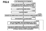
- Fig. 6 illustrates a flow of an operation of an ophthalmologic photographing apparatus according to a second exemplary embodiment of the present invention.
- Fig. 7 illustrates a flow of an operation of an ophthalmologic photographing apparatus according to a third exemplary embodiment of the present invention.
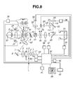
- Fig. 8 illustrates a configuration of an ophthalmologic photographing apparatus according to a fourth exemplary embodiment of the present invention.
- Fig. 9 illustrates a flow of an operation of the ophthalmologic photographing apparatus according to the fourth exemplary embodiment of the present invention.
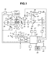
- Fig. 1 illustrates a configuration of an ophthalmologic photographing apparatus according to a first exemplary embodiment of the present invention.
- An observation light source 1 such as a halogen lamp, for emitting stationary light, a condenser lens 2, a filter 3 for transmitting infrared light and for cutting off visible light, a photographing light projecting light source 4, such as a flash unit, for projecting photographing light, a lens 5, and a mirror 6 are arranged on an optical axis L1.
- a ring diaphragm 7 having a ring-like opening, a relay lens 8, and a perforated mirror 10 having a central part opening, in which a diaphragm 9 is disposed, are sequentially arranged on an optical axis L2 extending in a reflecting direction of the mirror 6.
- the filter 3, functioning as a wavelength range switching unit, is placed differently depending upon which of the mydriatic photographing mode and the non-mydriatic photographing mode a photographing mode of the ophthalmologic photographing apparatus is.
- the photographing mode of the ophthalmologic photographing apparatus is the non-mydriatic photographing mode
- invisible range wavelength infrared light is irradiated onto the subject's eye E.
- the filter 3 is placed on the optical axis L1.
- the photographing mode of the ophthalmologic photographing apparatus is the mydriatic photographing mode
- visible range wavelength light is irradiated onto the subject's eye E.
- the filter 3 is moved out of the optical axis L1, as indicated by an arrow.
- An objective lens 11 is placed on an optical axis L3 extending in a reflecting direction of the perforated mirror 10 so as to be opposed to the subject's eye E.
- An anterior eye observation optical system 12 is removably placed on the optical axis L3 between the objective lens 11 and the perforated mirror 10.
- a lens 13, a target member 14, a prism 15 having an image splitting prism provided at a central portion thereof, and a lens 16 are arranged in the anterior eye observation optical system 12.
- a target illuminating light source 17 for illuminating the target member 14 from a side is placed in the vicinity of the target member 14.
- the prism 15 is located so as to be substantially conjugated with an anterior eye portion E p of the subject's eye E with respect to the objective lens 11 and the lens 13 when an operating distance between the subject's eye E and the objective lens 11 is appropriate.
- These members constituting the anterior eye observation optical system 12, can be removably and integrally inserted onto the optical axis L3.
- a focusing lens 18, a photographing lens 19, a flip-up mirror 20, and a still image sensor 21 are sequentially arranged in rear of the perforated mirror 10.
- the focusing lens 18 is moved on the optical axis L3 in order to adjust focusing.
- the flip-up mirror 20 serves to switch between a photographing optical system and an observation optical system.
- a dichroic mirror 22 for reflecting infrared light and for transmitting visible light is placed on an optical axis L4 extending in a reflecting direction of the flip-up mirror 20.
- a field lens 23, a lens 24, and an observation image sensor 25 are sequentially arranged on an optical axis L5 extending in a reflecting direction of the dichroic mirror 22.
- a fundus observation fixation target projecting unit 26 including a liquid crystal display panel and a backlight is located on an optical axis L6 in a transmitting direction of the dichroic mirror 22 so as to be optically conjugated with the still image sensor 21.
- the fundus observation fixation target projecting unit 26 projects the fixation target onto a predetermined area of a fundus portion E r of the subject's eye E in order to draw a line of sight of the subject's eye.
- a plurality of anterior eye illuminating light sources 27 directed to the subject's eye E are located in the neighborhood of the objective lens 11.
- An output of the still image sensor 21 is displayed on a monitor 39 via an image processing unit 31 and a control unit 32.
- an output of the observation image sensor 25 is displayed on the monitor 39 via the control unit 32.
- the control unit 32 controls the observation light source 1 via an observation light source control unit 33. Further, the control unit 32 controls the photographing light projecting light source 4 via a photographing light source control unit 34. Furthermore, the control unit 32 controls the target illuminating light source 17 of the anterior eye observation optical system 12 via the anterior eye observation fixation target light source control unit 35.
- the control unit 32 controls the fundus observation fixation target projecting unit 26 via a fundus observation fixation target light source control unit 36. Further, the control unit 32 controls the anterior eye illuminating light sources 27.
- a work memory 37, an image memory 38, a monitor 39, a keyboard 40, an observation region selecting switch 41, and a photographing switch 42 are connected to the control unit 32.
- the control unit 32 includes controllers, such as a central processing unit (CPU), and computer-readable memories, such as a read-only memory (ROM), which store programs for operating the ophthalmologic photographic apparatus.
- the control unit 32 can be constructed integrally with hardware, such as the observation light source control unit 33, the photographing light source control unit 34, the anterior eye observation fixation target light source control unit 35, and the fundus observation fixation target light source control unit 36.
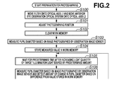
- Fig. 2 illustrates a flow of an operation performed by the control unit 32 of the ophthalmologic photographing apparatus according to the present embodiment.
- step S100 if the preparation for photographing is started, the control unit 32 performs a control process for moving the filter 3 onto the optical axis L1. Then, if an operation caused due to the observation region selecting switch 41 is detected, the control unit 32 performs a control process for inserting the anterior eye observation optical system 12 onto the optical axis L3. Thus, infrared light for observing the subject's eye E is projected thereonto. In addition, a photographing position can be adjusted using the anterior eye observation optical system 12.
- step S101 the photographing position is adjusted by an operator.
- the control unit 32 turns on the anterior eye illuminating light source 27.
- the control unit 32 turns on the target illuminating light source 17 at a predetermined amount of light via the anterior eye observation fixation target light source control unit 35.
- a light flux projected by the target illuminating light source 17 reaches the subject's eye E through the optical axis L3.
- the target illuminating light source 17 acts as a visible light projecting unit for projecting visible light onto the subject' s eye E.
- the target illuminating light source 17 projects light to the subject' s eye E in association with change in the amount of light projected thereto by adjusting an amount of light from the target illuminating light source 17.
- Light emitted from the anterior eye illuminating light source 27 illuminates the anterior eye portion E p of the subject's eye E.
- a light flux, which is reflection-scattered by the subject's eye E is reflected by the flip-up mirror 20 in the direction of the optical axis L4 via the objective lens 11, the anterior eye observation optical system 12, the photographing diaphragm 9, the focusing lens 18, and the photographing lens 19.
- the reflected light is formed into an image on the observation image sensor 25 by the field lens 23 and the lens 18 after being reflected by the dichroic mirror 22 in the direction of the optical axis L5. Then, the image photographed by the observation image sensor 25 is displayed on the monitor 39 by the control unit 32.
- An operator roughly adjusts the photographing position by manipulating an operating lever (not shown), while observing the image of the anterior eye portion Ep of the subject's eye E, which is displayed on the monitor 39.
- step S102 the control unit 32 clears the work memory 37.
- the work memory 37 is used for temporarily storing information that is acquired by the fundus camera and that represents measured values and amounts of change of the pupil diameter of the subject's eye E, the presence/absence of the application of a mydriatic to the subject's eye E, and the presence/absence of a myosis of the subject's eye E.
- step S103 the control unit 32 measures the pupil diameter based on an image photographed by the observation image sensor 25.
- the measurement of the pupil diameter is performed by transmitting the image photographed by the observation image sensor 25 to the control unit 32 and using a method of performing a method discussed in Japanese Patent Application Laid-Open No. 6-178762 or a method of obtaining the pupil diameter from the area of a pupil by approximating the pupil with a circle.
- the term "diameter” is used throughout the description for the sake of convenience. However, it is noted that any measurement of the pupil size, which is indicative of the degree to which a pupil is dilated, can be utilized. Consequently, the term “diameter” should not be considered to limit the scope of the invention by excluding other measurements of pupil size or degree of dilation.
- step S104 the control unit 32 causes the work memory 37 to store the measured value of the pupil diameter.
- step S105 the control unit 32 increases an amount of light from the target illuminating light source 17 by a preliminarily set amount via the anterior eye observation fixation target light source control unit 35. Subsequently, the control unit 32 waits for a predetermined time.
- step S106 the control unit 32 measures the pupil diameter by performing a procedure similar to that performed in step S103. Subsequently, the control unit 32 detects an amount of change in the pupil diameter by subtracting a measured value of the pupil diameter, which is measured after the amount of light is increased, from the measured value of the pupil diameter that is stored in the work memory 37 in step S104 and that is measured before the amount of light is increased.
- step S107 the control unit 32 determines whether an amount of change in the pupil diameter, which is detected in step S106, is less than a threshold. If the amount of change in the pupil diameter is equal to or more than the threshold (NO in step S107), the control unit 32 determines that the amount of change in the pupil diameter is large, and that non-mydriatic photographing is being performed. Thus, the control unit 32 proceeds to step S111 while the filter 3 is kept inserted onto the optical axis L1.
- step S108 if the control unit 32 determines based on a result of comparison made in step S107 that the amount of change in the pupil diameter is less than the threshold, the control unit 32 determines whether the amount of change is small because the amount of light from the target illuminating light source 17 is less than a threshold. If the control unit 32 determines based on a result of comparison that the amount of light from the target illuminating light source 17 is less than the threshold, the control unit 32 performs processing to be performed in step S105 or later again.
- step S109 if it is determined based on a result of the comparison made in step S108 that the amount of light is equal to or larger than the threshold, the control unit 32 determines that mydriatic photographing is being performed by applying a mydriatic to the subject's eye E. Thus, the control unit 32 causes the work memory 37 to store information indicating that mydriatic photographing is being performed, and information representing the amount of change in the pupil diameter acquired in step S106.
- step S110 the control unit 32 performs a control process for moving the filter 3 out of the optical axis L1.
- a light flux of light for observing the subject's eye E is set by the movement of the filter 3 to be that of visible light. This enables observing a color image of the subject's eye E.
- step S111 the control unit 32 performs a control process for moving the anterior eye observation optical system 12 out of the optical axis L3 via the anterior eye fixation target light source control unit 35.
- This movement of the anterior eye observation optical system 12 changes an image to be formed onto the still image sensor 21 or the observation image sensor 25 from an image of the anterior eye portion E p of the subject's eye E to an image of the fundus portion E r thereof.
- a fundus image can be photographed.
- step S112 the control unit 32 performs a control process for projecting an image of the fundus observation fixation target projecting unit 26 onto the fundus portion E r via the fundus observation fixation target light source control unit 36.
- the subject' s eye E is caused to perform fixation.
- the fundus portion E r is observed with visible light while the mydriatic photographing thereof is performed.
- the fundus portion E r is observed with infrared light using the filter 3.
- the control unit 32 detects an operation of the photographing switch 42, the control unit 32 instantaneously turns on the photographing light projecting light source 4.
- the photographing of a color fundus image is performed by the control unit 32 using the still image sensor 21.
- step S113 the control unit 32 causes an external storage medium (not shown) to store information representing the photographed image and the information stored in the work memory 37.
- step S114 the control unit 32 determines whether all necessary images have been photographed. If there is an image that is not photographed, the control unit 32 performs processing to be performed in step S112 or later again.
- fixed values can be used as values of the amount of light to be used for the adjustment of the position in step S101, the predetermined amount and the waiting time in step S105, and the thresholds used in steps S107 and S108.
- the parameters can be selected from a combination of a plurality of values. More alternatively, the parameters can be input from the keyboard 40 before the subject's eye E is photographed.
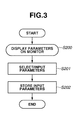
- Fig. 3 illustrates a flow of an operation of selecting the parameters.
- Fig. 4 illustrates a parameter set displayed by the monitor 39 when the operation of selecting and inputting the parameters is performed.
- step S200 if the setting of the parameters is started, the control unit 32 performs a process for displaying currently set values of the parameters on the monitor 39 in a format illustrated in Fig. 4 .
- the parameter set includes an initial amount of light A of the target illuminating light source 17 at the time of adjusting the position, a value B of an increase in the amount of light from the target illuminating light source 17 in a case where the amount of light from the target illuminating light source 17 is increased, a measurement waiting time C , a threshold D for an amount of change in the pupil diameter, and a threshold E for an amount of light from the target illuminating light source 17.
- a parameter set No. F is used for grouping and managing the set values.
- step S201 an operator selects or inputs the parameters displayed on the monitor 39 using the keyboard 40.
- the parameters are selected from a plurality of groups respectively constituted by combinations of the set values of the parameters A through E by changing the value of the parameter set No. F illustrated in Fig. 4 .
- the value of the parameter to be input is directly input from the keyboard 40.
- the control unit 32 acquires information representing the input parameter.
- step S202 the control unit 32 finishes setting of the parameters by storing the input parameters.
- the input parameter is stored in response to, e.g., detection of an input operation of a specific key of the keyboard 40.
- the setting of the parameters is performed before the preparation for photographing is performed.
- the amount A of light used in step S101, the predetermined amount B and the waiting time C used in step S104, and the threshold D used for comparison in step S108, and the threshold E used for comparison in step S109 can be changed.
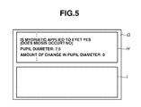
- Fig. 5 illustrates a format of each file G of content information and image information stored in the work memory 37, which are to be stored in an external storage medium.
- the file G stored in the work memory 37 includes header information H and image information I .
- Information indicating that a mydriatic is applied to the subject's eye E, information representing a measured value of the pupil diameter, and information representing an amount of change in the pupil diameter to be stored in the work memory 37 are stored as a part of the header information H .
- the control unit 32 causes the work memory 37 to store information indicating that no mydriatic is applied to the subject' s eye E, as the header information H . In this case, the control unit 32 does not cause the work memory 37 to store information representing an amount of change in the pupil diameter.
- the cause for making the amount of change in the pupil diameter less than the threshold is not always the application of a mydriatic to the subject's eye E. Accordingly, information indicating that a mydriatic is applied to the subject's eye E can be recorded as information representing the presence/absence of occurrence of myosis.
- the ophthalmologic photographing apparatus includes a unit configured to project visible range wavelength light, whose amount is variable, onto the subject's eye E using the target illuminating light source 17, and a unit configured to detect an amount of change in the pupil diameter of the subject's eye E, which is caused in association with the projection of the visible range wavelength light. Further, observation light used for observing the subject's eye E is changed, based on the amount or magnitude of the change in the pupil diameter, to the visible wavelength range or to the infrared wavelength range. Consequently, observation visible light can be prevented from being irradiated onto the pupil Ep in the non-mydriatic photographic mode.
- the ophthalmologic photographing apparatus further includes a unit configured to measure the pupil diameter of the subject' s eye E. Both of information representing the measured pupil diameter and information indicating that a mydriatic is applied to the subject's eye E are stored together with information representing the photographed image. This eliminates necessity for manually inputting a measured value. Occurrence of an inputting error can be prevented.
- the ophthalmologic photographing apparatus operates so as to change the photographing method by automatically determining whether a mydriatic is applied to the subject's eye E. Even in a case where an operator forgets to apply a mydriatic to the subject's eye E in the mydriatic photographic mode, the ophthalmologic photographing apparatus can photograph the fundus of the subject's eye E. Accordingly, there is a fear that after the fundus of subject's eye E is photographed, the operator may notice that the operator has forgotten to apply a mydriatic thereto.
- the ophthalmologic photographing apparatus can operate so as to detect the amount of change in the pupil diameter of the subject' s eye E, to give notice to an operator based on the amount of change in the pupil diameter, and to stop a photographing operation.
- Fig. 6 illustrates a flow of an operation of an ophthalmologic photographing apparatus according to a second exemplary embodiment of the present invention, which has a configuration illustrated in Fig. 1 and is adapted to give notice to an operator based on the amount of change in the pupil diameter, and to stop a photographing operation.
- the operation illustrated in Fig. 6 is performed under the control of the control unit 32 of the ophthalmologic photographing apparatus.
- processing to be performed in each of steps S300 through S314 is similar to that to be performed in associated one of steps S100 through S114.
- step S300 if the preparation for photographing is started, the control unit 32 performs a control process for moving the filter 3 onto the optical axis L1. Then, the control unit 32 performs a control process for inserting the anterior eye observation optical system 12 onto the optical axis L3. Thus, infrared light for observing the subject's eye E is projected there onto. In addition, a photographing position can be adjusted using the anterior eye observation optical system 12.
- step S301 the photographing position is adjusted by an operator. This adjustment of the photographing position is performed by a procedure similar to that performed in step S101 illustrated in Fig. 2 .
- step S302 the control unit 32 clears the work memory 37.
- step S303 the control unit 32 measures the pupil diameter based on an image photographed by the observation image sensor 25.
- the measurement of the pupil diameter is performed by a procedure similar to that performed in step S103 illustrated in Fig. 2 .
- step S304 the control unit 32 causes the work memory 37 to store the measured value of the pupil diameter.
- step S305 the control unit 32 increases an amount of light from the target illuminating light source 17 by a preliminarily set amount via the anterior eye observation fixation target light source control unit 35. Subsequently, the control unit 32 waits for a predetermined time.
- step S306 the control unit 32 measures the pupil diameter by performing a procedure similar to that performed in step S303. Subsequently, the control unit 32 detects an amount of change in the pupil diameter by subtracting a measured value of the pupil diameter measured in step S306 from the measured value of the pupil diameter that is stored in the work memory 37 in step S304.
- step S307 the control unit 32 determines whether an amount of change in the pupil diameter, which is acquired in step S306, is less than a threshold. If the amount of change in the pupil diameter is equal to or more than the threshold, the control unit 32 proceeds to step S315.
- step S308 if it is determined based on a result of comparison made in step S307 that the amount of change in the pupil diameter is less than the threshold, the control unit 32 determines whether the amount of light from the target illuminating light source 17 is less than a threshold. If it is determined based on a result of comparison made in step S308 that the amount of light from the target illuminating light source 17 is less than the threshold, the control unit 32 performs processing to be performed in step S305 or later again.
- step S309 if the control unit 32 determines based on a result of the comparison made in step S308 that the amount of light is equal to or more than the threshold, the control unit 32 causes the work memory 37 to store information indicating that mydriatic photographing is being performed, and information representing the amount of change in the pupil diameter acquired in step S306.
- step S310 the control unit 32 performs a control process for moving the filter 3 out of the optical axis L1.
- a light flux of light for observing the subject's eye E is set by the movement of the filter 3 to be that of visible light. This enables observing a color image of the subject's eye E.
- step S311 the control unit 32 performs a control process for moving the anterior eye observation optical system 12 out of the optical axis L3.
- This movement of the anterior eye observation optical system 12 changes an image to be formed onto the still image sensor 21 or the observation image sensor 25 from an image of the anterior eye portion E p of the subject's eye E to an image of the fundus portion E r thereof.
- step S312 the control unit 32 performs a control process for photographing a fundus image using the photographing light projecting light source 4 upon completion of preparation for photographing.
- step S313 the control unit 32 causes an external storage medium (not shown) to store information representing the photographed image and the information stored in the work memory 37.
- the file to be stored is similar to that according to the first exemplary embodiment illustrated in Fig. 5 .
- step S314 the control unit 32 determines whether all necessary images have been photographed. If there is an image that is not photographed, the control unit 32 performs processing to be performed in step S312 or later again.
- step S315 the control unit 32 notifies, if the control unit 32 determines in step S307 that the amount of change in the pupil diameter is equal to or more than the threshold, that mydriasis of the pupil does not occur. This notification is performed by causing the monitor 39 to indicate a message.
- step S316 the control unit 32 performs, after the processing is performed in step S315, a control process of causing an operator to determine whether the photographing operation is stopped.
- This control process is performed by causing the monitor 39 to indicate a message.
- the control unit 32 detects an operation of inputting data corresponding to a specific key, which corresponds to, e.g., a specific letter "Y" or "N", from the keyboard 40. Further, the control unit 32 determines input data represented by the specific key. Thus, the control unit 32 determines whether the photographing operation is stopped or continued. If the operator selects stoppage of the photographing, the photographing operation is stopped. If the operator selects continuation of the photographing, the control unit 32 proceeds to step S311.
- the ophthalmologic photographing apparatus when photographing is performed by the ophthalmologic photographing apparatus, the change in the pupil diameter is measured. Then, the photographing operation can be stopped by notifying, based on the amount of change in the pupil diameter, an operator that the mydriasis of the pupil does not occur. Accordingly, even in a case where an operator forgets to apply a mydriatic to the subject's eye E in the mydriatic photographing mode, the ophthalmologic photographing apparatus can give a warning to the operator before the photographing is performed.
- the ophthalmologic photographing apparatus is constructed such that an amount of change in the pupil diameter of the subject's eye E is measured by changing the amount of light from the target illuminating light source 17.
- the control process for changing the amount of light from the target illuminating light source 17 can be eliminated by using, as a light source for changing the amount of light, the observation light source 1 that serves as the observation light projecting unit.
- Fig. 7 illustrates a flow of an operation of an ophthalmologic photographing apparatus according to a third exemplary embodiment of the present invention, which has a configuration illustrated in Fig. 1 and is adapted to change, based on a change in the amount of light from the observation light source 1, a photographing mode.
- An operation illustrated in Fig. 7 is performed under the control of the control unit 32 of the ophthalmologic photographing apparatus.
- processing to be performed in each of steps S400 through S404, and S411 through S414 is similar to that to be performed in associated one of steps S100 through S104, and S111 through S114.
- step S400 if the preparation for photographing is started, the control unit 32 performs a control process for moving the filter 3 onto the optical axis L1. Then, the control unit 32 performs a control process for inserting the anterior eye observation optical system 12 onto the optical axis L3. Thus, infrared light for observing the subject's eye E is projected thereonto. In addition, a photographing position can be adjusted using the anterior eye observation optical system 12.
- step S401 the photographing position is adjusted by an operator.
- a fixed value is used as an amount of light from the target illuminating light source 17, without controlling the amount of light.
- the adjustment of the photographing position is performed by a procedure similar to that performed in step S101 illustrated in Fig. 2 .
- step S402 the control unit 32 clears the work memory 37.
- step S403 the control unit 32 measures the pupil diameter based on an image photographed by the observation image sensor 25.
- the measurement of the pupil diameter is performed by a procedure similar to that performed in step S103 illustrated in Fig. 2 .
- step S404 the control unit 32 causes the work memory 37 to store the measured value of the pupil diameter.
- step S405 the control unit 32 increases an amount of the observation light source 1 to a predetermined value.
- step S406 the control unit 32 waits for a predetermined time after the filter 3 is moved out of the optical axis L1. Visible light is projected onto the subject's eye E.
- step S407 the control unit 32 measures the pupil diameter by performing a procedure similar to that performed in step S403. Subsequently, the control unit 32 detects an amount of change in the pupil diameter by subtracting a measured value of the pupil diameter measured in step S407 from the measured value of the pupil diameter that is stored in the work memory 37 in step S404.
- step S408 the control unit 32 determines whether an amount of change in the pupil diameter is less than a threshold. If the amount of change in the pupil diameter is less than the threshold, the control unit 32 proceeds to step S409. If the amount of change in the pupil diameter is not less than the threshold, the control unit 32 proceeds to step S416.
- step S409 the control unit 32 determines whether the amount of light from the observation light source 1 is less than a threshold.
- step S410 if the control unit 32 determines based on a result of the comparison made in step S409 that the amount of light is equal to or more than the threshold, the control unit 32 causes the work memory 37 to store information indicating that a mydriatic is applied to the subject's eye E, and information representing the amount of change in the pupil diameter acquired in step S407.
- step S411 the control unit 32 performs a control process for moving the anterior eye observation optical system 12 out of the optical axis L3.
- This movement of the anterior eye observation optical system 12 changes an image to be formed onto the still image sensor 21 or the observation image sensor 25 from an image of the anterior eye portion E p of the subject's eye E to an image of the fundus portion E r thereof.
- step S412 the control unit 32 performs a control process for photographing a fundus image upon completion of preparation for photographing.
- step S413 the control unit 32 causes an external storage medium (not shown) to store information representing the photographed image and the information stored in the work memory 37 as a file.
- step S414 the control unit 32 determines whether all necessary images have been photographed. If there is an image that is not photographed, the control unit 32 performs processing to be performed in step S412 or later again.
- step S415 if the control unit 32 determines based on a result of comparison made in step S409 that the amount of light from the observation light source 1 is less than the threshold, the control unit 32 waits for a predetermined time after the amount of light from the observation light source 1 is increased to a preliminarily set amount under the control of the control unit 32. Then, the control unit 32 performs processing to be performed in step S407 or later again.
- step S416 if the control unit 32 determines in step S408 that the amount of change in the pupil diameter is equal to or more than the threshold, the control unit 32 performs a control process for moving the filter 3 onto the optical axis L1. Infrared light is projected onto the subject's eye E by moving the filter 3 onto the optical axis L1. Then, the control unit 32 proceeds to step S411.
- the information displayed on the monitor 39 in the case of selecting and inputting the parameters is similar to that illustrated in Fig. 4 .
- the process for controlling the amount of light from the target illuminating light source 17 can be eliminated using the observation light source 1 as the light source for changing the amount of light. Consequently, the configuration of the ophthalmologic photographing apparatus can be simplified.
- the photographing mode is switched by measuring the pupil diameter before a fundus image is photographed, and the amount of change in the pupil diameter after the fundus image is photographed.
- the amount of change in the pupil diameter before a fundus is photographed there is needed a processing time before the fundus is photographed.
- the ophthalmologic photographing apparatus can be configured such that the photographing mode is switched by measuring the pupil diameter before the fundus image is photographed and the change in the pupil diameter after the fundus image is photographed.
- Fig. 8 illustrates a configuration of an ophthalmologic photographing apparatus according to a fourth exemplary embodiment of the present invention, in which an optical system is added to the ophthalmologic photographing apparatus according to the first through third exemplary embodiments so as to be able to measure both of the pupil diameter before the fundus image is photographed and the change in the pupil diameter after the fundus image is photographed. That is, a prism 51 is located on the optical axis L3 between the perforated mirror 10 and the focusing lens 18. A lens 52 and an anterior eye observation image sensor 53 connected to the control unit 32 are located on an optical axis L7, which is formed by the prism 51.
- the anterior eye observation image sensor 53 is located so as to be substantially conjugated with the anterior eye portion E p of the subject's eye E with respect to the objective lens 11 and the lens 52 when an operating distance between the subject's eye E and the objective lens 11 is appropriate.
- Fig. 9 illustrates a flow of an operation of switching, based on the amount of change in the pupil diameter, a method for photographing a fundus image using a fundus camera. An operation illustrated in Fig. 9 is performed under the control of the control unit 32 of the ophthalmologic photographing apparatus.
- step S500 if the preparation for photographing is started, the control unit 32 performs a control process for moving the filter 3 onto the optical axis L1. Then, the control unit 32 performs a control process for inserting the anterior eye observation optical system 12 onto the optical axis L3. Thus, infrared light for observing the subject's eye E is projected thereonto. In addition, a photographing position can be adjusted using the anterior eye observation optical system 12.
- step S501 the control unit 32 performs a control process for adjusting the photographing position.
- the adjustment of the photographing position is performed by a procedure similar to that performed in step S101 illustrated in Fig. 2 .
- step S502 the control unit 32 clears the work memory 37.
- step S503 the control unit 32 performs a control process for moving the anterior eye observation optical system 12 out of the optical axis L3.
- This movement of the anterior eye observation optical system 12 changes an image to be formed onto the still image sensor 21 or the observation image sensor 25 from an image of the anterior eye portion E p of the subject's eye E to an image of the fundus portion E r thereof. With this operation, a fundus image can be photographed.
- an image of the anterior eye portion E p of the subject's eye E is formed on the anterior eye observation image sensor 53.
- step S504 the control unit 32 measures the pupil diameter based on an image of the anterior eye portion E p of the subject' s eye E photographed by the anterior eye observation image sensor 53.
- the measurement of the pupil diameter is performed by a procedure similar to that performed in step S103 illustrated in Fig. 2 .
- step S505 the control unit 32 causes the work memory 37 to store the measured value of the pupil diameter. Thus, the preparation for photographing is completed.
- step S506 the control unit 32 performs fundus image photographing upon completion of preparation for photographing.
- step S507 the control unit 32 causes an external storage medium (not shown) to store information representing the photographed image and the information stored in the work memory 37 as a file.
- step S508 the control unit 32 determines whether all necessary images have been photographed. If there is no image that is not photographed, photographing is finished.
- step S509 if there is an image that is not photographed, the control unit 32 measures a pupil diameter by a procedure similar to that performed in step S504. Then, the control unit 32 detects an amount of change in the pupil diameter by subtracting a measured value of the pupil diameter measured in step S509 from the measured value of the pupil diameter stored in the work memory 37 in step S505.
- step S510 the control unit 32 determines whether the amount of change in the pupil diameter, which is acquired in step S509, is less than a threshold.
- step S511 the control unit 32 notifies, if the control unit 32 determines in step S510 that the amount of change in the pupil diameter is equal to or more than the threshold, that mydriasis of the pupil is insufficient. This notification is performed by indicating a message on the monitor 39.
- step S512 the control unit 32 performs a control process for causing an operator to determine whether the photographing operation is stopped. Then, the control unit 32 causes the monitor 39 to display a message. Simultaneously, the control unit 32 detects an operation of inputting data corresponding to a specific key, which corresponds to, e.g., a specific letter "Y" or "N", from the keyboard 40. If the control unit 32 detects data representing stoppage of photographing, the control unit 32 stops a photographing operation. If the control unit 32 detects data representing continuation of photographing, the control unit 32 performs processing to be performed in step S509 or later again.
- a specific key which corresponds to, e.g., a specific letter "Y" or "N"
- step S513 if the control unit 32 determines, based on a result of comparison made in step S510, that the amount of change in the pupil diameter is less than the threshold, the control unit 32 causes the work memory 37 to store both of information indicating that a mydriatic is applied to the subject' s eye E and information representing an amount of change in the pupil diameter, which is acquired in step S509.
- step S514 the control unit 32 performs a control process for moving the filter 3 out of the optical axis L1. Then, the control unit 32 performs processing to be performed in step S509 or later again. Visible light is projected onto the subject's eye E by moving the filter 3 out of the optical axis L1. Consequently, a color image of the fundus portion E r of the subject's eye E can be observed.
- the ophthalmologic photographing apparatus is constructed to use the photographing light projecting light source 4 and to measure the amount of change in the pupil diameter between a state before photographing is performed and a state after photographing is performed. This eliminates the necessity for measuring an amount of change in the pupil diameter before a fundus image is photographed. Consequently, a time taken to enable photographing a fundus image can be shortened.
Abstract
Description
- The present invention relates to an ophthalmologic photographing apparatus used in photographing a fundus of a subject's eye at an ophthalmologic clinic.
- Hitherto, two types of photographing methods, i.e., a mydriatic photographing method and a non-mydriatic photographing method, have been known as methods for photographing fundus images. According to the mydriatic photographing method, fundus photographing is performed by illuminating a fundus of a subject's eye with visible light at both of the time of observing the fundus of the subject's eye and the time of photographing thereof using a mydriatic. According to the non-mydriatic photographing method, fundus photographing is performed without using a mydriatic by illuminating a fundus of a subject's eye with infrared light at the time of observing the fundus of the subject's eye, and illuminating the fundus of the subject' s eye with visible light at the time of photographing thereof.
- Hitherto, the mydriatic photographing method and the non-mydriatic photographing method have been respectively performed using different apparatuses. Recently, an apparatus capable of performing both of the mydriatic photographing method and the non-mydriatic photographing method has been proposed.
- Japanese Patent Application Laid-Open No.
9-140672 - On the other hand, there have been demands for storing, when the mydriatic photographing method of photographing a fundus of a subject's eye is performed using a mydriatic, information representing a pupil diameter together with image information at the time of photographing the fundus.
Techniques for automatically measuring a value of the pupil diameter are discussed as conventional techniques effective for the purpose. - Japanese Patent Application Laid-Open No.
6-178762 - The fundus camera discussed in Japanese Patent Application Laid-Open No.
9-140672 - When an operation of the fundus camera is transferred to a mydriatic photographing mode, the fundus of a subject's eye is illuminated with visible light when the subject's eye is observed. However, in a case where no mydriatic is used, myosis of the subject' s eye is induced. There is a minimum value of a pupil diameter photographable by each ordinary fundus camera. When the myosis of the subject's eye occurs, the pupil diameter thereof becomes less than the minimum pupil diameter. Consequently, the fundus of the subject's eye cannot be photographed.
- At that time, it is necessary for photographing the fundus of the subject's eye to wait until the pupil diameter of the subject's eye, which is increased due to natural mydriasis, exceeds the minimum value of the pupil diameter photographable by the fundus camera. A time required by the pupil diameter to exceed the minimum value due to natural mydriasis varies with environment and differences among individual subjects. Thus, such a time may be several minutes. In such a time, the fundus of the subject's eye cannot be photographed. Consequently, efficiency in photographing the fundus is lowered.
- Further, Japanese Patent Application Laid-Open No.
6-178762 - The present invention is directed to an ophthalmologic photographing apparatus capable of determining whether or not a mydriatic has been applied. Advantageously, this information can be used to prevent an operation mode thereof from being, at non-mydriatic photographing, switched to a mydriatic photographing mode due to an operator error. Further, the present invention is also directed to an ophthalmologic photographing apparatus capable of preventing an erroneous value of a pupil diameter measured at the time of photographing from being added to image information and stored.
- According to the present invention, there is provided an ophthalmologic photographing apparatus as specified in
claims 1 to 13. - Further features and aspects of the present invention will become apparent from the following detailed description of exemplary embodiments with reference to the attached drawings.
- The accompanying drawings, which are incorporated in and constitute a part of the specification, illustrate exemplary embodiments, features, and aspects of the invention and, together with the description, serve to explain the principles of the invention.
-
Fig. 1 illustrates a configuration of an ophthalmologic photographing apparatus according to a first exemplary embodiment of the present invention. -
Fig. 2 illustrates a flow of an operation of the ophthalmologic photographing apparatus according to the first exemplary embodiment of the present invention. -
Fig. 3 illustrates a flow of an operation of selecting and inputting parameters in the ophthalmologic photographing apparatus according to the first exemplary embodiment of the present invention. -
Fig. 4 illustrates a parameter set displayed by a monitor of the ophthalmologic photographing apparatus according to the first exemplary embodiment of the present invention in the operation of selecting and inputting parameters. -
Fig. 5 illustrates a format of a file to be stored in an external storage medium. -
Fig. 6 illustrates a flow of an operation of an ophthalmologic photographing apparatus according to a second exemplary embodiment of the present invention. -
Fig. 7 illustrates a flow of an operation of an ophthalmologic photographing apparatus according to a third exemplary embodiment of the present invention. -
Fig. 8 illustrates a configuration of an ophthalmologic photographing apparatus according to a fourth exemplary embodiment of the present invention. -
Fig. 9 illustrates a flow of an operation of the ophthalmologic photographing apparatus according to the fourth exemplary embodiment of the present invention. - Various exemplary embodiments, features, and aspects of the invention will be described in detail below with reference to the drawings.
-
Fig. 1 illustrates a configuration of an ophthalmologic photographing apparatus according to a first exemplary embodiment of the present invention. Anobservation light source 1, such as a halogen lamp, for emitting stationary light, acondenser lens 2, afilter 3 for transmitting infrared light and for cutting off visible light, a photographing light projectinglight source 4, such as a flash unit, for projecting photographing light, alens 5, and amirror 6 are arranged on an optical axis L1. On the other hand, aring diaphragm 7 having a ring-like opening, arelay lens 8, and aperforated mirror 10 having a central part opening, in which adiaphragm 9 is disposed, are sequentially arranged on an optical axis L2 extending in a reflecting direction of themirror 6. - The
filter 3, functioning as a wavelength range switching unit, is placed differently depending upon which of the mydriatic photographing mode and the non-mydriatic photographing mode a photographing mode of the ophthalmologic photographing apparatus is. In a case where the photographing mode of the ophthalmologic photographing apparatus is the non-mydriatic photographing mode, invisible range wavelength infrared light is irradiated onto the subject's eye E. Thus, thefilter 3 is placed on the optical axis L1. In a case where the photographing mode of the ophthalmologic photographing apparatus is the mydriatic photographing mode, visible range wavelength light is irradiated onto the subject's eye E. Thus, thefilter 3 is moved out of the optical axis L1, as indicated by an arrow. - An
objective lens 11 is placed on an optical axis L3 extending in a reflecting direction of theperforated mirror 10 so as to be opposed to the subject's eye E. An anterior eye observationoptical system 12 is removably placed on the optical axis L3 between theobjective lens 11 and theperforated mirror 10. Alens 13, atarget member 14, a prism 15 having an image splitting prism provided at a central portion thereof, and alens 16 are arranged in the anterior eye observationoptical system 12. A target illuminating light source 17 for illuminating thetarget member 14 from a side is placed in the vicinity of thetarget member 14. The prism 15 is located so as to be substantially conjugated with an anterior eye portion Ep of the subject's eye E with respect to theobjective lens 11 and thelens 13 when an operating distance between the subject's eye E and theobjective lens 11 is appropriate. These members, constituting the anterior eye observationoptical system 12, can be removably and integrally inserted onto the optical axis L3. - A focusing
lens 18, a photographinglens 19, a flip-up mirror 20, and a stillimage sensor 21 are sequentially arranged in rear of theperforated mirror 10. The focusinglens 18 is moved on the optical axis L3 in order to adjust focusing. The flip-upmirror 20 serves to switch between a photographing optical system and an observation optical system. Adichroic mirror 22 for reflecting infrared light and for transmitting visible light is placed on an optical axis L4 extending in a reflecting direction of the flip-upmirror 20. - A
field lens 23, alens 24, and anobservation image sensor 25 are sequentially arranged on an optical axis L5 extending in a reflecting direction of thedichroic mirror 22. - A fundus observation fixation
target projecting unit 26 including a liquid crystal display panel and a backlight is located on an optical axis L6 in a transmitting direction of thedichroic mirror 22 so as to be optically conjugated with the stillimage sensor 21. The fundus observation fixationtarget projecting unit 26 projects the fixation target onto a predetermined area of a fundus portion Er of the subject's eye E in order to draw a line of sight of the subject's eye. In addition, a plurality of anterior eye illuminatinglight sources 27 directed to the subject's eye E are located in the neighborhood of theobjective lens 11. - An output of the
still image sensor 21 is displayed on amonitor 39 via animage processing unit 31 and acontrol unit 32. On the other hand, an output of theobservation image sensor 25 is displayed on themonitor 39 via thecontrol unit 32. Thecontrol unit 32 controls the observationlight source 1 via an observation lightsource control unit 33. Further, thecontrol unit 32 controls the photographing light projectinglight source 4 via a photographing lightsource control unit 34. Furthermore, thecontrol unit 32 controls the target illuminating light source 17 of the anterior eye observationoptical system 12 via the anterior eye observation fixation target lightsource control unit 35. Thecontrol unit 32 controls the fundus observation fixationtarget projecting unit 26 via a fundus observation fixation target lightsource control unit 36. Further, thecontrol unit 32 controls the anterior eye illuminatinglight sources 27. - A
work memory 37, animage memory 38, amonitor 39, akeyboard 40, an observationregion selecting switch 41, and a photographingswitch 42 are connected to thecontrol unit 32. Thecontrol unit 32 includes controllers, such as a central processing unit (CPU), and computer-readable memories, such as a read-only memory (ROM), which store programs for operating the ophthalmologic photographic apparatus. Incidentally, thecontrol unit 32 can be constructed integrally with hardware, such as the observation lightsource control unit 33, the photographing lightsource control unit 34, the anterior eye observation fixation target lightsource control unit 35, and the fundus observation fixation target lightsource control unit 36. -
Fig. 2 illustrates a flow of an operation performed by thecontrol unit 32 of the ophthalmologic photographing apparatus according to the present embodiment. - In step S100, if the preparation for photographing is started, the
control unit 32 performs a control process for moving thefilter 3 onto the optical axis L1. Then, if an operation caused due to the observationregion selecting switch 41 is detected, thecontrol unit 32 performs a control process for inserting the anterior eye observationoptical system 12 onto the optical axis L3. Thus, infrared light for observing the subject's eye E is projected thereonto. In addition, a photographing position can be adjusted using the anterior eye observationoptical system 12. - In step S101, the photographing position is adjusted by an operator. First, the
control unit 32 turns on the anterior eye illuminatinglight source 27. Then, thecontrol unit 32 turns on the target illuminating light source 17 at a predetermined amount of light via the anterior eye observation fixation target lightsource control unit 35. A light flux projected by the target illuminating light source 17 reaches the subject's eye E through the optical axis L3. The target illuminating light source 17 acts as a visible light projecting unit for projecting visible light onto the subject' s eye E. The target illuminating light source 17 projects light to the subject' s eye E in association with change in the amount of light projected thereto by adjusting an amount of light from the target illuminating light source 17. - Light emitted from the anterior eye illuminating
light source 27 illuminates the anterior eye portion Ep of the subject's eye E. A light flux, which is reflection-scattered by the subject's eye E, is reflected by the flip-upmirror 20 in the direction of the optical axis L4 via theobjective lens 11, the anterior eye observationoptical system 12, the photographingdiaphragm 9, the focusinglens 18, and the photographinglens 19. The reflected light is formed into an image on theobservation image sensor 25 by thefield lens 23 and thelens 18 after being reflected by thedichroic mirror 22 in the direction of the optical axis L5. Then, the image photographed by theobservation image sensor 25 is displayed on themonitor 39 by thecontrol unit 32. - An operator roughly adjusts the photographing position by manipulating an operating lever (not shown), while observing the image of the anterior eye portion Ep of the subject's eye E, which is displayed on the
monitor 39. - In step S102, the
control unit 32 clears thework memory 37. Thework memory 37 is used for temporarily storing information that is acquired by the fundus camera and that represents measured values and amounts of change of the pupil diameter of the subject's eye E, the presence/absence of the application of a mydriatic to the subject's eye E, and the presence/absence of a myosis of the subject's eye E. - In step S103, the
control unit 32 measures the pupil diameter based on an image photographed by theobservation image sensor 25. The measurement of the pupil diameter is performed by transmitting the image photographed by theobservation image sensor 25 to thecontrol unit 32 and using a method of performing a method discussed in Japanese Patent Application Laid-Open No.6-178762 - The term "diameter" is used throughout the description for the sake of convenience. However, it is noted that any measurement of the pupil size, which is indicative of the degree to which a pupil is dilated, can be utilized. Consequently, the term "diameter" should not be considered to limit the scope of the invention by excluding other measurements of pupil size or degree of dilation.
- In step S104, the
control unit 32 causes thework memory 37 to store the measured value of the pupil diameter. - In step S105, the
control unit 32 increases an amount of light from the target illuminating light source 17 by a preliminarily set amount via the anterior eye observation fixation target lightsource control unit 35. Subsequently, thecontrol unit 32 waits for a predetermined time. - In step S106, the
control unit 32 measures the pupil diameter by performing a procedure similar to that performed in step S103. Subsequently, thecontrol unit 32 detects an amount of change in the pupil diameter by subtracting a measured value of the pupil diameter, which is measured after the amount of light is increased, from the measured value of the pupil diameter that is stored in thework memory 37 in step S104 and that is measured before the amount of light is increased. - In step S107, the
control unit 32 determines whether an amount of change in the pupil diameter, which is detected in step S106, is less than a threshold. If the amount of change in the pupil diameter is equal to or more than the threshold (NO in step S107), thecontrol unit 32 determines that the amount of change in the pupil diameter is large, and that non-mydriatic photographing is being performed. Thus, thecontrol unit 32 proceeds to step S111 while thefilter 3 is kept inserted onto the optical axis L1. - In step S108, if the
control unit 32 determines based on a result of comparison made in step S107 that the amount of change in the pupil diameter is less than the threshold, thecontrol unit 32 determines whether the amount of change is small because the amount of light from the target illuminating light source 17 is less than a threshold. If thecontrol unit 32 determines based on a result of comparison that the amount of light from the target illuminating light source 17 is less than the threshold, thecontrol unit 32 performs processing to be performed in step S105 or later again. - In step S109, if it is determined based on a result of the comparison made in step S108 that the amount of light is equal to or larger than the threshold, the
control unit 32 determines that mydriatic photographing is being performed by applying a mydriatic to the subject's eye E. Thus, thecontrol unit 32 causes thework memory 37 to store information indicating that mydriatic photographing is being performed, and information representing the amount of change in the pupil diameter acquired in step S106. - In step S110, the
control unit 32 performs a control process for moving thefilter 3 out of the optical axis L1. A light flux of light for observing the subject's eye E is set by the movement of thefilter 3 to be that of visible light. This enables observing a color image of the subject's eye E. - In step S111, the
control unit 32 performs a control process for moving the anterior eye observationoptical system 12 out of the optical axis L3 via the anterior eye fixation target lightsource control unit 35. This movement of the anterior eye observationoptical system 12 changes an image to be formed onto thestill image sensor 21 or theobservation image sensor 25 from an image of the anterior eye portion Ep of the subject's eye E to an image of the fundus portion Er thereof. Thus, a fundus image can be photographed. - In step S112, the
control unit 32 performs a control process for projecting an image of the fundus observation fixationtarget projecting unit 26 onto the fundus portion Er via the fundus observation fixation target lightsource control unit 36. Thus, the subject' s eye E is caused to perform fixation. The fundus portion Er is observed with visible light while the mydriatic photographing thereof is performed. On the other hand, while the non-mydriatic photographing of the fundus portion Er is performed, the fundus portion Er is observed with infrared light using thefilter 3. Then, if thecontrol unit 32 detects an operation of the photographingswitch 42, thecontrol unit 32 instantaneously turns on the photographing light projectinglight source 4. Thus, the photographing of a color fundus image is performed by thecontrol unit 32 using thestill image sensor 21. - In step S113, the
control unit 32 causes an external storage medium (not shown) to store information representing the photographed image and the information stored in thework memory 37. - In step S114, the
control unit 32 determines whether all necessary images have been photographed. If there is an image that is not photographed, thecontrol unit 32 performs processing to be performed in step S112 or later again. Incidentally, fixed values can be used as values of the amount of light to be used for the adjustment of the position in step S101, the predetermined amount and the waiting time in step S105, and the thresholds used in steps S107 and S108. Alternatively, the parameters can be selected from a combination of a plurality of values. More alternatively, the parameters can be input from thekeyboard 40 before the subject's eye E is photographed. -
Fig. 3 illustrates a flow of an operation of selecting the parameters.Fig. 4 illustrates a parameter set displayed by themonitor 39 when the operation of selecting and inputting the parameters is performed. - In step S200, if the setting of the parameters is started, the
control unit 32 performs a process for displaying currently set values of the parameters on themonitor 39 in a format illustrated inFig. 4 . - As illustrated in
Fig. 4 , the parameter set includes an initial amount of light A of the target illuminating light source 17 at the time of adjusting the position, a value B of an increase in the amount of light from the target illuminating light source 17 in a case where the amount of light from the target illuminating light source 17 is increased, a measurement waiting time C, a threshold D for an amount of change in the pupil diameter, and a threshold E for an amount of light from the target illuminating light source 17. A parameter set No. F is used for grouping and managing the set values. - In step S201, an operator selects or inputs the parameters displayed on the
monitor 39 using thekeyboard 40. The parameters are selected from a plurality of groups respectively constituted by combinations of the set values of the parameters A through E by changing the value of the parameter set No. F illustrated inFig. 4 . In a case where the selected parameters are changed or input, the value of the parameter to be input is directly input from thekeyboard 40. Thecontrol unit 32 acquires information representing the input parameter. - In step S202, the
control unit 32 finishes setting of the parameters by storing the input parameters. The input parameter is stored in response to, e.g., detection of an input operation of a specific key of thekeyboard 40. The setting of the parameters is performed before the preparation for photographing is performed. Thus, the amount A of light used in step S101, the predetermined amount B and the waiting time C used in step S104, and the threshold D used for comparison in step S108, and the threshold E used for comparison in step S109 can be changed. -
Fig. 5 illustrates a format of each file G of content information and image information stored in thework memory 37, which are to be stored in an external storage medium. The file G stored in thework memory 37 includes header information H and image information I. Information indicating that a mydriatic is applied to the subject's eye E, information representing a measured value of the pupil diameter, and information representing an amount of change in the pupil diameter to be stored in thework memory 37 are stored as a part of the header information H. - In a case where information indicating that a mydriatic is applied to the subject's eye E, information representing a measured value of the pupil diameter, and information representing an amount of change in the pupil diameter are not stored in the
work memory 37, thecontrol unit 32 causes thework memory 37 to store information indicating that no mydriatic is applied to the subject' s eye E, as the header information H. In this case, thecontrol unit 32 does not cause thework memory 37 to store information representing an amount of change in the pupil diameter. Incidentally, the cause for making the amount of change in the pupil diameter less than the threshold is not always the application of a mydriatic to the subject's eye E. Accordingly, information indicating that a mydriatic is applied to the subject's eye E can be recorded as information representing the presence/absence of occurrence of myosis. - Thus, the ophthalmologic photographing apparatus according to the first exemplary embodiment includes a unit configured to project visible range wavelength light, whose amount is variable, onto the subject's eye E using the target illuminating light source 17, and a unit configured to detect an amount of change in the pupil diameter of the subject's eye E, which is caused in association with the projection of the visible range wavelength light. Further, observation light used for observing the subject's eye E is changed, based on the amount or magnitude of the change in the pupil diameter, to the visible wavelength range or to the infrared wavelength range. Consequently, observation visible light can be prevented from being irradiated onto the pupil Ep in the non-mydriatic photographic mode.
- The ophthalmologic photographing apparatus according to the first exemplary embodiment further includes a unit configured to measure the pupil diameter of the subject' s eye E. Both of information representing the measured pupil diameter and information indicating that a mydriatic is applied to the subject's eye E are stored together with information representing the photographed image. This eliminates necessity for manually inputting a measured value. Occurrence of an inputting error can be prevented.
- According to the first exemplary embodiment, the ophthalmologic photographing apparatus operates so as to change the photographing method by automatically determining whether a mydriatic is applied to the subject's eye E. Even in a case where an operator forgets to apply a mydriatic to the subject's eye E in the mydriatic photographic mode, the ophthalmologic photographing apparatus can photograph the fundus of the subject's eye E. Accordingly, there is a fear that after the fundus of subject's eye E is photographed, the operator may notice that the operator has forgotten to apply a mydriatic thereto.
- Consequently, according to the procedure described in the description of the first exemplary embodiment, the ophthalmologic photographing apparatus can operate so as to detect the amount of change in the pupil diameter of the subject' s eye E, to give notice to an operator based on the amount of change in the pupil diameter, and to stop a photographing operation.
-
Fig. 6 illustrates a flow of an operation of an ophthalmologic photographing apparatus according to a second exemplary embodiment of the present invention, which has a configuration illustrated inFig. 1 and is adapted to give notice to an operator based on the amount of change in the pupil diameter, and to stop a photographing operation. The operation illustrated inFig. 6 is performed under the control of thecontrol unit 32 of the ophthalmologic photographing apparatus. Incidentally, processing to be performed in each of steps S300 through S314 is similar to that to be performed in associated one of steps S100 through S114. - In step S300, if the preparation for photographing is started, the
control unit 32 performs a control process for moving thefilter 3 onto the optical axis L1. Then, thecontrol unit 32 performs a control process for inserting the anterior eye observationoptical system 12 onto the optical axis L3. Thus, infrared light for observing the subject's eye E is projected there onto. In addition, a photographing position can be adjusted using the anterior eye observationoptical system 12. - In step S301, the photographing position is adjusted by an operator. This adjustment of the photographing position is performed by a procedure similar to that performed in step S101 illustrated in
Fig. 2 . - In step S302, the
control unit 32 clears thework memory 37. - In step S303, the
control unit 32 measures the pupil diameter based on an image photographed by theobservation image sensor 25. The measurement of the pupil diameter is performed by a procedure similar to that performed in step S103 illustrated inFig. 2 . - In step S304, the
control unit 32 causes thework memory 37 to store the measured value of the pupil diameter. - In step S305, the
control unit 32 increases an amount of light from the target illuminating light source 17 by a preliminarily set amount via the anterior eye observation fixation target lightsource control unit 35. Subsequently, thecontrol unit 32 waits for a predetermined time. - In step S306, the
control unit 32 measures the pupil diameter by performing a procedure similar to that performed in step S303. Subsequently, thecontrol unit 32 detects an amount of change in the pupil diameter by subtracting a measured value of the pupil diameter measured in step S306 from the measured value of the pupil diameter that is stored in thework memory 37 in step S304. - In step S307, the
control unit 32 determines whether an amount of change in the pupil diameter, which is acquired in step S306, is less than a threshold. If the amount of change in the pupil diameter is equal to or more than the threshold, thecontrol unit 32 proceeds to step S315. - In step S308, if it is determined based on a result of comparison made in step S307 that the amount of change in the pupil diameter is less than the threshold, the
control unit 32 determines whether the amount of light from the target illuminating light source 17 is less than a threshold. If it is determined based on a result of comparison made in step S308 that the amount of light from the target illuminating light source 17 is less than the threshold, thecontrol unit 32 performs processing to be performed in step S305 or later again. - In step S309, if the
control unit 32 determines based on a result of the comparison made in step S308 that the amount of light is equal to or more than the threshold, thecontrol unit 32 causes thework memory 37 to store information indicating that mydriatic photographing is being performed, and information representing the amount of change in the pupil diameter acquired in step S306. - In step S310, the
control unit 32 performs a control process for moving thefilter 3 out of the optical axis L1. A light flux of light for observing the subject's eye E is set by the movement of thefilter 3 to be that of visible light. This enables observing a color image of the subject's eye E. - In step S311, the
control unit 32 performs a control process for moving the anterior eye observationoptical system 12 out of the optical axis L3. This movement of the anterior eye observationoptical system 12 changes an image to be formed onto thestill image sensor 21 or theobservation image sensor 25 from an image of the anterior eye portion Ep of the subject's eye E to an image of the fundus portion Er thereof. - In step S312, the
control unit 32 performs a control process for photographing a fundus image using the photographing light projectinglight source 4 upon completion of preparation for photographing. - In step S313, the
control unit 32 causes an external storage medium (not shown) to store information representing the photographed image and the information stored in thework memory 37. Incidentally, the file to be stored is similar to that according to the first exemplary embodiment illustrated inFig. 5 . - In step S314, the
control unit 32 determines whether all necessary images have been photographed. If there is an image that is not photographed, thecontrol unit 32 performs processing to be performed in step S312 or later again. - In step S315, the
control unit 32 notifies, if thecontrol unit 32 determines in step S307 that the amount of change in the pupil diameter is equal to or more than the threshold, that mydriasis of the pupil does not occur. This notification is performed by causing themonitor 39 to indicate a message. - In step S316, the
control unit 32 performs, after the processing is performed in step S315, a control process of causing an operator to determine whether the photographing operation is stopped. This control process is performed by causing themonitor 39 to indicate a message. Then, thecontrol unit 32 detects an operation of inputting data corresponding to a specific key, which corresponds to, e.g., a specific letter "Y" or "N", from thekeyboard 40. Further, thecontrol unit 32 determines input data represented by the specific key. Thus, thecontrol unit 32 determines whether the photographing operation is stopped or continued. If the operator selects stoppage of the photographing, the photographing operation is stopped. If the operator selects continuation of the photographing, thecontrol unit 32 proceeds to step S311. - Thus, according to the present embodiment, when photographing is performed by the ophthalmologic photographing apparatus, the change in the pupil diameter is measured. Then, the photographing operation can be stopped by notifying, based on the amount of change in the pupil diameter, an operator that the mydriasis of the pupil does not occur. Accordingly, even in a case where an operator forgets to apply a mydriatic to the subject's eye E in the mydriatic photographing mode, the ophthalmologic photographing apparatus can give a warning to the operator before the photographing is performed.
- According to the first and second exemplary embodiments, the ophthalmologic photographing apparatus is constructed such that an amount of change in the pupil diameter of the subject's eye E is measured by changing the amount of light from the target illuminating light source 17. However, the control process for changing the amount of light from the target illuminating light source 17 can be eliminated by using, as a light source for changing the amount of light, the observation
light source 1 that serves as the observation light projecting unit. -
Fig. 7 illustrates a flow of an operation of an ophthalmologic photographing apparatus according to a third exemplary embodiment of the present invention, which has a configuration illustrated inFig. 1 and is adapted to change, based on a change in the amount of light from the observationlight source 1, a photographing mode. An operation illustrated inFig. 7 is performed under the control of thecontrol unit 32 of the ophthalmologic photographing apparatus. Incidentally, processing to be performed in each of steps S400 through S404, and S411 through S414 is similar to that to be performed in associated one of steps S100 through S104, and S111 through S114. - In step S400, if the preparation for photographing is started, the
control unit 32 performs a control process for moving thefilter 3 onto the optical axis L1. Then, thecontrol unit 32 performs a control process for inserting the anterior eye observationoptical system 12 onto the optical axis L3. Thus, infrared light for observing the subject's eye E is projected thereonto. In addition, a photographing position can be adjusted using the anterior eye observationoptical system 12. - In step S401, the photographing position is adjusted by an operator. In this case, a fixed value is used as an amount of light from the target illuminating light source 17, without controlling the amount of light. The adjustment of the photographing position is performed by a procedure similar to that performed in step S101 illustrated in
Fig. 2 . - In step S402, the
control unit 32 clears thework memory 37. - In step S403, the
control unit 32 measures the pupil diameter based on an image photographed by theobservation image sensor 25. The measurement of the pupil diameter is performed by a procedure similar to that performed in step S103 illustrated inFig. 2 . - In step S404, the
control unit 32 causes thework memory 37 to store the measured value of the pupil diameter. - In step S405, the
control unit 32 increases an amount of the observationlight source 1 to a predetermined value. - In step S406, the
control unit 32 waits for a predetermined time after thefilter 3 is moved out of the optical axis L1. Visible light is projected onto the subject's eye E. - In step S407, the
control unit 32 measures the pupil diameter by performing a procedure similar to that performed in step S403. Subsequently, thecontrol unit 32 detects an amount of change in the pupil diameter by subtracting a measured value of the pupil diameter measured in step S407 from the measured value of the pupil diameter that is stored in thework memory 37 in step S404. - In step S408, the
control unit 32 determines whether an amount of change in the pupil diameter is less than a threshold. If the amount of change in the pupil diameter is less than the threshold, thecontrol unit 32 proceeds to step S409. If the amount of change in the pupil diameter is not less than the threshold, thecontrol unit 32 proceeds to step S416. - In step S409, the
control unit 32 determines whether the amount of light from the observationlight source 1 is less than a threshold. - In step S410, if the
control unit 32 determines based on a result of the comparison made in step S409 that the amount of light is equal to or more than the threshold, thecontrol unit 32 causes thework memory 37 to store information indicating that a mydriatic is applied to the subject's eye E, and information representing the amount of change in the pupil diameter acquired in step S407. - In step S411, the
control unit 32 performs a control process for moving the anterior eye observationoptical system 12 out of the optical axis L3. This movement of the anterior eye observationoptical system 12 changes an image to be formed onto thestill image sensor 21 or theobservation image sensor 25 from an image of the anterior eye portion Ep of the subject's eye E to an image of the fundus portion Er thereof. - In step S412, the
control unit 32 performs a control process for photographing a fundus image upon completion of preparation for photographing. - In step S413, the
control unit 32 causes an external storage medium (not shown) to store information representing the photographed image and the information stored in thework memory 37 as a file. - In step S414, the
control unit 32 determines whether all necessary images have been photographed. If there is an image that is not photographed, thecontrol unit 32 performs processing to be performed in step S412 or later again. - In step S415, if the
control unit 32 determines based on a result of comparison made in step S409 that the amount of light from the observationlight source 1 is less than the threshold, thecontrol unit 32 waits for a predetermined time after the amount of light from the observationlight source 1 is increased to a preliminarily set amount under the control of thecontrol unit 32. Then, thecontrol unit 32 performs processing to be performed in step S407 or later again. - In step S416, if the
control unit 32 determines in step S408 that the amount of change in the pupil diameter is equal to or more than the threshold, thecontrol unit 32 performs a control process for moving thefilter 3 onto the optical axis L1. Infrared light is projected onto the subject's eye E by moving thefilter 3 onto the optical axis L1. Then, thecontrol unit 32 proceeds to step S411. According to the present embodiment, the information displayed on themonitor 39 in the case of selecting and inputting the parameters is similar to that illustrated inFig. 4 . - With the above-described configuration and operation, the process for controlling the amount of light from the target illuminating light source 17 can be eliminated using the observation
light source 1 as the light source for changing the amount of light. Consequently, the configuration of the ophthalmologic photographing apparatus can be simplified. - According to the above-described first through third exemplary embodiments, the photographing mode is switched by measuring the pupil diameter before a fundus image is photographed, and the amount of change in the pupil diameter after the fundus image is photographed. However, in order to measure the amount of change in the pupil diameter before a fundus is photographed, there is needed a processing time before the fundus is photographed.
- Thus, the ophthalmologic photographing apparatus can be configured such that the photographing mode is switched by measuring the pupil diameter before the fundus image is photographed and the change in the pupil diameter after the fundus image is photographed.
-
Fig. 8 illustrates a configuration of an ophthalmologic photographing apparatus according to a fourth exemplary embodiment of the present invention, in which an optical system is added to the ophthalmologic photographing apparatus according to the first through third exemplary embodiments so as to be able to measure both of the pupil diameter before the fundus image is photographed and the change in the pupil diameter after the fundus image is photographed. That is, aprism 51 is located on the optical axis L3 between theperforated mirror 10 and the focusinglens 18. Alens 52 and an anterior eyeobservation image sensor 53 connected to thecontrol unit 32 are located on an optical axis L7, which is formed by theprism 51. - The anterior eye
observation image sensor 53 is located so as to be substantially conjugated with the anterior eye portion Ep of the subject's eye E with respect to theobjective lens 11 and thelens 52 when an operating distance between the subject's eye E and theobjective lens 11 is appropriate. -
Fig. 9 illustrates a flow of an operation of switching, based on the amount of change in the pupil diameter, a method for photographing a fundus image using a fundus camera. An operation illustrated inFig. 9 is performed under the control of thecontrol unit 32 of the ophthalmologic photographing apparatus. - In step S500, if the preparation for photographing is started, the
control unit 32 performs a control process for moving thefilter 3 onto the optical axis L1. Then, thecontrol unit 32 performs a control process for inserting the anterior eye observationoptical system 12 onto the optical axis L3. Thus, infrared light for observing the subject's eye E is projected thereonto. In addition, a photographing position can be adjusted using the anterior eye observationoptical system 12. - In step S501, the
control unit 32 performs a control process for adjusting the photographing position. The adjustment of the photographing position is performed by a procedure similar to that performed in step S101 illustrated inFig. 2 . - In step S502, the
control unit 32 clears thework memory 37. - In step S503, the
control unit 32 performs a control process for moving the anterior eye observationoptical system 12 out of the optical axis L3. This movement of the anterior eye observationoptical system 12 changes an image to be formed onto thestill image sensor 21 or theobservation image sensor 25 from an image of the anterior eye portion Ep of the subject's eye E to an image of the fundus portion Er thereof. With this operation, a fundus image can be photographed. In addition, an image of the anterior eye portion Ep of the subject's eye E is formed on the anterior eyeobservation image sensor 53. - In step S504, the
control unit 32 measures the pupil diameter based on an image of the anterior eye portion Ep of the subject' s eye E photographed by the anterior eyeobservation image sensor 53. The measurement of the pupil diameter is performed by a procedure similar to that performed in step S103 illustrated inFig. 2 . - In step S505, the
control unit 32 causes thework memory 37 to store the measured value of the pupil diameter. Thus, the preparation for photographing is completed. - In step S506, the
control unit 32 performs fundus image photographing upon completion of preparation for photographing. - In step S507, the
control unit 32 causes an external storage medium (not shown) to store information representing the photographed image and the information stored in thework memory 37 as a file. - In step S508, the
control unit 32 determines whether all necessary images have been photographed. If there is no image that is not photographed, photographing is finished. - In step S509, if there is an image that is not photographed, the
control unit 32 measures a pupil diameter by a procedure similar to that performed in step S504. Then, thecontrol unit 32 detects an amount of change in the pupil diameter by subtracting a measured value of the pupil diameter measured in step S509 from the measured value of the pupil diameter stored in thework memory 37 in step S505. - In step S510, the
control unit 32 determines whether the amount of change in the pupil diameter, which is acquired in step S509, is less than a threshold. - In step S511, the
control unit 32 notifies, if thecontrol unit 32 determines in step S510 that the amount of change in the pupil diameter is equal to or more than the threshold, that mydriasis of the pupil is insufficient. This notification is performed by indicating a message on themonitor 39. - In step S512, the
control unit 32 performs a control process for causing an operator to determine whether the photographing operation is stopped. Then, thecontrol unit 32 causes themonitor 39 to display a message. Simultaneously, thecontrol unit 32 detects an operation of inputting data corresponding to a specific key, which corresponds to, e.g., a specific letter "Y" or "N", from thekeyboard 40. If thecontrol unit 32 detects data representing stoppage of photographing, thecontrol unit 32 stops a photographing operation. If thecontrol unit 32 detects data representing continuation of photographing, thecontrol unit 32 performs processing to be performed in step S509 or later again. - In step S513, if the
control unit 32 determines, based on a result of comparison made in step S510, that the amount of change in the pupil diameter is less than the threshold, thecontrol unit 32 causes thework memory 37 to store both of information indicating that a mydriatic is applied to the subject' s eye E and information representing an amount of change in the pupil diameter, which is acquired in step S509. - In step S514, the
control unit 32 performs a control process for moving thefilter 3 out of the optical axis L1. Then, thecontrol unit 32 performs processing to be performed in step S509 or later again. Visible light is projected onto the subject's eye E by moving thefilter 3 out of the optical axis L1. Consequently, a color image of the fundus portion Er of the subject's eye E can be observed. - According to the above-described configurations and operations, the ophthalmologic photographing apparatus is constructed to use the photographing light projecting
light source 4 and to measure the amount of change in the pupil diameter between a state before photographing is performed and a state after photographing is performed. This eliminates the necessity for measuring an amount of change in the pupil diameter before a fundus image is photographed. Consequently, a time taken to enable photographing a fundus image can be shortened. - While the present invention has been described with reference to exemplary embodiments, it is to be understood that the invention is not limited to the disclosed exemplary embodiments. The scope of the following claims is to be accorded the broadest interpretation so as to encompass all modifications, equivalent structures, and functions.
Claims (13)
- An ophthalmologic photographing apparatus capable of photographing a predetermined area of a subject's eye, the ophthalmologic photographing apparatus comprising:light projecting means (17) configured to project visible light to a subject's eye;detection means (25) configured to detect pupil size for the subject's eye, a change in which is caused by a change in the amount of light from the light projecting means; andcontrol means (32) configured to control a photographing operation based on the magnitude of a change in pupil size, detected by the detection means (25), as a result of a change in the amount of light from the light projecting means (17).
- An ophthalmologic photographing apparatus according to claim 1, further comprising:pupil size measuring means (25) configured to measure a pupil size of the subject's eye;storage means (37) configured to store pupil size before the amount of light from the light projecting means (17) is increased, which is measured by the pupil size measuring means (25); andcomparison means (32) configured to compare pupil size before the amount of light of the light projecting means is increased with pupil size after the amount of light of the light projecting means (17) is increased, which is measured by the pupil size measuring means (25),wherein the control means is arranged to control the photographing operation based on an output of the comparison means (32).
- An ophthalmologic photographing apparatus according to claim 1, wherein the light projecting means (17) is arrange to project predetermined different amounts of light, and
wherein the control means (32) is arranged to determine the presence or absence of an application of a mydriatic or the presence or absence of myosis by comparing a change in the pupil size with respect to a change in the amount of light from the light projecting means (17) with a predetermined threshold amount of change. - An ophthalmologic photographing apparatus according to claim 2, wherein the detection means (25) is arranged to detect the presence or absence of an application of a mydriatic or the presence or absence of myosis based on an amount of change in the pupil size when the amount of light from the light projecting means (17) reaches a predetermined value.
- An ophthalmologic photographing apparatus according to any preceding claim, wherein the light projecting means (17) includes fixation target projecting means (26) configured to draw a line of sight of the subject's eye.
- An ophthalmologic photographing apparatus according to any preceding claim, wherein the light projecting means (17) includes observation light projecting means (1) configured to facilitate observing the subject's eye.
- An ophthalmologic photographing apparatus according to any preceding claim, wherein the light projecting means (17) includes photographing light projecting means (4) for photographing.
- An ophthalmologic photographing apparatus according to any preceding claim, further comprising wavelength range switching means (3) configured to switch illumination light for observation between the visible wavelength range and the Infra Red wavelength range,
wherein the control means (32) is arranged to select a wavelength range by means of the wavelength range switching means (3). - An ophthalmologic photographing apparatus according to claim 1, further comprising storage means (37) configured to record a photographed image together with associated information,
wherein the control means (32) is arranged to cause the storage means (37) to record information representing the presence or absence of an application of a mydriatic or the presence or absence of a myosis as the associated information. - An ophthalmologic photographing apparatus according to claim 9, wherein the associated information represents the amount of change in pupil size.
- An ophthalmologic photographing apparatus according to claim 9, wherein the associated information represents the pupil size just before photographing is performed.
- An ophthalmologic photographing apparatus according to any preceding claim, wherein the detection means arranged to measure size is arranged to measure diameter.
- An ophthalmologic photographing apparatus according to claim 6, wherein the control means (32) is arranged to control the position of the wavelength range switching means (3) such that if a determination is made that no mydriatic is present then the wavelength range switching means (3) is positioned in the path of light from the observation light projecting means (1) configured to facilitate observing the subject's eye.
Applications Claiming Priority (1)
| Application Number | Priority Date | Filing Date | Title |
|---|---|---|---|
| JP2008096815A JP5224878B2 (en) | 2008-04-03 | 2008-04-03 | Ophthalmic equipment |
Publications (1)
| Publication Number | Publication Date |
|---|---|
| EP2106742A1 true EP2106742A1 (en) | 2009-10-07 |
Family
ID=40791660
Family Applications (1)
| Application Number | Title | Priority Date | Filing Date |
|---|---|---|---|
| EP09157225A Withdrawn EP2106742A1 (en) | 2008-04-03 | 2009-04-02 | Ophthalmologic photographing apparatus |
Country Status (4)
| Country | Link |
|---|---|
| US (1) | US9161689B2 (en) |
| EP (1) | EP2106742A1 (en) |
| JP (1) | JP5224878B2 (en) |
| CN (1) | CN101548875B (en) |
Families Citing this family (12)
| Publication number | Priority date | Publication date | Assignee | Title |
|---|---|---|---|---|
| JP5224878B2 (en) | 2008-04-03 | 2013-07-03 | キヤノン株式会社 | Ophthalmic equipment |
| JP4669891B2 (en) * | 2008-10-20 | 2011-04-13 | キヤノン株式会社 | Ophthalmic imaging equipment |
| JP5371638B2 (en) * | 2009-09-01 | 2013-12-18 | キヤノン株式会社 | Ophthalmic imaging apparatus and method |
| FI20096190A (en) * | 2009-11-17 | 2011-05-18 | Optomed Oy | research unit |
| CN102657516B (en) * | 2012-05-10 | 2014-05-28 | 中国科学院长春光学精密机械与物理研究所 | Automatic retina imaging system |
| TWI548394B (en) * | 2012-09-24 | 2016-09-11 | 榮晶生物科技股份有限公司 | Image detecting apparatus and image detecting method |
| JP2014094117A (en) * | 2012-11-09 | 2014-05-22 | Canon Inc | Ophthalmologic photography apparatus |
| US20140240470A1 (en) * | 2013-02-28 | 2014-08-28 | Codi Comercio Design Industrial, Lda | Method, system and device for improving optical measurement of ophthalmic spectacles |
| JP5784056B2 (en) * | 2013-03-14 | 2015-09-24 | キヤノン株式会社 | Ophthalmic apparatus and method for controlling ophthalmic apparatus |
| JP2015039581A (en) * | 2013-08-23 | 2015-03-02 | キヤノン株式会社 | Optical tomographic imaging device |
| CN110944571B (en) | 2017-08-11 | 2023-09-29 | 卡尔蔡司医疗技术公司 | System and method for improving ophthalmic imaging |
| CN108283497B (en) * | 2017-12-20 | 2020-07-17 | 上海长海医院 | Medical system for identifying pupil contraction degree through image |
Citations (7)
| Publication number | Priority date | Publication date | Assignee | Title |
|---|---|---|---|---|
| JPH06178762A (en) | 1992-12-12 | 1994-06-28 | Topcon Corp | Perimetric device provided with pupil diameter measuring function |
| EP0743041A1 (en) * | 1995-05-15 | 1996-11-20 | Nihon Kohden Corporation | Pupil measuring system and Alzheimer's disease diagnosing system |
| JPH09140672A (en) | 1995-11-24 | 1997-06-03 | Topcon Corp | Fundus camera |
| US5684562A (en) * | 1994-12-12 | 1997-11-04 | Nidek Company, Ltd. | Ophthalmic apparatus |
| US5790235A (en) * | 1997-03-26 | 1998-08-04 | Carl Zeiss, Inc. | Method and apparatus to measure pupil size and position |
| US5980042A (en) * | 1997-11-05 | 1999-11-09 | Nidek Co., Ltd. | Eye refractive power measurement apparatus |
| WO2007013383A1 (en) * | 2005-07-27 | 2007-02-01 | Kowa Kabushiki Kaisha | Ophthalmologic photographing device |
Family Cites Families (15)
| Publication number | Priority date | Publication date | Assignee | Title |
|---|---|---|---|---|
| JP2925572B2 (en) * | 1989-04-10 | 1999-07-28 | キヤノン株式会社 | Ophthalmic equipment |
| JP3105598B2 (en) | 1991-11-06 | 2000-11-06 | 富士通株式会社 | Data compression method using universal code |
| JP3477567B2 (en) * | 1995-05-15 | 2003-12-10 | 日本光電工業株式会社 | Pupil measuring device and Alzheimer's disease diagnostic device |
| JPH1189798A (en) * | 1997-09-18 | 1999-04-06 | Nikon Corp | Ophthalmological observation device |
| JP4605858B2 (en) * | 2000-06-16 | 2011-01-05 | 興和株式会社 | Fundus camera |
| EP1219243A1 (en) * | 2000-12-28 | 2002-07-03 | Matsushita Electric Works, Ltd. | Non-invasive brain function examination |
| JP3979877B2 (en) * | 2002-05-17 | 2007-09-19 | 興和株式会社 | Ophthalmic examination equipment |
| CN1281180C (en) * | 2003-02-03 | 2006-10-25 | 佳能株式会社 | Ophthalmological appts. |
| JP4080379B2 (en) * | 2003-05-30 | 2008-04-23 | 株式会社ニデック | Ophthalmic laser equipment |
| GB0421215D0 (en) * | 2004-09-23 | 2004-10-27 | Procyon Instr Ltd | Pupillometers |
| JP4865257B2 (en) * | 2004-09-29 | 2012-02-01 | キヤノン株式会社 | Fundus photographing apparatus and program |
| JP2006223516A (en) * | 2005-02-17 | 2006-08-31 | Matsushita Electric Ind Co Ltd | Eyeball observation device |
| US20070159598A1 (en) * | 2005-12-29 | 2007-07-12 | Yancey Don R | Pocket perimeter |
| JP5028073B2 (en) * | 2006-11-29 | 2012-09-19 | 株式会社ニデック | Cornea surgery device |
| JP5224878B2 (en) | 2008-04-03 | 2013-07-03 | キヤノン株式会社 | Ophthalmic equipment |
-
2008
- 2008-04-03 JP JP2008096815A patent/JP5224878B2/en not_active Expired - Fee Related
-
2009
- 2009-03-31 US US12/415,870 patent/US9161689B2/en not_active Expired - Fee Related
- 2009-04-02 EP EP09157225A patent/EP2106742A1/en not_active Withdrawn
- 2009-04-03 CN CN2009101300623A patent/CN101548875B/en not_active Expired - Fee Related
Patent Citations (7)
| Publication number | Priority date | Publication date | Assignee | Title |
|---|---|---|---|---|
| JPH06178762A (en) | 1992-12-12 | 1994-06-28 | Topcon Corp | Perimetric device provided with pupil diameter measuring function |
| US5684562A (en) * | 1994-12-12 | 1997-11-04 | Nidek Company, Ltd. | Ophthalmic apparatus |
| EP0743041A1 (en) * | 1995-05-15 | 1996-11-20 | Nihon Kohden Corporation | Pupil measuring system and Alzheimer's disease diagnosing system |
| JPH09140672A (en) | 1995-11-24 | 1997-06-03 | Topcon Corp | Fundus camera |
| US5790235A (en) * | 1997-03-26 | 1998-08-04 | Carl Zeiss, Inc. | Method and apparatus to measure pupil size and position |
| US5980042A (en) * | 1997-11-05 | 1999-11-09 | Nidek Co., Ltd. | Eye refractive power measurement apparatus |
| WO2007013383A1 (en) * | 2005-07-27 | 2007-02-01 | Kowa Kabushiki Kaisha | Ophthalmologic photographing device |
Also Published As
| Publication number | Publication date |
|---|---|
| US9161689B2 (en) | 2015-10-20 |
| CN101548875B (en) | 2011-06-08 |
| JP5224878B2 (en) | 2013-07-03 |
| JP2009247468A (en) | 2009-10-29 |
| CN101548875A (en) | 2009-10-07 |
| US20090251665A1 (en) | 2009-10-08 |
Similar Documents
| Publication | Publication Date | Title |
|---|---|---|
| EP2106742A1 (en) | Ophthalmologic photographing apparatus | |
| JP4937840B2 (en) | Ophthalmic equipment | |
| US7878653B2 (en) | Fundus camera | |
| US9055895B2 (en) | Ophthalmologic photographing apparatus, and its photographing method | |
| US8007104B2 (en) | Fundus camera | |
| JP2009172157A (en) | Ophthalmological photographing apparatus | |
| US20130301005A1 (en) | Fundus camera and control method for the fundus camera | |
| US20130162945A1 (en) | Ophthalmologic apparatus, and ophthalmologic control method and program | |
| US7267438B2 (en) | Fundus photography apparatus | |
| JP5554610B2 (en) | Fundus photographing device | |
| US20140300865A1 (en) | Ophthalmic photographing apparatus and method of controlling the same | |
| US7293874B2 (en) | Apparatus for measuring anterior ocular segment | |
| JP4359527B2 (en) | Fundus camera | |
| EP2057937B1 (en) | Ophthalmic apparatus | |
| JP3979877B2 (en) | Ophthalmic examination equipment | |
| JP5784056B2 (en) | Ophthalmic apparatus and method for controlling ophthalmic apparatus | |
| JPH11276436A (en) | Ophthalmological device | |
| JPH0970388A (en) | Ophthalmic imaging apparatus | |
| JP2009207572A (en) | Fundus camera | |
| JP5807701B2 (en) | Fundus photographing device | |
| JP4700785B2 (en) | Ophthalmic equipment | |
| JP6107906B2 (en) | Fundus photographing device | |
| JP2005087608A (en) | Ophthalmologic photographing apparatus | |
| JP2004033377A (en) | Opthalmologic examination apparatus | |
| JP2010035727A (en) | Fundus camera |
Legal Events
| Date | Code | Title | Description |
|---|---|---|---|
| PUAI | Public reference made under article 153(3) epc to a published international application that has entered the european phase |
Free format text: ORIGINAL CODE: 0009012 |
|
| AK | Designated contracting states |
Kind code of ref document: A1 Designated state(s): AT BE BG CH CY CZ DE DK EE ES FI FR GB GR HR HU IE IS IT LI LT LU LV MC MK MT NL NO PL PT RO SE SI SK TR |
|
| 17P | Request for examination filed |
Effective date: 20100407 |
|
| 17Q | First examination report despatched |
Effective date: 20110616 |
|
| RIC1 | Information provided on ipc code assigned before grant |
Ipc: A61B 3/14 20060101ALI20140224BHEP Ipc: A61B 3/11 20060101ALI20140224BHEP Ipc: A61B 3/12 20060101ALI20140224BHEP Ipc: A61B 3/00 20060101AFI20140224BHEP |
|
| GRAP | Despatch of communication of intention to grant a patent |
Free format text: ORIGINAL CODE: EPIDOSNIGR1 |
|
| INTG | Intention to grant announced |
Effective date: 20140410 |
|
| STAA | Information on the status of an ep patent application or granted ep patent |
Free format text: STATUS: THE APPLICATION HAS BEEN WITHDRAWN |
|
| 18W | Application withdrawn |
Effective date: 20140812 |