EP2107842A1 - Method and apparatus for handoff in a communication system supporting multiple-service instances - Google Patents
Method and apparatus for handoff in a communication system supporting multiple-service instances Download PDFInfo
- Publication number
- EP2107842A1 EP2107842A1 EP09166393A EP09166393A EP2107842A1 EP 2107842 A1 EP2107842 A1 EP 2107842A1 EP 09166393 A EP09166393 A EP 09166393A EP 09166393 A EP09166393 A EP 09166393A EP 2107842 A1 EP2107842 A1 EP 2107842A1
- Authority
- EP
- European Patent Office
- Prior art keywords
- pdsn
- link
- handoff
- radio network
- packet data
- Prior art date
- Legal status (The legal status is an assumption and is not a legal conclusion. Google has not performed a legal analysis and makes no representation as to the accuracy of the status listed.)
- Withdrawn
Links
- 238000004891 communication Methods 0.000 title claims abstract description 45
- 238000000034 method Methods 0.000 title claims abstract description 37
- 230000000977 initiatory effect Effects 0.000 claims description 20
- 239000003795 chemical substances by application Substances 0.000 description 14
- 238000010586 diagram Methods 0.000 description 7
- 230000008569 process Effects 0.000 description 7
- 230000006399 behavior Effects 0.000 description 6
- 238000001228 spectrum Methods 0.000 description 4
- 230000001419 dependent effect Effects 0.000 description 3
- 230000000694 effects Effects 0.000 description 3
- 238000012545 processing Methods 0.000 description 3
- 230000005540 biological transmission Effects 0.000 description 2
- 239000002245 particle Substances 0.000 description 2
- 230000011664 signaling Effects 0.000 description 2
- 238000013475 authorization Methods 0.000 description 1
- 230000001413 cellular effect Effects 0.000 description 1
- 238000013461 design Methods 0.000 description 1
- 238000005516 engineering process Methods 0.000 description 1
- 230000006870 function Effects 0.000 description 1
- 238000012986 modification Methods 0.000 description 1
- 230000004048 modification Effects 0.000 description 1
- 230000003287 optical effect Effects 0.000 description 1
- 230000004044 response Effects 0.000 description 1
- 239000002699 waste material Substances 0.000 description 1
Images


Classifications
-
- H—ELECTRICITY
- H04—ELECTRIC COMMUNICATION TECHNIQUE
- H04W—WIRELESS COMMUNICATION NETWORKS
- H04W36/00—Hand-off or reselection arrangements
- H04W36/0005—Control or signalling for completing the hand-off
-
- H—ELECTRICITY
- H04—ELECTRIC COMMUNICATION TECHNIQUE
- H04L—TRANSMISSION OF DIGITAL INFORMATION, e.g. TELEGRAPHIC COMMUNICATION
- H04L65/00—Network arrangements, protocols or services for supporting real-time applications in data packet communication
- H04L65/1066—Session management
- H04L65/1069—Session establishment or de-establishment
-
- H—ELECTRICITY
- H04—ELECTRIC COMMUNICATION TECHNIQUE
- H04L—TRANSMISSION OF DIGITAL INFORMATION, e.g. TELEGRAPHIC COMMUNICATION
- H04L67/00—Network arrangements or protocols for supporting network services or applications
- H04L67/14—Session management
-
- H—ELECTRICITY
- H04—ELECTRIC COMMUNICATION TECHNIQUE
- H04L—TRANSMISSION OF DIGITAL INFORMATION, e.g. TELEGRAPHIC COMMUNICATION
- H04L69/00—Network arrangements, protocols or services independent of the application payload and not provided for in the other groups of this subclass
- H04L69/14—Multichannel or multilink protocols
-
- H—ELECTRICITY
- H04—ELECTRIC COMMUNICATION TECHNIQUE
- H04L—TRANSMISSION OF DIGITAL INFORMATION, e.g. TELEGRAPHIC COMMUNICATION
- H04L69/00—Network arrangements, protocols or services independent of the application payload and not provided for in the other groups of this subclass
- H04L69/16—Implementation or adaptation of Internet protocol [IP], of transmission control protocol [TCP] or of user datagram protocol [UDP]
- H04L69/165—Combined use of TCP and UDP protocols; selection criteria therefor
-
- H—ELECTRICITY
- H04—ELECTRIC COMMUNICATION TECHNIQUE
- H04L—TRANSMISSION OF DIGITAL INFORMATION, e.g. TELEGRAPHIC COMMUNICATION
- H04L69/00—Network arrangements, protocols or services independent of the application payload and not provided for in the other groups of this subclass
- H04L69/16—Implementation or adaptation of Internet protocol [IP], of transmission control protocol [TCP] or of user datagram protocol [UDP]
- H04L69/168—Implementation or adaptation of Internet protocol [IP], of transmission control protocol [TCP] or of user datagram protocol [UDP] specially adapted for link layer protocols, e.g. asynchronous transfer mode [ATM], synchronous optical network [SONET] or point-to-point protocol [PPP]
-
- H—ELECTRICITY
- H04—ELECTRIC COMMUNICATION TECHNIQUE
- H04W—WIRELESS COMMUNICATION NETWORKS
- H04W36/00—Hand-off or reselection arrangements
- H04W36/0005—Control or signalling for completing the hand-off
- H04W36/0011—Control or signalling for completing the hand-off for data sessions of end-to-end connection
-
- H—ELECTRICITY
- H04—ELECTRIC COMMUNICATION TECHNIQUE
- H04L—TRANSMISSION OF DIGITAL INFORMATION, e.g. TELEGRAPHIC COMMUNICATION
- H04L65/00—Network arrangements, protocols or services for supporting real-time applications in data packet communication
- H04L65/1066—Session management
- H04L65/1101—Session protocols
-
- H—ELECTRICITY
- H04—ELECTRIC COMMUNICATION TECHNIQUE
- H04L—TRANSMISSION OF DIGITAL INFORMATION, e.g. TELEGRAPHIC COMMUNICATION
- H04L69/00—Network arrangements, protocols or services independent of the application payload and not provided for in the other groups of this subclass
- H04L69/30—Definitions, standards or architectural aspects of layered protocol stacks
- H04L69/32—Architecture of open systems interconnection [OSI] 7-layer type protocol stacks, e.g. the interfaces between the data link level and the physical level
- H04L69/322—Intralayer communication protocols among peer entities or protocol data unit [PDU] definitions
- H04L69/329—Intralayer communication protocols among peer entities or protocol data unit [PDU] definitions in the application layer [OSI layer 7]
-
- H—ELECTRICITY
- H04—ELECTRIC COMMUNICATION TECHNIQUE
- H04W—WIRELESS COMMUNICATION NETWORKS
- H04W36/00—Hand-off or reselection arrangements
- H04W36/0005—Control or signalling for completing the hand-off
- H04W36/0011—Control or signalling for completing the hand-off for data sessions of end-to-end connection
- H04W36/0019—Control or signalling for completing the hand-off for data sessions of end-to-end connection adapted for mobile IP [MIP]
-
- H—ELECTRICITY
- H04—ELECTRIC COMMUNICATION TECHNIQUE
- H04W—WIRELESS COMMUNICATION NETWORKS
- H04W36/00—Hand-off or reselection arrangements
- H04W36/16—Performing reselection for specific purposes
- H04W36/18—Performing reselection for specific purposes for allowing seamless reselection, e.g. soft reselection
-
- H—ELECTRICITY
- H04—ELECTRIC COMMUNICATION TECHNIQUE
- H04W—WIRELESS COMMUNICATION NETWORKS
- H04W80/00—Wireless network protocols or protocol adaptations to wireless operation
- H04W80/04—Network layer protocols, e.g. mobile IP [Internet Protocol]
-
- H—ELECTRICITY
- H04—ELECTRIC COMMUNICATION TECHNIQUE
- H04W—WIRELESS COMMUNICATION NETWORKS
- H04W92/00—Interfaces specially adapted for wireless communication networks
- H04W92/02—Inter-networking arrangements
Definitions
- the present invention relates to wireless communication systems generally and specifically, to methods and apparatus for handoff for a packet data service
- FIG. 1 is a timing diagram illustrating a call flow in a communication system, wherein the Source-PDSN (S-PDSN) and the Target-PDSN (T-PDSN) have similar capability.
- S-PDSN Source-PDSN
- T-PDSN Target-PDSN
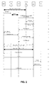
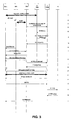
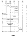
- FiGs. 2 to 4 are timing diagrams illustrating a call flows in communication systems, wherein the S-PDSN and the T-PDSN have similar capability, but are not able to fully negotiate handoff.
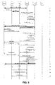
- FIG. 5 is a timing diagram illustrating a call flow in a communication system, wherein the S-PDSN and the T-PDSN have similar capability, wherein one of the service instances is dormant.
- FIG. 6 is a timing diagram illustrating a call flow in a communication system, wherein the Source-PDSN (S-PDSN) and the Target-PDSN (T-PDSN) have similar capability, wherein the Radio Network (RN) triggers various Point-to-Point (PPP) connections to effect handoff.
- S-PDSN Source-PDSN
- T-PDSN Target-PDSN
- RN Radio Network
- FIG. 7 is a timing diagram illustrating call flow in a communication system, wherein the Target-Radio Network (T-RN) does not support multiple service instances.
- T-RN Target-Radio Network
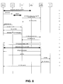
- FIGs. 8 and 9 are timing diagrams illustrating call flow in a communication system, wherein the T-PDSN does not support multiple service instances.
- FIG. 10 is a block diagram of the communication system supporting IP data transmissions.
- FIG. 11 illustrates communication links involved in a handoff example for a system wherein the S-PDSN and the T-PDSN have similar capability.
- FIG. 12 illustrates communication links involved in a handoff example for a system wherein the S-PDSN and the T-PDSN have different capabilities.
- FIG. 13 illustrates communication links involved in a handoff example for a system wherein the Source-Radio Network (S-RN) and the Target-Radio Network (T-RN) have different capabilities.
- S-RN Source-Radio Network
- T-RN Target-Radio Network
- the following discussion develops the exemplary embodiments by first presenting a network implementing mobile IP to communicate data to and from a mobile node. Then a spread-spectrum wireless communication system is discussed. Next, the mobile IP network is shown implemented in the wireless communication system. The messages are illustrated that register a mobile node with a home agent thereby enabling IP data to be sent to and from the mobile node. Finally, methods for reclaiming resources at the home agent are explained.
- the exemplary embodiment is provided as an exemplar throughout this discussion; however, alternate embodiments may incorporate various aspects without departing from the scope of the present invention. Specifically, the various embodiments are applicable to a data processing system, a wireless communication system, a mobile IP network and any other system desiring efficient use and management of resources.
- the exemplary embodiment employs a spread-spectrum wireless communication system.
- Wireless communication systems are widely deployed to provide various types of communication such as voice, data, and so on. These systems may be based on Code Division-Multiple Access (CDMA), Time Division Multiple Access (TDMA), or some other modulation techniques.
- CDMA Code Division-Multiple Access
- TDMA Time Division Multiple Access
- a CDMA system provides certain advantages over other types of systems, including increased system capacity.
- a system may be designed to support one or more standards such as the "TIA/EIA/IS-95-B Mobile Station-Base Station Compatibility Standard for Dual-Mode Wideband Spread Spectrum Cellular System” referred to herein as the IS-95 standard, the standard offered by a consortium named “3rd Generation Partnership Project” referred to herein as 3GPP, and embodied in a set of documents including Document Nos.
- standards such as the "TIA/EIA/IS-95-B Mobile Station-Base Station Compatibility Standard for Dual-Mode Wideband Spread Spectrum Cellular System” referred to herein as the IS-95 standard, the standard offered by a consortium named “3rd Generation Partnership Project” referred to herein as 3GPP, and embodied in a set of documents including Document Nos.
- 3GPP2 3rd Generation Partnership Project 2
- TR-45.5 referred to herein as the cdma2000 standard, formerly called IS-2000 MC.
- the standards cited hereinabove are hereby expressly incorporated herein by reference.
- Each standard specifically defines the processing of data for transmission from base station to mobile, and vice versa.
- the following discussion considers a spread-spectrum communication system consistent with the CDMA2000 standard of protocols. Alternate embodiments may incorporate another standard.
- a communication system 100 is shown in FIG. 10 .
- the communication system 100 includes both wireless portions and Internet Protocol (IP) portions.
- IP Internet Protocol
- a Mobile Station 120 operating within communication system 100 is first in communication with a Source-Radio Network (S-RN) 108, wherein the term source refers to the RN as being the original serving network.
- S-RN Source-Radio Network
- the MS 120 has established a Service Instance (SI) with S-RN.
- SI Service Instance
- a service instance refers to a link associated with a service option.
- a service option may be a packet data link, a Voice over IP (VoIP) link, etc.
- VoIP Voice over IP
- the S-RN has established an A-10 connection with the Source-PDSN (S-PDSN) 104 via an IP Network 106.
- the A-10 connection is associated with the SI.
- the various elements of the system such as the S-PDSN 104, the S-RN 108, and the MS 120, may support only one SI, or may support multiple SI.
- various elements may support only a single SI while other elements support multiple SI.
- the later system configurations may lead to incompatibilities in the capabilities of the various elements, and thus effect handoff.
- the S-PDSN 102 is also in communication with an IP Network 130. Operation of system 100 may be as specified in the cdma2000 Wireless IP Network Standard.
- the MS 120 is mobile and may move into an area supported by a Target-RN (T-RN) 118. As the MS 120 is able to communicate with T-RN 118, handoff may proceed from S-RN 108 to T-RN 118. Once handoff of the wireless portion of the communication system 100 is completed, the packet data portion of the system 100 must set up the various PPP links, such as an A-10 connection from T-PDSN 114 to T-RN through IP Network 116. As discussed hereinabove, various scenarios are possible for the configuration and handoff processing of a system, such as system 100.
- the S-PDSN 104 and the T-PDSN 114 have a same capability with respect to handling Service Instances (SI).
- SI Service Instances
- multiple SI links may be established to both S-PDSN 104 and T-PDSN 114.
- one link is designated as a main link, or PPP link.
- the main link is used for setting up the PPP link and is also used for signaling associated with the multiple links.
- the main link is the link on which the primary packet service instance is connected. It is the service instance that is first negotiated when establishing the packet service. This means that the initial PPP negotiation takes place over this service instance.
- the primary packet service instance has a direct relation to the packet data session itself.
- MAIN SI MAIN SI
- auxiliary or secondary links identified as "AUX SI.”
- Each link is further defined by an A-1 0 connection to a PDSN.
- the infrastructure elements, S-PDSN 104 and T-PDSN 114 successfully handoff the communication with MS 120.
- the handoff is effected without passing responsibility on to MS 120.
- MS 120 is not required to initiate a new communication at the target network, such as may have been required if handoff were not successful and the target network would tear down the main SI and auxiliary SI.
- S-PDSN 104 provides T-PDSN 114 with the necessary information to establish communication with MS 120. Note that even though handoff is completed within the radio network or wireless portion of the system, the packet data portion or IP portion requires additional information to set up the various connections required. For example, the T-PDSN 114 needs to know which SI is the main SI, as the T-PDSN 114 needs to negotiate PPP set up on the main SI.
- FIG. 1 illustrates a call flow associated with fast handoff of one embodiment.
- FIG. 1 illustrates a successful case when the handoff happens between the same revisions of two PDSNs, e.g. both PDSN are implementing IS-835-B procedures.
- P-P PDSN to PDSN
- T-PDSN Target-PDSN
- S-PDSN Serving-PDSN
- P-P connections can not be established correctly, the normal hard handoff should occur without tearing the traffic channel.
- the target PDSN does not know the PPP service instance (main service instance), therefore, it can not initiate PPP negotiation on the correct R-P connection.
- Each labeled step of call flow of FIG. 1 is detailed as follows:
- S-PDSN and T-PDSN share same capabilities, however, they fail to negotiate the handoff of the multiple SI links.
- the S-PDSN is able to send a message indicating which of the links is the main link.
- the T-PDSN then takes responsibility for the handoff and sets up connections for the MS.
- the serving PDSN desires to send PPP service instance indication to the target PDSN in P-P RRP during the period of the signaling exchange to setup P-P connections. This information may be sent regardless of whether P-P connections are setup successfully or unsuccessfully. In the case that the P-P connections establishment fails or later some disconnection between T-PDSN and S-PDSN is detected, the target PDSN uses this information to trigger the PPP negotiation on the correct R-P connection.
- FIG. 2 illustrates this type of call flow. Each labeled step of call flow of FIG. 1 is detailed as follows:
- the target PDSN If the target PDSN can not receive the P-P RRP correctly after several retransmissions, the target PDSN should indicate to the target RN in A11 RRP that the operation is failed. In response, the T-RN will release the traffic channel. In this third scenario, the target PDSN cannot receive any messages from the serving PDSN, and therefore, the MS releases the traffic channel. The responsibility for handoff falls to the MS, as the MS initiates the communications, i.e., sessions, with the target network. Note that for a given system, the radio network level handoff may have been completed successfully, however, the packet data network level must also accomplish a handoff from the S-PDSN to the T-PDSN.
- FIG. 3 wherein each labeled step is described as follows:
- the target network, and T-PDSN specifically is unable to receive handoff information from the source network, and S-PDSN specifically.
- the target network attempts to set up the PPP connections via all of the SI links.
- the T-PDSN since the T-PDSN does not know which SI link to use for setting up the PPP connection, it sends the request information on all links.
- the T-PDSN sends a Link Control Protocol (LCP) registration message on all SI links.
- LCP Link Control Protocol
- the MS desires two links, one for packet data, such as web accesses, and one for Voice over IP (VoIP).
- the target PDSN can still indicate the target RN in A11 RRP that the operation is successful. And then the T-PDSN sends LCP Configure Request on all R-P connections to trigger the PPP negotiation.
- the PPP negotiation will occur over the PPP service instance.
- LCP Configure Request is treated as packet data payload (for example, for Voice over IP, it is treated as RTP payload), therefore, it will be either discarded if the format is not correct or be passed to the application and is treated as error.
- MCFTP can be used for setup the secondary packet service instance(s).
- the MS again desires multiple Sis, specifically two, however, the main PPP SI is dormant. While the main SI is dormant, the corresponding A10 is still in place.
- the MS is responsible to trigger Dormant Handoff after detecting the Packet Zone ID (PZID) is changed upon receiving In-traffic System Parameter Message (ISPM) from the traffic channel.
- PZID Packet Zone ID
- ISPM In-traffic System Parameter Message
- the dormant service instance has to be transitioned to the Active state.
- the dormant service may not be required, and therefore making it active to accomplish handoff is a waste of resources.
- Each labeled step is illustrated in FIG. 5 , and described as follows:
- S-PDSN when the P-P Connection is successfully established for secondary Service Instances with S-PDSN, S-PDSN is responsible to trigger the set up of P-P connection for dormant PPP service instance or other dormant service instances as the S-PDSN has knowledge as to which service is in Dormant Mode.
- the T-PDSN may start to trigger the set up of A10 connections for the dormant service instances.
- the serving network When the serving network has capability to support multiple Sls, and the target network does not, the system must determine which one to terminate and how to effect such termination. For example, when the handoff occurs from low revision PDSN (IS-835 Release A or lower) to high revision PDSN (IS-835 Release B or higher), there are no problems because IS-835-A PDSN can only support one packet data service instance. In this case, after handoff to the target PDSN, the secondary service instances can be setup.
- the serving network has capability for only a single SI, as specified in IS-95.
- cdma2000 Release 0 specifies support for a single SI. Starting from cdma2000 Release A, multiple SI are specified to be supported, and the target has capability for multiple Sls, the responsibility is on the MS to initiate the additional Sls with the target network after handoff.
- a seventh scenario is illustrated in FIG. 7 and with respect to FIG. 13 , wherein the target radio network, T-RN, is not able to support multiple Sls.
- the serving radio network, S-RN knows that the target network cannot support sessions that are active in the serving network prior to handoff. For example, when the handoff occurs from high revision PDSN (IS-835 Release B or higher) to low revision PDSN (IS-835 Release A or lower), if there are secondary service instances established, how to handle these multiple service instances becomes a problem. In this situation, because the serving RN knows the target RN cannot support concurrent services (multiple R-P connections), the serving RN only performs handoff for the main service instance (PPP Service instance) to T-RN. The MS may also indicate to the user that the secondary service instances are dropped because of roaming to a lower revisions area.
- PPP Service instance main service instance
- FIG. 13 illustrates the system 100 including a T-PDSN 144, which may be capable of multiple Sls, but is illustrated supporting the one SI allowed by T-RN 148.
- T-PDSN 144 After successful handoff to the target network, the main SI is established with T-RN 148 and the associated A10 connection is established between T-RN 148 and T-PDSN 144.
- the target RN can support concurrent service, i.e., multiple service instances, but the corresponding T-PDSN can not support multiple service instances.
- the T-RN sends an A11 RRQ to request for bicasting upon handoff is requested by the S-RN. Since the old revision of T-PDSN doesn't support P-P connection and bicasting establishment, the T-PDSN will send A11 RRP to indicate failure. In this case, T-RN doesn't know which is PPP service instance, the T-RN has to release traffic channel. The MS should indicate the user call is dropped because of roaming to the low revision area. If needed, the MS will start to set up SO33 from the beginning.
- Each of the labeled step of FIG. 8 is described as follows:
- FIG. 12 illustrates the system 100 including a T-PDSN 134 which is not capable to support multiple sessions. Therefore, even though, the T-RN 118 may support multiple Sls, only the main SI has a corresponding A10 connection established with T-PDSN 134.
- a ninth scenario illustrated in FIG. 9 , during the handoff between T-RN and S-RN, the PPP service instance information is also exchanged. Therefore, when The T-RN receives failure indication from T-PDSN, the T-RN only release the secondary service instance and keep the PPP service instance connected.
- DSP digital signal processor
- ASIC application specific integrated circuit
- FPGA field programmable gate array
- a general purpose processor may be a microprocessor, but in the alternative, the processor may be any conventional processor, controller, microcontroller, or state machine.
- a processor may also be implemented as a combination of computing devices, e.g., a combination of a DSP and a microprocessor, a plurality of microprocessors, one or more microprocessors in conjunction with a DSP core, or any other such configuration.
- a software module may reside in RAM memory, flash memory, ROM memory, EPROM memory, EEPROM memory, registers, hard disk, a removable disk, a CD-ROM, or any other form of storage medium known in the art.
- An exemplary storage medium is coupled to the processor such the processor can read information from, and write information to, the storage medium.
- the storage medium may be integral to the processor.
- the processor and the storage medium may reside in an ASIC.
- the ASIC may reside in a user terminal.
- the processor and the storage medium may reside as discrete components in a user terminal.
- a method for handoff in a communication system comprising: establishing a main link and a secondary link between a mobile unit a serving packet data service node via a serving radio network; initiating a handoff from the serving radio network to a target radio network; and sending a message to a target packet data service node identifying the main link.
- the method may further comprise:
- the method may further comprise: sending a Point-to-Point Protocol (PPP) configuration request from the target packet data service node to the mobile unit.
- PPP Point-to-Point Protocol
- the main link may be associated with a first service instance, and the secondary link is associated with a second service instance.
- the second service instance may be a Voice over Internet Protocol service.
- the serving packet data service node and the target packet data service node may incorporate compatible protocols.
- the compatible protocols may be a same protocol.
- the initiating may further comprise:
- the method may further comprise: sending a handoff message form the service radio network to the target radio network.
- the pilot report may identify a pilot signal strength.
- the message may be a reply to a registration request.
- a method for handoff in a communication system comprising: initiating handoff from a serving radio network to a target radio network; receiving a registration request from a target radio network; sending a link initiation message to a mobile unit on a first link via the target radio network, the first link associated with a first service instance; and sending the link initiation message to the mobile unit on a second link via the target radio network, the second link associated with a second service instance.
- the first link may be a Point-to-Point Protocol (PPP) connection.
- PPP Point-to-Point Protocol
- the second link may be an auxiliary link for Voice over Internet Protocol.
- the method may further comprise: requesting registration from a serving packet data service node.
- a method for handoff in a communication system comprising:
- a method for handoff in a communication system comprising: initiating a handoff from a serving radio network to a target radio network, the serving radio network coupled to a serving packet data service node adapted to support multiple service instances, the target radio network coupled to a target packet data service node adapted to support one service instance; sending main link information of the serving radio network to the target radio network; and performing handoff to the target radio network.
- an apparatus in a communication system, the apparatus comprising: means for establishing a main link and a secondary link between a mobile unit a serving packet data service node via a serving radio network; means for initiating a handoff from the serving radio network to a target radio network; and means for sending a message to a target packet data service node identifying the main link.
- an apparatus in a communication system, the apparatus comprising: means for initiating handoff from a serving radio network to a target radio network; means for receiving a registration request from a target radio network; means for sending a link initiation message to a mobile unit on a first link via the target radio network, the first link associated with a first service instance; and means for sending the link initiation message to the mobile unit on a second link via the target radio network, the second link associated with a second service instance.
- an apparatus in a communication system, the apparatus comprising: means for initiating a handoff from a serving radio network to a target radio network, the serving radio network adapted to support multiple service instances, the target radio network adapted to support one service instance; means for terminating a secondary link to the serving radio network; means for sending main link information of the serving radio network to the target radio network; and means for performing handoff to the target radio network.
- a packet data service node in a communication system, the packet data service node adapted to: establish a main link and a secondary link with a mobile unit via a serving radio network; initiate a handoff to a target radio network; and send a message to a target packet data service node identifying the main link.
Abstract
Description
- The present invention relates to wireless communication systems generally and specifically, to methods and apparatus for handoff for a packet data service
- There is an increasing demand for packetized data services over wireless communication systems. As traditional wireless communication systems are designed for voice communications, the extension to support data services introduces many challenges. Specifically, the problems exist during handoff involving a Point-to-Point Protocol (PPP) communication of data packets. As systems upgrade components, compatibility issues between components may hinder operation of the system. Further, there is a desire to remove handoff responsibility from the mobile station and provide smart handoff by the infrastructure elements.
- There is a need, therefore, for fast, accurate handoff between Packet Data Service Nodes (PDSNs) and other infrastructure elements in a wireless communication system.
-
FIG. 1 is a timing diagram illustrating a call flow in a communication system, wherein the Source-PDSN (S-PDSN) and the Target-PDSN (T-PDSN) have similar capability. -
FiGs. 2 to 4 are timing diagrams illustrating a call flows in communication systems, wherein the S-PDSN and the T-PDSN have similar capability, but are not able to fully negotiate handoff. -
FIG. 5 is a timing diagram illustrating a call flow in a communication system, wherein the S-PDSN and the T-PDSN have similar capability, wherein one of the service instances is dormant. -
FIG. 6 is a timing diagram illustrating a call flow in a communication system, wherein the Source-PDSN (S-PDSN) and the Target-PDSN (T-PDSN) have similar capability, wherein the Radio Network (RN) triggers various Point-to-Point (PPP) connections to effect handoff. -
FIG. 7 is a timing diagram illustrating call flow in a communication system, wherein the Target-Radio Network (T-RN) does not support multiple service instances. -
FIGs. 8 and9 are timing diagrams illustrating call flow in a communication system, wherein the T-PDSN does not support multiple service instances. -
FIG. 10 is a block diagram of the communication system supporting IP data transmissions. -
FIG. 11 illustrates communication links involved in a handoff example for a system wherein the S-PDSN and the T-PDSN have similar capability. -
FIG. 12 illustrates communication links involved in a handoff example for a system wherein the S-PDSN and the T-PDSN have different capabilities. -
FIG. 13 illustrates communication links involved in a handoff example for a system wherein the Source-Radio Network (S-RN) and the Target-Radio Network (T-RN) have different capabilities. - The word "exemplary" is used exclusively herein to mean "serving as an example, instance, or illustration." Any embodiment described herein as "exemplary" is not necessarily to be construed as preferred or advantageous over other embodiments. While the various aspects of the embodiments are presented in drawings, the drawings are not necessarily drawn to scale unless specifically indicated.
- The following discussion develops the exemplary embodiments by first presenting a network implementing mobile IP to communicate data to and from a mobile node. Then a spread-spectrum wireless communication system is discussed. Next, the mobile IP network is shown implemented in the wireless communication system. The messages are illustrated that register a mobile node with a home agent thereby enabling IP data to be sent to and from the mobile node. Finally, methods for reclaiming resources at the home agent are explained.
- Note that the exemplary embodiment is provided as an exemplar throughout this discussion; however, alternate embodiments may incorporate various aspects without departing from the scope of the present invention. Specifically, the various embodiments are applicable to a data processing system, a wireless communication system, a mobile IP network and any other system desiring efficient use and management of resources.
- The exemplary embodiment employs a spread-spectrum wireless communication system. Wireless communication systems are widely deployed to provide various types of communication such as voice, data, and so on. These systems may be based on Code Division-Multiple Access (CDMA), Time Division Multiple Access (TDMA), or some other modulation techniques. A CDMA system provides certain advantages over other types of systems, including increased system capacity.
- A system may be designed to support one or more standards such as the "TIA/EIA/IS-95-B Mobile Station-Base Station Compatibility Standard for Dual-Mode Wideband Spread Spectrum Cellular System" referred to herein as the IS-95 standard, the standard offered by a consortium named "3rd Generation Partnership Project" referred to herein as 3GPP, and embodied in a set of documents including Document Nos. 3G TS 25.211, 3G TS 25.212, 3G TS 25.213, and 3G TS 25.214, 3G TS 25.302, referred to herein as the W-CDMA standard, the standard offered by a consortium named "3rd Generation Partnership Project 2" referred to herein as 3GPP2, and TR-45.5 referred to herein as the cdma2000 standard, formerly called IS-2000 MC. The standards cited hereinabove are hereby expressly incorporated herein by reference.
- Each standard specifically defines the processing of data for transmission from base station to mobile, and vice versa. As an exemplary embodiment the following discussion considers a spread-spectrum communication system consistent with the CDMA2000 standard of protocols. Alternate embodiments may incorporate another standard.
- A
communication system 100 according to one embodiment is shown inFIG. 10 . Thecommunication system 100 includes both wireless portions and Internet Protocol (IP) portions. The terminology used to describe the various elements of the system 200 is intended to facilitate understanding of the handoff processes described herein. A MobileStation 120 operating withincommunication system 100 is first in communication with a Source-Radio Network (S-RN) 108, wherein the term source refers to the RN as being the original serving network. The MS 120 has established a Service Instance (SI) with S-RN. A service instance refers to a link associated with a service option. For example, a service option may be a packet data link, a Voice over IP (VoIP) link, etc. The S-RN has established an A-10 connection with the Source-PDSN (S-PDSN) 104 via an IP Network 106. The A-10 connection is associated with the SI. Note that the various elements of the system, such as the S-PDSN 104, the S-RN 108, and the MS 120, may support only one SI, or may support multiple SI. Also, within a given system, such assystem 100, various elements may support only a single SI while other elements support multiple SI. The later system configurations may lead to incompatibilities in the capabilities of the various elements, and thus effect handoff. The S-PDSN 102 is also in communication with anIP Network 130. Operation ofsystem 100 may be as specified in the cdma2000 Wireless IP Network Standard. - The MS 120 is mobile and may move into an area supported by a Target-RN (T-RN) 118. As the
MS 120 is able to communicate with T-RN 118, handoff may proceed from S-RN 108 to T-RN 118. Once handoff of the wireless portion of thecommunication system 100 is completed, the packet data portion of thesystem 100 must set up the various PPP links, such as an A-10 connection from T-PDSN 114 to T-RN throughIP Network 116. As discussed hereinabove, various scenarios are possible for the configuration and handoff processing of a system, such assystem 100. - In a first scenario, illustrated in
FIG. 1 and with reference toFIG. 11 , the S-PDSN 104 and the T-PDSN 114 have a same capability with respect to handling Service Instances (SI). As illustrated inFIG. 11 , multiple SI links may be established to both S-PDSN 104 and T-PDSN 114. For multiple SI links, one link is designated as a main link, or PPP link. The main link is used for setting up the PPP link and is also used for signaling associated with the multiple links. The main link is the link on which the primary packet service instance is connected. It is the service instance that is first negotiated when establishing the packet service. This means that the initial PPP negotiation takes place over this service instance. The primary packet service instance has a direct relation to the packet data session itself. This means that whenever there is a packet data session, there's a primary packet service instance connected to it. The main link is identified as "MAIN SI." Additional links are referred to as auxiliary or secondary links, identified as "AUX SI." Each link is further defined by anA-1 0 connection to a PDSN. - In the call flow scenario of
FIG. 1 , the infrastructure elements, S-PDSN 104 and T-PDSN 114 successfully handoff the communication withMS 120. The handoff is effected without passing responsibility on toMS 120. In other words,MS 120 is not required to initiate a new communication at the target network, such as may have been required if handoff were not successful and the target network would tear down the main SI and auxiliary SI. As inFIG. 1 , S-PDSN 104 provides T-PDSN 114 with the necessary information to establish communication withMS 120. Note that even though handoff is completed within the radio network or wireless portion of the system, the packet data portion or IP portion requires additional information to set up the various connections required. For example, the T-PDSN 114 needs to know which SI is the main SI, as the T-PDSN 114 needs to negotiate PPP set up on the main SI. -
FIG. 1 illustrates a call flow associated with fast handoff of one embodiment.FIG. 1 illustrates a successful case when the handoff happens between the same revisions of two PDSNs, e.g. both PDSN are implementing IS-835-B procedures. In this case, there are PDSN to PDSN (P-P) connections established successfully between the Target-PDSN (T-PDSN) and the Serving-PDSN (S-PDSN). In the situation that P-P connections can not be established correctly, the normal hard handoff should occur without tearing the traffic channel. However, if multiple service instances exist (for example, voice over IP), the target PDSN does not know the PPP service instance (main service instance), therefore, it can not initiate PPP negotiation on the correct R-P connection. Each labeled step of call flow ofFIG. 1 is detailed as follows: - A. The mobile station has one or more sessions established to the Source-Packet Data Service Node (S-PDSN) via the Source-Radio Network (S-RN). The mobile station may have multiple service instances allocated in the S-RN.
- B. The mobile station detects the pilot signal strength changes and sends pilot reports to the S-RN. At this time, the mobile still has airlink traffic channels to the S-RN and an Internet Protocol (IP) session established to the S-PDSN.
- C. S-RN sends handoff request message to Target-Radio Network (T-RN) via Mobile Switching Center (MSC) (not shown).
- D. The T-RN sends an A11 Registration Request (RRQ) to the Target-Packet Data Service Node (T-PDSN) including the s bit set to 1 and the serving P-P address attribute set to the Pi IP address of the S-PDSN. P-P refers to the connection between the S-PDSN and the T-PDSN. Pi refers to the PDSN to IP connection. The s bit indicates simultaneous binding.
- E. The T-PDSN sends a P-P RRQ including the s bit set to 1 to the S-PDSN's Pi IP address. The setting of the s bit indicates a request for a simultaneous binding at the S-PDSN.
- F. The S-PDSN replies with a P-P Registration Reply (RRP) with the reply code set to 0. The reply code indicates indicates whether the operation is successful (or failure). The
reply code 0 corresponds to a successful operation, wherein the reply code other than 0 gives a different failure reason. - G. The T-PDSN sends an A11 RRP with the reply code set to 0 to the T-RN.
- H. At this point, forward direction bearer traffic arriving at the S-PDSN is bicast to the S-RN and the T-PDSN. The T-RN may buffer the last N packets, where N is implementation dependent. Reverse direction bearer traffic traverses only the S-RN and the S-PDSN.
- I. The S-RN hands off the mobile's Service Instance(s) (Sis) to the T-RN by sending a handoff direction command to the mobile station.
- J. The mobile station handoffs to the T-RN and sends a handoff completion indication to the T-RN.
- K. Upon completion of the handoff of the Service Instances (Sls), the T-RN sends an A11 RRQ with the s bit set to 0 and including an active start airlink record to the T-PDSN.
- L. The T-PDSN sends a P-P RRQ with the s bit set to 0 and including an active start airlink record to the S-PDSN. The active start airlink record sent is the same one that was received from the T-RN.
- M. The S-PDSN replies with a P-P RRP with the reply code set to 0.
- N. The T-PDSN send an A11 RRP with the reply code set to 0 to the T-RN.
- O. At this point, forward direction bearer traffic is tunneled from the S-PDSN to the T-PDSN over the P-P interface, then switched onto the appropriate A10 session and delivered to the T-RN. Reverse direction bearer traffic is sent from the mobile to the T-RN, then over the appropriate A10 session to the T-PDSN. The T-PDSN tunnels this traffic over the P-P interface to the S-PDSN. Note that the P-P session may be periodically refreshed by the T-PDSN sending a P-P RRQ to the S-PDSN.
- P. The S-PDSN initiates a teardown of the mobile's A10/A11 session(s) to the S-RN by sending an A11 RUP to the S-RN.
- Q. The S-RN responds with an A11 RAK.
- R. The S-RN indicates that the session will be terminated by sending an A11 RRQ to the S-PDSN with the lifetime set to 0, including an active stop accounting record. Note that the accounting record will send to Authentication Authorization and Accounting (AAA) unit from Serving PDSN. AAA is not shown.
- S. The S-PDSN indicates that the session is released by sending an A11 RRP to the S-RN with the lifetime set to 0. Note that the S-PDSN does not delete the associated PPP context because it is being used by the mobile via the P-P interface.
- In a second scenario, illustrated in
FIG. 2 , again S-PDSN and T-PDSN share same capabilities, however, they fail to negotiate the handoff of the multiple SI links. The S-PDSN is able to send a message indicating which of the links is the main link. The T-PDSN then takes responsibility for the handoff and sets up connections for the MS. - Note that the serving PDSN desires to send PPP service instance indication to the target PDSN in P-P RRP during the period of the signaling exchange to setup P-P connections. This information may be sent regardless of whether P-P connections are setup successfully or unsuccessfully. In the case that the P-P connections establishment fails or later some disconnection between T-PDSN and S-PDSN is detected, the target PDSN uses this information to trigger the PPP negotiation on the correct R-P connection.
FIG. 2 illustrates this type of call flow. Each labeled step of call flow ofFIG. 1 is detailed as follows: - A. The mobile station has one or more sessions established to the S-PDSN via the S-RN. The mobile may have multiple service instances allocated in the S-RN.
- B. The mobile station detects the pilot signal strength changes and sends pilot reports to the S-RN. Note that the mobile still has airlink traffic channels to the S-RN and an IP session established to the S-PDSN.
- C. S-RN sends handoff request message to T-RN via MSC (not shown).
- D. The T-RN sends an A11 RRQ to the T-PDSN including the s bit set to 1 and the serving P-P address attribute set to the Pi IP address of the S-PDSN.
- E. The T-PDSN sends a P-P RRQ including the s bit set to 1 to the S-PDSN's Pi IP address. The setting of the s bit indicates a request for a simultaneous binding at the S-PDSN.
- F. The S-PDSN replies with a P-P RRP with a reply code other than 0, indicating that the P-P session cannot be established and indicating the PPP service instance.
- G. The T-PDSN send an A11 RRP with the reply code set to 0 to the T-RN.
- H. The S-RN hands off the mobile's service instance(s) to the T-RN by sending handoff direction command to the mobile station.
- I. The mobile station handoffs to the T-RN and sends handoff completion indication to the T-RN.
- J. Upon completion of the handoff of the service instances, the T-RN sends an A11 RRQ with the s bit set to 0 and including an active start airlink record to the T-PDSN.
- K. The T-PDSN send an A11 RRP with the reply code set to 0 to the T-RN.
- L. The T-PDSN initiates PPP negotiation with the mobile by sending it an LCP-configure-request.
- M. PPP negotiation is complete. For simple IP sessions, bearer traffic may now flow in both directions over the T-RN and T-PDSN. For MIP sessions, the behavior is as follows below.
- N. The T-PDSN sends a Mobile IP (MIP) agent advertisement to the mobile. Note that the mobile may first send a MIP agent solicitation to the T-PDSN (not shown).
- O. The mobile sends a MIP RRQ to the T-PDSN.
- P. The T-PDSN processes the MIP RRQ and then forwards it on to the HA.
- Q. If the MIP RRQ is accepted, the HA responds with a MIP RRP with a reply code of 0.
- R. The T-PDSN forwards the MIP RRP to the mobile. The mobile may now send and receive bearer data via its MIP session.
- If the target PDSN can not receive the P-P RRP correctly after several retransmissions, the target PDSN should indicate to the target RN in A11 RRP that the operation is failed. In response, the T-RN will release the traffic channel. In this third scenario, the target PDSN cannot receive any messages from the serving PDSN, and therefore, the MS releases the traffic channel. The responsibility for handoff falls to the MS, as the MS initiates the communications, i.e., sessions, with the target network. Note that for a given system, the radio network level handoff may have been completed successfully, however, the packet data network level must also accomplish a handoff from the S-PDSN to the T-PDSN. The third scenario is illustrated in
FIG. 3 , wherein each labeled step is described as follows: - A. The mobile station has one or more sessions established to the S-PDSN via the S-RN. The mobile may have multiple service instances allocated in the S-RN.
- B. The mobile station detects the pilot signal strength changes and sends pilot reports to the S-RN. Please note that the mobile still has airlink traffic channels to the S-RN and an IP session established to the S-PDSN.
- C. S-RN sends handoff request message to T-RN via MSC (not shown).
- D. The T-RN sends an A11 RRQ to the T-PDSN including the s bit set to 1 and the serving P-P address attribute set to the Pi IP address of the S-PDSN.
- E. The T-PDSN sends a P-P RRQ including the s bit set to 1 to the S-PDSN's Pi IP address. The setting of the s bit indicates a request for a simultaneous binding at the S-PDSN.
- F. The T-PDSN does not receive a P-P RRP after a configurable number of retransmissions of the P-P RRQ.
- G. The T-PDSN send an A11 RRP with the reply code set to other than 0 to the T-RN.
- H. The S-RN hands off the mobile's service instance(s) to the T-RN by sending handoff direction command to the mobile station.
- I. The mobile station handoffs to the T-RN and sends handoff completion indication to the T-RN.
- J. Upon completion of the handoff of the service instances, the T-RN release the traffic channel.
- K. The MS re-initiates the SO33 to setup the traffic channel. The SO33 refers to the data service option 33 as specified in IS707.
- L. T-RN sends A11 RRQ to set up R-P connection.
- M. T-PDSN replies with A11 RRP with result code set to '0'.
- N. The MS initiates PPP negotiation with the T-PDSN by sending it an LCP-configure-request.
- O. PPP negotiation is complete. For simple IP sessions, bearer traffic may now flow in both directions over the T-RN and T-PDSN. For MIP sessions, the behavior is as follows below.
- P. The T-PDSN sends a MIP agent advertisement to the mobile. Note that the mobile may first send a MIP agent solicitation to the T-PDSN (not shown).
- Q. The mobile sends a MIP RRQ to the T-PDSN.
- R. The T-PDSN processes the MIP RRQ and then forwards it on to the HA.
- S. If the MIP RRQ is accepted, the HA responds with a MIP RRP with a reply code of O.
- T. The T-PDSN forwards the MIP RRP to the mobile. The mobile may now send and receive bearer data via its MIP session.
- In a fourth scenario, the target network, and T-PDSN specifically, is unable to receive handoff information from the source network, and S-PDSN specifically. The target network attempts to set up the PPP connections via all of the SI links. In other words, since the T-PDSN does not know which SI link to use for setting up the PPP connection, it sends the request information on all links. In this case, the T-PDSN sends a Link Control Protocol (LCP) registration message on all SI links. In the present example, the MS desires two links, one for packet data, such as web accesses, and one for Voice over IP (VoIP). The target PDSN can still indicate the target RN in A11 RRP that the operation is successful. And then the T-PDSN sends LCP Configure Request on all R-P connections to trigger the PPP negotiation. The PPP negotiation will occur over the PPP service instance.
- For the secondary packet service instance(s), LCP Configure Request is treated as packet data payload (for example, for Voice over IP, it is treated as RTP payload), therefore, it will be either discarded if the format is not correct or be passed to the application and is treated as error. After PPP session is setup, MCFTP can be used for setup the secondary packet service instance(s). Each labeled step in the call flow of
FIG 4 is described as follows: - A. The mobile station has one or more sessions established to the S-PDSN via the S-RN. The mobile may have multiple service instances allocated in the S-RN.
- B. The mobile station detects the pilot signal strength changes and sends pilot reports to the S-RN. Please note that the mobile still has airlink traffic channels to the S-RN and an IP session established to the S-PDSN.
- C. S-RN sends handoff request message to T-RN via MSC (not shown here).
- D. The T-RN sends an A11 RRQ to the T-PDSN including the s bit set to 1 and the serving P-P address attribute set to the Pi IP address of the S-PDSN.
- E. The T-PDSN sends a P-P RRQ including the s bit set to 1 to the S-PDSN's Pi IP address. The setting of the s bit indicates a request for a simultaneous binding at the S-PDSN.
- F. The T-PDSN does not receive a P-P RRP after a configurable number of retransmissions of the P-P RRQ.
- G. The T-PDSN sends an A11 RRP with the reply code set to 0 to the T-RN.
- H. The S-RN hands off the mobile's service instance(s) to the T-RN by sending handoff direction command to the mobile station.
- I. The mobile station handoffs to the T-RN and sends handoff completion indication to the T-RN.
- J. Upon completion of the handoff of the service instances, the T-RN sends A11 RRQ to T-PDSN.
- K. T-PDSN replies with A11 RRP.
- L. T-PDSN sends LCP Configure Request on all service instances.
- M. The PPP negotiation only occurs over PPP service instance.
- N. MCFTP sent over PPP service instance is used for setup flow treatment and channel treatment for secondary service instance(s).
- O. For simple IP sessions, bearer traffic may now flow in both directions over the T-RN and T-PDSN. For MIP sessions, the behavior is as follows below.
- P. The T-PDSN sends a MIP agent advertisement to the mobile. Note that the mobile may first send a MIP agent solicitation to the T-PDSN (not shown).
- Q. The mobile sends a MIP RRQ to the T-PDSN.
- R. The T-PDSN processes the MIP RRQ and then forwards it on to the HA.
- S. If the MIP RRQ is accepted, the HA responds with a MIP RRP with a reply code of 0.
- T. The T-PDSN forwards the MIP RRP to the mobile. The mobile may now send and receive bearer data via its MIP session.
- In a fifth scenario, illustrated in
FIG. 5 , the MS again desires multiple Sis, specifically two, however, the main PPP SI is dormant. While the main SI is dormant, the corresponding A10 is still in place. For the Dormant Service Instance, the MS is responsible to trigger Dormant Handoff after detecting the Packet Zone ID (PZID) is changed upon receiving In-traffic System Parameter Message (ISPM) from the traffic channel. The PZID identifies the packet data network supporting the MS. There are two problems with this scenario. First, if the MS fails to receive the ISPM, the call is dropped as there is no A10 and no P-P connection for the PPP Service Instance. Second, the dormant service instance has to be transitioned to the Active state. The dormant service may not be required, and therefore making it active to accomplish handoff is a waste of resources. Each labeled step is illustrated inFIG. 5 , and described as follows: - A. The mobile station has multiple sessions established to the S-PDSN via the S-RN. The mobile station has multiple service instance(s) in Dormant (for example, PPP service Instance) and has multiple service instances active and allocated in the S-RN.
- B. The mobile station detects the pilot signal strength changes and sends pilot reports to the S-RN. At this time, the mobile still has airlink traffic channels to the S-RN and an IP session established to the S-PDSN.
- C. S-RN sends handoff request message to T-RN via MSC (not shown here).
- D. The T-RN sends an A11 RRQ to the T-PDSN including the s bit set to 1 and the serving P-P address attribute set to the Pi IP address of the S-PDSN.
- E. The T-PDSN sends a P-P RRQ including the s bit set to 1 to the S-PDSN's Pi IP address. The setting of the s bit indicates a request for a simultaneous binding at the S-PDSN.
- F. The S-PDSN replies with a P-P RRP with the reply code set to 0.
- G. The T-PDSN sends an A11 RRP with the reply code set to 0 to the T-RN.
- H. At this point, forward direction bearer traffic arriving at the S-PDSN is bicast to the S-RN and the T-PDSN for the Active Service Instance. The T-RN may buffer the last N packets, where N is implementation dependent. Reverse direction bearer traffic traverses only the S-RN and the S-PDSN.
- I. The S-RN hands off the mobile's service instance(s) to the T-RN by sending handoff direction command to the mobile station.
- J. The mobile station handoffs to the T-RN and sends handoff completion indication to the T-RN.
- K. Upon completion of the handoff of the service instances, the T-RN sends an A11 RRQ with the s bit set to 0 and including an active start airlink record to the T-PDSN.
- L. The T-PDSN sends a P-P RRQ with the s bit set to 0 and including an active start airlink record to the S-PDSN. The active start airlink record sent is the same one that was received from the T-RN.
- M. The S-PDSN replies with a P-P RRP with the reply code set to 0.
- N. The T-PDSN send an A11 RRP with the reply code set to 0 to the T-RN.
- O. The T-RN sends system information via In-Traffic System Parameter Message (ISPM) including the new Packet Zone ID (PZID).
- P. The MS detects PZID is changed, the MS will send Ehanced Origination Message (EOM) to set up SO33 which is main service instance as an example.
- Q. The T-RN sends A11 RRQ to setup A10 connection.
- R. The T-PDSN sends P-P RRQ to setup P-P connection.
- S. The S-PDSN replies with P-P RRP.
- T. The T-PDSN replies with A11 RRP.
- U. T-RN sends service connect to the MS to connect PPP service instance.
- V. The MS replies with service connect completion.
- W. Upon the PPP service instance is connected, T-RN sends A11 RRQ to start accounting record.
- X. The T-PDSN sends P-P RRQ to S-PDSN.
- Y. The S-PDSN replies with P-P RRP.
- Z. T-PDSN replies with A11 RRP.
- AA. At this point, forward direction bearer traffic for both PPP service instances and Secondary Service Instance are tunneled from the S-PDSN to the T-PDSN over the P-P interface, then switched onto the appropriate A10 session and delivered to the T-RN. Reverse direction bearer traffic is sent from the mobile to the T-RN, then over the appropriate A10 session to the T-PDSN. The T-PDSN tunnels this traffic over the P-P interface to the S-PDSN. Note that the P-P session may be periodically refreshed by the T-PDSN sending a P-P RRQ to the S-PDSN.
- BB. The S-PDSN initiates a teardown of the mobile's A10/A11 session(s) to the S-RN by sending an A11 RUP to the S-RN.
- CC. The S-RN responds with an A11 RAK.
- DD. The S-RN indicates that the session will be terminated by sending an A11 RRQ to the S-PDSN with the lifetime set to 0, including an active stop accounting record.
- EE. The S-PDSN indicates that the session is released by sending an A11 RRP to the S-RN with the lifetime set to 0. Note that the S-PDSN does not delete the associated PPP context because it is being used by the mobile via the P-P interface.
- In a sixth scenario, illustrated in
FIG. 6 , when the P-P Connection is successfully established for secondary Service Instances with S-PDSN, S-PDSN is responsible to trigger the set up of P-P connection for dormant PPP service instance or other dormant service instances as the S-PDSN has knowledge as to which service is in Dormant Mode. The T-PDSN may start to trigger the set up of A10 connections for the dormant service instances. The labeled steps of the call flow ofFIG. 6 are described as follows: - A. The mobile station has multiple sessions established to the S-PDSN via the S-RN. The mobile station has multiple service instance(s) in Dormant (for example, PPP service Instance) and has multiple service instances active and allocated in the S-RN.
- B. The mobile station detects the pilot signal strength changes and sends pilot reports to the S-RN. At this time, the mobile still has airlink traffic channels to the S-RN and an IP session established to the S-PDSN.
- C. S-RN sends handoff request message to T-RN via MSC (not shown here).
- D. The T-RN sends an A11 RRQ to the T-PDSN including the s bit set to 1 and the serving P-P address attribute set to the Pi IP address of the S-PDSN.
- E. The T-PDSN sends a P-P RRQ including the s bit set to 1 to the S-PDSN's Pi IP address. The setting of the s bit indicates a request for a simultaneous binding at the S-PDSN.
- F. The S-PDSN replies with a P-P RRP with the reply code set to 0.
- G. The T-PDSN sends an A11 RRP with the reply code set to 0 to the T-RN.
- H. Because S-PDSN knows PPP service instance is in Dormant mode, S-PDSN will sends P-P RRQ to T-PDSN to set up P-P connection.
- I. T-PDSN replies with P-P RRP with result code set to '0'.
There are two options here.
Option 1: - J. The T-PDSN sends A11 RUP to T-RN to request for establishing R-P connection for PPP service Instance.
- K. The T-RN replies with A11 RAK.
- L. Then the T-RN sends A11 RRQ to set up A10 connection.
- M. T-PDSN replies with A11 RRP with code set to '0'.
Option 2: - N. The T-PDSN sends A11 RRQ to establish R-P connection for PPP service Instance.
- O. The T-RN replies with A11 RRP with code set to '0'.
- P. At this point, forward direction bearer traffic arriving at the S-PDSN is bicast to the S-RN and the T-PDSN for both PPP Service Instance and Secondary Service Instance. The T-RN may buffer the last N packets, where N is implementation dependent. Reverse direction bearer traffic traverses only the S-RN and the S-PDSN.
- Q. The S-RN hands off the mobile's service instance(s) to the T-RN by sending handoff direction command to the mobile station.
- R. The mobile station handoffs to the T-RN and sends handoff completion indication to the T-RN.
- S. Upon completion of the handoff of the service instances, the T-RN sends an A11 RRQ with the s bit set to 0 and including an active start airlink record to the T-PDSN.
- T. The T-PDSN sends a P-P RRQ with the s bit set to 0 and including an active start airlink record to the S-PDSN. The active start airlink record sent is the same one that was received from the T-RN.
- U. The S-PDSN replies with a P-P RRP with the reply code set to 0.
- V. The T-PDSN send an A11 RRP with the reply code set to 0 to the T-RN.
- W. At this point, forward direction bearer traffic for both PPP service instances and Secondary Service Instance are tunneled from the S-PDSN to the T-PDSN over the P-P interface, then switched onto the appropriate A10 session and delivered to the T-RN. Reverse direction bearer traffic is sent from the mobile to the T-RN, then over the appropriate A10 session to the T-PDSN. The T-PDSN tunnels this traffic over the P-P interface to the S-PDSN. Note that the P-P session may be periodically refreshed by the T-PDSN sending a P-P RRQ to the S-PDSN.
- X. The S-PDSN initiates a teardown of the mobile's A10/A11 session(s) to the S-RN by sending an A11 RUP to the S-RN.
- Y. The S-RN responds with an A11 RAK.
- Z. The S-RN indicates that the session will be terminated by sending an A11 RRQ to the S-PDSN with the lifetime set to 0, including an active stop accounting record.
- AA. The S-PDSN indicates that the session is released by sending an A11 RRP to the S-RN with the lifetime set to 0. Note that the S-PDSN does not delete the associated PPP context because it is being used by the mobile via the P-P interface.
- The scenarios and examples discussed hereinabove assume a same version of protocols for the serving network and the target network. In other words, these examples and scenarios assumed that the S-PDSN and the T-PDSN had similar capabilities. For example, each was able to support multiple Service Instances. Consider the situation where the packet data networks and/or the radio networks do not have similar capabilities, but rather, one is able to handle multiple Sls, while the other is not.
- When the serving network has capability to support multiple Sls, and the target network does not, the system must determine which one to terminate and how to effect such termination. For example, when the handoff occurs from low revision PDSN (IS-835 Release A or lower) to high revision PDSN (IS-835 Release B or higher), there are no problems because IS-835-A PDSN can only support one packet data service instance. In this case, after handoff to the target PDSN, the secondary service instances can be setup. When the serving network has capability for only a single SI, as specified in IS-95. Also
cdma2000 Release 0 specifies support for a single SI. Starting from cdma2000 Release A, multiple SI are specified to be supported, and the target has capability for multiple Sls, the responsibility is on the MS to initiate the additional Sls with the target network after handoff. - A seventh scenario is illustrated in
FIG. 7 and with respect toFIG. 13 , wherein the target radio network, T-RN, is not able to support multiple Sls. Note that the serving radio network, S-RN, knows that the target network cannot support sessions that are active in the serving network prior to handoff. For example, when the handoff occurs from high revision PDSN (IS-835 Release B or higher) to low revision PDSN (IS-835 Release A or lower), if there are secondary service instances established, how to handle these multiple service instances becomes a problem. In this situation, because the serving RN knows the target RN cannot support concurrent services (multiple R-P connections), the serving RN only performs handoff for the main service instance (PPP Service instance) to T-RN. The MS may also indicate to the user that the secondary service instances are dropped because of roaming to a lower revisions area. Each of the labeled steps in the call flow ofFIG. 7 is described as follows: - A. The mobile station has one or more sessions established to the S-PDSN via the S-RN. The mobile may have multiple service instances allocated in the S-RN.
- B. The mobile station detects the pilot signal strength changes and sends pilot reports to the S-RN. Please note that the mobile still has airlink traffic channels to the S-RN and an IP session established to the S-PDSN.
- C. S-RN sends handoff request message to T-RN via MSC (not shown).
- D. Because S-RN knows the T-RN cannot support concurrent service, S-RN hands off the mobile's PPP service instance to the T-RN by sending handoff direction command to the mobile station.
- E. The mobile station handoffs to the T-RN and sends handoff completion indication to the T-RN.
- F. Upon completion of the handoff of the service instances, the T-RN sends an A11 RRQ with the s bit set to 0 and including an active start airlink record to the T-PDSN.
- G. The T-PDSN send an A11 RRP with the reply code set to 0 to the T-RN.
- H. The T-PDSN initiates PPP negotiation with the mobile by sending it an LCP-configure-request.
- I. PPP negotiation is complete. For simple IP sessions, bearer traffic may now flow in both directions over the T-RN and T-PDSN. For MIP sessions, the behavior is as follows below.
- J. The T-PDSN sends a MIP agent advertisement to the mobile. Note that the mobile may first send a MIP agent solicitation to the T-PDSN (not shown).
- K. The mobile sends a MIP RRQ to the T-PDSN.
- L. The T-PDSN processes the MIP RRQ and then forwards it on to the HA.
- M. If the MIP RRQ is accepted, the HA responds with a MIP RRP with a reply code of 0.
- N. The T-PDSN forwards the MIP RRP to the mobile. The mobile may now send and receive bearer data via its MIP session.
-
FIG. 13 illustrates thesystem 100 including a T-PDSN 144, which may be capable of multiple Sls, but is illustrated supporting the one SI allowed by T-RN 148. After successful handoff to the target network, the main SI is established with T-RN 148 and the associated A10 connection is established between T-RN 148 and T-PDSN 144. - In an eight scenario, illustrated in
FIG. 8 and with respect toFIG. 12 , the target RN can support concurrent service, i.e., multiple service instances, but the corresponding T-PDSN can not support multiple service instances. As illustrated in the call flow ofFIG. 8 , the T-RN sends an A11 RRQ to request for bicasting upon handoff is requested by the S-RN. Since the old revision of T-PDSN doesn't support P-P connection and bicasting establishment, the T-PDSN will send A11 RRP to indicate failure. In this case, T-RN doesn't know which is PPP service instance, the T-RN has to release traffic channel. The MS should indicate the user call is dropped because of roaming to the low revision area. If needed, the MS will start to set up SO33 from the beginning. Each of the labeled step ofFIG. 8 is described as follows: - A. The mobile station has one or more sessions established to the S-PDSN via the S-RN. The mobile may have multiple service instances allocated in the S-RN.
- B. The mobile station detects the pilot signal strength changes and sends pilot reports to the S-RN. Please note that the mobile still has airlink traffic channels to the S-RN and an IP session established to the S-PDSN.
- C. S-RN sends handoff request message to T-RN via MSC (not shown here).
- D. The T-RN sends an A11 RRQ to the T-PDSN including the s bit set to 1 and the serving P-P address attribute set to the Pi IP address of the S-PDSN.
- E. Since the T-PDSN does not support fast P-P interface handoff, the T-PDSN sends an A11 RRP with the reply code set to other than 0 to the T-RN.
- F. The S-RN hands off the mobile's service instance(s) to the T-RN by sending handoff direction command to the mobile station.
- G. The mobile station handoffs to the T-RN and sends handoff completion indication to the T-RN.
- H. Upon completion of the handoff of the service instances, the T-RN releases the traffic channel since it doesn't know which service instance is PPP service instance.
- I. The MS re-initiates the SO33 to setup the traffic channel.
- J. T-RN sends A11 RRQ to set up R-P connection.
- K. T-PDSN replies with A11 RRP with result code set to '0'.
- L. The MS initiates PPP negotiation with the T-PDSN by sending it an LCP-configure-request.
- M. PPP negotiation is complete. For simple IP sessions, bearer traffic may now flow in both directions over the T-RN and T-PDSN. For MIP sessions, the behavior is as follows below.
- N. The T-PDSN sends a MIP agent advertisement to the mobile. Note that the mobile may first send a MIP agent solicitation to the T-PDSN (not shown).
- O. The mobile sends a MIP RRQ to the T-PDSN.
- P. The T-PDSN processes the MIP RRQ and then forwards it on to the HA.
- Q. If the MIP RRQ is accepted, the HA responds with a MIP RRP with a reply code of 0.
- R. The T-PDSN forwards the MIP RRP to the mobile. The mobile may now send and receive bearer data via its MIP session.
-
FIG. 12 illustrates thesystem 100 including a T-PDSN 134 which is not capable to support multiple sessions. Therefore, even though, the T-RN 118 may support multiple Sls, only the main SI has a corresponding A10 connection established with T-PDSN 134. - In a ninth scenario, illustrated in
FIG. 9 , during the handoff between T-RN and S-RN, the PPP service instance information is also exchanged. Therefore, when The T-RN receives failure indication from T-PDSN, the T-RN only release the secondary service instance and keep the PPP service instance connected. Each of the labeled steps of the call flow ofFIG. 9 is described as follows: - A. The mobile station has one or more sessions established to the S-PDSN via the S-RN. The mobile may have multiple service instances allocated in the S-RN.
- B. The mobile station detects the pilot signal strength changes and sends pilot reports to the S-RN. Please note that the mobile still has airlink traffic channels to the S-RN and an IP session established to the S-PDSN.
- C. S-RN sends handoff request message to T-RN via MSC (not shown here). Also the S-RN indicate the PPP service instance to T-RN.
- D. The T-RN sends an A11 RRQ to the T-PDSN including the s bit set to 1 and the serving P-P address attribute set to the Pi IP address of the S-PDSN.
- E. Since the T-PDSN does not support fast P-P interface handoff, the T-PDSN sends an A11 RRP with the reply code set to other than 0 to the T-RN.
- F. The S-RN hands off the mobile's service instance(s) to the T-RN by sending handoff direction command to the mobile station.
- G. The mobile station handoffs to the T-RN and sends handoff completion indication to the T-RN.
- H. Since the T-RN knows which service instance is PPP service instance, the T-RN sends A11 RRQ to set up R-P connection for PPP service instance.
- I. T-PDSN replies with A11 RRP with result code set to '0'.
- J. The T-RN also sends service connect to the MS to release the Secondary Service Instance and maintain the PPP Service Instance.
- K. T-PDSN will trigger the PPP negotiation by sending LCP Configure Request.
- L. PPP negotiation is complete. For simple IP sessions, bearer traffic may now flow in both directions over the T-RN and T-PDSN. For MIP sessions, the behavior is as follows below.
- M. The T-PDSN sends a MIP agent advertisement to the mobile. Note that the mobile may first send a MIP agent solicitation to the T-PDSN (not shown).
- N. The mobile sends a MIP RRQ to the T-PDSN.
- O. The T-PDSN processes the MIP RRQ and then forwards it on to the HA.
- P. If the MIP RRQ is accepted, the HA responds with a MIP RRP with a reply code of 0.
- Q. The T-PDSN forwards the MIP RRP to the mobile. The mobile may now send and receive bearer data via its MIP session.
- Those of skill in the art would understand that information and signals may be represented using any of a variety of different technologies and techniques. For example, data, instructions, commands, information, signals, bits, symbols, and chips that may be referenced throughout the above description may be represented by voltages, currents, electromagnetic waves, magnetic fields or particles, optical fields or particles, or any combination thereof.
- Those of skill would further appreciate that the various illustrative logical blocks, modules, circuits, and algorithm steps described in connection with the embodiments disclosed herein may be implemented as electronic hardware, computer software, or combinations of both. To clearly illustrate this interchangeability of hardware and software, various illustrative components, blocks, modules, circuits, and steps have been described above generally in terms of their functionality. Whether such functionality is implemented as hardware or software depends upon the particular application and design constraints imposed on the overall system. Skilled artisans may implement the described functionality in varying ways for each particular application, but such implementation decisions should not be interpreted as causing a departure from the scope of the present invention.
- The various illustrative logical blocks, modules, and circuits described in connection with the embodiments disclosed herein may be implemented or performed with a general purpose processor, a digital signal processor (DSP), an application specific integrated circuit (ASIC), a field programmable gate array (FPGA) or other programmable logic device, discrete gate or transistor logic, discrete hardware components, or any combination thereof designed to perform the functions described herein. A general purpose processor may be a microprocessor, but in the alternative, the processor may be any conventional processor, controller, microcontroller, or state machine. A processor may also be implemented as a combination of computing devices, e.g., a combination of a DSP and a microprocessor, a plurality of microprocessors, one or more microprocessors in conjunction with a DSP core, or any other such configuration.
- The steps of a method or algorithm described in connection with the embodiments disclosed herein may be embodied directly in hardware, in a software module executed by a processor, or in a combination of the two. A software module may reside in RAM memory, flash memory, ROM memory, EPROM memory, EEPROM memory, registers, hard disk, a removable disk, a CD-ROM, or any other form of storage medium known in the art. An exemplary storage medium is coupled to the processor such the processor can read information from, and write information to, the storage medium. In the alternative, the storage medium may be integral to the processor. The processor and the storage medium may reside in an ASIC. The ASIC may reside in a user terminal. In the alternative, the processor and the storage medium may reside as discrete components in a user terminal.
- The previous description of the disclosed embodiments is provided to enable any person skilled in the art to make or use the present invention. Various modifications to these embodiments will be readily apparent to those skilled in the art, and the generic principles defined herein may be applied to other embodiments without departing from the spirit or scope of the invention. Thus, the present invention is not intended to be limited to the embodiments shown herein but is to be accorded the widest scope consistent with the principles and novel features disclosed herein.
- In accordance with an aspect of the invention, a method for handoff in a communication system is provided, the method comprising: establishing a main link and a secondary link between a mobile unit a serving packet data service node via a serving radio network; initiating a handoff from the serving radio network to a target radio network; and sending a message to a target packet data service node identifying the main link.
- The method may further comprise:
- Establishing a main link and a secondary link between the mobile unit and the target packet data service node.
- The method may further comprise: sending a Point-to-Point Protocol (PPP) configuration request from the target packet data service node to the mobile unit.
- The main link may be associated with a first service instance, and the secondary link is associated with a second service instance.
- The second service instance may be a Voice over Internet Protocol service.
- The serving packet data service node and the target packet data service node may incorporate compatible protocols.
- The compatible protocols may be a same protocol.
- The initiating may further comprise:
- sending a pilot report from the mobile unit to the serving radio network.
- The method may further comprise: sending a handoff message form the service radio network to the target radio network.
- The pilot report may identify a pilot signal strength.
- The message may be a reply to a registration request.
- In accordance with another aspect of the invention, a method for handoff in a communication system is provided, the method comprising: initiating handoff from a serving radio network to a target radio network; receiving a registration request from a target radio network; sending a link initiation message to a mobile unit on a first link via the target radio network, the first link associated with a first service instance; and sending the link initiation message to the mobile unit on a second link via the target radio network, the second link associated with a second service instance.
- The first link may be a Point-to-Point Protocol (PPP) connection.
- The second link may be an auxiliary link for
Voice over Internet Protocol. - The method may further comprise: requesting registration from a serving packet data service node.
- In accordance with another aspect of the invention, a method for handoff in a communication system is provided, the method comprising:
- initiating a handoff from a serving radio network to a target radio network, the serving radio network adapted to support multiple service instances, the target radio network adapted to support one service instance; terminating a secondary link to the serving radio network; sending main link information of the serving radio network to the target radio network; and performing handoff to the target radio network.
- In accordance with another aspect of the invention, a method is provided for handoff in a communication system, the method comprising: initiating a handoff from a serving radio network to a target radio network, the serving radio network coupled to a serving packet data service node adapted to support multiple service instances, the target radio network coupled to a target packet data service node adapted to support one service instance; sending main link information of the serving radio network to the target radio network; and performing handoff to the target radio network.
- In another aspect of the invention, an apparatus is provided in a communication system, the apparatus comprising: means for establishing a main link and a secondary link between a mobile unit a serving packet data service node via a serving radio network; means for initiating a handoff from the serving radio network to a target radio network; and means for sending a message to a target packet data service node identifying the main link.
- In another aspect of the invention, an apparatus is provided in a communication system, the apparatus comprising: means for initiating handoff from a serving radio network to a target radio network; means for receiving a registration request from a target radio network; means for sending a link initiation message to a mobile unit on a first link via the target radio network, the first link associated with a first service instance; and means for sending the link initiation message to the mobile unit on a second link via the target radio network, the second link associated with a second service instance.
- In another aspect of the invention, an apparatus is provided in a communication system, the apparatus comprising: means for initiating a handoff from a serving radio network to a target radio network, the serving radio network adapted to support multiple service instances, the target radio network adapted to support one service instance; means for terminating a secondary link to the serving radio network; means for sending main link information of the serving radio network to the target radio network; and means for performing handoff to the target radio network.
- In another aspect of the invention, a packet data service node is provided in a communication system, the packet data service node adapted to: establish a main link and a secondary link with a mobile unit via a serving radio network; initiate a handoff to a target radio network; and send a message to a target packet data service node identifying the main link.
Claims (20)
- A method for handoff by a mobile station in a communication system, comprising:establishing a first link with a first packet data service node via a first serving radio network;establishing a second link with a first packet data service node via a first serving radio network, the first link and the second link correspond to separate connections between the first packet data service node and the first serving radio network; andinitiating a handoff form the first serving radio network to a second target radio network.
- The method of claim 1 further comprising establishing a third link and a forth link with a second packet data service node.
- The method of claim 2 further comprising exchanging Point-to-Point Protocol (PPP) messages with the second packet data service node.
- The method of any of claims 1 to 3 wherein the first link is associated with a first service instance and the second link is associated with a second service instance.
- The method of claim 4 wherein the second service instance is a Voice over Internet Protocol (VoIP) service.
- The method of claim 1 wherein the first packet data service node and the second packet data service node incorporate the same protocol.
- The method of claim 1 wherein initiating said handoff further comprising sending a pilot report to the first serving network.
- The method of claim 1 further comprising:receiving a link initiation message on a first link via the second target network, the first link associated with a first service instance; andreceiving the link initiation message on a second link via the second target radio network, the second link associated with a second service instance.
- The method of claim 8 wherein the first link is a Point-to-Point Protocol (PPP) connection.
- The method of claim 9 wherein the second link is an auxiliary link for Voice over Internet Protocol (VoIP).
- An apparatus in a communication system, comprising:means for establishing a first link with a first packet data service node via a first serving radio network;means for establishing a second link with a first packet data service node via a first serving radio network, the first link and the second link corresponding to separate connections between the first packet data service node and the first serving radio network; andmeans for initiating a handoff form the first serving radio network to a second target radio network.
- The apparatus of claim 11 further comprising means for establishing a third link and a forth link with a second packet data service node.
- The apparatus of claim 12 further comprising means for exchanging Point-to-Point Protocol (PPP) messages with the second packet data service node.
- The apparatus of any of claims 11 to 13 wherein the first link is associated with a first service instance and the second link is associated with a second service instance.
- The apparatus of claim 14 wherein the second service instance is a Voice over Internet Protocol (VoIP) service.
- The apparatus of claim 11 wherein the first packet data service node and the second packet data service node incorporate the same protocol.
- The apparatus of claim 11 wherein the means for initiating said handoff further comprises means for sending a pilot report to the first serving network.
- The apparatus of claim 11 further comprising:means for receiving a link initiation message on a first link via the second target network, the first link associated with a first service instance; andmeans for receiving the link initiation message on a second link via the second target radio network, the second link associated with a second service instance.
- The apparatus of claim 18 wherein the first link is a Point-to-Point Protocol (PPP) connection.
- The apparatus of claim 19 wherein the second link is an auxiliary link for Voice over Internet Protocol (VoIP).
Applications Claiming Priority (3)
| Application Number | Priority Date | Filing Date | Title |
|---|---|---|---|
| US10/095,498 US6909899B2 (en) | 2002-03-11 | 2002-03-11 | Method and apparatus for handoff in a communication system supporting multiple service instances |
| EP03714063A EP1483932B1 (en) | 2002-03-11 | 2003-03-11 | Method and apparatus for handoff in a communication system supporting multiple-service instances |
| EP06118811A EP1715714B1 (en) | 2002-03-11 | 2003-03-11 | Method and apparatus for handoff in a communication system supporting multiple-service instances |
Related Parent Applications (1)
| Application Number | Title | Priority Date | Filing Date |
|---|---|---|---|
| EP06118811A Division EP1715714B1 (en) | 2002-03-11 | 2003-03-11 | Method and apparatus for handoff in a communication system supporting multiple-service instances |
Publications (1)
| Publication Number | Publication Date |
|---|---|
| EP2107842A1 true EP2107842A1 (en) | 2009-10-07 |
Family
ID=28038892
Family Applications (3)
| Application Number | Title | Priority Date | Filing Date |
|---|---|---|---|
| EP06118811A Expired - Lifetime EP1715714B1 (en) | 2002-03-11 | 2003-03-11 | Method and apparatus for handoff in a communication system supporting multiple-service instances |
| EP09166393A Withdrawn EP2107842A1 (en) | 2002-03-11 | 2003-03-11 | Method and apparatus for handoff in a communication system supporting multiple-service instances |
| EP03714063A Expired - Lifetime EP1483932B1 (en) | 2002-03-11 | 2003-03-11 | Method and apparatus for handoff in a communication system supporting multiple-service instances |
Family Applications Before (1)
| Application Number | Title | Priority Date | Filing Date |
|---|---|---|---|
| EP06118811A Expired - Lifetime EP1715714B1 (en) | 2002-03-11 | 2003-03-11 | Method and apparatus for handoff in a communication system supporting multiple-service instances |
Family Applications After (1)
| Application Number | Title | Priority Date | Filing Date |
|---|---|---|---|
| EP03714063A Expired - Lifetime EP1483932B1 (en) | 2002-03-11 | 2003-03-11 | Method and apparatus for handoff in a communication system supporting multiple-service instances |
Country Status (16)
| Country | Link |
|---|---|
| US (2) | US6909899B2 (en) |
| EP (3) | EP1715714B1 (en) |
| JP (4) | JP4382497B2 (en) |
| KR (1) | KR100978762B1 (en) |
| CN (2) | CN101232723A (en) |
| AT (2) | ATE336873T1 (en) |
| AU (2) | AU2003218080A1 (en) |
| BR (1) | BR0308329A (en) |
| CA (1) | CA2478708C (en) |
| DE (2) | DE60307604T2 (en) |
| ES (1) | ES2330877T3 (en) |
| HK (1) | HK1076971A1 (en) |
| MX (1) | MXPA04008855A (en) |
| SG (1) | SG151098A1 (en) |
| TW (1) | TWI277321B (en) |
| WO (1) | WO2003079716A1 (en) |
Families Citing this family (60)
| Publication number | Priority date | Publication date | Assignee | Title |
|---|---|---|---|---|
| US6909899B2 (en) * | 2002-03-11 | 2005-06-21 | Qualcomm, Incoporated | Method and apparatus for handoff in a communication system supporting multiple service instances |
| US20030211848A1 (en) * | 2002-05-09 | 2003-11-13 | Samsung Electronics Co., Ltd. | System and method for providing service negotiation during a hard handoff of a mobile station in a wireless communication system |
| US7881261B2 (en) * | 2002-09-26 | 2011-02-01 | Telefonaktiebolaget Lm Ericsson (Publ) | Method and apparatus for efficient dormant handoff of mobile stations having multiple packet data service instances |
| JP3751935B2 (en) * | 2002-11-27 | 2006-03-08 | Necインフロンティア株式会社 | Communication network automatic switching method and communication network automatic switching system |
| US7768974B2 (en) * | 2003-02-03 | 2010-08-03 | Alcatel-Lucent | Method and arrangement for generating pilot beacons in wireless communication systems |
| US7787413B2 (en) * | 2003-03-14 | 2010-08-31 | Nortel Networks Limited | Method for mobile station request release of multiple packet data service sessions simultaneously using resource release request messages |
| US20050047368A1 (en) * | 2003-08-25 | 2005-03-03 | Kotzin Michael D. | Handover during packet sessions in wireless communications networks and methods |
| US7321567B2 (en) * | 2003-09-30 | 2008-01-22 | Motorola, Inc. | Method and apparatus for preventing a spurious retransmission after a planned interruption of communications |
| EP1695589A4 (en) * | 2003-11-20 | 2007-04-18 | Research In Motion Ltd | Seamless call switching in a dual mode environment |
| JP4625025B2 (en) * | 2004-01-06 | 2011-02-02 | エスケーテレコム株式会社 | Control method of multimode multiband mobile communication terminal for handover between asynchronous network and synchronous network, and mobile communication system therefor |
| KR100718007B1 (en) * | 2004-01-06 | 2007-05-14 | 에스케이 텔레콤주식회사 | Method for Handover Between Asynchronous Communication Network and Synchronous Communication Network |
| WO2005067179A1 (en) * | 2004-01-08 | 2005-07-21 | Sk Telecom Co., Ltd. | System for packet data service in the mixed network of asynchronous communication network and synchronous communication network and hand-over method thereof |
| BRPI0506473A (en) | 2004-01-08 | 2007-02-06 | Sk Telecom Co Ltd | system for mixed network data packet service of asynchronous communication network and synchronous communication network and method of transmission thereof |
| DE602004016572D1 (en) * | 2004-03-10 | 2008-10-23 | Starent Networks Corp | PROCEDURE AND SYSTEM TO REDUCE THE MEETING TIME IN CDMA-2000 NETWORKS |
| US8676986B2 (en) * | 2004-03-10 | 2014-03-18 | Cisco Technology, Inc. | Reduced data session establishment time in CDMA-2000 networks |
| US8724582B2 (en) * | 2004-06-28 | 2014-05-13 | Nokia Corporation | Method and apparatus providing context transfer for inter-PDSN handoffs in a wireless communication system |
| US7324814B2 (en) * | 2004-07-02 | 2008-01-29 | Samsung Electronics Co., Ltd. | Apparatus and method for exchanging version indicator information between entities in a wireless network |
| US7668141B2 (en) * | 2004-07-06 | 2010-02-23 | Motorola, Inc. | Method and apparatus for managing packet data loss in a wireless network |
| US9032065B2 (en) * | 2004-07-30 | 2015-05-12 | Qualcomm Incorporated | Fast link establishment for network access |
| US8233416B2 (en) * | 2004-09-28 | 2012-07-31 | Qualcomm Incorporated | Handoff supports for networks having different link establishment protocols |
| US7848749B2 (en) * | 2004-11-08 | 2010-12-07 | Alcatel-Lucent Usa Inc. | Method and apparatus for activating a dormant mobile unit in a distributed network |
| US7546124B1 (en) * | 2004-12-07 | 2009-06-09 | Nortel Networks Limited | Support for handoffs in high rate packet data systems |
| KR20060098630A (en) * | 2005-03-03 | 2006-09-19 | 삼성전자주식회사 | Method for selecting network for between heterogeneous radio access networks |
| US8331934B1 (en) * | 2005-06-09 | 2012-12-11 | Microsoft Corporation | Method and system for hard handoff in HRPD |
| US7899004B2 (en) * | 2005-08-22 | 2011-03-01 | Qualcomm Incorporated | Distributed protocol over a wireless connection |
| WO2007033485A2 (en) * | 2005-09-23 | 2007-03-29 | Research In Motion Limited | Conferencing pstn gateway methods and apparatus to facilitate heterogeneous wireless network handovers for mobile communication devices |
| US7301923B2 (en) * | 2005-10-07 | 2007-11-27 | Motorola, Inc. | Method and apparatus for facilitating handoffs in a wireless communication network |
| TWI280764B (en) * | 2005-11-02 | 2007-05-01 | Inst Information Industry | Method for rapidly linking mobile node and access point in wireless local area network |
| US8842631B2 (en) * | 2005-11-30 | 2014-09-23 | Qualcomm Incorporated | Data state transition during handoff |
| US8180349B1 (en) | 2005-12-01 | 2012-05-15 | Sprint Spectrum L.P. | Method and system for handoff controller-mediated handoff of a mobile node |
| US7505446B2 (en) * | 2006-01-18 | 2009-03-17 | Research In Motion Limited | Methods and apparatus for use in switching communication operations between a wireless wide area network and a wireless local area network |
| JP4741410B2 (en) * | 2006-04-27 | 2011-08-03 | 京セラ株式会社 | Mobile communication system, exchange, base station apparatus, and downlink communication data transmission method |
| CA2649866A1 (en) * | 2006-04-28 | 2007-11-08 | Research In Motion Limited | Wlan and wwan connection migration methods and apparatus |
| US20070286123A1 (en) * | 2006-06-13 | 2007-12-13 | Samsung Electronics Co., Ltd. | System and method for establishing a packet data conection by proxy during a wireless handoff |
| US8095175B2 (en) * | 2006-10-26 | 2012-01-10 | Mcmaster University | WLAN-to-WWAN handover methods and apparatus using a WLAN support node having a WWAN interface |
| US8279765B2 (en) | 2006-11-13 | 2012-10-02 | Motorola Solutions, Inc. | Method and apparatus for interworking in an inter-technology network |
| KR100965666B1 (en) * | 2007-01-05 | 2010-06-24 | 삼성전자주식회사 | Hand-off method and system between heterogeneous networks |
| US8027305B1 (en) * | 2007-01-08 | 2011-09-27 | Sprint Communications Company L.P. | Communication network and method employing state information in providing communication services to a mobile device |
| US8576795B2 (en) | 2007-03-16 | 2013-11-05 | Qualcomm Incorporated | Method and apparatus for handoff between source and target access systems |
| US8331314B2 (en) * | 2007-04-20 | 2012-12-11 | Telefonaktiebolaget L M Ericsson (Publ) | Dormant session management associated with handover |
| US9049629B2 (en) * | 2007-06-18 | 2015-06-02 | Qualcomm Incorporated | Method and apparatus for fast inter-system handover |
| US8830950B2 (en) * | 2007-06-18 | 2014-09-09 | Qualcomm Incorporated | Method and apparatus for PDCP reordering at handoff |
| US8442526B1 (en) | 2007-09-24 | 2013-05-14 | Sprint Spectrum L.P. | Method and system for registering a mobile node via a registration proxy |
| US8755793B2 (en) * | 2008-01-04 | 2014-06-17 | Qualcomm Incorporated | Apparatus and methods to facilitate seamless handoffs between wireless communication networks |
| CN102355705B (en) * | 2008-01-30 | 2014-04-30 | 华为技术有限公司 | ISR (idle-mode signaling reduction) method and system |
| US8638749B2 (en) | 2008-06-06 | 2014-01-28 | Qualcomm Incorporated | Method and apparatus for inter-network handoff |
| US20100135244A1 (en) * | 2008-12-01 | 2010-06-03 | Telefonaktiebolaget Lm Ericsson (Publ) | REDUCTION OF HANDOVER DELAYS IN NESTED PROXY MOBILE IPv6/MOBILE IPv6 NETWORKS |
| CN102422616B (en) * | 2009-05-12 | 2015-06-24 | 西门子公司 | Method for communicating between a number of first services and a number of second services |
| DE102009021007A1 (en) | 2009-05-12 | 2010-11-25 | Siemens Aktiengesellschaft | Method and apparatus for placing units for executing an application in a distributed system |
| US8547931B2 (en) * | 2009-05-21 | 2013-10-01 | Microsoft Corporation | Conserving call logic during handoff |
| US8976657B2 (en) * | 2011-03-08 | 2015-03-10 | Medium Access Systems Private Ltd. | Method and system for data offloading in mobile communications |
| US8811281B2 (en) | 2011-04-01 | 2014-08-19 | Cisco Technology, Inc. | Soft retention for call admission control in communication networks |
| US9014038B2 (en) * | 2011-12-19 | 2015-04-21 | Bandwidth.Com, Inc. | Intelligent multi-streaming for enhancing or avoiding dropped and interrupted communication sessions |
| WO2016002195A1 (en) * | 2014-06-30 | 2016-01-07 | 日本電気株式会社 | Communication system, communication device, communication method, and program |
| US9854529B2 (en) * | 2015-12-03 | 2017-12-26 | Google Llc | Power sensitive wireless communication radio management |
| US10856203B2 (en) * | 2017-01-19 | 2020-12-01 | Qualcomm Incorporated | Signaling for link aggregation setup and reconfiguration |
| CN109429284B (en) * | 2017-08-31 | 2020-08-25 | 华为技术有限公司 | Instance switching method, related device, instance switching system and storage medium |
| CN113949705B (en) * | 2020-06-29 | 2023-07-11 | 华为技术有限公司 | Communication method and communication device |
| CN112637335B (en) * | 2020-12-22 | 2022-02-22 | 新华三大数据技术有限公司 | Main/standby mode service deployment method, device, equipment and storage medium |
| US20230124930A1 (en) * | 2021-10-20 | 2023-04-20 | Arista Networks, Inc. | On-demand setup and teardown of dynamic path selection tunnels |
Citations (6)
| Publication number | Priority date | Publication date | Assignee | Title |
|---|---|---|---|---|
| US5987013A (en) | 1996-04-10 | 1999-11-16 | Nec Corporation | Handoff control with a pilot used in a cell of a neighboring cell in a CDMA mobile communication network on a service frequency of the neighboring cell |
| US20010030953A1 (en) | 2000-04-12 | 2001-10-18 | Samsung Electronics Co., Ltd. | Method for providing concurrent service handoff in a mobile communication system |
| US20010048693A1 (en) | 2000-06-03 | 2001-12-06 | Ho-Geun Lee | Method and apparatus for performing multi connections at point-to-point protocol |
| WO2002009450A2 (en) * | 2000-07-25 | 2002-01-31 | Telefonaktiebolaget L M Ericsson (Publ) | Packet core function and method of automatic pdsn discovery, monitoring, and failure handover |
| US20020021681A1 (en) * | 2000-08-18 | 2002-02-21 | Telefonaktiebolaget L M Ericsson | Handoff in radio telecommunications networks |
| WO2002017561A2 (en) * | 2000-08-18 | 2002-02-28 | Telefonaktiebolaget L M Ericsson (Publ) | System and method of monitoring and reporting accounting data based on volume |
Family Cites Families (23)
| Publication number | Priority date | Publication date | Assignee | Title |
|---|---|---|---|---|
| FI105993B (en) * | 1997-08-20 | 2000-10-31 | Nokia Mobile Phones Ltd | Procedures and systems for controlling radio communication systems and radio network controllers |
| US6675208B1 (en) * | 1997-10-14 | 2004-01-06 | Lucent Technologies Inc. | Registration scheme for network |
| DE19830896A1 (en) * | 1998-07-10 | 2000-06-08 | Mivatec Gmbh | Photo plot process for high-energy recording of a computer-stored raster image on a light-sensitive recording medium |
| US6321090B1 (en) * | 1998-11-06 | 2001-11-20 | Samir S. Soliman | Mobile communication system with position detection to facilitate hard handoff |
| US6424834B1 (en) * | 1999-02-02 | 2002-07-23 | Nortel Networks Corporation | Precision hard handoff method using pilot beacon distributors |
| GB9903125D0 (en) * | 1999-02-11 | 1999-04-07 | Nokia Telecommunications Oy | Handover in a mobile communication system |
| US6580699B1 (en) * | 1999-03-29 | 2003-06-17 | Nortel Networks Limited | Method for updating an R-P connection for a roaming mobile station |
| US6507567B1 (en) * | 1999-04-09 | 2003-01-14 | Telefonaktiebolaget Lm Ericsson (Publ) | Efficient handling of connections in a mobile communications network |
| US6192037B1 (en) * | 1999-05-20 | 2001-02-20 | Motorola, Inc. | Method for changing communication in a communication system, and communication system therefor |
| KR100680072B1 (en) * | 1999-09-14 | 2007-02-09 | 유티스타콤코리아 유한회사 | Method for processing hand-off and call in asynchronous mobile communication system |
| US20010026541A1 (en) * | 2000-02-19 | 2001-10-04 | In-Ho You | Method for performing diversity and handoff in all internet protocol network |
| US6834050B1 (en) | 2000-03-10 | 2004-12-21 | Telefonaktiebolaget Lm Ericsson (Publ) | Packet core function and method of selecting a packet data service node/foreign agent in a packet data network |
| CA2359040C (en) * | 2000-09-28 | 2004-11-16 | Telefonaktiebolaget Lm Ericsson (Publ) | Methods and system for inter packet data serving node (pdsn) handover and mobility in a cdma2000 network |
| US7843878B2 (en) * | 2000-12-04 | 2010-11-30 | Ericsson Ab | Method and apparatus to control handoff between different wireless systems |
| US7054291B2 (en) * | 2001-01-22 | 2006-05-30 | Telefonaktiebolaget Lm Ericsson (Publ) | Method of and system for mobile station abbreviated point-to-point protocol negotiation |
| US7046646B2 (en) * | 2001-01-29 | 2006-05-16 | Ipr Licensing, Inc. | Method and apparatus for simple PPP handoff for mobile users |
| US20020133457A1 (en) * | 2001-01-31 | 2002-09-19 | Gerlach Charles Althoff | Apparatus and method for prepaid charging of wireless packet data services |
| US6999435B2 (en) * | 2001-03-29 | 2006-02-14 | Telefonaktiebolaget Lm Ericsson (Publ) | Method, system and node for providing enhanced mobility in simple IP telecommunication networks when performing L2TP tunneling |
| US6781999B2 (en) * | 2001-07-23 | 2004-08-24 | Airvana, Inc. | Broadcasting and multicasting in wireless communication |
| US6775533B2 (en) * | 2001-07-27 | 2004-08-10 | Nokia Corporation | Apparatus, and associated method, for transferring data between a first target entity and a second target entity of a mobile radio communication system |
| KR100395486B1 (en) * | 2001-09-14 | 2003-08-25 | 한국전자통신연구원 | Method for Fast Inter-PDSN Soft Handoff Using Direct Communication Between BSCs |
| US7154868B1 (en) * | 2002-01-08 | 2006-12-26 | Utstarcom, Inc. | Smooth handoff via state exchange in wireless networks |
| US6909899B2 (en) * | 2002-03-11 | 2005-06-21 | Qualcomm, Incoporated | Method and apparatus for handoff in a communication system supporting multiple service instances |
-
2002
- 2002-03-11 US US10/095,498 patent/US6909899B2/en not_active Expired - Fee Related
-
2003
- 2003-03-11 MX MXPA04008855A patent/MXPA04008855A/en active IP Right Grant
- 2003-03-11 DE DE60307604T patent/DE60307604T2/en not_active Expired - Lifetime
- 2003-03-11 ES ES06118811T patent/ES2330877T3/en not_active Expired - Lifetime
- 2003-03-11 AT AT03714063T patent/ATE336873T1/en not_active IP Right Cessation
- 2003-03-11 JP JP2003577566A patent/JP4382497B2/en not_active Expired - Fee Related
- 2003-03-11 AT AT06118811T patent/ATE439751T1/en not_active IP Right Cessation
- 2003-03-11 DE DE60328834T patent/DE60328834D1/en not_active Expired - Lifetime
- 2003-03-11 WO PCT/US2003/007399 patent/WO2003079716A1/en active IP Right Grant
- 2003-03-11 BR BR0308329-2A patent/BR0308329A/en not_active Application Discontinuation
- 2003-03-11 CN CNA2008100033423A patent/CN101232723A/en active Pending
- 2003-03-11 TW TW092105204A patent/TWI277321B/en not_active IP Right Cessation
- 2003-03-11 EP EP06118811A patent/EP1715714B1/en not_active Expired - Lifetime
- 2003-03-11 EP EP09166393A patent/EP2107842A1/en not_active Withdrawn
- 2003-03-11 AU AU2003218080A patent/AU2003218080A1/en not_active Abandoned
- 2003-03-11 SG SG200605536-2A patent/SG151098A1/en unknown
- 2003-03-11 CN CNB038092638A patent/CN100375570C/en not_active Expired - Fee Related
- 2003-03-11 KR KR1020047014286A patent/KR100978762B1/en not_active IP Right Cessation
- 2003-03-11 CA CA2478708A patent/CA2478708C/en not_active Expired - Fee Related
- 2003-03-11 EP EP03714063A patent/EP1483932B1/en not_active Expired - Lifetime
-
2005
- 2005-03-21 US US11/086,148 patent/US8145217B2/en not_active Expired - Lifetime
- 2005-10-07 HK HK05108899A patent/HK1076971A1/en not_active IP Right Cessation
-
2009
- 2009-02-05 AU AU2009200422A patent/AU2009200422A1/en not_active Abandoned
- 2009-06-02 JP JP2009132933A patent/JP5129197B2/en not_active Expired - Fee Related
-
2012
- 2012-03-13 JP JP2012055994A patent/JP2012165402A/en not_active Withdrawn
-
2013
- 2013-06-12 JP JP2013123552A patent/JP2013232926A/en not_active Ceased
Patent Citations (6)
| Publication number | Priority date | Publication date | Assignee | Title |
|---|---|---|---|---|
| US5987013A (en) | 1996-04-10 | 1999-11-16 | Nec Corporation | Handoff control with a pilot used in a cell of a neighboring cell in a CDMA mobile communication network on a service frequency of the neighboring cell |
| US20010030953A1 (en) | 2000-04-12 | 2001-10-18 | Samsung Electronics Co., Ltd. | Method for providing concurrent service handoff in a mobile communication system |
| US20010048693A1 (en) | 2000-06-03 | 2001-12-06 | Ho-Geun Lee | Method and apparatus for performing multi connections at point-to-point protocol |
| WO2002009450A2 (en) * | 2000-07-25 | 2002-01-31 | Telefonaktiebolaget L M Ericsson (Publ) | Packet core function and method of automatic pdsn discovery, monitoring, and failure handover |
| US20020021681A1 (en) * | 2000-08-18 | 2002-02-21 | Telefonaktiebolaget L M Ericsson | Handoff in radio telecommunications networks |
| WO2002017561A2 (en) * | 2000-08-18 | 2002-02-28 | Telefonaktiebolaget L M Ericsson (Publ) | System and method of monitoring and reporting accounting data based on volume |
Also Published As
Similar Documents
| Publication | Publication Date | Title |
|---|---|---|
| EP1715714B1 (en) | Method and apparatus for handoff in a communication system supporting multiple-service instances | |
| EP1417857B1 (en) | Method and apparatus for call setup latency reduction | |
| US7920522B2 (en) | Method and apparatus for system interoperability in wireless communications | |
| WO2004045234A1 (en) | Method for controlling a handover | |
| US7668545B2 (en) | Maintaining data connectivity for handoffs between compression-enabled and compression-disabled communication systems |
Legal Events
| Date | Code | Title | Description |
|---|---|---|---|
| PUAI | Public reference made under article 153(3) epc to a published international application that has entered the european phase |
Free format text: ORIGINAL CODE: 0009012 |
|
| 17P | Request for examination filed |
Effective date: 20090724 |
|
| AC | Divisional application: reference to earlier application |
Ref document number: 1483932 Country of ref document: EP Kind code of ref document: P Ref document number: 1715714 Country of ref document: EP Kind code of ref document: P |
|
| AK | Designated contracting states |
Kind code of ref document: A1 Designated state(s): AT BE BG CH CY CZ DE DK EE ES FI FR GB GR HU IE IT LI LU MC NL PT RO SE SI SK TR |
|
| 17Q | First examination report despatched |
Effective date: 20100127 |
|
| RIC1 | Information provided on ipc code assigned before grant |
Ipc: H04W 36/18 20090101AFI20110331BHEP |
|
| GRAP | Despatch of communication of intention to grant a patent |
Free format text: ORIGINAL CODE: EPIDOSNIGR1 |
|
| INTG | Intention to grant announced |
Effective date: 20140304 |
|
| STAA | Information on the status of an ep patent application or granted ep patent |
Free format text: STATUS: THE APPLICATION IS DEEMED TO BE WITHDRAWN |
|
| 18D | Application deemed to be withdrawn |
Effective date: 20140715 |