EP2119595A1 - Turn-indicator light module for a vehicle mirror assembly and vehicle mirror assembly comprising a turn-indicator light module - Google Patents
Turn-indicator light module for a vehicle mirror assembly and vehicle mirror assembly comprising a turn-indicator light module Download PDFInfo
- Publication number
- EP2119595A1 EP2119595A1 EP09006001A EP09006001A EP2119595A1 EP 2119595 A1 EP2119595 A1 EP 2119595A1 EP 09006001 A EP09006001 A EP 09006001A EP 09006001 A EP09006001 A EP 09006001A EP 2119595 A1 EP2119595 A1 EP 2119595A1
- Authority
- EP
- European Patent Office
- Prior art keywords
- light
- turn
- guiding elements
- indicator
- coupled
- Prior art date
- Legal status (The legal status is an assumption and is not a legal conclusion. Google has not performed a legal analysis and makes no representation as to the accuracy of the status listed.)
- Granted
Links
Images


Classifications
-
- B—PERFORMING OPERATIONS; TRANSPORTING
- B60—VEHICLES IN GENERAL
- B60Q—ARRANGEMENT OF SIGNALLING OR LIGHTING DEVICES, THE MOUNTING OR SUPPORTING THEREOF OR CIRCUITS THEREFOR, FOR VEHICLES IN GENERAL
- B60Q1/00—Arrangement of optical signalling or lighting devices, the mounting or supporting thereof or circuits therefor
- B60Q1/26—Arrangement of optical signalling or lighting devices, the mounting or supporting thereof or circuits therefor the devices being primarily intended to indicate the vehicle, or parts thereof, or to give signals, to other traffic
- B60Q1/2661—Arrangement of optical signalling or lighting devices, the mounting or supporting thereof or circuits therefor the devices being primarily intended to indicate the vehicle, or parts thereof, or to give signals, to other traffic mounted on parts having other functions
- B60Q1/2665—Arrangement of optical signalling or lighting devices, the mounting or supporting thereof or circuits therefor the devices being primarily intended to indicate the vehicle, or parts thereof, or to give signals, to other traffic mounted on parts having other functions on rear-view mirrors
-
- B—PERFORMING OPERATIONS; TRANSPORTING
- B60—VEHICLES IN GENERAL
- B60R—VEHICLES, VEHICLE FITTINGS, OR VEHICLE PARTS, NOT OTHERWISE PROVIDED FOR
- B60R1/00—Optical viewing arrangements; Real-time viewing arrangements for drivers or passengers using optical image capturing systems, e.g. cameras or video systems specially adapted for use in or on vehicles
- B60R1/12—Mirror assemblies combined with other articles, e.g. clocks
- B60R1/1207—Mirror assemblies combined with other articles, e.g. clocks with lamps; with turn indicators
-
- F—MECHANICAL ENGINEERING; LIGHTING; HEATING; WEAPONS; BLASTING
- F21—LIGHTING
- F21S—NON-PORTABLE LIGHTING DEVICES; SYSTEMS THEREOF; VEHICLE LIGHTING DEVICES SPECIALLY ADAPTED FOR VEHICLE EXTERIORS
- F21S43/00—Signalling devices specially adapted for vehicle exteriors, e.g. brake lamps, direction indicator lights or reversing lights
- F21S43/20—Signalling devices specially adapted for vehicle exteriors, e.g. brake lamps, direction indicator lights or reversing lights characterised by refractors, transparent cover plates, light guides or filters
- F21S43/235—Light guides
- F21S43/236—Light guides characterised by the shape of the light guide
- F21S43/237—Light guides characterised by the shape of the light guide rod-shaped
-
- F—MECHANICAL ENGINEERING; LIGHTING; HEATING; WEAPONS; BLASTING
- F21—LIGHTING
- F21S—NON-PORTABLE LIGHTING DEVICES; SYSTEMS THEREOF; VEHICLE LIGHTING DEVICES SPECIALLY ADAPTED FOR VEHICLE EXTERIORS
- F21S43/00—Signalling devices specially adapted for vehicle exteriors, e.g. brake lamps, direction indicator lights or reversing lights
- F21S43/20—Signalling devices specially adapted for vehicle exteriors, e.g. brake lamps, direction indicator lights or reversing lights characterised by refractors, transparent cover plates, light guides or filters
- F21S43/235—Light guides
- F21S43/242—Light guides characterised by the emission area
- F21S43/243—Light guides characterised by the emission area emitting light from one or more of its extremities
-
- F—MECHANICAL ENGINEERING; LIGHTING; HEATING; WEAPONS; BLASTING
- F21—LIGHTING
- F21S—NON-PORTABLE LIGHTING DEVICES; SYSTEMS THEREOF; VEHICLE LIGHTING DEVICES SPECIALLY ADAPTED FOR VEHICLE EXTERIORS
- F21S43/00—Signalling devices specially adapted for vehicle exteriors, e.g. brake lamps, direction indicator lights or reversing lights
- F21S43/20—Signalling devices specially adapted for vehicle exteriors, e.g. brake lamps, direction indicator lights or reversing lights characterised by refractors, transparent cover plates, light guides or filters
- F21S43/235—Light guides
- F21S43/242—Light guides characterised by the emission area
- F21S43/245—Light guides characterised by the emission area emitting light from one or more of its major surfaces
-
- F—MECHANICAL ENGINEERING; LIGHTING; HEATING; WEAPONS; BLASTING
- F21—LIGHTING
- F21S—NON-PORTABLE LIGHTING DEVICES; SYSTEMS THEREOF; VEHICLE LIGHTING DEVICES SPECIALLY ADAPTED FOR VEHICLE EXTERIORS
- F21S43/00—Signalling devices specially adapted for vehicle exteriors, e.g. brake lamps, direction indicator lights or reversing lights
- F21S43/20—Signalling devices specially adapted for vehicle exteriors, e.g. brake lamps, direction indicator lights or reversing lights characterised by refractors, transparent cover plates, light guides or filters
- F21S43/235—Light guides
- F21S43/247—Light guides with a single light source being coupled into the light guide
-
- F—MECHANICAL ENGINEERING; LIGHTING; HEATING; WEAPONS; BLASTING
- F21—LIGHTING
- F21Y—INDEXING SCHEME ASSOCIATED WITH SUBCLASSES F21K, F21L, F21S and F21V, RELATING TO THE FORM OR THE KIND OF THE LIGHT SOURCES OR OF THE COLOUR OF THE LIGHT EMITTED
- F21Y2113/00—Combination of light sources
Definitions
- the invention pertains to a turn-indicator light module for a vehicle mirror assembly and a vehicle mirror assembly comprising turn-indicator light module according to the preambles of the independent claims.
- Modern vehicles are equipped with multiple sensors in order to support the driver and to increase the active and passive safety of the vehicle.
- headlamps can be controlled to generate either low beams or high beams.
- Low beams provide less illumination and are used to illuminate the forward path when other vehicles are present ahead of the ego vehicle.
- High beams provide more illumination and are used to illuminate the forward path when no other vehicles are present ahead of the ego vehicle.
- the patent US 7,049,945 B2 discloses a vehicular blind spot detection system which employs infrared (IR) light emitting diodes (LED) for illuminating objects to be detected by the blind spot detection system.
- IR infrared
- LED light emitting diodes
- a turn indicator assembly wherein a light source of the turn indicator and a near-IR LED for night-time illumination are housed in a door mirror assembly. An IR portion of the light emitted by the light source is attenuated in order to avoid dazzling an infrared camera employed for surveying the vehicle's ambient in night-time.
- a turn-indicator light module has an outer contour and comprises one or more light guiding elements and one or more visible-light emitting light sources coupled to at least one of the one or more light guiding elements, wherein at least one infrared light emitting light source is coupled to at least one of the one or more light guiding elements.
- At least a major portion of a longitudinal extension between a first end and a second end opposite of the first end of the one or more light guiding elements follows the outer contour, and the one or more light guiding elements are adapted to emit light at least along the major portion of their longitudinal extension.
- the IR light can be coupled out along said major portion of the longitudinal extension of said one or more light guiding elements in a homogeneous way, so that for instance the front side of said major portion of the light guiding elements appear homogeneously illuminated, or in an inhomogeneous way, so that for instance separated spots are illuminated creating light and dark areas along said major portion of the light guiding elements.
- the shape of said light guiding elements can have the form of a rod, a fiber, a band, a disk or the like.
- the major portion can be e.g. at least 50% of the longitudinal extension of the one or more light guiding elements.
- the visible-light emitting sources can preferably emit light in the visible wavelength spectrum between blue and red.
- an infrared (IR) light source into otherwise conventional turn-indicator light modules.
- the turn-indicator light module can be integrated in a mirror assembly of a vehicle and/or coupled to other light units particularly in a vehicle.
- the turn-indicator light module can be adapted to transport IR light in an expedient way.
- one or more light guiding elements can be provided to transport IR light as well as visible light, e.g. by selecting the light guide material to be able to transport visible as well as IR light and/or an arrangement can be provided where at least one light guide for transmitting IR light and at least one light guide for transmitting visible light are provided.
- a separate light guiding element can be provided for the one or more infrared light emitting light source of the turn-indicator light module.
- the one or more light guiding elements can be arranged at appropriate locations for illumination e.g. one or more fields of view of sensors, imaging systems or the like.
- the separate light guiding element provided for propagation of infrared light can be arranged in front of a light emitting surface of the one or more light guiding elements provided for one or more visible-light emitting light sources.
- the separate light guiding element provided for propagation of infrared light can be arranged behind a surface opposite to the light emitting surface of the one or more light guiding elements provided for one or more visible-light emitting light sources.
- the separate light guiding element provided for propagation of infrared light can be arranged alternately in front of and behind the light emitting surface along the longitudinal extension of the light guiding element provided for propagation of infrared light.
- the separate light guiding element provided for propagation of infrared light can be arranged coplanar to the one or more light guiding elements provided for the propagation of visible light with respect to the light emitting surface of the one or more light guiding element provided for the propagation of visible light.
- a compact arrangement is achieved which has desired visible properties, e.g. the flashing light of the turn indicator, as well as additional functions provided by the IR illumination along the one or more light-guiding elements.
- desired visible properties e.g. the flashing light of the turn indicator
- additional functions provided by the IR illumination along the one or more light-guiding elements e.g. the flashing light of the turn indicator
- the normal function of the turn-indicator light module concerning the illumination by the one or more visible-light emitting light sources is not deteriorated.
- one or more infrared light emitting light sources and one or more visible-light emitting light sources are coupled to at least one of the same one or more light guiding elements. This arrangement is very compact and space saving. The normal function of the turn-indicator light module concerning the illumination by the one or more visible-light emitting light sources is not deteriorated.
- At least one of the one or more light guiding elements to which the one or more infrared light emitting light sources are coupled can be arranged behind a light pane or in front of a light pane, and can particularly be arranged parallel to the light pane.
- the light pane is light-transmitting and forms usually the outer surface of the turn-indicator light module which covers the turn-indicator light module.
- the orientation of the light pane can indicate into which direction the IR light is emitted from the turn-indicator light module.
- At least one of the one or more light guiding elements to which the one or more infrared light emitting light sources are coupled can pierce through the light pane.
- the location of said at least one of the one or more light guiding elements can easily be arranged according to a desired design and/or function of said at least one of the one or more light guiding elements.
- At least one of the one or more light guiding elements to which the one or more infrared light emitting light sources are coupled can be integrated in a light pane.
- the advantage is a compact arrangement as the said the one or more light guiding elements do not need extra construction space. Further, the orientation of the light pane can indicate into which direction the IR light is emitted from the turn indictor light module.
- infrared light can be coupled in at least in one of the one of more guiding elements and the light pane.
- the coupling of the IR light can be chosen according to requirements of a desired function to be fulfilled by the IR light emission and/or space requirements in the turn-indicator light module.
- infrared light can be coupled in at least at one end of the one of more light guiding elements and/or along the longitudinal extension of the one or more light guiding elements.
- Various designs of light guiding elements and turn-indicator light modules can be provided.
- infrared light can be coupled in at least at one end of the one of more light guiding elements opposite to an end where visible light is coupled in the one or more light guiding elements.
- IR light can be coupled in into the side of the light guiding element where visible light is coupled out of the light guiding element.
- IR light can be coupled in in a direction opposite to a main direction of motion of a vehicle which comprises the turn light indicator module. A rear vision function with IR light can be achieved.
- At least one of the one or more light guiding elements to which the one or more infrared light emitting light sources are coupled can be provided with spatially separated structures for coupling out infrared light at spatially distinct locations along the longitudinal extension of said one or more the light guiding elements.
- the function of spatially separated IR light sources can be simulated.
- a mirror assembly comprising a turn-indicator light module according to any feature described above, wherein the turn-indicator light module has an outer contour and comprises one or more light guiding elements and one or more visible-light emitting light sources coupled to at least one of the one or more light guiding elements, and wherein at least one infrared light emitting light source is coupled to at least one of the one or more light guiding elements.
- At least a major portion of a longitudinal extension between a first end and a second end opposite of the first end of the one or more light guiding elements follows the outer contour, and the one or more light guiding elements are adapted to emit light at least along the major portion of their longitudinal extension.
- the mirror assembly favorably provides passive IR illumination in a compact and reliable turn-indicator light module.
- IR illumination for sensors such as bird-view sensor with a field of vision oriented downwards to the surface the vehicle is located or moving, a blind-spot sensor with a field of vision oriented to the rear side of the vehicle, a pre-crash sensor oriented to a field of vision sideward and/or in front of the vehicle, and the like.
- sensors can be integrated in the mirror assembly which can make use of the IR irradiation provided by the turn-indicator light module.
- the sensor and the turn-indicator light module can also be mounted in separate locations at a vehicle, thus allowing for a variability of an adequate design of a sensor/illumination arrangement.
- At least one of the light guiding elements coupled to the one or more infrared light emitting light source can provided for illuminating a field of vision with infrared light.
- the infrared light emitting source can be coupled to an imaging system and/or a detector system.
- a night time vision can be considerably improved.
- a separate light guiding element can be provided for the one or more infrared light emitting light source.
- the separate light guide can be particularly adapted for the transmission of IR light.
- the separate light guiding element provided for propagation of infrared light can be arranged in front of a light emitting surface of the one or more light guiding element provided for one or more visible-light emitting light sources and/or behind a surface opposite to the light emitting surface of the one or more light guiding element provided for one or more visible-light emitting light sources.
- Fig. 1a and 1b depict an example embodiment of a preferred turn-indicator light module 10 of a preferred rear view mirror assembly as disclosed in EP 1 657 111 A2 , the disclosure of which is hereby included by reference in its entirety.
- the turn-indicator light module disclosed in EP 1 657 111 has two parallel light guiding elements embodied as optical fibers including a set of deflecting structures, which deflect light that falls on the structures in such a manner that the light comes out of a front side of the optical fiber along the longitudinal extension.
- a set of optically operative structures is arranged over a length of the optical fiber and a part of the resigning light is emitted in angular areas extending transverse to a driving direction (main direction of motion) of the vehicle comprising the turn-indicator light module.
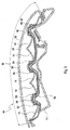
- an IR light source 40 is implemented in the turn-indicator light module 10.
- Fig. 1a shows a front view of the preferred turn-indicator light module 10 comprising two coplanar light guiding elements 20a, 20b and Fig. 1b is a longitudinal cut through the upper light guide 20a. Visible and IR light can exit light emitting surfaces 38a, 38b of the light guiding elements 20a, 20b, i.e. the front side of the light guiding elements 20a, 20b.
- the light emitting surfaces 38a, 38b are comprised by a major portion of the longitudinal extensions 18a, 18b of the light guiding elements 20a, 20b.
- the light guiding elements 20a, 20b are formed in a way to follow smoothly the contour of the turn-light indicator module 10.
- Each of the light guiding elements 20a, 20b is coupled to a visible-light emitting light source 50, such as e.g. a LED.
- the visible-light emitting light source 50 can also be a bulb or the like.
- the IR light and the visible light is coupled in the light guiding elements 20a, 20b at one end of the light guiding elements 20a, 20b.
- the surfaces of the light guiding elements 20a, 20b show structures 22a, 22b (at the front side) and light deflecting structures 24a, 24c at the rear side which allows light which is emitted by the visible-light emitting light source 50 at a first front end 26a, 26b towards a second front end 28a, 28b of the light guiding elements 20a, 20b to exit the light guiding elements 20a, 20b at spatially separate locations at the front side of the light guiding elements 20a, 20b defined by the structures 22a, 22b, 24a, 24c, as generally described in EP 1 657 111 A2 .
- the light guiding elements 20a, 20b are arranged in the interior 16 of a housing 12.
- the light guiding elements 20a, 20b are arranged in front of a reflector 14 which reflects light exiting on the rear side of the light guiding elements 20a, 20b towards the front side of the turn-indicator light module 10 which is closed by a light pane 30.
- the upper light guide 20a is coupled to an IR light emitting source 40 additionally to the visible-light emitting light source 50.
- IR light can exit the light guiding element 20a at its front and rear side together with visible light without interfering with the turn-indicator light module's function in the visible range.
- the IR light emitting light source 40 can emit IR light in a field of vision corresponding to the field of vision covered by the visible light.
- the turn-indicator light module 10 can be integrated into a vehicle mirror assembly, particularly a rear view mirror assembly.
- Fig. 2a and 2b depict another example embodiment of a preferred turn-indicator light module 10 of a preferred rear view mirror assembly as disclosed in DE 10 2005 013 682 A1 , the disclosure of which is hereby included by reference in its entirety.
- DE 10 2005 013 682 A1 describes an outside rear-view mirror having a mirror head and a housing comprising a recess for a flashing turn-light indicator provided with a light pane and light-guiding elements embodied as optical cable into which light may be coupled by at least one lighting means.
- the optical cable extends on the outside of the light pane and protrudes into the housing through the light pane, so the light coupling point is located inside the housing. The corresponding lighting means may therefore not be seen from the outside.
- the outside rear-view mirror is particularly suitable for motor vehicles.
- the optical cable allows the statutory requirements with respect to light values when indicating to be met and a uniform illumination to be achieved.
- an IR light source 40 is implemented in the turn-indicator light module 10.
- Fig. 2a shows a front view of the side of an exterior rear view mirror assembly 60 opposite to a mirror 66 covering an internal space 74 of a mirror housing 64.
- the turn-indicator light module 10, which is a turn indicator, is integrated in the rear view mirror assembly 60.
- Fig. 2b exhibits a longitudinal cut through the mirror housing 64 of the mirror head 62 and the turn-indicator light module 10.
- the IR light and the visible light is coupled in the light guiding elements 20c, 20d, 20e at one end 26 of the light guiding elements 20c, 20d, 20e.
- the light sources 40, 50 are located inside the rear view mirror assemble 60 and is hidden from the view from the outside.
- the light guiding elements 20c, 20d, 20e are formed in a way to follow smoothly the contour of the turn-light indicator module 10 and the contour of the mirror housing 64.
- a light pane 30 exhibits light guiding elements 20c, 20d, 20e which are arranged on an outer surface of the light pane 30.
- the front ends 34 of the light guiding elements 20c, 20d, 20e are located inside the mirror housing 64, pierce through the light pane 30 at points 36 and end at the distal end 28 adjacent to a distal end 32 of the light pane 30.
- IR light and visible light can exit the light guiding elements 20c, 20d, 20e all along their longitudinal extensions 18c, 18e, 18d between first ends 26 and second ends 28 on the front sides of the light guiding elements 20c, 20d, 20e, the front sides forming light emitting surfaces 38c, 38d, 38e of the turn-indicator light module 10.
- visible-light emitting light sources 50 are arranged at the front ends 34 of the light guiding elements 20c, 20d, 20e.
- SMD surface mounted device
- an IR light emitting source 40 is coupled to the light guiding element 20d. It is possible to couple an IR emitting light source 40 to more than one of the light guiding elements 20c, 20d, 20e. As in the example embodiment of Figs.
- IR light can exit the light guiding element 20d at its front side together with visible light without interfering with the turn-indicator light module's function in the visible range. Additionally, if the visible-light emitting light source 50 is not active, the IR light emitting light source 40 can emit IR light.
- Fig. 3 depicts a partial longitudinal cut through a detail of a preferred rear view mirror assembly as disclosed in EP 1 120 312 A2 , the disclosure of which is hereby included by reference in its entirety.
- An exterior rearview mirror for vehicles is disclosed by EP 1 120 312 A2 which has a mirror head housing having a light-transmitting light plate arranged therein. At least one lighting unit is received in the mirror head housing and has at least one light source emitting light rays so as to pass through the fight-transmitting light pane to the exterior of the mirror head housing. At least one reflector is positioned between the at least one light source and the light-transmitting light plate. The at least one reflector has at least one opening, and the at least one light source is positioned in the at least one opening.
- the at least one lighting unit has a lighting unit housing and the at least one light source is arranged in the lighting unit housing which is received in a receptacle of the mirror head housing.
- one or more IR light sources 40 are implemented in the turn-indicator light module 10 additional to a multitude of visible-light emitting light sources 50 such as LEDs which are arranged in reflectors 14. IR light and visible light can exit the light guiding element 20 all along its longitudinal extensions 18 between a first end 26 and a second end 28 on the front sides of the light guiding elements 20, the front side forming light emitting surfaces 38 of the turn-indicator light module 10.
- the light guiding element 20 forms the light pane 30 of the turn-indicator light module 10.
- the IR and the visible light is coupled in the light guiding element 20 along its longitudinal extension 18.
- the light guiding element 20 is formed in a way to follow smoothly the contour of the turn-light indicator module 10.
- Visible-light emitting light sources 50 are located in the vertex of each of several paraboloidically shaped reflectors 14.
- the reflectors 14 are covered by a light pane 30.
- Electrical connections are provided by a foil 54 which connects the LEDs of the turn-indicator light module 10 with a power supply (not shown).
- a protecting cover 56 is arranged between the foil 54 and the reflectors 14 which protects the foil 54 against moisture, dirt and the like.
- the light pane 30 is preferably embodied as a light guiding element 20.
- the IR light source 40 can be arranged at one of the locations of the visible-light emitting light sources 50 or as indicated close to one end of the light pane 30.
- Fig. 4 depicts a partial longitudinal cut through a preferred rear view mirror assembly comprising a preferred turn-indicator light module 10 as a turn indicator as disclosed in EP 0 941 892 A2 the disclosure of which is hereby included by reference in its entirety.
- one or more IR light sources 40 are implemented in the turn-indicator light module 10.
- the rear view mirror disclosed in EP 0 941 892 A2 has an LED as visible light source protruding partially from the opening of the covering section.
- LEDs are arranged on the end surface of the opening, facing away from the car, over the length and/or breadth of the light transmitting light pane.
- the LEDs are arranged behind an optical element formed by a Fresnel lens.
- the Fresnel lens is located in the area between the cover section and the light window.
- the lens is connected with the covering section.
- the LEDs are located in a housing, connected to the cover section.
- the housing is located on the side of the cover section turned away from the light window.
- a U-shaped fluorescent tube can be used as the visible light source
- a separate light guiding element 21 is provided for the one or more IR light emitting light sources 40, which overlays a light emitting surface 38 of a light pane 30 provided for a multitude of visible-light emitting light sources 50 positioned in a housing 68 beneath a Fresnel optical element 58.
- the Fresnel optical element 58 is placed in a cut-out of a mirror housing 64 and allows the emission of visible light through the light pane 30 more or less perpendicular to its longitudinal extension.
- the separate IR light guiding element 21 is extending from a first end 26 to a second end 28 with its longitudinal extension 18.
- IR light can exit the separate light guiding element 21 along its longitudinal extension 18 through its light emitting surface parallel to the light emitting surface 38 of the visible light.
- the IR light source 40 is located at the first end 26 of the light guiding element 20, coupled in the light guiding element 20 and transmitted to the separate light guiding element 21.
- the light guiding element 20 is formed in a way to follow smoothly the contour of the turn-light indicator module 10.
- the light pane 30 can be embodied as a light guiding element 20.
- An additional visible-light emitting light source 50 is placed at one end of the light pane 30 the light of which is transmitted towards the opposite end 28 of the light pane 30
- an IR emitting light source 40 can be placed, the IR light of which can be coupled preferably into the light guiding element 21.
- Fig. 5 depicts a preferred rear view mirror assembly 60 equipped with a preferred turn-indicator light module 10 as disclosed in EP 0 997 346 A1 the disclosure of which is hereby included by reference in its entirety.
- the mirror assembly 60 is attached to a vehicle body with a mirror foot 70.
- one or more IR light sources 40 are implemented in the turn-indicator light module 10 in the mirror head 62 of the mirror assembly 60.
- a light pane 30 which is embodied as light guiding element 20 forms a cover of the turn-indicator light module 10.
- the external rear view mirror according to EP 0 997 346 A1 has a mirror foot and a mirror head, which has a mirror glass carrier, and in which at least one turn-light indicator module is accommodated, which lies behind a light transmitting light pane.
- the turn-light indicator module is arranged in the mirror head in a way that it emits light in the main direction of motion of the vehicle rearwards at an angle of at least 55 degrees with reference to a straight line running outside the contour of the mirror head, lying parallel to the vehicle axis.
- the angle range may be least 60 degrees.
- the turn-light indicator module is located in the front of an ellipsoidal reflector, in a focal point of the reflector. In another focal point, the light beams reflected by the reflector intersect each other.
- a visible-light emitting light source 50 can be placed which illuminates the end 72.
- one or more visible-light emitting light sources 50 can be arranged.
- An IR emitting light source 40 can be placed at the end 72 and/or inside the housing 64. The light emitted by the IR emitting light source 40 can be coupled into the light guiding element 20 and illuminate the ambient of the vehicle.
- the light guiding element 20 has a longitudinal extension 18 which follows smoothly the contour of the turn-indicator light module 10 and the mirror housing 64.
- IR emitting light sources 40 By implementing one or more IR emitting light sources 40 in the turn-indicator light modules 10 of the various embodiments shown in the Figs. 1-5 , it is possible to illuminate fields of view 102, 104, 106 of a vehicle 100 which are illuminated by the visible-light emitting light sources 50 of the turn-indicator light module 10 and the mirror assembly 60 in which the turn-indicator light module 10 is incorporated.
- a driver 110 in a normal seating position, indicated by a pair of eyes, can use the rear vision mirror assembly 60 in its conventional way while the turn-indicator light module 10 allows for illuminating various areas with visible light and/or IR light for various sensors such as e.g. a pre-crash sensor using a field of vision 102, a bird-view sensor using the field of vision 104 and/or a blind-spot-detection sensor making use of the field of vision
Abstract
Description
- The invention pertains to a turn-indicator light module for a vehicle mirror assembly and a vehicle mirror assembly comprising turn-indicator light module according to the preambles of the independent claims.
- Modern vehicles are equipped with multiple sensors in order to support the driver and to increase the active and passive safety of the vehicle. For instance, headlamps can be controlled to generate either low beams or high beams. Low beams provide less illumination and are used to illuminate the forward path when other vehicles are present ahead of the ego vehicle. High beams provide more illumination and are used to illuminate the forward path when no other vehicles are present ahead of the ego vehicle.
- An increasing number of optical functions have to be integrated in a vehicle and in a rear view mirror assembly. The patent
US 7,049,945 B2 discloses a vehicular blind spot detection system which employs infrared (IR) light emitting diodes (LED) for illuminating objects to be detected by the blind spot detection system. - In
EP 1 466 785 A1 a turn indicator assembly is disclosed wherein a light source of the turn indicator and a near-IR LED for night-time illumination are housed in a door mirror assembly. An IR portion of the light emitted by the light source is attenuated in order to avoid dazzling an infrared camera employed for surveying the vehicle's ambient in night-time. - It is an object of the invention to provide an improved and compact turn-indicator light module for a vehicle mirror assembly which can emit infrared light. Another object of the invention is to provide a vehicle mirror assembly comprising an infrared light emitting turn-indicator light module.
- The objects are achieved by the features of the independent claims. The other claims and the description disclose advantageous embodiments of the invention.
- According to a first aspect of the invention a turn-indicator light module is proposed. The turn-indicator light module has an outer contour and comprises one or more light guiding elements and one or more visible-light emitting light sources coupled to at least one of the one or more light guiding elements, wherein at least one infrared light emitting light source is coupled to at least one of the one or more light guiding elements. At least a major portion of a longitudinal extension between a first end and a second end opposite of the first end of the one or more light guiding elements follows the outer contour, and the one or more light guiding elements are adapted to emit light at least along the major portion of their longitudinal extension.
- The IR light can be coupled out along said major portion of the longitudinal extension of said one or more light guiding elements in a homogeneous way, so that for instance the front side of said major portion of the light guiding elements appear homogeneously illuminated, or in an inhomogeneous way, so that for instance separated spots are illuminated creating light and dark areas along said major portion of the light guiding elements. The shape of said light guiding elements can have the form of a rod, a fiber, a band, a disk or the like. The major portion can be e.g. at least 50% of the longitudinal extension of the one or more light guiding elements.
- Advantageously, it is possible to provide a passive IR illumination for various purposes. The visible-light emitting sources can preferably emit light in the visible wavelength spectrum between blue and red. Favorably, it is possible to integrate an infrared (IR) light source into otherwise conventional turn-indicator light modules. It is of a particular advantage that the turn-indicator light module can be integrated in a mirror assembly of a vehicle and/or coupled to other light units particularly in a vehicle. Expediently, the turn-indicator light module can be adapted to transport IR light in an expedient way. Particularly, one or more light guiding elements can be provided to transport IR light as well as visible light, e.g. by selecting the light guide material to be able to transport visible as well as IR light and/or an arrangement can be provided where at least one light guide for transmitting IR light and at least one light guide for transmitting visible light are provided.
- A separate light guiding element can be provided for the one or more infrared light emitting light source of the turn-indicator light module. The one or more light guiding elements can be arranged at appropriate locations for illumination e.g. one or more fields of view of sensors, imaging systems or the like. According to a favorable improvement, the separate light guiding element provided for propagation of infrared light can be arranged in front of a light emitting surface of the one or more light guiding elements provided for one or more visible-light emitting light sources. Alternatively, the separate light guiding element provided for propagation of infrared light can be arranged behind a surface opposite to the light emitting surface of the one or more light guiding elements provided for one or more visible-light emitting light sources. The separate light guiding element provided for propagation of infrared light can be arranged alternately in front of and behind the light emitting surface along the longitudinal extension of the light guiding element provided for propagation of infrared light. Particularly, the separate light guiding element provided for propagation of infrared light can be arranged coplanar to the one or more light guiding elements provided for the propagation of visible light with respect to the light emitting surface of the one or more light guiding element provided for the propagation of visible light.
- A compact arrangement is achieved which has desired visible properties, e.g. the flashing light of the turn indicator, as well as additional functions provided by the IR illumination along the one or more light-guiding elements. The normal function of the turn-indicator light module concerning the illumination by the one or more visible-light emitting light sources is not deteriorated.
- Additionally or alternatively, one or more infrared light emitting light sources and one or more visible-light emitting light sources are coupled to at least one of the same one or more light guiding elements. This arrangement is very compact and space saving. The normal function of the turn-indicator light module concerning the illumination by the one or more visible-light emitting light sources is not deteriorated.
- According to a favorable embodiment, at least one of the one or more light guiding elements to which the one or more infrared light emitting light sources are coupled can be arranged behind a light pane or in front of a light pane, and can particularly be arranged parallel to the light pane. The light pane is light-transmitting and forms usually the outer surface of the turn-indicator light module which covers the turn-indicator light module. As the light pane usually defines the exit surface of light from a light module the orientation of the light pane can indicate into which direction the IR light is emitted from the turn-indicator light module.
- According to a favorable embodiment, at least one of the one or more light guiding elements to which the one or more infrared light emitting light sources are coupled can pierce through the light pane. The location of said at least one of the one or more light guiding elements can easily be arranged according to a desired design and/or function of said at least one of the one or more light guiding elements.
- According to a favorable embodiment, at least one of the one or more light guiding elements to which the one or more infrared light emitting light sources are coupled can be integrated in a light pane. The advantage is a compact arrangement as the said the one or more light guiding elements do not need extra construction space. Further, the orientation of the light pane can indicate into which direction the IR light is emitted from the turn indictor light module.
- Advantageously, infrared light can be coupled in at least in one of the one of more guiding elements and the light pane. The coupling of the IR light can be chosen according to requirements of a desired function to be fulfilled by the IR light emission and/or space requirements in the turn-indicator light module.
- According to a favorable embodiment, infrared light can be coupled in at least at one end of the one of more light guiding elements and/or along the longitudinal extension of the one or more light guiding elements. Various designs of light guiding elements and turn-indicator light modules can be provided.
- According to a favorable embodiment, infrared light can be coupled in at least at one end of the one of more light guiding elements opposite to an end where visible light is coupled in the one or more light guiding elements. Advantageously, IR light can be coupled in into the side of the light guiding element where visible light is coupled out of the light guiding element. Particularly, IR light can be coupled in in a direction opposite to a main direction of motion of a vehicle which comprises the turn light indicator module. A rear vision function with IR light can be achieved.
- According to a favorable embodiment, at least one of the one or more light guiding elements to which the one or more infrared light emitting light sources are coupled can be provided with spatially separated structures for coupling out infrared light at spatially distinct locations along the longitudinal extension of said one or more the light guiding elements. The function of spatially separated IR light sources can be simulated.
- According to another object of the invention, a mirror assembly is proposed comprising a turn-indicator light module according to any feature described above, wherein the turn-indicator light module has an outer contour and comprises one or more light guiding elements and one or more visible-light emitting light sources coupled to at least one of the one or more light guiding elements, and wherein at least one infrared light emitting light source is coupled to at least one of the one or more light guiding elements. At least a major portion of a longitudinal extension between a first end and a second end opposite of the first end of the one or more light guiding elements follows the outer contour, and the one or more light guiding elements are adapted to emit light at least along the major portion of their longitudinal extension.
- The mirror assembly favorably provides passive IR illumination in a compact and reliable turn-indicator light module. In conventional mirror assemblies, such as exterior or interior rear vision mirror assemblies of a vehicle, it is possible to integrate IR illumination for sensors such as bird-view sensor with a field of vision oriented downwards to the surface the vehicle is located or moving, a blind-spot sensor with a field of vision oriented to the rear side of the vehicle, a pre-crash sensor oriented to a field of vision sideward and/or in front of the vehicle, and the like. Preferably, one or more sensors can be integrated in the mirror assembly which can make use of the IR irradiation provided by the turn-indicator light module. However, the sensor and the turn-indicator light module can also be mounted in separate locations at a vehicle, thus allowing for a variability of an adequate design of a sensor/illumination arrangement.
- Favorably, at least one of the light guiding elements coupled to the one or more infrared light emitting light source can provided for illuminating a field of vision with infrared light.
- According to a preferred embodiment, the infrared light emitting source can be coupled to an imaging system and/or a detector system. A night time vision can be considerably improved.
- A separate light guiding element can be provided for the one or more infrared light emitting light source. The separate light guide can be particularly adapted for the transmission of IR light.
- A particular space-saving arrangement is possible if the separate light guiding element provided for propagation of infrared light can be arranged in front of a light emitting surface of the one or more light guiding element provided for one or more visible-light emitting light sources and/or behind a surface opposite to the light emitting surface of the one or more light guiding element provided for one or more visible-light emitting light sources.
- The present invention together with the above-mentioned and other objects and advantages may best be understood from the following detailed description of the embodiments, but not restricted to the embodiments, wherein is shown schematically:
- Fig. 1a, 1b
- a front view (
Fig. 1a ) of a first embodiment of a preferred turn-indicator light module and a longitudinal cut through the preferred turn-indicator light module (Fig. 1b ) according to the invention; - Fig. 2a, 2b
- a front view of a preferred mirror assembly (
Fig. 2a ) according to the invention comprising a second preferred embodiment of a turn-indicator light module and a longitudinal cut through the preferred mirror assembly (Fig. 2b ); - Fig. 3
- a longitudinal cut through a third preferred embodiment of a turn-indicator light module according to the invention;
- Fig. 4
- a longitudinal cut through a fourth preferred embodiment of a turn-indicator light module according to the invention;
- Fig. 5
- a top view of a preferred mirror assembly according to the invention; and
- Fig. 6
- a representation of different fields of view illuminated by an infrared light source in a preferred external rear view mirror assembly according to the invention.
- In the drawings, equal or similar elements are referred to by equal reference numerals. The drawings are merely schematic representations, not intended to portray specific parameters of the invention. Moreover, the drawings are intended to depict only typical embodiments of the invention and therefore should not be considered as limiting the scope of the invention.
-
Fig. 1a and1b depict an example embodiment of a preferred turn-indicator light module 10 of a preferred rear view mirror assembly as disclosed inEP 1 657 111 A2 , the disclosure of which is hereby included by reference in its entirety. - The turn-indicator light module disclosed in
EP 1 657 111 has two parallel light guiding elements embodied as optical fibers including a set of deflecting structures, which deflect light that falls on the structures in such a manner that the light comes out of a front side of the optical fiber along the longitudinal extension. A set of optically operative structures is arranged over a length of the optical fiber and a part of the resigning light is emitted in angular areas extending transverse to a driving direction (main direction of motion) of the vehicle comprising the turn-indicator light module. - According to the invention an IR light source 40 is implemented in the turn-
indicator light module 10.Fig. 1a shows a front view of the preferred turn-indicator light module 10 comprising two coplanarlight guiding elements Fig. 1b is a longitudinal cut through the upperlight guide 20a. Visible and IR light can exit light emittingsurfaces light guiding elements light guiding elements light emitting surfaces longitudinal extensions light guiding elements light guiding elements light indicator module 10. - Each of the
light guiding elements light source 50, such as e.g. a LED. The visible-light emittinglight source 50 can also be a bulb or the like. The IR light and the visible light is coupled in thelight guiding elements light guiding elements - The surfaces of the
light guiding elements 20b show structures light deflecting structures light source 50 at a firstfront end front end light guiding elements light guiding elements light guiding elements structures EP 1 657 111 A2 . - The
light guiding elements interior 16 of ahousing 12. Thelight guiding elements reflector 14 which reflects light exiting on the rear side of thelight guiding elements indicator light module 10 which is closed by alight pane 30. - The upper
light guide 20a is coupled to an IR light emitting source 40 additionally to the visible-light emittinglight source 50. IR light can exit thelight guiding element 20a at its front and rear side together with visible light without interfering with the turn-indicator light module's function in the visible range. Additionally, if the visible-light emittinglight source 50 is not active, the IR light emitting light source 40 can emit IR light in a field of vision corresponding to the field of vision covered by the visible light. The turn-indicator light module 10 can be integrated into a vehicle mirror assembly, particularly a rear view mirror assembly. -
Fig. 2a and 2b depict another example embodiment of a preferred turn-indicator light module 10 of a preferred rear view mirror assembly as disclosed inDE 10 2005 013 682 A1 -
DE 10 2005 013 682 A1 - According to the invention, an IR light source 40 is implemented in the turn-
indicator light module 10.Fig. 2a shows a front view of the side of an exterior rearview mirror assembly 60 opposite to amirror 66 covering aninternal space 74 of amirror housing 64. The turn-indicator light module 10, which is a turn indicator, is integrated in the rearview mirror assembly 60.Fig. 2b exhibits a longitudinal cut through themirror housing 64 of themirror head 62 and the turn-indicator light module 10. - The IR light and the visible light is coupled in the
light guiding elements end 26 of thelight guiding elements light sources 40, 50 are located inside the rear view mirror assemble 60 and is hidden from the view from the outside. Thelight guiding elements light indicator module 10 and the contour of themirror housing 64. - As already described in
DE 10 2005 013 682 A1light pane 30 exhibits light guidingelements light pane 30. The front ends 34 of thelight guiding elements mirror housing 64, pierce through thelight pane 30 atpoints 36 and end at thedistal end 28 adjacent to adistal end 32 of thelight pane 30. IR light and visible light can exit thelight guiding elements longitudinal extensions light guiding elements surfaces indicator light module 10. - At the front ends 34 of the
light guiding elements light sources 50 are arranged. By way of example, the visible-light emittinglight sources 50 are SMD-LEDs (SMD = surface mounted device) which are mounted onboards 52. Additionally to the visible-light emittinglight source 50 of thelight guiding element 20d an IR light emitting source 40 is coupled to thelight guiding element 20d. It is possible to couple an IR emitting light source 40 to more than one of thelight guiding elements Figs. 1 a and 1b, IR light can exit thelight guiding element 20d at its front side together with visible light without interfering with the turn-indicator light module's function in the visible range. Additionally, if the visible-light emittinglight source 50 is not active, the IR light emitting light source 40 can emit IR light. -
Fig. 3 depicts a partial longitudinal cut through a detail of a preferred rear view mirror assembly as disclosed inEP 1 120 312 A2 , the disclosure of which is hereby included by reference in its entirety. - An exterior rearview mirror for vehicles is disclosed by
EP 1 120 312 A2 which has a mirror head housing having a light-transmitting light plate arranged therein. At least one lighting unit is received in the mirror head housing and has at least one light source emitting light rays so as to pass through the fight-transmitting light pane to the exterior of the mirror head housing. At least one reflector is positioned between the at least one light source and the light-transmitting light plate. The at least one reflector has at least one opening, and the at least one light source is positioned in the at least one opening. The at least one lighting unit has a lighting unit housing and the at least one light source is arranged in the lighting unit housing which is received in a receptacle of the mirror head housing. - In the turn-
indicator light module 10 according to the invention, which is comprised by such exterior rearview mirror, one or more IR light sources 40 are implemented in the turn-indicator light module 10 additional to a multitude of visible-light emittinglight sources 50 such as LEDs which are arranged inreflectors 14. IR light and visible light can exit thelight guiding element 20 all along itslongitudinal extensions 18 between afirst end 26 and asecond end 28 on the front sides of thelight guiding elements 20, the front side forminglight emitting surfaces 38 of the turn-indicator light module 10. Thelight guiding element 20 forms thelight pane 30 of the turn-indicator light module 10. - The IR and the visible light is coupled in the
light guiding element 20 along itslongitudinal extension 18. Thelight guiding element 20 is formed in a way to follow smoothly the contour of the turn-light indicator module 10. - Visible-light emitting
light sources 50 are located in the vertex of each of several paraboloidically shapedreflectors 14. Thereflectors 14 are covered by alight pane 30. Electrical connections are provided by afoil 54 which connects the LEDs of the turn-indicator light module 10 with a power supply (not shown). Between thefoil 54 and the reflectors 14 a protectingcover 56 is arranged which protects thefoil 54 against moisture, dirt and the like. Thelight pane 30 is preferably embodied as alight guiding element 20. The IR light source 40 can be arranged at one of the locations of the visible-light emittinglight sources 50 or as indicated close to one end of thelight pane 30. -
Fig. 4 depicts a partial longitudinal cut through a preferred rear view mirror assembly comprising a preferred turn-indicator light module 10 as a turn indicator as disclosed inEP 0 941 892 A2 the disclosure of which is hereby included by reference in its entirety. According to the invention one or more IR light sources 40 are implemented in the turn-indicator light module 10. - The rear view mirror disclosed in
EP 0 941 892 A2 has an LED as visible light source protruding partially from the opening of the covering section. Several LEDs are arranged on the end surface of the opening, facing away from the car, over the length and/or breadth of the light transmitting light pane. The LEDs are arranged behind an optical element formed by a Fresnel lens. The Fresnel lens is located in the area between the cover section and the light window. The lens is connected with the covering section. The LEDs are located in a housing, connected to the cover section. The housing is located on the side of the cover section turned away from the light window. Alternatively a U-shaped fluorescent tube can be used as the visible light source - According to this example embodiment of the invention, a separate
light guiding element 21 is provided for the one or more IR light emitting light sources 40, which overlays alight emitting surface 38 of alight pane 30 provided for a multitude of visible-light emittinglight sources 50 positioned in ahousing 68 beneath a Fresneloptical element 58. The Fresneloptical element 58 is placed in a cut-out of amirror housing 64 and allows the emission of visible light through thelight pane 30 more or less perpendicular to its longitudinal extension. The separate IRlight guiding element 21 is extending from afirst end 26 to asecond end 28 with itslongitudinal extension 18. IR light can exit the separatelight guiding element 21 along itslongitudinal extension 18 through its light emitting surface parallel to thelight emitting surface 38 of the visible light. The IR light source 40 is located at thefirst end 26 of thelight guiding element 20, coupled in thelight guiding element 20 and transmitted to the separatelight guiding element 21. Thelight guiding element 20 is formed in a way to follow smoothly the contour of the turn-light indicator module 10. - The
light pane 30 can be embodied as alight guiding element 20. An additional visible-light emittinglight source 50 is placed at one end of thelight pane 30 the light of which is transmitted towards theopposite end 28 of thelight pane 30 - Additional to this visible-light emitting
light source 50 an IR emitting light source 40 can be placed, the IR light of which can be coupled preferably into thelight guiding element 21. -
Fig. 5 depicts a preferred rearview mirror assembly 60 equipped with a preferred turn-indicator light module 10 as disclosed inEP 0 997 346 A1 the disclosure of which is hereby included by reference in its entirety. Themirror assembly 60 is attached to a vehicle body with amirror foot 70. According to the invention, one or more IR light sources 40 are implemented in the turn-indicator light module 10 in themirror head 62 of themirror assembly 60. Alight pane 30 which is embodied as light guidingelement 20 forms a cover of the turn-indicator light module 10. - The external rear view mirror according to
EP 0 997 346 A1 has a mirror foot and a mirror head, which has a mirror glass carrier, and in which at least one turn-light indicator module is accommodated, which lies behind a light transmitting light pane. The turn-light indicator module is arranged in the mirror head in a way that it emits light in the main direction of motion of the vehicle rearwards at an angle of at least 55 degrees with reference to a straight line running outside the contour of the mirror head, lying parallel to the vehicle axis. The angle range may be least 60 degrees. The turn-light indicator module is located in the front of an ellipsoidal reflector, in a focal point of the reflector. In another focal point, the light beams reflected by the reflector intersect each other. - According to this example embodiment of the invention, at one
end 72 of the mirror's housing 64 a visible-light emittinglight source 50 can be placed which illuminates theend 72. In an inner space of themirror assembly 60 one or more visible-light emittinglight sources 50 can be arranged. An IR emitting light source 40 can be placed at theend 72 and/or inside thehousing 64. The light emitted by the IR emitting light source 40 can be coupled into thelight guiding element 20 and illuminate the ambient of the vehicle. Thelight guiding element 20 has alongitudinal extension 18 which follows smoothly the contour of the turn-indicator light module 10 and themirror housing 64. - By implementing one or more IR emitting light sources 40 in the turn-
indicator light modules 10 of the various embodiments shown in theFigs. 1-5 , it is possible to illuminate fields ofview vehicle 100 which are illuminated by the visible-light emittinglight sources 50 of the turn-indicator light module 10 and themirror assembly 60 in which the turn-indicator light module 10 is incorporated. This is shown inFig. 6 by way of example of a rearview mirror assembly 60. Adriver 110 in a normal seating position, indicated by a pair of eyes, can use the rearvision mirror assembly 60 in its conventional way while the turn-indicator light module 10 allows for illuminating various areas with visible light and/or IR light for various sensors such as e.g. a pre-crash sensor using a field ofvision 102, a bird-view sensor using the field ofvision 104 and/or a blind-spot-detection sensor making use of the field ofvision 106.
Claims (15)
- A turn-indicator light module (10) having an outer contour and comprising one or more light guiding elements (20, 20a-20e) and one or more visible-light emitting light sources (50) coupled to at least one of the one or more light guiding elements (20, 20a-20e, 21), wherein at least one infrared light emitting light source (40) is coupled to at least one of the one or more light guiding elements (20, 20a-20e, 21), wherein at least a major portion of a longitudinal extension (18, 18a-18e) between a first end (26, 26a, 26b) and a second end opposite of the first end (28, 28a, 28b) of the one or more light guiding elements (20, 20a-20e, 21) follows the outer contour and wherein the one or more light guiding elements (20, 20a-20e, 21) are adapted to emit light at least along the major portion of their longitudinal extension (18, 18a-18e).
- The turn-indicator light module according to claim 1, wherein a separate light guiding element (21) is provided for the one or more infrared light emitting light source (40).
- The turn-indicator light module according to claim 2, wherein the separate light guiding element (21) provided for propagation of infrared light is arranged in front of a light emitting surface (38) of the one or more light guiding element (20) provided for one or more visible-light emitting light sources (50) and/or behind a surface opposite to the light emitting surface (38) of the one or more light guiding element (20) provided for one or more visible-light emitting light sources (50).
- The turn-indicator light module according to claims 2 or 3, wherein the separate light guiding element (21) provided for propagation of infrared light is arranged coplanar to the one or more light guiding elements (20, 20a-20e) with respect to the light emitting surface (38) of the one or more light guiding element (20, 20a, 20e).
- The turn-indicator light module according to any preceding claim, wherein one or more infrared light emitting light sources (40) and one or more visible-light emitting light sources (50) are coupled to at least the same of one or more light guiding elements (20, 20a-20e).
- The turn-indicator light module according to any preceding claim, wherein at least one of the one or more light guiding elements (20, 20a-20e) to which the one or more infrared light emitting light sources (40) are coupled is arranged behind a light pane (30) or in front of a light pane (30), and particularly arranged parallel to the light pane (30).
- The turn-indicator light module according to any preceding claim, wherein at least one of the one or more light guiding elements (20, 20a-20e) pierces through the light pane (30).
- The turn-indicator light module according to any preceding claim, wherein at least one of the one or more light guiding elements (20, 20a-20e) to which the one or more infrared light emitting light sources (40) are coupled is integrated in a light pane (30).
- The turn-indicator light module according to anyone of the claims 6 to 8, wherein infrared light is coupled in at least in one of the one of more guiding elements (20, 20a-20e) and the light pane (30).
- The turn-indicator light module according to any preceding claim, wherein infrared light is coupled in at least at one end (26, 26a, 26b, 28. 28a. 28b) of the one of more light guiding elements (20, 20a-20e) and/or along the longitudinal extension (18, 18a-18e) of the one or more light guiding elements (20, 20a-20e).
- The turn-indicator light module according to any preceding claim, wherein infrared light is coupled in at least at one end (26, 26a, 26b, 28, 28a, 28b) of the one of more light guiding elements (20, 20a-20e) opposite to an end (26, 26a, 26b, 28, 28a, 28b) where visible light is coupled in the one or more light guiding elements (20, 20a-20e).
- The turn-indicator light module according to any preceding claim, wherein at least one of the one or more light guiding elements (20, 20a-20e) to which the one or more infrared light emitting light sources (40) are coupled is provided with spatially separated structures (22a, 22b) for coupling out infrared light at spatially distinct locations.
- A mirror assembly (60) comprising a turn-indicator light module (10) according to any preceding claim.
- The mirror assembly according to claim 13, wherein at least one or more light guiding elements (20, 20a-20e, 21) are coupled to one or more infrared light emitting light sources (40) provided for illuminating a field of vision with infrared light.
- The mirror assembly according to anyone of the claims 13 or 14, wherein the infrared light emitting source (40) is coupled to an imaging system and/or a detector system.
Priority Applications (2)
| Application Number | Priority Date | Filing Date | Title |
|---|---|---|---|
| EP09006001A EP2119595B1 (en) | 2008-05-16 | 2009-04-30 | Turn-indicator light module for a vehicle mirror assembly and vehicle mirror assembly comprising a turn-indicator light module |
| US12/466,106 US8477044B2 (en) | 2008-05-16 | 2009-05-14 | Turn-indicator light module for a vehicle mirror assembly and vehicle mirror assembly comprising a turn-indicator light module |
Applications Claiming Priority (2)
| Application Number | Priority Date | Filing Date | Title |
|---|---|---|---|
| EP08009048A EP2123514A1 (en) | 2008-05-16 | 2008-05-16 | Light module for a vehicle mirror assembly and vehicle mirror assembly comprising a light module |
| EP09006001A EP2119595B1 (en) | 2008-05-16 | 2009-04-30 | Turn-indicator light module for a vehicle mirror assembly and vehicle mirror assembly comprising a turn-indicator light module |
Publications (2)
| Publication Number | Publication Date |
|---|---|
| EP2119595A1 true EP2119595A1 (en) | 2009-11-18 |
| EP2119595B1 EP2119595B1 (en) | 2012-11-28 |
Family
ID=39811963
Family Applications (2)
| Application Number | Title | Priority Date | Filing Date |
|---|---|---|---|
| EP08009048A Withdrawn EP2123514A1 (en) | 2008-05-16 | 2008-05-16 | Light module for a vehicle mirror assembly and vehicle mirror assembly comprising a light module |
| EP09006001A Active EP2119595B1 (en) | 2008-05-16 | 2009-04-30 | Turn-indicator light module for a vehicle mirror assembly and vehicle mirror assembly comprising a turn-indicator light module |
Family Applications Before (1)
| Application Number | Title | Priority Date | Filing Date |
|---|---|---|---|
| EP08009048A Withdrawn EP2123514A1 (en) | 2008-05-16 | 2008-05-16 | Light module for a vehicle mirror assembly and vehicle mirror assembly comprising a light module |
Country Status (2)
| Country | Link |
|---|---|
| US (1) | US8477044B2 (en) |
| EP (2) | EP2123514A1 (en) |
Cited By (7)
| Publication number | Priority date | Publication date | Assignee | Title |
|---|---|---|---|---|
| DE102011016404A1 (en) * | 2011-04-08 | 2012-10-11 | GM Global Technology Operations LLC (n. d. Gesetzen des Staates Delaware) | Optical device for motor vehicle, is arranged at lateral wall element and has optically active, particularly reflective upper surface that faces motor vehicle, where illuminating device is provided with illuminating unit |
| EP2762361A1 (en) * | 2010-12-10 | 2014-08-06 | SMR Patents S.à.r.l. | Lighting unit |
| EP2853444A1 (en) * | 2013-09-26 | 2015-04-01 | Fico Mirrors S.A. | Mirror device for motor vehicles and method for assembling thereof |
| CN108302495A (en) * | 2016-09-23 | 2018-07-20 | 株式会社小糸制作所 | Lamps apparatus for vehicle and the outer rear-view mirror device of car body |
| US10539294B2 (en) | 2015-01-19 | 2020-01-21 | SMR Patents S.à.r.l. | Automobile exterior rear view mirror blind spot warning indication device |
| EP3981648A1 (en) * | 2017-08-25 | 2022-04-13 | SMR Patents S.à.r.l. | Rearview device and vehicle with such rear view device |
| US11305696B2 (en) | 2017-08-25 | 2022-04-19 | SMR Patents S.à.r.l. | Rearview device and vehicle with such rearview device |
Families Citing this family (16)
| Publication number | Priority date | Publication date | Assignee | Title |
|---|---|---|---|---|
| CZ306862B6 (en) * | 2011-06-23 | 2017-08-16 | Varroc Lighting Systems, s.r.o. | A headlight signal lamp with a hidden light source |
| US11220217B2 (en) * | 2013-01-24 | 2022-01-11 | SMR Patents S.à.r.l. | Rearview device with moveable head assembly and method of assembling same |
| JP5937836B2 (en) * | 2012-02-07 | 2016-06-22 | 株式会社小糸製作所 | Vehicle lighting |
| JP2015173057A (en) * | 2014-03-12 | 2015-10-01 | ヤマハ株式会社 | Acoustic equipment and bracket for linear lighting device of the same |
| KR101592676B1 (en) * | 2014-03-20 | 2016-02-12 | 현대자동차주식회사 | Planar Lighting Mirror with Nano-patterns |
| JP2016137753A (en) * | 2015-01-26 | 2016-08-04 | 株式会社東海理化電機製作所 | Direction indication device for vehicle |
| DE102015104163A1 (en) * | 2015-03-19 | 2016-09-22 | SMR Patents S.à.r.l. | Lighting device and method for producing a lighting device |
| US9697393B2 (en) | 2015-11-20 | 2017-07-04 | Symbol Technologies, Llc | Methods and systems for adjusting mobile-device operating parameters based on housing-support type |
| DE102016101997A1 (en) * | 2016-02-04 | 2017-08-10 | SMR Patents S.à.r.l. | Lighting device and rearview device for vehicles |
| JP6569882B2 (en) * | 2016-03-17 | 2019-09-11 | 本田技研工業株式会社 | Vehicle lighting |
| US10184635B2 (en) | 2016-10-24 | 2019-01-22 | Varroc Lighting Systems, s.r.o. | Light device |
| CN106828324B (en) * | 2017-01-25 | 2023-10-20 | 宁波胜维德赫华翔汽车镜有限公司 | Blind zone warning indicator for automobile outer rear-view mirror |
| CN110500553A (en) * | 2018-05-16 | 2019-11-26 | 深圳市绎立锐光科技开发有限公司 | Light supply apparatus and car headlamp |
| US11396986B2 (en) | 2019-05-23 | 2022-07-26 | Valeo North America, Inc. | Apparatus and method for masking residual visible light from an infrared emission source |
| DE102020108943B4 (en) * | 2020-03-31 | 2022-04-28 | HELLA GmbH & Co. KGaA | Lighting device for vehicles |
| DE102020128316B3 (en) | 2020-10-28 | 2022-03-24 | Zkw Group Gmbh | MOTOR VEHICLE HEADLIGHT FOR DETECTING A MOTOR VEHICLE ENVIRONMENT |
Citations (12)
| Publication number | Priority date | Publication date | Assignee | Title |
|---|---|---|---|---|
| EP0941892A2 (en) | 1998-03-13 | 1999-09-15 | Reitter & Schefenacker GmbH & Co. KG | Exterior rear view mirror, in particular for a motor vehicle |
| EP0997346A1 (en) | 1998-10-29 | 2000-05-03 | Reitter & Schefenacker GmbH & Co. KG | Exterior rear view mirror for vehicles , especially motor vehicles |
| US6160948A (en) * | 1997-05-21 | 2000-12-12 | Mcgaffigan; Thomas H. | Optical light pipes with laser light appearance |
| EP1120312A2 (en) | 2000-01-27 | 2001-08-01 | Reitter & Schefenacker GmbH & Co. KG | Exterior rear view mirror for vehicles, in particular for automotive vehicles |
| EP1391755A2 (en) * | 2002-08-21 | 2004-02-25 | Hella KG Hueck & Co. | Vehicle lamp |
| EP1466785A1 (en) | 2003-04-09 | 2004-10-13 | Toyota Jidosha Kabushiki Kaisha | Side turn signal lamp, periphery monitoring device, body construction and imaging device for vehicle |
| WO2005075247A1 (en) * | 2004-02-06 | 2005-08-18 | Daimlerchrysler Ag | Vehicle with an infrared illuminator |
| US20050243568A1 (en) | 2000-07-12 | 2005-11-03 | Alejandro Rodriguez Barros | Set of parts and assembling method for assembling a rear-view side mirror of a vehicle |
| EP1657111A2 (en) | 2004-11-15 | 2006-05-17 | FER Fahrzeugelektrik GmbH | Side blinker lamp |
| DE102005013682A1 (en) | 2005-03-18 | 2006-09-21 | Schefenacker Vision Systems Germany Gmbh | Exterior rearview mirror of vehicles, preferably motor vehicles |
| DE102005019018A1 (en) * | 2005-04-23 | 2006-10-26 | Volkswagen Ag | Motor vehicle lamp, has optical waveguide with mutually spaced light entry surfaces |
| DE102006007884A1 (en) * | 2006-02-21 | 2007-08-30 | Daimlerchrysler Ag | Light arrangement e.g. for motor vehicle outside mirror, provided at motor vehicle outside mirror housing, at which light surface of indicator signal is provided |
Family Cites Families (6)
| Publication number | Priority date | Publication date | Assignee | Title |
|---|---|---|---|---|
| GB2369737B (en) | 2000-05-08 | 2005-02-02 | Automotive Tech Int | Vehicular blind spot identification and monitoring system |
| DE10218437A1 (en) * | 2002-04-25 | 2004-01-15 | Hella Kg Hueck & Co. | Light unit for vehicle, has separation arrangement and second light conductor for passing defined separated spectral component of emitted light via second light conductor to further outlet point |
| US20040218041A1 (en) * | 2003-01-30 | 2004-11-04 | Ichikoh Industries, Ltd. | Outside mirror for vehicle |
| DE102004048669B4 (en) * | 2003-10-07 | 2007-06-14 | Toyoda Gosei Co., Ltd. | Vehicle side mirror device |
| JP4791262B2 (en) * | 2006-06-14 | 2011-10-12 | 本田技研工業株式会社 | Driving assistance device |
| JP4276250B2 (en) * | 2006-10-11 | 2009-06-10 | 株式会社ミツバ | Door mirror with turn lamp |
-
2008
- 2008-05-16 EP EP08009048A patent/EP2123514A1/en not_active Withdrawn
-
2009
- 2009-04-30 EP EP09006001A patent/EP2119595B1/en active Active
- 2009-05-14 US US12/466,106 patent/US8477044B2/en active Active
Patent Citations (12)
| Publication number | Priority date | Publication date | Assignee | Title |
|---|---|---|---|---|
| US6160948A (en) * | 1997-05-21 | 2000-12-12 | Mcgaffigan; Thomas H. | Optical light pipes with laser light appearance |
| EP0941892A2 (en) | 1998-03-13 | 1999-09-15 | Reitter & Schefenacker GmbH & Co. KG | Exterior rear view mirror, in particular for a motor vehicle |
| EP0997346A1 (en) | 1998-10-29 | 2000-05-03 | Reitter & Schefenacker GmbH & Co. KG | Exterior rear view mirror for vehicles , especially motor vehicles |
| EP1120312A2 (en) | 2000-01-27 | 2001-08-01 | Reitter & Schefenacker GmbH & Co. KG | Exterior rear view mirror for vehicles, in particular for automotive vehicles |
| US20050243568A1 (en) | 2000-07-12 | 2005-11-03 | Alejandro Rodriguez Barros | Set of parts and assembling method for assembling a rear-view side mirror of a vehicle |
| EP1391755A2 (en) * | 2002-08-21 | 2004-02-25 | Hella KG Hueck & Co. | Vehicle lamp |
| EP1466785A1 (en) | 2003-04-09 | 2004-10-13 | Toyota Jidosha Kabushiki Kaisha | Side turn signal lamp, periphery monitoring device, body construction and imaging device for vehicle |
| WO2005075247A1 (en) * | 2004-02-06 | 2005-08-18 | Daimlerchrysler Ag | Vehicle with an infrared illuminator |
| EP1657111A2 (en) | 2004-11-15 | 2006-05-17 | FER Fahrzeugelektrik GmbH | Side blinker lamp |
| DE102005013682A1 (en) | 2005-03-18 | 2006-09-21 | Schefenacker Vision Systems Germany Gmbh | Exterior rearview mirror of vehicles, preferably motor vehicles |
| DE102005019018A1 (en) * | 2005-04-23 | 2006-10-26 | Volkswagen Ag | Motor vehicle lamp, has optical waveguide with mutually spaced light entry surfaces |
| DE102006007884A1 (en) * | 2006-02-21 | 2007-08-30 | Daimlerchrysler Ag | Light arrangement e.g. for motor vehicle outside mirror, provided at motor vehicle outside mirror housing, at which light surface of indicator signal is provided |
Cited By (9)
| Publication number | Priority date | Publication date | Assignee | Title |
|---|---|---|---|---|
| EP2762361A1 (en) * | 2010-12-10 | 2014-08-06 | SMR Patents S.à.r.l. | Lighting unit |
| DE102011016404A1 (en) * | 2011-04-08 | 2012-10-11 | GM Global Technology Operations LLC (n. d. Gesetzen des Staates Delaware) | Optical device for motor vehicle, is arranged at lateral wall element and has optically active, particularly reflective upper surface that faces motor vehicle, where illuminating device is provided with illuminating unit |
| EP2853444A1 (en) * | 2013-09-26 | 2015-04-01 | Fico Mirrors S.A. | Mirror device for motor vehicles and method for assembling thereof |
| US10274155B2 (en) | 2013-09-26 | 2019-04-30 | Fico Mirrors, S.A. | Mirror device for motor vehicles and method for assembling thereof |
| US10539294B2 (en) | 2015-01-19 | 2020-01-21 | SMR Patents S.à.r.l. | Automobile exterior rear view mirror blind spot warning indication device |
| CN108302495A (en) * | 2016-09-23 | 2018-07-20 | 株式会社小糸制作所 | Lamps apparatus for vehicle and the outer rear-view mirror device of car body |
| EP3981648A1 (en) * | 2017-08-25 | 2022-04-13 | SMR Patents S.à.r.l. | Rearview device and vehicle with such rear view device |
| US11305696B2 (en) | 2017-08-25 | 2022-04-19 | SMR Patents S.à.r.l. | Rearview device and vehicle with such rearview device |
| US11738689B2 (en) | 2017-08-25 | 2023-08-29 | SMR Patents S.à.r.l. | Rearview device and vehicle with such rearview device |
Also Published As
| Publication number | Publication date |
|---|---|
| EP2123514A1 (en) | 2009-11-25 |
| US8477044B2 (en) | 2013-07-02 |
| US20090284365A1 (en) | 2009-11-19 |
| EP2119595B1 (en) | 2012-11-28 |
Similar Documents
| Publication | Publication Date | Title |
|---|---|---|
| EP2119595B1 (en) | Turn-indicator light module for a vehicle mirror assembly and vehicle mirror assembly comprising a turn-indicator light module | |
| US11597322B2 (en) | Vehicular exterior mirror system with light module | |
| US8469563B2 (en) | Turn-indicator light module for a vehicle mirror assembly and vehicle mirror assembly comprising a turn-indicator light module | |
| US7204625B2 (en) | Phototherapy device | |
| EP1442934B1 (en) | Outside mirror for vehicle | |
| US9360183B2 (en) | Mirror apparatus for a vehicle | |
| KR20060101279A (en) | Exterior rear view mirror of vehicles, preferably motor vehicles | |
| US8177401B2 (en) | Light guide turn signal indicator rear view mirror | |
| EP1442930B1 (en) | Exterior mirror with light | |
| KR20090064326A (en) | Vehicular lamp | |
| KR20070007306A (en) | Exterior rearview mirror for vehicles, especially for motor vehicles | |
| CN105083108A (en) | Lighting unit | |
| US6095672A (en) | Lighting device for the rear end of a vehicle | |
| KR20190068808A (en) | Structure for Ambient light of the Roof of the Vehicle | |
| KR101428097B1 (en) | Lamp for vehicle | |
| US20050036329A1 (en) | Motor-vehicle headlight | |
| EP1498311B1 (en) | Infrared projector | |
| JP4214882B2 (en) | Night vision lamp for vehicle and vehicle outside mirror device | |
| US7217018B1 (en) | Structure of automobile lamp | |
| US8425095B2 (en) | Mirror assembly | |
| JP2002236178A (en) | Object detection device on moving body | |
| US11754251B2 (en) | Vehicular lamp | |
| WO2023157757A1 (en) | Lighting tool for vehicle and vehicle rearward illumination system | |
| JP7090220B2 (en) | Bicycle headlights | |
| KR200284078Y1 (en) | Automotive rearview mirror with multifunction lamp |
Legal Events
| Date | Code | Title | Description |
|---|---|---|---|
| PUAI | Public reference made under article 153(3) epc to a published international application that has entered the european phase |
Free format text: ORIGINAL CODE: 0009012 |
|
| AK | Designated contracting states |
Kind code of ref document: A1 Designated state(s): AT BE BG CH CY CZ DE DK EE ES FI FR GB GR HR HU IE IS IT LI LT LU LV MC MK MT NL NO PL PT RO SE SI SK TR |
|
| 17P | Request for examination filed |
Effective date: 20091023 |
|
| 17Q | First examination report despatched |
Effective date: 20100204 |
|
| GRAP | Despatch of communication of intention to grant a patent |
Free format text: ORIGINAL CODE: EPIDOSNIGR1 |
|
| GRAS | Grant fee paid |
Free format text: ORIGINAL CODE: EPIDOSNIGR3 |
|
| GRAA | (expected) grant |
Free format text: ORIGINAL CODE: 0009210 |
|
| AK | Designated contracting states |
Kind code of ref document: B1 Designated state(s): AT BE BG CH CY CZ DE DK EE ES FI FR GB GR HR HU IE IS IT LI LT LU LV MC MK MT NL NO PL PT RO SE SI SK TR |
|
| REG | Reference to a national code |
Ref country code: GB Ref legal event code: FG4D |
|
| REG | Reference to a national code |
Ref country code: CH Ref legal event code: EP |
|
| REG | Reference to a national code |
Ref country code: AT Ref legal event code: REF Ref document number: 585971 Country of ref document: AT Kind code of ref document: T Effective date: 20121215 |
|
| REG | Reference to a national code |
Ref country code: IE Ref legal event code: FG4D |
|
| REG | Reference to a national code |
Ref country code: DE Ref legal event code: R096 Ref document number: 602009011471 Country of ref document: DE Effective date: 20130124 |
|
| REG | Reference to a national code |
Ref country code: AT Ref legal event code: MK05 Ref document number: 585971 Country of ref document: AT Kind code of ref document: T Effective date: 20121128 |
|
| REG | Reference to a national code |
Ref country code: NL Ref legal event code: VDEP Effective date: 20121128 |
|
| REG | Reference to a national code |
Ref country code: LT Ref legal event code: MG4D |
|
| PG25 | Lapsed in a contracting state [announced via postgrant information from national office to epo] |
Ref country code: FI Free format text: LAPSE BECAUSE OF FAILURE TO SUBMIT A TRANSLATION OF THE DESCRIPTION OR TO PAY THE FEE WITHIN THE PRESCRIBED TIME-LIMIT Effective date: 20121128 Ref country code: SE Free format text: LAPSE BECAUSE OF FAILURE TO SUBMIT A TRANSLATION OF THE DESCRIPTION OR TO PAY THE FEE WITHIN THE PRESCRIBED TIME-LIMIT Effective date: 20121128 Ref country code: ES Free format text: LAPSE BECAUSE OF FAILURE TO SUBMIT A TRANSLATION OF THE DESCRIPTION OR TO PAY THE FEE WITHIN THE PRESCRIBED TIME-LIMIT Effective date: 20130311 Ref country code: LT Free format text: LAPSE BECAUSE OF FAILURE TO SUBMIT A TRANSLATION OF THE DESCRIPTION OR TO PAY THE FEE WITHIN THE PRESCRIBED TIME-LIMIT Effective date: 20121128 Ref country code: NO Free format text: LAPSE BECAUSE OF FAILURE TO SUBMIT A TRANSLATION OF THE DESCRIPTION OR TO PAY THE FEE WITHIN THE PRESCRIBED TIME-LIMIT Effective date: 20130228 |
|
| PG25 | Lapsed in a contracting state [announced via postgrant information from national office to epo] |
Ref country code: LV Free format text: LAPSE BECAUSE OF FAILURE TO SUBMIT A TRANSLATION OF THE DESCRIPTION OR TO PAY THE FEE WITHIN THE PRESCRIBED TIME-LIMIT Effective date: 20121128 Ref country code: PT Free format text: LAPSE BECAUSE OF FAILURE TO SUBMIT A TRANSLATION OF THE DESCRIPTION OR TO PAY THE FEE WITHIN THE PRESCRIBED TIME-LIMIT Effective date: 20130328 Ref country code: BE Free format text: LAPSE BECAUSE OF FAILURE TO SUBMIT A TRANSLATION OF THE DESCRIPTION OR TO PAY THE FEE WITHIN THE PRESCRIBED TIME-LIMIT Effective date: 20121128 Ref country code: PL Free format text: LAPSE BECAUSE OF FAILURE TO SUBMIT A TRANSLATION OF THE DESCRIPTION OR TO PAY THE FEE WITHIN THE PRESCRIBED TIME-LIMIT Effective date: 20121128 Ref country code: GR Free format text: LAPSE BECAUSE OF FAILURE TO SUBMIT A TRANSLATION OF THE DESCRIPTION OR TO PAY THE FEE WITHIN THE PRESCRIBED TIME-LIMIT Effective date: 20130301 Ref country code: SI Free format text: LAPSE BECAUSE OF FAILURE TO SUBMIT A TRANSLATION OF THE DESCRIPTION OR TO PAY THE FEE WITHIN THE PRESCRIBED TIME-LIMIT Effective date: 20121128 Ref country code: CY Free format text: LAPSE BECAUSE OF FAILURE TO SUBMIT A TRANSLATION OF THE DESCRIPTION OR TO PAY THE FEE WITHIN THE PRESCRIBED TIME-LIMIT Effective date: 20121128 |
|
| PG25 | Lapsed in a contracting state [announced via postgrant information from national office to epo] |
Ref country code: AT Free format text: LAPSE BECAUSE OF FAILURE TO SUBMIT A TRANSLATION OF THE DESCRIPTION OR TO PAY THE FEE WITHIN THE PRESCRIBED TIME-LIMIT Effective date: 20121128 |
|
| PG25 | Lapsed in a contracting state [announced via postgrant information from national office to epo] |
Ref country code: EE Free format text: LAPSE BECAUSE OF FAILURE TO SUBMIT A TRANSLATION OF THE DESCRIPTION OR TO PAY THE FEE WITHIN THE PRESCRIBED TIME-LIMIT Effective date: 20121128 Ref country code: SK Free format text: LAPSE BECAUSE OF FAILURE TO SUBMIT A TRANSLATION OF THE DESCRIPTION OR TO PAY THE FEE WITHIN THE PRESCRIBED TIME-LIMIT Effective date: 20121128 Ref country code: CZ Free format text: LAPSE BECAUSE OF FAILURE TO SUBMIT A TRANSLATION OF THE DESCRIPTION OR TO PAY THE FEE WITHIN THE PRESCRIBED TIME-LIMIT Effective date: 20121128 Ref country code: BG Free format text: LAPSE BECAUSE OF FAILURE TO SUBMIT A TRANSLATION OF THE DESCRIPTION OR TO PAY THE FEE WITHIN THE PRESCRIBED TIME-LIMIT Effective date: 20130228 Ref country code: DK Free format text: LAPSE BECAUSE OF FAILURE TO SUBMIT A TRANSLATION OF THE DESCRIPTION OR TO PAY THE FEE WITHIN THE PRESCRIBED TIME-LIMIT Effective date: 20121128 |
|
| PG25 | Lapsed in a contracting state [announced via postgrant information from national office to epo] |
Ref country code: RO Free format text: LAPSE BECAUSE OF FAILURE TO SUBMIT A TRANSLATION OF THE DESCRIPTION OR TO PAY THE FEE WITHIN THE PRESCRIBED TIME-LIMIT Effective date: 20121128 Ref country code: IT Free format text: LAPSE BECAUSE OF FAILURE TO SUBMIT A TRANSLATION OF THE DESCRIPTION OR TO PAY THE FEE WITHIN THE PRESCRIBED TIME-LIMIT Effective date: 20121128 Ref country code: NL Free format text: LAPSE BECAUSE OF FAILURE TO SUBMIT A TRANSLATION OF THE DESCRIPTION OR TO PAY THE FEE WITHIN THE PRESCRIBED TIME-LIMIT Effective date: 20121128 |
|
| PLBE | No opposition filed within time limit |
Free format text: ORIGINAL CODE: 0009261 |
|
| STAA | Information on the status of an ep patent application or granted ep patent |
Free format text: STATUS: NO OPPOSITION FILED WITHIN TIME LIMIT |
|
| 26N | No opposition filed |
Effective date: 20130829 |
|
| PG25 | Lapsed in a contracting state [announced via postgrant information from national office to epo] |
Ref country code: MC Free format text: LAPSE BECAUSE OF FAILURE TO SUBMIT A TRANSLATION OF THE DESCRIPTION OR TO PAY THE FEE WITHIN THE PRESCRIBED TIME-LIMIT Effective date: 20121128 |
|
| REG | Reference to a national code |
Ref country code: CH Ref legal event code: PL |
|
| REG | Reference to a national code |
Ref country code: DE Ref legal event code: R097 Ref document number: 602009011471 Country of ref document: DE Effective date: 20130829 |
|
| REG | Reference to a national code |
Ref country code: IE Ref legal event code: MM4A |
|
| PG25 | Lapsed in a contracting state [announced via postgrant information from national office to epo] |
Ref country code: HR Free format text: LAPSE BECAUSE OF FAILURE TO SUBMIT A TRANSLATION OF THE DESCRIPTION OR TO PAY THE FEE WITHIN THE PRESCRIBED TIME-LIMIT Effective date: 20130731 Ref country code: LI Free format text: LAPSE BECAUSE OF NON-PAYMENT OF DUE FEES Effective date: 20130430 Ref country code: CH Free format text: LAPSE BECAUSE OF NON-PAYMENT OF DUE FEES Effective date: 20130430 |
|
| PG25 | Lapsed in a contracting state [announced via postgrant information from national office to epo] |
Ref country code: IE Free format text: LAPSE BECAUSE OF NON-PAYMENT OF DUE FEES Effective date: 20130430 |
|
| PG25 | Lapsed in a contracting state [announced via postgrant information from national office to epo] |
Ref country code: MT Free format text: LAPSE BECAUSE OF FAILURE TO SUBMIT A TRANSLATION OF THE DESCRIPTION OR TO PAY THE FEE WITHIN THE PRESCRIBED TIME-LIMIT Effective date: 20121128 |
|
| PG25 | Lapsed in a contracting state [announced via postgrant information from national office to epo] |
Ref country code: TR Free format text: LAPSE BECAUSE OF FAILURE TO SUBMIT A TRANSLATION OF THE DESCRIPTION OR TO PAY THE FEE WITHIN THE PRESCRIBED TIME-LIMIT Effective date: 20121128 |
|
| PG25 | Lapsed in a contracting state [announced via postgrant information from national office to epo] |
Ref country code: LU Free format text: LAPSE BECAUSE OF NON-PAYMENT OF DUE FEES Effective date: 20130430 Ref country code: HU Free format text: LAPSE BECAUSE OF FAILURE TO SUBMIT A TRANSLATION OF THE DESCRIPTION OR TO PAY THE FEE WITHIN THE PRESCRIBED TIME-LIMIT; INVALID AB INITIO Effective date: 20090430 Ref country code: MK Free format text: LAPSE BECAUSE OF FAILURE TO SUBMIT A TRANSLATION OF THE DESCRIPTION OR TO PAY THE FEE WITHIN THE PRESCRIBED TIME-LIMIT Effective date: 20121128 |
|
| REG | Reference to a national code |
Ref country code: FR Ref legal event code: PLFP Year of fee payment: 8 |
|
| PG25 | Lapsed in a contracting state [announced via postgrant information from national office to epo] |
Ref country code: IS Free format text: LAPSE BECAUSE OF FAILURE TO SUBMIT A TRANSLATION OF THE DESCRIPTION OR TO PAY THE FEE WITHIN THE PRESCRIBED TIME-LIMIT Effective date: 20121128 |
|
| REG | Reference to a national code |
Ref country code: FR Ref legal event code: PLFP Year of fee payment: 9 |
|
| REG | Reference to a national code |
Ref country code: FR Ref legal event code: PLFP Year of fee payment: 10 |
|
| REG | Reference to a national code |
Ref country code: DE Ref legal event code: R084 Ref document number: 602009011471 Country of ref document: DE |
|
| P01 | Opt-out of the competence of the unified patent court (upc) registered |
Effective date: 20230616 |
|
| PGFP | Annual fee paid to national office [announced via postgrant information from national office to epo] |
Ref country code: FR Payment date: 20230424 Year of fee payment: 15 Ref country code: DE Payment date: 20230420 Year of fee payment: 15 |
|
| PGFP | Annual fee paid to national office [announced via postgrant information from national office to epo] |
Ref country code: GB Payment date: 20230419 Year of fee payment: 15 |