EP2131382A2 - Single socket lamp - Google Patents
Single socket lamp Download PDFInfo
- Publication number
- EP2131382A2 EP2131382A2 EP09159886A EP09159886A EP2131382A2 EP 2131382 A2 EP2131382 A2 EP 2131382A2 EP 09159886 A EP09159886 A EP 09159886A EP 09159886 A EP09159886 A EP 09159886A EP 2131382 A2 EP2131382 A2 EP 2131382A2
- Authority
- EP
- European Patent Office
- Prior art keywords
- base
- damping element
- lamp according
- lamp
- ring
- Prior art date
- Legal status (The legal status is an assumption and is not a legal conclusion. Google has not performed a legal analysis and makes no representation as to the accuracy of the status listed.)
- Granted
Links
Images


Classifications
-
- H—ELECTRICITY
- H01—ELECTRIC ELEMENTS
- H01J—ELECTRIC DISCHARGE TUBES OR DISCHARGE LAMPS
- H01J61/00—Gas-discharge or vapour-discharge lamps
- H01J61/02—Details
- H01J61/30—Vessels; Containers
- H01J61/34—Double-wall vessels or containers
-
- H—ELECTRICITY
- H01—ELECTRIC ELEMENTS
- H01J—ELECTRIC DISCHARGE TUBES OR DISCHARGE LAMPS
- H01J5/00—Details relating to vessels or to leading-in conductors common to two or more basic types of discharge tubes or lamps
- H01J5/50—Means forming part of the tube or lamps for the purpose of providing electrical connection to it
- H01J5/54—Means forming part of the tube or lamps for the purpose of providing electrical connection to it supported by a separate part, e.g. base
- H01J5/58—Means for fastening the separate part to the vessel, e.g. by cement
- H01J5/60—Means for fastening the separate part to the vessel, e.g. by cement for fastening by mechanical means
Definitions
- the invention relates to a single-capped lamp according to the preamble of claim 1.
- These are in particular high-pressure discharge lamps, preferably metal halide lamps, but also, for example, halogen incandescent lamps.
- an elongate, in particular ceramic, discharge vessel is used as lamp bulb.
- a single-ended lamp which is composed of three pistons. It has a ceramic adapter, which is mounted on a screw base. There is atmospheric pressure between the outer bulb and the outer bulb.
- the EP 1 109 199 describes a single-capped high-pressure lamp in which the outer bulb is surrounded by a reflector.
- the base is attached by crimping directly to the reflector neck.
- the disadvantage of this is that the dimension of the neck of the reflector must be matched to the standard dimensions of the base.
- modularly produced lamps in particular high-pressure discharge lamps, advantageously require those having a ceramic discharge vessel, a damping element. It is used between outer bulb and base ceramic, so that in the specific manufacturing processes no glass breakage can occur.
- a damping element according to WO2005015605 a commercial O-ring used.
- the single-ended lamp has a vacuum-sealed lamp bulb, in particular an elongated discharge vessel, which may still be accommodated in an outer bulb, wherein the lamp bulb, ie the discharge vessel or the discharge tube assembly with outer bulb, is still surrounded by a Hüllteil.
- a ceramic discharge vessel in particular for a metal halide lamp, for example for general lighting purposes.
- the electrical connections are normally connected to power supply lines, which produce an electrical contact to a light source inside the lamp bulb, for example, the light source is realized by electrodes or a luminous element of an incandescent lamp.
- external electrodes may also be used, or an electrodeless configuration.
- a discharge vessel made of quartz glass or hard glass can also be used.
- An outer bulb is not essential.
- the sheath part is fastened by a bracket part bridging the distance between the lower plateau of the base stone and at least the upper contact surface of the edge.
- the enveloping part and the clamp part form a unit, wherein the holder of the enveloping part is realized in the upper part of the base brick, for example by crimping.
- the base has, in addition to the base stone on a conventional, the socket facing part, for example, a screw base approach or bayonet socket approach.
- the lamp bulb so for example, the outer bulb or the discharge vessel in the absence of an outer bulb, held in the central opening by means of a spring clip.
- This technique is known in principle, see for example DE 198 56 871 ,
- edge of the Hüllteils and the segment of the base stone is equipped with a cooperating Verfitschutzmechanismus.
- the clamp part consists of circumferentially distributed brackets or a circumferential clamp tape.
- the staple band is a deformable ring, which is made in particular of metal or plastic, so that a very simple holder is made possible by the fact that the staple band is already angled at the lower edge, and it is raised to the stop over the base stone to the projecting segment.
- the ring preferably made of aluminum, can be mechanically formed on the segment, and thus fix the edge of the Hüllteils.
- the prior art is that between the clamp part and the upper contact surface of the edge of the Hüllteils a damping means is introduced. It is in particular a kind of O-ring, for example made of an elastomer.
- the material of the Hüllteils preferably glass or aluminum, protected during the Anformreaes from damage.
- the damping element is made in one piece from temperature-resistant, preferably elastic, plastic.
- the damping element is made in one piece from temperature-resistant, preferably elastic, plastic.
- two main functions are realized simultaneously.
- damping is achieved when connecting outer bulb and base ceramic, as is known.
- the damping element is designed as a ring, in which extends at least one web shoulder at two opposite points within the ring.
- the web extension is designed as a continuous web extending between the two web extensions. However, it can also be interrupted in the middle, so that there are two separate web approaches.
- the web or the web approaches can guide holes, in particular for the power supply of the base lamp or similar.
- the ring may preferably be a or a plurality of recesses, such as a locking groove, to ensure a desired orientation of the damping element with proper alignment of the web approaches.
- the lamp then has a corresponding counterpart, for example in the field of base ceramic.
- the ring may also consist of two parts, preferably symmetrical halves, which do not have to be connected to each other and which also do not have to give a complete ring.
- the manufacturing process is carried out as follows:
- the damping element (1) is placed on the plateau of the base ceramic (2).
- two fracture-sensitive materials namely the glass outer bulb (3) and the base ceramic (2) are mechanically connected by means of an aluminum ring (4).
- the base ceramic is preferably made of steatite. Between the two materials is located to prevent breakage, preferably one-piece damping element (1).
- the previously used O-ring also achieves damping and prevents breakage. However, due to its shape, this is not necessarily stable in terms of location. That he could, either during assembly or when screwing the finished lamp in the socket slip. Piston misalignment or a loose piston would be the result. This can no longer occur in the case of a one-piece, flat damping element (1).
- the web approach is pulled so far inward that it simultaneously ensures damping when joining a base lamp in a base ceramic.
- the damping element (1) is placed on the plateau of the base ceramic (2).
- a base lamp (7) provided with a clip (6) is inserted into the shaft (8) of the base ceramic (2) by means of a suitable device.
- the device works with a firm stop.
- the total length of the base lamp varies due to the existing tolerance, the z. Gr. Part is determined by the down freely expiring Quetschungsunterkante (9).
- the fixed stop of the joining device is set once with the aid of existing base lamps.
- the bottom edge of the base lamp squeezing must be joined as close as possible to the plateau (2) of the base ceramic, but must not come in contact with the base ceramic, as this carries a high risk of cracks and flaking.
- the pinch bottom edge (9) would be pressed onto the plateau of the base ceramic.
- the device has a spring element for this case. However, the force required for the joining process can still damage the pinch.
- damping element (1) prevents this largely.
- Suitable materials for the damping element in particular Teflon or silicone rubber VMQ or Viton FPM in question.
- the thickness of the damping element should preferably be between 0.5 and 1.5 mm, including boundary values.
- One advantage is that the connecting force between the enveloping part and the segment remains free of play due to the damping element over the life of the lamp. Due to the damping ring, the tension of the clamp part can be safe be increased and thus the connection made more reliable.
- the base also has a barrel-facing part, which is at least partially connected as known per se by crimping with the base brick.
- this part contains a standard screw thread.
- the enveloping part may, for example, be a closed part such as another, but not vacuum-sealed, outer bulb, or else a calotte, which has a reflector contour.
- a typical application is a metal halide lamp with a ceramic discharge vessel, which contains a filling with or without mercury content, optionally with inert starting gas, preferably noble gas.
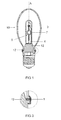
- FIG. 1 and 2 An embodiment of a metal halide lamp 10 shows Fig. 1 and 2 in an exploded view and assembled.
- a ceramic discharge vessel 9, which is closed on two sides, is arranged longitudinally in the lamp axis A and surrounded by a wide enveloping bulb 3.
- the discharge vessel 9 is closely surrounded by an outer bulb 7, which is crimped on one side and made of tempered glass.
- a frame 4 with short and long supply line holds the discharge vessel 9 in the outer bulb 7.
- the electrodes in the interior of the discharge vessel are connected via feedthroughs with the supply lines. The latter are in the region of a pinch seal 6, which closes the outer bulb 3, connected to external power supply lines 11.
- the pinch 6 of the outer bulb is seated in a matching opening 8 of a base 12 made of ceramic and is optionally held there by a metal clip, as known per se (not shown).
- This opening 8 is surrounded by a central collar part 13. It protrudes from a plane which forms the upper plateau 14 of a radially projecting disc-shaped segment 15. It sits on a neck part, which holds a framed assigned part, here a screw base part 19 threaded.
- the neck part is hollow inside, wherein the power supply lines 11 are connected to electrical terminals 21 of the base 23 of the neck portion.
- the enveloping piston 3 is equipped at its opening 25 with a radially projecting edge 27. It has a flat lower contact surface, which is adapted to the upper plateau of the segment of the base stone.
- the upper plateau may have bumps which cause a spacing of the upper plateau to the enveloping piston.
- it has a narrow upper contact surface, which is parallel to the lower contact surface or obliquely aligned.
- An elastomer ring for example made of Viton®, may be placed on it, see below WO 2005015605 ,
- FIG. 5 a further embodiment of a damping element 1 is shown. In him no continuous web is provided, but an extended stub stump 40 each on the web shoulder, each stump still has the holes 32.
- Fig. 6 shows an embodiment of a damping element 1, in which only a very short stub stump 41 is used without holes.
- FIG. 7 shows a further embodiment of a damping element 1, in which a continuous web 31st is used, wherein a guide groove 45 is attached to the outside of the ring outside, in the amount of one of the web approaches, because here enough meat for the recess of the guide groove is present.
- the guide groove can engage in a nose 46 of the base, see FIG. 2 ,
- the annulus has no constant width B, but two more recesses.
- FIG. 8 finally shows a damping element 50 which is composed of two parts 51. Each part is a short semi-ring, each having a web extension 30 and a stub stump 31.
- the damping element is generally a disc cut out of a disc having a given width B that is appreciably greater than the thickness D (see FIG FIG. 2 ) of the disc, so that a position stabilization is achieved.
- a typical value of the width B is 2.5 mm with a typical thickness of 1 mm.
- a typical value range for B is 2 to 4 mm, a typical value range for D is 0.5 to 1.5 mm.
- the ratio B: D is at least 2: 1. It can be up to 8: 1 and possibly even higher. Of course, this condition is still met if in parts the width B is made smaller on the damping element, since it depends only on the stabilization.
- the damping element is of course also with reflector lamps or similar. applicable, see W02005015605 , In this case, the envelope part is the reflector.
Abstract
Description
Die Erfindung betrifft eine einseitig gesockelte Lampe gemäß dem Oberbegriff des Anspruchs 1. Es handelt sich dabei insbesondere um Hochdruckentladungslampen, bevorzugt Metallhalogenidlampen, aber auch beispielsweise um Halogenglühlampen. Häufig wird dabei ein längsgestrecktes, insbesondere keramisches, Entladungsgefäß als Lampenkolben benutzt.The invention relates to a single-capped lamp according to the preamble of
Aus der
Die
Aus der
Es ist Aufgabe der vorliegenden Erfindung, eine einseitig gesockelte Lampe gemäß dem Oberbegriff des Anspruchs 1 bereitzustellen, die einfach zu montieren und gut automatisierbar herzustellen ist.It is an object of the present invention to provide a single-capped lamp according to the preamble of
Diese Aufgabe wird durch die kennzeichnenden Merkmale des Anspruchs 1 gelöst. Besonders vorteilhafte Ausgestaltungen finden sich in den abhängigen Ansprüchen.This object is solved by the characterizing features of
Es hat sich herausgestellt, dass modular gefertigte Lampen, insbesondere Hochdruckentladungslampen, vorteilhaft solche, die ein keramisches Entladungsgefäß aufweisen, ein Dämpfungselement benötigen. Es wird zwischen Außenkolben und Sockelkeramik eingesetzt, damit bei den spezifischen Herstellprozessen kein Glasbruch auftreten kann. Insbesondere kann beim Fügen zwischen einer Einbaulampe oder Basislampe, die oft einen Clip zur Halterung besitzt, in den Schacht einer Sockelkeramik zu einer Beschädigung des unteren Quetschungsbereichs der Quetschung der Basislampe kommen, wenn dieses auf das Plateau der Sockelkeramik aufsetzt. Bisher wurde als Dämpfungselement gemäß
Die einseitig gesockelte Lampe besitzt einen vakuumdicht abgeschlossenen Lampenkolben, insbesondere ein längsgestrecktes Entladungsgefäß, das u.U. noch in einem Außenkolben untergebracht ist, wobei der Lampenkolben, also das Entladungsgefäß oder auch die Baueinheit Entladungsgefäß mit Außenkolben, noch von einem Hüllteil umgeben ist. Bevorzugt handelt es sich um ein keramisches Entladungsgefäß, insbesondere für eine Metallhalogenidlampe, beispielsweise für Allgemeinbeleuchtungszwecke. Dabei trägt ein Sockel mit elektrischen Anschlüssen einerseits den Lampenkolben und andererseits das Hüllteil. Die elektrischen Anschlüsse sind normalerweise mit Stromzuführungen verbunden, die einen elektrischen Kontakt zu einem Leuchtmittel im Innern des Lampenkolben herstellen, beispielsweise ist das Leuchtmittel durch Elektroden oder einem Leuchtkörper einer Glühlampe realisiert. Ohne Beschränkung der Erfindung können auch Außenelektroden verwendet werden, oder eine elektrodenlose Konfiguration. Statt eines keramischen Entladungsgefäßes kann auch ein Entladungsgefäß aus Quarzglas oder Hartglas verwendet werden. Ein Außenkolben ist nicht unbedingt erforderlich.The single-ended lamp has a vacuum-sealed lamp bulb, in particular an elongated discharge vessel, which may still be accommodated in an outer bulb, wherein the lamp bulb, ie the discharge vessel or the discharge tube assembly with outer bulb, is still surrounded by a Hüllteil. It is preferably a ceramic discharge vessel, in particular for a metal halide lamp, for example for general lighting purposes. there carries a socket with electrical connections on the one hand the lamp bulb and on the other hand, the Hüllteil. The electrical connections are normally connected to power supply lines, which produce an electrical contact to a light source inside the lamp bulb, for example, the light source is realized by electrodes or a luminous element of an incandescent lamp. Without limiting the invention, external electrodes may also be used, or an electrodeless configuration. Instead of a ceramic discharge vessel, a discharge vessel made of quartz glass or hard glass can also be used. An outer bulb is not essential.
Häufig wird die Kombination folgender Merkmale eingesetzt, so dass eine umständliche Gestellmontage und heiße Prozesse wie Einschmelzen, Ausheizen des Sockelkitts entfallen:
- a) der Sockel weist einen aus isolierendem Material gefertigten Sockelstein auf, der eine zentrale Öffnung besitzt, in der der Lampenkolben kittlos aufgenommen ist;
- b) der Sockelstein besitzt ein radial vorspringendes Segment, das insbesondere kreisförmig ist, mit einem bezogen auf den Sockel zugehörigen oberen und unteren Plateau;
- c) das Hüllteil besitzt sockelseitig eine, insbesondere kreisförmige, Öffnung mit einem radial vorspringenden Rand oder Randabschnitt, der bezogen auf den Sockel eine untere und obere Kontaktfläche aufweist, wobei die untere Kontaktfläche des Rands oder Randabschnitts mit dem oberen Plateau des radial vorspringenden Segments am Sockelstein zusammenpasst;
- d) das Hüllteil ist am Sockel durch einen kittfreien mechanischen Haltemechanismus befestigt.
- a) the base has a socket made of insulating material, which has a central opening in which the lamp bulb is received without cement;
- b) the base stone has a radially projecting segment, which is in particular circular, with a relation to the base associated upper and lower plateau;
- c) the Hüllteil has a base side, in particular circular, opening with a radially projecting edge or edge portion, based on the base has a lower and upper contact surface, wherein the lower contact surface of the edge or edge portion with the upper plateau of the radially projecting segment on the base stone matches;
- d) the Hüllteil is attached to the base by a putty-free mechanical holding mechanism.
Insbesondere ist das Hüllteil in einer ersten Ausführungsform dadurch befestigt, dass ein Klammerteil die Distanz zwischen dem unteren Plateau des Sockelsteins und mindestens der oberen Kontaktfläche des Randes halternd überbrückt.In particular, in a first embodiment the sheath part is fastened by a bracket part bridging the distance between the lower plateau of the base stone and at least the upper contact surface of the edge.
Ohne Einschränkung der Erfindung kann in einer zweiten Ausführungsform das Hüllteil und das Klammerteil eine Einheit bilden, wobei die Halterung des Hüllteils im oberen Teil des Sockelsteins realisiert wird, beispielsweise durch eine Crimpung.Without limiting the invention, in a second embodiment, the enveloping part and the clamp part form a unit, wherein the holder of the enveloping part is realized in the upper part of the base brick, for example by crimping.
Der Sockel weist neben dem Sockelstein ein übliches, der Fassung zugewandtes Teil auf, beispielsweise einen Schraubsockelansatz oder Bajonettsockelansatz.The base has, in addition to the base stone on a conventional, the socket facing part, for example, a screw base approach or bayonet socket approach.
Bevorzugt ist der Lampenkolben, also beispielsweise der Außenkolben bzw. das Entladungsgefäß im Falle des Fehlens eines Außenkolbens, in der zentralen Öffnung mittels eines Federclips gehaltert. Diese Technik ist im Prinzip an sich bekannt, siehe beispielsweise
Insbesondere ist der Rand des Hüllteils und das Segment des Sockelsteins mit einem zusammen wirkenden Verdrehschutzmechanismus ausgestattet ist.In particular, the edge of the Hüllteils and the segment of the base stone is equipped with a cooperating Verdrehschutzmechanismus.
Eine einfache, zuverlässige und kostengünstige Lösung für die Halterung des Hüllteils besteht darin, dass das Klammerteil aus über den Umfang verteilten Klammern oder einem umlaufenden Klammerband besteht. Insbesondere ist das Klammerband ein verformbarer Ring, der insbesondere aus Metall oder Kunststoff gefertigt ist, so dass eine sehr einfache Halterung dadurch möglich wird, dass das Klammerband zunächst am unteren Rand bereits abgewinkelt ist, und es auf Anschlag über den Sockelstein bis zum vorspringenden Segment hochgezogen wird. Sobald das Hüllteil aufgesetzt ist, kann der Ring, bevorzugt aus Aluminium, mechanisch am Segment angeformt werden, und so den Rand des Hüllteils fixieren.A simple, reliable and cost-effective solution for holding the Hüllteils is that the clamp part consists of circumferentially distributed brackets or a circumferential clamp tape. In particular, the staple band is a deformable ring, which is made in particular of metal or plastic, so that a very simple holder is made possible by the fact that the staple band is already angled at the lower edge, and it is raised to the stop over the base stone to the projecting segment. Once the Hüllteil is placed, the ring, preferably made of aluminum, can be mechanically formed on the segment, and thus fix the edge of the Hüllteils.
Stand der Technik ist es, daß zwischen Klammerteil und oberer Kontaktfläche des Rands des Hüllteils ein Dämpfungsmittel eingebracht ist. Es handelt sich insbesondere um eine Art O-Ring, beispielsweise aus einem Elastomer. Damit wird das Material des Hüllteils, vorteilhaft Glas oder Aluminium, während des Anformprozesses vor Beschädigung geschützt.The prior art is that between the clamp part and the upper contact surface of the edge of the Hüllteils a damping means is introduced. It is in particular a kind of O-ring, for example made of an elastomer. Thus, the material of the Hüllteils, preferably glass or aluminum, protected during the Anformprozesses from damage.
Erfindungsgemäß wird jetzt ein neuartiges Dämpfungselement verwendet. Das Dämpfungselement ist einteilig aus temperaturfestem, vorzugsweise elastischem, Kunststoff gefertigt. Durch die möglichst einteilig, bevorzugt flach ausgeführte Form des Dämpfungselementes, werden zwei Hauptfunktionen gleichzeitig realisiert. Zum einen wird eine Dämpfung beim Verbinden von Außenkolben und Sockelkeramik realisiert, wie bekannt. Gleichzeitig wird eine Dämpfung beim Fügen einer Basislampe in eine Sockelkeramik sichergestellt. Zu diesem Zweck ist das Dämpfungselement als Ring ausgeführt, bei dem sich innerhalb des Rings mindestens ein Stegansatz an zwei einander gegenüberliegenden Punkten erstreckt. Bevorzugt ist der Stegansatz als durchgängiger Steg ausgeführt, der sich zwischen den beiden Stegansätzen erstreckt. Er kann jedoch auch in der Mitte unterbrochen sein, so dass zwei getrennte Stegansätze vorliegen. Der Steg oder die Stegansätze können Führungslöcher, insbesondere für die Stromzuführungen der Basislampe o.ä , aufweisen. Der Ring kann bevorzugt eine oder mehrere Aussparungen, wie eine Rastnut, aufweisen um eine gewünschte Orientierung des Dämpfungselements mit richtiger Ausrichtung der Stegansätze sicherzustellen. Zu diesem Zweck hat die Lampe dann ein entsprechendes Gegenstück, beispielsweise im Bereich der Sockelkeramik. Der Ring kann auch aus zwei Teilen, bevorzugt symmetrischen Hälften bestehen, die nicht miteinander verbunden sein müssen und die auch keinen vollständigen Ring ergeben müssen.According to the invention, a novel damping element is now used. The damping element is made in one piece from temperature-resistant, preferably elastic, plastic. By the possible one-piece, preferably flat running form of the damping element, two main functions are realized simultaneously. On the one hand, damping is achieved when connecting outer bulb and base ceramic, as is known. At the same time damping is ensured when joining a base lamp in a base ceramic. For this purpose, the damping element is designed as a ring, in which extends at least one web shoulder at two opposite points within the ring. Preferably, the web extension is designed as a continuous web extending between the two web extensions. However, it can also be interrupted in the middle, so that there are two separate web approaches. The web or the web approaches can guide holes, in particular for the power supply of the base lamp or similar. The ring may preferably be a or a plurality of recesses, such as a locking groove, to ensure a desired orientation of the damping element with proper alignment of the web approaches. For this purpose, the lamp then has a corresponding counterpart, for example in the field of base ceramic. The ring may also consist of two parts, preferably symmetrical halves, which do not have to be connected to each other and which also do not have to give a complete ring.
Der Herstellprozess wird dabei folgendermaßen ausgeführt:The manufacturing process is carried out as follows:
Das Dämpfungselement (1) wird auf das Plateau der Sockelkeramik (2) gelegt. Mit Hilfe eines speziellen Montageprozesses werden zwei bruchempfindliche Materialien, nämlich der Glasaußenkolben (3) und die Sockelkeramik (2) mittels eines Aluminiumringes (4) mechanisch verbunden. Die Sockelkeramik ist bevorzugt aus Steatit hergestellt. Zwischen den beiden Materialien befindet sich zur Bruchvermeidung das bevorzugt einteilige Dämpfungselement (1). Durch den früher eingesetzten O-Ring wird zwar ebenfalls eine Dämpfung erreicht und Bruch vermieden. Jedoch ist dieser, aufgrund seiner Form, nicht unbedingt lagestabil. D.h. er könnte, entweder bereits bei der Montage oder beim Einschrauben der fertigen Lampe in die Fassung, verrutschen. Kolbenschiefstand oder ein loser Kolben wären die Folge. Dies kann bei einem einteiligen, flach ausgeführten Dämpfungselement (1) nicht mehr auftreten.The damping element (1) is placed on the plateau of the base ceramic (2). With the aid of a special assembly process, two fracture-sensitive materials, namely the glass outer bulb (3) and the base ceramic (2) are mechanically connected by means of an aluminum ring (4). The base ceramic is preferably made of steatite. Between the two materials is located to prevent breakage, preferably one-piece damping element (1). Although the previously used O-ring also achieves damping and prevents breakage. However, due to its shape, this is not necessarily stable in terms of location. That he could, either during assembly or when screwing the finished lamp in the socket slip. Piston misalignment or a loose piston would be the result. This can no longer occur in the case of a one-piece, flat damping element (1).
Bevorzugt ist der Stegansatz so weit nach innen gezogen, dass er gleichzeitig auch eine Dämpfung beim Fügen einer Basislampe in eine Sockelkeramik sicherstellt. In diesem Fall gilt folgendes:Preferably, the web approach is pulled so far inward that it simultaneously ensures damping when joining a base lamp in a base ceramic. In this case the following applies:
Das Dämpfungselement (1) wird auf das Plateau der Sockelkeramik (2) gelegt. Eine mit einem Clip (6) versehene Basislampe (7) wird mit Hilfe einer geeigneten Vorrichtung in den Schacht (8) der Sockelkeramik (2) gefügt. Die Vorrichtung arbeitet mit einem festen Anschlag. Die Gesamtlänge der Basislampe schwankt durch die vorhandene Toleranz, die z. gr. Teil durch die nach unten frei auslaufende Quetschungsunterkante (9) bestimmt wird. Der feste Anschlag der Fügevorrichtung wird einmal mit Hilfe vorhandener Basislampen eingestellt. Die Unterkante der Basislampenquetschung muss so dicht wie möglich an das Plateau (2) der Sockelkeramik gefügt werden, darf aber nicht in Kontakt mit der Sockelkeramik kommen, da dies ein hohes Risiko von Sprüngen und Abplatzungen birgt. Bei längeren Basislampen würde die Quetschungsunterkante (9) auf das Plateau der Sockelkeramik gedrückt werden. Die Vorrichtung besitzt für diesen Fall zwar ein Federelement. Die für den Fügeprozess erforderliche Kraft kann aber dennoch die Quetschung beschädigen.The damping element (1) is placed on the plateau of the base ceramic (2). A base lamp (7) provided with a clip (6) is inserted into the shaft (8) of the base ceramic (2) by means of a suitable device. The device works with a firm stop. The total length of the base lamp varies due to the existing tolerance, the z. Gr. Part is determined by the down freely expiring Quetschungsunterkante (9). The fixed stop of the joining device is set once with the aid of existing base lamps. The bottom edge of the base lamp squeezing must be joined as close as possible to the plateau (2) of the base ceramic, but must not come in contact with the base ceramic, as this carries a high risk of cracks and flaking. For longer base lamps, the pinch bottom edge (9) would be pressed onto the plateau of the base ceramic. Although the device has a spring element for this case. However, the force required for the joining process can still damage the pinch.
Ein, auf das Plateau der Sockelkeramik (2) aufgelegtes, Dämpfungselement (1) verhindert dies weitestgehend.A, on the plateau of the base ceramic (2) placed, damping element (1) prevents this largely.
Als Materialien für das Dämpfungselement kommen insbesondere Teflon oder Silikonkautschuk VMQ oder Viton FPM in Frage. Die Dicke des Dämpfungselementes sollte bevorzugt zwischen 0,5 und 1,5 mm liegen, Randwerte eingeschlossen.Suitable materials for the damping element in particular Teflon or silicone rubber VMQ or Viton FPM in question. The thickness of the damping element should preferably be between 0.5 and 1.5 mm, including boundary values.
Ein Vorteil ist, dass durch das Dämpfungselement über die Lebensdauer der Lampe die Verbindungskraft zwischen Hüllteil und Segment spielfrei erhalten bleibt. Aufgrund des Dämpfungsrings kann die Spannung des Klammerteils gefahrlos erhöht werden und somit die Verbindung zuverlässiger gestaltet werden.One advantage is that the connecting force between the enveloping part and the segment remains free of play due to the damping element over the life of the lamp. Due to the damping ring, the tension of the clamp part can be safe be increased and thus the connection made more reliable.
Üblicherweise sind aus dem Lampenkolben Stromzuführungen herausgeführt, die mit den elektrischen Anschlüssen des Sockels verbunden sind. Eine besonders flexible und zeitsparende Lösung besteht darin, für die Verbindung zwischen den elektrischen Anschlüssen und den Stromzuführungen Klemmverbindungen zu verwenden, wie sie an sich beispielsweise aus der
Üblicherweise weist der Sockel außerdem ein fassungszugewandtes Teil auf, das zumindest teilweise wie an sich bekannt mittels Crimpung mit dem Sockelstein verbunden ist. dieses Teil enthält beispielsweise ein übliches Schraubgewinde.Usually, the base also has a barrel-facing part, which is at least partially connected as known per se by crimping with the base brick. For example, this part contains a standard screw thread.
Bei dem Hüllteil kann es sich beispielsweise um ein geschlossenes Teil wie einem weiteren, jedoch nicht vakuumdicht abgeschlossenen, Außenkolben handeln, oder auch um eine Kalotte, die eine Reflektorkontur aufweist.The enveloping part may, for example, be a closed part such as another, but not vacuum-sealed, outer bulb, or else a calotte, which has a reflector contour.
Eine typische Anwendung ist eine Metallhalogenidlampe mit keramischem Entladungsgefäß, die eine Füllung mit oder ohne Quecksilber-Anteil, ggf. mit inertem Zündgas, vorteilhaft Edelgas, enthält.A typical application is a metal halide lamp with a ceramic discharge vessel, which contains a filling with or without mercury content, optionally with inert starting gas, preferably noble gas.
Im folgenden soll die Erfindung anhand mehrerer Ausführungsbeispiele näher erläutert werden. Es zeigen:
Figur 1- eine Metallhalogenidlampe in Explosionsansicht;
- Figur 2
- die
Lampe der Figur 1 zusammengebaut; Figur 3- ein Detail der Lampe in Vergrößerung;
- Figur 4
- ein Detail der Lampe, nämlich das Dämpfungselement;
- Figur 5
bis 8 - ein weiteres Ausführungsbeispiel eines Dämpfungselements.
- FIG. 1
- a metal halide lamp in exploded view;
- FIG. 2
- the lamp of the
FIG. 1 assembled; - FIG. 3
- a detail of the lamp in magnification;
- FIG. 4
- a detail of the lamp, namely the damping element;
- FIGS. 5 to 8
- a further embodiment of a damping element.
Ein Ausführungsbeispiel einer Metallhalogenidlampe 10 zeigt
Der Hüllkolben 3, der den Außenkolben 7 in relativ großem Abstand umgibt, besitzt eine sockelseitige Öffnung 25, die kreiszylindrisch ist und im Durchmesser dem Außendurchmesser des Segments 15 angepasst ist. Zwischen beiden Teilen, die in Form und Abmessung einander angepasst sind, ist das Dämpfungselement 1 eingefügt, das beispielsweise gemäß
Der Hüllkolben 3 ist an seiner Öffnung 25 mit einem radial vorspringenden Rand 27 ausgestattet. Er hat eine ebene untere Kontaktfläche, die dem oberen Plateau des Segments des Sockelsteins angepasst ist. Das obere Plateau kann Höcker aufweisen, die eine Beabstandung des oberen Plateaus zum Hüllkolben bewirken. Außerdem hat er eine schmale obere Kontaktfläche, die parallel zur unteren Kontaktfläche oder auch schräg dazu ausgerichtet ist. Auf ihr sitzt u.U. ein Elastomer-Ring, beispielsweise aus Viton®, siehe dazu
In
Das Dämpfungselement ist generell ein aus einer Scheibe herausgeschnittener Ring, der eine gegebene Breite B besitzt, die merklich größer als die Dicke D (siehe
Das Dämpfungselement ist selbstverständlich auch bei Reflektorlampen o.ä. anwendbar, siehe
Claims (12)
Applications Claiming Priority (1)
| Application Number | Priority Date | Filing Date | Title |
|---|---|---|---|
| DE202008007575U DE202008007575U1 (en) | 2008-06-06 | 2008-06-06 | Single ended lamp |
Publications (4)
| Publication Number | Publication Date |
|---|---|
| EP2131382A2 true EP2131382A2 (en) | 2009-12-09 |
| EP2131382A3 EP2131382A3 (en) | 2011-01-26 |
| EP2131382B1 EP2131382B1 (en) | 2011-10-12 |
| EP2131382B8 EP2131382B8 (en) | 2012-03-14 |
Family
ID=39713639
Family Applications (1)
| Application Number | Title | Priority Date | Filing Date |
|---|---|---|---|
| EP09159886A Not-in-force EP2131382B8 (en) | 2008-06-06 | 2009-05-11 | Single socket lamp |
Country Status (6)
| Country | Link |
|---|---|
| US (1) | US8026655B2 (en) |
| EP (1) | EP2131382B8 (en) |
| JP (1) | JP2009302050A (en) |
| CN (1) | CN101598301B (en) |
| AT (1) | ATE528780T1 (en) |
| DE (1) | DE202008007575U1 (en) |
Families Citing this family (5)
| Publication number | Priority date | Publication date | Assignee | Title |
|---|---|---|---|---|
| CN102486300A (en) * | 2010-12-03 | 2012-06-06 | 海洋王照明科技股份有限公司 | Lamp damping device and damping lamp |
| CN103697419B (en) * | 2012-09-28 | 2018-11-27 | 深圳市海洋王照明工程有限公司 | lamp fixing structure |
| US9657916B2 (en) * | 2015-05-28 | 2017-05-23 | Technical Consumer Products, Inc. | Lighting device including multiple diffusers for blending light |
| DE102016201287A1 (en) * | 2016-01-28 | 2017-08-03 | Osram Gmbh | A gas discharge lamp and method for producing such a gas discharge lamp |
| WO2020010681A1 (en) * | 2018-07-10 | 2020-01-16 | 陈庆 | Novel led lamp string structure |
Citations (5)
| Publication number | Priority date | Publication date | Assignee | Title |
|---|---|---|---|---|
| DE4317252C1 (en) | 1993-05-24 | 1994-05-05 | Blv Licht & Vakuumtechnik | Gas discharge lamp - has breakage protection provided by grid incorporated in transparent envelope enclosing discharge vessel |
| DE19914308A1 (en) | 1998-06-23 | 1999-12-30 | Phoenix Contact Gmbh & Co | Electrical connector for insulated or stripped wire |
| DE19856871A1 (en) | 1998-12-09 | 2000-06-15 | Patent Treuhand Ges Fuer Elektrische Gluehlampen Mbh | Bulb-free lamp |
| EP1109199A2 (en) | 1999-12-17 | 2001-06-20 | General Electric Company | Support wire for centering ceramic metal halide arc tubes inside PAR capsules |
| WO2005015605A2 (en) | 2003-08-07 | 2005-02-17 | Patent-Treuhand-Gesellschaft für elektrische Glühlampen mbH | Lamp with single-sided socket |
Family Cites Families (6)
| Publication number | Priority date | Publication date | Assignee | Title |
|---|---|---|---|---|
| JP3118749B2 (en) * | 1995-12-15 | 2000-12-18 | ウシオ電機株式会社 | Double tube incandescent bulb |
| JP2003297114A (en) * | 2002-03-29 | 2003-10-17 | Harison Toshiba Lighting Corp | High pressure discharge lamp, lighting device, and vehicle headlight |
| DE10358361A1 (en) * | 2003-12-12 | 2005-07-07 | Patent-Treuhand-Gesellschaft für elektrische Glühlampen mbH | Holding device for fixing a lamp bulb and associated lamp |
| DE102005005265A1 (en) * | 2005-02-04 | 2006-08-10 | Patent-Treuhand-Gesellschaft für elektrische Glühlampen mbH | Kittlos capped lamp |
| JP4130829B2 (en) * | 2005-08-23 | 2008-08-06 | 松下電器産業株式会社 | Metal vapor discharge lamp and lighting device having the metal vapor discharge lamp |
| JP2008059970A (en) * | 2006-09-01 | 2008-03-13 | Matsushita Electric Ind Co Ltd | Low-pressure discharge lamp, backlight unit, and liquid crystal display |
-
2008
- 2008-06-06 DE DE202008007575U patent/DE202008007575U1/en not_active Expired - Lifetime
-
2009
- 2009-05-11 AT AT09159886T patent/ATE528780T1/en active
- 2009-05-11 EP EP09159886A patent/EP2131382B8/en not_active Not-in-force
- 2009-05-20 US US12/454,606 patent/US8026655B2/en not_active Expired - Fee Related
- 2009-06-02 JP JP2009133098A patent/JP2009302050A/en active Pending
- 2009-06-08 CN CN200910140620.4A patent/CN101598301B/en not_active Expired - Fee Related
Patent Citations (5)
| Publication number | Priority date | Publication date | Assignee | Title |
|---|---|---|---|---|
| DE4317252C1 (en) | 1993-05-24 | 1994-05-05 | Blv Licht & Vakuumtechnik | Gas discharge lamp - has breakage protection provided by grid incorporated in transparent envelope enclosing discharge vessel |
| DE19914308A1 (en) | 1998-06-23 | 1999-12-30 | Phoenix Contact Gmbh & Co | Electrical connector for insulated or stripped wire |
| DE19856871A1 (en) | 1998-12-09 | 2000-06-15 | Patent Treuhand Ges Fuer Elektrische Gluehlampen Mbh | Bulb-free lamp |
| EP1109199A2 (en) | 1999-12-17 | 2001-06-20 | General Electric Company | Support wire for centering ceramic metal halide arc tubes inside PAR capsules |
| WO2005015605A2 (en) | 2003-08-07 | 2005-02-17 | Patent-Treuhand-Gesellschaft für elektrische Glühlampen mbH | Lamp with single-sided socket |
Also Published As
| Publication number | Publication date |
|---|---|
| DE202008007575U1 (en) | 2008-08-21 |
| US20090302736A1 (en) | 2009-12-10 |
| JP2009302050A (en) | 2009-12-24 |
| ATE528780T1 (en) | 2011-10-15 |
| CN101598301B (en) | 2013-09-18 |
| CN101598301A (en) | 2009-12-09 |
| EP2131382A3 (en) | 2011-01-26 |
| EP2131382B8 (en) | 2012-03-14 |
| EP2131382B1 (en) | 2011-10-12 |
| US8026655B2 (en) | 2011-09-27 |
Similar Documents
| Publication | Publication Date | Title |
|---|---|---|
| EP1542256B1 (en) | Holding device for fixing a lamp envelope and lamp provided with the holding means | |
| EP2131382B1 (en) | Single socket lamp | |
| EP1652212A2 (en) | Lamp with single-sided socket | |
| DE19856871A1 (en) | Bulb-free lamp | |
| DE3616330A1 (en) | SHORT BOW LAMP | |
| EP0239006A2 (en) | Incandescent lamp and method for its manufacture | |
| DE102009003811A1 (en) | Parabolic lamp with short-arc high-intensity discharge light source and cut-out in the aluminum to prevent flashover | |
| DE102005005264A1 (en) | Single ended lamp | |
| EP2955740B1 (en) | Lamp and adapter for a lamp | |
| DE2803462C2 (en) | Fluorescent lamp | |
| DE102008030547A1 (en) | Electric lamp with an outer bulb and a built-in lamp | |
| EP2020678A2 (en) | Electric lamp with an external piston and a fitted lamp | |
| DE60320133T2 (en) | LIGHTING UNIT | |
| DE2458360A1 (en) | GAS DISCHARGE LAMP | |
| DE2821459A1 (en) | TUNGSTEN HALOGEN LIGHT BULB, HIGH WATT PERFORMANCE | |
| EP3279920B1 (en) | Centering element and fixing means for electrical lighting means | |
| DE202004012293U1 (en) | Single ended lamp | |
| DE19911727A1 (en) | High pressure sodium lamp with ignition aid | |
| DE60034284T2 (en) | Lamp with screw base and electronics contained in the base housing, and method for their preparation | |
| DE19918980A1 (en) | Parabolic lamp arrangement, especially of parabolic aluminized reflector type | |
| EP1329931B1 (en) | Compact low pressure discharge lamp | |
| DE202008016865U1 (en) | Electric lamp with an outer bulb and a built-in lamp | |
| DE60037175T2 (en) | LOW PRESSURE DISCHARGE LAMP | |
| EP1329932B1 (en) | Compact low pressure discharge lamp | |
| DE922725C (en) | Waterproof socket for electric light tubes with two-pin base |
Legal Events
| Date | Code | Title | Description |
|---|---|---|---|
| PUAI | Public reference made under article 153(3) epc to a published international application that has entered the european phase |
Free format text: ORIGINAL CODE: 0009012 |
|
| AK | Designated contracting states |
Kind code of ref document: A2 Designated state(s): AT BE BG CH CY CZ DE DK EE ES FI FR GB GR HR HU IE IS IT LI LT LU LV MC MK MT NL NO PL PT RO SE SI SK TR |
|
| PUAL | Search report despatched |
Free format text: ORIGINAL CODE: 0009013 |
|
| AK | Designated contracting states |
Kind code of ref document: A3 Designated state(s): AT BE BG CH CY CZ DE DK EE ES FI FR GB GR HR HU IE IS IT LI LT LU LV MC MK MT NL NO PL PT RO SE SI SK TR |
|
| AX | Request for extension of the european patent |
Extension state: AL BA RS |
|
| 17P | Request for examination filed |
Effective date: 20110221 |
|
| GRAP | Despatch of communication of intention to grant a patent |
Free format text: ORIGINAL CODE: EPIDOSNIGR1 |
|
| RIC1 | Information provided on ipc code assigned before grant |
Ipc: H01K 1/46 20060101ALI20110405BHEP Ipc: H01J 61/34 20060101ALN20110405BHEP Ipc: H01K 1/34 20060101ALI20110405BHEP Ipc: H01J 5/48 20060101AFI20110405BHEP |
|
| GRAS | Grant fee paid |
Free format text: ORIGINAL CODE: EPIDOSNIGR3 |
|
| GRAA | (expected) grant |
Free format text: ORIGINAL CODE: 0009210 |
|
| AK | Designated contracting states |
Kind code of ref document: B1 Designated state(s): AT BE BG CH CY CZ DE DK EE ES FI FR GB GR HR HU IE IS IT LI LT LU LV MC MK MT NL NO PL PT RO SE SI SK TR |
|
| REG | Reference to a national code |
Ref country code: GB Ref legal event code: FG4D Free format text: NOT ENGLISH |
|
| REG | Reference to a national code |
Ref country code: CH Ref legal event code: EP |
|
| RAP2 | Party data changed (patent owner data changed or rights of a patent transferred) |
Owner name: OSRAM AG |
|
| REG | Reference to a national code |
Ref country code: IE Ref legal event code: FG4D |
|
| REG | Reference to a national code |
Ref country code: DE Ref legal event code: R096 Ref document number: 502009001563 Country of ref document: DE Effective date: 20111208 |
|
| REG | Reference to a national code |
Ref country code: NL Ref legal event code: T3 |
|
| LTIE | Lt: invalidation of european patent or patent extension |
Effective date: 20111012 |
|
| PG25 | Lapsed in a contracting state [announced via postgrant information from national office to epo] |
Ref country code: NO Free format text: LAPSE BECAUSE OF FAILURE TO SUBMIT A TRANSLATION OF THE DESCRIPTION OR TO PAY THE FEE WITHIN THE PRESCRIBED TIME-LIMIT Effective date: 20120112 Ref country code: IS Free format text: LAPSE BECAUSE OF FAILURE TO SUBMIT A TRANSLATION OF THE DESCRIPTION OR TO PAY THE FEE WITHIN THE PRESCRIBED TIME-LIMIT Effective date: 20120212 Ref country code: LT Free format text: LAPSE BECAUSE OF FAILURE TO SUBMIT A TRANSLATION OF THE DESCRIPTION OR TO PAY THE FEE WITHIN THE PRESCRIBED TIME-LIMIT Effective date: 20111012 |
|
| REG | Reference to a national code |
Ref country code: IE Ref legal event code: FD4D |
|
| PG25 | Lapsed in a contracting state [announced via postgrant information from national office to epo] |
Ref country code: PT Free format text: LAPSE BECAUSE OF FAILURE TO SUBMIT A TRANSLATION OF THE DESCRIPTION OR TO PAY THE FEE WITHIN THE PRESCRIBED TIME-LIMIT Effective date: 20120213 Ref country code: SE Free format text: LAPSE BECAUSE OF FAILURE TO SUBMIT A TRANSLATION OF THE DESCRIPTION OR TO PAY THE FEE WITHIN THE PRESCRIBED TIME-LIMIT Effective date: 20111012 Ref country code: LV Free format text: LAPSE BECAUSE OF FAILURE TO SUBMIT A TRANSLATION OF THE DESCRIPTION OR TO PAY THE FEE WITHIN THE PRESCRIBED TIME-LIMIT Effective date: 20111012 Ref country code: GR Free format text: LAPSE BECAUSE OF FAILURE TO SUBMIT A TRANSLATION OF THE DESCRIPTION OR TO PAY THE FEE WITHIN THE PRESCRIBED TIME-LIMIT Effective date: 20120113 Ref country code: SI Free format text: LAPSE BECAUSE OF FAILURE TO SUBMIT A TRANSLATION OF THE DESCRIPTION OR TO PAY THE FEE WITHIN THE PRESCRIBED TIME-LIMIT Effective date: 20111012 Ref country code: HR Free format text: LAPSE BECAUSE OF FAILURE TO SUBMIT A TRANSLATION OF THE DESCRIPTION OR TO PAY THE FEE WITHIN THE PRESCRIBED TIME-LIMIT Effective date: 20111012 |
|
| PG25 | Lapsed in a contracting state [announced via postgrant information from national office to epo] |
Ref country code: CY Free format text: LAPSE BECAUSE OF FAILURE TO SUBMIT A TRANSLATION OF THE DESCRIPTION OR TO PAY THE FEE WITHIN THE PRESCRIBED TIME-LIMIT Effective date: 20111012 |
|
| PG25 | Lapsed in a contracting state [announced via postgrant information from national office to epo] |
Ref country code: SK Free format text: LAPSE BECAUSE OF FAILURE TO SUBMIT A TRANSLATION OF THE DESCRIPTION OR TO PAY THE FEE WITHIN THE PRESCRIBED TIME-LIMIT Effective date: 20111012 Ref country code: BG Free format text: LAPSE BECAUSE OF FAILURE TO SUBMIT A TRANSLATION OF THE DESCRIPTION OR TO PAY THE FEE WITHIN THE PRESCRIBED TIME-LIMIT Effective date: 20120112 Ref country code: CZ Free format text: LAPSE BECAUSE OF FAILURE TO SUBMIT A TRANSLATION OF THE DESCRIPTION OR TO PAY THE FEE WITHIN THE PRESCRIBED TIME-LIMIT Effective date: 20111012 Ref country code: DK Free format text: LAPSE BECAUSE OF FAILURE TO SUBMIT A TRANSLATION OF THE DESCRIPTION OR TO PAY THE FEE WITHIN THE PRESCRIBED TIME-LIMIT Effective date: 20111012 Ref country code: EE Free format text: LAPSE BECAUSE OF FAILURE TO SUBMIT A TRANSLATION OF THE DESCRIPTION OR TO PAY THE FEE WITHIN THE PRESCRIBED TIME-LIMIT Effective date: 20111012 Ref country code: IE Free format text: LAPSE BECAUSE OF FAILURE TO SUBMIT A TRANSLATION OF THE DESCRIPTION OR TO PAY THE FEE WITHIN THE PRESCRIBED TIME-LIMIT Effective date: 20111012 |
|
| PGFP | Annual fee paid to national office [announced via postgrant information from national office to epo] |
Ref country code: NL Payment date: 20120514 Year of fee payment: 4 |
|
| PLBE | No opposition filed within time limit |
Free format text: ORIGINAL CODE: 0009261 |
|
| STAA | Information on the status of an ep patent application or granted ep patent |
Free format text: STATUS: NO OPPOSITION FILED WITHIN TIME LIMIT |
|
| REG | Reference to a national code |
Ref country code: HU Ref legal event code: AG4A Ref document number: E013777 Country of ref document: HU |
|
| PG25 | Lapsed in a contracting state [announced via postgrant information from national office to epo] |
Ref country code: IT Free format text: LAPSE BECAUSE OF FAILURE TO SUBMIT A TRANSLATION OF THE DESCRIPTION OR TO PAY THE FEE WITHIN THE PRESCRIBED TIME-LIMIT Effective date: 20111012 Ref country code: RO Free format text: LAPSE BECAUSE OF FAILURE TO SUBMIT A TRANSLATION OF THE DESCRIPTION OR TO PAY THE FEE WITHIN THE PRESCRIBED TIME-LIMIT Effective date: 20111012 Ref country code: PL Free format text: LAPSE BECAUSE OF FAILURE TO SUBMIT A TRANSLATION OF THE DESCRIPTION OR TO PAY THE FEE WITHIN THE PRESCRIBED TIME-LIMIT Effective date: 20111012 |
|
| 26N | No opposition filed |
Effective date: 20120713 |
|
| PGFP | Annual fee paid to national office [announced via postgrant information from national office to epo] |
Ref country code: BE Payment date: 20120621 Year of fee payment: 4 |
|
| REG | Reference to a national code |
Ref country code: DE Ref legal event code: R097 Ref document number: 502009001563 Country of ref document: DE Effective date: 20120713 |
|
| PG25 | Lapsed in a contracting state [announced via postgrant information from national office to epo] |
Ref country code: MC Free format text: LAPSE BECAUSE OF NON-PAYMENT OF DUE FEES Effective date: 20120531 |
|
| PGFP | Annual fee paid to national office [announced via postgrant information from national office to epo] |
Ref country code: HU Payment date: 20120711 Year of fee payment: 4 |
|
| PG25 | Lapsed in a contracting state [announced via postgrant information from national office to epo] |
Ref country code: MK Free format text: LAPSE BECAUSE OF FAILURE TO SUBMIT A TRANSLATION OF THE DESCRIPTION OR TO PAY THE FEE WITHIN THE PRESCRIBED TIME-LIMIT Effective date: 20111012 |
|
| REG | Reference to a national code |
Ref country code: FR Ref legal event code: ST Effective date: 20130131 |
|
| REG | Reference to a national code |
Ref country code: DE Ref legal event code: R081 Ref document number: 502009001563 Country of ref document: DE Owner name: OSRAM GMBH, DE Free format text: FORMER OWNER: OSRAM AG, 81543 MUENCHEN, DE Effective date: 20130205 Ref country code: DE Ref legal event code: R081 Ref document number: 502009001563 Country of ref document: DE Owner name: LEDVANCE GMBH, DE Free format text: FORMER OWNER: OSRAM AG, 81543 MUENCHEN, DE Effective date: 20130205 |
|
| PG25 | Lapsed in a contracting state [announced via postgrant information from national office to epo] |
Ref country code: FR Free format text: LAPSE BECAUSE OF NON-PAYMENT OF DUE FEES Effective date: 20120531 Ref country code: ES Free format text: LAPSE BECAUSE OF FAILURE TO SUBMIT A TRANSLATION OF THE DESCRIPTION OR TO PAY THE FEE WITHIN THE PRESCRIBED TIME-LIMIT Effective date: 20120123 |
|
| PG25 | Lapsed in a contracting state [announced via postgrant information from national office to epo] |
Ref country code: FI Free format text: LAPSE BECAUSE OF FAILURE TO SUBMIT A TRANSLATION OF THE DESCRIPTION OR TO PAY THE FEE WITHIN THE PRESCRIBED TIME-LIMIT Effective date: 20111012 |
|
| PG25 | Lapsed in a contracting state [announced via postgrant information from national office to epo] |
Ref country code: MT Free format text: LAPSE BECAUSE OF FAILURE TO SUBMIT A TRANSLATION OF THE DESCRIPTION OR TO PAY THE FEE WITHIN THE PRESCRIBED TIME-LIMIT Effective date: 20111012 |
|
| REG | Reference to a national code |
Ref country code: DE Ref legal event code: R081 Ref document number: 502009001563 Country of ref document: DE Owner name: OSRAM GMBH, DE Free format text: FORMER OWNER: OSRAM GMBH, 81543 MUENCHEN, DE Effective date: 20130823 Ref country code: DE Ref legal event code: R081 Ref document number: 502009001563 Country of ref document: DE Owner name: LEDVANCE GMBH, DE Free format text: FORMER OWNER: OSRAM GMBH, 81543 MUENCHEN, DE Effective date: 20130823 |
|
| BERE | Be: lapsed |
Owner name: OSRAM AG Effective date: 20130531 |
|
| REG | Reference to a national code |
Ref country code: NL Ref legal event code: V1 Effective date: 20131201 |
|
| REG | Reference to a national code |
Ref country code: CH Ref legal event code: PL |
|
| GBPC | Gb: european patent ceased through non-payment of renewal fee |
Effective date: 20130511 |
|
| PG25 | Lapsed in a contracting state [announced via postgrant information from national office to epo] |
Ref country code: LI Free format text: LAPSE BECAUSE OF NON-PAYMENT OF DUE FEES Effective date: 20130531 Ref country code: CH Free format text: LAPSE BECAUSE OF NON-PAYMENT OF DUE FEES Effective date: 20130531 |
|
| PG25 | Lapsed in a contracting state [announced via postgrant information from national office to epo] |
Ref country code: NL Free format text: LAPSE BECAUSE OF NON-PAYMENT OF DUE FEES Effective date: 20131201 Ref country code: BE Free format text: LAPSE BECAUSE OF NON-PAYMENT OF DUE FEES Effective date: 20130531 Ref country code: HU Free format text: LAPSE BECAUSE OF NON-PAYMENT OF DUE FEES Effective date: 20130512 |
|
| PG25 | Lapsed in a contracting state [announced via postgrant information from national office to epo] |
Ref country code: GB Free format text: LAPSE BECAUSE OF NON-PAYMENT OF DUE FEES Effective date: 20130511 Ref country code: TR Free format text: LAPSE BECAUSE OF FAILURE TO SUBMIT A TRANSLATION OF THE DESCRIPTION OR TO PAY THE FEE WITHIN THE PRESCRIBED TIME-LIMIT Effective date: 20111012 |
|
| PG25 | Lapsed in a contracting state [announced via postgrant information from national office to epo] |
Ref country code: LU Free format text: LAPSE BECAUSE OF NON-PAYMENT OF DUE FEES Effective date: 20120511 |
|
| REG | Reference to a national code |
Ref country code: AT Ref legal event code: MM01 Ref document number: 528780 Country of ref document: AT Kind code of ref document: T Effective date: 20140511 |
|
| PG25 | Lapsed in a contracting state [announced via postgrant information from national office to epo] |
Ref country code: AT Free format text: LAPSE BECAUSE OF NON-PAYMENT OF DUE FEES Effective date: 20140511 |
|
| REG | Reference to a national code |
Ref country code: DE Ref legal event code: R081 Ref document number: 502009001563 Country of ref document: DE Owner name: LEDVANCE GMBH, DE Free format text: FORMER OWNER: OSRAM GMBH, 80807 MUENCHEN, DE |
|
| PGFP | Annual fee paid to national office [announced via postgrant information from national office to epo] |
Ref country code: DE Payment date: 20170731 Year of fee payment: 9 |
|
| REG | Reference to a national code |
Ref country code: DE Ref legal event code: R119 Ref document number: 502009001563 Country of ref document: DE |
|
| PG25 | Lapsed in a contracting state [announced via postgrant information from national office to epo] |
Ref country code: DE Free format text: LAPSE BECAUSE OF NON-PAYMENT OF DUE FEES Effective date: 20181201 |