EP2134298B1 - Ossicular replacement prosthesis - Google Patents
Ossicular replacement prosthesis Download PDFInfo
- Publication number
- EP2134298B1 EP2134298B1 EP08709667.3A EP08709667A EP2134298B1 EP 2134298 B1 EP2134298 B1 EP 2134298B1 EP 08709667 A EP08709667 A EP 08709667A EP 2134298 B1 EP2134298 B1 EP 2134298B1
- Authority
- EP
- European Patent Office
- Prior art keywords
- fluid
- orp
- coupling
- container
- piston
- Prior art date
- Legal status (The legal status is an assumption and is not a legal conclusion. Google has not performed a legal analysis and makes no representation as to the accuracy of the status listed.)
- Active
Links
Images


Classifications
-
- A—HUMAN NECESSITIES
- A61—MEDICAL OR VETERINARY SCIENCE; HYGIENE
- A61F—FILTERS IMPLANTABLE INTO BLOOD VESSELS; PROSTHESES; DEVICES PROVIDING PATENCY TO, OR PREVENTING COLLAPSING OF, TUBULAR STRUCTURES OF THE BODY, e.g. STENTS; ORTHOPAEDIC, NURSING OR CONTRACEPTIVE DEVICES; FOMENTATION; TREATMENT OR PROTECTION OF EYES OR EARS; BANDAGES, DRESSINGS OR ABSORBENT PADS; FIRST-AID KITS
- A61F2/00—Filters implantable into blood vessels; Prostheses, i.e. artificial substitutes or replacements for parts of the body; Appliances for connecting them with the body; Devices providing patency to, or preventing collapsing of, tubular structures of the body, e.g. stents
- A61F2/02—Prostheses implantable into the body
- A61F2/18—Internal ear or nose parts, e.g. ear-drums
- A61F2002/183—Ear parts
Definitions
- the present invention relates to an ossicular replacement prosthesis, and in particular, but not exclusively, to an ossicular replacement prosthesis incorporating a Newtonian or non-Newtonian fluid system.
- An ossicular replacement prosthesis is a structure that replaces part or all of one or more of the three bones of the ossicular chain of the human middle ear.
- a schematic representation of the ossicular chain is shown in Fig. 1 .
- the ossicular chain generally represented by reference numeral 1, comprises three connected bones, called auditory ossicles, which extend across the middle ear from the tympanic membrane (eardrum) 3, to the oval window (not shown).
- the bones include the malleus 5, which has landmark portions known as the neck or handle (more strictly the manubrium) 7, and the head 9; the incus 11, which includes a body portion 13; and the stapes 15.
- the malleus 5 engages the eardrum 3, and is articulated to the incus 11, via the incudomalleal joint (IMJ) 17.
- the incus 11, in turn, is articulated with the stapes 15, via the incudostapedial joint (ISJ) 19, and the footplate 21, of the stapes 15, engages the oval window (not shown). Sound induced vibration of the eardrum 3, is thus transmitted across the ossicular chain 1, to the cochlea (not shown) of the inner ear.
- ORPs are used in ossicular chain reconstruction in cases where the normal process of sound conduction from the eardrum to the inner ear is impeded by a failure of part or all of the ossicular chain to transmit the vibrations generated from sound arriving at the eardrum.
- the ORP provides a sound conduction bridge across the gap created when the dysfunctional parts of the ossicular chain are removed.
- An ORP is implanted using a surgical procedure in which the middle ear is usually approached via the external ear canal and an incision is made around the eardrum which is then reflected to provide access to the middle ear cavity.
- ORPs are classified by some worker in this field as Total ORPs (TORPs) and Partial ORPs (PORPs), the former spanning the complete ossicular chain from the eardrum to the oval window and the latter spanning part of the ossicular chain.
- TOPs Total ORPs
- PORPs Partial ORPs
- IRP incus replacement prosthesis
- IRP incus replacement prosthesis
- ORP as used herein is intended to refer generally to any device which is used to replace part or all of the ossicular chain.
- An ORP must possess a number of properties in order to function effectively. For example, those parts which are exposed to the internal environment of the body and those in direct contact with body tissue must be biocompatible and chemically stable. Additionally, an ORP should be rigid enough and have sufficiently low mechanical damping to transmit acoustically derived vibrations with minimal or low loss of signal. Furthermore, an ORP should not impart any more loading to the ossicular chain by virtue of its mass than is absolutely necessary or clinically acceptable. During its lifetime, which may be many years, an ORP may be subjected to billions of vibrating cycles in the audio frequency range and must, therefore, maintain its structure and function with minimal deterioration.
- ORPs are manufactured in a wide range of shapes and sizes, and are designed to span the gap left after the excision of a portion or all of the ossicular chain.
- ORPs have a wide range of end-fittings constituting attachment means for attachment to the bones at each side of the gap.
- These attachment means form part of the prosthesis and usually rely on a lock or a friction fit between the prosthesis and the tissue.
- Cements constitute generally less-preferred attachment means and very few of them are approved for use in the middle ear by regulatory bodies, such as the Food and Drug Administration in the USA.
- Bioactive materials such as calcium hydroxyapatite (syn. hydroxylapatite), form a chemical bond between bone and the implant and may be used alone or in a hybrid form with another means of attachment.
- ORPs are offered in a considerable range of sizes whereas others are presented in only a few sizes or in a single size which can be modified to fit the patient intraoperatively by reshaping or by size reduction (cutting down). However, intraoperative modification may be difficult and time consuming.
- the middle ear In addition to transforming sound into a suitable form of vibration to activate the cochlea in the inner ear, the middle ear also has means for compensating for large static, or quasistatic, variations in atmospheric pressure (alternatively herein termed ambient pressure) which could otherwise cause sufficiently large and potentially damaging displacements of the ossicular chain.
- ambient pressure atmospheric pressure
- Examples of commonly experienced effects of ambient pressure variations include passing into and out of a railway tunnel whilst on a train running at high speed, travelling in an aircraft during ascent and descent, underwater diving and nose-blowing. Compensation for ambient pressure changes is achieved by various means including the ability of the IMJ (17, in Fig. 1 ) to move in such a manner that high levels of deflection of the eardrum passed to the malleus are not transmitted via the incus to the stapes.
- an ORP which provides effective means for preventing large changes in atmospheric pressure leading to excessive motion at the stapes footplate (21 in Fig. 1 ) is desirable.
- a spring element forming part of an ORP could deflect under a force generated by a static pressure and so provide such compensating means. Examples of ORPs that employ spring elements are disclosed in US Patent 6203571 B1 , US Patent 4957507 , US Patent 4624,672 , WO 92/18066 and FR 2691354 .
- US Patent Application Publication 2003/0097178 discloses a middle ear prosthesis that is length-adjustable in a post-implantation period to accommodate tensions in tissue caused by healing. It is among the objects of embodiments of the present invention to seek to address these and other limitations in the prior art.
- an ossicular replacement prosthesis comprising a deformable coupling provided with first and second attachment points, being together configured to provide coupling means between anatomical, prosthetic or otherwise artificial components, or any suitable combination thereof disposed within the auditory system of a human patient such that when the deformable coupling is exposed to sound induced vibrations, for example originating from the tympanic membrane (eardrum), these vibrations may be transmitted across the coupling means with minimal acoustic damping or attenuation.
- the deformable coupling may be configured to replace all three ossicles of the ossicular chain so as to extend between the tympanic membrane and the oval window.
- the deformable coupling may be configured to replace all or part of one or more (but less than the totality of all three) ossicles so as to bridge a gap in the ossicular chain.
- the deformable coupling is selectively deformable and additionally is configured to deform in response to variations in local ambient pressure.
- deformation of the coupling in this manner permits relative movement between the first and second attachment points.
- the present invention advantageously permits sound induced vibrations to be transmitted across the deformable coupling with minimal acoustic damping or attenuation, while simultaneously permitting the coupling to deform in response to local ambient (high) pressure changes.
- the ORP of the present invention may operate as an effective acoustic transmission or conduction component while changes in ambient pressure will be damped or absorbed such that the effects of said ambient pressure changes will not be transmitted across the coupling, ultimately protecting the inner ear and other auditory system components of the patient.
- the deformable coupling of the ORP may permit relative rectilinear motion of the first and second attachment points.
- the deformable coupling may be configured to be deformed to permit rotational motion between the first and second attachment points. Rectilinear and rotational deformation of the coupling may also facilitate the process of fixation of the first and second attachment points to components within the auditory system of the patient during implantation, thus eliminating or minimising the need for intraoperative adaptation.
- the deformable coupling is of variable stiffness and more preferably, its stiffness varies in response to an external stimulant or condition, such that, for instance, it decreases in response to an increased applied load or force associated with ambient pressure increase.
- the deformable coupling is configured to become sufficiently stiff or rigid when exposed to a dynamic load or force associated with sound pressure variations in the audio frequency range, such that in use it may transmit sound induced vibrations with minimal acoustic damping or attenuation.
- the deformable coupling may comprise means for exerting a pre-load between the first and second attachment points, which pre-load may act to induce tension or compression within the auditory system of the patient thereby enhancing effectiveness of the ORP.
- the pre-load may be provided by means of an elastic material covering all or part or the ORP or other elastic means within the ORP.
- the deformable coupling contains a fluid selected in accordance with preferential hydrodynamic and other properties to provide a desirable stiffening response of the coupling when loading occurs between the first and second attachment points.
- the fluid may a be a Newtonian fluid or it may be a non-Newtonian fluid, such as a dilatant or shear-stiffening fluid. Non-Newtonian fluids exhibit nonlinear stress velocity behaviour which results in velocity/frequency dependent viscosity behaviour.
- Shear-stiffening fluids increase in viscosity with increasing shear rate at a given temperature and pressure; the shear rate increasing with velocity or frequency of motion so that the dilatant fluid of the ORP of the present invention preferentially exhibits an increase in stiffness as the input frequency increases.
- the non-Newtonian fluid may comprise a thixotropic fluid (also known as a shear-thinning, or pseudoplastic fluid), which exhibits a decrease in viscosity with increasing shear rate at a given temperature and pressure.
- a thixotropic fluid also known as a shear-thinning, or pseudoplastic fluid
- Such fluids appear to be rigid at rest and subsequently fluidise when sheared. Accordingly, when the small forces caused by acoustical sound waves are applied to the prosthesis of the present invention they will be of insufficient magnitude to shear the fluid which remains substantially rigid and capable of transmitting sound derived vibrations.
- an ossicular replacement prosthesis comprising a deformable coupling having first and second attachment points configured to be coupled between components within the auditory system of a patient, said deformable coupling comprising a fluid-filled container and having a flowpath, wherein interaction of fluid within the flowpath in response to a force applied on the deformable coupling permits the first and second attachment points to be substantially fixed relative to each other when the deformable coupling is exposed to sound induced vibrations.
- the flowpath opens into a cavity formed within or adjacent to the container, wherein the flowpath is of a smaller cross-sectional dimension or capacity than that of the cavity.
- the cavity may be provided with a rigid or flexible boundary. In use, certain forces applied to the deformable coupling will cause the fluid to be displaced through or along the flowpath.
- the deformable coupling may comprise a piston slidably mounted within the container.
- the piston preferably extends externally to the container.
- the extending portion may be of the same diameter or effective width as that of the piston or it may have a different dimension.
- a free end of the piston, located external to the container may be one of the first and second attachment points.
- the other of the first and second attachment points is disposed on the container. Accordingly, relative movement of the first and second attachment points may be achieved by corresponding relative movement of the piston within the container.
- the piston is disposed within the container such that it interfaces with a fluid, preferably but not essentially a non-Newtonian fluid, also located within the container.
- the piston may divide the container into first and second cavities, wherein movement of the piston within the container results in a respective and corresponding volume change of the first and second cavities and the movement of fluid from one cavity to the other cavity.
- Fluid communication may be achieved via ports extending through the piston or, advantageously, via ports in the container.
- fluid communication may be achieved via a passage, which may be annular, disposed between the piston and an inner wall of the container.
- the piston and container may advantageously collectively define a fluid damper which exhibits a stiffness characteristic that increases with increasing frequency of motion of the piston relative to the container.
- This stiffness characteristic may advantageously assist to permit the deformable coupling to become sufficiently stiff when exposed to audio frequency range derived forces, while becoming sufficiently flexible in response to loading from forces derived from the sub-audio range, such as from those pressures exerted on the eardrum of a patient resulting from static or quasistatic changes in ambient air pressure.
- advantage may be taken of the combination of stick-slip, the characteristics of the fluid within the container and the geometrical features of the piston and container, whereby the ORP of the present invention will effectively provide high resistance to motion at pressure variations associated with audio frequencies and compliance when subjected to pressures transmitted from the eardrum which might otherwise cause discomfort and even damage to structures of the middle ear and inner ear.
- stick-slip refers to an occurrence where two surfaces in contact or approximation may move with respect to one another only if the applied force is sufficient to overcome the frictional and surface contact forces that tend to prevent this movement.
- the fluid within the container comprises a dilatant non-Newtonian fluid
- movement of the piston in response to an applied static or dynamic force will affect the viscosity and thus the effective stiffness of said dilatant fluid.
- the stiffness of the fluid damper defined by the piston and container, will increase with increasing frequency of motion which effect synergistically combines with the effect of the increasing stiffness of the non-Newtonian fluid with increasing frequency.
- This mutually reinforcing arrangement effectively provides a rapid increase in stiffness with increasing frequency, while permitting the deformable coupling to exhibit sufficiently low stiffness at the frequencies associated with static or quasistatic pressure changes and a sufficiently high stiffness at audio frequencies.
- the deformable coupling may incorporate a conduit or connecting portion extending between the first and second cavities of the container.
- the wall of the container preferably defines first and second ports, said first port adjacent said first cavity and said second port adjacent said second cavity, wherein the conduit extends between said first and second ports.
- the piston is configured to be translated within the container between the ports, such that in use, movement of the piston displaces fluid between the first and second cavities via the connecting portion.
- the resistance to a fluid movement along the conduits or connecting portion may be provided according to the diameter or cross section of the connecting portion and its length.
- an ORP wherein the deformable coupling may comprise a rotatable element rotatably mounted within the container.
- the rotatable element is preferably coupled to an axle which extends externally to the container.
- the rotatable element comprises at least one vane mounted on the axle and radially extending therefrom.
- the first attachment point is provided on or adjacent an end of the axle positioned externally to the container, and the second attachment point is disposed upon the container. Accordingly, rotation of the axle relative to the container will result in relative rotational movement of the first and second attachment points.
- a flexible cover fixed at the container and circumferentially on the axle prevents any leakage of fluid or fluid vapour from contacting the tissues of the middle ear and isolates the ORP from contamination from tissues and body fluids.
- the flexibility of the cover is sufficient to allow relative rotational movement of the first and second attachment points and may be made of a material and shape that provides means to exert a pre-load between the first and second attachment points, which pre-load may act to induce tension or compression within the auditory system of the patient thereby enhancing effectiveness of the ORP.
- the pre-load may be provided by means of an elastic material covering part or all or the ORP or by other elastic means within the ORP.
- the at least one vane is disposed within the container and is configured so as to engage and interface with a fluid contained therein.
- the fluid is a non-Newtonian fluid and the vane is configured by, for example holes or ports or the like, provided therein such that in use, fluid is permitted to pass therethrough.
- the vanes may be disposed within the container and arranged so as to permit fluid to pass over said vanes.
- the vanes may be so disposed such that the tips thereof or both the tips and the edges thereof may approximate the inner surface of the container so as to define a gap.
- the vane and container may advantageously collectively define a rotational fluid damper which exhibits a stiffness characteristic that increases with increasing frequency of motion of the vane relative to the container.
- This stiffness characteristic may advantageously assist to permit the deformable coupling to become sufficiently stiff when exposed to forces derived from acoustical vibrations in the audio frequency range, while becoming sufficiently flexible in response to forces derived from static or quasistatic changes in ambient air pressure.
- the fluid within the container comprises a non-Newtonian fluid
- movement of the vanes in response to an applied static or dynamic force will affect the viscosity and thus effective stiffness of said non-Newtonian fluid.
- the increasing stiffness of the fluid damper defined by the vanes and container with increasing frequency of motion combines with the effect of the increasing stiffness of the non-Newtonian fluid with increasing frequency.
- advantage may be taken of the combination of stick-slip and the resistance to motion of the fluid within the rotational damper.
- an ORP wherein the deformable coupling comprises first and second friction elements coupled together via a friction coupling, wherein the first friction element supports the first attachment point and the second friction element supports the second attachment point.
- the friction coupling is created by an interference fit between portions of the first and second friction elements.
- relative movement between the first and second elements is achievable when said elements are exposed to a force sufficient to overcome the stick-slip effect or static friction of the interference fit.
- the friction elements collectively operate to provide a stick-slip effect with a high resistance to the small forces associated with and derived from normal audio frequencies such that these forces are too low to overcome the static friction of the interference fit, resulting in an effective rigid coupling, while the higher forces arising from quasistatic pressures on the eardrum overcome the static friction of the interference connection and allow relative movement of the elements.
- Figs 2 - 11 refer to preferred embodiments of an ORP having the respective general designations 10, 100, 200, 300, 400, 500, 600 and 700.
- ORP 10 comprises a container 12, having a single bore 14, within which is slidably mounted a piston 22.
- a flexible cover 26, is secured to container 12, and to a free end 24, of piston 22, so as to enclose a chamber 28, filled with fluid 30, which is preferably a non-Newtonian dilatant fluid.
- Piston 22, defines an annular clearance 32, between piston 22, and bore 14, such that fluid 30, may be displaced through annular clearance 32, between bore 14, and chamber 28. Accordingly, the resistance of fluid 30, across annular clearance 32, in response to the type of loading applied on ORP 10, will affect changes to the effective stiffness thereof.
- ORP 10 has first and second attachment points 40; 42, for non-releasable attachment to suitable sites on anatomical structures and prosthetic or otherwise artificial components of the auditory system.
- Attachment points 40; 42 may be secured to components of the auditory system via wires, crimping means, clips, cement, glue, friction couplings or the like, or any suitable combination of fixing means (none of these are illustrated).
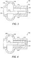
- an ORP generally identified by reference numeral 100, comprises a container 112, having first and second bores 114; 116, in fluid communication via a connecting portion 120.
- a piston 122 is slidably mounted within second bore 116.
- a flexible cover 126 is mounted over or secured to container 112, and is coupled to a free end 124, of piston 122.
- Flexible cover 126 encloses a chamber 128, within which is contained a fluid 130, which preferably may be a non-Newtonian dilatant fluid.
- Flexible cover 126 may be formed of an elastomeric material, such as silicone. Fluid 130, is free to be displaced, depending on the relative positioning of container 112, and piston 122.
- This embodiment is a construct having the fundamental properties of a mechanical damper, wherein the damping effect in ORP 100, increases with increasing frequency of input frequencies in the audible spectrum which produce small loading pressures of very short duration and which may further contribute to the stiffening derived from the intrinsic properties of the non-Newtonian dilatant fluid 130.
- ORP 100 is configured to span a gap in an ossicular chain of a patient, with piston head 144, and an end 146, of container 112, being secured to appropriate anatomical or prosthetic components within a patient's middle ear cavity. Accordingly, a load applied to ORP 100, will act so as to cause, or tend to cause, relative movement between piston 122, and container 112. In use, loads associated with sound pressure variations, which are low in magnitude and oscillatory in nature, result in substantially no movement of piston 122, relative to container 112, by virtue of the resistance to motion of the fluid within bores 114; 116. Accordingly, ORP 100, effectively becomes stiff when exposed to loading in the audio frequency range and as such permits sound induced vibrations to be transmitted across it.
- ORP 100 when ORP 100, is exposed to loads associated with variations in ambient pressures, which are large relative to those associated with sound pressure variations, and which, in addition, are applied generally in a single direction, ORP 100, is compliant (becomes deformable) because such loads are sufficient to overcome the resistance to motion of fluid 130, which is displaced along bores 114; 116.
- ORP 200 is also a construct having the fundamental properties of a mechanical damper and is substantially similar in many respects to the arrangement of ORP 100, immediately hereinbefore described with reference to Fig 3 .
- ORP 200 comprises a container 212, which incorporates three bores 214, 216, 218, which are in fluid communication with each other via a suitable connecting portion 220.
- a piston 222 is located within middle bore 218, and in use causes fluid 230, which is preferably although not exclusively a non-Newtonian fluid, to be displaced along outer bores 214, 218, which are in communication with chamber 228.
- the operation of ORP 200 is substantially similar to that shown in Fig 3 .
- Figure 12 is an alternative view of the ORP of Figs 2 , 3 or 4 , which shows the flexible cover 26/126 that contains the fluid which leaks past the piston 122/222.
- the movement resistance function of the respective ORPs 10; 100; 200 may be further reinforced by contact friction forces and inertial effects.
- these embodiments may be configured and positioned within the ossicular chain of a patient in a variety of ways, such as those immediately hereinafter described with reference to Figs 5 - 8 .
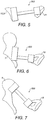
- an ORP generally identified by reference numeral 300, extends between the eardrum 12, or a residual part (not separately numbered) of the malleus 5, and the footplate 21, of the stapes 15, such that ORP 300, functions as a total ORP (usually referred to by those skilled in the art as a TORP).
- ORP 400 extends between the manubrium 7, of the malleus 5, and the stapes 15.
- ORP 400 is a partial ORP (usually referred to by those skilled in the art as a PORP).
- FIG 7 an alternative PORP, identified by reference numeral 500, is shown extending between the head 9, of the malleus 5, and the stapes 15.
- a further alternative PORP, 600, is shown in Fig 8 , extending between the body 13, of the incus 11, and the stapes 15.
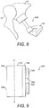
- ORP 700 comprises a container 712, closed by first and second end caps 746; 748.
- An axle 722 is rotatably mounted within container 712, into which it extends through first end cap 746.
- a first attachment point 740 is secured to a free end 724, of axle 722, located externally to container 712, and a second attachment point 742, is positioned on container 712.
- Attachment points 740; 742 provide securing means for securing ORP 700, between components within the auditory system of a patient. Accordingly, relative rotational motion of axle 722, and container 712, results in corresponding relative rotational motion of first and second attachment points 740; 742.
- FIG 10 there is shown a cross-sectional view of ORP 700, through line a - b, in Fig 9 .
- Container 712 is filled with fluid 730, which may be a Newtonian or a non-Newtonian fluid.
- Axle 722 carries a plurality of circumferentially distributed and radially extending vanes 750, which are configured to be rotated with axle 722.
- vanes 750 are each provided with a port or hole 754, adjacent to tip 752, thereof, whereby each hole 754, permits the passage of fluid 730, therethrough upon rotation of vanes 750, relative to container 712.
- vanes 750, container 712, and fluid 730 collectively define a rotational fluid damper which exhibits a stiffness characteristic which increases with increasing frequency of motion of the vane relative to the container.
- a non-Newtonian fluid is utilised, movement of the vanes in response to an applied static or dynamic force will affect the viscosity and thus the effective stiffness of the fluid damper which increases with increasing frequency of motion.
- axle 722 and container 712 may be provided.
- the rotational fluid damper mechanism of this embodiment can provide high resistance to motion at audio frequencies but compliance when subjected to quasistatic atmospheric pressure changes.
- Fig 11 is a view of ORP 700, in position and used as a PORP, in which ORP 700, is secured to the head 9, of the malleus 7.
- An extension arm 722 may extend between ORP 700, and the stapes 15, in order to bridge the gap in the ossicular chain.
- Extension arm 722 may comprise a rigid structure.
- extension arm 722 may comprise a linear ORP, such as an ORP hereinbefore described with reference to Figs 2 - 4 .
- First and second attachment points 740, 742 are mounted on respective opposing first and second end caps 744; 746, of container 712, thereby providing means for securing ORP 700, between components of the auditory system of a patient.
- First and second attachment points 740; 742 may be secured to anatomical components, prosthetic or otherwise artificial components of the auditory system.
- attachment points 740; 742 may be secured to components of the auditory system via wires, crimping means, clips, cement, glue, friction couplings or the like, or any suitable combination of fixing means (not illustrated).
- ORPs according to the principles of embodiments of the present invention described herein, whether they be TORPs or PORPs (or some other category of ossicular replacement prosthesis), would be capable of providing for movement of approximately ⁇ 0.5 mm to 1.0 mm deflection to accommodate the effects of low frequency changes associated with static and quasistatic pressure changes, whilst concomitantly providing a sufficiently rigid structure at audio frequencies to enable adequate transmission of vibrations to satisfy the clinical and consumer requirements of an ORP.
- references to sound and sound vibrations are references to vibrations whose frequencies lie between about 20 and 20 000 Hertz, and which thus lie within the range of perception of the human ear.
- References to static or quasi-static pressure variations refer to pressure which differs from normal ambient pressure by a constant amount, or which varies substantially more slowly than in sound vibrations. For example, slowly varying but high magnitude pressure changes that occur mainly due to changes in atmospheric pressure (but also passing through train tunnels, etc.) and which are substantially below the audio frequency range.
Description
- The present invention relates to an ossicular replacement prosthesis, and in particular, but not exclusively, to an ossicular replacement prosthesis incorporating a Newtonian or non-Newtonian fluid system.
- An ossicular replacement prosthesis (ORP) is a structure that replaces part or all of one or more of the three bones of the ossicular chain of the human middle ear. A schematic representation of the ossicular chain is shown in
Fig. 1 . The ossicular chain, generally represented byreference numeral 1, comprises three connected bones, called auditory ossicles, which extend across the middle ear from the tympanic membrane (eardrum) 3, to the oval window (not shown). The bones include themalleus 5, which has landmark portions known as the neck or handle (more strictly the manubrium) 7, and thehead 9; the incus 11, which includes abody portion 13; and thestapes 15. These bones are also known colloquially and respectively as the hammer, anvil and stirrup. Themalleus 5, engages theeardrum 3, and is articulated to the incus 11, via the incudomalleal joint (IMJ) 17. The incus 11, in turn, is articulated with thestapes 15, via the incudostapedial joint (ISJ) 19, and thefootplate 21, of thestapes 15, engages the oval window (not shown). Sound induced vibration of theeardrum 3, is thus transmitted across theossicular chain 1, to the cochlea (not shown) of the inner ear. - ORPs are used in ossicular chain reconstruction in cases where the normal process of sound conduction from the eardrum to the inner ear is impeded by a failure of part or all of the ossicular chain to transmit the vibrations generated from sound arriving at the eardrum. The ORP provides a sound conduction bridge across the gap created when the dysfunctional parts of the ossicular chain are removed.
- An ORP is implanted using a surgical procedure in which the middle ear is usually approached via the external ear canal and an incision is made around the eardrum which is then reflected to provide access to the middle ear cavity.
- ORPs are classified by some worker in this field as Total ORPs (TORPs) and Partial ORPs (PORPs), the former spanning the complete ossicular chain from the eardrum to the oval window and the latter spanning part of the ossicular chain. There are also acronyms for other types of PORP. For example a PORP that replaces an incus (an incus replacement prosthesis) may be referred to as an IRP. In addition, special prostheses for treating otosclerosis are used in stapedectomy surgery. However, the term ORP as used herein is intended to refer generally to any device which is used to replace part or all of the ossicular chain.
- An ORP must possess a number of properties in order to function effectively. For example, those parts which are exposed to the internal environment of the body and those in direct contact with body tissue must be biocompatible and chemically stable. Additionally, an ORP should be rigid enough and have sufficiently low mechanical damping to transmit acoustically derived vibrations with minimal or low loss of signal. Furthermore, an ORP
should not impart any more loading to the ossicular chain by virtue of its mass than is absolutely necessary or clinically acceptable. During its lifetime, which may be many years, an ORP may be subjected to billions of vibrating cycles in the audio frequency range and must, therefore, maintain its structure and function with minimal deterioration. - Existing ORPs are manufactured in a wide range of shapes and sizes, and are designed to span the gap left after the excision of a portion or all of the ossicular chain. ORPs have a wide range of end-fittings constituting attachment means for attachment to the bones at each side of the gap. There are various means used in ORPs for attachment to the ossicular chain, including, non-exhaustively, wires, spring clips and other components which may be crimped into place. These attachment means form part of the prosthesis and usually rely on a lock or a friction fit between the prosthesis and the tissue. Cements constitute generally less-preferred attachment means and very few of them are approved for use in the middle ear by regulatory bodies, such as the Food and Drug Administration in the USA. Bioactive materials, such as calcium hydroxyapatite (syn. hydroxylapatite), form a chemical bond between bone and the implant and may be used alone or in a hybrid form with another means of attachment.
- Some ORPs are offered in a considerable range of sizes whereas others are presented in only a few sizes or in a single size which can be modified to fit the patient intraoperatively by reshaping or by size reduction (cutting down). However, intraoperative modification may be difficult and time consuming.
- In addition to transforming sound into a suitable form of vibration to activate the cochlea in the inner ear, the middle ear also has means for compensating for large static, or quasistatic, variations in atmospheric pressure (alternatively herein termed ambient pressure) which could otherwise cause sufficiently large and potentially damaging displacements of the ossicular chain.
- Examples of commonly experienced effects of ambient pressure variations include passing into and out of a railway tunnel whilst on a train running at high speed, travelling in an aircraft during ascent and descent, underwater diving and nose-blowing. Compensation for ambient pressure changes is achieved by various means including the ability of the IMJ (17, in
Fig. 1 ) to move in such a manner that high levels of deflection of the eardrum passed to the malleus are not transmitted via the incus to the stapes. - Implantation of all TORPs and most PORPs involves removing the incus, thereby destroying the ISJ and IMJ, which, in turn, results in the loss of the motion-limiting compensation mechanism. Accordingly, an ORP which provides effective means for preventing large changes in atmospheric pressure leading to excessive motion at the stapes footplate (21 in
Fig. 1 ) is desirable. For example, a spring element forming part of an ORP could deflect under a force generated by a static pressure and so provide such compensating means. Examples of ORPs that employ spring elements are disclosed inUS Patent 6203571 B1 ,US Patent 4957507 ,US Patent 4624,672 ,WO 92/18066 FR 2691354 -
US Patent Application Publication 2003/0097178 discloses a middle ear prosthesis that is length-adjustable in a post-implantation period to accommodate tensions in tissue caused by healing. It is among the objects of embodiments of the present invention to seek to address these and other limitations in the prior art. - According to a first aspect of the present invention, there is provided an ossicular replacement prosthesis comprising a deformable coupling provided with first and second attachment points, being together configured to provide coupling means between anatomical, prosthetic or otherwise artificial components, or any suitable combination thereof disposed within the auditory system of a human patient such that when the deformable coupling is exposed to sound induced vibrations, for example originating from the tympanic membrane (eardrum), these vibrations may be transmitted across the coupling means with minimal acoustic damping or attenuation.
- In one embodiment of the present invention, presented as a TORP, the deformable coupling may be configured to replace all three ossicles of the ossicular chain so as to extend between the tympanic membrane and the oval window. In another embodiment of the present invention presented as a PORP, the deformable coupling may be configured to replace all or part of one or more (but less than the totality of all three) ossicles so as to bridge a gap in the ossicular chain.
- Preferably, the deformable coupling is selectively deformable and additionally is configured to deform in response to variations in local ambient pressure. Beneficially, deformation of the coupling in this manner permits relative movement between the first and second attachment points.
- It is well known that sound propagates as waves of alternating pressures of a dynamic or transient nature which deviate from the local ambient pressure. These dynamic sound pressure variations or acoustical pressure variations are detected by the auditory system and conducted across the middle ear as sound induced vibrations. Sound pressure variations generally impose minimal forces on the auditory system. However, changes in ambient pressure, which are generally of a static or quasistatic nature, can impart forces to the eardrum and ossicular chain which may be up to 10,000 times or more larger with the potential to cause much larger and possibly damaging deflections of the ossicular chain.
- Accordingly, the present invention advantageously permits sound induced vibrations to be transmitted across the deformable coupling with minimal acoustic damping or attenuation, while simultaneously permitting the coupling to deform in response to local ambient (high) pressure changes. In this way, the ORP of the present invention may operate as an effective acoustic transmission or conduction component while changes in ambient pressure will be damped or absorbed such that the effects of said ambient pressure changes will not be transmitted across the coupling, ultimately protecting the inner ear and other auditory system components of the patient.
- The deformable coupling of the ORP may permit relative rectilinear motion of the first and second attachment points. Alternatively, or additionally, the deformable coupling may be configured to be deformed to permit rotational motion between the first and second attachment points. Rectilinear and rotational deformation of the coupling may also facilitate the process of fixation of the first and second attachment points to components within the auditory system of the patient during implantation, thus eliminating or minimising the need for intraoperative adaptation.
- Preferably, the deformable coupling is of variable stiffness and more preferably, its stiffness varies in response to an external stimulant or condition, such that, for instance, it decreases in response to an increased applied load or force associated with ambient pressure increase.
- Preferably, the deformable coupling is configured to become sufficiently stiff or rigid when exposed to a dynamic load or force associated with sound pressure variations in the audio frequency range, such that in use it may transmit sound induced vibrations with minimal acoustic damping or attenuation.
- Advantageously, the deformable coupling may comprise means for exerting a pre-load between the first and second attachment points, which pre-load may act to induce tension or compression within the auditory system of the patient thereby enhancing effectiveness of the ORP. The pre-load may be provided by means of an elastic material covering all or part or the ORP or other elastic means within the ORP.
- According to a second aspect of the present invention, the deformable coupling contains a fluid selected in accordance with preferential hydrodynamic and other properties to provide a desirable stiffening response of the coupling when loading occurs between the first and second attachment points. The fluid may a be a Newtonian fluid or it may be a non-Newtonian fluid, such as a dilatant or shear-stiffening fluid. Non-Newtonian fluids exhibit nonlinear stress velocity behaviour which results in velocity/frequency dependent viscosity behaviour. Shear-stiffening fluids increase in viscosity with increasing shear rate at a given temperature and pressure; the shear rate increasing with velocity or frequency of motion so that the dilatant fluid of the ORP of the present invention preferentially exhibits an increase in stiffness as the input frequency increases.
- Alternatively, the non-Newtonian fluid may comprise a thixotropic fluid (also known as a shear-thinning, or pseudoplastic fluid), which exhibits a decrease in viscosity with increasing shear rate at a given temperature and pressure. Such fluids appear to be rigid at rest and subsequently fluidise when sheared. Accordingly, when the small forces caused by acoustical
sound waves are applied to the prosthesis of the present invention they will be of insufficient magnitude to shear the fluid which remains substantially rigid and capable of transmitting sound derived vibrations. - In marked contradistinction, loads associated with ambient pressure changes have sufficient magnitude to shear the thixotropic fluid so much that its viscosity is altered and it becomes more fluid allowing the deformable coupling to deform in response to the load introduced by larger ambient pressure variations which are thereby compensated. Pressure equalisation in response to ambient pressure change events is achieved via the Eustachian tube of the auditory system whereafter a thixotropic fluid would become rigid again.
- According to a third aspect of the present invention, there is provided an ossicular replacement prosthesis comprising a deformable coupling having first and second attachment points configured to be coupled between components within the auditory system of a patient, said deformable coupling comprising a fluid-filled container and having a flowpath, wherein interaction of fluid within the flowpath in response to a force applied on the deformable coupling permits the first and second attachment points to be substantially fixed relative to each other when the deformable coupling is exposed to sound induced vibrations.
- Preferably, the flowpath opens into a cavity formed within or adjacent to the container, wherein the flowpath is of a smaller cross-sectional dimension or capacity than that of the cavity. The cavity may be provided with a rigid or flexible boundary. In use, certain forces applied to the deformable coupling will cause the fluid to be displaced through or along the flowpath.
- Small loads derived from acoustical pressures are oscillatory and of short duration and when imparted to the deformable coupling are insufficient to overcome the fluid resistance within the flowpath and will not result in any significant movement of the fluid therethrough. However, forces resulting from static or quasistatic ambient pressure variations, which are generally applied in a single direction and are of relatively extended duration, are sufficient to displace the fluid and thus cause the coupling to deform. This effect may be reinforced by friction forces or mass effects within the coupling.
- In one embodiment of the present invention, the deformable coupling may comprise a piston slidably mounted within the container. The piston preferably extends externally to the container. The extending portion may be of the same diameter or effective width as that of the piston or it may have a different dimension. Preferably, a free end of the piston, located external to the container, may be one of the first and second attachment points. In addition, it is preferable that the other of the first and second attachment points is disposed on the container. Accordingly, relative movement of the first and second attachment points may be achieved by corresponding relative movement of the piston within the container. Beneficially, the piston is disposed within the container such that it interfaces with a fluid, preferably but not essentially a non-Newtonian fluid, also located within the container.
- Advantageously, the piston may divide the container into first and second cavities, wherein movement of the piston within the container results in a respective and corresponding volume change of the first and second cavities and the movement of fluid from one cavity to the other cavity. Fluid communication may be achieved via ports extending through the piston or,
advantageously, via ports in the container. Alternatively, or additionally, fluid communication may be achieved via a passage, which may be annular, disposed between the piston and an inner wall of the container. - Accordingly, the piston and container may advantageously collectively define a fluid damper which exhibits a stiffness characteristic that increases with increasing frequency of motion of the piston relative to the container. This stiffness characteristic may advantageously assist to permit the deformable coupling to become sufficiently stiff when exposed to audio frequency range derived forces, while becoming sufficiently flexible in response to loading from forces derived from the sub-audio range, such as from those pressures exerted on the eardrum of a patient resulting from static or quasistatic changes in ambient air pressure.
- Furthermore, advantage may be taken of the combination of stick-slip, the characteristics of the fluid within the container and the geometrical features of the piston and container, whereby the ORP of the present invention will effectively provide high resistance to motion at pressure variations associated with audio frequencies and compliance when subjected to pressures transmitted from the eardrum which might otherwise cause discomfort and even damage to structures of the middle ear and inner ear.
- The term "stick-slip" refers to an occurrence where two surfaces in contact or approximation may move with respect to one another only if the applied force is sufficient to overcome the frictional and surface contact forces that tend to prevent this movement.
- Advantageously, where the fluid within the container comprises a dilatant non-Newtonian fluid, movement of the piston in response to an applied static or dynamic force will affect the viscosity and thus the effective stiffness of said dilatant fluid. Accordingly, the stiffness of the fluid damper, defined by the piston and container, will increase with increasing frequency of motion which effect synergistically combines with the effect of the increasing stiffness of the non-Newtonian fluid with increasing frequency. This mutually reinforcing arrangement effectively provides a rapid increase in stiffness with increasing frequency, while permitting the deformable coupling to exhibit sufficiently low stiffness at the frequencies associated with static or quasistatic pressure changes and a sufficiently high stiffness at audio frequencies.
- The deformable coupling may incorporate a conduit or connecting portion extending between the first and second cavities of the container. The wall of the container preferably defines first and second ports, said first port adjacent said first cavity and said second port adjacent said second cavity, wherein the conduit extends between said first and second ports. Preferably, the piston is configured to be translated within the container between the ports, such that in use, movement of the piston displaces fluid between the first and second cavities via the connecting portion. The resistance to a fluid movement along the conduits or connecting portion may be provided according to the diameter or cross section of the connecting portion and its length.
- According to a fifth aspect of the present invention, there is provided an ORP wherein the deformable coupling may comprise a rotatable element rotatably mounted within the container. The rotatable element is preferably coupled to an axle which extends externally to the container. Preferably, the rotatable element comprises at least one vane mounted on the axle and radially extending therefrom. Advantageously, the first attachment point is provided on or adjacent an end of the axle positioned externally to the container, and the second attachment point is disposed upon the container. Accordingly, rotation of the axle relative to the container will result in relative rotational movement of the first and second attachment points. Advantageously, a flexible cover fixed at the container and circumferentially on the axle prevents any leakage of fluid or fluid vapour from contacting the tissues of the middle ear and isolates the ORP from contamination from tissues and body fluids. The flexibility of the cover is sufficient to allow relative rotational movement of the first and second attachment points and may be made of a material and shape that provides means to exert a pre-load between the first and second attachment points, which pre-load may act to induce tension or compression within the auditory system of the patient thereby enhancing effectiveness of the ORP. The pre-load may be provided by means of an elastic material covering part or all or the ORP or by other elastic means within the ORP.
- Beneficially, the at least one vane is disposed within the container and is configured so as to engage and interface with a fluid contained therein. Preferably, but not essentially, the fluid is a non-Newtonian fluid and the vane is configured by, for example holes or ports or the like, provided therein such that in use, fluid is permitted to pass therethrough. Alternatively, or additionally, the vanes may be disposed within the container and arranged so as to permit fluid to pass over said vanes. For example, the vanes may be
so disposed such that the tips thereof or both the tips and the edges thereof may approximate the inner surface of the container so as to define a gap. - Accordingly, the vane and container may advantageously collectively define a rotational fluid damper which exhibits a stiffness characteristic that increases with increasing frequency of motion of the vane relative to the container. This stiffness characteristic may advantageously assist to permit the deformable coupling to become sufficiently stiff when exposed to forces derived from acoustical vibrations in the audio frequency range, while becoming sufficiently flexible in response to forces derived from static or quasistatic changes in ambient air pressure.
- Advantageously, where the fluid within the container comprises a non-Newtonian fluid, movement of the vanes in response to an applied static or dynamic force will affect the viscosity and thus effective stiffness of said non-Newtonian fluid. Accordingly, the increasing stiffness of the fluid damper defined by the vanes and container with increasing frequency of motion combines with the effect of the increasing stiffness of the non-Newtonian fluid with increasing frequency. Furthermore, as noted above, advantage may be taken of the combination of stick-slip and the resistance to motion of the fluid within the rotational damper.
- According to a sixth aspect of the present invention, there is provided an ORP wherein the deformable coupling comprises first and second friction elements coupled together via a friction coupling, wherein the first friction element supports the first attachment point and the second friction element supports the second attachment point. Advantageously, the friction coupling is created by an interference fit between portions of the first and second friction elements. Advantageously, relative movement between the first and second elements is achievable when said elements are exposed to a force sufficient to overcome the stick-slip effect or static friction of the interference fit. Advantageously, the friction elements collectively operate to provide a stick-slip effect with a high resistance to the small forces associated with and derived from normal audio frequencies such that these forces are too low to overcome the static friction of the interference fit, resulting in an effective rigid coupling, while the higher forces arising from quasistatic pressures on the eardrum overcome the static friction of the interference connection and allow relative movement of the elements.
- These and other aspects of the present invention will now be described, by way of example only, with reference to the accompanying drawings, in which:
-
Figure 1 , is a diagrammatic representation of the human ossicular chain and component structures thereof; -
Figure 2 , is a diagrammatic representation of a first preferred embodiment of an ORP according to the present invention in which the principle of operation depends upon a construct which allows leakage of fluid past a piston in a bore; -
Figure 3 , is a diagrammatic representation of a second preferred embodiment of an ORP according to the present invention in which the principle of operation depends upon provision of a construct which allows fluid and a plurality of chambers to cooperate as a mechanical damper; -
Figure 4 , is a diagrammatic representation of a further preferred embodiment of an ORP according to the present invention in which is provided a further mechanical damper; -
Figures 5 to 8 , are diagrammatic representations of different configurations of the embodiments ofFigs 2 - 4 ; -
Figure 9 , is a diagrammatic representation of a further preferred embodiment of an ORP according to the present invention in which a deformable coupling deforms by rotation, wherein fluid, a container and at least one vane cooperate to function as a rotational fluid damper; -
Figure 10 , is a cross-sectional view of the ORP ofFig 9 , through line a - b; -
Figure 11 , is a view of the ORP illustrated inFig 9 and10 , configured as a PORP and in position within a human patient; -
Figure 12 is an alternative view of the ORP ofFigs 2 ,3 or 4 . - In the following description
Figs 2 - 11 , refer to preferred embodiments of an ORP having the respectivegeneral designations - A first preferred embodiment of the present invention is shown in
Fig 2 , of the drawings in whichORP 10, comprises acontainer 12, having asingle bore 14, within which is slidably mounted apiston 22. Aflexible cover 26, is secured tocontainer 12, and to afree end 24, ofpiston 22, so as to enclose achamber 28, filled withfluid 30, which is preferably a non-Newtonian dilatant fluid.Piston 22, defines anannular clearance 32, betweenpiston 22, and bore 14, such thatfluid 30, may be displaced throughannular clearance 32, betweenbore 14, andchamber 28. Accordingly, the resistance offluid 30, acrossannular clearance 32, in response to the type of loading applied onORP 10, will affect changes to the effective stiffness thereof. It is to be noted that this construct and operational mode ofORP 10, obviates the need for fluid-sealing means betweenpiston 22, andcontainer 12. Indeed, the fundamental principal of operation requires thatfluid 30, leaks pastpiston 22.Flexible cover 26, ensures integrity offluid 30, inchamber 28. This configuration simplifies the structure of the ORP. Moreover, this configuration eliminates the risk of leakage of fluid and the ingress of biological matter, seen with standard piston to cylinder seals. -
ORP 10, has first and second attachment points 40; 42, for non-releasable attachment to suitable sites on anatomical structures and prosthetic or otherwise artificial components of the auditory system. Attachment points 40; 42, may be secured to components of the auditory system via wires, crimping means, clips, cement, glue, friction couplings or the like, or any suitable combination of fixing means (none of these are illustrated). - In
Fig 3 , there is shown a diagrammatic representation of a second preferred embodiment of the present invention wherein an ORP, generally identified byreference numeral 100, comprises acontainer 112, having first andsecond bores 114; 116, in fluid communication via a connectingportion 120. Apiston 122, is slidably mounted withinsecond bore 116. Aflexible cover 126, is mounted over or secured tocontainer 112, and is coupled to afree end 124, ofpiston 122.Flexible cover 126, encloses achamber 128, within which is contained a fluid 130, which preferably may be a non-Newtonian dilatant fluid. -
Flexible cover 126, may be formed of an elastomeric material, such as silicone.Fluid 130, is free to be displaced, depending on the relative positioning ofcontainer 112, andpiston 122. This embodiment is a construct having the fundamental properties of a mechanical damper, wherein the damping effect inORP 100, increases with increasing frequency of input frequencies in the audible spectrum which produce small loading pressures of very short duration and which may further contribute to the stiffening derived from the intrinsic properties of the non-Newtoniandilatant fluid 130. -
ORP 100, is configured to span a gap in an ossicular chain of a patient, withpiston head 144, and anend 146, ofcontainer 112, being secured to appropriate anatomical or prosthetic components within a patient's middle ear cavity. Accordingly, a load applied toORP 100, will act so as to cause, or tend to cause, relative movement betweenpiston 122, andcontainer 112. In use, loads associated with sound pressure variations, which are low in magnitude and oscillatory in nature, result in substantially no movement ofpiston 122, relative tocontainer 112, by virtue of the resistance to motion of the fluid withinbores 114; 116. Accordingly,ORP 100, effectively becomes stiff when exposed to loading in the audio frequency range and as such permits sound induced vibrations to be transmitted across it. - However, when
ORP 100, is exposed to loads associated with variations in ambient pressures, which are large relative to those associated with sound pressure variations, and which, in addition, are applied generally in a single direction,ORP 100, is compliant (becomes deformable) because such loads are sufficient to overcome the resistance to motion offluid 130, which is displaced alongbores 114; 116. - Turning now to
Fig 4 , there is illustrated a further preferred embodiment of an ORP according to the present invention and generally identified byreference numeral 200.ORP 200, is also a construct having the fundamental properties of a mechanical damper and is substantially similar in many respects to the arrangement ofORP 100, immediately hereinbefore described with reference toFig 3 . In this embodiment,ORP 200, comprises acontainer 212, which incorporates threebores portion 220. Apiston 222, is located withinmiddle bore 218, and in use causesfluid 230, which is preferably although not exclusively a non-Newtonian fluid, to be displaced alongouter bores chamber 228. The operation ofORP 200 is substantially similar to that shown inFig 3 . -
Figure 12 is an alternative view of the ORP ofFigs 2 ,3 or 4 , which shows theflexible cover 26/126 that contains the fluid which leaks past thepiston 122/222. - In the embodiments illustrated with reference to
Figs 2 - 4 , the movement resistance function of therespective ORPs 10; 100; 200, may be further reinforced by contact friction forces and inertial effects. Furthermore, these embodiments may be configured and positioned within the ossicular chain of a patient in a variety of ways, such as those immediately hereinafter described with reference toFigs 5 - 8 . - In
Fig 5 , an ORP, generally identified byreference numeral 300, extends between theeardrum 12, or a residual part (not separately numbered) of themalleus 5, and thefootplate 21, of thestapes 15, such thatORP 300, functions as a total ORP (usually referred to by those skilled in the art as a TORP). - In
Fig 6 , an ORP, in this case identified byreference numeral 400, extends between the manubrium 7, of themalleus 5, and the stapes 15. In this case,ORP 400, is a partial ORP (usually referred to by those skilled in the art as a PORP). - In
Fig 7 , an alternative PORP, identified byreference numeral 500, is shown extending between thehead 9, of themalleus 5, and the stapes 15. - A further alternative PORP, 600, is shown in
Fig 8 , extending between thebody 13, of the incus 11, and the stapes 15. - Reference is now made to
Fig 9 , of the drawings in which there is shown a side view of an ORP, generally identified byreference numeral 700, which is a further preferred embodiment of the present invention.ORP 700, comprises acontainer 712, closed by first and second end caps 746; 748. Anaxle 722, is rotatably mounted withincontainer 712, into which it extends throughfirst end cap 746. Afirst attachment point 740, is secured to afree end 724, ofaxle 722, located externally tocontainer 712, and asecond attachment point 742, is positioned oncontainer 712. Attachment points 740; 742, provide securing means for securingORP 700, between components within the auditory system of a patient. Accordingly, relative rotational motion ofaxle 722, andcontainer 712, results in corresponding relative rotational motion of first and second attachment points 740; 742. - Turning to
Fig 10 , there is shown a cross-sectional view ofORP 700, through line a - b, inFig 9 .Container 712, is filled withfluid 730, which may be a Newtonian or a non-Newtonian fluid.Axle 722, carries a plurality of circumferentially distributed and radially extendingvanes 750, which are configured to be rotated withaxle 722. In this embodiment,vanes 750, are each provided with a port orhole 754, adjacent to tip 752, thereof, whereby eachhole 754, permits the passage offluid 730, therethrough upon rotation ofvanes 750, relative tocontainer 712. Accordingly,vanes 750,container 712, andfluid 730, collectively define a rotational fluid damper which exhibits a stiffness characteristic which increases with increasing frequency of motion of the vane relative to the container. Where a non-Newtonian fluid is utilised, movement of the vanes in response to an applied static or dynamic force will affect the viscosity and thus the effective stiffness of the fluid damper which increases with increasing frequency of motion. - In certain embodiments a seal between
axle 722 andcontainer 712 may be provided. - Furthermore, advantage may be taken of the combination of stick-slip and the resistance to motion of the fluid within the damper through selection of a suitable fluid and careful design of the geometrical features of the damper components. By these means, the rotational fluid damper mechanism of this embodiment can provide high resistance to motion at audio frequencies but compliance when subjected to quasistatic atmospheric pressure changes.
-
Fig 11 , is a view ofORP 700, in position and used as a PORP, in whichORP 700, is secured to thehead 9, of the malleus 7. Anextension arm 722, may extend betweenORP 700, and thestapes 15, in order to bridge the gap in the ossicular chain.Extension arm 722, may comprise a rigid structure. Alternatively, or additionally,extension arm 722, may comprise a linear ORP, such as an ORP hereinbefore described with reference toFigs 2 - 4 . - First and second attachment points 740, 742, are mounted on respective opposing first and second end caps 744; 746, of
container 712, thereby providing means for securingORP 700, between components of the auditory system of a patient. First and second attachment points 740; 742, may be secured to anatomical components, prosthetic or otherwise artificial components of the auditory system. Although not shown, attachment points 740; 742, may be secured to components of the auditory system via wires, crimping means, clips, cement, glue, friction couplings or the like, or any suitable combination of fixing means (not illustrated). - Suitably designed ORPs according to the principles of embodiments of the present invention described herein, whether they be TORPs or PORPs (or some other category of ossicular replacement prosthesis), would be capable of providing for movement of approximately ± 0.5 mm to 1.0 mm deflection to accommodate the effects of low frequency changes associated with static and quasistatic pressure changes, whilst concomitantly providing a sufficiently rigid structure at audio frequencies to enable adequate transmission of vibrations to satisfy the clinical and consumer requirements of an ORP.
- It should be understood that the embodiments described are merely exemplary and that various modifications may be made without departing from the scope of the present invention.
- In the present specification, references to sound and sound vibrations are references to vibrations whose frequencies lie between about 20 and 20 000 Hertz, and which thus lie within the range of perception of the human ear. References to static or quasi-static pressure variations refer to pressure which differs from normal ambient pressure by a constant amount, or which varies substantially more slowly than in sound vibrations. For example, slowly varying but high magnitude pressure changes that occur mainly due to changes in atmospheric pressure (but also passing through train tunnels, etc.) and which are substantially below the audio frequency range.
Claims (7)
- An ossicular replacement prosthesis (ORP) (10) for coupling a first point to a second point in the middle ear of a patient, to replace all or part of the ossicular chain,
the ORP comprising a coupling having a variable configuration for accounting for pressure differentials, said coupling comprising a fluid filled chamber (28); wherein the chamber (28) comprises a container (12) which defines a bore (14), and a piston (22) slidably mounted in the bore (14) for varying the configuration of the coupling;
wherein an annular clearance (32) is defined between the piston (22) and the container (12) for permitting displacement of the fluid within the chamber (28), the relative movement of the container (12) and the piston (22) being controlled by the movement of the fluid in said chamber (28),
wherein said chamber (28) is configured to restrict the displacement of the fluid such that relative movement of the container (12) and the piston (22) is permitted in response to quasi-static changes in pressure, and is substantially prevented in response to vibrational changes corresponding to sound frequencies. - An ORP as claimed in claim 1, wherein said fluid is a Newtonian fluid or a non-Newtonian fluid, wherein said non-Newtonian fluid is a dilatant fluid or a thixotropic fluid.
- An ORP as claimed in claim 1 or 2, wherein said coupling is adapted to be deformed to permit relative rectilinear motion between said first and second points and/or to permit relative rotational motion between said first and second points.
- An ORP as claimed in any preceding claim, wherein stiffness of said coupling is variable.
- An ORP as claimed in any preceding claim, wherein stiffness of said coupling is variable in response to variations in the frequency and/or the magnitude of an applied load.
- An ORP as claimed in any preceding claim, wherein stiffness of said coupling increases in response to an increasing frequency of an applied load an/or decreases in response to an increasing magnitude of an applied load.
- An ORP as claimed in any preceding claim, wherein said coupling is adapted to exert a pre-load between said first and second points.
Applications Claiming Priority (2)
| Application Number | Priority Date | Filing Date | Title |
|---|---|---|---|
| GBGB0704125.4A GB0704125D0 (en) | 2007-03-03 | 2007-03-03 | Ossicular replacement prosthesis |
| PCT/GB2008/050147 WO2008107716A1 (en) | 2007-03-03 | 2008-03-03 | Ossicular replacement prosthesis |
Publications (2)
| Publication Number | Publication Date |
|---|---|
| EP2134298A1 EP2134298A1 (en) | 2009-12-23 |
| EP2134298B1 true EP2134298B1 (en) | 2018-01-10 |
Family
ID=37965854
Family Applications (1)
| Application Number | Title | Priority Date | Filing Date |
|---|---|---|---|
| EP08709667.3A Active EP2134298B1 (en) | 2007-03-03 | 2008-03-03 | Ossicular replacement prosthesis |
Country Status (8)
| Country | Link |
|---|---|
| US (1) | US8920496B2 (en) |
| EP (1) | EP2134298B1 (en) |
| JP (1) | JP5545956B2 (en) |
| CN (1) | CN101677858B (en) |
| AU (1) | AU2008222478B2 (en) |
| CA (1) | CA2717361A1 (en) |
| GB (1) | GB0704125D0 (en) |
| WO (1) | WO2008107716A1 (en) |
Families Citing this family (79)
| Publication number | Priority date | Publication date | Assignee | Title |
|---|---|---|---|---|
| US8603180B2 (en) | 2006-02-27 | 2013-12-10 | Biomet Manufacturing, Llc | Patient-specific acetabular alignment guides |
| US20080257363A1 (en) * | 2007-04-17 | 2008-10-23 | Biomet Manufacturing Corp. | Method And Apparatus For Manufacturing An Implant |
| US20150335438A1 (en) | 2006-02-27 | 2015-11-26 | Biomet Manufacturing, Llc. | Patient-specific augments |
| US9289253B2 (en) | 2006-02-27 | 2016-03-22 | Biomet Manufacturing, Llc | Patient-specific shoulder guide |
| US8092465B2 (en) | 2006-06-09 | 2012-01-10 | Biomet Manufacturing Corp. | Patient specific knee alignment guide and associated method |
| US8473305B2 (en) | 2007-04-17 | 2013-06-25 | Biomet Manufacturing Corp. | Method and apparatus for manufacturing an implant |
| US9113971B2 (en) | 2006-02-27 | 2015-08-25 | Biomet Manufacturing, Llc | Femoral acetabular impingement guide |
| US10278711B2 (en) | 2006-02-27 | 2019-05-07 | Biomet Manufacturing, Llc | Patient-specific femoral guide |
| US9339278B2 (en) | 2006-02-27 | 2016-05-17 | Biomet Manufacturing, Llc | Patient-specific acetabular guides and associated instruments |
| US8608749B2 (en) | 2006-02-27 | 2013-12-17 | Biomet Manufacturing, Llc | Patient-specific acetabular guides and associated instruments |
| US8241293B2 (en) * | 2006-02-27 | 2012-08-14 | Biomet Manufacturing Corp. | Patient specific high tibia osteotomy |
| US8377066B2 (en) | 2006-02-27 | 2013-02-19 | Biomet Manufacturing Corp. | Patient-specific elbow guides and associated methods |
| US9907659B2 (en) | 2007-04-17 | 2018-03-06 | Biomet Manufacturing, Llc | Method and apparatus for manufacturing an implant |
| US8568487B2 (en) | 2006-02-27 | 2013-10-29 | Biomet Manufacturing, Llc | Patient-specific hip joint devices |
| US8535387B2 (en) | 2006-02-27 | 2013-09-17 | Biomet Manufacturing, Llc | Patient-specific tools and implants |
| US9918740B2 (en) | 2006-02-27 | 2018-03-20 | Biomet Manufacturing, Llc | Backup surgical instrument system and method |
| US7967868B2 (en) | 2007-04-17 | 2011-06-28 | Biomet Manufacturing Corp. | Patient-modified implant and associated method |
| US8133234B2 (en) * | 2006-02-27 | 2012-03-13 | Biomet Manufacturing Corp. | Patient specific acetabular guide and method |
| US8608748B2 (en) | 2006-02-27 | 2013-12-17 | Biomet Manufacturing, Llc | Patient specific guides |
| US8591516B2 (en) | 2006-02-27 | 2013-11-26 | Biomet Manufacturing, Llc | Patient-specific orthopedic instruments |
| US8864769B2 (en) | 2006-02-27 | 2014-10-21 | Biomet Manufacturing, Llc | Alignment guides with patient-specific anchoring elements |
| US9173661B2 (en) | 2006-02-27 | 2015-11-03 | Biomet Manufacturing, Llc | Patient specific alignment guide with cutting surface and laser indicator |
| US8407067B2 (en) | 2007-04-17 | 2013-03-26 | Biomet Manufacturing Corp. | Method and apparatus for manufacturing an implant |
| US9345548B2 (en) | 2006-02-27 | 2016-05-24 | Biomet Manufacturing, Llc | Patient-specific pre-operative planning |
| US8858561B2 (en) | 2006-06-09 | 2014-10-14 | Blomet Manufacturing, LLC | Patient-specific alignment guide |
| US9795399B2 (en) | 2006-06-09 | 2017-10-24 | Biomet Manufacturing, Llc | Patient-specific knee alignment guide and associated method |
| DE102009028503B4 (en) | 2009-08-13 | 2013-11-14 | Biomet Manufacturing Corp. | Resection template for the resection of bones, method for producing such a resection template and operation set for performing knee joint surgery |
| US8632547B2 (en) | 2010-02-26 | 2014-01-21 | Biomet Sports Medicine, Llc | Patient-specific osteotomy devices and methods |
| US9271744B2 (en) | 2010-09-29 | 2016-03-01 | Biomet Manufacturing, Llc | Patient-specific guide for partial acetabular socket replacement |
| US9968376B2 (en) | 2010-11-29 | 2018-05-15 | Biomet Manufacturing, Llc | Patient-specific orthopedic instruments |
| EP2665444B1 (en) * | 2011-01-17 | 2018-03-14 | Coloplast A/S | Penile implant with dilatant liquid |
| US8419612B2 (en) | 2011-01-17 | 2013-04-16 | Coloplast A/S | Method treating erectile dysfunction via a penile implant with dilatant liquid |
| US8147400B1 (en) | 2011-01-17 | 2012-04-03 | Coloplast A/S | Penile implant with dilatant liquid |
| US9241745B2 (en) | 2011-03-07 | 2016-01-26 | Biomet Manufacturing, Llc | Patient-specific femoral version guide |
| US8715289B2 (en) | 2011-04-15 | 2014-05-06 | Biomet Manufacturing, Llc | Patient-specific numerically controlled instrument |
| US9675400B2 (en) | 2011-04-19 | 2017-06-13 | Biomet Manufacturing, Llc | Patient-specific fracture fixation instrumentation and method |
| US8956364B2 (en) | 2011-04-29 | 2015-02-17 | Biomet Manufacturing, Llc | Patient-specific partial knee guides and other instruments |
| US8668700B2 (en) | 2011-04-29 | 2014-03-11 | Biomet Manufacturing, Llc | Patient-specific convertible guides |
| US8532807B2 (en) | 2011-06-06 | 2013-09-10 | Biomet Manufacturing, Llc | Pre-operative planning and manufacturing method for orthopedic procedure |
| US9084618B2 (en) | 2011-06-13 | 2015-07-21 | Biomet Manufacturing, Llc | Drill guides for confirming alignment of patient-specific alignment guides |
| US8764760B2 (en) | 2011-07-01 | 2014-07-01 | Biomet Manufacturing, Llc | Patient-specific bone-cutting guidance instruments and methods |
| US20130001121A1 (en) | 2011-07-01 | 2013-01-03 | Biomet Manufacturing Corp. | Backup kit for a patient-specific arthroplasty kit assembly |
| US8597365B2 (en) | 2011-08-04 | 2013-12-03 | Biomet Manufacturing, Llc | Patient-specific pelvic implants for acetabular reconstruction |
| US9295497B2 (en) | 2011-08-31 | 2016-03-29 | Biomet Manufacturing, Llc | Patient-specific sacroiliac and pedicle guides |
| US9066734B2 (en) | 2011-08-31 | 2015-06-30 | Biomet Manufacturing, Llc | Patient-specific sacroiliac guides and associated methods |
| US9386993B2 (en) | 2011-09-29 | 2016-07-12 | Biomet Manufacturing, Llc | Patient-specific femoroacetabular impingement instruments and methods |
| US9554910B2 (en) | 2011-10-27 | 2017-01-31 | Biomet Manufacturing, Llc | Patient-specific glenoid guide and implants |
| US9451973B2 (en) | 2011-10-27 | 2016-09-27 | Biomet Manufacturing, Llc | Patient specific glenoid guide |
| US9301812B2 (en) | 2011-10-27 | 2016-04-05 | Biomet Manufacturing, Llc | Methods for patient-specific shoulder arthroplasty |
| KR20130046336A (en) | 2011-10-27 | 2013-05-07 | 삼성전자주식회사 | Multi-view device of display apparatus and contol method thereof, and display system |
| EP2770918B1 (en) | 2011-10-27 | 2017-07-19 | Biomet Manufacturing, LLC | Patient-specific glenoid guides |
| US9237950B2 (en) | 2012-02-02 | 2016-01-19 | Biomet Manufacturing, Llc | Implant with patient-specific porous structure |
| US9204977B2 (en) | 2012-12-11 | 2015-12-08 | Biomet Manufacturing, Llc | Patient-specific acetabular guide for anterior approach |
| US9060788B2 (en) | 2012-12-11 | 2015-06-23 | Biomet Manufacturing, Llc | Patient-specific acetabular guide for anterior approach |
| US11095994B2 (en) * | 2013-02-15 | 2021-08-17 | Cochlear Limited | Conformable pad bone conduction device |
| US9839438B2 (en) | 2013-03-11 | 2017-12-12 | Biomet Manufacturing, Llc | Patient-specific glenoid guide with a reusable guide holder |
| US9579107B2 (en) | 2013-03-12 | 2017-02-28 | Biomet Manufacturing, Llc | Multi-point fit for patient specific guide |
| US9498233B2 (en) | 2013-03-13 | 2016-11-22 | Biomet Manufacturing, Llc. | Universal acetabular guide and associated hardware |
| US9826981B2 (en) | 2013-03-13 | 2017-11-28 | Biomet Manufacturing, Llc | Tangential fit of patient-specific guides |
| US9517145B2 (en) | 2013-03-15 | 2016-12-13 | Biomet Manufacturing, Llc | Guide alignment system and method |
| US20150112349A1 (en) | 2013-10-21 | 2015-04-23 | Biomet Manufacturing, Llc | Ligament Guide Registration |
| US10282488B2 (en) | 2014-04-25 | 2019-05-07 | Biomet Manufacturing, Llc | HTO guide with optional guided ACL/PCL tunnels |
| US9408616B2 (en) | 2014-05-12 | 2016-08-09 | Biomet Manufacturing, Llc | Humeral cut guide |
| US9561040B2 (en) | 2014-06-03 | 2017-02-07 | Biomet Manufacturing, Llc | Patient-specific glenoid depth control |
| US9839436B2 (en) | 2014-06-03 | 2017-12-12 | Biomet Manufacturing, Llc | Patient-specific glenoid depth control |
| US10805744B2 (en) * | 2014-08-28 | 2020-10-13 | Cochlear Limited | Systems for accommodating separation of body parts in auditory prostheses |
| US9833245B2 (en) | 2014-09-29 | 2017-12-05 | Biomet Sports Medicine, Llc | Tibial tubercule osteotomy |
| US9826994B2 (en) | 2014-09-29 | 2017-11-28 | Biomet Manufacturing, Llc | Adjustable glenoid pin insertion guide |
| US9820868B2 (en) | 2015-03-30 | 2017-11-21 | Biomet Manufacturing, Llc | Method and apparatus for a pin apparatus |
| US10568647B2 (en) | 2015-06-25 | 2020-02-25 | Biomet Manufacturing, Llc | Patient-specific humeral guide designs |
| US10226262B2 (en) | 2015-06-25 | 2019-03-12 | Biomet Manufacturing, Llc | Patient-specific humeral guide designs |
| CN108886663B (en) * | 2016-03-29 | 2021-09-03 | Med-El电气医疗器械有限公司 | S-shaped coupling spring for middle ear implant |
| US10595990B2 (en) | 2016-09-06 | 2020-03-24 | Gyrus Acmi, Inc. | Osseointegrative adjustable ossicular prosthesis |
| US10722310B2 (en) | 2017-03-13 | 2020-07-28 | Zimmer Biomet CMF and Thoracic, LLC | Virtual surgery planning system and method |
| EP3595475B1 (en) * | 2017-04-17 | 2021-04-07 | Hewlett-Packard Development Company, L.P. | Vibrators in cells for footwear |
| CN108710775B (en) * | 2018-07-31 | 2021-05-25 | 东北大学 | Auditory ossicle chain transmission mechanism-based damping system and design method |
| KR102299713B1 (en) | 2019-12-16 | 2021-09-07 | 인제대학교 산학협력단 | Replacement prosthesis for auditory ossicle |
| US11819412B2 (en) | 2020-02-04 | 2023-11-21 | Coloplast A/S | Penile prostheses for treatment of erectile dysfunction |
| CN115836933B (en) * | 2023-02-17 | 2023-09-01 | 北京理贝尔生物工程研究所有限公司 | Intervertebral fusion device |
Family Cites Families (73)
| Publication number | Priority date | Publication date | Assignee | Title |
|---|---|---|---|---|
| US2394569A (en) | 1941-07-14 | 1946-02-12 | Dictograph Products Co Inc | Fitting hearing aid device |
| US3277433A (en) | 1963-10-17 | 1966-10-04 | William J Toulis | Flexural-extensional electromechanical transducer |
| US3594514A (en) | 1970-01-02 | 1971-07-20 | Medtronic Inc | Hearing aid with piezoelectric ceramic element |
| US3710399A (en) | 1970-06-23 | 1973-01-16 | H Hurst | Ossicle replacement prosthesis |
| US3764748A (en) | 1972-05-19 | 1973-10-09 | J Branch | Implanted hearing aids |
| US4118599A (en) | 1976-02-27 | 1978-10-03 | Victor Company Of Japan, Limited | Stereophonic sound reproduction system |
| JPS52125301A (en) | 1976-04-13 | 1977-10-21 | Victor Co Of Japan Ltd | Signal processing circuit |
| JPS53114201U (en) | 1977-02-18 | 1978-09-11 | ||
| DE2844979C2 (en) | 1978-10-16 | 1989-08-31 | Juval Dr.-Ing. 8000 München Mantel | Hearing aid |
| JPS60154800A (en) | 1984-01-24 | 1985-08-14 | Eastern Electric Kk | Hearing aid |
| US4624672A (en) | 1984-03-15 | 1986-11-25 | Edmundas Lenkauskas | Coiled wire prosthesis for complete or partial ossicular reconstruction |
| JPS6142284A (en) | 1984-08-03 | 1986-02-28 | Nec Kansai Ltd | Displacement increasing device |
| US4729366A (en) | 1984-12-04 | 1988-03-08 | Medical Devices Group, Inc. | Implantable hearing aid and method of improving hearing |
| US4601723A (en) | 1985-01-29 | 1986-07-22 | Mcgrew Robert N | Telescoping self-adjusting ossicular prostheses |
| DE3508830A1 (en) | 1985-03-13 | 1986-09-18 | Robert Bosch Gmbh, 7000 Stuttgart | Hearing aid |
| US5015225A (en) | 1985-05-22 | 1991-05-14 | Xomed, Inc. | Implantable electromagnetic middle-ear bone-conduction hearing aid device |
| US4774515A (en) | 1985-09-27 | 1988-09-27 | Bo Gehring | Attitude indicator |
| US4759070A (en) | 1986-05-27 | 1988-07-19 | Voroba Technologies Associates | Patient controlled master hearing aid |
| EP0349599B2 (en) | 1987-05-11 | 1995-12-06 | Jay Management Trust | Paradoxical hearing aid |
| US4809708A (en) | 1987-08-12 | 1989-03-07 | Nicolet Instrument Corporation | Method and apparatus for real bar measurements |
| US4957507A (en) | 1987-12-14 | 1990-09-18 | Edmundas Lenkauskas | Wire spring prosthesis for ossicular reconstruction |
| US4845688A (en) | 1988-03-21 | 1989-07-04 | Image Acoustics, Inc. | Electro-mechanical transduction apparatus |
| US4901353A (en) | 1988-05-10 | 1990-02-13 | Minnesota Mining And Manufacturing Company | Auditory prosthesis fitting using vectors |
| US4957478A (en) | 1988-10-17 | 1990-09-18 | Maniglia Anthony J | Partially implantable hearing aid device |
| US5303306A (en) | 1989-06-06 | 1994-04-12 | Audioscience, Inc. | Hearing aid with programmable remote and method of deriving settings for configuring the hearing aid |
| IT1248737B (en) | 1990-06-07 | 1995-01-26 | Franco Beoni | MEDIUM EAR PROSTHESIS |
| DE4104359A1 (en) | 1991-02-13 | 1992-08-20 | Implex Gmbh | CHARGING SYSTEM FOR IMPLANTABLE HOERHILFEN AND TINNITUS MASKERS |
| FR2675372B1 (en) | 1991-04-19 | 1998-12-18 | Guy Charvin | SELF-ADJUSTABLE OSSICULAR PROSTHESIS OF THE MIDDLE EAR. |
| US5233665A (en) | 1991-12-17 | 1993-08-03 | Gary L. Vaughn | Phonetic equalizer system |
| US5173944A (en) | 1992-01-29 | 1992-12-22 | The United States Of America As Represented By The Administrator Of The National Aeronautics And Space Administration | Head related transfer function pseudo-stereophony |
| FR2691354A1 (en) | 1992-05-22 | 1993-11-26 | France Chirurgie Instr | Mechanical prosthesis for middle ear bones - comprises metal wire bent to define part-rigid, part-flexible shaft linking drum component to bearing surface of stirrup bone |
| US5531787A (en) | 1993-01-25 | 1996-07-02 | Lesinski; S. George | Implantable auditory system with micromachined microsensor and microactuator |
| JP2606069B2 (en) | 1993-04-22 | 1997-04-30 | 日本電気株式会社 | Piezoelectric element displacement amplification mechanism and driving method thereof |
| US5325436A (en) | 1993-06-30 | 1994-06-28 | House Ear Institute | Method of signal processing for maintaining directional hearing with hearing aids |
| US5913815A (en) | 1993-07-01 | 1999-06-22 | Symphonix Devices, Inc. | Bone conducting floating mass transducers |
| US5456654A (en) | 1993-07-01 | 1995-10-10 | Ball; Geoffrey R. | Implantable magnetic hearing aid transducer |
| US5436975A (en) | 1994-02-02 | 1995-07-25 | Qsound Ltd. | Apparatus for cross fading out of the head sound locations |
| US5825894A (en) | 1994-08-17 | 1998-10-20 | Decibel Instruments, Inc. | Spatialization for hearing evaluation |
| RU2096027C1 (en) | 1995-06-05 | 1997-11-20 | Юрий Петрович Ульянов | Method for improving audition |
| US5729077A (en) | 1995-12-15 | 1998-03-17 | The Penn State Research Foundation | Metal-electroactive ceramic composite transducer |
| CA2235067C (en) | 1995-12-20 | 2004-11-23 | Decibel Instruments, Inc. | Spatialization for hearing evaluation |
| US5707338A (en) | 1996-08-07 | 1998-01-13 | St. Croix Medical, Inc. | Stapes vibrator |
| US5899847A (en) | 1996-08-07 | 1999-05-04 | St. Croix Medical, Inc. | Implantable middle-ear hearing assist system using piezoelectric transducer film |
| US5879283A (en) | 1996-08-07 | 1999-03-09 | St. Croix Medical, Inc. | Implantable hearing system having multiple transducers |
| US6001129A (en) | 1996-08-07 | 1999-12-14 | St. Croix Medical, Inc. | Hearing aid transducer support |
| DE29701534U1 (en) | 1997-01-30 | 1997-03-27 | Voit Sven | Device for holding two pieces of cutlery in tongs |
| US6315710B1 (en) | 1997-07-21 | 2001-11-13 | St. Croix Medical, Inc. | Hearing system with middle ear transducer mount |
| US6325755B1 (en) | 1997-08-07 | 2001-12-04 | St. Croix Medical, Inc. | Mountable transducer assembly with removable sleeve |
| FR2769492B1 (en) | 1997-10-10 | 1999-12-17 | Nogitek Sa | MIDDLE EAR PROSTHESIS |
| US6137889A (en) | 1998-05-27 | 2000-10-24 | Insonus Medical, Inc. | Direct tympanic membrane excitation via vibrationally conductive assembly |
| WO2000004287A1 (en) | 1998-07-14 | 2000-01-27 | Csir | Generating displacement and thermoacoustic refrigerator |
| US6364825B1 (en) | 1998-09-24 | 2002-04-02 | St. Croix Medical, Inc. | Method and apparatus for improving signal quality in implantable hearing systems |
| DE19923403C2 (en) | 1999-05-21 | 2002-11-14 | Phonak Ag Staefa | Device for mechanically coupling an electromechanical hearing aid transducer that can be implanted in a mastoid cavity |
| DE19935029C2 (en) | 1999-07-26 | 2003-02-13 | Phonak Ag Staefa | Implantable arrangement for mechanically coupling a driver part to a coupling point |
| DE19948375B4 (en) | 1999-10-07 | 2004-04-01 | Phonak Ag | Arrangement for mechanically coupling a driver to a coupling point of the ossicle chain |
| US6554761B1 (en) | 1999-10-29 | 2003-04-29 | Soundport Corporation | Flextensional microphones for implantable hearing devices |
| US6629922B1 (en) | 1999-10-29 | 2003-10-07 | Soundport Corporation | Flextensional output actuators for surgically implantable hearing aids |
| DE10015421C2 (en) | 2000-03-28 | 2002-07-04 | Implex Ag Hearing Technology I | Partially or fully implantable hearing system |
| DE10017332C2 (en) | 2000-04-07 | 2002-04-18 | Daimler Chrysler Ag | Piezoelectric actuator for flap control on the rotor blade of a helicopter |
| US6671559B2 (en) | 2001-01-23 | 2003-12-30 | Microphonics, Inc. | Transcanal, transtympanic cochlear implant system for the rehabilitation of deafness and tinnitus |
| US6875166B2 (en) | 2001-09-06 | 2005-04-05 | St. Croix Medical, Inc. | Method for creating a coupling between a device and an ear structure in an implantable hearing assistance device |
| US20030097178A1 (en) | 2001-10-04 | 2003-05-22 | Joseph Roberson | Length-adjustable ossicular prosthesis |
| GB0201574D0 (en) | 2002-01-24 | 2002-03-13 | Univ Dundee | Hearing aid |
| CN1171567C (en) * | 2002-02-28 | 2004-10-20 | 周星 | Artificial auditory ossicle made of marmem |
| DE10331644B3 (en) | 2003-07-08 | 2005-01-20 | Technische Universität Dresden | ossicle prosthesis |
| DE202004001008U1 (en) | 2004-01-23 | 2004-04-01 | Heinz Kurz Gmbh Medizintechnik | ossicle prosthesis |
| AT7627U1 (en) | 2004-02-26 | 2005-06-27 | Verdichter Oe Ges M B H | REFRIGERANT COMPRESSOR |
| DE202006002196U1 (en) | 2005-07-21 | 2006-04-27 | Heinz Kurz Gmbh Medizintechnik | ossicle prosthesis |
| US8184840B2 (en) * | 2005-08-22 | 2012-05-22 | 3Win N.V. | Combined set comprising a vibrator actuator and an implantable device |
| US20080065002A1 (en) | 2006-09-07 | 2008-03-13 | Neurosystec Corporation | Catheter for Localized Drug Delivery and/or Electrical Stimulation |
| KR100859979B1 (en) | 2007-07-20 | 2008-09-25 | 경북대학교 산학협력단 | Implantable middle ear hearing device with tube type vibration transducer |
| KR100931209B1 (en) | 2007-11-20 | 2009-12-10 | 경북대학교 산학협력단 | Easy-to-install garden-driven vibration transducer and implantable hearing aid using it |
| DE202007017910U1 (en) | 2007-12-21 | 2008-03-13 | Heinz Kurz Gmbh Medizintechnik | Modular Middle Ear Full Prosthesis |
-
2007
- 2007-03-03 GB GBGB0704125.4A patent/GB0704125D0/en not_active Ceased
-
2008
- 2008-03-03 CN CN200880014635.XA patent/CN101677858B/en active Active
- 2008-03-03 AU AU2008222478A patent/AU2008222478B2/en active Active
- 2008-03-03 US US12/529,461 patent/US8920496B2/en active Active
- 2008-03-03 WO PCT/GB2008/050147 patent/WO2008107716A1/en active Application Filing
- 2008-03-03 EP EP08709667.3A patent/EP2134298B1/en active Active
- 2008-03-03 CA CA2717361A patent/CA2717361A1/en not_active Abandoned
- 2008-03-03 JP JP2009552280A patent/JP5545956B2/en active Active
Also Published As
| Publication number | Publication date |
|---|---|
| WO2008107716A1 (en) | 2008-09-12 |
| CN101677858B (en) | 2014-07-02 |
| JP2010519999A (en) | 2010-06-10 |
| CA2717361A1 (en) | 2008-09-12 |
| AU2008222478A1 (en) | 2008-09-12 |
| JP5545956B2 (en) | 2014-07-09 |
| AU2008222478B2 (en) | 2013-08-29 |
| US8920496B2 (en) | 2014-12-30 |
| CN101677858A (en) | 2010-03-24 |
| EP2134298A1 (en) | 2009-12-23 |
| US20110106254A1 (en) | 2011-05-05 |
| GB0704125D0 (en) | 2007-04-11 |
Similar Documents
| Publication | Publication Date | Title |
|---|---|---|
| EP2134298B1 (en) | Ossicular replacement prosthesis | |
| US6547715B1 (en) | Arrangement for mechanical coupling of a driver to a coupling site of the ossicular chain | |
| US4601723A (en) | Telescoping self-adjusting ossicular prostheses | |
| US8262729B2 (en) | Dynamic ossicular prosthesis | |
| CA1282206C (en) | Middle-ear prosthesis | |
| DE19935029A1 (en) | Arrangement for mechanically coupling a driver to a coupling point of the ossicle chain | |
| US20090124849A1 (en) | Spanning connector for implantable hearing instrument | |
| US9259311B2 (en) | Ossicle prosthesis comprising a built-up attaching element | |
| GB2441424A (en) | Middle Ear Prosthesis | |
| JPS63283636A (en) | Artificial organ for middle ear | |
| WO2018089101A1 (en) | Systems and methods for performing ossicular chain reconstructions | |
| US20130116497A1 (en) | Coupling Systems For Implantable Prosthesis Components | |
| AU2010264285A1 (en) | Coupling apparatus | |
| Zenner et al. | Acoustomechanical properties of open TTP® titanium middle ear prostheses | |
| Hüttenbrink et al. | Biomechanical aspects in implantable microphones and hearing aids and development of a concept with a hydroacoustical transmission | |
| Eiber et al. | On simulation models in otology | |
| CN109758263A (en) | A kind of length-adjustable incus replacement prosthesis | |
| Bance et al. | Middle Ear Mechanics in Normal Hearing, in Diseased Ears, and in Hearing Reconstruction | |
| EP4134045B1 (en) | Ossicular replacement rosthesis with controllable stapedial conforming function, manufacture method thereof and applicator device therefor | |
| Gentil et al. | Biomechanical study of middle ear | |
| Hofmeyr | 3D-Printed titanium ossicular chain reconstruction–Hype or reality? | |
| Ladak et al. | Finite-element modelling of the normal and surgically repaired cat middle ear | |
| HARDTKE | University Hospital Dresden, Dept. of Otorhinolaryngology, Fetscherstr. 74, D-01307 Dresden, Germany E-mail: hriolab (a) rcs. urz. tu-dresden. de | |
| Offergeld et al. | Experimental investigations on the functional effect of ossicular joint fixation | |
| WO2019183647A1 (en) | Total ossicular prosthesis (top) /modern stapes prosthesis in cases of conductive hearing loss |
Legal Events
| Date | Code | Title | Description |
|---|---|---|---|
| PUAI | Public reference made under article 153(3) epc to a published international application that has entered the european phase |
Free format text: ORIGINAL CODE: 0009012 |
|
| 17P | Request for examination filed |
Effective date: 20091005 |
|
| AK | Designated contracting states |
Kind code of ref document: A1 Designated state(s): AT BE BG CH CY CZ DE DK EE ES FI FR GB GR HR HU IE IS IT LI LT LU LV MC MT NL NO PL PT RO SE SI SK TR |
|
| DAX | Request for extension of the european patent (deleted) | ||
| 17Q | First examination report despatched |
Effective date: 20130822 |
|
| GRAP | Despatch of communication of intention to grant a patent |
Free format text: ORIGINAL CODE: EPIDOSNIGR1 |
|
| RAP1 | Party data changed (applicant data changed or rights of an application transferred) |
Owner name: MED-EL ELEKTROMEDIZINISCHE GERAETE GMBH |
|
| INTG | Intention to grant announced |
Effective date: 20171019 |
|
| GRAS | Grant fee paid |
Free format text: ORIGINAL CODE: EPIDOSNIGR3 |
|
| GRAA | (expected) grant |
Free format text: ORIGINAL CODE: 0009210 |
|
| AK | Designated contracting states |
Kind code of ref document: B1 Designated state(s): AT BE BG CH CY CZ DE DK EE ES FI FR GB GR HR HU IE IS IT LI LT LU LV MC MT NL NO PL PT RO SE SI SK TR |
|
| REG | Reference to a national code |
Ref country code: GB Ref legal event code: FG4D |
|
| REG | Reference to a national code |
Ref country code: CH Ref legal event code: EP Ref country code: AT Ref legal event code: REF Ref document number: 961577 Country of ref document: AT Kind code of ref document: T Effective date: 20180115 |
|
| REG | Reference to a national code |
Ref country code: IE Ref legal event code: FG4D |
|
| REG | Reference to a national code |
Ref country code: DE Ref legal event code: R096 Ref document number: 602008053663 Country of ref document: DE |
|
| REG | Reference to a national code |
Ref country code: FR Ref legal event code: PLFP Year of fee payment: 11 |
|
| REG | Reference to a national code |
Ref country code: NL Ref legal event code: MP Effective date: 20180110 |
|
| REG | Reference to a national code |
Ref country code: AT Ref legal event code: MK05 Ref document number: 961577 Country of ref document: AT Kind code of ref document: T Effective date: 20180110 |
|
| PG25 | Lapsed in a contracting state [announced via postgrant information from national office to epo] |
Ref country code: NL Free format text: LAPSE BECAUSE OF FAILURE TO SUBMIT A TRANSLATION OF THE DESCRIPTION OR TO PAY THE FEE WITHIN THE PRESCRIBED TIME-LIMIT Effective date: 20180110 |
|
| PG25 | Lapsed in a contracting state [announced via postgrant information from national office to epo] |
Ref country code: LT Free format text: LAPSE BECAUSE OF FAILURE TO SUBMIT A TRANSLATION OF THE DESCRIPTION OR TO PAY THE FEE WITHIN THE PRESCRIBED TIME-LIMIT Effective date: 20180110 Ref country code: ES Free format text: LAPSE BECAUSE OF FAILURE TO SUBMIT A TRANSLATION OF THE DESCRIPTION OR TO PAY THE FEE WITHIN THE PRESCRIBED TIME-LIMIT Effective date: 20180110 Ref country code: CY Free format text: LAPSE BECAUSE OF FAILURE TO SUBMIT A TRANSLATION OF THE DESCRIPTION OR TO PAY THE FEE WITHIN THE PRESCRIBED TIME-LIMIT Effective date: 20180110 Ref country code: FI Free format text: LAPSE BECAUSE OF FAILURE TO SUBMIT A TRANSLATION OF THE DESCRIPTION OR TO PAY THE FEE WITHIN THE PRESCRIBED TIME-LIMIT Effective date: 20180110 Ref country code: NO Free format text: LAPSE BECAUSE OF FAILURE TO SUBMIT A TRANSLATION OF THE DESCRIPTION OR TO PAY THE FEE WITHIN THE PRESCRIBED TIME-LIMIT Effective date: 20180410 Ref country code: HR Free format text: LAPSE BECAUSE OF FAILURE TO SUBMIT A TRANSLATION OF THE DESCRIPTION OR TO PAY THE FEE WITHIN THE PRESCRIBED TIME-LIMIT Effective date: 20180110 |
|
| PG25 | Lapsed in a contracting state [announced via postgrant information from national office to epo] |
Ref country code: LV Free format text: LAPSE BECAUSE OF FAILURE TO SUBMIT A TRANSLATION OF THE DESCRIPTION OR TO PAY THE FEE WITHIN THE PRESCRIBED TIME-LIMIT Effective date: 20180110 Ref country code: SE Free format text: LAPSE BECAUSE OF FAILURE TO SUBMIT A TRANSLATION OF THE DESCRIPTION OR TO PAY THE FEE WITHIN THE PRESCRIBED TIME-LIMIT Effective date: 20180110 Ref country code: AT Free format text: LAPSE BECAUSE OF FAILURE TO SUBMIT A TRANSLATION OF THE DESCRIPTION OR TO PAY THE FEE WITHIN THE PRESCRIBED TIME-LIMIT Effective date: 20180110 Ref country code: BG Free format text: LAPSE BECAUSE OF FAILURE TO SUBMIT A TRANSLATION OF THE DESCRIPTION OR TO PAY THE FEE WITHIN THE PRESCRIBED TIME-LIMIT Effective date: 20180410 Ref country code: PL Free format text: LAPSE BECAUSE OF FAILURE TO SUBMIT A TRANSLATION OF THE DESCRIPTION OR TO PAY THE FEE WITHIN THE PRESCRIBED TIME-LIMIT Effective date: 20180110 Ref country code: GR Free format text: LAPSE BECAUSE OF FAILURE TO SUBMIT A TRANSLATION OF THE DESCRIPTION OR TO PAY THE FEE WITHIN THE PRESCRIBED TIME-LIMIT Effective date: 20180411 Ref country code: IS Free format text: LAPSE BECAUSE OF FAILURE TO SUBMIT A TRANSLATION OF THE DESCRIPTION OR TO PAY THE FEE WITHIN THE PRESCRIBED TIME-LIMIT Effective date: 20180510 |
|
| REG | Reference to a national code |
Ref country code: DE Ref legal event code: R097 Ref document number: 602008053663 Country of ref document: DE |
|
| PG25 | Lapsed in a contracting state [announced via postgrant information from national office to epo] |
Ref country code: RO Free format text: LAPSE BECAUSE OF FAILURE TO SUBMIT A TRANSLATION OF THE DESCRIPTION OR TO PAY THE FEE WITHIN THE PRESCRIBED TIME-LIMIT Effective date: 20180110 Ref country code: EE Free format text: LAPSE BECAUSE OF FAILURE TO SUBMIT A TRANSLATION OF THE DESCRIPTION OR TO PAY THE FEE WITHIN THE PRESCRIBED TIME-LIMIT Effective date: 20180110 Ref country code: IT Free format text: LAPSE BECAUSE OF FAILURE TO SUBMIT A TRANSLATION OF THE DESCRIPTION OR TO PAY THE FEE WITHIN THE PRESCRIBED TIME-LIMIT Effective date: 20180110 |
|
| REG | Reference to a national code |
Ref country code: CH Ref legal event code: PL |
|
| PLBE | No opposition filed within time limit |
Free format text: ORIGINAL CODE: 0009261 |
|
| STAA | Information on the status of an ep patent application or granted ep patent |
Free format text: STATUS: NO OPPOSITION FILED WITHIN TIME LIMIT |
|
| PG25 | Lapsed in a contracting state [announced via postgrant information from national office to epo] |
Ref country code: SK Free format text: LAPSE BECAUSE OF FAILURE TO SUBMIT A TRANSLATION OF THE DESCRIPTION OR TO PAY THE FEE WITHIN THE PRESCRIBED TIME-LIMIT Effective date: 20180110 Ref country code: DK Free format text: LAPSE BECAUSE OF FAILURE TO SUBMIT A TRANSLATION OF THE DESCRIPTION OR TO PAY THE FEE WITHIN THE PRESCRIBED TIME-LIMIT Effective date: 20180110 Ref country code: MC Free format text: LAPSE BECAUSE OF FAILURE TO SUBMIT A TRANSLATION OF THE DESCRIPTION OR TO PAY THE FEE WITHIN THE PRESCRIBED TIME-LIMIT Effective date: 20180110 Ref country code: CZ Free format text: LAPSE BECAUSE OF FAILURE TO SUBMIT A TRANSLATION OF THE DESCRIPTION OR TO PAY THE FEE WITHIN THE PRESCRIBED TIME-LIMIT Effective date: 20180110 |
|
| REG | Reference to a national code |
Ref country code: BE Ref legal event code: MM Effective date: 20180331 |
|
| 26N | No opposition filed |
Effective date: 20181011 |
|
| REG | Reference to a national code |
Ref country code: IE Ref legal event code: MM4A |
|
| PG25 | Lapsed in a contracting state [announced via postgrant information from national office to epo] |
Ref country code: LU Free format text: LAPSE BECAUSE OF NON-PAYMENT OF DUE FEES Effective date: 20180303 |
|
| PG25 | Lapsed in a contracting state [announced via postgrant information from national office to epo] |
Ref country code: IE Free format text: LAPSE BECAUSE OF NON-PAYMENT OF DUE FEES Effective date: 20180303 |
|
| PG25 | Lapsed in a contracting state [announced via postgrant information from national office to epo] |
Ref country code: BE Free format text: LAPSE BECAUSE OF NON-PAYMENT OF DUE FEES Effective date: 20180331 Ref country code: SI Free format text: LAPSE BECAUSE OF FAILURE TO SUBMIT A TRANSLATION OF THE DESCRIPTION OR TO PAY THE FEE WITHIN THE PRESCRIBED TIME-LIMIT Effective date: 20180110 Ref country code: CH Free format text: LAPSE BECAUSE OF NON-PAYMENT OF DUE FEES Effective date: 20180331 Ref country code: LI Free format text: LAPSE BECAUSE OF NON-PAYMENT OF DUE FEES Effective date: 20180331 |
|
| PG25 | Lapsed in a contracting state [announced via postgrant information from national office to epo] |
Ref country code: MT Free format text: LAPSE BECAUSE OF NON-PAYMENT OF DUE FEES Effective date: 20180303 |
|
| PG25 | Lapsed in a contracting state [announced via postgrant information from national office to epo] |
Ref country code: TR Free format text: LAPSE BECAUSE OF FAILURE TO SUBMIT A TRANSLATION OF THE DESCRIPTION OR TO PAY THE FEE WITHIN THE PRESCRIBED TIME-LIMIT Effective date: 20180110 |
|
| PG25 | Lapsed in a contracting state [announced via postgrant information from national office to epo] |
Ref country code: PT Free format text: LAPSE BECAUSE OF FAILURE TO SUBMIT A TRANSLATION OF THE DESCRIPTION OR TO PAY THE FEE WITHIN THE PRESCRIBED TIME-LIMIT Effective date: 20180110 Ref country code: HU Free format text: LAPSE BECAUSE OF FAILURE TO SUBMIT A TRANSLATION OF THE DESCRIPTION OR TO PAY THE FEE WITHIN THE PRESCRIBED TIME-LIMIT; INVALID AB INITIO Effective date: 20080303 |
|
| PGFP | Annual fee paid to national office [announced via postgrant information from national office to epo] |
Ref country code: FR Payment date: 20230323 Year of fee payment: 16 |
|
| PGFP | Annual fee paid to national office [announced via postgrant information from national office to epo] |
Ref country code: GB Payment date: 20230321 Year of fee payment: 16 Ref country code: DE Payment date: 20230328 Year of fee payment: 16 |