EP2143991A2 - Lamp - Google Patents
Lamp Download PDFInfo
- Publication number
- EP2143991A2 EP2143991A2 EP09008985A EP09008985A EP2143991A2 EP 2143991 A2 EP2143991 A2 EP 2143991A2 EP 09008985 A EP09008985 A EP 09008985A EP 09008985 A EP09008985 A EP 09008985A EP 2143991 A2 EP2143991 A2 EP 2143991A2
- Authority
- EP
- European Patent Office
- Prior art keywords
- light
- lamp
- leds
- reflector
- guide plate
- Prior art date
- Legal status (The legal status is an assumption and is not a legal conclusion. Google has not performed a legal analysis and makes no representation as to the accuracy of the status listed.)
- Granted
Links
Images


Classifications
-
- B—PERFORMING OPERATIONS; TRANSPORTING
- B60—VEHICLES IN GENERAL
- B60Q—ARRANGEMENT OF SIGNALLING OR LIGHTING DEVICES, THE MOUNTING OR SUPPORTING THEREOF OR CIRCUITS THEREFOR, FOR VEHICLES IN GENERAL
- B60Q1/00—Arrangement of optical signalling or lighting devices, the mounting or supporting thereof or circuits therefor
- B60Q1/0029—Spatial arrangement
- B60Q1/0041—Spatial arrangement of several lamps in relation to each other
- B60Q1/0058—Stacked, i.e. one lamp located behind the other in the optical axis direction
-
- B—PERFORMING OPERATIONS; TRANSPORTING
- B60—VEHICLES IN GENERAL
- B60Q—ARRANGEMENT OF SIGNALLING OR LIGHTING DEVICES, THE MOUNTING OR SUPPORTING THEREOF OR CIRCUITS THEREFOR, FOR VEHICLES IN GENERAL
- B60Q1/00—Arrangement of optical signalling or lighting devices, the mounting or supporting thereof or circuits therefor
- B60Q1/26—Arrangement of optical signalling or lighting devices, the mounting or supporting thereof or circuits therefor the devices being primarily intended to indicate the vehicle, or parts thereof, or to give signals, to other traffic
- B60Q1/2607—Arrangement of optical signalling or lighting devices, the mounting or supporting thereof or circuits therefor the devices being primarily intended to indicate the vehicle, or parts thereof, or to give signals, to other traffic comprising at least two indicating lamps
-
- F—MECHANICAL ENGINEERING; LIGHTING; HEATING; WEAPONS; BLASTING
- F21—LIGHTING
- F21S—NON-PORTABLE LIGHTING DEVICES; SYSTEMS THEREOF; VEHICLE LIGHTING DEVICES SPECIALLY ADAPTED FOR VEHICLE EXTERIORS
- F21S43/00—Signalling devices specially adapted for vehicle exteriors, e.g. brake lamps, direction indicator lights or reversing lights
- F21S43/10—Signalling devices specially adapted for vehicle exteriors, e.g. brake lamps, direction indicator lights or reversing lights characterised by the light source
- F21S43/13—Signalling devices specially adapted for vehicle exteriors, e.g. brake lamps, direction indicator lights or reversing lights characterised by the light source characterised by the type of light source
- F21S43/14—Light emitting diodes [LED]
-
- F—MECHANICAL ENGINEERING; LIGHTING; HEATING; WEAPONS; BLASTING
- F21—LIGHTING
- F21S—NON-PORTABLE LIGHTING DEVICES; SYSTEMS THEREOF; VEHICLE LIGHTING DEVICES SPECIALLY ADAPTED FOR VEHICLE EXTERIORS
- F21S43/00—Signalling devices specially adapted for vehicle exteriors, e.g. brake lamps, direction indicator lights or reversing lights
- F21S43/20—Signalling devices specially adapted for vehicle exteriors, e.g. brake lamps, direction indicator lights or reversing lights characterised by refractors, transparent cover plates, light guides or filters
- F21S43/235—Light guides
- F21S43/236—Light guides characterised by the shape of the light guide
- F21S43/239—Light guides characterised by the shape of the light guide plate-shaped
-
- F—MECHANICAL ENGINEERING; LIGHTING; HEATING; WEAPONS; BLASTING
- F21—LIGHTING
- F21S—NON-PORTABLE LIGHTING DEVICES; SYSTEMS THEREOF; VEHICLE LIGHTING DEVICES SPECIALLY ADAPTED FOR VEHICLE EXTERIORS
- F21S43/00—Signalling devices specially adapted for vehicle exteriors, e.g. brake lamps, direction indicator lights or reversing lights
- F21S43/20—Signalling devices specially adapted for vehicle exteriors, e.g. brake lamps, direction indicator lights or reversing lights characterised by refractors, transparent cover plates, light guides or filters
- F21S43/235—Light guides
- F21S43/242—Light guides characterised by the emission area
- F21S43/245—Light guides characterised by the emission area emitting light from one or more of its major surfaces
-
- F—MECHANICAL ENGINEERING; LIGHTING; HEATING; WEAPONS; BLASTING
- F21—LIGHTING
- F21S—NON-PORTABLE LIGHTING DEVICES; SYSTEMS THEREOF; VEHICLE LIGHTING DEVICES SPECIALLY ADAPTED FOR VEHICLE EXTERIORS
- F21S43/00—Signalling devices specially adapted for vehicle exteriors, e.g. brake lamps, direction indicator lights or reversing lights
- F21S43/20—Signalling devices specially adapted for vehicle exteriors, e.g. brake lamps, direction indicator lights or reversing lights characterised by refractors, transparent cover plates, light guides or filters
- F21S43/235—Light guides
- F21S43/249—Light guides with two or more light sources being coupled into the light guide
-
- F—MECHANICAL ENGINEERING; LIGHTING; HEATING; WEAPONS; BLASTING
- F21—LIGHTING
- F21S—NON-PORTABLE LIGHTING DEVICES; SYSTEMS THEREOF; VEHICLE LIGHTING DEVICES SPECIALLY ADAPTED FOR VEHICLE EXTERIORS
- F21S43/00—Signalling devices specially adapted for vehicle exteriors, e.g. brake lamps, direction indicator lights or reversing lights
- F21S43/30—Signalling devices specially adapted for vehicle exteriors, e.g. brake lamps, direction indicator lights or reversing lights characterised by reflectors
-
- F—MECHANICAL ENGINEERING; LIGHTING; HEATING; WEAPONS; BLASTING
- F21—LIGHTING
- F21S—NON-PORTABLE LIGHTING DEVICES; SYSTEMS THEREOF; VEHICLE LIGHTING DEVICES SPECIALLY ADAPTED FOR VEHICLE EXTERIORS
- F21S43/00—Signalling devices specially adapted for vehicle exteriors, e.g. brake lamps, direction indicator lights or reversing lights
- F21S43/40—Signalling devices specially adapted for vehicle exteriors, e.g. brake lamps, direction indicator lights or reversing lights characterised by the combination of reflectors and refractors
-
- F—MECHANICAL ENGINEERING; LIGHTING; HEATING; WEAPONS; BLASTING
- F21—LIGHTING
- F21S—NON-PORTABLE LIGHTING DEVICES; SYSTEMS THEREOF; VEHICLE LIGHTING DEVICES SPECIALLY ADAPTED FOR VEHICLE EXTERIORS
- F21S43/00—Signalling devices specially adapted for vehicle exteriors, e.g. brake lamps, direction indicator lights or reversing lights
- F21S43/50—Signalling devices specially adapted for vehicle exteriors, e.g. brake lamps, direction indicator lights or reversing lights characterised by aesthetic components not otherwise provided for, e.g. decorative trim, partition walls or covers
-
- G—PHYSICS
- G02—OPTICS
- G02B—OPTICAL ELEMENTS, SYSTEMS OR APPARATUS
- G02B6/00—Light guides; Structural details of arrangements comprising light guides and other optical elements, e.g. couplings
- G02B6/0001—Light guides; Structural details of arrangements comprising light guides and other optical elements, e.g. couplings specially adapted for lighting devices or systems
- G02B6/0011—Light guides; Structural details of arrangements comprising light guides and other optical elements, e.g. couplings specially adapted for lighting devices or systems the light guides being planar or of plate-like form
- G02B6/0013—Means for improving the coupling-in of light from the light source into the light guide
- G02B6/0023—Means for improving the coupling-in of light from the light source into the light guide provided by one optical element, or plurality thereof, placed between the light guide and the light source, or around the light source
- G02B6/0025—Diffusing sheet or layer; Prismatic sheet or layer
-
- G—PHYSICS
- G02—OPTICS
- G02B—OPTICAL ELEMENTS, SYSTEMS OR APPARATUS
- G02B6/00—Light guides; Structural details of arrangements comprising light guides and other optical elements, e.g. couplings
- G02B6/0001—Light guides; Structural details of arrangements comprising light guides and other optical elements, e.g. couplings specially adapted for lighting devices or systems
- G02B6/0011—Light guides; Structural details of arrangements comprising light guides and other optical elements, e.g. couplings specially adapted for lighting devices or systems the light guides being planar or of plate-like form
- G02B6/0033—Means for improving the coupling-out of light from the light guide
- G02B6/0035—Means for improving the coupling-out of light from the light guide provided on the surface of the light guide or in the bulk of it
- G02B6/004—Scattering dots or dot-like elements, e.g. microbeads, scattering particles, nanoparticles
- G02B6/0043—Scattering dots or dot-like elements, e.g. microbeads, scattering particles, nanoparticles provided on the surface of the light guide
-
- G—PHYSICS
- G02—OPTICS
- G02B—OPTICAL ELEMENTS, SYSTEMS OR APPARATUS
- G02B6/00—Light guides; Structural details of arrangements comprising light guides and other optical elements, e.g. couplings
- G02B6/0001—Light guides; Structural details of arrangements comprising light guides and other optical elements, e.g. couplings specially adapted for lighting devices or systems
- G02B6/0011—Light guides; Structural details of arrangements comprising light guides and other optical elements, e.g. couplings specially adapted for lighting devices or systems the light guides being planar or of plate-like form
- G02B6/0033—Means for improving the coupling-out of light from the light guide
- G02B6/0035—Means for improving the coupling-out of light from the light guide provided on the surface of the light guide or in the bulk of it
- G02B6/0045—Means for improving the coupling-out of light from the light guide provided on the surface of the light guide or in the bulk of it by shaping at least a portion of the light guide
- G02B6/0046—Tapered light guide, e.g. wedge-shaped light guide
-
- G—PHYSICS
- G02—OPTICS
- G02B—OPTICAL ELEMENTS, SYSTEMS OR APPARATUS
- G02B6/00—Light guides; Structural details of arrangements comprising light guides and other optical elements, e.g. couplings
- G02B6/0001—Light guides; Structural details of arrangements comprising light guides and other optical elements, e.g. couplings specially adapted for lighting devices or systems
- G02B6/0011—Light guides; Structural details of arrangements comprising light guides and other optical elements, e.g. couplings specially adapted for lighting devices or systems the light guides being planar or of plate-like form
- G02B6/0066—Light guides; Structural details of arrangements comprising light guides and other optical elements, e.g. couplings specially adapted for lighting devices or systems the light guides being planar or of plate-like form characterised by the light source being coupled to the light guide
- G02B6/0073—Light emitting diode [LED]
-
- F—MECHANICAL ENGINEERING; LIGHTING; HEATING; WEAPONS; BLASTING
- F21—LIGHTING
- F21S—NON-PORTABLE LIGHTING DEVICES; SYSTEMS THEREOF; VEHICLE LIGHTING DEVICES SPECIALLY ADAPTED FOR VEHICLE EXTERIORS
- F21S41/00—Illuminating devices specially adapted for vehicle exteriors, e.g. headlamps
- F21S41/30—Illuminating devices specially adapted for vehicle exteriors, e.g. headlamps characterised by reflectors
- F21S41/32—Optical layout thereof
- F21S41/323—Optical layout thereof the reflector having two perpendicular cross sections having regular geometrical curves of a distinct nature
-
- F—MECHANICAL ENGINEERING; LIGHTING; HEATING; WEAPONS; BLASTING
- F21—LIGHTING
- F21S—NON-PORTABLE LIGHTING DEVICES; SYSTEMS THEREOF; VEHICLE LIGHTING DEVICES SPECIALLY ADAPTED FOR VEHICLE EXTERIORS
- F21S43/00—Signalling devices specially adapted for vehicle exteriors, e.g. brake lamps, direction indicator lights or reversing lights
- F21S43/20—Signalling devices specially adapted for vehicle exteriors, e.g. brake lamps, direction indicator lights or reversing lights characterised by refractors, transparent cover plates, light guides or filters
- F21S43/26—Refractors, transparent cover plates, light guides or filters not provided in groups F21S43/235 - F21S43/255
-
- F—MECHANICAL ENGINEERING; LIGHTING; HEATING; WEAPONS; BLASTING
- F21—LIGHTING
- F21V—FUNCTIONAL FEATURES OR DETAILS OF LIGHTING DEVICES OR SYSTEMS THEREOF; STRUCTURAL COMBINATIONS OF LIGHTING DEVICES WITH OTHER ARTICLES, NOT OTHERWISE PROVIDED FOR
- F21V7/00—Reflectors for light sources
- F21V7/0008—Reflectors for light sources providing for indirect lighting
-
- F—MECHANICAL ENGINEERING; LIGHTING; HEATING; WEAPONS; BLASTING
- F21—LIGHTING
- F21W—INDEXING SCHEME ASSOCIATED WITH SUBCLASSES F21K, F21L, F21S and F21V, RELATING TO USES OR APPLICATIONS OF LIGHTING DEVICES OR SYSTEMS
- F21W2103/00—Exterior vehicle lighting devices for signalling purposes
-
- F—MECHANICAL ENGINEERING; LIGHTING; HEATING; WEAPONS; BLASTING
- F21—LIGHTING
- F21W—INDEXING SCHEME ASSOCIATED WITH SUBCLASSES F21K, F21L, F21S and F21V, RELATING TO USES OR APPLICATIONS OF LIGHTING DEVICES OR SYSTEMS
- F21W2103/00—Exterior vehicle lighting devices for signalling purposes
- F21W2103/10—Position lights
-
- F—MECHANICAL ENGINEERING; LIGHTING; HEATING; WEAPONS; BLASTING
- F21—LIGHTING
- F21W—INDEXING SCHEME ASSOCIATED WITH SUBCLASSES F21K, F21L, F21S and F21V, RELATING TO USES OR APPLICATIONS OF LIGHTING DEVICES OR SYSTEMS
- F21W2103/00—Exterior vehicle lighting devices for signalling purposes
- F21W2103/35—Brake lights
-
- F—MECHANICAL ENGINEERING; LIGHTING; HEATING; WEAPONS; BLASTING
- F21—LIGHTING
- F21Y—INDEXING SCHEME ASSOCIATED WITH SUBCLASSES F21K, F21L, F21S and F21V, RELATING TO THE FORM OR THE KIND OF THE LIGHT SOURCES OR OF THE COLOUR OF THE LIGHT EMITTED
- F21Y2115/00—Light-generating elements of semiconductor light sources
- F21Y2115/10—Light-emitting diodes [LED]
-
- G—PHYSICS
- G02—OPTICS
- G02B—OPTICAL ELEMENTS, SYSTEMS OR APPARATUS
- G02B6/00—Light guides; Structural details of arrangements comprising light guides and other optical elements, e.g. couplings
- G02B6/0001—Light guides; Structural details of arrangements comprising light guides and other optical elements, e.g. couplings specially adapted for lighting devices or systems
- G02B6/0011—Light guides; Structural details of arrangements comprising light guides and other optical elements, e.g. couplings specially adapted for lighting devices or systems the light guides being planar or of plate-like form
- G02B6/0066—Light guides; Structural details of arrangements comprising light guides and other optical elements, e.g. couplings specially adapted for lighting devices or systems the light guides being planar or of plate-like form characterised by the light source being coupled to the light guide
- G02B6/0068—Arrangements of plural sources, e.g. multi-colour light sources
Abstract
Description
- Apparatuses and devices consistent with the present invention relate to lamps and, more particularly, to lamps that use light emitting diodes (LEDs) as a light source and/or use light guide plates.
- Lamps employing LED elements as a light source have been proposed as lamps for vehicles in recent years. When compared with incandescent lamps, the LED element is advantageous in reducing the consumed power. However, since the output angle at which light is outputted from the LED element is small, when LED elements are used for a vehicle lamp, the LED elements need to be arranged so as to increase the light emitting area of the lamp.
For example, a related art lamp described in Japanese Patent Unexamined PublicationJP-A-2001-297609 - Further, in a related art lamp described in Japanese Patent Unexamined Publication
JP-A-2003-59313
In this lamp, the light emitted from the LED elements is made into a parallel beam by a Fresnel lens, and the parallel beam is projected onto the reflecting surface of the reflector, and the light reflected by the reflector is projected towards the front of the lamp. In this configuration, since light emitted from the LED elements can be projected onto almost the whole surface area of the reflecting surface, the lamp can be configured to have a wide light emitting area which corresponds to the area of the reflecting surface. - In this way, the related art lamps of
JP-A-2001-297609 JP-A-2003-59313
However, in the related art lamp described inJP-A-2001-297609 JP-A-2001-297609 JP-A-2001-297609 JP-A-2001-297609 - On the other hand, in the related art lamp described in the
JP-A-2003-59313 JP-A-2003-59313 - Additionally, related art lamps which have a light guide plate as a light emitting unit disposed within a lamp housing of the lamp have been proposed. This light guide plate is plate-like shape and is made of transparent resin in which the light is introduced therein so as to be totally reflected on an internal surface thereof. The guide plate is disposed so that a surface having large square faces forward of the lamp as a light emission surface and a plurality of minute reflecting elements are provided on a rear surface of the light emission surface. The minute reflecting elements have conical or pyramidal minute recesses which are referred to as stipple. In addition, an end face of the light guide plate which lies orthogonal to the light emission surface is made into a light introduction surface, and a light source of LED elements or the like is arranged so as to be opposed to the light introduction surface. When light emitted from the LED elements is guided into the interior of the light guide plate through the light introduction surface, the light so guided is reflected by the minute reflecting elements so as to be emitted from the light emission surface. Such a related art lamp is described, for example, in Japanese Patent Unexamined Publication
JP-A-2000-251508 - In the light emission unit described in
JP-A-2000-251508 JP-A-2000-251508 - In the related art lamp including a light guide plate emission unit like the one described above, there is a disadvantage in that mounting the light emission unit of the light guide plate within the lamp housing is difficult (i.e., it is difficult to form the light guide plate in a flat plate shape). Moreover, there is an additional disadvantage in that the number of LED elements that may be used are restricted (i.e., it is difficult to introduce the light of LED element from a certain end face of the light guide plate as described in the
JP-A-2000-251508
In particular, since there are many cases in which a front cover which is disposed at a front side of a lamp is formed into a curved surface to follow a body configuration of a vehicle, when a light emitting unit of the light guide plate is mounted in an interior of such a lamp, a light guide plate needs to be curved in two-dimensions or three-dimensions in accordance with the curvature of the front cover. In addition, in the event that the light guide plate is desired to be a shape other than a rectangular shape, there is a disadvantage in that light from the LED elements has to be guided into the light guide plate only from one of the end faces of the light guide plate. As this occurs, light that has been guided into the interior of the light guide plate leaks to the outside of the light guide plate at a portion where the light guide plate is curved two-dimensionally or three-dimensionally because the inner surface of the light guide plate at the two- or three-dimensionally curved portion does not have total reflection of light thereon. Accordingly, the light cannot be guided to areas of the light guide plate which lie further ahead, and the quantity of light emitted from the light emitting surfaces of those areas is reduced. Thus, the light guide plate cannot be illuminated with uniform brightness over the whole surface area thereof. Because of this, an uniform lighting state cannot be obtained in the related art lamp with the light guide plate in such a state when the lamp is seen from the front thereof, and therefore, the illumination effect of the lamp is reduced. - It is an aspect of the invention to provide a lamp which can enlarge a light emitting area and make a light emitting surface into a three-dimensional plane.
- It is another aspect of the invention to provide a lamp which is improved in illumination effect and external appearance by including a light emission unit of the light guide plate which enables a uniform light emission over the whole surface area of a light guide plate.
- According to one or more aspects of the invention, there is provided a lamp including:
- a first light emission unit comprising:
- a first light source;
- a light guide plate comprising:
- a light introduction surface provided so as to oppose to the first light source; and
- a curved light emission surface which emits light from the first light source that has passed through the light introduction surface; and
- an optical step which is provided on the light introduction surface and which refracts the light from the first light source in a direction in which the light emission surface is curved.
- According to one or more aspects of the present invention, there is also provided a lamp including:
- a lamp housing;
- a plurality of light emitting diodes (LEDs) provided within the lamp housing;
- a main reflector disposed so as to oppose to the LEDs for reflecting light emitted from the LEDs towards a front side of the lamp;
- a sub-reflector which is interposed between the LEDs and the main reflector, and which reflects and diffuses the light emitted from the LEDs towards the main reflector;
- an LED element assembly which extends in parallel with the sub-reflector and comprises a plurality of flat portions, each flat portion corresponding to one of the plurality of LEDs and on which the corresponding LED is mounted, adjacent ones of the flat portions being coupled together by at least one step portion; and
- a center portion which covers the LED element assembly and the LEDs such that the LEDs are not exposed to the front side of the lamp.
-
-
Fig. 1 is a front view of a lamp according to a first exemplary embodiment of the present invention; -
Fig. 2 is a vertical sectional view taken along the line II-II inFig. 1 ; -
Fig. 3 is a horizontal sectional view taken along the line III-III inFig. 1 ; -
Fig. 4 is an exploded perspective view showing a schematic configuration of the lamp ofFig. 1 ; -
Fig. 5 is an enlarged perspective view of a light guide plate emission unit of the lamp ofFig. 1 ; -
Figs. 6A and 6B are a front view and a side view, respectively, of the light guide plate emission unit ofFig. 5 ; -
Fig. 7 is a partial exploded enlarged perspective view of a reflector emission unit according to a second embodiment of the present invention; -
Figs. 8A and 8B are diagrams illustrating reflected light paths of the reflector emission unit; -
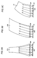
Fig. 9A is a front view of reflector emission units according to a third exemplary embodiment of the present invention; -
Fig. 9B is a front view of reflector emission units according to a fourth exemplary embodiment of the present invention; -
Fig. 9C is a front view of reflector emission units according to a fifth exemplary embodiment of the present invention; and -
Fig. 10 is a perspective view showing the reflector emission unit according to a sixth exemplary embodiment of the present invention. - Next, a first exemplary embodiment of the invention will be described. In
Figs. 1 through 3 , alamp housing 1 includes alamp body 11 which can be mounted on a right-hand side of a rear part of a vehicle body and which has a vessel-like shape which is made to open in a front surface (a front side) thereof. Thelamp housing 1 also includes a transparentfront cover 12 which is attached to the front opening. Thefront cover 12 has a curved shape which projects to the front or in a left-right direction so as to follow the rounded shape of the vehicle body so as to configure part of the vehicle body shape of the vehicle. The lamp of the first exemplary embodiment is configured as a multi-function lamp having a tail lamp function and a stop lamp function. Accordingly, integrally incorporated within thelamp housing 1 are a light guide plate emission unit 2 (a first light emitting unit) which is made into a tail lamp which is lit while the vehicle is driven during night time and a reflector emission unit 3 (a second light emitting unit) which is made into a stop lamp which is lit when the brakes are applied. In addition, although the illustration and description of a left-hand lamp are omitted here, since the left-hand lamp is transversely symmetrical with the right-hand lamp, in the following description, "right" is to be read as "left" for description of the left-hand lamp. -
Fig. 4 is a partial exploded perspective view of part of the lamp of the first exemplary embodiment which illustrates schematic configurations of the light guideplate emission unit 2 and thereflector emission unit 3. The light guideplate emission unit 2 comprises a plate-likelight guide plate 21 and an LED element assembly. Thelight guide plate 21 has a width dimension that is gradually reduced as thelight guide plate 21 extends from a left lower area to a right upper area within thelamp housing 1 as viewed from the front of the lamp (i.e., from the rear of the vehicle) and which is curved so as to warp gradually to the rear as viewed in a thickness direction. The LED element assembly 22 (a first light source) includes a plurality of LED elements which are arranged on a lower side of a lower end face of thelight guide plate 21 so as to confront the lower end face of thelight guide plate 21. In addition, in the same figure, thereflector emission unit 3 includes amain reflector 31 which is disposed behind the light guideplate emission unit 2 and is made to extend over an area almost equal to the whole surface of thefront cover 12 and a stem-shapedcenter portion 32 which is provided to stretch horizontally in a position lying on a front side of themain reflector 31. Although not shown inFig. 4 , but as will be described later, thecenter portion 32 includes inside thereof an LED element assembly (a second light source) comprising a plurality ofLED elements 332 which are arranged in a length direction of thecenter portion 32 and a sub-reflector 34 which is arranged so as to be opposed to the LED element assembly 33 (see, e.g.,Fig. 7 ). -
Fig. 5 is an enlarged perspective view of part of the light guideplate emission unit 2 andFigs. 6A and 6B are a front view and a side view, respectively, which show a conceptual configuration of the light emittinglight guide plate 2.
Thelight guide plate 21 is such that a transparent material which transmits light is worked into a substantially uniform thickness and is formed into the curved shape which is moderately curved to the right while the width dimension thereof is gradually reduced as thelight guide plate 21 extends from the left lower area to the right upper area when viewed from the front. Moreover, when viewed in the thickness direction, thelight guide plate 21 is formed in a curved shape which warps towards the rear of the lamp with a moderate curvature along a curved inner surface of the front cover. A front surface of thelight guide plate 21 is made into a light emission surface 21o which emits light, and the light emission surface 21o is made into a shape which is curved in a third-dimensional direction due to the curved construction of thelight guide plate 21 described above.
A large number ofminute reflecting elements 211 are provided on a back side of thelight guide plate 21 for reflecting light that is guided through thelight guide plate 21. Theminute reflecting elements 211 comprise conical or pyramidal minute recesses, that is, so-called stipples, which are arranged over almost the whole area of the back side of thelight guide plate 21. In addition, an end face of the left lower area of thelight guide plate 21 is configured as alight introduction surface 21i. Anelongated steppedplate 23 which is made of a material which transmits light is disposed near thelight introduction surface 21i, and a plurality ofLED elements 222 are arranged along the stepped plate on a lower side of the steppedplate 23, so as to confront thelight introduction surface 21i via the steppedplate 23. In this exemplary embodiment, theLED elements 222 are red. TheLED elements 222 are mounted in a row at intervals on anelongated circuit board 221. Further, theLED elements 222 are supported on a supportingbase plate 223 and are then formed into theLED element assembly 22. Although theLED elements 222 may be provided either in the form of a chip or as discrete LED elements, an optical axis Ox of light emitted from eachLED element 222 is oriented in a vertical direction. Namely, the light output axis of theLED elements 222 is oriented vertically relative to thelight introduction surface 21i. - The stepped
plate 23 is formed of a transparent resin into an elongated plate piece-like shape and is supported integrally on the supportingbase plate 223 of theLED element assembly 22 at both longitudinal ends thereof. A lower surface of the steppedplate 23 is made intooptical steps 231 for refracting light from theindividual LED elements 222 such that the input direction of the light is changed when the light is inputted to thelight introduction surface 21i. Here, theoptical steps 231 are formed so as to be divided so as to correspond individually to therespective LED elements 222 and are made up of wedge-shaped steps of which input surfaces are inclined at different angles relative to the optical axes Ox of light which is outputted from theindividual LED elements 222. In addition, in the first exemplary embodiment, in order to reduce the thickness of the steppedplate 23, eachoptical step 231 is formed as a Fresnel lens. Accordingly, a plurality of wedge-shapedsteps 231 a are provided for eachLED element 222. For example, in this exemplary embodiment, there are three wedge-shapedsteps 231a for every oneLED element 222. By this configuration, the steppedplate 23 is formed into a serrated configuration in which a plurality of wedge-shapedsteps 231a which are inclined identically or differently are arranged. - Namely, in each
optical step 231, the light introduction surface is oriented at an angle at which light emitted from the corresponding LED element is, as will be described later, oriented in the three-dimensionally curved direction of the light guide plate when the light is refracted by theoptical step 231, for example, at an angle at which light is oriented, as is shown inFig. 6A , towards the right upper area of thelight guide plate 21 when viewed from the front. Here, thestep plate 23 is formed into the serrated configuration in which respective inclination angles of theoptical steps 231 are increased in a stepped fashion from the right to the left so that a refraction angle, at which light emitted from an LED element lying further leftwards when viewed from the front is refracted to the right, is larger than a refraction angle at which light emitted from the LED element which lies further rightwards is refracted to the light. Note thatFig. 6A is a conceptual diagram showing a configuration in which a singleoptical step 231 is aligned with eachLED element 222 which is so drawn for the sake of easy description of the refraction angles. In reality, however, as is shown inFig. 5 , eachoptical step 231 is made up of the Fresnel lens having a plurality of wedge-shapedsteps 231a for each one of theLED elements 22. - In addition, the
light guide plate 21 is curved in the thickness direction, and a sectional shape in the thickness direction of eachoptical step 231 has, as is shown inFig. 6B , a lean-to sectional shape in which the light introduction surface is inclined towards the front side so that light emitted from eachLED element 22 is directed upwards towards the rear along the curvature of thelight guide plate 21 in the thickness direction. Here, the inclination angles of the light introduction surfaces which are oriented to the front are almost the same for each of theoptical steps 231. - In the light guide
plate emission unit 2, although light emitted from theindividual LED elements 222 is directed vertically upwards so as to be inputted to the steppedplate 23, light inputted to the respective optical steps of the steppedplate 23 is refracted by the individualoptical steps 231 so as to be inputted into the interior of thelight guide plate 21 from thelight introduction surface 21i of thelight guide plate 21, the light so inputted being then guided upwards in the interior of thelight guide plate 21. Since theoptical steps 231 are formed into the serrated configuration when viewed from the front and into the lean-to configuration when viewed from the side, as has been described above, the light refracted by theoptical steps 231 is directed upwards towards the right as is shown inFig. 6A when viewed from the front and is directed upwards towards the rear as is shown inFig. 6B when viewed from the side. Then, the light guided into the interior of thelight guide plate 21 is guided as far as a right upper area while being internally reflected on front, rear, left-hand and right-hand surfaces of thelight guide plate 21. The light guided in this way is reflected on the minutelight reflecting elements 211 in the course of guiding, whereby part of the light so reflected is reflected towards the front of thelight guide plate 21 so as to be outputted to the front of the lamp from the light emission surface 21o at the front of thelight guide plate 21. - As this occurs, since the light being guided in the interior of the
light guide plate 21 is absorbed by thelight guide plate 21 or part of the light being so guided leaks out from the front, rear, left-hand and right-hand surfaces of thelight guide plate 21 as the light is guided towards the right upper area, the quantity of light that is guided as far as the right upper area would normally be reduced. However, in the first exemplary embodiment, since the light inputted from thelight introduction surface 21i is directed towards the direction which matches the three-dimensionally curved direction of the light emission surface 21o of thelight guide plate 21, the angle of incidence of light or at which light is inputted into thelight guide plate 21 for internal reflection on the internal surfaces such as the curved front and rear surfaces, as well as both the left-hand and right-hand surfaces can be made larger than a critical angle, thereby making it possible to suppress the leakage of light to the outside of thelight guide plate 21.
In addition, since the width dimension of thelight guide plate 21 is made to be reduced gradually towards the right upper area, even though the quantity of light is reduced, the quantity of light per unit area of thelight guide plate 21 in the right upper area (i.e., the brightness in the right upper area) is maintained at such a level that there is generated no remarkable difference in brightness between the right upper area and the left lower area of thelight guide plate 21. Further, thelight guide plate 21 may be formed in such a manner that the thickness thereof is reduced as the distance from thelight introduction surface 21i increases. As this occurs, the quantity of light emitted from the light emission surface 21o becomes more difficult to be attenuated even in positions which lie far apart from theLED elements 222, thereby making it possible to obtain a uniform surface illumination. Consequently, light can be outputted with uniform brightness over the whole surface area of the light guide plate, whereby thelight guide plate 21 is made to function as an illuminant uniformly bright over the whole surfaces thereof.
Incidentally, inFigs. 6A, 6B , in the event that light emitted from theindividual LED elements 222 is inputted to thelight introduction surface 21i in the optical axis direction Ox, since the angle of incidence or the angle at which light is so inputted for projection on the curved left-hand inner surface of thelight guide plate 21 is large, the quantity of light which is not totally reflected is increased, whereby the quantity of light which is guided as far as the right upper area is decreased remarkably, and therefore, it becomes more difficult to illuminate brightly the right upper area. -
Fig. 7 is a partial exploded perspective view showing a schematic configuration of thereflector emission unit 3. Referring toFigs. 2 and3 , as well, themain reflector 31 is formed in such a manner that firstly, a front surface of thelamp body 11 is formed so that a vertical section has a reflecting surface configuration and thereafter, a surface treatment such as plating or depositing of metal such as aluminum is applied to the front surface. Thismain reflector 31 comprises a plurality ofunit reflecting surfaces 311 which are arranged in such a manner that a horizontal section of themain reflector 31 has a staircase-like configuration which matches the horizontally curved configuration of thefront cover 12. - Further, referring to
Fig.10 , the eachunit reflecting surface 311 is divided horizontally into three areas which individually configure minutewidth reflecting surfaces 311a. A front surface (i.e., a reflecting surface) of each minutewidth reflecting surface 311a is made up of reflectingsteps 311b which each have a substantially projecting spherical configuration and which are arranged in the vertical direction. Since the respective reflectingsteps 311b of the minutewidth reflecting surfaces 311a which adjoin each other are arranged so as to be aligned in position with each other with respect to the vertical direction, when themain reflector 31 is seen from the front, theindividual reflecting steps 311b are arranged in a grid-like array. By this, although the individualunit reflecting surfaces 311 are made into reflecting surfaces which reflect light projected thereon into a pencil of light which is substantially parallel with respect to the vertical direction, at the same time, the individualunit reflecting surfaces 311 are made into reflecting surfaces which reflect light projected thereon while being diffused vertically and horizontally by theindividual reflecting steps 311b. In addition, as to the orientations of the plurality ofunit reflecting surfaces 311, although theunit reflecting surfaces 311 which are disposed on a side of the lamp which lies closer to the center of the vehicle on which the lamp is mounted are oriented to the forward direction, theunit reflecting surfaces 311 which are disposed on a side of the lamp which lies closer to the outside of the vehicle (in this exemplary embodiment, a right-hand side of the lamp) are set in such a manner that theunit reflecting surfaces 311 which are disposed further rightwards are oriented further rightwards. In particular, in the case of thefront cover 12 being extended to turn toward the side area of the vehicle, theunit reflecting surfaces 311 of themain reflector 31 are formed to be extended to the area to which thefront cover 12 turns round. - Returning to
Fig. 7 , anextension 312 forming a dummy reflector is provided so as to extend integrally around the periphery of themain reflector 31. The lower end portion of thelight guide plate 21, theLED element assembly 22 and the steppedplate 23 of the light guideplate emission unit 2 are disposed underneath theextension 312 through aslit 313 provided in a lower area of theextension 312. Since these members are concealed by theextension 312, they are made to be prevented from being exposed to the outside through thefront cover 12. In addition, theslit 313 is also prevented from being exposed to the outside by a decorative plate 24 (refer toFig. 2 ). Note that the left-hand lamp has an opposite configuration to what has been described heretofore. - The
center portion 32 is made to extend long in the horizontal left-right direction along a line which connects together horizontally positions which lie in the vicinity of focal point positions of the respectiveunit reflecting surfaces 311 of the main reflector 31 (focal points in a parabolic surface which configures a vertical section of each unit reflecting surface). In addition, a section of thecenter portion 32 which follows a direction along the lamp optical axis Lx is formed into a configuration in which thecenter portion 32 is opened in a V shape on a back side thereof towards the back of the lamp, and thecenter portion 32 is fixed to left-hand and right-hand walls of theextension 312 at both end portions thereof in the direction in which thecenter portion 32 extends. To fix thecenter portion 32 in this way, a locking construction which is not illustrated in the drawings or a fixing construction which employs screws or the like is employed. Thecenter portion 32 is thus aligned relative to themain reflector 31, that is, thecenter portion 32 is located in the position which lies substantially close to the focal point positions of the unit reflecting surfaces 311.
Afront surface 321 of thecenter portion 32 has a sectional configuration which is slightly recessed in the vertical direction, and as with themain reflector 31, a surface treatment for reflecting light is applied to thefront surface 321. On the other hand, a horizontally elongatedcircuit board 331 is disposed on a back side in the V-shaped interior of thecenter portion 32 so as to project in a staircase-like fashion in which a plurality offlat portions 331a are connected together via correspondingstep portions 331b at equal intervals to the intervals at which the respectiveunit reflecting surfaces 311 of themain reflector 31 are arranged horizontally and, moreover, so as to be spaced an equal distance apart from front surfaces of the individual unit reflecting surfaces 311. Thecircuit board 331 is integrally supported on thecenter portion 32. Here, thecircuit board 331 is fixedly supported on thecenter portion 32 in a plurality of locations in the length direction by way of bonding or with screws. A singlelight emitting LED 332 is mounted on each of the plurality of individualflat portions 331a of thecircuit board 331 with its light output direction oriented in the direction towards the back side. TheLEDs 332 configure an LED assembly 33 (a second light source). TheseLED elements 332 may be provided either in the form of a chip or as discrete LED elements, and the number ofLED elements 332 is larger than that ofLEDs 222 of the light guideplate emission unit 2, whereby theLED assembly 33 is configured as a light source which is illuminated with high luminous intensity as a whole. However, alternatively, a plurality ofLED elements 222 may be mounted on each of the plurality offlat portions 331a. - A sub-reflector 34 is provided so as to extend horizontally along the
center portion 32 in a position which lies on a back side of theLED assembly 33 and where light emitted from theindividual LED elements 332 is projected, and is supported on thecircuit board 331 in a plurality of locations in a length direction thereof with screws or the like. The sub-reflector 34 is bent in a staircase-like fashion so as to ensure an equal space between theindividual LED elements 332 and the sub-reflector 34 to thereby be formed to have a stem-like configuration having a horizontal narrow width.Auxiliary reflecting surfaces 341 are formed in positions which are opposed to theindividual LED elements 332 in the optical axis direction. Theauxiliary reflecting surfaces 341 each have a horizontally collapsed V-shaped section for reflecting light emitted from theLED elements 332, and respective front surfaces thereof are surface treated so as to be made into light reflecting surfaces. Theseauxiliary reflecting surfaces 341 are made to reflect light emitted from theindividual LED elements 332, with respect to the vertical direction, at a relatively large angle so that light so outputted is made to be projected onto the upper and lower areas of themain reflector 31 which resides backwards thereof. That is, theauxiliary reflecting surfaces 341 reflect light towards the individualunit reflecting surfaces 311 of themain reflector 31 excluding areas lying in the vicinity of the lamp optical axis Lx, in other words, so as to be diffused so that the width of the pencil of light is extended.
Since theauxiliary reflecting surfaces 341 are each formed to have a curved surface which is inclined in the directions towards the respective vertical upper and lower back sides and which is made to project slightly, light emitted from theindividual LED elements 332 is reflected while being diffused in the vertical directions. As this occurs, since light emitted from theLED elements 332 is originally reflected while being diffused slightly, even though theauxiliary reflecting surfaces 341 are formed into flat planes, light reflected by theauxiliary reflecting surfaces 341 can be made into diffused light. In addition, the sub-reflector 34 may be supported directly on thecenter portion 32. By adopting this configuration, not only thecircuit board 331 and theLED elements 332 which are mounted thereon but also the sub-reflector 34 in this exemplary embodiment are covered to be concealed by thecenter portion 32 so as not to be exposed to or seen from the outside when thecircuit board 331, theLED elements 332, and the sub-reflector 34 are attempted to be viewed from the front of the lamp. - Horizontal and vertical light paths of the
reflector emission unit 3 are shown inFigs. 8A, 8B , respectively. Light emitted towards the back side of the lamp from theindividual LED elements 332 is reflected on the individualauxiliary reflecting surfaces 341 of the sub-reflector 34. However, as this occurs, since the front surfaces of the sub-reflector 34 are inclined upwards and downwards, light is reflected so as to spread in the vertical directions at a relatively large angle. On the other hand, as to the horizontal direction, light is reflected in the direction towards where the light was outputted.
Light reflected by the sub-reflector 34 is projected on themain reflector 31, where light is reflected in the forward direction, so as to be outputted to the front of the tail lamp, that is, to the rear of the motor vehicle through thefront cover 12. As this occurs, light emitted from theindividual LED elements 332 and reflected on the sub-reflector 34 is projected on to the correspondingunit reflecting surfaces 311 of therespective LED elements 332 on themain reflector 31 so as to be reflected on the individual unit reflecting surfaces 311. As this occurs, light reflected on the individualunit reflecting surfaces 311 forms a pencil of light which is nearly parallel and is directed generally towards the front of the lamp because the vertical sections of the minutewidth reflecting surfaces 311a which make up theunit reflecting surfaces 311 each have the parabolic surface configuration. As this occurs, since the minutewidth reflecting surfaces 311a are each formed of the large number of reflectingsteps 311b, the pencil of light formed is diffused slightly in the horizontal direction and the vertical direction. As this occurs, with respect particularly to the vertical direction, since light emitted form theLED elements 332 is projected onto the areas on themain reflector 31 which exclude the areas lying in the vicinity of the lamp optical axis Lx of themain reflector 31, all the light so projected is reflected on theunit reflecting surfaces 311 so as to be outputted in the direction towards the front of the lamp. Because of this, there is no such situation that light from theLED elements 332 is projected onto the areas of themain reflector 31 which lie in the vicinity of the lamp optical axis Lx, and light reflected there is interrupted by the sub-reflector 34 or thecenter portion 32, whereby the light is not outputted in the direction towards the front of the lamp, the light utilization efficiency being thereby reduced. When viewed from the front of the lamp, an illuminated state is generated in the lamp in which the area resulting from the combination of themain reflector 31 and thecenter portion 32 is illuminated. - Since the
unit reflecting surfaces 311 each have the parabolic vertical section, most of light reflected by the individualunit reflecting surfaces 311 is made to configure a pencil of nearly parallel light which is directed in the direction towards the front of the lamp. With respect to the horizontal direction, since theunit reflecting surfaces 311 each have the linear horizontal section, light emitted from theLED elements 332 is reflected as it keeps the form of a pencil of light which was the form in which it was outputted from theLED elements 332 and remains in the same form even after the reflection. As this reflection takes place, since the minutewidth reflecting surfaces 311a are each made up of the large number of reflectingsteps 311b which each have the projecting surface configuration, light is diffused while being reflected. As a result, there is produced an illuminating form in which the singleunit reflecting surface 311 of themain reflector 31 is illuminated by thesingle LED element 332, and moreover, an illumination can be realized which is uniform over the whole surface of themain reflector 31 except for shaded portions which are produced in the vicinity of the lamp optical axis Lx of the main reflector. - In addition, in this way, by reflecting light emitted from the
LED elements 332 in such a state that the light is divided vertically by the sub-reflector 34 and making the light so reflected be projected onto themain reflector 31, the light can be projected over the wide area on themain reflector 31 even though the space dimension between theLED elements 332 and themain reflector 31 is small. Because of this, the dimension of thereflector emission unit 3 which follows the lamp optical axis Lx can be reduced, which becomes advantageous in realizing a reduction in thickness of the tail lamp. In particular, even in the tail lamp in which the light guideplate emission unit 2 is incorporated, which was described in first exemplary embodiment, the dimension along the lamp optical axis direction can be reduced, thereby making it possible to reduce the thickness of the lamp. - Further, since the
circuit board 331 is made to extend horizontally in the left-right direction by the plurality offlat portions 331a on which theLED elements 332 are mounted being connected together via thecorresponding step portions 331b, theLED elements 332 can be mounted on the individualflat portions 331a with their optical axis directions oriented towards the lamp optical axis Lx. In addition, by thestep portions 331b being designed as require, the plurality ofLED elements 332 can be positioned on the three-dimensional plane along the horizontal curved configuration of themain reflector 31, that is, along the focal point positions of the individual unit reflecting surfaces 311. Because of this, in each of theLED elements 332, an illumination is enabled which extends widely over the horizontal length range of thecircuit board 331 while maintaining the vertical light distribution characteristics and has the uniform brightness. Thus, thereflector emission unit 3 can be applied particularly to the lamp of which the light emitting surface has a three-dimensional plane which matches the body shape of the motor vehicle. - On the other hand, in each
unit reflecting surface 311, there exists an area where light from eachLED element 332 is not projected in the area which is opposed to by the sub-reflector 34 which includes an illumination optical axis Ox of theLED element 332. No reflected light from themain reflector 31 exists in this area, and hence, when the tail lamp is seen from the front, that portion configures a shaded portion. However, since this area is an area which does not originally contribute to the illumination of the lamp, this becomes advantageous in enhancing the utilization efficiency of light.
Further, part of light which is reflected at both the vertical end portions, that is, the upper area and the lower area of eachunit reflecting surface 311, is reflected largely downwards or upwards by virtue of the diffused reflection at the reflectingsteps 311b, and the light so reflected is then projected onto thefront surface 321 of thecenter portion 32. Since thefront surface 321 of the center portion is formed into a reflecting surface having a recessed or concave surface configuration, the light is reflected on thefront surface 321 so as to be directed towards the front of the lamp. Consequently, when the lamp is seen from the front, the reflected light reflected on the individualunit reflecting surfaces 311 and the reflected light reflected on thefront surface 321 of thecenter portion 32 are made integral with each other so as to be outputted to the front of the lamp through thefront cover 12. When seen from the front of the lamp, there is produced an illuminated state that is generated in the lamp in which the area resulting from the combination of themain reflector 31 and thecenter portion 32 is illuminated. By this, the dark area which resides in the vicinity of the optical axis of themain reflector 31 and where the reflected light reflected at the sub-reflector 34 is not projected is illuminated by the reflected light reflected at thecenter portion 32, whereby the risk of producing a dark portion is eliminated. Consequently, an illumination with uniform brightness can be realized which extends over the large light emitting area by utilizing the whole surface of themain reflector 31 as the light emitting surface, which is uniform in brightness over the whole surface of themain reflector 31, and which is free from a dark area due to the reflection from thecenter portion 32 being able to be used to eliminate the dark area which would otherwise be produced. - In the lamp of the first exemplary embodiment which includes the light guide
plate emission unit 2 and thereflector emission unit 3, when the vehicle is driven during night time, theLED elements 222 which function as the first light source are illuminated. Light emitted from theLED elements 222 is refracted on theoptical steps 231 on the steppedplate 23 and is inputted into thelight guide plate 21 from thelight introduction surface 21i which is the lower end face of thelight guide plate 21 and is thereafter guided in the interior thereof. In addition, the light so guided is outputted from the light emission surface 21o of thelight guide plate 21 at theminute reflecting elements 211. As this occurs, since light refracted by theoptical steps 231 and guided in the interior of thelight guide plate 21 is directed in the direction which matches the three-dimensionally curved configuration of the light emission surface 21o of thelight guide plate 21 as has been described before, the internal reflection within thelight guide plate 21 is promoted so as to reduce the leakage of light from both the lateral surfaces and the back surface of thelight guide plate 21. This enhances the light guiding efficiency within thelight guide plate 21, and the light output efficiency from the light emission surface 21o at the bent right upper area of the light guide plate is also enhanced.
In addition, since the light emission surface 21o of thelight guide plate 21 is given the configuration in which the width dimension is gradually reduced towards the right upper area, the surface area of the right upper area becomes smaller than that of the left lower area, whereby even though light attenuation is generated in guiding light in the interior of thelight guide plate 21, the light output efficiency per unit area can be made almost the same, and hence, light is outputted with almost the same brightness over the whole surfaces of thelight guide plate 21. In addition, light that is not reflected by theminute reflecting elements 211 in thelight guide plate 21 and light that is not reflected on the inner surfaces of thelight guide plate 21 are outputted from not only the front and back surface but also the left-hand and right-hand lateral surfaces so as to configure light that is diffused horizontally and vertically from thelight guide plate 21 within the lamp, whereby when the lamp is seen from the left-hand or right-hand side or top or bottom side thereof, thelight guide plate 21 is seen as being illuminated. This produces a form in which thelight guide plate 21 is illuminated over the whole surfaces with almost uniform brightness, whereby the lamp is lit in the illumination form which is superior with respect to design. - On the other hand, when the brakes of the vehicle are applied, the
LED elements 332 which function as the second light source are illuminated. Light emitted from theindividual LED elements 332 is diffused vertically at a large angle on theauxiliary reflecting surfaces 341 of the sub-reflector 34 and is reflected horizontally in the direction towards where the light was originally outputted. By this reflection, light from theindividual LED elements 332 is projected on to the minutewidth reflecting surfaces 331 and is then reflected individually. Most of the light is reflected in the direction towards the front of the lamp and is then outputted in the direction towards the front of the lamp through thefront cover 12. As this occurs, in the area where thelight guide plate 21 is superimposed when the lamp is seen from the front, light from thereflector 31 passes through thelight guide plate 21 in the thickness direction and is thereafter outputted from thefront cover 12. In addition, light reflected on the upper area and the lower area of themain reflector 31 is directed towards the center portion and is then reflected on thefront surface 321 of thecenter portion 32. Then, the light so reflected is directed towards the front of the lamp and is then outputted through thefront cover 12. By this, since light emitted from themain reflector 31 and light emitted from thecenter portion 32 are combined together so as to be outputted from thefront cover 12, when the lamp is seen from the front, a state is produced in which these areas are illuminated brightly as a whole, whereby thereflector emission unit 3 is lit as the stop lamp which is illuminated with higher luminous intensity than the light guideplate emission unit 2. - Moreover, in the lamp of first exemplary embodiment, when the lamp is lit to function as the tail lamp, the lamp is lit in such a state that the
light guide plate 21 is illuminated over the whole surfaces thereof, while when the lamp is lit to function as the stop lamp, the lamp is lit in such a state that themain reflector 31 and thecenter portion 32 are illuminated. By this configuration, the illumination patterns of the lamp when lit are changed between the tail lamp and stop lamp functions, and a following vehicle is allowed to easily identify the illuminations for the tail lamp function and the stop lamp function through the different illumination patterns. In addition to this, since the illumination is implemented by thelight guide plate 21 when the lamp is lit to function as the tail lamp, the lamp is lit in such a way as to output soft light, and therefore, there is no such situation that the following vehicle is dazzled. Since the illumination is implemented by themain reflector 31 which employs as the light source the large number of LED elements 322 when the lamp is lit to function as the stop lamp, the lamp is lit in such a way as to output light with high luminous intensity, and hence, an ensured indication that the brakes are being applied can be given to the following vehicle. - Additionally, in the first exemplary embodiment, the sectional shape of the
center portion 32 is made in a V-shape opening in the lateral direction and thefront surface 321 is made as a recessed surface. Thus, the light reflected on thefront surface 321 is projected along with the lamp optical axis Lx. However, when reflecting the light on thefront surface 321, an uneven pattern (i.e., a linear brilliant or a dark pattern) may be generated at an apex of thefront surface 321. In this case, if the sectional shape of thecenter portion 32 is made as a curved shape such as semi-circular shape or semi-ellipse shape, the diffusion direction of the reflecting light at the front side of thecenter portion 32 becomes substantially uniform in a wide range, and thus, such the uneven pattern is not generated.
Further, thecenter portion 32 is not necessarily disposed in a central position relative to the vertical direction of themain reflector 31. Even if thecenter portion 32 is disposed at a position shifted from the center, if the lamp has a configuration that the light emitted from theLED element 332 is reflected on the sub-reflector 34 to be projected toward themain reflector 31 and the light is reflected and projected toward the front side of the lamp by themain reflector 31, the present invention can be applied thereto. - In addition, although illustration is omitted, the configuration of the reflection steps 311b of the minute
width reflecting surfaces 311a of the main reflector is not limited to the projecting spherical surface which is realized in the first exemplary embodiment, and hence, a semi-cylindrical reflection step may be adopted whose vertical section has a convex or projecting configuration. - While in the first exemplary embodiment, the light emission surface of the light guide plate is illustrated as having a configuration in which the light emission surface is curved curvilinearly from the bottom left area to the top right and rearward area when the tail lamp is seen from the front, the invention can be applied equally in the event that the configuration of the optical steps is changed to match a different front surface configuration of the light guide plate. For example, a
light guide plate 21A according to a second exemplary embodiment shown inFig. 9A has a configuration in which thelight guide plate 21 is nearly symmetrical in a horizontal direction and is curved in a three-dimensional direction in such a manner that the width dimension of thelight guide plate 21 is gradually reduced from a lower portion towards an upper portion. In the case of thelight guide plate 21A, an optical step at a central portion of a steppedplate 23A has a configuration in which no light is refracted in such a way that light from an LED element is directed vertically upwards, whereas optical steps lying left wards and rightwards thereof are given configurations in which light from correspondingLED elements 222 are refracted in such a way as to be gradually inclined towards the center of thelight guide plate 21A. - Alternately, in a third exemplary embodiment shown in
Fig. 9B , alight guide plate 21B is formed as having a configuration in which thelight guide plate 21B is curved in a three-dimensional direction in such a way as to extend obliquely with a substantially equal width dimension. In the case of thelight guide plate 21B, individual optical steps on a stepped plate 23B may be formed to have the same configuration so that light is refracted in the same direction. In the case of the third exemplary embodiment, since the optical steps do not have to be formed to have the serrated configuration, the stepped plate 32B is configured as a simple tapered plate. - While in the first, second, and third exemplary embodiments, the optical steps are made into the stepped plate and are configured as a separate member from the light guide plate, as is illustrated by the fourth exemplary embodiment shown in
Fig. 9(c) , it also possible to formoptical steps 231 integrally on a light introduction surface of alight guide plate 21. By adopting this configuration, the necessity of a stepped plate is obviated, which is advantageous in reducing the number of constituent components. Alternately, a stepped plate which is formed separately from alight guide plate 21 as in the first, second, and third exemplary embodiments may be joined or bonded integrally to a light introduction surface of the light guide plate, which is advantageous in simplifying the configuration. - The light guide plate of the light guide plate emission unit of the invention is not limited to those having the configurations illustrated in the first, second, third, and fourth exemplary embodiments. The invention may be applied equally to a light emitting unit including a light guide plate whose side edges are shaped in such a way as to be bent curvilinearly or rectilinearly therealong or which is bent curvilinearly in its thickness direction and in which light from the light source unit is inputted into the interior of the light guide plate from one end face thereof so as to be guided therethrough. Further, although illustration is omitted, in the case of the light guide plate being curved three-dimensionally, also in a case where a configuration is adopted in which a light guide plate is curved so as to be twisted in its thickness direction to match the three-dimensional curvature of a front cover, a configuration may only have to be adopted for optical steps which correspond to individual LED elements in which the light refracting direction at the optical steps matches the curvilinear configuration of the light guide plate.
- According to one or more illustrative aspects of the invention, there is provided a lamp including:
- a light guide plate emission unit including:
- a first light source;
- a light guide plate including:
- a light introduction surface provided so as to oppose to the first light source; and
- a curved light emission surface through which the light introduced from the light introduction surface and passing through the light guide plate is emitted; and
- an optical step which is provided on the light introduction surface and which refracts the introduced light to a direction in which the light emission surface is curved.
- According to the illustrative aspects, since light emitted from the LEDs is diffused and reflected by the sub-reflector and is then reflected by the main reflector so as to be emitted towards the front of the lamp, the substantial reflecting surface of the main reflector can be increased, thereby making it possible to provide the lamp having the wide light emitting area. In addition, since the base plate on which the LEDs are mounted extends by connecting the plurality of flat portions together with the step portions, the light emitting area can be extended in the direction in which the base plate extends, and the light emitting surface can be formed into the three-dimensional plane, whereby the lamp can be applied to a lamp in which a light emitting surface is curved. Further, the design portion covers the base plate and the LEDs so as not to be exposed from the front of the lamp, and also since the design portion covers the areas which do not constitute the reflecting surface of the main reflector, the aesthetic external appearance of the lamp is improved.
- Moreover, the sub-reflector may be adapted to reflect light emitted from the LEDs in a direction vertical to the extending direction of the design portion while diffusing the light widely, and the main reflector may include a plurality of unit reflecting surfaces which are disposed stepwisely so as to follow a curved configuration of a front cover of the lamp housing. In this case, a light distribution area in a direction perpendicular to the extending direction of the design portion (which is the same as the extending direction of the base plate or the arrangement direction of the LEDs) is enlarged. Further, even if the lamp extends to reach a side portion of the lamp (such as the front cover greatly curving in the horizontal direction), the reflecting surface of the main reflector can be provided on the thus curved area and the lamp can emit the light uniformly including the thus curved area.
- Further, the design portion may include a reflecting surface at a front side thereof, and the main reflector may include reflecting steps for reflecting part of the reflected light towards the reflecting surface of the design portion. Since part of the light reflected by the main reflector is reflected on the front surface of the design portion, a lamp can be obtained in which both the main reflector and the design portion function as the light emitting surface, and hence, no dark portion is generated and the light can be emitted over a wide area.
- Furthermore, according to illustrative aspects of the invention, the base plate may be adapted to be supported on the design portion, the sub-reflector may be supported on either the base plate or the design portion, the design portion may include a fixed portion at an end of the extending direction and the fixed portion of the design portion may be supported on a fixing portion of the lamp so as to be positioned relative the main reflector.
The fixing portion of the lamp is not limited to the main reflector, as long as the design portion is fixedly supported relative to the main reflector, the fixing portion may be the lamp body or the dummy reflector (such as an extension) which is formed integrally with the main reflector.
Since the base plate and the sub-reflector are supported directly or indirectly on the design portion and the design portion is supported in such a state that the design portion is positioned relative to the main reflector, the LEDs mounted on the base plate and the sub-reflector are positioned relative to the main reflector, whereby the lamp can be obtained which has the light distribution pattern as designed. - According to one or more additional illustrative aspects of the invention, there is provided a lamp including:
- a lamp housing;
- a plurality of LEDs provided within the lamp housing;
- a main reflector disposed so as to oppose to the LEDs for reflecting light emitted from the individual LEDs towards a front side of the lamp;
- a sub-reflector interposed between the LEDs and the main reflector for reflecting light emitted from the LEDs towards the main reflector while diffusing the light;
- a base plate extending along with the LEDs and having a plurality of flat portions;
- a design portion which covering the base plate and the LEDs so as not to be exposed to the front side of the lamp,
- Here, the curved shape of the light emitting surface denotes a shape in which the light emitting surface is not a flat shape but a curved shape with respect to at least one of horizontal and vertical directions.
- According to the additional illustrative aspects of the invention, when the light emitted from the first light source is introduced from the light introduction surface, the light is refracted by the optical step toward the curved direction of the light emission surface. Since thus refracted light is guided through the light guide plate, the leakage of the light from the light guide plate can be suppressed and the light can be efficiently guided to an area located far from the light introduction surface. Thus, a uniform light emission over the whole surface area of the light emission surface is enabled. Accordingly, the light emission surface with uniform brightness is obtained and the lamp having improved illumination effect and external appearance is obtained.
- Additionally, the width dimension of the light emission surface of the light guide plate may be gradually decreases with distance from the light introduction surface. Accordingly, even in the event that the intensity of light is attenuated as it is guided in the interior of the light guide plate, the brightness of the light emission surface per unit area can be made equal.
Further, the first light source may be a plurality of LED elements which are arranged along the light introduction surface, the optical step may be a plurality of light refraction members, and a number of the light refraction members may be the same as a number of the LED elements. Here, the optical step may be identical or different shape each other. Further, the optical step may be separated from or integrated with the light guide plate. In this case, even if the first light source has the plurality of LED elements, light from the respective LED elements can be guided towards the curved direction of the light emission surface, whereby the light guiding efficiency or light emission efficiency can be enhanced so as to obtain a bright light emitting surface. - Furthermore, the lamp may further include a lamp housing including: a lamp body; and a curved front cover attached to a front side of the lamp body, the first light emission unit being mounted within the lamp housing, and the light emission surface of the light guide plate being curved so as to follow the front cover. Even if the light emission surface of the light guide plate is designed so as to be curved along the front cover of the lamp, the light emission surface of the light guide plate can be illuminated with uniform brightness, whereby the illumination effect and external appearance of the lamp are improved.
- Further, the lamp may further include a second light emission unit mounted within the lamp housing, the second light emission unit including: a second light source; and a reflector which is arranged so as to extend along a certain area so as to oppose to the front cover and is adapted to reflect light emitted from the second light source toward a front side of the lamp, wherein the light guide plate is arranged so as to partially overlap the reflector in a position on a front side of the reflector when viewed from the front of the lamp.
By selectively lighting the reflector emission unit and the light guide plate emission unit, the one lamp can be lit in different light emitting forms, whereby the one lamp can be used for lamps having different functions, and the design of the lamp can be enhanced.
While the present invention has been shown and described with reference to certain exemplary embodiments thereof, it will be understood by those skilled in the art that various changes in form and details may be made therein without departing from the spirit and scope of the invention as defined by the appended claims.
The features of all dependent claims can be combined with each other, as long as they do not contradict each other.
wherein at least one of the LEDs are mounted on the flat portion, and
wherein the design portion extends in a direction in which the base plate extends.
Claims (12)
- A lamp comprising:a lamp housing;a plurality of light emitting diodes (LEDs) provided within the lamp housing;a main reflector disposed so as to oppose to the LEDs for reflecting light emitted from the LEDs towards a front side of the lamp;a sub-reflector which is interposed between the LEDs and the main reflector, and which reflects and diffuses the light emitted from the LEDs towards the main reflector;an LED element assembly which extends in parallel with the sub-reflector and comprises a plurality of flat portions, each flat portion corresponding to one of the plurality of LEDs and on which the corresponding LED is mounted, adjacent ones of the flat portions being coupled together by at least one step portion; anda center portion which covers the LED element assembly and the LEDs such that the LEDs are not exposed to the front side of the lamp.
- The lamp as set forth in Claim 1,
wherein the sub-reflector reflects and diffuses the light emitted from the LEDs in a direction vertical to the extending direction of the center portion,
wherein the lamp housing comprises a front cover, and
wherein the main reflector comprises a plurality of unit reflecting surfaces which are disposed stepwisely so as to follow a contour of a front cover of the lamp housing. - The lamp as set forth in Claim 1,
wherein the center portion comprises a reflecting surface on a front side thereof, and
wherein the main reflector comprises a plurality of reflecting steps which are arranged in an array and reflect part of the light towards the front of the lamp. - The lamp as set forth in Claim 1,
wherein the LED element assembly is supported on the center portion,
wherein the sub-reflector is supported on either the LED element assembly or the center portion,
wherein the center portion comprises a fixed portion at an end of the center portion in the extending direction, and
wherein the fixed portion is supported on a fixing portion of the lamp so as to be positioned relative to the main reflector. - A lamp comprising:a first light emission unit comprising:a first light source;a light guide plate comprising:a light introduction surface provided so as to oppose to the first light source; anda curved light emission surface which emits light from the first light source that has passed through the light introduction surface; andan optical step which is provided on the light introduction surface and which refracts the light from the first light source in a direction in which the light emission surface is curved.
- The lamp as set forth in Claim 5,
wherein width dimension of the curved light emission surface of the light guide plate gradually decreases with distance from the light introduction surface. - The lamp as set forth in Claim 5,
wherein the first light source comprises a plurality of light emitting diode (LED) elements which are arranged parallel to the light introduction surface,
wherein the optical step comprises a plurality of light refraction members. - The lamp as set forth in Claim 7,
wherein a number of the light refraction members is the same as a number of the LED elements. - The lamp as set forth in Claim 5, further comprising:a lamp housing comprising:wherein the light guide plate is mounted within the lamp housing, anda lamp body; anda curved front cover attached to a front side of the lamp body,
wherein the curved light emission surface of the light guide plate is curved so as to follow the front cover. - The lamp as set forth in Claim 9, further comprising:a second light emission unit which is mounted within the lamp housing, and comprises:wherein the light guide plate is arranged so as to partially overlap the reflector in a position on a front side of the reflector when viewed from the front of the lamp.a second light source; anda reflector which is arranged so as to oppose to the front cover and is adapted to reflect light emitted from the second light source toward a front side of the lamp, and
- The lamp as set forth in Claim 5, further comprising:a second light emission unit which is mounted within the lamp housing, the second light emission unit comprising:a plurality of light emitting diodes (LEDs) provided within the lamp housing;a main reflector disposed so as to oppose to the LEDs for reflecting light emitted from the LEDs towards a front side of the lamp;a sub-reflector which is interposed between the LEDs and the main reflector, and which reflects and diffuses the light emitted from the LEDs towards the main reflector;an LED element assembly which extends in parallel with the sub-reflector and comprises a plurality of flat portions, each flat portion corresponding to one of the plurality of LEDs and on which the corresponding LED is mounted, adjacent ones of the flat portions being coupled together by at least one step portion;a center portion which covers the LED element assembly and the LEDs such that the LEDs are not exposed to the front side of the lamp,wherein the first light emission unit is positioned between the second light emission unit and a front cover of the lamp housing.
- A lamp comprising:a lamp housing;a reflector emission unit comprising:an light emitting diode (LED) assembly comprising a plurality of reflective surfaces and a plurality of first LEDs, each of the reflective surfaces having one of the first LEDS mounted thereon, and adjacent ones of the reflective surfaces connected together by a reflective step portion;a main reflector comprising a plurality of unit reflecting surfaces which are arranged in a grid-like array and reflect light from the first LEDs toward a front of the lamp housing, and an extension that extends around a periphery of the plurality of unit reflecting surfaces and comprises a slit therein;a sub-reflector which is provided between the LED assembly and the main reflector, and which comprises a plurality of auxiliary reflecting surfaces which reflect and diffuse light emitted from the first LEDs toward the main reflector; anda center portion which is provided between the LED assembly and the front of the lamp housing so as to cover the LED assembly; anda light guide plate emission unit comprising:a plurality of second LEDs;a light guide plate comprising:a light introduction surface provided so as to face the plurality of second LEDs; anda curved light emission surface, the curved light emission surface which emits light, from the second LEDs that has passed through the light introduction surface, toward the front of the lamp housing; anda stepped plate comprising a plurality of optical steps which is provided on the light introduction surface and which refract the light from the second LEDs in a direction in which the curved light emission surface is curved,wherein a portion of the curved light emission surface extends through the slit in the extension of the main reflector.
Applications Claiming Priority (2)
| Application Number | Priority Date | Filing Date | Title |
|---|---|---|---|
| JP2008179997A JP5210062B2 (en) | 2008-07-10 | 2008-07-10 | Lamp |
| JP2008179996A JP5210061B2 (en) | 2008-07-10 | 2008-07-10 | Lamp |
Publications (3)
| Publication Number | Publication Date |
|---|---|
| EP2143991A2 true EP2143991A2 (en) | 2010-01-13 |
| EP2143991A3 EP2143991A3 (en) | 2010-11-10 |
| EP2143991B1 EP2143991B1 (en) | 2012-05-02 |
Family
ID=41151953
Family Applications (1)
| Application Number | Title | Priority Date | Filing Date |
|---|---|---|---|
| EP09008985A Not-in-force EP2143991B1 (en) | 2008-07-10 | 2009-07-09 | Lamp |
Country Status (4)
| Country | Link |
|---|---|
| US (1) | US8292480B2 (en) |
| EP (1) | EP2143991B1 (en) |
| KR (1) | KR101061409B1 (en) |
| AT (1) | ATE556271T1 (en) |
Cited By (19)
| Publication number | Priority date | Publication date | Assignee | Title |
|---|---|---|---|---|
| DE102010026043A1 (en) * | 2010-07-03 | 2012-01-05 | Volkswagen Ag | Lamp for two-piece rear light module of vehicle, has housing comprising bar for fastening lens, where bar defines region that is not observed by lens from outside, and light emitting unit is arranged within region |
| ITTV20100138A1 (en) * | 2010-10-19 | 2012-04-20 | Automotive Lighting Rear Lamps Ital Ia S P A | AUTOMOTIVE HEADLIGHT |
| EP2503222A1 (en) * | 2011-03-15 | 2012-09-26 | Odelo GmbH | Motor vehicle light and method for its operation |
| EP2574836A1 (en) * | 2011-09-29 | 2013-04-03 | Odelo GmbH | Motor vehicle light |
| EP2527722A3 (en) * | 2011-05-27 | 2013-12-04 | Automotive Lighting Reutlingen GmbH | Lighting device for a motor vehicle |
| WO2015043819A1 (en) * | 2013-09-19 | 2015-04-02 | Hella Kgaa Hueck & Co. | Lighting device for vehicles |
| EP2386794A3 (en) * | 2010-05-12 | 2015-11-11 | Ichikoh Industries, Ltd. | Vehicle lighting device |
| US9734365B2 (en) | 2012-09-10 | 2017-08-15 | Avery Dennison Retail Information Services, Llc | Method for preventing unauthorized diversion of NFC tags |
| US9767329B2 (en) | 2012-11-19 | 2017-09-19 | Avery Dennison Retail Information Services, Llc | NFC tags with proximity detection |
| WO2017174342A1 (en) * | 2016-04-06 | 2017-10-12 | Bayerische Motoren Werke Aktiengesellschaft | Lighting device for a vehicle |
| EP2581647A3 (en) * | 2011-10-14 | 2017-12-13 | Koito Manufacturing Co., Ltd. | Vehicular lamp |
| US9858583B2 (en) | 2011-09-01 | 2018-01-02 | Avery Dennison Retail Information Services, Llc | Apparatus, system and method for tracking consumer product interest using mobile devices |
| US9892398B2 (en) | 2011-11-02 | 2018-02-13 | Avery Dennison Retail Information Services, Llc | Distributed point of sale, electronic article surveillance, and product information system, apparatus and method |
| CN108508688A (en) * | 2018-03-12 | 2018-09-07 | 广东欧珀移动通信有限公司 | Laser emitter, project structured light module, depth camera and electronic equipment |
| US10540527B2 (en) | 2012-10-18 | 2020-01-21 | Avery Dennison Retail Information Services Llc | Method, system and apparatus for NFC security |
| EP3472936B1 (en) | 2016-06-21 | 2020-07-08 | Dr. Schneider Kunststoffwerke GmbH | Device having at least one region that can be illuminated |
| US10977969B2 (en) | 2010-01-29 | 2021-04-13 | Avery Dennison Retail Information Services, Llc | RFID/NFC panel and/or array used in smart signage applications and method of using |
| US10977965B2 (en) | 2010-01-29 | 2021-04-13 | Avery Dennison Retail Information Services, Llc | Smart sign box using electronic interactions |
| US11091091B2 (en) | 2016-04-06 | 2021-08-17 | Bayerische Motoren Werke Aktiengesekkschaft | Lighting device for a vehicle |
Families Citing this family (63)
| Publication number | Priority date | Publication date | Assignee | Title |
|---|---|---|---|---|
| US20120162985A1 (en) * | 2009-04-24 | 2012-06-28 | Sunovia Energy Technologies, Inc. | Solid state lighting unit incorporating optical spreading elements |
| WO2010129355A2 (en) * | 2009-04-28 | 2010-11-11 | Sunovia Energy Technologies, Inc. | Solid state luminaire with reduced optical losses |
| DE102010013931A1 (en) * | 2010-04-06 | 2011-10-06 | Automotive Lighting Reutlingen Gmbh | Modular light guide device for motor vehicle lighting devices |
| JP5538089B2 (en) | 2010-06-23 | 2014-07-02 | スタンレー電気株式会社 | Vehicle lamp unit |
| JP5575592B2 (en) * | 2010-09-17 | 2014-08-20 | 株式会社小糸製作所 | Vehicle lighting |
| JP5657358B2 (en) * | 2010-12-02 | 2015-01-21 | スタンレー電気株式会社 | Vehicle lighting |
| US9103953B2 (en) * | 2011-01-03 | 2015-08-11 | Lunera Lighting Inc. | Off-axis illumination LED luminaire |
| JP5869223B2 (en) * | 2011-02-09 | 2016-02-24 | 株式会社小糸製作所 | Vehicle headlamp |
| DE102011050062A1 (en) * | 2011-05-03 | 2012-11-08 | Hella Kgaa Hueck & Co. | Lighting device for vehicles, has light conductor provided with two narrow sides, which connect longitudinal sides, where distance between longitudinal sides specifies thickness of light conductor |
| CZ306862B6 (en) | 2011-06-23 | 2017-08-16 | Varroc Lighting Systems, s.r.o. | A headlight signal lamp with a hidden light source |
| JP5779045B2 (en) * | 2011-08-25 | 2015-09-16 | スタンレー電気株式会社 | Vehicle lighting |
| US10132470B2 (en) * | 2011-09-05 | 2018-11-20 | Robe Lighting S.R.O. | Versatile beam and wash optical system for an automated luminaire |
| US8702288B2 (en) * | 2011-12-06 | 2014-04-22 | Ford Global Technologies, Llc | Optical element for a vehicle lighting assembly |
| JP5937836B2 (en) * | 2012-02-07 | 2016-06-22 | 株式会社小糸製作所 | Vehicle lighting |
| US9194566B2 (en) * | 2012-06-08 | 2015-11-24 | Lg Innotek Co., Ltd. | Lamp unit and vehicle lamp apparatus using the same |
| JP6166104B2 (en) * | 2012-06-08 | 2017-07-19 | エルジー イノテック カンパニー リミテッド | Lamp unit and vehicle using the same |
| US8714793B2 (en) * | 2012-07-10 | 2014-05-06 | Osram Sylvania Inc. | LED headlight with one or more stepped upward-facing reflectors |
| KR102080610B1 (en) | 2012-11-14 | 2020-02-25 | 엘지이노텍 주식회사 | Lamp and vehicle lamp apparatus for using the same |
| WO2014105408A2 (en) | 2012-12-28 | 2014-07-03 | 3M Innovative Properties Company | Hybrid tailight article |
| EP2941367B1 (en) * | 2013-01-07 | 2020-12-16 | SMR Patents S.à.r.l. | An external rear view mirror of a vehicle |
| US9869432B2 (en) | 2013-01-30 | 2018-01-16 | Cree, Inc. | Luminaires using waveguide bodies and optical elements |
| US9581751B2 (en) | 2013-01-30 | 2017-02-28 | Cree, Inc. | Optical waveguide and lamp including same |
| US9366396B2 (en) | 2013-01-30 | 2016-06-14 | Cree, Inc. | Optical waveguide and lamp including same |
| US9625638B2 (en) | 2013-03-15 | 2017-04-18 | Cree, Inc. | Optical waveguide body |
| US9442243B2 (en) | 2013-01-30 | 2016-09-13 | Cree, Inc. | Waveguide bodies including redirection features and methods of producing same |
| US9291320B2 (en) | 2013-01-30 | 2016-03-22 | Cree, Inc. | Consolidated troffer |
| US9798072B2 (en) | 2013-03-15 | 2017-10-24 | Cree, Inc. | Optical element and method of forming an optical element |
| US9709725B2 (en) * | 2013-03-15 | 2017-07-18 | Cree, Inc. | Luminaire utilizing waveguide |
| US10502899B2 (en) * | 2013-03-15 | 2019-12-10 | Ideal Industries Lighting Llc | Outdoor and/or enclosed structure LED luminaire |
| US9366799B2 (en) | 2013-03-15 | 2016-06-14 | Cree, Inc. | Optical waveguide bodies and luminaires utilizing same |
| US10209429B2 (en) | 2013-03-15 | 2019-02-19 | Cree, Inc. | Luminaire with selectable luminous intensity pattern |
| US10379278B2 (en) * | 2013-03-15 | 2019-08-13 | Ideal Industries Lighting Llc | Outdoor and/or enclosed structure LED luminaire outdoor and/or enclosed structure LED luminaire having outward illumination |
| USD749759S1 (en) * | 2013-09-02 | 2016-02-16 | Jaguar Land Rover Limited | Vehicle component |
| KR102217466B1 (en) | 2013-12-02 | 2021-02-22 | 엘지이노텍 주식회사 | Lmap unit and lighting device and vehicle lamp using the same |
| US9651740B2 (en) | 2014-01-09 | 2017-05-16 | Cree, Inc. | Extraction film for optical waveguide and method of producing same |
| DE102014200474A1 (en) * | 2014-01-14 | 2015-07-30 | Volkswagen Aktiengesellschaft | Lighting device for a motor vehicle |
| DE102014104756A1 (en) * | 2014-04-03 | 2015-10-08 | Hella Kgaa Hueck & Co. | Lighting device for vehicles |
| USD736451S1 (en) * | 2014-07-31 | 2015-08-11 | GM Global Technology Operations LLC | Vehicle front headlamp lens |
| US10100995B2 (en) * | 2014-09-30 | 2018-10-16 | Maxell, Ltd. | Vehicular lighting apparatus |
| JP6511244B2 (en) * | 2014-10-10 | 2019-05-15 | 株式会社小糸製作所 | Lighting light guide |
| USD760146S1 (en) | 2014-12-23 | 2016-06-28 | Dean Andrew Wilkinson | Aircraft light unit |
| KR102501102B1 (en) * | 2015-06-12 | 2023-02-20 | 삼성디스플레이 주식회사 | Curved display device and fabrication method of the same |
| US10197245B1 (en) | 2015-11-09 | 2019-02-05 | Abl Ip Holding Llc | Asymmetric vision enhancement optics, luminaires providing asymmetric light distributions and associated methods |
| US10030837B2 (en) * | 2016-01-28 | 2018-07-24 | Honda Motor Co., Ltd. | Lighting system |
| US11719882B2 (en) | 2016-05-06 | 2023-08-08 | Ideal Industries Lighting Llc | Waveguide-based light sources with dynamic beam shaping |
| US10416377B2 (en) | 2016-05-06 | 2019-09-17 | Cree, Inc. | Luminaire with controllable light emission |
| JP6357507B2 (en) * | 2016-07-04 | 2018-07-11 | 日本精機株式会社 | Vehicle display device |
| USD805224S1 (en) * | 2016-08-12 | 2017-12-12 | Bombardier Recreational Products Inc. | Pair of off-road vehicle headlamps |
| WO2018038015A1 (en) * | 2016-08-26 | 2018-03-01 | 株式会社小糸製作所 | Vehicle lighting fixture |
| KR101863787B1 (en) * | 2016-09-20 | 2018-06-01 | 에스엘 주식회사 | Lamp for vehicle |
| CZ2018147A3 (en) | 2018-03-23 | 2019-10-02 | Varroc Lighting Systems, s.r.o. | Lighting equipment for motor vehicles |
| US10739513B2 (en) | 2018-08-31 | 2020-08-11 | RAB Lighting Inc. | Apparatuses and methods for efficiently directing light toward and away from a mounting surface |
| CN108895405A (en) * | 2018-09-06 | 2018-11-27 | 马瑞利汽车零部件(芜湖)有限公司 | Light curtain vehicle signal lamp optical system |
| US10801679B2 (en) | 2018-10-08 | 2020-10-13 | RAB Lighting Inc. | Apparatuses and methods for assembling luminaires |
| JP2020077564A (en) * | 2018-11-09 | 2020-05-21 | 株式会社小糸製作所 | Vehicle lamp fitting |
| US11002420B2 (en) | 2018-12-21 | 2021-05-11 | Magna Exteriors Inc. | Vehicle headlamp having light guide |
| GB2585687B (en) | 2019-07-11 | 2021-08-18 | Dyson Technology Ltd | Vehicle lamps |
| EP3772610B1 (en) | 2019-08-06 | 2022-04-20 | Nichia Corporation | Lighting device |
| DE102020102555A1 (en) * | 2020-02-03 | 2021-08-05 | HELLA GmbH & Co. KGaA | Lighting device for vehicles |
| KR20230022943A (en) | 2020-06-03 | 2023-02-16 | 제이드 버드 디스플레이(상하이) 리미티드 | Systems and Methods for Multicolor LED Pixel Unit with Horizontal Light Emission |
| WO2021247887A1 (en) * | 2020-06-03 | 2021-12-09 | Jade Bird Display (shanghai) Limited | Systems and methods for multi-color led pixel unit with vertical light emission |
| DE102022105628A1 (en) * | 2022-03-10 | 2023-09-14 | HELLA GmbH & Co. KGaA | Lighting device for vehicles and injection molding machine |
| TWI802455B (en) * | 2022-06-28 | 2023-05-11 | 敏翔股份有限公司 | Vehicle lamp structure |
Citations (3)
| Publication number | Priority date | Publication date | Assignee | Title |
|---|---|---|---|---|
| JP2000251508A (en) | 1999-02-25 | 2000-09-14 | Stanley Electric Co Ltd | Lamp for vehicle |
| JP2001297609A (en) | 2000-04-14 | 2001-10-26 | Stanley Electric Co Ltd | Signal lamp for car |
| JP2003059313A (en) | 2001-08-15 | 2003-02-28 | Koito Mfg Co Ltd | Vehicule lighting device |
Family Cites Families (23)
| Publication number | Priority date | Publication date | Assignee | Title |
|---|---|---|---|---|
| US4949226A (en) * | 1988-06-24 | 1990-08-14 | Koito Seisakusko Co., Ltd. | Projector-type lighting device of expanded outline appearance for use as a vehicular headlamp or the like |
| US5278731A (en) | 1992-09-10 | 1994-01-11 | General Electric Company | Fiber optic lighting system using conventional headlamp structures |
| DE4417695C2 (en) * | 1994-05-20 | 1998-01-29 | Reitter & Schefenacker Gmbh | Motor vehicle light |
| DE50015035D1 (en) | 1999-01-21 | 2008-04-24 | Fer Fahrzeugelektrik Gmbh | vehicle light |
| DE20013330U1 (en) | 2000-08-02 | 2001-01-11 | Fer Fahrzeugelektrik Gmbh | Motor vehicle light |
| DE10101795A1 (en) | 2001-01-17 | 2002-07-18 | Bosch Gmbh Robert | Flashing light, especially front flashing light, for motor vehicles has boundary light source in part of light conducting element in part of path of light from flashing light source |
| DE20102587U1 (en) | 2001-02-14 | 2001-05-10 | Fer Fahrzeugelektrik Gmbh | Vehicle light |
| JP4030728B2 (en) * | 2001-04-25 | 2008-01-09 | 株式会社小糸製作所 | Vehicle headlamp |
| DE10153543A1 (en) | 2001-10-30 | 2003-05-15 | Hella Kg Hueck & Co | Illumination device for vehicles has light conductor with wall region for deflecting incident light to deflection points formed by transverse hole also transverse to main light radiation direction. |
| JP4094366B2 (en) * | 2002-07-24 | 2008-06-04 | 株式会社小糸製作所 | Vehicle lighting |
| JP4118647B2 (en) * | 2002-10-24 | 2008-07-16 | 株式会社小糸製作所 | Vehicle sign light |
| FR2849157B1 (en) * | 2002-12-20 | 2015-07-10 | Valeo Vision | DEVICE FOR LIGHTING AND / OR SIGNALING THE PROJECTOR OR FIRE TYPE FOR A MOTOR VEHICLE |
| US7036967B2 (en) * | 2002-12-24 | 2006-05-02 | Ichikoh Industries, Ltd. | Vehicle lamp |
| US6976769B2 (en) * | 2003-06-11 | 2005-12-20 | Cool Options, Inc. | Light-emitting diode reflector assembly having a heat pipe |
| DE10329185A1 (en) | 2003-06-27 | 2005-01-20 | Guido Kellermann Produktentwicklung & Handel | Light for a vehicle |
| US7029150B2 (en) | 2004-01-23 | 2006-04-18 | Guide Corporation | Catadioptric light distribution system |
| JP4339143B2 (en) | 2004-02-10 | 2009-10-07 | 株式会社小糸製作所 | Vehicle lamp unit |
| US7249877B2 (en) * | 2004-09-23 | 2007-07-31 | Osram Sylvania Inc. | Led lamp bulb assembly and reflector system |
| JP2006236588A (en) | 2005-02-22 | 2006-09-07 | Koito Mfg Co Ltd | Optical llumination device and vehicular lighting fixture |
| JP2006302713A (en) | 2005-04-21 | 2006-11-02 | Koito Mfg Co Ltd | Vehicle head-lamp |
| US7438454B2 (en) | 2005-11-29 | 2008-10-21 | Visteon Global Technologies, Inc. | Light assembly for automotive lighting applications |
| FR2898660B1 (en) | 2006-03-16 | 2008-06-13 | Automotive Lighting Rear Lamps | MOTOR VEHICLE SIGNALING LIGHT WITH UNIFORM EXTERIOR APPEARANCE. |
| JP2010503960A (en) | 2006-09-15 | 2010-02-04 | コーニンクレッカ フィリップス エレクトロニクス エヌ ヴィ | Flat, thin, LED-based light emitter that provides collimated light |
-
2009
- 2009-07-01 US US12/496,086 patent/US8292480B2/en not_active Expired - Fee Related
- 2009-07-09 EP EP09008985A patent/EP2143991B1/en not_active Not-in-force
- 2009-07-09 AT AT09008985T patent/ATE556271T1/en active
- 2009-07-10 KR KR1020090063175A patent/KR101061409B1/en not_active IP Right Cessation
Patent Citations (3)
| Publication number | Priority date | Publication date | Assignee | Title |
|---|---|---|---|---|
| JP2000251508A (en) | 1999-02-25 | 2000-09-14 | Stanley Electric Co Ltd | Lamp for vehicle |
| JP2001297609A (en) | 2000-04-14 | 2001-10-26 | Stanley Electric Co Ltd | Signal lamp for car |
| JP2003059313A (en) | 2001-08-15 | 2003-02-28 | Koito Mfg Co Ltd | Vehicule lighting device |
Cited By (29)
| Publication number | Priority date | Publication date | Assignee | Title |
|---|---|---|---|---|
| US10977969B2 (en) | 2010-01-29 | 2021-04-13 | Avery Dennison Retail Information Services, Llc | RFID/NFC panel and/or array used in smart signage applications and method of using |
| US10977965B2 (en) | 2010-01-29 | 2021-04-13 | Avery Dennison Retail Information Services, Llc | Smart sign box using electronic interactions |
| EP2386794A3 (en) * | 2010-05-12 | 2015-11-11 | Ichikoh Industries, Ltd. | Vehicle lighting device |
| DE102010026043A1 (en) * | 2010-07-03 | 2012-01-05 | Volkswagen Ag | Lamp for two-piece rear light module of vehicle, has housing comprising bar for fastening lens, where bar defines region that is not observed by lens from outside, and light emitting unit is arranged within region |
| ITTV20100138A1 (en) * | 2010-10-19 | 2012-04-20 | Automotive Lighting Rear Lamps Ital Ia S P A | AUTOMOTIVE HEADLIGHT |
| WO2012052946A1 (en) * | 2010-10-19 | 2012-04-26 | Automotive Lighting Italia S.P.A. | Automotive light |
| EP2503222A1 (en) * | 2011-03-15 | 2012-09-26 | Odelo GmbH | Motor vehicle light and method for its operation |
| EP2527722A3 (en) * | 2011-05-27 | 2013-12-04 | Automotive Lighting Reutlingen GmbH | Lighting device for a motor vehicle |
| US10607238B2 (en) | 2011-09-01 | 2020-03-31 | Avery Dennison Corporation | Apparatus, system and method for consumer tracking consumer product interest using mobile devices |
| US9858583B2 (en) | 2011-09-01 | 2018-01-02 | Avery Dennison Retail Information Services, Llc | Apparatus, system and method for tracking consumer product interest using mobile devices |
| EP2574836A1 (en) * | 2011-09-29 | 2013-04-03 | Odelo GmbH | Motor vehicle light |
| EP2581647A3 (en) * | 2011-10-14 | 2017-12-13 | Koito Manufacturing Co., Ltd. | Vehicular lamp |
| US9892398B2 (en) | 2011-11-02 | 2018-02-13 | Avery Dennison Retail Information Services, Llc | Distributed point of sale, electronic article surveillance, and product information system, apparatus and method |
| US9734365B2 (en) | 2012-09-10 | 2017-08-15 | Avery Dennison Retail Information Services, Llc | Method for preventing unauthorized diversion of NFC tags |
| US10282572B2 (en) | 2012-09-10 | 2019-05-07 | Avery Dennison Retail Information Services, Llc | Method for preventing unauthorized diversion of NFC tags |
| US11126803B2 (en) | 2012-10-18 | 2021-09-21 | Avery Dennison Corporation | Method, system and apparatus for NFC security |
| US10540527B2 (en) | 2012-10-18 | 2020-01-21 | Avery Dennison Retail Information Services Llc | Method, system and apparatus for NFC security |
| US10970496B2 (en) | 2012-11-19 | 2021-04-06 | Avery Dennison Retail Information Services, Llc | NFC tags with proximity detection |
| US10402598B2 (en) | 2012-11-19 | 2019-09-03 | Avery Dennison Retail Information Services, Llc | NFC tags with proximity detection |
| US9767329B2 (en) | 2012-11-19 | 2017-09-19 | Avery Dennison Retail Information Services, Llc | NFC tags with proximity detection |
| US10113706B2 (en) | 2013-09-19 | 2018-10-30 | HELLA GmbH & Co. KGaA | Laser lighting device |
| WO2015043819A1 (en) * | 2013-09-19 | 2015-04-02 | Hella Kgaa Hueck & Co. | Lighting device for vehicles |
| DE102013110344B4 (en) | 2013-09-19 | 2022-09-01 | HELLA GmbH & Co. KGaA | Lighting device for vehicles for generating tail light and rear fog light functions |
| WO2017174342A1 (en) * | 2016-04-06 | 2017-10-12 | Bayerische Motoren Werke Aktiengesellschaft | Lighting device for a vehicle |
| US11084421B2 (en) | 2016-04-06 | 2021-08-10 | Bayerische Motoren Werke Aktiengesellschaft | Lighting device for a vehicle |
| US11091091B2 (en) | 2016-04-06 | 2021-08-17 | Bayerische Motoren Werke Aktiengesekkschaft | Lighting device for a vehicle |
| EP3472936B1 (en) | 2016-06-21 | 2020-07-08 | Dr. Schneider Kunststoffwerke GmbH | Device having at least one region that can be illuminated |
| CN108508688A (en) * | 2018-03-12 | 2018-09-07 | 广东欧珀移动通信有限公司 | Laser emitter, project structured light module, depth camera and electronic equipment |
| CN108508688B (en) * | 2018-03-12 | 2021-10-19 | Oppo广东移动通信有限公司 | Laser emitter, structured light projection module, depth camera and electronic equipment |
Also Published As
| Publication number | Publication date |
|---|---|
| ATE556271T1 (en) | 2012-05-15 |
| US8292480B2 (en) | 2012-10-23 |
| KR101061409B1 (en) | 2011-09-01 |
| EP2143991B1 (en) | 2012-05-02 |
| US20100008088A1 (en) | 2010-01-14 |
| EP2143991A3 (en) | 2010-11-10 |
| KR20100007801A (en) | 2010-01-22 |
Similar Documents
| Publication | Publication Date | Title |
|---|---|---|
| EP2143991B1 (en) | Lamp | |
| JP5210061B2 (en) | Lamp | |
| US6805476B2 (en) | Led-type vehicular lamp having uniform brightness | |
| JP4290601B2 (en) | Vehicle lamp unit and vehicle lamp | |
| KR101114183B1 (en) | Lighting assembly | |
| US8870423B2 (en) | Vehicle decorative lighting device and vehicle lamp | |
| JP4937649B2 (en) | Vehicle lighting | |
| US8480266B2 (en) | Vehicle light unit and vehicle light | |
| JP5553643B2 (en) | Vehicle lighting | |
| JP2004055482A (en) | Lighting fixture for vehicle | |
| US20030043593A1 (en) | Led-type vehicular lamp | |
| JP2004235153A (en) | Light guide equipped with reflecting plate | |
| US10816159B2 (en) | Vehicle lamp | |
| JP6855404B2 (en) | Vehicle lighting | |
| JP7278920B2 (en) | Light guide lens, lens assembly and vehicle lamp | |
| US9862306B2 (en) | Vehicle decorative lighting device and vehicle lamp | |
| JP5210062B2 (en) | Lamp | |
| JP2008103273A (en) | Vehicular lighting fixture | |
| JP6383583B2 (en) | Vehicle lighting device | |
| JP6221438B2 (en) | Vehicle lighting | |
| EP1363067A2 (en) | Vehicle lamp with visor | |
| JP7205193B2 (en) | vehicle lamp | |
| JP2019050132A (en) | Vehicular lighting fixture | |
| JP2010211945A (en) | Optical module and signal lamp for vehicle | |
| JP7205194B2 (en) | vehicle lamp |
Legal Events
| Date | Code | Title | Description |
|---|---|---|---|
| PUAI | Public reference made under article 153(3) epc to a published international application that has entered the european phase |
Free format text: ORIGINAL CODE: 0009012 |
|
| 17P | Request for examination filed |
Effective date: 20090709 |
|
| AK | Designated contracting states |
Kind code of ref document: A2 Designated state(s): AT BE BG CH CY CZ DE DK EE ES FI FR GB GR HR HU IE IS IT LI LT LU LV MC MK MT NL NO PL PT RO SE SI SK SM TR |
|
| PUAL | Search report despatched |
Free format text: ORIGINAL CODE: 0009013 |
|
| AK | Designated contracting states |
Kind code of ref document: A3 Designated state(s): AT BE BG CH CY CZ DE DK EE ES FI FR GB GR HR HU IE IS IT LI LT LU LV MC MK MT NL NO PL PT RO SE SI SK SM TR |
|
| AX | Request for extension of the european patent |
Extension state: AL BA RS |
|
| RIC1 | Information provided on ipc code assigned before grant |
Ipc: F21V 7/00 20060101ALI20110526BHEP Ipc: F21Y 101/02 20060101ALN20110526BHEP Ipc: F21W 101/14 20060101ALN20110526BHEP Ipc: F21S 8/10 20060101AFI20110526BHEP |
|
| GRAP | Despatch of communication of intention to grant a patent |
Free format text: ORIGINAL CODE: EPIDOSNIGR1 |
|
| RIN1 | Information on inventor provided before grant (corrected) |
Inventor name: MOCHIZUKI, MIKIC/O KOITO MANUFACTURING CO., LTD. Inventor name: KOIZUMI, HIROYAC/O KOITO MANUFACTURING CO., LTD. |
|
| GRAS | Grant fee paid |
Free format text: ORIGINAL CODE: EPIDOSNIGR3 |
|
| GRAA | (expected) grant |
Free format text: ORIGINAL CODE: 0009210 |
|
| AK | Designated contracting states |
Kind code of ref document: B1 Designated state(s): AT BE BG CH CY CZ DE DK EE ES FI FR GB GR HR HU IE IS IT LI LT LU LV MC MK MT NL NO PL PT RO SE SI SK SM TR |
|
| REG | Reference to a national code |
Ref country code: GB Ref legal event code: FG4D |
|
| RIN1 | Information on inventor provided before grant (corrected) |
Inventor name: KOIZUMI, HIROYAC/O KOITO MANUFACTURING CO., LTD. Inventor name: MOCHIZUKI, MIKIC/O KOITO MANUFACTURING CO., LTD. |
|
| REG | Reference to a national code |
Ref country code: AT Ref legal event code: REF Ref document number: 556271 Country of ref document: AT Kind code of ref document: T Effective date: 20120515 Ref country code: CH Ref legal event code: EP |
|
| REG | Reference to a national code |
Ref country code: IE Ref legal event code: FG4D |
|
| REG | Reference to a national code |
Ref country code: DE Ref legal event code: R096 Ref document number: 602009006678 Country of ref document: DE Effective date: 20120621 |
|
| REG | Reference to a national code |
Ref country code: NL Ref legal event code: VDEP Effective date: 20120502 |
|
| REG | Reference to a national code |
Ref country code: LT Ref legal event code: MG4D Effective date: 20120502 |
|
| PG25 | Lapsed in a contracting state [announced via postgrant information from national office to epo] |
Ref country code: LT Free format text: LAPSE BECAUSE OF FAILURE TO SUBMIT A TRANSLATION OF THE DESCRIPTION OR TO PAY THE FEE WITHIN THE PRESCRIBED TIME-LIMIT Effective date: 20120502 Ref country code: SE Free format text: LAPSE BECAUSE OF FAILURE TO SUBMIT A TRANSLATION OF THE DESCRIPTION OR TO PAY THE FEE WITHIN THE PRESCRIBED TIME-LIMIT Effective date: 20120502 Ref country code: CY Free format text: LAPSE BECAUSE OF FAILURE TO SUBMIT A TRANSLATION OF THE DESCRIPTION OR TO PAY THE FEE WITHIN THE PRESCRIBED TIME-LIMIT Effective date: 20120502 Ref country code: FI Free format text: LAPSE BECAUSE OF FAILURE TO SUBMIT A TRANSLATION OF THE DESCRIPTION OR TO PAY THE FEE WITHIN THE PRESCRIBED TIME-LIMIT Effective date: 20120502 Ref country code: NO Free format text: LAPSE BECAUSE OF FAILURE TO SUBMIT A TRANSLATION OF THE DESCRIPTION OR TO PAY THE FEE WITHIN THE PRESCRIBED TIME-LIMIT Effective date: 20120802 Ref country code: IS Free format text: LAPSE BECAUSE OF FAILURE TO SUBMIT A TRANSLATION OF THE DESCRIPTION OR TO PAY THE FEE WITHIN THE PRESCRIBED TIME-LIMIT Effective date: 20120902 Ref country code: PL Free format text: LAPSE BECAUSE OF FAILURE TO SUBMIT A TRANSLATION OF THE DESCRIPTION OR TO PAY THE FEE WITHIN THE PRESCRIBED TIME-LIMIT Effective date: 20120502 |
|
| REG | Reference to a national code |
Ref country code: AT Ref legal event code: MK05 Ref document number: 556271 Country of ref document: AT Kind code of ref document: T Effective date: 20120502 |
|
| PG25 | Lapsed in a contracting state [announced via postgrant information from national office to epo] |
Ref country code: HR Free format text: LAPSE BECAUSE OF FAILURE TO SUBMIT A TRANSLATION OF THE DESCRIPTION OR TO PAY THE FEE WITHIN THE PRESCRIBED TIME-LIMIT Effective date: 20120502 Ref country code: SI Free format text: LAPSE BECAUSE OF FAILURE TO SUBMIT A TRANSLATION OF THE DESCRIPTION OR TO PAY THE FEE WITHIN THE PRESCRIBED TIME-LIMIT Effective date: 20120502 Ref country code: LV Free format text: LAPSE BECAUSE OF FAILURE TO SUBMIT A TRANSLATION OF THE DESCRIPTION OR TO PAY THE FEE WITHIN THE PRESCRIBED TIME-LIMIT Effective date: 20120502 Ref country code: PT Free format text: LAPSE BECAUSE OF FAILURE TO SUBMIT A TRANSLATION OF THE DESCRIPTION OR TO PAY THE FEE WITHIN THE PRESCRIBED TIME-LIMIT Effective date: 20120903 Ref country code: GR Free format text: LAPSE BECAUSE OF FAILURE TO SUBMIT A TRANSLATION OF THE DESCRIPTION OR TO PAY THE FEE WITHIN THE PRESCRIBED TIME-LIMIT Effective date: 20120803 |
|
| PG25 | Lapsed in a contracting state [announced via postgrant information from national office to epo] |
Ref country code: BE Free format text: LAPSE BECAUSE OF FAILURE TO SUBMIT A TRANSLATION OF THE DESCRIPTION OR TO PAY THE FEE WITHIN THE PRESCRIBED TIME-LIMIT Effective date: 20120502 |
|
| PG25 | Lapsed in a contracting state [announced via postgrant information from national office to epo] |
Ref country code: NL Free format text: LAPSE BECAUSE OF FAILURE TO SUBMIT A TRANSLATION OF THE DESCRIPTION OR TO PAY THE FEE WITHIN THE PRESCRIBED TIME-LIMIT Effective date: 20120502 Ref country code: RO Free format text: LAPSE BECAUSE OF FAILURE TO SUBMIT A TRANSLATION OF THE DESCRIPTION OR TO PAY THE FEE WITHIN THE PRESCRIBED TIME-LIMIT Effective date: 20120502 Ref country code: DK Free format text: LAPSE BECAUSE OF FAILURE TO SUBMIT A TRANSLATION OF THE DESCRIPTION OR TO PAY THE FEE WITHIN THE PRESCRIBED TIME-LIMIT Effective date: 20120502 Ref country code: CZ Free format text: LAPSE BECAUSE OF FAILURE TO SUBMIT A TRANSLATION OF THE DESCRIPTION OR TO PAY THE FEE WITHIN THE PRESCRIBED TIME-LIMIT Effective date: 20120502 Ref country code: AT Free format text: LAPSE BECAUSE OF FAILURE TO SUBMIT A TRANSLATION OF THE DESCRIPTION OR TO PAY THE FEE WITHIN THE PRESCRIBED TIME-LIMIT Effective date: 20120502 Ref country code: SK Free format text: LAPSE BECAUSE OF FAILURE TO SUBMIT A TRANSLATION OF THE DESCRIPTION OR TO PAY THE FEE WITHIN THE PRESCRIBED TIME-LIMIT Effective date: 20120502 Ref country code: EE Free format text: LAPSE BECAUSE OF FAILURE TO SUBMIT A TRANSLATION OF THE DESCRIPTION OR TO PAY THE FEE WITHIN THE PRESCRIBED TIME-LIMIT Effective date: 20120502 |
|
| PG25 | Lapsed in a contracting state [announced via postgrant information from national office to epo] |
Ref country code: IT Free format text: LAPSE BECAUSE OF FAILURE TO SUBMIT A TRANSLATION OF THE DESCRIPTION OR TO PAY THE FEE WITHIN THE PRESCRIBED TIME-LIMIT Effective date: 20120502 Ref country code: MK Free format text: LAPSE BECAUSE OF FAILURE TO SUBMIT A TRANSLATION OF THE DESCRIPTION OR TO PAY THE FEE WITHIN THE PRESCRIBED TIME-LIMIT Effective date: 20120502 Ref country code: MC Free format text: LAPSE BECAUSE OF NON-PAYMENT OF DUE FEES Effective date: 20120731 |
|
| PLBE | No opposition filed within time limit |
Free format text: ORIGINAL CODE: 0009261 |
|
| STAA | Information on the status of an ep patent application or granted ep patent |
Free format text: STATUS: NO OPPOSITION FILED WITHIN TIME LIMIT |
|
| 26N | No opposition filed |
Effective date: 20130205 |
|
| PG25 | Lapsed in a contracting state [announced via postgrant information from national office to epo] |
Ref country code: ES Free format text: LAPSE BECAUSE OF FAILURE TO SUBMIT A TRANSLATION OF THE DESCRIPTION OR TO PAY THE FEE WITHIN THE PRESCRIBED TIME-LIMIT Effective date: 20120813 |
|
| REG | Reference to a national code |
Ref country code: IE Ref legal event code: MM4A |
|
| REG | Reference to a national code |
Ref country code: DE Ref legal event code: R097 Ref document number: 602009006678 Country of ref document: DE Effective date: 20130205 |
|
| PG25 | Lapsed in a contracting state [announced via postgrant information from national office to epo] |
Ref country code: MT Free format text: LAPSE BECAUSE OF FAILURE TO SUBMIT A TRANSLATION OF THE DESCRIPTION OR TO PAY THE FEE WITHIN THE PRESCRIBED TIME-LIMIT Effective date: 20120502 Ref country code: IE Free format text: LAPSE BECAUSE OF NON-PAYMENT OF DUE FEES Effective date: 20120709 Ref country code: BG Free format text: LAPSE BECAUSE OF FAILURE TO SUBMIT A TRANSLATION OF THE DESCRIPTION OR TO PAY THE FEE WITHIN THE PRESCRIBED TIME-LIMIT Effective date: 20120802 |
|
| REG | Reference to a national code |
Ref country code: CH Ref legal event code: PL |
|
| PG25 | Lapsed in a contracting state [announced via postgrant information from national office to epo] |
Ref country code: TR Free format text: LAPSE BECAUSE OF FAILURE TO SUBMIT A TRANSLATION OF THE DESCRIPTION OR TO PAY THE FEE WITHIN THE PRESCRIBED TIME-LIMIT Effective date: 20120502 Ref country code: LI Free format text: LAPSE BECAUSE OF NON-PAYMENT OF DUE FEES Effective date: 20130731 Ref country code: CH Free format text: LAPSE BECAUSE OF NON-PAYMENT OF DUE FEES Effective date: 20130731 |
|
| PG25 | Lapsed in a contracting state [announced via postgrant information from national office to epo] |
Ref country code: SM Free format text: LAPSE BECAUSE OF FAILURE TO SUBMIT A TRANSLATION OF THE DESCRIPTION OR TO PAY THE FEE WITHIN THE PRESCRIBED TIME-LIMIT Effective date: 20120502 Ref country code: LU Free format text: LAPSE BECAUSE OF NON-PAYMENT OF DUE FEES Effective date: 20120709 |
|
| PG25 | Lapsed in a contracting state [announced via postgrant information from national office to epo] |
Ref country code: HU Free format text: LAPSE BECAUSE OF FAILURE TO SUBMIT A TRANSLATION OF THE DESCRIPTION OR TO PAY THE FEE WITHIN THE PRESCRIBED TIME-LIMIT Effective date: 20090709 |
|
| PGFP | Annual fee paid to national office [announced via postgrant information from national office to epo] |
Ref country code: GB Payment date: 20140709 Year of fee payment: 6 |
|
| GBPC | Gb: european patent ceased through non-payment of renewal fee |
Effective date: 20150709 |
|
| PG25 | Lapsed in a contracting state [announced via postgrant information from national office to epo] |
Ref country code: GB Free format text: LAPSE BECAUSE OF NON-PAYMENT OF DUE FEES Effective date: 20150709 |
|
| REG | Reference to a national code |
Ref country code: FR Ref legal event code: PLFP Year of fee payment: 8 |
|
| PGFP | Annual fee paid to national office [announced via postgrant information from national office to epo] |
Ref country code: FR Payment date: 20160613 Year of fee payment: 8 |
|
| PGFP | Annual fee paid to national office [announced via postgrant information from national office to epo] |
Ref country code: DE Payment date: 20160705 Year of fee payment: 8 |
|
| REG | Reference to a national code |
Ref country code: DE Ref legal event code: R079 Ref document number: 602009006678 Country of ref document: DE Free format text: PREVIOUS MAIN CLASS: F21S0008100000 Ipc: F21S0043000000 |
|
| REG | Reference to a national code |
Ref country code: DE Ref legal event code: R119 Ref document number: 602009006678 Country of ref document: DE |
|
| REG | Reference to a national code |
Ref country code: FR Ref legal event code: ST Effective date: 20180330 |
|
| PG25 | Lapsed in a contracting state [announced via postgrant information from national office to epo] |
Ref country code: DE Free format text: LAPSE BECAUSE OF NON-PAYMENT OF DUE FEES Effective date: 20180201 |
|
| PG25 | Lapsed in a contracting state [announced via postgrant information from national office to epo] |
Ref country code: FR Free format text: LAPSE BECAUSE OF NON-PAYMENT OF DUE FEES Effective date: 20170731 |