EP2149329A1 - Endoscope insertion aid and endoscope apparatus - Google Patents
Endoscope insertion aid and endoscope apparatus Download PDFInfo
- Publication number
- EP2149329A1 EP2149329A1 EP09009447A EP09009447A EP2149329A1 EP 2149329 A1 EP2149329 A1 EP 2149329A1 EP 09009447 A EP09009447 A EP 09009447A EP 09009447 A EP09009447 A EP 09009447A EP 2149329 A1 EP2149329 A1 EP 2149329A1
- Authority
- EP
- European Patent Office
- Prior art keywords
- thread
- endoscope
- insertion portion
- balloon
- fixing unit
- Prior art date
- Legal status (The legal status is an assumption and is not a legal conclusion. Google has not performed a legal analysis and makes no representation as to the accuracy of the status listed.)
- Granted
Links
- 238000003780 insertion Methods 0.000 title claims abstract description 247
- 230000037431 insertion Effects 0.000 title claims abstract description 247
- 239000012530 fluid Substances 0.000 claims abstract description 82
- 230000000452 restraining effect Effects 0.000 claims abstract description 38
- 230000002093 peripheral effect Effects 0.000 claims abstract description 23
- 210000001035 gastrointestinal tract Anatomy 0.000 claims description 76
- 238000005452 bending Methods 0.000 claims description 36
- 238000010586 diagram Methods 0.000 description 40
- 210000001599 sigmoid colon Anatomy 0.000 description 22
- 230000002265 prevention Effects 0.000 description 18
- 238000000034 method Methods 0.000 description 9
- 239000000853 adhesive Substances 0.000 description 8
- 230000001070 adhesive effect Effects 0.000 description 8
- 238000001839 endoscopy Methods 0.000 description 8
- 210000000436 anus Anatomy 0.000 description 7
- 210000001731 descending colon Anatomy 0.000 description 7
- 210000003384 transverse colon Anatomy 0.000 description 7
- 238000005286 illumination Methods 0.000 description 6
- 210000000664 rectum Anatomy 0.000 description 6
- 210000002429 large intestine Anatomy 0.000 description 5
- 239000003550 marker Substances 0.000 description 5
- 210000004534 cecum Anatomy 0.000 description 4
- 239000013013 elastic material Substances 0.000 description 4
- XLYOFNOQVPJJNP-UHFFFAOYSA-N water Substances O XLYOFNOQVPJJNP-UHFFFAOYSA-N 0.000 description 4
- XUIMIQQOPSSXEZ-UHFFFAOYSA-N Silicon Chemical compound [Si] XUIMIQQOPSSXEZ-UHFFFAOYSA-N 0.000 description 3
- 238000013459 approach Methods 0.000 description 3
- 229920002313 fluoropolymer Polymers 0.000 description 3
- 239000000463 material Substances 0.000 description 3
- 239000011347 resin Substances 0.000 description 3
- 229920005989 resin Polymers 0.000 description 3
- 229910052710 silicon Inorganic materials 0.000 description 3
- 239000010703 silicon Substances 0.000 description 3
- 210000000813 small intestine Anatomy 0.000 description 3
- 210000000214 mouth Anatomy 0.000 description 2
- NJPPVKZQTLUDBO-UHFFFAOYSA-N novaluron Chemical compound C1=C(Cl)C(OC(F)(F)C(OC(F)(F)F)F)=CC=C1NC(=O)NC(=O)C1=C(F)C=CC=C1F NJPPVKZQTLUDBO-UHFFFAOYSA-N 0.000 description 2
- 238000004804 winding Methods 0.000 description 2
- 230000002411 adverse Effects 0.000 description 1
- 210000001815 ascending colon Anatomy 0.000 description 1
- 210000001124 body fluid Anatomy 0.000 description 1
- 239000010839 body fluid Substances 0.000 description 1
- 230000000694 effects Effects 0.000 description 1
- 210000003238 esophagus Anatomy 0.000 description 1
- 230000002440 hepatic effect Effects 0.000 description 1
- 230000000968 intestinal effect Effects 0.000 description 1
- 210000001331 nose Anatomy 0.000 description 1
- 230000003287 optical effect Effects 0.000 description 1
- 210000000056 organ Anatomy 0.000 description 1
- 239000003973 paint Substances 0.000 description 1
- 239000007787 solid Substances 0.000 description 1
- 210000002784 stomach Anatomy 0.000 description 1
Images


Classifications
-
- A—HUMAN NECESSITIES
- A61—MEDICAL OR VETERINARY SCIENCE; HYGIENE
- A61B—DIAGNOSIS; SURGERY; IDENTIFICATION
- A61B1/00—Instruments for performing medical examinations of the interior of cavities or tubes of the body by visual or photographical inspection, e.g. endoscopes; Illuminating arrangements therefor
- A61B1/012—Instruments for performing medical examinations of the interior of cavities or tubes of the body by visual or photographical inspection, e.g. endoscopes; Illuminating arrangements therefor characterised by internal passages or accessories therefor
- A61B1/015—Control of fluid supply or evacuation
-
- A—HUMAN NECESSITIES
- A61—MEDICAL OR VETERINARY SCIENCE; HYGIENE
- A61B—DIAGNOSIS; SURGERY; IDENTIFICATION
- A61B1/00—Instruments for performing medical examinations of the interior of cavities or tubes of the body by visual or photographical inspection, e.g. endoscopes; Illuminating arrangements therefor
- A61B1/00064—Constructional details of the endoscope body
- A61B1/00071—Insertion part of the endoscope body
- A61B1/0008—Insertion part of the endoscope body characterised by distal tip features
- A61B1/00082—Balloons
-
- A—HUMAN NECESSITIES
- A61—MEDICAL OR VETERINARY SCIENCE; HYGIENE
- A61B—DIAGNOSIS; SURGERY; IDENTIFICATION
- A61B1/00—Instruments for performing medical examinations of the interior of cavities or tubes of the body by visual or photographical inspection, e.g. endoscopes; Illuminating arrangements therefor
- A61B1/005—Flexible endoscopes
- A61B1/01—Guiding arrangements therefore
-
- A—HUMAN NECESSITIES
- A61—MEDICAL OR VETERINARY SCIENCE; HYGIENE
- A61B—DIAGNOSIS; SURGERY; IDENTIFICATION
- A61B1/00—Instruments for performing medical examinations of the interior of cavities or tubes of the body by visual or photographical inspection, e.g. endoscopes; Illuminating arrangements therefor
- A61B1/31—Instruments for performing medical examinations of the interior of cavities or tubes of the body by visual or photographical inspection, e.g. endoscopes; Illuminating arrangements therefor for the rectum, e.g. proctoscopes, sigmoidoscopes, colonoscopes
Definitions
- the present invention relates to an endoscope insertion aid and endoscope apparatus suitable for smoothly inserting an insertion portion of an endoscope into an intestinal tract such as the large intestine or small intestine.
- an endoscope includes an operation portion intended to be gripped by a surgeon and equipped with various operation switches and the like, and an insertion portion inserted into a body cavity.
- the insertion portion includes a distal end portion, bending portion, and flexible tubular portion, all of which are provided continuously.
- the flexible tubular portion has flexibility and elongated shape, extending from the operation portion.
- the bending portion is provided continuously with a distal end of the flexible tubular portion and configured to be bendable in left and right or up and down directions by being operated from the operation portion.
- the distal end portion has a distal rigid portion configured to be rigid and provided continuously with a distal end of the bending portion.
- the endoscope is designed to be inserted into the body through the anus, mouth, or nose to allow the surgeon to observe or treat predetermined sites.
- the surgeon when inserting the insertion portion of the endoscope configured as described above into an intestinal tract, the surgeon inserts the insertion portion gradually into the body of a patient by applying a force to the insertion portion from outside the body.
- the intestinal tract into which the insertion portion of the endoscope is pushed is a soft, internally narrow, long, and intricately winding organ which is not secured to the body. Consequently, when the surgeon pushes the insertion portion of the endoscope into the intestinal tract, the intestinal tract may be moved or squeezed in a forward direction. In that case, when the surgeon relaxes pushing force, the plunged insertion portion may be returned to its original position by reaction force of the intestinal tract, making it difficult to move forward. In particular, the deeper in the intestinal tract, the harder the plunged insertion portion is pushed back. This makes it difficult to insert the insertion portion into a deep part, resulting in longer endoscopy time.
- Japanese Patent Application Laid-Open Publication No. 2007-37649 proposes an endoscope insertion aid which allows the insertion portion of an endoscope to be inserted into an intestinal tract without applying a force from outside the body.
- a balloon held by a balloon holding member is detachably mounted on an outer peripheral surface near the distal end portion of the insertion portion of the endoscope.
- the balloon holding member is coupled with a shaft which, being passed through a channel in the insertion portion, extends from the insertion portion to allow the balloon to move ahead of a distal end portion when the shaft is moved forward and backward on the user's hand side.
- the balloon is connected with a distal end of a fluid tube to allow the balloon to be supplied with a fluid through the fluid tube, inflated by the fluid, and thereby fixed to the intestinal tract and the like.
- the endoscope insertion aid With the endoscope insertion aid, when the shaft is drawn to the user's hand side with the inflated balloon secured to the intestinal tract and the like, the insertion portion of the endoscope is moved toward the balloon, allowing the insertion portion to be inserted deep into the intestinal tract.
- the shaft is drawn to the user's hand side with the intestinal tract held by the inflated balloon to haul in the intestinal tract with the balloon and thereby move the insertion portion of the endoscope forward.
- the surgeon keeps the intestinal tract hauled in by pressing a bending portion or distal end portion against an inner wall of the intestinal tract.
- the force of the bending portion or distal end portion holding the intestinal tract is too weak to hold the intestinal tract securely.
- the hauled intestinal tract is pushed back, making it difficult to smoothly insert the insertion portion of the endoscope deep into the intestinal tract.
- too large a bend angle of the bending portion may cause pain to the patient, or adverse effects on forward movement of the balloon by subsequent push operation.
- endoscope insertion aids include an overtube with a balloon.
- the overtube with a balloon is used for an endoscope for examination of the large or small intestine.
- the balloon is mounted on a distal end of the overtube which, being configured to be flexible and elongated, allows passage of the insertion portion of the endoscope.
- an overtube with a balloon has a slippery interior.
- the overtube for the large intestine is configured to cover the entire length of the insertion portion, making it difficult to pull the overtube and insertion portion together when twisting the insertion portion or hauling in the intestinal tract using the balloon or otherwise operate the endoscope together with the overtube.
- the present invention has been made in view of the above problems and has an object to provide an endoscope insertion aid and endoscope apparatus which allow the surgeon to draw and haul in an intestinal tract using an insertion portion of an endoscope with the intestinal tract held by a balloon, keep the hauled intestinal tract by fixing a restraining member with a restraining member fixing unit, and thereby straighten the intestinal tract easily and insert the insertion portion deep into the intestinal tract smoothly.
- the present invention provides an endoscope insertion aid including: a tubular member which allows an insertion portion of an endoscope to be passed through and can move forward and backward relatively along an insertion axis of the passed insertion portion; a holding unit which, being provided on an outer peripheral side of the tubular member, can be inflated and deflated with supply and discharge of a fluid; a thread-like member which, being connected at one end to the tubular member and passed at the other end into a channel in the insertion portion through an opening portion communicated with the channel, extends from an opening of the channel, the opening being arranged on a proximal end side of the endoscope; a thread-like member fixing unit which restrains the thread-like member extending from the channel opening provided on the proximal end side of the endoscope and thereby restricts movement of the tubular member toward the proximal end side with respect to the insertion portion along the insertion axis; a restraining member which supplies and discharges the fluid into/from the holding
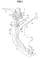
- an endoscope apparatus 1 includes an endoscope 2 used for endoscopy and an endoscope insertion aid 4 which assists insertion of the endoscope 2.
- An insertion portion 3 of the endoscope 2 is inserted into the body, for example, an intestinal tract.
- the endoscope insertion aid 4 is detachably mounted on a distal side of the insertion portion 3 of the endoscope 2.
- the endoscope 2 includes the insertion portion 3 inserted into the intestinal tract and the like, an operation portion 5 provided at a proximal end of the insertion portion 3, and a universal cable 6 which extends form a lateral portion of the operation portion 5.
- the universal cable 6 has a connector (not shown) in an end portion. The connector is detachably connected to a light source device or signal processing device.
- the insertion portion 3 includes a flexible tubular portion 7 which has flexibility and elongated shape, a bending portion 8 which is bendable and provided at a distal end of the flexible tubular portion 7, and a rigid, distal end portion 9 provided at a distal end of the bending portion 8.
- a balloon 10 is mounted on an outer peripheral side on the distal side of the flexible tubular portion 7 of the insertion portion 3 to provide a holding unit for the endoscope insertion aid 4.
- an observation window 11 is provided near the center of a distal end face of the distal end portion 9, and an illumination window 12 and air/water supply nozzle 13 are provided on both sided of the observation window 11.
- a light guide is arranged in the illumination window 12 to transmit illumination light via an illumination lens (not shown).
- the light guide is connected to the light source device by passing through the insertion portion 3 and the like.
- the illumination light generated by the light source device is transmitted through the light guide and emitted from the illumination window 12 to illuminate a field of view range of the observation window 11.
- An objective lens (not shown) is arranged in the observation window 11 and an image pickup device such as a CCD is arranged at image forming position of the objective lens.
- An optical image of an interior of the intestinal tract is formed on an image pickup surface of the CCD.
- a signal cable extends from the CCD.
- the signal cable is electrically connected to the signal processing device after passing through the insertion portion 3 and the like.
- the signal processing device outputs a CCD drive signal.
- the signal processing device converts an image pickup signal produced by the CCD as a result of image pickup into a video signal and outputs the video signal to a monitor. Consequently, an image picked up by the CCD is displayed on a display screen of the monitor.
- An opening portion 14a communicated with a distal opening of a first channel 14 is formed at a distal end of the distal end portion 9, where the first channel 14 provides a treatment instrument channel. Also, an opening of an opening portion 15a is formed in a rear flank of the bending portion 8 along an insertion direction. The opening portion 15a is communicated with a distal opening of a second channel 15 provided in the insertion portion 3.
- the second channel 15 is provided to pass through a thread-like member 19 of the endoscope insertion aid 4.
- the first channel 14 and second channel 15 are arranged along a longitudinal direction of the insertion portion 3.
- a proximal opening of the first channel 14 is communicated with a first channel entrance port 21 shown in Fig. 1 while a proximal opening of the second channel 15 is communicated with a second channel entrance port 22.
- the operation portion 5 has a grasping portion 23.
- the surgeon can operate a bending operation knob 24 in the operation portion 5 by gripping the grasping portion 23.
- the surgeon can bend the bending portion 8 in a desired direction: up, down, left, or right.
- the bending portion 8 is made up of multiple annular, bending pieces coupled rotatably and is designed to bend when the surgeon draws and relaxes a bending wire by rotating operation of the bending operation knob 24.
- the operation portion 5 is provided with an air/water supply button 25 and a suction button 26 used for suction operations.
- an air/water supply button 25 By operating the air/water supply button 25, the surgeon can supply air or water.
- a suction button 26 By operating the suction button 26, the surgeon can suck body fluids and the like through the first channel 14 and its opening portion 14a.
- the first channel 14 can be used as a suction conduit through which fluids are sucked and a conduit through which a treatment instrument is passed. For that, on the rear side, the first channel 14 is bifurcated into a conduit (not shown) which is communicated with the first channel entrance port 21 and a suction conduit (not shown) which extends to a rear end side of the operation portion 5.
- the endoscope apparatus 1 has two channels--the first channel 14 and second channel 15, the endoscope apparatus 1 may have only the second channel 15.
- the second channel 15 can be used not only as a conduit through which the thread-like member 19 is passed, but also as a conduit through which a treatment instrument is passed and a suction conduit through which fluids are sucked as in the case of the first channel 14.
- the endoscope insertion aid 4 includes a balloon tube member 16, balloon 10, thread-like member 19, fluid tube 20, distal-side entanglement prevention member 17, and rear-side entanglement prevention member 18.
- the balloon tube member 16 is a tubular member which allows passage of the insertion portion 3 of the endoscope 2 and inserted insertion portion 3 moves forward and backward relatively along an insertion axis direction.
- the balloon 10 is a holding unit which is provided on an outer surface of the balloon tube member 16.
- the balloon 10 can be inflated and deflated as a fluid is supplied and discharged via the fluid tube 20.
- the thread-like member 19 is connected at one end to the balloon tube member 16. At the other end, the thread-like member 19 is passed into the second channel 15 through the opening portion 15a communicated with the second channel 15 of the insertion portion 3 and extends outward from the second channel entrance port 22 arranged on a proximal end side of the endoscope 2.
- a thread-like member fixing unit (hereinafter abbreviated to a thread fixing unit) 30 is arranged on the proximal end side of the endoscope 2.
- the thread fixing unit 30 restrains the thread-like member 19 protruding from the second channel entrance port 22 and thereby restricts movement of the balloon tube member 16 toward the proximal end side with respect to the insertion portion 3 along the insertion axis.
- the fluid tube 20 doubles as a restraining member, being disposed in such a way as to be able to move relative to the insertion portion 3 along an axis.
- the fluid tube 20 is connected at one end to the balloon tube member 16 and extends at the other end to the proximal end side along an outer peripheral side of the insertion portion 3.
- a tube/conduit member fixing unit (hereinafter abbreviated to a tube fixing unit) 31 holds the balloon tube member 16 at a desired position in the intestinal tract by fixing the above-described other end of the fluid tube 20.
- the endoscope insertion aid 4 may be a disposable one which can be disposed of after a single use or a reusable one which can be reused by being cleaned, disinfected, and sterilized after use.
- the balloon 10 and balloon tube member 16 of the endoscope insertion aid 4 are arranged on the flexible tubular portion 7 closer to the proximal side along the insertion direction than the bending portion 8 so that the bending portion 8 will be exposed.
- the thread-like member 19 connected to the balloon tube member 16 is passed into the second channel entrance port 22 through the opening portion 15a provided in the rear flank of the bending portion 8 along the insertion direction. In this way, the bending portion 8 is exposed without being covered by the balloon 10 to improve insertability into the intestinal tract by efficiently using bending operation of the bending portion 8.
- the balloon 10 and balloon tube member 16 of the endoscope insertion aid 4 may be arranged on the distal side of the insertion portion 3 so as to cover the bending portion 8 as shown as a variation in Fig. 3 .
- the thread-like member 19 connected to the balloon tube member 16 is led to the second channel entrance port 22 after entering the opening portion 15b of the second channel 15 and passing through the second channel 15, where the opening portion 15b is an opening provided in a distal end face of the distal end portion 9.
- the balloon 10 which inflates and deflates as a fluid is supplied and discharged is made of a highly elastic material such as silicon resin. When deflated, the balloon 10 assumes an substantially cylindrical shape. A cylindrical inner peripheral surface of the balloon 10 is supported by the balloon tube member 16 on the distal side and rear side along the insertion direction.
- the balloon tube member 16 is a flexible member made, for example, of silicon resin and formed into a cylindrical shape.
- the balloon tube member 16 is not limited particularly to any material or structure as long as the balloon tube member 16 has flexibility.
- the balloon tube member 16 may be a fluoroplastic tube formed into a helical coil which is detachably fitted over the outer periphery of the flexible tubular portion 7, a fluoroplastic mesh tube, or a fluoroplastic tube harder and less elastic than the balloon 10.
- the fluid tube 20 which is an elongated tube member is disposed in the balloon tube member 16 to supply and discharge the fluid to the balloon 10. Also, the fluid tube 20 has an opening 20a for use to supply and discharge the fluid. The opening 20a is formed at a location which is communicated with a hollow portion in the balloon 10.
- the fluid tube 20 is made, for example, of silicon.
- the balloon tube member 16 and fluid tube 20 may be formed integrally or formed as separate members as shown in Fig. 4 .
- a rear end of the fluid tube 20 is detachably and airtightly connected to a front end of a tube 34 connected to a balloon control pump 33, which is an example of fluid supply/discharge means.
- Operation of the balloon control pump 33 can be controlled by turning on and off a balloon control switch (not shown).
- a balloon control switch By operating the balloon control switch, the surgeon can freely supply a gas such as air from the balloon control pump 33 into the balloon 10 through the fluid tube 20 and thereby inflate the balloon 10 or suck or discharge the fluid from the balloon 10 and thereby deflate the balloon 10.
- the fluid such as air may be supplied and discharged manually using a syringe or the like instead of the balloon control pump 33.
- the distal-side entanglement prevention member 17 is fixed to a distal end portion of the balloon tube member 16.
- the distal-side entanglement prevention member 17, which has a tubular shape, is tapered toward the distal end, forming a tapered portion on the distal side.
- the rear-side entanglement prevention member 18 is fixed to a rear end portion of the balloon tube member 16. Again, the rear-side entanglement prevention member 18, which has a tubular shape, is tapered toward the rear end, forming a tapered portion on the rear side.
- Multiple protrusions 17a are provided in a circumferential direction on an inner peripheral surface of the distal-side entanglement prevention member 17 to reduce a contact area with the insertion portion 3 and thereby reduce friction. Also, multiple protrusions 18a are provided on an inner peripheral surface of the rear-side entanglement prevention member 18 to reduce a contact area with the insertion portion 3 and thereby reduce friction.
- the distal-side entanglement prevention member 17 and rear-side entanglement prevention member 18 can prevent intestinal walls and the like from being entangled when the insertion portion 3 advances into the intestinal tract together with the balloon 10 and balloon tube member 16 or when the balloon 10 and balloon tube member 16 are moved toward the user's hand side along the insertion axis of the insertion portion 3.
- the distal-side entanglement prevention member 17 is provided with a passage hole to pass the thread-like member 19.
- the rear-side entanglement prevention member 18 is provided with a passage hole to pass the fluid tube 20 along the insertion axis.
- one end of the thread-like member 19 is fixed to the distal side of the balloon tube member 16.
- the end of the thread-like member 19 is fixed with an adhesive or the like in a mounting hole (not shown) provided in a distal end face of the balloon tube member 16 or the end of the thread-like member 19 is fixed with an adhesive or the like to a groove provided in an inner peripheral surface of the balloon tube member 16.
- the thread-like member 19 is passed through the distal-side entanglement prevention member 17, and then passed into the second channel 15 of the insertion portion 3 through the opening portion 15a provided in the rear flank of the bending portion 8 along the insertion direction. Then, the other end of the thread-like member 19 is extended outward from the second channel entrance port 22 of the endoscope 2 as shown in Fig. 1 .
- the thread-like member 19, which is configured to be flexible, preferably has such strength and characteristics as not to break even if loads are exerted on the balloon 10 and balloon tube member 16 during insertion into the intestinal tract.
- the balloon 10 is fitted in a predetermined position of the balloon tube member 16 which includes the fluid tube 20 and inner peripheral surface of the balloon 10 is fixed, on the distal side and proximal side, to an outer peripheral surface of the balloon tube member 16 with an adhesive or the like.
- the thread-like member 19 is fixed to the balloon tube member 16. Then, the thread-like member 19 is passed through the distal-side entanglement prevention member 17. In this state, the distal-side entanglement prevention member 17 is fixed to the distal end portion of the balloon tube member 16, for example, with an adhesive or the like.
- the fluid tube 20 extending from the rear side of the balloon tube member 16 is passed into the passage hole of the rear-side entanglement prevention member 18, which is then fixed to a rear end portion of the balloon tube member 16, for example, with an adhesive or the like.
- the method for fixing the balloon 10, distal-side entanglement prevention member 17, and rear-side entanglement prevention member 18 to the balloon tube member 16 is not limited to the use of an adhesive or the like, and another fixing method may be used.
- a main body of the thread fixing unit 30 shown in Figs. 1 and 8 is made, for example, of resin and structured as a rectangular solid.
- the thread fixing unit 30 is provided with a notch 30A having a tapered space between surfaces thereof, slit 30B, and passage hole 30C.
- the notch 30A is formed in a flank of the main body and the slit 30B extends from the notch 30A.
- the passage hole 30C forms an end portion of the slit 30B, being located in the approximate center of the main body.
- the passage hole 30C is designed to be large enough to pass the thread-like member 19, but not large enough to pass a stopper 19a provided at a predetermined position of the thread-like member 19.
- the surgeon provides the stopper 19a at a predetermined position of the thread-like member 19 in advance. Then, as shown in Fig. 8 , the surgeon places the thread-like member 19 protruding from the second channel entrance port 22 in contact with the notch 30A in the thread fixing unit 30 and pushes the thread-like member 19 into the slit 30B.
- position of the stopper 19a with respect to the thread-like member 19 can be changed as required.
- position of the stopper 19a it is possible to change restricting position of the balloon tube member 16 with respect to the insertion portion 3.
- the surgeon can remove the thread fixing unit 30 from the thread-like member 19 by reversing the fixing operation described above.
- the removal of the thread fixing unit 30 from the thread-like member 19 derestricts the movement of the balloon tube member 16 toward the proximal end side with respect to the insertion portion 3 along the insertion axis.
- the tube fixing unit 31 shown in Fig. 6 includes a pedestal body 31A and a restraining portion 31C provided with a V groove 31B.
- the V groove 31B is erected on a flat surface of the pedestal body 31A to restrain and hold the fluid tube 20.
- the tube fixing unit 31 is placed on or near a patient bed. Therefore, it is preferable that the tube fixing unit 31 is heavy enough not to move easily. If the tube fixing unit 31 is not heavy enough, preferably the tube fixing unit 31 is fixed to or near the patient bed so as not to move easily.
- the surgeon pushes the fluid tube 20 into the V groove 31B of the tube fixing unit 31. Consequently, the fluid tube 20 is slightly squeezed by the V groove 31B and thereby fixed in the V groove 31B securely.
- the configuration of the tube fixing unit 31 is not limited to the one shown in Fig. 6 , and any other configuration may be used as long as the fluid tube 20 can be fixed securely at a desired position.
- surgeon can release the balloon tube member 16 held at the desired position in the intestinal tract by removing the fluid tube 20 from the V groove 31B of the tube fixing unit 31.
- the fluid tube 20 is provided with a fixing unit 32 as shown in Fig. 7 .
- the fixing unit 32 fixes and holds the fluid tube 20 to or near a patient bed.
- the fixing unit 32 includes a main body 32A, a holding unit 32a which, being provided integrally with the main body 32A, allows passage of the fluid tube 20, and a suction cup unit 32b provided on a bottom surface of the main body 32A.
- the suction cup unit 32b is configured to be fixed to a planar member by suction, but the fixing unit 32 is not limited to a configuration in which the main body 32A has the suction cup unit 32b, and may be configured, for example, to be an attachable/detachable adhesive member.
- the configuration of the fixing unit 32 is not limited to the one shown in Fig. 7 , and any other configuration may be used as long as the fluid tube 20 can be fixed at a desired position.
- the endoscope apparatus 1 according to the present embodiment can restrict the movement of the balloon tube member 16 of the endoscope insertion aid 4 toward the proximal end side with respect to the insertion portion 3 along the insertion axis.
- the endoscope apparatus 1 enables the movement of the balloon tube member 16 toward the proximal end side with respect to the insertion portion 3 along the insertion axis.
- the endoscope apparatus 1 is configured such that when the movement of the balloon tube member 16 is restricted, it becomes easier to insert the insertion portion 3 together with the balloon tube member 16 of the endoscope insertion aid 4 into the intestinal tract. On the other hand, when the movement of the balloon tube member 16 is derestricted, it becomes easier to move the insertion portion 3 forward reliably with respect to the balloon tube member 16.
- the endoscope apparatus 1 is configured such that the balloon tube member 16 can be held at a desired position in the intestinal tract as the fluid tube 20 is fixed with the tube fixing unit 31 and that the balloon tube member 16 can be moved in the intestinal tract as the fluid tube 20 is released from the tube fixing unit 31.
- the endoscope apparatus 1 is configured such that when the fluid tube 20 is unfixed, allowing the fluid tube 20 to be drawn toward the user's hand side, the intestinal tract held by the inflated balloon 10 can be hauled in easily. On the other hand, when the fluid tube 20 is fixed, holding the intestinal tract in the hauled state, it becomes easy to straighten the intestinal tract and thereby help insert the endoscope.
- the thread-like member 19 and thread fixing unit 30 are used to restrict and derestrict the movement of the balloon tube member 16 toward the proximal end side with respect to the insertion portion 3 along the insertion axis
- the method for restricting and derestricting the movement of the balloon tube member 16 is not limited thereto.
- a separate inner balloon may be provided on an inner peripheral side of the balloon tube member 16 to restrict and derestrict the movement of the balloon tube member 16 relative to the insertion portion 3 by inflating and deflating the inner balloon, as with an embodiment described later.
- the surgeon may restrain and release the thread-like member 19 to/from the second channel entrance port 22 with fingers without using the thread fixing unit 30.
- the thread fixing unit 30 may be configured to be able to mechanically draw, restrain, and release the thread-like member 19, as with a variation of the thread fixing unit 30 described later. In that case, the thread-like member 19 may be drawn, restrained, and released electrically.
- FIG. 13 is a diagram showing how the intestinal tract is hauled in and straightened by drawing the insertion portion and fluid tube in a state shown in Fig. 12 ;
- Fig. 14 is a diagram showing how the balloon tube member is locked by holding the fluid tube using the tube fixing member in a state shown in Fig. 13 ;
- Fig. 15 is a diagram showing how the insertion portion is inserted further into the splenic flexure in a deep part of the intestinal tract by releasing the thread-like member from the thread fixing unit in a state shown in Fig. 14 .
- the thread-like member 19 connected to the balloon tube member 16 is passed into the second channel 15 through the opening portion 15a of the second channel 15 provided in the rear flank of the bending portion 8 along the insertion direction as shown in Fig. 2 and is led out of the second channel entrance port 22 as shown in Fig. 1 .
- the endoscope insertion aid 4 is fitted over a distal outer peripheral surface, i.e., an outer peripheral surface of the flexible tubular portion 7 on the rear side of the bending portion 8, so that the bending portion 8 of the endoscope 2 will be exposed.
- the fluid tube 20 of the endoscope insertion aid 4 extends to the user's hand side of the insertion portion 3. This allows the surgeon to grip and draw the fluid tube 20.
- the surgeon inserts the endoscope 2, starting from the distal side, into the intestinal tract with the balloon 10 deflated as shown in Fig. 10 .
- the surgeon inserts a distal end portion 9 of the insertion portion 3 of the endoscope 2 through the anus 51 into the rectum 52 and further toward the sigmoid colon portion 53 using hand manipulation, bending operation, and the like.
- the distal end portion 9 of the endoscope 2 approaches the sigmoid colon portion 53 into which it is difficult to insert the insertion portion 3.
- the insertion portion 3 is pushed in, since a bent portion between the rectum 52 and sigmoid colon portion 53 has high mobility, the insertion portion 3 is pushed further into the intestinal tract, causing a bent portion to be formed between the sigmoid colon portion 53 and the descending colon portion 54 which has low mobility.
- the surgeon turns on the balloon control switch (not shown) to drive the balloon control pump 33. Consequently, the balloon control pump 33 supplies a fluid such as air into the balloon 10 via the fluid tube 20, thereby starting to inflate the balloon 10.
- the balloon 10 inflates and holds the sigmoid colon portion 53, a part of the intestinal tract, from inside.
- the bent portion formed at the junction between the sigmoid colon portion 53 and descending colon portion 54 is extended. That is, the sigmoid colon portion 53 is straightened between the junction H1 with the descending colon portion 54 and a junction L1 with the rectum 52.
- the surgeon fixes the fluid tube by pushing the fluid tube 20 in the V groove 31 B of the tube fixing unit 31 fixed to the patient bed or the like.
- the surgeon inserts the insertion portion 3 movable with respect to the endoscope insertion aid 4 into a deeper part. Consequently, the insertion portion 3 is inserted through the descending colon portion 54 toward the splenic flexure 56 located at the junction between the descending colon portion 54 and the transverse colon portion 55 which has high mobility.
- insertion operation assisted by the endoscope insertion aid 4 makes it easy to straighten the sigmoid colon portion 53 into which insertion is difficult.
- straightening the sigmoid colon portion 53 it becomes easy to advance the insertion portion 3 deep into the intestinal tract by passing through the sigmoid colon portion 53.
- the surgeon deflates the balloon 10, draws the thread-like member 19 slowly, and thereby moves the balloon tube member 16 to the distal side of the insertion portion 3.
- the surgeon holds the thread-like member 19 using the thread fixing unit 30, thereby fixes the balloon tube member 16 with respect to the insertion portion 3, and inserts the insertion portion 3 again, using hand manipulation, bending operation, and the like, into the splenic flexure 56 located at the junction between the descending colon portion 54 and the transverse colon portion 55 which has high mobility.
- the surgeon can insert the distal end portion 9 of the insertion portion 3 into a deep part of the intestinal tract near the cecum portion 59 by passing through the hepatic flexure 57 located at the junction between the transverse colon portion 55 and ascending colon 58.
- the surgeon may insert the insertion portion 3 until the insertion portion 3 approaches the cecum portion 59, with the sigmoid colon portion 53 held and straightened by the balloon 10.
- Figs. 16 to 18 are explanatory diagrams illustrating the operation of pulling out the insertion portion 3 using the endoscope insertion aid 4 according to the first embodiment, where Fig. 16 is a diagram showing how the distal side of the insertion portion 3 has reached the cecum portion in a state shown in Fig. 15 ; Fig. 17 is a diagram showing how the insertion portion is drawn by releasing the fluid tube from the tube fixing member in the state shown in Fig. 15 ; and Fig. 17 is a diagram showing how the insertion portion and fluid tube are drawn and pulled out of the anus by deflating the balloon in a state shown in Fig. 16 .
- the surgeon restricts the movement of the balloon tube member 16 with respect to the insertion portion 3 by restraining the thread-like member 19 with the thread fixing unit 30 again and draws the fluid tube 20 together with the insertion portion 3.
- the endoscope insertion aid 4 includes the thread fixing unit 30 which holds the thread-like member 19 and thereby restricts the movement of the balloon tube member 16 toward the proximal end side with respect to the insertion portion 3 along the insertion axis, and the tube fixing unit 31 which fixes the fluid tube 20 and thereby holds the balloon tube member 16 at a desired position in the intestinal tract, in addition to the balloon 10, balloon tube member 16, thread-like member 19, and fluid tube 20. Consequently, after the intestinal tract held by the balloon 10 is hauled in by drawing the fluid tube 20, the state of the intestinal tract can be maintained using a simple configuration and operation method. This makes it possible to easily straighten the intestinal tract and smoothly insert the insertion portion 3 of the endoscope 2 deep into the intestinal tract.
- the insertion portion 3 of the endoscope 2 is inserted into the large intestine with the help of the endoscope insertion aid 4,
- the lumen into which the insertion portion 3 equipped with the endoscope insertion aid 4 is inserted is not limited to the large intestine, and may be the lumen running from oral cavity, the esophagus, the stomach and to the small intestine.
- the thread fixing unit 30 which has a simple rectangular body is configured to restrain and release the thread-like member 19.
- the thread fixing unit may be configured such as allow the surgeon to adjust an amount of movement of the balloon tube member 16 with respect to the insertion portion 3 during a return operation in which the thread-like member 19 is drawn and perform the return operation smoothly, as shown in an embodiment described later.
- Figs. 19 to 31 concern a second embodiment, where Fig. 19 is an explanatory diagram showing how an improved thread-like member is led out of a second channel entrance port;
- Fig. 20 is a perspective view illustrating a configuration of an improved rotary-dial thread fixing unit;
- Fig. 21 is a perspective view showing how the rotary-dial thread fixing unit shown in Fig. 20 is mounted near the second channel entrance port of the endoscope;
- Fig. 22 is a sectional view of a mounting portion of the endoscope and rotary-dial thread fixing unit shown in Fig. 21 ;
- Fig. 23 is an exploded block diagram showing a concrete configuration of the rotary-dial thread fixing unit shown in Fig. 20 ;
- Fig. 19 is an explanatory diagram showing how an improved thread-like member is led out of a second channel entrance port;
- Fig. 20 is a perspective view illustrating a configuration of an improved rotary-dial thread fixing unit;
- Fig. 21 is a perspective view showing how
- FIG. 24 is a block diagram of the rotary-dial thread fixing unit shown in Fig. 23 as viewed from a mounting direction of the endoscope;
- Fig. 25 is a block diagram of the rotary-dial thread fixing unit shown in Fig. 23 as viewed from above;
- Fig. 26 is a block diagram of the rotary-dial thread fixing unit shown in Fig. 23 as viewed from below;
- Fig. 27 is an exploded perspective view illustrating a configuration of principal part of the rotary-dial thread fixing unit shown in Fig. 20 ;
- Fig. 28 is a sectional view taken along line XXVIII - XXVIII in Fig. 23 ;
- Fig. 29 is a sectional view taken along line XXIX - XXIX in Fig.
- Fig. 30 is a sectional view near an elastic portion of the thread-like member used in the present embodiment
- Fig. 31 is an explanatory diagram illustrating the operation of restraining the elastic portion of the thread-like member in a grooved portion of a rotating shaft of the thread fixing unit.
- an endoscope apparatus 1 has a thread-like member 19 improved over the one according to the first embodiment and includes a rotary-dial thread fixing unit 60 instead of the thread fixing unit 30 according to the first embodiment.
- the thread-like member 19 used in the present embodiment includes an elastic portion 19c and marker 19b.
- the elastic portion 19c is made of an elastic material and provided on a proximal side of the thread-like member 19.
- the elastic portion 19c and the marker 19b is provided closer to the distal side a predetermined distance away from the elastic portion 19c.
- the elastic portion 19c covers an outer surface of the thread-like member 19, for example, as shown in Fig. 30 .
- a recessed portion 19x is provided near the longitudinal center of the elastic portion 19c to make it easy to restrain the elastic portion 19c in a groove 66 formed in a rotating shaft 62a shown in Fig. 31 .
- the marker 19b which is intended to be used by the surgeon for the purpose of identification, is created by applying a paint or colored tape to the outer surface of the thread-like member 19.
- the rotary-dial thread fixing unit 60 is configured to be able to restrain the thread-like member 19 configured as described above, hold the balloon tube member 16 by winding the thread-like member 19, and release the thread-like member 19 from the restraint.
- the rotary-dial thread fixing unit 60 is detachably mounted on a predetermined portion of a grasping portion 23 in which the second channel entrance port 22 of the endoscope 2 is provided.
- the rotary-dial thread fixing unit 60 is mounted in such a way as to cover the second channel entrance port 22 along arrow C shown in Figs. 19 and 20 .
- the endoscope 2 may have two channel entrance ports 21 and 22 as with the first embodiment.
- the rotary-dial thread fixing unit 60 needs to be configured according to its shape.
- the rotary-dial thread fixing unit 60 mainly includes a main body 60A, fitting unit 60B, mounting belt 61, rotary dial 62, and slide lock 63.
- the main body 60A is detachably fitted over a lower part of the grasping portion 23 of the endoscope 2.
- the fitting unit 60B which is attached to the main body 60A, is fitted over the grasping portion 23 near the second channel entrance port 22 in such a way as to cover the second channel entrance port 22.
- the mounting belt 61 is used to detachably mount the main body 60A on the grasping portion 23.
- the rotary dial 62 is used to wind the thread-like member 19 by being provided on the fitting unit 60B in such a way as to be rotatable in a direction of arrow A.
- the slide lock 63 which is slidable with respect to the fitting unit 60B as indicated by arrow B, is used to restrict and derestrict rotation of the rotary dial 62.
- the main body 60A and fitting unit 60B are configured to be, for example, substantially channel-shaped as shown in Figs. 20 to 22 so that the main body 60A and fitting unit 60B can be fitted over the grasping portion 23 at a location near the second channel entrance port 22.
- a contact portion 60E is formed on an inner surface of the main body 60A as shown in Fig. 24 .
- the contact portion 60E is shaped to conform to an R-shaped form of the grasping portion 23. Consequently, the main body 60A is placed in surface contact with an outer surface of the grasping portion 23, and thus mounted firmly on the grasping portion 23.
- hook portions 61a are provided on both flanks of the main body 60A.
- the hook portions 61 a are designed to be restrained in restraining holes 61b in the mounting belt 61.
- the mounting belt 61 is made of an elastic material which has a predetermined elasticity.
- the restraining holes 61b are formed in both sides of the mounting belt 61 to restrain the hook portions 61 a of the main body 60A.
- the mounting belt 61 may be made of any material instead of an elastic material as long as the main body 60A can be mounted securely on the grasping portion 23.
- the rotary-dial thread fixing unit 60 is fitted over the grasping portion 23 of the endoscope 2 with the contact portion 60E of the main body 60A placed in contact with the surface of the grasping portion 23.
- the mounting belt 61 with one side mounted on one of the hook portions 61 a of the main body 60A in advance, is wound around the grasping portion 23 as shown in Fig. 22 .
- the other restraining hole 61 b of the mounting belt 61 is fitted over the other hook portion 61 a. Consequently, the rotary-dial thread fixing unit 60 is mounted on the grasping portion 23 as shown in Fig. 21 .
- the fitting unit 60B is attached to the main body 60A at a predetermined angle to the main body 60A to conform to shape of an entrance portion near the second channel entrance port 22.
- an entrance port 60D is formed in an inner surface between the main body 60A and fitting unit 60B in such a way as to align with the second channel entrance port 22.
- passage holes 60b are formed in both flanks of the fitting unit 60B to accept the rotating shaft 62a of the rotary dial 62. Also, in that flank on which the rotary dial 62 is arranged, a pair of retaining grooves 60C are provided on opposite sides of the passage hole 60b.
- the retaining grooves 60C are designed to be fitted with restraining hooks 63a of the slide lock 63.
- the slide lock 63 is formed, for example, by bending a plate member into a U shape as shown in Fig. 23 .
- a fixing nut 64 fixed to the rotating shaft 62a (described later) is placed in an opening portion 63b of the slide lock 63.
- the restraining hooks 63a are provided on that flank on the opening side of the slide lock 63 which corresponds to the retaining grooves of the fitting unit 60B.
- the slide lock 63 is slidably arranged on the fitting unit 60B.
- longitudinal length of the retaining grooves 60C and length of the restraining hooks 63a are set such that the restraining hooks 63a can move a predetermined amount in the retaining grooves 60C.
- the slide lock 63 is made of a rigid material. Also, the opening portion 63b and restraining hooks 63a of the slide lock 63 have been dimensioned according to geometries of the fixing nut 64 and the retaining grooves 60C in the fitting unit 60B, respectively.
- a width dimension of the opening portion 63b of the slide lock 63 is set such that opposite sides of the fixing nut 64 will be placed in the opening portion 63b with some clearance.
- the fixing nut 64 when placed in the opening portion 63b of the slide lock 63 can restrict rotation of the rotating shaft 62a.
- the rotary dial 62 is integrally fixed to a proximal end portion 62b of the rotating shaft 62a.
- the rotating shaft 62a is passed through the passage holes 60b of the fitting unit 60B.
- the rotating shaft 62a is rotatably arranged in the fitting unit 60B, with the fixing nut 64 and a fixing nut 65 placed on opposite flanks of the fitting unit 60B, where the fixing nut 64 is fixed to a predetermined position on the rotating shaft 62a.
- the slide lock 63 can slide as indicated by arrow D and the rotary dial 62 can rotate in the illustrated placement location.
- the fixing nut 65 is fixed by being screwed onto a threaded portion 62c of the rotating shaft 62a led out of a flank of the fitting unit 60B.
- the rotating shaft 62a has a groove 66 formed in a location corresponding to the entrance port 60D.
- the elastic portion 19c provided on the proximal side of the thread-like member 19 is placed in the groove 66.
- the surgeon inserts the recessed portion 19x of the elastic portion 19c into the groove 66 by gripping an end portion of the thread-like member 19 as shown in Fig. 31 .
- the groove 66 is configured to be narrower than the recessed portion 19x of the elastic portion 19c, when the recessed portion 19x is pushed into the groove 66, the thread-like member 19 is connected securely to the rotating shaft 62a.
- Fig. 32 is an explanatory diagram showing a maximum stroke through which the balloon tube member can move with respect to the insertion portion
- Fig. 33 is an explanatory diagram showing a return of the balloon tube member when the thread-like member is wound by rotating a rotary dial.
- the surgeon places the balloon 10 and balloon tube member 16 of the endoscope insertion aid 4 a distance LO away from the rear side of the bending portion 8 as shown in Fig. 32 in contrast to an initial position shown in Fig. 2 and restrains the elastic portion 19c of the thread-like member 19 in the groove 66 of the rotating shaft 62a. Consequently, the balloon tube member 16 is placed away from the insertion portion 3 by the maximum stroke LO.
- travel distance LX of the balloon tube member 16 per rotation of the rotary dial 62 is measured in advance, the travel distance of the balloon tube member 16, for example, in the intestinal tract during a return operation can be recognized in terms of the number of rotations made by the rotary dial 62, making it possible to improve the return operation.
- the marker 19b on the thread-like member 19 is intended to let the surgeon know that the balloon tube member 16 is located at the initial position shown in Fig. 2 .
- the surgeon can restrict the rotation of the rotating shaft 62a by moving the slide lock 63 until the fixing nut 64 is placed in contact with an inner surface of the slide lock 63 and thereby hold the balloon tube member 16 at the initial position shown in Fig. 2 .
- the distal end portion 9 of the insertion portion 3 is inserted into the intestinal tract with the balloon tube member 16 held at the initial position shown in Fig. 2 , in the same way as in the first embodiment.
- the surgeon moves the slide lock 63 of the rotary-dial thread fixing unit 60, thereby places the fixing nut 64 out of the opening portion 63b, and thereby derestricts rotation of the rotating shaft 62a and at the same time, derestricts the movement of the balloon tube member 16 with respect to the insertion portion 3.
- the surgeon can perform an insertion operation so as to insert the insertion portion 3 into a deeper part.
- the surgeon can rotate the rotary dial 62 slowly. That is, the thread-like member 19 is wound around the rotating shaft 62a as the surgeon rotate the rotary dial 62, and consequently the balloon tube member 16 moves toward the distal side of the insertion portion 3 as indicated by a solid line in Fig. 33 .
- the surgeon moves the slide lock 63 of the rotary-dial thread fixing unit 60, thereby places the fixing nut 64 in the opening portion 63b again, and thereby restricts the movement of the balloon tube member 16 with respect to the insertion portion 3.
- the surgeon can do so with the balloon tube member 16 locked using the rotary-dial thread fixing unit 60.
- the second embodiment provides the advantage of being able to return the balloon 10 and balloon tube member 16 easily and simply in the intestinal tract using the rotary-dial thread fixing unit 60.
- multiple thread-like members 19 may be connected to the balloon tube member 16.
- two thread-like members 19 may be provided in opposing relation to each other on the outer peripheral side of the insertion portion 3, with appropriate channels provided in the insertion portion 3. The use of two thread-like members 19 makes it possible to return the balloon tube member 16 reliably with a smaller tensile force.
- An endoscope insertion aid 4B described below can restrict and derestrict the movement of the balloon tube member 16 with respect to the insertion portion 3 without using any of the thread-like member 19, thread fixing unit 30, and rotary-dial thread fixing unit 60 used in the first and/or second embodiments.
- Figs. 34 to 37 concern a third embodiment, where Fig. 34 is a partial cutaway, sectional view illustrating a configuration of an endoscope insertion aid equipped with inner balloons instead of the thread-like member;
- Fig. 35 is a block diagram as viewed along arrow XXXV in Fig. 34 ;
- Fig. 36 is a sectional view taken along line XXXVI - XXXVI in Fig. 34 ;
- Fig. 37 is an exploded perspective view of the endoscope insertion aid in Fig. 34 .
- An endoscope apparatus 1 is equipped with the endoscope insertion aid 4B shown in Fig. 34 .
- the endoscope insertion aid 4B which has substantially the same configuration as the endoscope insertion aid 4, includes an inner balloon unit 70 instead of the thread-like member 19 and thread fixing unit 30 used to restrict and derestrict the movement of the balloon tube member 16.
- the inner balloon unit 70 includes two inner balloons 70A and 70B which can be inflated and deflated as a fluid is supplied and discharged.
- the inner balloon unit 70 is not limited to the two inner balloons 70A and 70B, and may have one or more than two balloons.
- the two inner balloons 70A and 70B are provided on an inner peripheral side of the balloon tube member 16 as shown in Figs. 34 and 36 .
- the fluid tube 20 provided for the balloon tube member 16 includes an inner-supply conduit 20d used to supply the fluid to the inner balloons 70A and 70B as well as an outer-supply conduit 20c used to supply the fluid to the balloon 10.
- the inner-supply conduit 20d has openings 20b which are communicated with hollow portions in the inner balloons 70A and 70B, respectively, as shown in Figs. 34 and 36 , to supply and discharge the fluid to/from the hollow portions.
- the fluid tube 20 has two different conduits--the inner-supply conduit 20d and outer-supply conduit 20c, two balloon control pumps 33 are provided in a rear end portion of the fluid tube 20, the one being connected to the outer-supply conduit 20c and the other being connected to the inner-supply conduit 20d. This makes it possible to control inflation/deflation of the outer balloon 10 and inflation/deflation of the inner balloons 70A and 70B separately.
- An assembly method of the endoscope insertion aid 4B is substantially the same as the first embodiment.
- the inner balloon unit 70 is fixed to the inner peripheral side of the balloon tube member 16 with an adhesive or the like as shown in Fig. 37 .
- the endoscope insertion aid 4B does not need to connect the thread-like member 19.
- the endoscope apparatus 1 instead of restricting and derestricting the movement of the balloon tube member 16 using the thread-like member 19 and thread fixing unit 30 as in the case of the first embodiment, the endoscope apparatus 1 according to the present embodiment restricts and derestricts the movement of the balloon tube member 16 with respect to the insertion portion 3 by inflating and deflating the inner balloons 70A and 70B of the inner balloon unit 70 via fluid supply and discharge thereto/therefrom.
- the third embodiment can restrict and derestrict the movement of the balloon tube member 16 with respect to the insertion portion 3 using the inner balloon unit 70 instead of the thread-like member 19 and thread fixing unit 30 according to the first embodiment, and thereby provide the same advantage as the first embodiment.
Abstract
Description
- The present invention relates to an endoscope insertion aid and endoscope apparatus suitable for smoothly inserting an insertion portion of an endoscope into an intestinal tract such as the large intestine or small intestine.
- Generally, an endoscope includes an operation portion intended to be gripped by a surgeon and equipped with various operation switches and the like, and an insertion portion inserted into a body cavity. Starting from a distal end, the insertion portion includes a distal end portion, bending portion, and flexible tubular portion, all of which are provided continuously. The flexible tubular portion has flexibility and elongated shape, extending from the operation portion. The bending portion is provided continuously with a distal end of the flexible tubular portion and configured to be bendable in left and right or up and down directions by being operated from the operation portion. The distal end portion has a distal rigid portion configured to be rigid and provided continuously with a distal end of the bending portion. The endoscope is designed to be inserted into the body through the anus, mouth, or nose to allow the surgeon to observe or treat predetermined sites.
- Conventionally, when inserting the insertion portion of the endoscope configured as described above into an intestinal tract, the surgeon inserts the insertion portion gradually into the body of a patient by applying a force to the insertion portion from outside the body.
- However, the intestinal tract into which the insertion portion of the endoscope is pushed is a soft, internally narrow, long, and intricately winding organ which is not secured to the body. Consequently, when the surgeon pushes the insertion portion of the endoscope into the intestinal tract, the intestinal tract may be moved or squeezed in a forward direction. In that case, when the surgeon relaxes pushing force, the plunged insertion portion may be returned to its original position by reaction force of the intestinal tract, making it difficult to move forward. In particular, the deeper in the intestinal tract, the harder the plunged insertion portion is pushed back. This makes it difficult to insert the insertion portion into a deep part, resulting in longer endoscopy time.
- To solve this problem, Japanese Patent Application Laid-Open Publication No.
2007-37649 - With the endoscope insertion aid proposed in Japanese Patent Application Laid-Open Publication No.
2007-37649 - With the endoscope insertion aid, when the shaft is drawn to the user's hand side with the inflated balloon secured to the intestinal tract and the like, the insertion portion of the endoscope is moved toward the balloon, allowing the insertion portion to be inserted deep into the intestinal tract.
- With the endoscope insertion aid proposed in Japanese Patent Application Laid-Open Publication No.
2007-37649 - Depending on bend angle of the bending portion, the force of the bending portion or distal end portion holding the intestinal tract is too weak to hold the intestinal tract securely. In such a case, the hauled intestinal tract is pushed back, making it difficult to smoothly insert the insertion portion of the endoscope deep into the intestinal tract.
- On the other hand, too large a bend angle of the bending portion may cause pain to the patient, or adverse effects on forward movement of the balloon by subsequent push operation.
- In addition to the one proposed in Japanese Patent Application Laid-Open Publication No.
2007-37649 - However, such an overtube with a balloon has a slippery interior. Besides, the overtube for the large intestine is configured to cover the entire length of the insertion portion, making it difficult to pull the overtube and insertion portion together when twisting the insertion portion or hauling in the intestinal tract using the balloon or otherwise operate the endoscope together with the overtube.
- The present invention has been made in view of the above problems and has an object to provide an endoscope insertion aid and endoscope apparatus which allow the surgeon to draw and haul in an intestinal tract using an insertion portion of an endoscope with the intestinal tract held by a balloon, keep the hauled intestinal tract by fixing a restraining member with a restraining member fixing unit, and thereby straighten the intestinal tract easily and insert the insertion portion deep into the intestinal tract smoothly.
- The present invention provides an endoscope insertion aid including: a tubular member which allows an insertion portion of an endoscope to be passed through and can move forward and backward relatively along an insertion axis of the passed insertion portion; a holding unit which, being provided on an outer peripheral side of the tubular member, can be inflated and deflated with supply and discharge of a fluid; a thread-like member which, being connected at one end to the tubular member and passed at the other end into a channel in the insertion portion through an opening portion communicated with the channel, extends from an opening of the channel, the opening being arranged on a proximal end side of the endoscope; a thread-like member fixing unit which restrains the thread-like member extending from the channel opening provided on the proximal end side of the endoscope and thereby restricts movement of the tubular member toward the proximal end side with respect to the insertion portion along the insertion axis; a restraining member which supplies and discharges the fluid into/from the holding unit, being disposed in such a way as to be able to move relative to the insertion portion along an axis, being connected at one end to the tubular member, and extending at the other end to the proximal end side along an outer peripheral side of the insertion portion; and a restraining member fixing unit which holds the tubular member at a desired position in an intestinal tract by fixing the other end of the restraining member.
- The above and other objects, features and advantages of the invention will become more clearly understood from the following description referring to the accompanying drawings.
-
-
Fig. 1 is a diagram showing an overall configuration of an endoscope apparatus equipped with an endoscope insertion aid according to a first embodiment of the present invention; -
Fig. 2 is a perspective view illustrating a configuration of the endoscope insertion aid mounted on a proximal side of a bending portion of an insertion portion; -
Fig. 3 is a perspective view showing a variation of the endoscope insertion aid which differs fromFig. 2 in placement location with respect to the insertion portion; -
Fig. 4 is partial sectional view illustrating the configuration of the endoscope insertion aid inserted in the insertion portion shown inFig. 2 ; -
Fig. 5 is an exploded perspective view illustrating the configuration of the endoscope insertion aid shown inFig. 2 ; -
Fig. 6 is a perspective view illustrating a configuration of a restraining member fixing unit which restricts the restraining member; -
Fig. 7 is a perspective view illustrating a configuration of a fixing unit which fixes a thread-like member; -
Fig. 8 is a perspective view illustrating a configuration of a thread-like member restricting unit which restricts the thread-like member; -
Fig. 9 is a diagram showing how the thread-like member is restrained; -
Fig. 10 is a diagram illustrating how the insertion portion is inserted using the endoscope insertion aid according to the first embodiment, where the insertion portion is inserted through the anus with a balloon tube member fixed; -
Fig. 11 is a diagram showing how the insertion portion is inserted from the rectum to the sigmoid colon portion by bending operation and the like from a state shown inFig. 10 ; -
Fig. 12 is a diagram showing how the sigmoid colon portion is held by inflating a balloon in a state shown inFig. 11 ; -
Fig. 13 is a diagram showing how an intestinal tract is hauled in and straightened by drawing the insertion portion and fluid tube in a state shown inFig. 12 ; -
Fig. 14 is a diagram showing how the balloon tube member is locked by holding the fluid tube using a tube fixing member in a state shown inFig. 13 ; -
Fig. 15 is a diagram showing how the insertion portion is inserted further into the splenic flexure in a deep part of the intestinal tract by releasing the thread-like member from a thread fixing unit in a state shown inFig. 14 ; -
Fig. 16 is a diagram illustrating how the insertion portion is pulled out using the endoscope insertion aid according to a first embodiment, where a distal side of the insertion portion has reached the cecum in a state shown inFig. 15 ; -
Fig. 17 is a diagram showing how the insertion portion is drawn by releasing the fluid tube from the tube fixing member in the state shown inFig. 15 ; -
Fig. 18 is a diagram showing how the insertion portion and fluid tube are drawn and pulled out of the anus by deflating the balloon in a state shown inFig. 16 ; -
Fig. 19 is an explanatory diagram showing how an improved thread-like member is led out of a second channel entrance port, according to a second embodiment of the present invention; -
Fig. 20 is a perspective view illustrating a configuration of an improved rotary-dial thread fixing unit; -
Fig. 21 is a perspective view showing how the rotary-dial thread fixing unit shown inFig. 20 is mounted near the second channel entrance port of the endoscope; -
Fig. 22 is a sectional view of a mounting portion of the endoscope and rotary-dial thread fixing unit shown inFig. 21 ; -
Fig. 23 is an exploded block diagram showing a concrete configuration of the rotary-dial thread fixing unit shown inFig. 20 ; -
Fig. 24 is a block diagram of the rotary-dial thread fixing unit shown inFig. 23 as viewed from a mounting direction of the endoscope; -
Fig. 25 is a block diagram of the rotary-dial thread fixing unit shown inFig. 23 as viewed from above; -
Fig. 26 is a block diagram of the rotary-dial thread fixing unit shown inFig. 23 as viewed from below; -
Fig. 27 is an exploded perspective view illustrating a configuration of principal part of the rotary-dial thread fixing unit shown inFig. 20 ; -
Fig. 28 is a sectional view taken along line XXVIII - XXVIII inFig. 23 ; -
Fig. 29 is a sectional view taken along line XXIX - XXIX inFig. 28 ; -
Fig. 30 is a sectional view near an elastic portion of the thread-like member used in the present embodiment; -
Fig. 31 is an explanatory diagram illustrating the operation of restraining the elastic portion of the thread-like member in a grooved portion of a rotating shaft of the thread fixing unit; -
Fig. 32 is an explanatory diagram showing a maximum stroke through which the balloon tube member can move with respect to the insertion portion; -
Fig. 33 is an explanatory diagram showing a return of the balloon tube member when the thread-like member is wound by rotating a rotary dial; -
Fig. 34 is a partial cutaway, sectional view illustrating a configuration of an endoscope insertion aid equipped with inner balloons instead of the thread-like member, according to a third embodiment of the present invention; -
Fig. 35 is a block diagram as viewed along arrow XXXV inFig. 34 ; -
Fig. 36 is a sectional view taken along line XXXVI - XXXVI inFig. 34 ; and -
Fig. 37 is an exploded perspective view of the endoscope insertion aid inFig. 34 . - Embodiments of the present invention will be described below with reference to the drawings.
- As shown in
Fig. 1 , anendoscope apparatus 1 according to a first embodiment includes anendoscope 2 used for endoscopy and anendoscope insertion aid 4 which assists insertion of theendoscope 2. Aninsertion portion 3 of theendoscope 2 is inserted into the body, for example, an intestinal tract. Theendoscope insertion aid 4 is detachably mounted on a distal side of theinsertion portion 3 of theendoscope 2. - The
endoscope 2 includes theinsertion portion 3 inserted into the intestinal tract and the like, anoperation portion 5 provided at a proximal end of theinsertion portion 3, and auniversal cable 6 which extends form a lateral portion of theoperation portion 5. Theuniversal cable 6 has a connector (not shown) in an end portion. The connector is detachably connected to a light source device or signal processing device. - The
insertion portion 3 includes a flexibletubular portion 7 which has flexibility and elongated shape, a bendingportion 8 which is bendable and provided at a distal end of the flexibletubular portion 7, and a rigid,distal end portion 9 provided at a distal end of the bendingportion 8. - As shown in
Fig. 1 , aballoon 10 is mounted on an outer peripheral side on the distal side of the flexibletubular portion 7 of theinsertion portion 3 to provide a holding unit for theendoscope insertion aid 4. - As shown in
Fig. 2 , anobservation window 11 is provided near the center of a distal end face of thedistal end portion 9, and anillumination window 12 and air/water supply nozzle 13 are provided on both sided of theobservation window 11. - A light guide is arranged in the
illumination window 12 to transmit illumination light via an illumination lens (not shown). The light guide is connected to the light source device by passing through theinsertion portion 3 and the like. The illumination light generated by the light source device is transmitted through the light guide and emitted from theillumination window 12 to illuminate a field of view range of theobservation window 11. - An objective lens (not shown) is arranged in the
observation window 11 and an image pickup device such as a CCD is arranged at image forming position of the objective lens. An optical image of an interior of the intestinal tract is formed on an image pickup surface of the CCD. - A signal cable extends from the CCD. The signal cable is electrically connected to the signal processing device after passing through the
insertion portion 3 and the like. The signal processing device outputs a CCD drive signal. Also, the signal processing device converts an image pickup signal produced by the CCD as a result of image pickup into a video signal and outputs the video signal to a monitor. Consequently, an image picked up by the CCD is displayed on a display screen of the monitor. - An
opening portion 14a communicated with a distal opening of afirst channel 14 is formed at a distal end of thedistal end portion 9, where thefirst channel 14 provides a treatment instrument channel. Also, an opening of anopening portion 15a is formed in a rear flank of the bendingportion 8 along an insertion direction. Theopening portion 15a is communicated with a distal opening of asecond channel 15 provided in theinsertion portion 3. - The
second channel 15 is provided to pass through a thread-like member 19 of theendoscope insertion aid 4. - The
first channel 14 andsecond channel 15 are arranged along a longitudinal direction of theinsertion portion 3. A proximal opening of thefirst channel 14 is communicated with a firstchannel entrance port 21 shown inFig. 1 while a proximal opening of thesecond channel 15 is communicated with a secondchannel entrance port 22. - As shown in
Fig. 1 , theoperation portion 5 has a graspingportion 23. The surgeon can operate abending operation knob 24 in theoperation portion 5 by gripping the graspingportion 23. - By rotating the bending
operation knob 24, the surgeon can bend the bendingportion 8 in a desired direction: up, down, left, or right. - The bending
portion 8 is made up of multiple annular, bending pieces coupled rotatably and is designed to bend when the surgeon draws and relaxes a bending wire by rotating operation of the bendingoperation knob 24. - Also, as shown in
Fig. 1 , theoperation portion 5 is provided with an air/water supply button 25 and asuction button 26 used for suction operations. By operating the air/water supply button 25, the surgeon can supply air or water. Also, by operating thesuction button 26, the surgeon can suck body fluids and the like through thefirst channel 14 and itsopening portion 14a. - The
first channel 14 can be used as a suction conduit through which fluids are sucked and a conduit through which a treatment instrument is passed. For that, on the rear side, thefirst channel 14 is bifurcated into a conduit (not shown) which is communicated with the firstchannel entrance port 21 and a suction conduit (not shown) which extends to a rear end side of theoperation portion 5. - Although in the present embodiment, the
endoscope apparatus 1 has two channels--thefirst channel 14 andsecond channel 15, theendoscope apparatus 1 may have only thesecond channel 15. In that case, thesecond channel 15 can be used not only as a conduit through which the thread-like member 19 is passed, but also as a conduit through which a treatment instrument is passed and a suction conduit through which fluids are sucked as in the case of thefirst channel 14. - Now, a concrete configuration of the
endoscope insertion aid 4 will be described. - As shown in
Figs. 1 ,2 ,4 , and5 , theendoscope insertion aid 4 includes aballoon tube member 16,balloon 10, thread-like member 19,fluid tube 20, distal-sideentanglement prevention member 17, and rear-sideentanglement prevention member 18. - The
balloon tube member 16 is a tubular member which allows passage of theinsertion portion 3 of theendoscope 2 and insertedinsertion portion 3 moves forward and backward relatively along an insertion axis direction. Theballoon 10 is a holding unit which is provided on an outer surface of theballoon tube member 16. Theballoon 10 can be inflated and deflated as a fluid is supplied and discharged via thefluid tube 20. The thread-like member 19 is connected at one end to theballoon tube member 16. At the other end, the thread-like member 19 is passed into thesecond channel 15 through theopening portion 15a communicated with thesecond channel 15 of theinsertion portion 3 and extends outward from the secondchannel entrance port 22 arranged on a proximal end side of theendoscope 2. - A thread-like member fixing unit (hereinafter abbreviated to a thread fixing unit) 30 is arranged on the proximal end side of the
endoscope 2. Thethread fixing unit 30 restrains the thread-like member 19 protruding from the secondchannel entrance port 22 and thereby restricts movement of theballoon tube member 16 toward the proximal end side with respect to theinsertion portion 3 along the insertion axis. Thefluid tube 20 doubles as a restraining member, being disposed in such a way as to be able to move relative to theinsertion portion 3 along an axis.
Thefluid tube 20 is connected at one end to theballoon tube member 16 and extends at the other end to the proximal end side along an outer peripheral side of theinsertion portion 3. A tube/conduit member fixing unit (hereinafter abbreviated to a tube fixing unit) 31 holds theballoon tube member 16 at a desired position in the intestinal tract by fixing the above-described other end of thefluid tube 20. - Incidentally, the
endoscope insertion aid 4 may be a disposable one which can be disposed of after a single use or a reusable one which can be reused by being cleaned, disinfected, and sterilized after use. - As shown in
Fig. 2 , theballoon 10 andballoon tube member 16 of theendoscope insertion aid 4 are arranged on the flexibletubular portion 7 closer to the proximal side along the insertion direction than the bendingportion 8 so that the bendingportion 8 will be exposed. - The thread-
like member 19 connected to theballoon tube member 16 is passed into the secondchannel entrance port 22 through theopening portion 15a provided in the rear flank of the bendingportion 8 along the insertion direction. In this way, the bendingportion 8 is exposed without being covered by theballoon 10 to improve insertability into the intestinal tract by efficiently using bending operation of the bendingportion 8. - Incidentally, according to the present embodiment, the
balloon 10 andballoon tube member 16 of theendoscope insertion aid 4 may be arranged on the distal side of theinsertion portion 3 so as to cover the bendingportion 8 as shown as a variation inFig. 3 . - In that case, the thread-
like member 19 connected to theballoon tube member 16 is led to the secondchannel entrance port 22 after entering theopening portion 15b of thesecond channel 15 and passing through thesecond channel 15, where theopening portion 15b is an opening provided in a distal end face of thedistal end portion 9. - As shown in
Figs. 4 and5 , theballoon 10 which inflates and deflates as a fluid is supplied and discharged is made of a highly elastic material such as silicon resin. When deflated, theballoon 10 assumes an substantially cylindrical shape.
A cylindrical inner peripheral surface of theballoon 10 is supported by theballoon tube member 16 on the distal side and rear side along the insertion direction. - The
balloon tube member 16 is a flexible member made, for example, of silicon resin and formed into a cylindrical shape. Theballoon tube member 16 is not limited particularly to any material or structure as long as theballoon tube member 16 has flexibility. For example, theballoon tube member 16 may be a fluoroplastic tube formed into a helical coil which is detachably fitted over the outer periphery of the flexibletubular portion 7, a fluoroplastic mesh tube, or a fluoroplastic tube harder and less elastic than theballoon 10. - The
fluid tube 20 which is an elongated tube member is disposed in theballoon tube member 16 to supply and discharge the fluid to theballoon 10. Also, thefluid tube 20 has anopening 20a for use to supply and discharge the fluid. Theopening 20a is formed at a location which is communicated with a hollow portion in theballoon 10. Thefluid tube 20 is made, for example, of silicon. - Incidentally, the
balloon tube member 16 andfluid tube 20 may be formed integrally or formed as separate members as shown inFig. 4 . - The
fluid tube 20, which is configured to be flexible, preferably has such strength and characteristics that thefluid tube 20 inserted in the intestinal tract together with theinsertion portion 3 can be drawn by the surgeon toward the user's hand side, with thefluid tube 20 being held in the intestinal tract, for example, by theinflated balloon 10. - As shown in
Fig. 1 , a rear end of thefluid tube 20 is detachably and airtightly connected to a front end of atube 34 connected to aballoon control pump 33, which is an example of fluid supply/discharge means. - Operation of the
balloon control pump 33 can be controlled by turning on and off a balloon control switch (not shown). By operating the balloon control switch, the surgeon can freely supply a gas such as air from theballoon control pump 33 into theballoon 10 through thefluid tube 20 and thereby inflate theballoon 10 or suck or discharge the fluid from theballoon 10 and thereby deflate theballoon 10. Incidentally, the fluid such as air may be supplied and discharged manually using a syringe or the like instead of theballoon control pump 33. - As shown in
Figs. 4 and5 , the distal-sideentanglement prevention member 17 is fixed to a distal end portion of theballoon tube member 16. The distal-sideentanglement prevention member 17, which has a tubular shape, is tapered toward the distal end, forming a tapered portion on the distal side. Also, the rear-sideentanglement prevention member 18 is fixed to a rear end portion of theballoon tube member 16. Again, the rear-sideentanglement prevention member 18, which has a tubular shape, is tapered toward the rear end, forming a tapered portion on the rear side. -
Multiple protrusions 17a are provided in a circumferential direction on an inner peripheral surface of the distal-sideentanglement prevention member 17 to reduce a contact area with theinsertion portion 3 and thereby reduce friction. Also,multiple protrusions 18a are provided on an inner peripheral surface of the rear-sideentanglement prevention member 18 to reduce a contact area with theinsertion portion 3 and thereby reduce friction. - That is, since a clearance from the
insertion portion 3 is reduced by themultiple protrusions entanglement prevention member 17 and rear-sideentanglement prevention member 18 can prevent intestinal walls and the like from being entangled when theinsertion portion 3 advances into the intestinal tract together with theballoon 10 andballoon tube member 16 or when theballoon 10 andballoon tube member 16 are moved toward the user's hand side along the insertion axis of theinsertion portion 3. - Incidentally, the distal-side
entanglement prevention member 17 is provided with a passage hole to pass the thread-like member 19. Also, the rear-sideentanglement prevention member 18 is provided with a passage hole to pass thefluid tube 20 along the insertion axis. - As shown in
Fig. 4 , one end of the thread-like member 19 is fixed to the distal side of theballoon tube member 16. There is no particular limit to a method for fixing the end of the thread-like member 19 to theballoon tube member 16. For example, the end of the thread-like member 19 is fixed with an adhesive or the like in a mounting hole (not shown) provided in a distal end face of theballoon tube member 16 or the end of the thread-like member 19 is fixed with an adhesive or the like to a groove provided in an inner peripheral surface of theballoon tube member 16. - As shown in
Fig. 2 , the thread-like member 19 is passed through the distal-sideentanglement prevention member 17, and then passed into thesecond channel 15 of theinsertion portion 3 through theopening portion 15a provided in the rear flank of the bendingportion 8 along the insertion direction. Then, the other end of the thread-like member 19 is extended outward from the secondchannel entrance port 22 of theendoscope 2 as shown inFig. 1 . - The thread-
like member 19, which is configured to be flexible, preferably has such strength and characteristics as not to break even if loads are exerted on theballoon 10 andballoon tube member 16 during insertion into the intestinal tract. - Now, a method for assembling components of the
endoscope insertion aid 4 will be described. - As shown in
Fig. 5 , theballoon 10 is fitted in a predetermined position of theballoon tube member 16 which includes thefluid tube 20 and inner peripheral surface of theballoon 10 is fixed, on the distal side and proximal side, to an outer peripheral surface of theballoon tube member 16 with an adhesive or the like. - Next, one end of the thread-
like member 19 is fixed to theballoon tube member 16. Then, the thread-like member 19 is passed through the distal-sideentanglement prevention member 17. In this state, the distal-sideentanglement prevention member 17 is fixed to the distal end portion of theballoon tube member 16, for example, with an adhesive or the like. - On the other hand, the
fluid tube 20 extending from the rear side of theballoon tube member 16 is passed into the passage hole of the rear-sideentanglement prevention member 18, which is then fixed to a rear end portion of theballoon tube member 16, for example, with an adhesive or the like. - Incidentally, the method for fixing the
balloon 10, distal-sideentanglement prevention member 17, and rear-sideentanglement prevention member 18 to theballoon tube member 16 is not limited to the use of an adhesive or the like, and another fixing method may be used. - Next, configuration of the
thread fixing unit 30 andtube fixing unit 31 of theendoscope insertion aid 4 will be described with reference toFigs. 6 to 9 . - A main body of the
thread fixing unit 30 shown inFigs. 1 and8 is made, for example, of resin and structured as a rectangular solid. Besides, thethread fixing unit 30 is provided with anotch 30A having a tapered space between surfaces thereof, slit 30B, andpassage hole 30C. Thenotch 30A is formed in a flank of the main body and theslit 30B extends from thenotch 30A. The passage hole 30C forms an end portion of theslit 30B, being located in the approximate center of the main body. - The
passage hole 30C is designed to be large enough to pass the thread-like member 19, but not large enough to pass astopper 19a provided at a predetermined position of the thread-like member 19. - Thus, to restrict movement of the
balloon tube member 16 with respect to theinsertion portion 3 using thethread fixing unit 30, the surgeon provides thestopper 19a at a predetermined position of the thread-like member 19 in advance. Then, as shown inFig. 8 , the surgeon places the thread-like member 19 protruding from the secondchannel entrance port 22 in contact with thenotch 30A in thethread fixing unit 30 and pushes the thread-like member 19 into theslit 30B. - Then, as shown in
Fig. 9 , once the thread-like member 19 is arranged in thepassage hole 30C, the surgeon brings thethread fixing unit 30 into abutment against an opening portion of the secondchannel entrance port 22. Consequently, thestopper 19a of the thread-like member 19 is restrained around thepassage hole 30C. - This makes it possible to restrict movement of the
balloon tube member 16 toward the proximal end side along the insertion axis of theinsertion portion 3. - Incidentally, position of the
stopper 19a with respect to the thread-like member 19 can be changed as required. By changing the position of thestopper 19a, it is possible to change restricting position of theballoon tube member 16 with respect to theinsertion portion 3. - With the thread-
like member 19 pulled in a direction away from the secondchannel entrance port 22, the surgeon can remove thethread fixing unit 30 from the thread-like member 19 by reversing the fixing operation described above. The removal of thethread fixing unit 30 from the thread-like member 19 derestricts the movement of theballoon tube member 16 toward the proximal end side with respect to theinsertion portion 3 along the insertion axis. - On the other hand, the
tube fixing unit 31 shown inFig. 6 includes apedestal body 31A and a restrainingportion 31C provided with aV groove 31B. TheV groove 31B is erected on a flat surface of thepedestal body 31A to restrain and hold thefluid tube 20. - The
tube fixing unit 31 is placed on or near a patient bed. Therefore, it is preferable that thetube fixing unit 31 is heavy enough not to move easily. If thetube fixing unit 31 is not heavy enough, preferably thetube fixing unit 31 is fixed to or near the patient bed so as not to move easily. - Thus, to fix the
balloon tube member 16 at a desired position in the intestinal tract using thetube fixing unit 31, the surgeon pushes thefluid tube 20 into theV groove 31B of thetube fixing unit 31. Consequently, thefluid tube 20 is slightly squeezed by theV groove 31B and thereby fixed in theV groove 31B securely. - This makes it possible to hold the
balloon tube member 16 at the desired position in the intestinal tract. - Incidentally, the configuration of the
tube fixing unit 31 is not limited to the one shown inFig. 6 , and any other configuration may be used as long as thefluid tube 20 can be fixed securely at a desired position. - Also, the surgeon can release the
balloon tube member 16 held at the desired position in the intestinal tract by removing thefluid tube 20 from theV groove 31B of thetube fixing unit 31. - Also, according to the present embodiment, the
fluid tube 20 is provided with a fixingunit 32 as shown inFig. 7 . The fixingunit 32 fixes and holds thefluid tube 20 to or near a patient bed. The fixingunit 32 includes amain body 32A, a holdingunit 32a which, being provided integrally with themain body 32A, allows passage of thefluid tube 20, and asuction cup unit 32b provided on a bottom surface of themain body 32A. - The
suction cup unit 32b is configured to be fixed to a planar member by suction, but the fixingunit 32 is not limited to a configuration in which themain body 32A has thesuction cup unit 32b, and may be configured, for example, to be an attachable/detachable adhesive member. - Also, the configuration of the fixing
unit 32 is not limited to the one shown inFig. 7 , and any other configuration may be used as long as thefluid tube 20 can be fixed at a desired position. - In this way, by restraining the thread-
like member 19 with thethread fixing unit 30, theendoscope apparatus 1 according to the present embodiment can restrict the movement of theballoon tube member 16 of theendoscope insertion aid 4 toward the proximal end side with respect to theinsertion portion 3 along the insertion axis. On the other hand, by releasing the thread-like member 19 from the latching of thethread fixing unit 30, theendoscope apparatus 1 enables the movement of theballoon tube member 16 toward the proximal end side with respect to theinsertion portion 3 along the insertion axis. - That is, the
endoscope apparatus 1 is configured such that when the movement of theballoon tube member 16 is restricted, it becomes easier to insert theinsertion portion 3 together with theballoon tube member 16 of theendoscope insertion aid 4 into the intestinal tract. On the other hand, when the movement of theballoon tube member 16 is derestricted, it becomes easier to move theinsertion portion 3 forward reliably with respect to theballoon tube member 16. - Also, the
endoscope apparatus 1 is configured such that theballoon tube member 16 can be held at a desired position in the intestinal tract as thefluid tube 20 is fixed with thetube fixing unit 31 and that theballoon tube member 16 can be moved in the intestinal tract as thefluid tube 20 is released from thetube fixing unit 31. - That is, the
endoscope apparatus 1 is configured such that when thefluid tube 20 is unfixed, allowing thefluid tube 20 to be drawn toward the user's hand side, the intestinal tract held by theinflated balloon 10 can be hauled in easily. On the other hand, when thefluid tube 20 is fixed, holding the intestinal tract in the hauled state, it becomes easy to straighten the intestinal tract and thereby help insert the endoscope. - Incidentally, although according to the present embodiment, the thread-
like member 19 andthread fixing unit 30 are used to restrict and derestrict the movement of theballoon tube member 16 toward the proximal end side with respect to theinsertion portion 3 along the insertion axis, the method for restricting and derestricting the movement of theballoon tube member 16 is not limited thereto.
For example, a separate inner balloon may be provided on an inner peripheral side of theballoon tube member 16 to restrict and derestrict the movement of theballoon tube member 16 relative to theinsertion portion 3 by inflating and deflating the inner balloon, as with an embodiment described later. - Also, the surgeon may restrain and release the thread-
like member 19 to/from the secondchannel entrance port 22 with fingers without using thethread fixing unit 30. Besides, thethread fixing unit 30 may be configured to be able to mechanically draw, restrain, and release the thread-like member 19, as with a variation of thethread fixing unit 30 described later. In that case, the thread-like member 19 may be drawn, restrained, and released electrically. - Next, with reference to
Figs. 10 to 15 , description will be given of how theendoscope 2 according to the present embodiment configured as described above is inserted in the intestinal tract to perform endoscopy. -
Figs. 10 to 15 are explanatory diagrams illustrating the operation of inserting theinsertion portion 3 using theendoscope insertion aid 4 according to the first embodiment, whereFig. 10 is a diagram showing how the insertion portion is inserted through the anus with the balloon tube member fixed;Fig. 11 is a diagram showing how the insertion portion is inserted from the rectum to the sigmoid colon portion by bending operation and the like from a state shown inFig. 10 ;Fig. 12 is a diagram showing how the sigmoid colon portion is held by inflating the balloon in a state shown inFig. 11 ;Fig. 13 is a diagram showing how the intestinal tract is hauled in and straightened by drawing the insertion portion and fluid tube in a state shown inFig. 12 ;Fig. 14 is a diagram showing how the balloon tube member is locked by holding the fluid tube using the tube fixing member in a state shown inFig. 13 ; andFig. 15 is a diagram showing how the insertion portion is inserted further into the splenic flexure in a deep part of the intestinal tract by releasing the thread-like member from the thread fixing unit in a state shown inFig. 14 . - Before endoscopy, the thread-
like member 19 connected to theballoon tube member 16 is passed into thesecond channel 15 through theopening portion 15a of thesecond channel 15 provided in the rear flank of the bendingportion 8 along the insertion direction as shown inFig. 2 and is led out of the secondchannel entrance port 22 as shown inFig. 1 . Also, as shown inFig. 2 , theendoscope insertion aid 4 is fitted over a distal outer peripheral surface, i.e., an outer peripheral surface of the flexibletubular portion 7 on the rear side of the bendingportion 8, so that the bendingportion 8 of theendoscope 2 will be exposed. - In this state, to maintain the position of the
endoscope insertion aid 4 with respect to theinsertion portion 3, the thread-like member 19 led out of the secondchannel entrance port 22 is held by thethread fixing unit 30, thereby restricting the movement of theballoon tube member 16 with respect to theinsertion portion 3. - Also, on the rear side, the
fluid tube 20 of theendoscope insertion aid 4 extends to the user's hand side of theinsertion portion 3. This allows the surgeon to grip and draw thefluid tube 20. - To perform endoscopy in the intestinal tract, the surgeon inserts the
endoscope 2, starting from the distal side, into the intestinal tract with theballoon 10 deflated as shown inFig. 10 . - In so doing, the surgeon inserts a
distal end portion 9 of theinsertion portion 3 of theendoscope 2 through theanus 51 into therectum 52 and further toward thesigmoid colon portion 53 using hand manipulation, bending operation, and the like. - Then, as shown in
Fig. 11 , thedistal end portion 9 of theendoscope 2 approaches thesigmoid colon portion 53 into which it is difficult to insert theinsertion portion 3. When theinsertion portion 3 is pushed in, since a bent portion between therectum 52 andsigmoid colon portion 53 has high mobility, theinsertion portion 3 is pushed further into the intestinal tract, causing a bent portion to be formed between thesigmoid colon portion 53 and the descendingcolon portion 54 which has low mobility. - Then, in a state shown in
Fig. 11 , the surgeon turns on the balloon control switch (not shown) to drive theballoon control pump 33. Consequently, theballoon control pump 33 supplies a fluid such as air into theballoon 10 via thefluid tube 20, thereby starting to inflate theballoon 10. - Then, as shown in
Fig. 12 , theballoon 10 inflates and holds thesigmoid colon portion 53, a part of the intestinal tract, from inside. - As shown in
Fig. 12 , with thesigmoid colon portion 53 held by inflation of theballoon 10, the surgeon draws theinsertion portion 3 andfluid tube 20 slowly and thereby hauls in the intestinal tract toward the user's hand side. - Consequently, as shown in
Fig. 13 , as the surgeon draws thefluid tube 20 and thereby hauls in the intestinal tract held by theballoon 10, the bent portion formed at the junction between thesigmoid colon portion 53 and descendingcolon portion 54 is extended. That is, thesigmoid colon portion 53 is straightened between the junction H1 with the descendingcolon portion 54 and a junction L1 with therectum 52. - Then, as shown in
Fig. 14 , the surgeon fixes the fluid tube by pushing thefluid tube 20 in theV groove 31 B of thetube fixing unit 31 fixed to the patient bed or the like. - This makes it possible to hold the
balloon 10 andballoon tube member 16 in thesigmoid colon portion 53 straightened as shown inFig. 14 . Also, since thefluid tube 20 is fixed to thetube fixing unit 31, the hauled intestinal tract does not return to its original state. - In a state shown in
Fig. 14 , the surgeon removes thethread fixing unit 30 holding the thread-like member 19 and thereby derestricts the movement of theendoscope insertion aid 4 with respect to theinsertion portion 3. - Next, with the
sigmoid colon portion 53 kept straightened by theballoon 10, the surgeon inserts theinsertion portion 3 movable with respect to theendoscope insertion aid 4 into a deeper part. Consequently, theinsertion portion 3 is inserted through the descendingcolon portion 54 toward thesplenic flexure 56 located at the junction between the descendingcolon portion 54 and thetransverse colon portion 55 which has high mobility. - In this way, insertion operation assisted by the
endoscope insertion aid 4 makes it easy to straighten thesigmoid colon portion 53 into which insertion is difficult. By straightening thesigmoid colon portion 53, it becomes easy to advance theinsertion portion 3 deep into the intestinal tract by passing through thesigmoid colon portion 53. - Then, to insert the
insertion portion 3 deeper into the intestinal tract, the surgeon deflates theballoon 10, draws the thread-like member 19 slowly, and thereby moves theballoon tube member 16 to the distal side of theinsertion portion 3. - Then, in the manner described above, the surgeon holds the thread-
like member 19 using thethread fixing unit 30, thereby fixes theballoon tube member 16 with respect to theinsertion portion 3, and inserts theinsertion portion 3 again, using hand manipulation, bending operation, and the like, into thesplenic flexure 56 located at the junction between the descendingcolon portion 54 and thetransverse colon portion 55 which has high mobility. - Subsequently, by repeating the straightening operation described above, the surgeon can insert the
distal end portion 9 of theinsertion portion 3 into a deep part of the intestinal tract near thececum portion 59 by passing through thehepatic flexure 57 located at the junction between thetransverse colon portion 55 and ascendingcolon 58. - Alternatively, as shown in
Fig. 15 , the surgeon may insert theinsertion portion 3 until theinsertion portion 3 approaches thececum portion 59, with thesigmoid colon portion 53 held and straightened by theballoon 10. - Next, a method for pulling out the
insertion portion 3 after endoscopy will be described with reference toFigs. 16 to 18 . -
Figs. 16 to 18 are explanatory diagrams illustrating the operation of pulling out theinsertion portion 3 using theendoscope insertion aid 4 according to the first embodiment, whereFig. 16 is a diagram showing how the distal side of theinsertion portion 3 has reached the cecum portion in a state shown inFig. 15 ;Fig. 17 is a diagram showing how the insertion portion is drawn by releasing the fluid tube from the tube fixing member in the state shown inFig. 15 ; andFig. 17 is a diagram showing how the insertion portion and fluid tube are drawn and pulled out of the anus by deflating the balloon in a state shown inFig. 16 . - After the endoscopy, in the state shown in
Fig. 15 , i.e., with thethread fixing unit 30 removed which held the thread-like member 19 and with the movement of theendoscope insertion aid 4 with respect to theinsertion portion 3 derestricted, the surgeon draws theinsertion portion 3 slowly in the direction indicated by an arrow inFig. 16 while keeping thesigmoid colon portion 53 straightened by theballoon 10. - When the distal side of the
insertion portion 3 approaches the junction between the descendingcolon portion 54sigmoid colon portion 53 as shown inFig. 17 , the surgeon deflates theballoon 10 and releases thesigmoid colon portion 53 from theballoon 10. - The surgeon restricts the movement of the
balloon tube member 16 with respect to theinsertion portion 3 by restraining the thread-like member 19 with thethread fixing unit 30 again and draws thefluid tube 20 together with theinsertion portion 3. - As shown in
Fig. 18 this makes it easy to pull out theinsertion portion 3 of theendoscope 2 together with theendoscope insertion aid 4 through therectum 52 andanus 51. - As described above, according to the first embodiment, the
endoscope insertion aid 4 includes thethread fixing unit 30 which holds the thread-like member 19 and thereby restricts the movement of theballoon tube member 16 toward the proximal end side with respect to theinsertion portion 3 along the insertion axis, and thetube fixing unit 31 which fixes thefluid tube 20 and thereby holds theballoon tube member 16 at a desired position in the intestinal tract, in addition to theballoon 10,balloon tube member 16, thread-like member 19, andfluid tube 20. Consequently, after the intestinal tract held by theballoon 10 is hauled in by drawing thefluid tube 20, the state of the intestinal tract can be maintained using a simple configuration and operation method. This makes it possible to easily straighten the intestinal tract and smoothly insert theinsertion portion 3 of theendoscope 2 deep into the intestinal tract. - Incidentally, although according to the present embodiment, the
insertion portion 3 of theendoscope 2 is inserted into the large intestine with the help of theendoscope insertion aid 4, the lumen into which theinsertion portion 3 equipped with theendoscope insertion aid 4 is inserted is not limited to the large intestine, and may be the lumen running from oral cavity, the esophagus, the stomach and to the small intestine. - Also, according to the present embodiment, the
thread fixing unit 30 which has a simple rectangular body is configured to restrain and release the thread-like member 19. However, in addition to being able to restrain and release the thread-like member 19, the thread fixing unit may be configured such as allow the surgeon to adjust an amount of movement of theballoon tube member 16 with respect to theinsertion portion 3 during a return operation in which the thread-like member 19 is drawn and perform the return operation smoothly, as shown in an embodiment described later. -
Figs. 19 to 31 concern a second embodiment, whereFig. 19 is an explanatory diagram showing how an improved thread-like member is led out of a second channel entrance port;Fig. 20 is a perspective view illustrating a configuration of an improved rotary-dial thread fixing unit;Fig. 21 is a perspective view showing how the rotary-dial thread fixing unit shown inFig. 20 is mounted near the second channel entrance port of the endoscope;Fig. 22 is a sectional view of a mounting portion of the endoscope and rotary-dial thread fixing unit shown inFig. 21 ;Fig. 23 is an exploded block diagram showing a concrete configuration of the rotary-dial thread fixing unit shown inFig. 20 ;Fig. 24 is a block diagram of the rotary-dial thread fixing unit shown inFig. 23 as viewed from a mounting direction of the endoscope;Fig. 25 is a block diagram of the rotary-dial thread fixing unit shown inFig. 23 as viewed from above;Fig. 26 is a block diagram of the rotary-dial thread fixing unit shown inFig. 23 as viewed from below;Fig. 27 is an exploded perspective view illustrating a configuration of principal part of the rotary-dial thread fixing unit shown inFig. 20 ;Fig. 28 is a sectional view taken along line XXVIII - XXVIII inFig. 23 ;Fig. 29 is a sectional view taken along line XXIX - XXIX inFig. 28 ;Fig. 30 is a sectional view near an elastic portion of the thread-like member used in the present embodiment; andFig. 31 is an explanatory diagram illustrating the operation of restraining the elastic portion of the thread-like member in a grooved portion of a rotating shaft of the thread fixing unit. - As shown in
Figs. 19 and 20 , anendoscope apparatus 1 according to the present embodiment has a thread-like member 19 improved over the one according to the first embodiment and includes a rotary-dialthread fixing unit 60 instead of thethread fixing unit 30 according to the first embodiment. - The thread-
like member 19 used in the present embodiment includes anelastic portion 19c andmarker 19b. Theelastic portion 19c is made of an elastic material and provided on a proximal side of the thread-like member 19. Theelastic portion 19c and themarker 19b is provided closer to the distal side a predetermined distance away from theelastic portion 19c. - The
elastic portion 19c covers an outer surface of the thread-like member 19, for example, as shown inFig. 30 . A recessedportion 19x is provided near the longitudinal center of theelastic portion 19c to make it easy to restrain theelastic portion 19c in agroove 66 formed in arotating shaft 62a shown inFig. 31 . - The
marker 19b, which is intended to be used by the surgeon for the purpose of identification, is created by applying a paint or colored tape to the outer surface of the thread-like member 19. - The rotary-dial
thread fixing unit 60 according to the present embodiment is configured to be able to restrain the thread-like member 19 configured as described above, hold theballoon tube member 16 by winding the thread-like member 19, and release the thread-like member 19 from the restraint. - As shown in
Fig. 19 , the rotary-dialthread fixing unit 60 is detachably mounted on a predetermined portion of a graspingportion 23 in which the secondchannel entrance port 22 of theendoscope 2 is provided. The rotary-dialthread fixing unit 60 is mounted in such a way as to cover the secondchannel entrance port 22 along arrow C shown inFigs. 19 and 20 . - Incidentally, although the
endoscope 2 according to the present embodiment has only the secondchannel entrance port 22 as shown inFig. 19 , theendoscope 2 may have twochannel entrance ports thread fixing unit 60 needs to be configured according to its shape. - Now, a concrete configuration of the rotary-dial
thread fixing unit 60 will be described with reference toFigs. 20 to 29 . - As shown in
Fig. 20 , the rotary-dialthread fixing unit 60 mainly includes amain body 60A,fitting unit 60B, mountingbelt 61,rotary dial 62, and slidelock 63. Themain body 60A is detachably fitted over a lower part of the graspingportion 23 of theendoscope 2. Thefitting unit 60B, which is attached to themain body 60A, is fitted over the graspingportion 23 near the secondchannel entrance port 22 in such a way as to cover the secondchannel entrance port 22. The mountingbelt 61 is used to detachably mount themain body 60A on the graspingportion 23. Therotary dial 62 is used to wind the thread-like member 19 by being provided on thefitting unit 60B in such a way as to be rotatable in a direction of arrow A. Theslide lock 63, which is slidable with respect to thefitting unit 60B as indicated by arrow B, is used to restrict and derestrict rotation of therotary dial 62. - The
main body 60A andfitting unit 60B are configured to be, for example, substantially channel-shaped as shown inFigs. 20 to 22 so that themain body 60A andfitting unit 60B can be fitted over the graspingportion 23 at a location near the secondchannel entrance port 22. Acontact portion 60E is formed on an inner surface of themain body 60A as shown inFig. 24 . Thecontact portion 60E is shaped to conform to an R-shaped form of the graspingportion 23. Consequently, themain body 60A is placed in surface contact with an outer surface of the graspingportion 23, and thus mounted firmly on the graspingportion 23. - As shown in
Fig. 22 ,hook portions 61a are provided on both flanks of themain body 60A. Thehook portions 61 a are designed to be restrained in restrainingholes 61b in the mountingbelt 61. The mountingbelt 61 is made of an elastic material which has a predetermined elasticity. The restraining holes 61b are formed in both sides of the mountingbelt 61 to restrain thehook portions 61 a of themain body 60A. - Incidentally, the mounting
belt 61 may be made of any material instead of an elastic material as long as themain body 60A can be mounted securely on the graspingportion 23. - The rotary-dial
thread fixing unit 60 is fitted over the graspingportion 23 of theendoscope 2 with thecontact portion 60E of themain body 60A placed in contact with the surface of the graspingportion 23. After that, the mountingbelt 61, with one side mounted on one of thehook portions 61 a of themain body 60A in advance, is wound around the graspingportion 23 as shown inFig. 22 . Then, the other restraininghole 61 b of the mountingbelt 61 is fitted over theother hook portion 61 a. Consequently, the rotary-dialthread fixing unit 60 is mounted on the graspingportion 23 as shown inFig. 21 . - On the other hand, as shown in
Figs. 21 and23 , thefitting unit 60B is attached to themain body 60A at a predetermined angle to themain body 60A to conform to shape of an entrance portion near the secondchannel entrance port 22. - Besides, as shown in
Figs. 24 to 26 , anentrance port 60D is formed in an inner surface between themain body 60A andfitting unit 60B in such a way as to align with the secondchannel entrance port 22. - As shown in
Fig. 23 , passage holes 60b are formed in both flanks of thefitting unit 60B to accept therotating shaft 62a of therotary dial 62. Also, in that flank on which therotary dial 62 is arranged, a pair of retaininggrooves 60C are provided on opposite sides of thepassage hole 60b. - The retaining
grooves 60C are designed to be fitted with restraininghooks 63a of theslide lock 63. - The
slide lock 63 is formed, for example, by bending a plate member into a U shape as shown inFig. 23 . A fixingnut 64 fixed to therotating shaft 62a (described later) is placed in anopening portion 63b of theslide lock 63. Also, the restraining hooks 63a are provided on that flank on the opening side of theslide lock 63 which corresponds to the retaining grooves of thefitting unit 60B. When the restraining hooks 63a are fitted in the corresponding retaininggrooves 60C, theslide lock 63 is slidably arranged on thefitting unit 60B. Incidentally, longitudinal length of the retaininggrooves 60C and length of the restraining hooks 63a are set such that the restraining hooks 63a can move a predetermined amount in the retaininggrooves 60C. - Preferably, the
slide lock 63 is made of a rigid material. Also, theopening portion 63b and restraining hooks 63a of theslide lock 63 have been dimensioned according to geometries of the fixingnut 64 and the retaininggrooves 60C in thefitting unit 60B, respectively. - As shown in
Fig. 29 , a width dimension of theopening portion 63b of theslide lock 63 is set such that opposite sides of the fixingnut 64 will be placed in theopening portion 63b with some clearance. - Thus, the fixing
nut 64 when placed in theopening portion 63b of theslide lock 63 can restrict rotation of therotating shaft 62a. - As shown in
Figs. 27 and 28 , therotary dial 62 is integrally fixed to aproximal end portion 62b of therotating shaft 62a. Therotating shaft 62a is passed through the passage holes 60b of thefitting unit 60B. Therotating shaft 62a is rotatably arranged in thefitting unit 60B, with the fixingnut 64 and a fixingnut 65 placed on opposite flanks of thefitting unit 60B, where the fixingnut 64 is fixed to a predetermined position on therotating shaft 62a. Theslide lock 63 can slide as indicated by arrow D and therotary dial 62 can rotate in the illustrated placement location. - Incidentally, the fixing
nut 65 is fixed by being screwed onto a threadedportion 62c of therotating shaft 62a led out of a flank of thefitting unit 60B. - Major components of the rotary-dial
thread fixing unit 60 will be described with reference toFig. 28 . - As shown in
Fig. 28 , therotating shaft 62a has agroove 66 formed in a location corresponding to theentrance port 60D. Theelastic portion 19c provided on the proximal side of the thread-like member 19 is placed in thegroove 66. - To place the
elastic portion 19c of the thread-like member 19 in thegroove 66 of therotating shaft 62a, the surgeon, for example, inserts the recessedportion 19x of theelastic portion 19c into thegroove 66 by gripping an end portion of the thread-like member 19 as shown inFig. 31 . According to the present embodiment, since thegroove 66 is configured to be narrower than the recessedportion 19x of theelastic portion 19c, when the recessedportion 19x is pushed into thegroove 66, the thread-like member 19 is connected securely to therotating shaft 62a. - Therefore, during a return operation of the
balloon tube member 16, by rotating therotary dial 62 clockwise as indicated by arrow E inFig. 28 , the surgeon can wind the thread-like member 19 around therotating shaft 62a. - Next, a setup method and characteristic operation of the
endoscope insertion aid 4 according to the present embodiment will be described with reference toFigs. 32 and33 . -
Fig. 32 is an explanatory diagram showing a maximum stroke through which the balloon tube member can move with respect to the insertion portion andFig. 33 is an explanatory diagram showing a return of the balloon tube member when the thread-like member is wound by rotating a rotary dial. - According to the present embodiment, the surgeon places the
balloon 10 andballoon tube member 16 of the endoscope insertion aid 4 a distance LO away from the rear side of the bendingportion 8 as shown inFig. 32 in contrast to an initial position shown inFig. 2 and restrains theelastic portion 19c of the thread-like member 19 in thegroove 66 of therotating shaft 62a. Consequently, theballoon tube member 16 is placed away from theinsertion portion 3 by the maximum stroke LO. - With the components placed as described above, when the surgeon rotates the
rotary dial 62 clockwise, the thread-like member 19 is wound around therotating shaft 62a. Consequently, theballoon 10 andballoon tube member 16 moves toward the distal side of theinsertion portion 3 as indicated by arrow X inFig. 33 . - If travel distance LX of the
balloon tube member 16 per rotation of therotary dial 62 is measured in advance, the travel distance of theballoon tube member 16, for example, in the intestinal tract during a return operation can be recognized in terms of the number of rotations made by therotary dial 62, making it possible to improve the return operation. - The
marker 19b on the thread-like member 19 is intended to let the surgeon know that theballoon tube member 16 is located at the initial position shown inFig. 2 . Thus, when themarker 19b on the thread-like member 19 is wound onto therotating shaft 62a, the surgeon can restrict the rotation of therotating shaft 62a by moving theslide lock 63 until the fixingnut 64 is placed in contact with an inner surface of theslide lock 63 and thereby hold theballoon tube member 16 at the initial position shown inFig. 2 . - To perform endoscopy using the
endoscope apparatus 1 according to the present embodiment, thedistal end portion 9 of theinsertion portion 3 is inserted into the intestinal tract with theballoon tube member 16 held at the initial position shown inFig. 2 , in the same way as in the first embodiment. - Then, to advance the
insertion portion 3 to a deeper part after hauling in and straightening the intestinal tract such as thesigmoid colon portion 53, for example, as shown inFig. 15 , the surgeon moves theslide lock 63 of the rotary-dialthread fixing unit 60, thereby places the fixingnut 64 out of theopening portion 63b, and thereby derestricts rotation of therotating shaft 62a and at the same time, derestricts the movement of theballoon tube member 16 with respect to theinsertion portion 3. - Then, in the same way as in the first embodiment, the surgeon can perform an insertion operation so as to insert the
insertion portion 3 into a deeper part. - Also, for example, to return the
balloon tube member 16 to the initial position on the distal side of theinsertion portion 3 in order to further insert theinsertion portion 3, the surgeon can rotate therotary dial 62 slowly. That is, the thread-like member 19 is wound around therotating shaft 62a as the surgeon rotate therotary dial 62, and consequently theballoon tube member 16 moves toward the distal side of theinsertion portion 3 as indicated by a solid line inFig. 33 . - In this case, when it is confirmed that the
balloon tube member 16 has returned to a desired position, the surgeon moves theslide lock 63 of the rotary-dialthread fixing unit 60, thereby places the fixingnut 64 in theopening portion 63b again, and thereby restricts the movement of theballoon tube member 16 with respect to theinsertion portion 3. - Also, to pull the
insertion portion 3 andendoscope insertion aid 4 out of the intestinal tract, the surgeon can do so with theballoon tube member 16 locked using the rotary-dialthread fixing unit 60. - Thus, in addition to the advantage of the first embodiment, the second embodiment provides the advantage of being able to return the
balloon 10 andballoon tube member 16 easily and simply in the intestinal tract using the rotary-dialthread fixing unit 60. - Incidentally, according to the present embodiment, multiple thread-
like members 19 may be connected to theballoon tube member 16. For example, two thread-like members 19 may be provided in opposing relation to each other on the outer peripheral side of theinsertion portion 3, with appropriate channels provided in theinsertion portion 3. The use of two thread-like members 19 makes it possible to return theballoon tube member 16 reliably with a smaller tensile force. - An
endoscope insertion aid 4B described below can restrict and derestrict the movement of theballoon tube member 16 with respect to theinsertion portion 3 without using any of the thread-like member 19,thread fixing unit 30, and rotary-dialthread fixing unit 60 used in the first and/or second embodiments. -
Figs. 34 to 37 concern a third embodiment, whereFig. 34 is a partial cutaway, sectional view illustrating a configuration of an endoscope insertion aid equipped with inner balloons instead of the thread-like member;Fig. 35 is a block diagram as viewed along arrow XXXV inFig. 34 ;Fig. 36 is a sectional view taken along line XXXVI - XXXVI inFig. 34 ; andFig. 37 is an exploded perspective view of the endoscope insertion aid inFig. 34 . - In
Figs. 34 to 37 , the same components as those in the first and/or second embodiments are denoted by the same reference numerals as the corresponding components in the first and/or second embodiments, and description thereof will be omitted. Only differences will be described. - An
endoscope apparatus 1 according to the present embodiment is equipped with theendoscope insertion aid 4B shown inFig. 34 . Theendoscope insertion aid 4B, which has substantially the same configuration as theendoscope insertion aid 4, includes aninner balloon unit 70 instead of the thread-like member 19 andthread fixing unit 30 used to restrict and derestrict the movement of theballoon tube member 16. - The
inner balloon unit 70 includes twoinner balloons inner balloon unit 70 is not limited to the twoinner balloons - The two
inner balloons balloon tube member 16 as shown inFigs. 34 and36 . - As shown in
Fig. 35 , thefluid tube 20 provided for theballoon tube member 16 includes an inner-supply conduit 20d used to supply the fluid to theinner balloons supply conduit 20c used to supply the fluid to theballoon 10. The inner-supply conduit 20d hasopenings 20b which are communicated with hollow portions in theinner balloons Figs. 34 and36 , to supply and discharge the fluid to/from the hollow portions. - Since the
fluid tube 20 according to the present embodiment has two different conduits--the inner-supply conduit 20d and outer-supply conduit 20c, two balloon control pumps 33 are provided in a rear end portion of thefluid tube 20, the one being connected to the outer-supply conduit 20c and the other being connected to the inner-supply conduit 20d. This makes it possible to control inflation/deflation of theouter balloon 10 and inflation/deflation of theinner balloons - An assembly method of the
endoscope insertion aid 4B is substantially the same as the first embodiment. Theinner balloon unit 70 is fixed to the inner peripheral side of theballoon tube member 16 with an adhesive or the like as shown inFig. 37 . Incidentally, theendoscope insertion aid 4B does not need to connect the thread-like member 19. - Regarding operation of the present embodiment, instead of restricting and derestricting the movement of the
balloon tube member 16 using the thread-like member 19 andthread fixing unit 30 as in the case of the first embodiment, theendoscope apparatus 1 according to the present embodiment restricts and derestricts the movement of theballoon tube member 16 with respect to theinsertion portion 3 by inflating and deflating theinner balloons inner balloon unit 70 via fluid supply and discharge thereto/therefrom. - The rest of the operation is the same as the first embodiment.
- Thus, the third embodiment can restrict and derestrict the movement of the
balloon tube member 16 with respect to theinsertion portion 3 using theinner balloon unit 70 instead of the thread-like member 19 andthread fixing unit 30 according to the first embodiment, and thereby provide the same advantage as the first embodiment.
Claims (7)
- An endoscope insertion aid (4) comprising:a tubular member (16) which allows an insertion portion (3) of an endoscope (2) to be passed through and can move forward and backward relatively along an insertion axis of the passed insertion portion;a holding unit (10) which, being provided on an outer peripheral side of the tubular member, can be inflated and deflated with supply and discharge of a fluid;a thread-like member (19) which, being connected at one end to the tubular member and passed at the other end into a channel (15) in the insertion portion through an opening portion (15a) communicated with the channel, extends from an opening of the channel, the opening being arranged on a proximal end side of the endoscope;a thread-like member fixing unit (30) which restrains the thread-like member extending from the channel opening (22) arranged on the proximal end side of the endoscope and thereby restricts movement of the tubular member toward the proximal end side with respect to the insertion portion along the insertion axis;a restraining member (20) which supplies and discharges the fluid into/from the holding unit, being disposed in such a way as to be able to move relative to the insertion portion along an axis, being connected at one end to the tubular member, and extending at the other end to the proximal end side along an outer peripheral side of the insertion portion; anda restraining member fixing unit (31) which holds the tubular member at a desired position in an intestinal tract by fixing the other end of the restraining member.
- The endoscope insertion aid according to claim 1, wherein the thread-like member and the restraining member have flexibility.
- The endoscope insertion aid according to claim 1 or 2, wherein the thread-like member fixing unit fixes the tubular member at a desired position relative to the insertion portion along an insertion direction by restraining the thread-like member and allows the tubular member to move forward and backward relative to the insertion portion along the insertion direction by releasing the restraint on the thread-like member.
- The endoscope insertion aid according to any one of claims 1 to 3, wherein the restraining member fixing unit holds the tubular member at the desired position in the intestinal tract by fixing the restraining member and allows the tubular member to move forward and backward in the intestinal tract by releasing the restraining member.
- The endoscope insertion aid according to any one of claims 1 to 4, wherein the restraining member is a tube/conduit member communicated with the holding unit.
- An endoscope apparatus comprising:an endoscope (2) equipped with an insertion portion (3) which, having an elongated shape, can be inserted into an intestinal tract;an endoscope insertion aid (4) which includes a tubular member (16) which allows the insertion portion to be passed through and can move forward and backward relatively along an insertion axis of the passed insertion portion, a holding unit (10) which, being provided on an outer peripheral side of the tubular member, can be inflated and deflated with supply and discharge of a fluid, a thread-like member (19) which, being connected at one end to the tubular member and passed at the other end into a channel in the insertion portion through an opening portion (15a) communicated with the channel, extends from an opening of the channel, the opening being arranged on a proximal end side of the endoscope, a thread-like member fixing unit (30) which restrains the thread-like member extending from the channel opening arranged on the proximal end side of the endoscope and thereby restricts movement of the tubular member toward the proximal end side with respect to the insertion portion along the insertion axis, a restraining member (20) which supplies and discharges the fluid into/from the holding unit, being disposed in such a way as to be able to move relative to the insertion portion along an axis, being connected at one end to the tubular member, and extending at the other end to the proximal end side along an outer peripheral side of the insertion portion, and a restraining member fixing unit (31) which holds the tubular member at a desired position in the intestinal tract by fixing the other end of the restraining member; andfluid supply/discharge means (33) which, being connected to the restraining member, supplies and discharges the fluid into/from the holding unit via the restraining member and thereby inflates and deflates the holding unit.
- The endoscope apparatus according to claim 6, wherein the opening portion communicated with the channel in the insertion portion is an opening provided in outer peripheral surface on a proximal side of a bending portion of the insertion portion or an opening which opens to a distal end face of a distal end portion of the insertion portion.
Applications Claiming Priority (1)
| Application Number | Priority Date | Filing Date | Title |
|---|---|---|---|
| JP2008193837A JP2010029382A (en) | 2008-07-28 | 2008-07-28 | Endoscope insertion aid and endoscope apparatus |
Publications (2)
| Publication Number | Publication Date |
|---|---|
| EP2149329A1 true EP2149329A1 (en) | 2010-02-03 |
| EP2149329B1 EP2149329B1 (en) | 2015-09-16 |
Family
ID=41082593
Family Applications (1)
| Application Number | Title | Priority Date | Filing Date |
|---|---|---|---|
| EP09009447.5A Active EP2149329B1 (en) | 2008-07-28 | 2009-07-21 | Endoscope insertion aid and endoscope apparatus |
Country Status (4)
| Country | Link |
|---|---|
| US (1) | US20100022832A1 (en) |
| EP (1) | EP2149329B1 (en) |
| JP (1) | JP2010029382A (en) |
| CN (1) | CN101637408B (en) |
Families Citing this family (29)
| Publication number | Priority date | Publication date | Assignee | Title |
|---|---|---|---|---|
| US10052014B2 (en) * | 2010-03-09 | 2018-08-21 | Smart Medical Systems Ltd. | Balloon endoscope and methods of manufacture and use thereof |
| JP5349388B2 (en) * | 2010-03-29 | 2013-11-20 | 富士フイルム株式会社 | Endoscope operation wire connecting device and endoscope |
| JP5179600B2 (en) * | 2011-01-13 | 2013-04-10 | 富士フイルム株式会社 | Endoscope insertion assist device |
| CN102169228B (en) * | 2011-04-12 | 2012-11-28 | 应启迪 | Adjustable endoscope |
| WO2013044182A1 (en) | 2011-09-22 | 2013-03-28 | The George Washington University | Systems and methods for visualizing ablated tissue |
| EP2757933B1 (en) | 2011-09-22 | 2019-02-06 | The George Washington University | Systems for visualizing ablated tissue |
| CN103191515B (en) * | 2013-04-12 | 2015-04-15 | 浙江曙光科技有限公司 | Separable nasal gastric-intestinal tube |
| JP6737705B2 (en) | 2013-11-14 | 2020-08-12 | ザ・ジョージ・ワシントン・ユニバーシティThe George Washingtonuniversity | Method of operating system for determining depth of injury site and system for generating images of heart tissue |
| JP2017500550A (en) | 2013-11-20 | 2017-01-05 | ザ・ジョージ・ワシントン・ユニバーシティThe George Washingtonuniversity | System and method for hyperspectral analysis of cardiac tissue |
| CN104000550B (en) * | 2014-06-10 | 2016-06-08 | 王统立 | Crank-type Wicresoft pin mirror |
| JP6771731B2 (en) | 2014-11-03 | 2020-10-21 | 460メディカル・インコーポレイテッド460Medical, Inc. | Contact evaluation system and method |
| KR102499045B1 (en) | 2014-11-03 | 2023-02-10 | 더 조지 워싱턴 유니버시티 | Systems and methods for lesion assessment |
| US20160143522A1 (en) * | 2014-11-25 | 2016-05-26 | LuxCath, LLC | Visualization Catheters |
| JP6368256B2 (en) * | 2015-02-05 | 2018-08-01 | 富士フイルム株式会社 | Endoscope system |
| US11553832B2 (en) * | 2015-06-05 | 2023-01-17 | Fujifilm Corporation | Endoscope system |
| US10779904B2 (en) | 2015-07-19 | 2020-09-22 | 460Medical, Inc. | Systems and methods for lesion formation and assessment |
| US10765304B2 (en) * | 2015-09-28 | 2020-09-08 | Bio-Medical Engineering (HK) Limited | Endoscopic systems, devices, and methods for performing in vivo procedures |
| US11179027B2 (en) | 2015-12-05 | 2021-11-23 | The Regents Of The University Of Colorado, A Body Corporate | Endoscopic devices and methods using same |
| JP6367492B2 (en) * | 2015-12-21 | 2018-08-01 | オリンパス株式会社 | Medical clip and treatment instrument system |
| CN109069123B (en) * | 2016-03-14 | 2021-05-18 | 奥林巴斯株式会社 | Endoscope with a detachable handle |
| EP3579759A1 (en) * | 2017-02-08 | 2019-12-18 | Duke University | Flexible biopsy device |
| CN107174187A (en) * | 2017-04-12 | 2017-09-19 | 深圳开立生物医疗科技股份有限公司 | A kind of steel wire cord-fixing structure of achievable fast assembling-disassembling |
| EP3740169A4 (en) | 2018-01-16 | 2021-10-06 | The Regents Of The University Of Colorado | Medical devices including textured inflatable balloons |
| US11577056B2 (en) | 2018-01-16 | 2023-02-14 | Aspero Medical, Inc. | Medical devices including textured inflatable balloons |
| US11730928B2 (en) | 2018-01-16 | 2023-08-22 | Aspero Medical, Inc. | Split overtube assembly |
| WO2020210969A1 (en) * | 2019-04-16 | 2020-10-22 | Bio-Medical Engineering (HK) Limited | Endoscopic systems, devices, and methods |
| CN110772334B (en) * | 2019-04-25 | 2023-11-10 | 深圳市精锋医疗科技股份有限公司 | Surgical instrument |
| CN110772329B (en) * | 2019-04-25 | 2021-06-01 | 深圳市精锋医疗科技有限公司 | Surgical instrument |
| JP6941322B2 (en) * | 2019-05-16 | 2021-09-29 | 国立大学法人京都大学 | Organ suction gripper |
Citations (6)
| Publication number | Priority date | Publication date | Assignee | Title |
|---|---|---|---|---|
| US5221258A (en) | 1991-01-22 | 1993-06-22 | Shturman Technologies, Inc. | Introduction balloon catheter |
| US20020128559A1 (en) | 2001-03-08 | 2002-09-12 | Arie Zigler | Apparatus for performing hyperspectral endoscopy |
| JP2003079565A (en) * | 2001-09-17 | 2003-03-18 | Olympus Optical Co Ltd | Treatment tool insertion aid for endoscope |
| US20050222495A1 (en) * | 2004-04-02 | 2005-10-06 | Olympus Corporation | Medical system with over-tube |
| JP2007037649A (en) | 2005-08-01 | 2007-02-15 | Olympus Medical Systems Corp | Endoscope |
| US20070232853A1 (en) | 2006-03-29 | 2007-10-04 | Olympus Medical Systems Corp. | Endoscope insertion assisting device, endoscope apparatus, medical treatment device and endoscope insertion method |
Family Cites Families (4)
| Publication number | Priority date | Publication date | Assignee | Title |
|---|---|---|---|---|
| EP1853341A2 (en) * | 2005-02-10 | 2007-11-14 | Wilson-Cook Medical Inc. | Wire guide holder with wire guide deflector |
| JP4772446B2 (en) * | 2005-09-30 | 2011-09-14 | オリンパスメディカルシステムズ株式会社 | Endoscope insertion aid and endoscope apparatus |
| JP5030449B2 (en) * | 2006-03-29 | 2012-09-19 | オリンパスメディカルシステムズ株式会社 | Endoscope insertion aid |
| JP4981344B2 (en) * | 2006-04-13 | 2012-07-18 | 富士フイルム株式会社 | Endoscope balloon unit |
-
2008
- 2008-07-28 JP JP2008193837A patent/JP2010029382A/en not_active Ceased
-
2009
- 2009-07-21 EP EP09009447.5A patent/EP2149329B1/en active Active
- 2009-07-27 US US12/509,594 patent/US20100022832A1/en not_active Abandoned
- 2009-07-28 CN CN2009101601527A patent/CN101637408B/en not_active Expired - Fee Related
Patent Citations (6)
| Publication number | Priority date | Publication date | Assignee | Title |
|---|---|---|---|---|
| US5221258A (en) | 1991-01-22 | 1993-06-22 | Shturman Technologies, Inc. | Introduction balloon catheter |
| US20020128559A1 (en) | 2001-03-08 | 2002-09-12 | Arie Zigler | Apparatus for performing hyperspectral endoscopy |
| JP2003079565A (en) * | 2001-09-17 | 2003-03-18 | Olympus Optical Co Ltd | Treatment tool insertion aid for endoscope |
| US20050222495A1 (en) * | 2004-04-02 | 2005-10-06 | Olympus Corporation | Medical system with over-tube |
| JP2007037649A (en) | 2005-08-01 | 2007-02-15 | Olympus Medical Systems Corp | Endoscope |
| US20070232853A1 (en) | 2006-03-29 | 2007-10-04 | Olympus Medical Systems Corp. | Endoscope insertion assisting device, endoscope apparatus, medical treatment device and endoscope insertion method |
Also Published As
| Publication number | Publication date |
|---|---|
| EP2149329B1 (en) | 2015-09-16 |
| US20100022832A1 (en) | 2010-01-28 |
| JP2010029382A (en) | 2010-02-12 |
| CN101637408A (en) | 2010-02-03 |
| CN101637408B (en) | 2011-07-20 |
Similar Documents
| Publication | Publication Date | Title |
|---|---|---|
| EP2149329B1 (en) | Endoscope insertion aid and endoscope apparatus | |
| JP4149987B2 (en) | Endoscope device | |
| US8147401B2 (en) | Endoscope insertion support tool and endoscope device | |
| US7959559B2 (en) | Endoscope insertion assisting device, endoscope apparatus, medical treatment device and endoscope insertion method | |
| JP3806934B2 (en) | Endoscope system | |
| JP5095124B2 (en) | Endoscope | |
| JP5296351B2 (en) | Endoscope insertion device | |
| US20090171152A1 (en) | Insertion assisting instrument for medical device | |
| EP1882441A1 (en) | Endoscope system, control program for endoscope system, and control method for endoscope system | |
| JP4836653B2 (en) | Endoscope device | |
| EP2364637A1 (en) | An overtube with a balloon and an endoscope system | |
| JP2007061396A (en) | Hood for endoscope, endoscope, and method for fixing balloon for endoscope | |
| JP5116985B2 (en) | Endoscope | |
| JP2007268147A (en) | Medical device | |
| JP2007268137A (en) | Endoscopic equipment for large intestine | |
| JP5484699B2 (en) | Endoscope insertion aid and endoscope apparatus | |
| JP4373262B2 (en) | Endoscope insertion assist device | |
| JP5030449B2 (en) | Endoscope insertion aid | |
| JP6147710B2 (en) | Endoscope hood and endoscope system | |
| JP2006271863A (en) | Balloon, endoscope mounted with it, insertion assisting instrument and endoscope apparatus | |
| JP2008206693A (en) | Balloon for medical instrument | |
| US20160309986A1 (en) | Endoscope system | |
| WO2024059541A2 (en) | Systems and methods for medical device intubation | |
| JP2007260130A (en) | Endoscope and endoscope apparatus | |
| JP2007260131A (en) | Colonoscope apparatus |
Legal Events
| Date | Code | Title | Description |
|---|---|---|---|
| PUAI | Public reference made under article 153(3) epc to a published international application that has entered the european phase |
Free format text: ORIGINAL CODE: 0009012 |
|
| AK | Designated contracting states |
Kind code of ref document: A1 Designated state(s): AT BE BG CH CY CZ DE DK EE ES FI FR GB GR HR HU IE IS IT LI LT LU LV MC MK MT NL NO PL PT RO SE SI SK SM TR |
|
| AX | Request for extension of the european patent |
Extension state: AL BA RS |
|
| 17P | Request for examination filed |
Effective date: 20100302 |
|
| 17Q | First examination report despatched |
Effective date: 20100406 |
|
| R17C | First examination report despatched (corrected) |
Effective date: 20100506 |
|
| GRAP | Despatch of communication of intention to grant a patent |
Free format text: ORIGINAL CODE: EPIDOSNIGR1 |
|
| INTG | Intention to grant announced |
Effective date: 20150423 |
|
| GRAS | Grant fee paid |
Free format text: ORIGINAL CODE: EPIDOSNIGR3 |
|
| GRAA | (expected) grant |
Free format text: ORIGINAL CODE: 0009210 |
|
| AK | Designated contracting states |
Kind code of ref document: B1 Designated state(s): AT BE BG CH CY CZ DE DK EE ES FI FR GB GR HR HU IE IS IT LI LT LU LV MC MK MT NL NO PL PT RO SE SI SK SM TR |
|
| REG | Reference to a national code |
Ref country code: GB Ref legal event code: FG4D |
|
| REG | Reference to a national code |
Ref country code: CH Ref legal event code: EP |
|
| REG | Reference to a national code |
Ref country code: IE Ref legal event code: FG4D |
|
| REG | Reference to a national code |
Ref country code: AT Ref legal event code: REF Ref document number: 749107 Country of ref document: AT Kind code of ref document: T Effective date: 20151015 Ref country code: CH Ref legal event code: PUE Owner name: OLYMPUS CORPORATION, JP Free format text: FORMER OWNER: OLYMPUS MEDICAL SYSTEMS CORP., JP |
|
| REG | Reference to a national code |
Ref country code: DE Ref legal event code: R096 Ref document number: 602009033623 Country of ref document: DE |
|
| RAP2 | Party data changed (patent owner data changed or rights of a patent transferred) |
Owner name: OLYMPUS CORPORATION |
|
| REG | Reference to a national code |
Ref country code: DE Ref legal event code: R082 Ref document number: 602009033623 Country of ref document: DE Representative=s name: WUESTHOFF & WUESTHOFF, PATENTANWAELTE PARTG MB, DE |
|
| REG | Reference to a national code |
Ref country code: NL Ref legal event code: MP Effective date: 20150916 |
|
| PG25 | Lapsed in a contracting state [announced via postgrant information from national office to epo] |
Ref country code: LV Free format text: LAPSE BECAUSE OF FAILURE TO SUBMIT A TRANSLATION OF THE DESCRIPTION OR TO PAY THE FEE WITHIN THE PRESCRIBED TIME-LIMIT Effective date: 20150916 Ref country code: GR Free format text: LAPSE BECAUSE OF FAILURE TO SUBMIT A TRANSLATION OF THE DESCRIPTION OR TO PAY THE FEE WITHIN THE PRESCRIBED TIME-LIMIT Effective date: 20151217 Ref country code: FI Free format text: LAPSE BECAUSE OF FAILURE TO SUBMIT A TRANSLATION OF THE DESCRIPTION OR TO PAY THE FEE WITHIN THE PRESCRIBED TIME-LIMIT Effective date: 20150916 Ref country code: LT Free format text: LAPSE BECAUSE OF FAILURE TO SUBMIT A TRANSLATION OF THE DESCRIPTION OR TO PAY THE FEE WITHIN THE PRESCRIBED TIME-LIMIT Effective date: 20150916 Ref country code: NO Free format text: LAPSE BECAUSE OF FAILURE TO SUBMIT A TRANSLATION OF THE DESCRIPTION OR TO PAY THE FEE WITHIN THE PRESCRIBED TIME-LIMIT Effective date: 20151216 |
|
| REG | Reference to a national code |
Ref country code: LT Ref legal event code: MG4D |
|
| REG | Reference to a national code |
Ref country code: AT Ref legal event code: MK05 Ref document number: 749107 Country of ref document: AT Kind code of ref document: T Effective date: 20150916 |
|
| PG25 | Lapsed in a contracting state [announced via postgrant information from national office to epo] |
Ref country code: HR Free format text: LAPSE BECAUSE OF FAILURE TO SUBMIT A TRANSLATION OF THE DESCRIPTION OR TO PAY THE FEE WITHIN THE PRESCRIBED TIME-LIMIT Effective date: 20150916 Ref country code: SE Free format text: LAPSE BECAUSE OF FAILURE TO SUBMIT A TRANSLATION OF THE DESCRIPTION OR TO PAY THE FEE WITHIN THE PRESCRIBED TIME-LIMIT Effective date: 20150916 |
|
| PG25 | Lapsed in a contracting state [announced via postgrant information from national office to epo] |
Ref country code: NL Free format text: LAPSE BECAUSE OF FAILURE TO SUBMIT A TRANSLATION OF THE DESCRIPTION OR TO PAY THE FEE WITHIN THE PRESCRIBED TIME-LIMIT Effective date: 20150916 |
|
| PG25 | Lapsed in a contracting state [announced via postgrant information from national office to epo] |
Ref country code: EE Free format text: LAPSE BECAUSE OF FAILURE TO SUBMIT A TRANSLATION OF THE DESCRIPTION OR TO PAY THE FEE WITHIN THE PRESCRIBED TIME-LIMIT Effective date: 20150916 Ref country code: IS Free format text: LAPSE BECAUSE OF FAILURE TO SUBMIT A TRANSLATION OF THE DESCRIPTION OR TO PAY THE FEE WITHIN THE PRESCRIBED TIME-LIMIT Effective date: 20160116 Ref country code: ES Free format text: LAPSE BECAUSE OF FAILURE TO SUBMIT A TRANSLATION OF THE DESCRIPTION OR TO PAY THE FEE WITHIN THE PRESCRIBED TIME-LIMIT Effective date: 20150916 Ref country code: IT Free format text: LAPSE BECAUSE OF FAILURE TO SUBMIT A TRANSLATION OF THE DESCRIPTION OR TO PAY THE FEE WITHIN THE PRESCRIBED TIME-LIMIT Effective date: 20150916 Ref country code: SK Free format text: LAPSE BECAUSE OF FAILURE TO SUBMIT A TRANSLATION OF THE DESCRIPTION OR TO PAY THE FEE WITHIN THE PRESCRIBED TIME-LIMIT Effective date: 20150916 Ref country code: CZ Free format text: LAPSE BECAUSE OF FAILURE TO SUBMIT A TRANSLATION OF THE DESCRIPTION OR TO PAY THE FEE WITHIN THE PRESCRIBED TIME-LIMIT Effective date: 20150916 |
|
| PG25 | Lapsed in a contracting state [announced via postgrant information from national office to epo] |
Ref country code: RO Free format text: LAPSE BECAUSE OF FAILURE TO SUBMIT A TRANSLATION OF THE DESCRIPTION OR TO PAY THE FEE WITHIN THE PRESCRIBED TIME-LIMIT Effective date: 20150916 Ref country code: AT Free format text: LAPSE BECAUSE OF FAILURE TO SUBMIT A TRANSLATION OF THE DESCRIPTION OR TO PAY THE FEE WITHIN THE PRESCRIBED TIME-LIMIT Effective date: 20150916 Ref country code: PL Free format text: LAPSE BECAUSE OF FAILURE TO SUBMIT A TRANSLATION OF THE DESCRIPTION OR TO PAY THE FEE WITHIN THE PRESCRIBED TIME-LIMIT Effective date: 20150916 Ref country code: PT Free format text: LAPSE BECAUSE OF FAILURE TO SUBMIT A TRANSLATION OF THE DESCRIPTION OR TO PAY THE FEE WITHIN THE PRESCRIBED TIME-LIMIT Effective date: 20160118 |
|
| REG | Reference to a national code |
Ref country code: DE Ref legal event code: R097 Ref document number: 602009033623 Country of ref document: DE |
|
| PLBE | No opposition filed within time limit |
Free format text: ORIGINAL CODE: 0009261 |
|
| STAA | Information on the status of an ep patent application or granted ep patent |
Free format text: STATUS: NO OPPOSITION FILED WITHIN TIME LIMIT |
|
| 26N | No opposition filed |
Effective date: 20160617 |
|
| PG25 | Lapsed in a contracting state [announced via postgrant information from national office to epo] |
Ref country code: DK Free format text: LAPSE BECAUSE OF FAILURE TO SUBMIT A TRANSLATION OF THE DESCRIPTION OR TO PAY THE FEE WITHIN THE PRESCRIBED TIME-LIMIT Effective date: 20150916 |
|
| PG25 | Lapsed in a contracting state [announced via postgrant information from national office to epo] |
Ref country code: SI Free format text: LAPSE BECAUSE OF FAILURE TO SUBMIT A TRANSLATION OF THE DESCRIPTION OR TO PAY THE FEE WITHIN THE PRESCRIBED TIME-LIMIT Effective date: 20150916 |
|
| PG25 | Lapsed in a contracting state [announced via postgrant information from national office to epo] |
Ref country code: BE Free format text: LAPSE BECAUSE OF FAILURE TO SUBMIT A TRANSLATION OF THE DESCRIPTION OR TO PAY THE FEE WITHIN THE PRESCRIBED TIME-LIMIT Effective date: 20150916 |
|
| REG | Reference to a national code |
Ref country code: CH Ref legal event code: PL |
|
| GBPC | Gb: european patent ceased through non-payment of renewal fee |
Effective date: 20160721 |
|
| PG25 | Lapsed in a contracting state [announced via postgrant information from national office to epo] |
Ref country code: MC Free format text: LAPSE BECAUSE OF FAILURE TO SUBMIT A TRANSLATION OF THE DESCRIPTION OR TO PAY THE FEE WITHIN THE PRESCRIBED TIME-LIMIT Effective date: 20150916 |
|
| PG25 | Lapsed in a contracting state [announced via postgrant information from national office to epo] |
Ref country code: LI Free format text: LAPSE BECAUSE OF NON-PAYMENT OF DUE FEES Effective date: 20160731 Ref country code: CH Free format text: LAPSE BECAUSE OF NON-PAYMENT OF DUE FEES Effective date: 20160731 Ref country code: FR Free format text: LAPSE BECAUSE OF NON-PAYMENT OF DUE FEES Effective date: 20160801 |
|
| REG | Reference to a national code |
Ref country code: FR Ref legal event code: ST Effective date: 20170331 |
|
| REG | Reference to a national code |
Ref country code: IE Ref legal event code: MM4A |
|
| PG25 | Lapsed in a contracting state [announced via postgrant information from national office to epo] |
Ref country code: GB Free format text: LAPSE BECAUSE OF NON-PAYMENT OF DUE FEES Effective date: 20160721 |
|
| PG25 | Lapsed in a contracting state [announced via postgrant information from national office to epo] |
Ref country code: IE Free format text: LAPSE BECAUSE OF NON-PAYMENT OF DUE FEES Effective date: 20160721 |
|
| PG25 | Lapsed in a contracting state [announced via postgrant information from national office to epo] |
Ref country code: LU Free format text: LAPSE BECAUSE OF NON-PAYMENT OF DUE FEES Effective date: 20160721 |
|
| PG25 | Lapsed in a contracting state [announced via postgrant information from national office to epo] |
Ref country code: CY Free format text: LAPSE BECAUSE OF FAILURE TO SUBMIT A TRANSLATION OF THE DESCRIPTION OR TO PAY THE FEE WITHIN THE PRESCRIBED TIME-LIMIT Effective date: 20150916 Ref country code: HU Free format text: LAPSE BECAUSE OF FAILURE TO SUBMIT A TRANSLATION OF THE DESCRIPTION OR TO PAY THE FEE WITHIN THE PRESCRIBED TIME-LIMIT; INVALID AB INITIO Effective date: 20090721 Ref country code: SM Free format text: LAPSE BECAUSE OF FAILURE TO SUBMIT A TRANSLATION OF THE DESCRIPTION OR TO PAY THE FEE WITHIN THE PRESCRIBED TIME-LIMIT Effective date: 20150916 |
|
| PG25 | Lapsed in a contracting state [announced via postgrant information from national office to epo] |
Ref country code: TR Free format text: LAPSE BECAUSE OF FAILURE TO SUBMIT A TRANSLATION OF THE DESCRIPTION OR TO PAY THE FEE WITHIN THE PRESCRIBED TIME-LIMIT Effective date: 20150916 Ref country code: MT Free format text: LAPSE BECAUSE OF NON-PAYMENT OF DUE FEES Effective date: 20160731 Ref country code: MK Free format text: LAPSE BECAUSE OF FAILURE TO SUBMIT A TRANSLATION OF THE DESCRIPTION OR TO PAY THE FEE WITHIN THE PRESCRIBED TIME-LIMIT Effective date: 20150916 |
|
| PG25 | Lapsed in a contracting state [announced via postgrant information from national office to epo] |
Ref country code: BG Free format text: LAPSE BECAUSE OF FAILURE TO SUBMIT A TRANSLATION OF THE DESCRIPTION OR TO PAY THE FEE WITHIN THE PRESCRIBED TIME-LIMIT Effective date: 20150916 |
|
| P01 | Opt-out of the competence of the unified patent court (upc) registered |
Effective date: 20230528 |
|
| PGFP | Annual fee paid to national office [announced via postgrant information from national office to epo] |
Ref country code: DE Payment date: 20230719 Year of fee payment: 15 |