EP2149359B1 - Aerosolising system with vibratable plate - Google Patents
Aerosolising system with vibratable plate Download PDFInfo
- Publication number
- EP2149359B1 EP2149359B1 EP09176963A EP09176963A EP2149359B1 EP 2149359 B1 EP2149359 B1 EP 2149359B1 EP 09176963 A EP09176963 A EP 09176963A EP 09176963 A EP09176963 A EP 09176963A EP 2149359 B1 EP2149359 B1 EP 2149359B1
- Authority
- EP
- European Patent Office
- Prior art keywords
- liquid
- aperture plate
- cartridge
- solution
- chamber
- Prior art date
- Legal status (The legal status is an assumption and is not a legal conclusion. Google has not performed a legal analysis and makes no representation as to the accuracy of the status listed.)
- Expired - Lifetime
Links
Images


Classifications
-
- B—PERFORMING OPERATIONS; TRANSPORTING
- B05—SPRAYING OR ATOMISING IN GENERAL; APPLYING FLUENT MATERIALS TO SURFACES, IN GENERAL
- B05B—SPRAYING APPARATUS; ATOMISING APPARATUS; NOZZLES
- B05B17/00—Apparatus for spraying or atomising liquids or other fluent materials, not covered by the preceding groups
- B05B17/04—Apparatus for spraying or atomising liquids or other fluent materials, not covered by the preceding groups operating with special methods
- B05B17/06—Apparatus for spraying or atomising liquids or other fluent materials, not covered by the preceding groups operating with special methods using ultrasonic or other kinds of vibrations
- B05B17/0607—Apparatus for spraying or atomising liquids or other fluent materials, not covered by the preceding groups operating with special methods using ultrasonic or other kinds of vibrations generated by electrical means, e.g. piezoelectric transducers
- B05B17/0653—Details
- B05B17/0676—Feeding means
- B05B17/0684—Wicks or the like
-
- A—HUMAN NECESSITIES
- A61—MEDICAL OR VETERINARY SCIENCE; HYGIENE
- A61M—DEVICES FOR INTRODUCING MEDIA INTO, OR ONTO, THE BODY; DEVICES FOR TRANSDUCING BODY MEDIA OR FOR TAKING MEDIA FROM THE BODY; DEVICES FOR PRODUCING OR ENDING SLEEP OR STUPOR
- A61M15/00—Inhalators
- A61M15/0028—Inhalators using prepacked dosages, one for each application, e.g. capsules to be perforated or broken-up
-
- A—HUMAN NECESSITIES
- A61—MEDICAL OR VETERINARY SCIENCE; HYGIENE
- A61M—DEVICES FOR INTRODUCING MEDIA INTO, OR ONTO, THE BODY; DEVICES FOR TRANSDUCING BODY MEDIA OR FOR TAKING MEDIA FROM THE BODY; DEVICES FOR PRODUCING OR ENDING SLEEP OR STUPOR
- A61M15/00—Inhalators
- A61M15/0065—Inhalators with dosage or measuring devices
-
- A—HUMAN NECESSITIES
- A61—MEDICAL OR VETERINARY SCIENCE; HYGIENE
- A61M—DEVICES FOR INTRODUCING MEDIA INTO, OR ONTO, THE BODY; DEVICES FOR TRANSDUCING BODY MEDIA OR FOR TAKING MEDIA FROM THE BODY; DEVICES FOR PRODUCING OR ENDING SLEEP OR STUPOR
- A61M15/00—Inhalators
- A61M15/0085—Inhalators using ultrasonics
-
- A—HUMAN NECESSITIES
- A61—MEDICAL OR VETERINARY SCIENCE; HYGIENE
- A61M—DEVICES FOR INTRODUCING MEDIA INTO, OR ONTO, THE BODY; DEVICES FOR TRANSDUCING BODY MEDIA OR FOR TAKING MEDIA FROM THE BODY; DEVICES FOR PRODUCING OR ENDING SLEEP OR STUPOR
- A61M15/00—Inhalators
- A61M15/02—Inhalators with activated or ionised fluids, e.g. electrohydrodynamic [EHD] or electrostatic devices; Ozone-inhalators with radioactive tagged particles
- A61M15/025—Bubble jet droplet ejection devices
-
- B—PERFORMING OPERATIONS; TRANSPORTING
- B05—SPRAYING OR ATOMISING IN GENERAL; APPLYING FLUENT MATERIALS TO SURFACES, IN GENERAL
- B05B—SPRAYING APPARATUS; ATOMISING APPARATUS; NOZZLES
- B05B11/00—Single-unit hand-held apparatus in which flow of contents is produced by the muscular force of the operator at the moment of use
- B05B11/01—Single-unit hand-held apparatus in which flow of contents is produced by the muscular force of the operator at the moment of use characterised by the means producing the flow
- B05B11/10—Pump arrangements for transferring the contents from the container to a pump chamber by a sucking effect and forcing the contents out through the dispensing nozzle
- B05B11/109—Pump arrangements for transferring the contents from the container to a pump chamber by a sucking effect and forcing the contents out through the dispensing nozzle the dispensing stroke being affected by the stored energy of a spring
-
- B—PERFORMING OPERATIONS; TRANSPORTING
- B05—SPRAYING OR ATOMISING IN GENERAL; APPLYING FLUENT MATERIALS TO SURFACES, IN GENERAL
- B05B—SPRAYING APPARATUS; ATOMISING APPARATUS; NOZZLES
- B05B11/00—Single-unit hand-held apparatus in which flow of contents is produced by the muscular force of the operator at the moment of use
- B05B11/01—Single-unit hand-held apparatus in which flow of contents is produced by the muscular force of the operator at the moment of use characterised by the means producing the flow
- B05B11/10—Pump arrangements for transferring the contents from the container to a pump chamber by a sucking effect and forcing the contents out through the dispensing nozzle
- B05B11/1094—Pump arrangements for transferring the contents from the container to a pump chamber by a sucking effect and forcing the contents out through the dispensing nozzle having inlet or outlet valves not being actuated by pressure or having no inlet or outlet valve
-
- B—PERFORMING OPERATIONS; TRANSPORTING
- B05—SPRAYING OR ATOMISING IN GENERAL; APPLYING FLUENT MATERIALS TO SURFACES, IN GENERAL
- B05B—SPRAYING APPARATUS; ATOMISING APPARATUS; NOZZLES
- B05B12/00—Arrangements for controlling delivery; Arrangements for controlling the spray area
- B05B12/08—Arrangements for controlling delivery; Arrangements for controlling the spray area responsive to condition of liquid or other fluent material to be discharged, of ambient medium or of target ; responsive to condition of spray devices or of supply means, e.g. pipes, pumps or their drive means
-
- B—PERFORMING OPERATIONS; TRANSPORTING
- B05—SPRAYING OR ATOMISING IN GENERAL; APPLYING FLUENT MATERIALS TO SURFACES, IN GENERAL
- B05B—SPRAYING APPARATUS; ATOMISING APPARATUS; NOZZLES
- B05B17/00—Apparatus for spraying or atomising liquids or other fluent materials, not covered by the preceding groups
- B05B17/04—Apparatus for spraying or atomising liquids or other fluent materials, not covered by the preceding groups operating with special methods
- B05B17/06—Apparatus for spraying or atomising liquids or other fluent materials, not covered by the preceding groups operating with special methods using ultrasonic or other kinds of vibrations
- B05B17/0607—Apparatus for spraying or atomising liquids or other fluent materials, not covered by the preceding groups operating with special methods using ultrasonic or other kinds of vibrations generated by electrical means, e.g. piezoelectric transducers
- B05B17/0638—Apparatus for spraying or atomising liquids or other fluent materials, not covered by the preceding groups operating with special methods using ultrasonic or other kinds of vibrations generated by electrical means, e.g. piezoelectric transducers spray being produced by discharging the liquid or other fluent material through a plate comprising a plurality of orifices
- B05B17/0646—Vibrating plates, i.e. plates being directly subjected to the vibrations, e.g. having a piezoelectric transducer attached thereto
-
- B—PERFORMING OPERATIONS; TRANSPORTING
- B41—PRINTING; LINING MACHINES; TYPEWRITERS; STAMPS
- B41J—TYPEWRITERS; SELECTIVE PRINTING MECHANISMS, i.e. MECHANISMS PRINTING OTHERWISE THAN FROM A FORME; CORRECTION OF TYPOGRAPHICAL ERRORS
- B41J2/00—Typewriters or selective printing mechanisms characterised by the printing or marking process for which they are designed
- B41J2/005—Typewriters or selective printing mechanisms characterised by the printing or marking process for which they are designed characterised by bringing liquid or particles selectively into contact with a printing material
- B41J2/01—Ink jet
- B41J2/015—Ink jet characterised by the jet generation process
- B41J2/02—Ink jet characterised by the jet generation process generating a continuous ink jet
- B41J2/025—Ink jet characterised by the jet generation process generating a continuous ink jet by vibration
-
- C—CHEMISTRY; METALLURGY
- C25—ELECTROLYTIC OR ELECTROPHORETIC PROCESSES; APPARATUS THEREFOR
- C25D—PROCESSES FOR THE ELECTROLYTIC OR ELECTROPHORETIC PRODUCTION OF COATINGS; ELECTROFORMING; APPARATUS THEREFOR
- C25D1/00—Electroforming
- C25D1/08—Perforated or foraminous objects, e.g. sieves
-
- A—HUMAN NECESSITIES
- A61—MEDICAL OR VETERINARY SCIENCE; HYGIENE
- A61M—DEVICES FOR INTRODUCING MEDIA INTO, OR ONTO, THE BODY; DEVICES FOR TRANSDUCING BODY MEDIA OR FOR TAKING MEDIA FROM THE BODY; DEVICES FOR PRODUCING OR ENDING SLEEP OR STUPOR
- A61M16/00—Devices for influencing the respiratory system of patients by gas treatment, e.g. mouth-to-mouth respiration; Tracheal tubes
- A61M16/0003—Accessories therefor, e.g. sensors, vibrators, negative pressure
- A61M2016/0015—Accessories therefor, e.g. sensors, vibrators, negative pressure inhalation detectors
- A61M2016/0018—Accessories therefor, e.g. sensors, vibrators, negative pressure inhalation detectors electrical
- A61M2016/0021—Accessories therefor, e.g. sensors, vibrators, negative pressure inhalation detectors electrical with a proportional output signal, e.g. from a thermistor
-
- A—HUMAN NECESSITIES
- A61—MEDICAL OR VETERINARY SCIENCE; HYGIENE
- A61M—DEVICES FOR INTRODUCING MEDIA INTO, OR ONTO, THE BODY; DEVICES FOR TRANSDUCING BODY MEDIA OR FOR TAKING MEDIA FROM THE BODY; DEVICES FOR PRODUCING OR ENDING SLEEP OR STUPOR
- A61M16/00—Devices for influencing the respiratory system of patients by gas treatment, e.g. mouth-to-mouth respiration; Tracheal tubes
- A61M16/0003—Accessories therefor, e.g. sensors, vibrators, negative pressure
- A61M2016/003—Accessories therefor, e.g. sensors, vibrators, negative pressure with a flowmeter
- A61M2016/0033—Accessories therefor, e.g. sensors, vibrators, negative pressure with a flowmeter electrical
- A61M2016/0039—Accessories therefor, e.g. sensors, vibrators, negative pressure with a flowmeter electrical in the inspiratory circuit
-
- A—HUMAN NECESSITIES
- A61—MEDICAL OR VETERINARY SCIENCE; HYGIENE
- A61M—DEVICES FOR INTRODUCING MEDIA INTO, OR ONTO, THE BODY; DEVICES FOR TRANSDUCING BODY MEDIA OR FOR TAKING MEDIA FROM THE BODY; DEVICES FOR PRODUCING OR ENDING SLEEP OR STUPOR
- A61M2205/00—General characteristics of the apparatus
- A61M2205/02—General characteristics of the apparatus characterised by a particular materials
- A61M2205/0233—Conductive materials, e.g. antistatic coatings for spark prevention
-
- A—HUMAN NECESSITIES
- A61—MEDICAL OR VETERINARY SCIENCE; HYGIENE
- A61M—DEVICES FOR INTRODUCING MEDIA INTO, OR ONTO, THE BODY; DEVICES FOR TRANSDUCING BODY MEDIA OR FOR TAKING MEDIA FROM THE BODY; DEVICES FOR PRODUCING OR ENDING SLEEP OR STUPOR
- A61M2205/00—General characteristics of the apparatus
- A61M2205/33—Controlling, regulating or measuring
- A61M2205/3306—Optical measuring means
-
- A—HUMAN NECESSITIES
- A61—MEDICAL OR VETERINARY SCIENCE; HYGIENE
- A61M—DEVICES FOR INTRODUCING MEDIA INTO, OR ONTO, THE BODY; DEVICES FOR TRANSDUCING BODY MEDIA OR FOR TAKING MEDIA FROM THE BODY; DEVICES FOR PRODUCING OR ENDING SLEEP OR STUPOR
- A61M2205/00—General characteristics of the apparatus
- A61M2205/82—Internal energy supply devices
- A61M2205/8206—Internal energy supply devices battery-operated
-
- B—PERFORMING OPERATIONS; TRANSPORTING
- B05—SPRAYING OR ATOMISING IN GENERAL; APPLYING FLUENT MATERIALS TO SURFACES, IN GENERAL
- B05B—SPRAYING APPARATUS; ATOMISING APPARATUS; NOZZLES
- B05B11/00—Single-unit hand-held apparatus in which flow of contents is produced by the muscular force of the operator at the moment of use
- B05B11/01—Single-unit hand-held apparatus in which flow of contents is produced by the muscular force of the operator at the moment of use characterised by the means producing the flow
- B05B11/02—Membranes or pistons acting on the contents inside the container, e.g. follower pistons
- B05B11/028—Pistons separating the content remaining in the container from the atmospheric air to compensate underpressure inside the container
Landscapes
- Health & Medical Sciences (AREA)
- Engineering & Computer Science (AREA)
- Life Sciences & Earth Sciences (AREA)
- Veterinary Medicine (AREA)
- Anesthesiology (AREA)
- Biomedical Technology (AREA)
- Heart & Thoracic Surgery (AREA)
- Hematology (AREA)
- Pulmonology (AREA)
- Animal Behavior & Ethology (AREA)
- General Health & Medical Sciences (AREA)
- Public Health (AREA)
- Bioinformatics & Cheminformatics (AREA)
- Chemical & Material Sciences (AREA)
- Biophysics (AREA)
- Chemical Kinetics & Catalysis (AREA)
- Electrochemistry (AREA)
- Materials Engineering (AREA)
- Metallurgy (AREA)
- Organic Chemistry (AREA)
- Medicinal Preparation (AREA)
- Containers And Packaging Bodies Having A Special Means To Remove Contents (AREA)
- Nozzles (AREA)
- External Artificial Organs (AREA)
- Pharmaceuticals Containing Other Organic And Inorganic Compounds (AREA)
- Cosmetics (AREA)
- Chemically Coating (AREA)
Abstract
Description
- The invention relates generally to the field of inhalation drug therapy, and in particular to the inhalation of aerosolized chemical substances. In one aspect, the invention provides a portable inhaler having a cartridge for storing a chemical substance in a dry state and a liquid dispenser to introduce a liquid to the substance to form a solution. Immediately after formation of the solution, the inhaler aerosolizes the solution so that it may be administered to a patient.
- The atomization of liquid medicaments is becoming a promising way to effectively deliver many medicaments to a patient. In particular there is a potential for pulmonary delivery of protein peptides and other biological entities. Many of these are easily degraded and become inactive if kept in a liquid form. Proteins and peptides often exhibit greater stability in the solid state. This results primarily from two factors. First, the concentration of water, a reactant in several protein degradation pathways, is reduced. See Stability of Protein Pharmaceuticals, M.C. Manning, K. Patel, and R.T. Borchardt, Pharm. Res. 6, 903-918 (1989), the complete disclosure of which is herein incorporated by reference. Second, the proteins and other excipients are immobilized in the solid state. Water is a reactant in hydrolysis reactions, including peptide change and cleavage, and deamidation. Reducing the water concentration by freeze-drying or spray drying, reduces this reactant concentration and therefore the rates of these degradation pathways.
- The mobility of the peptides or proteins, as well as other molecules in the formulation, are reduced in the solid or dry state. See Molecular Mobility of Amorphous Pharmaceutical Solids Below Their Glass Transition Temperatures, B.C. Hancock, S.L. Shamblin, and G. Zografi, Pharm. Res. 12, 799-806 (1995) . For the peptides or proteins, this reduces the rate of intermolecular interactions as well as intramolecular conformational changes or fluctuations in conformation. Minimization of intermolecular interactions will reduce protein and peptide aggregation/precipitation, and will also reduce the rate of diffusion of chemical reactants to the protein or peptide which will slow the rate of chemical degradation pathways. Reduction in intramolecular conformational changes reduces the rate at which potentially reactive groups become available for chemical or intermolecular interaction. The rate of this reaction may decrease as the water concentration, and mobility of the protein, is reduced.
- One way to produce protein in solid or dry state is to transform the liquid into a fine powder. When used for inhalation delivery, such powders should be composed of small particles with a mean mass diameter of 1 to 5 microns, with a tight particle size distribution. However, this requirement increases the processing and packaging cost of the dry powder. See also
U.S. patent 5,654,007 entitled "Methods and System for Processing Dispersible Fine Powders" andU.S. Patent 5,458,135 entitled "Methods and Devices for Delivering Aerosolized Medicaments". - An easier way to transform a liquid solution to solid or dry form is to use a freeze drying process where a liquid solution is converted to a solid substance that can be readily reconstituted to a liquid solution by dissolving it with a liquid, such as water. Hence, one object of the present invention is to provide a way to store a solid substance and combine the solid substance the with a liquid to form a solution. Once the solution is formed, it is another object of the invention to rapidly transport the solution to an atomization device to allow the solution to be aerosolized for administration. In this way, the solution is aerosolized immediately after its reconstitution so that the degradation rate of the substance is reduced.
- A variety of nebulization devices are available for atomizing liquid solutions. For example, one exemplary atomization apparatus is described in
U.S. Patent No. 5,164,740 , issued to Ivri ("the '740 patent"). The '740 patent describes an apparatus which comprises an ultrasonic transducer and an aperture plate attached to the transducer. The aperture plate includes tapered apertures which are employed to produce small liquid droplets. The transducer vibrates the plate at relatively high frequencies so that when the liquid is placed in contact with the rear surface of the aperture plate and the plate is vibrated, liquid droplets will be ejected through the apertures. The apparatus described in the '740 patent has been instrumental in producing small liquid droplets without the need for placing a fluidic chamber in contact with the aperture plate, as in previously proposed designs. Instead, small volumes of liquid can be placed on the rear surface of the aperture plate and held to the rear surface by surface tension forces. - A modification of the '740 apparatus is described in
U.S. Patent Nos. 5,586,550 ("the '550 patent") and5,758,637 ("the '637 patent"). These two references describe a liquid droplet generator which is particularly useful in producing a high flow of droplets in a marrow size distribution. As described in the '550 patent, the use of a non-planar aperture plate is advantageous in allowing more of the apertures to eject liquid droplets. Furthermore, the liquid droplets may be formed within the range from about 1 µm to about 5 µm so that the apparatus will be useful for delivering drugs to the lungs. - Hence, it is a further objective of the invention to provide devices and methods to facilitate the transfer of liquid solutions (preferably those which have just been reconstituted) to such aerosolizing apparatus so that the solution may be atomized for inhalation. In so doing, one important consideration that should be addressed is the delivery of the proper dosage. Hence, it is still another object of the invention to ensure that the proper amount of liquid medicament is transferred to an aerosol generator so that a proper dosage may be delivered to the lungs.
-
WO96/31289 - Aspects and examples of the invention are set out in the claims
- In an exemplary embodiment, the liquid dispenser comprises a mechanical pump that is attached to a canister. The liquid dispenser is disposed within a housing of the inhaler and is configured to deliver a predetermined volume of liquid each time the mechanical pump is operated. The dispensed liquid then flows directly from the pump to the cartridge to form a solution which in turn is deposited on the aerosol generator.
- In one particular aspect, the liquid is a saline solution or sterile water and may optionally contain an anti-microbial additive. As previously mentioned, the solid substance in the cartridge preferably comprises a chemical that is in the dry state which is reconstituted into a solution upon introduction of the liquid from the liquid dispenser.
- In one particularly preferable aspect, the mechanical pump comprises a piston pump that is connected to the canister. The piston pump comprises a spring-loaded piston member that is slidable within a cylindrical member which defines a metering chamber. When the piston member is moved to a filling position, the metering chamber is filled with liquid from the canister. When released, the piston member moves to a dispensing position to dispense a known volume of liquid from the metering chamber. In this way, each time the pump is operated a unit volume of liquid is dispensed from the piston pump.
- In one particularly preferable aspect, movement of the piston member toward the filling position creates a vacuum inside the cylindrical member that gradually increase until the piston member reaches a point where a passage is provided between the piston member and the cylindrical member. At this point, the piston member has reached the filling position to allow liquid from the canister to be drawn by the vacuum into the metering chamber of the cylinder. At this point, the piston member is released and returns by the force of the spring back to the dispensing position. During the return travel of the piston member to the dispensing position, the liquid in the metering chamber is displaced through an outlet of the pump.
- In another particular aspect, the piston pump is configured to deliver volumes of liquid in the range of about 10 µL to about 50 µL each time the pump is operated. In another aspect, the piston pump is configured such that it will dispense a full unit volume only if the user fully depresses the piston to the filling position. If the piston member is only partially depressed, no liquid will be dispensed. In this manner, partial dosing is prevented.
- In still yet another aspect, the liquid dispenser further includes a valve which serves to eliminate the dead volume in the piston pump, thereby inhibiting microbial inflow into the liquid dispenser. The valve preferably comprises a tubular valve seat that is slidably disposed about a distal end of the piston member. In this way, the liquid within the metering chamber moves the tubular valve seat distally over the piston member to allow the liquid in the metering chamber to be dispensed by flowing between the piston member and the tubular valve seat when the piston member is moved toward the dispensing position. The tubular valve seat is also slidable within the cylindrical member, and the cylindrical member defines a stop to stop distal movement of the tubular valve seat relative to the piston member after the unit volume of liquid has been dispensed from the metering chamber. Further, when the spring forces the distal end of the piston member into a distal end of the tubular valve seat, a seal is provided between the piston member and the tubular valve seat to prevent microbial inflow into the piston pump. Hence, use of the tubular valve scat in combination with the piston member and the cylindrical member allows for a unit volume of the liquid within the piston pump to be dispensed and further provides a seal to prevent microbial inflow into the piston pump.
- The cartridge of the invention allows for the storage of a chemical in a dry state. When a liquid is introduced into the cartridge, the chemical substance dissolves within the liquid to form a solution just prior to aerosolization of the solution.
- In one exemplary embodiment, the cartridge comprises a housing having an inlet opening and an outlet opening. Disposed in the housing is a chemical substance which is in a dry state. As liquid flows through the housing, the substance dissolves and flows through the outlet opening as a solution. The chemical substance may be any one of a variety of chemical substances, such as proteins, peptides, small molecule chemical entities, genetic materials, and other macromolecules and small molecules used as pharmaceuticals. One particular substance is a lyophilized protein, such as interferon alpha or alpha 1 prolastin. The lyophilized substance is preferably held in a support structure to increase the surface area that is in contact with the liquid, thereby increasing the rate by which the substance is dissolved. The support structure is preferably configured to hold the lyophilized substance in a three-dimensional matrix so that the surface area of the substance that is contact with the liquid is increased. Exemplary types of support structures include open cell porous materials having many tortuous flow paths which enhance mixing so that the solution exiting from the outlet end is homogenized. Alternatively, the support structure may be constructed of a woven synthetic material, a metal screen, a stack of solid glass or plastic beads, and the like.
- When used in connection with the aerosolizing apparatus of the invention, actuation of the liquid dispenser introduces liquid into the inlet opening, through the support structure to dissolve the substance, and out the outlet opening where it is disposed on the aerosol generator as a solution. The aerosol generator is then operated to aerosolize the solution. In this way, the substance is stored in a solid state until ready for use. As previously described, the flow of liquid from the liquid dispenser is produced during the return stroke of the piston member, i.e. as the piston member travels to the dispensing position. Since the return stroke is controlled by the spring, it is not dependent on the user. In this way, the flow rate is the same each time the liquid dispenser is operated, thereby providing a way to consistently and repeatedly reconstitute the solution.
- In one particular aspect, the cartridge includes a coupling mechanism at the inlet opening to couple the cartridge to the liquid dispenser. In this way, the cartridge is configured to be removable from the liquid dispenser so that it may be removed following each use and discarded. In still another aspect, the cartridge is filled with the chemical substance while in a liquid state. The substance is then freeze dried and converted to a solid state while in the cartridge.
- In an exemplary embodiment, the aerosol generator that is employed to aerosolize the solution from the cartridge is constructed in a manner similar to that described in
U.S. Patent Nos. 5,596,550 and5,758,637 . In brief, the aerosol generator comprises a vibratable member having a front surface, a rear surface, and a plurality of apertures which extend between the two surfaces. The apertures are preferably tapered as described inU.S. Patent No. 5,164,740 . In one particular aspect, the vibratable member is preferably hemispherical in shape, with the tapered apertures extending from the concave surface to the convex surface. In use, the solution from the cartridge is supplied to the rear surface of the vibratable member having the large opening. As the vibratable member is vibrated, the apertures emit the solution from the small openings on the front surface as an aerosolized spray. The user then simply inhales the aerosolized spray to supply the chemical to the patient's lungs. - The invention further provides exemplary methods and apparatus for aerosolizing a solution. In one exemplary embodiment, an apparatus comprises a cartridge having a first chamber, a second chamber, and a moveable divider between the first and the second chambers. An exit opening is included in the cartridge and is in communication with the second chamber. A liquid is disposed in the first chamber, and a substance that is in a dry state is in the second chamber. The apparatus further includes a piston that is translatable within the cartridge to transfer the liquid from the first chamber and into the second chamber to form a solution. An aerosol generator is further provided and is disposed near the exit opening to receive the solution from the cartridge and produce an aerosolized solution. In this way, the substance may be maintained in a dry state as with other embodiments until ready for aerosolization. To form the solution, the piston is moved within the cartridge to force the liquid from the first chamber and into the second chamber. Further translation of the piston forces the recently formed solution from the second chamber and onto the aerosol generator where the solution is aerosolized.
- In one particular aspect, the divider has a home position where a seal is formed between the divider and the cartridge. In this way, the liquid may be held in the first chamber until the piston is translated. Preferably, the cartridge includes at least one groove that is disposed at least part way between the first and second chambers. In this way, as the piston is moved within the first chamber, the liquid (which is generally incompressible) moves the divider toward the second chamber to allow the liquid to pass around the divider and into the second chamber. The groove preferably terminates at the second chamber so that when the piston moves the divider into the second chamber, a seal is formed between the cartridge and the divider to force the solution from the second chamber and out the exit opening.
- In some cases, it may be desirable to draw the solution back into the first chamber to facilitate mixing. This can be accomplished by withdrawing the piston back through the first chamber to create a vacuum in the first chamber. To dispense the solution, the piston is translated back through the first and second chambers as previously described.
- In one particular aspect, a filter is disposed across the exit opening to prevent larger particles from exiting the chamber and clogging the aerosol generator. In another aspect, the apparatus includes a motor to translate the piston. In this way, an aerosolized solution may be supplied to the patient simply by actuating the motor.
-
-
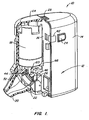
Fig. 1 illustrates a partial cutaway view of an exemplary apparatus having an aerosol generator for aerosolizing liquids according to the invention. -
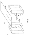
Fig. 2 is a schematic diagram of an inhalation flow sensor for detecting when a patient begins to inhale from an aerosolizing apparatus according to the invention. -
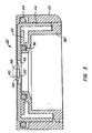
Fig. 3 is a cross-sectional side view of an aerosol generator of the aerosolizing apparatus ofFig. 1 . -
Fig. 4-9 illustrate cross-sectional side views of a container and a piston pump used in the apparatus ofFig. 1 to deliver a predetermined volume of liquid to the aerosol generator. The views illustrated inFigs. 4-9 show various states of the piston pump when metering and transferring liquids from the container to the aerosol generator. -
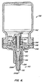
Fig. 10 is a schematic view of an aerosolizing system having a removable cartridge holding a substance that is in a solid state according to the invention. -
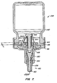
Fig. 11 illustrates the aerosolizing system ofFig. 10 having the cartridge removed for cleaning of the aerosol generator according to the invention. -
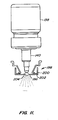
Fig. 12 is a cross sectional side view of an alternative apparatus for aerosolizing a solution according to the invention. -
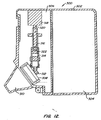
Fig. 13 illustrates a dual chamber drug cartridge and an aerosol generator of the apparatus ofFig. 12 . -
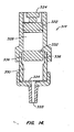
Figs. 14-17 illustrate the drug cartridge ofFig. 13 in various states of operation to dispense a solution onto the aerosol generator according to the invention. -
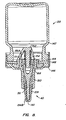
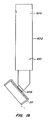
Fig. 18 illustrates the apparatus ofFig. 1 with an alternative cartridge to deliver liquids to the aerosol generator according to the invention. -
Fig. 19 illustrates the cartridge and aerosol generator ofFig. 18 . -
Fig. 20 is a cross-sectional view of the cartridge ofFig. 19 . -
Fig. 21 is a more detailed view of the cartridge ofFig. 19 . -
Fig. 22 is a cross-sectional side view of a dispensing system having a drug cartridge and a piston pump according to the invention. - The invention provides exemplary systems, apparatus and methods for reconstituting a solid substance that is in a dry state with liquid, such as water, to form a solution and for transporting the solution to an aerosol generator for subsequent atomization. In one exemplary embodiment, the system comprises a liquid dispenser, a cartridge containing the substance that is in the dry state, and an aerosol generator. In use, the cartridge is coupled to an outlet of the dispenser. The user then actuates the liquid dispenser so that liquid is dispensed from the dispenser and enters into the cartridge. As the liquid flows through the cartridge, the dry substance is dissolved into the liquid and exits the cartridge as a solution. Preferably, the cartridge is replaced and disposed after each use. In a preferred embodiment, an outlet end of the cartridge is positioned near the aerosol generator so that the solution disposed on the aerosol generator is readily available for atomization.
- In one alternative, a two step process is employed to reconstitute the solution and deliver the solution to the aerosol generator. First, a portion of a unit volume of liquid, such as one-half a unit volume, is supplied to the cartridge when the liquid dispenser is operated. The user then waits a predetermined amount of time, such as about 10 seconds, and again operates the liquid dispenser to deliver sufficient liquid into the cartridge to force a unit volume of solution from the cartridge an onto the aerosol generator. In this way, a period of time is provided to allow more of the substance to dissolve in the liquid.
- In another aspect of the invention, exemplary systems and methods are provided for metering relatively small volumes of liquid directly from a container and for delivering the metered volume to an atomizer. The systems and methods are configured to precisely meter and deliver relatively small volumes of liquid, typically in the range from about 10 µL to about 100 µL. When delivering volumes in the range from about 10 µL to 50 µL, the invention preferably employs the use of a piston pump that is connected to a canister as described in greater detail hereinafter. For volumes in the range from about 50 µL to about 100 µL, a pharmaceutical pump is preferably employed, such as metered dose S4 pump, commercially available from Somova S. p.A. Milano, Italy. Optionally, such pharmaceutical pumps may also contain a pharmaceutical medicament which may be delivered directly to the aerosol generator. As one example, the pharmaceutical medicament may comprise a suspension of colica steroid for treatment of asthma.
- Another feature of the liquid dispensers of the invention is that they are configured to prevent or substantially reduce the possibility of contamination. In this way, each subsequent dosage delivered by the liquid dispenser is not contaminated when delivered to the atomizer. Referring now to
Fig 1 , anexemplary apparatus 10 for atomizing a liquid will be described.Apparatus 10 comprises ahousing 12 which is configured to hold the various components ofapparatus 10.Housing 12 is preferably constructed to be lightweight and pocket-sized, typically being molded of a plastic material.Housing 12 is divided into two separable portions. Afirst portion 14 includes an electronics compartment and asecond portion 16 includes a liquid holding compartment for holding acanister 18, anaerosol generator 22, and amouthpiece 20 through which the atomized liquids are dispensed to the patient. Conveniently, second portion can be separated fromfirst portion 14 by sliding aknob 23. Optionally,second portion 16 having the liquid holding component may be disposed following separation fromfirst portion 14.Second portion 16 may be disposed along withcanister 18, orcanister 18 may be disposed separately. -
Apparatus 10 further includes aninhalation flow sensor 24 which detects the inhalation flow produced by the patient when inhaling frommouthpiece 22. Upon detection of the inhalation,sensor 24 sends an electrical signal to an electronic circuit (not shown) which in turn sends an alternating voltage to vibrate apiezoelectric member 26 ofaerosol generator 22 to aerosolize a liquid.Sensor 24 preferably comprises a flexure foil and an electro-optical sensor. The flexible foil deflects in response to the inhalation airflow produced when a patient inhales frommouthpiece 20. The optical sensor is configured to detect deflection of the flexible foil so that a signal may be produced to vibratepiezoelectric member 26. - Referring now to
Fig. 2 , a schematic diagram of aninhalation flow sensor 24 will be described.Flow sensor 24 comprises aflexible foil 28 having anextension 30.Inhalation flow sensor 24 further includes anoptical sensor 32 which includes a light emitting diode (LED) 34 and a lightsensitive transistor 36 placed in apposition to LED 34 so that LED 34 continuously transmits alight beam 38 totransistor 36. When the patient inhales, the inhalation airflow causesflexible foil 28 to deflect and moveextension 30 downward until it crosseslight beam 38 and causes an optical interruption that is detected bytransistor 36.Transistor 36 then sends a signal to trigger activation of an aerosol generator to produce an aerosol. - By configuring
inhalation flow sensor 24 in this manner,aerosol generator 22 is actuated only in response to the detection of an inhalation airflow produced by a patient. In this way, the patient may be administered a single dose using either a single inhalation or multiple inhalations. Preferably,inhalation flow sensor 24 is triggered at an inhalation flow rate of at least 15 liters per minute. However, it will be appreciated thatsensor 24 may be constructed to trigger at either lower or higher flow rates. Adjustment of the actuation point may be accomplished by altering the flexible stiffness offoil 28, by selecting different materials for constructingfoil 28 or by changing the thickness offoil 28. - Alternatively, the inhalation flow sensor may be constructed from a piezoelectric film component. The piezoelectric film component produces an electrical signal when it deflects. The magnitude of the electrical signal is proportional to the magnitude of deflection. In this way, the electrical signal that is produced by the piezoelectric film component can be used to detect the magnitude of the inhalation flow. In this manner, the output of the aerosol generator may be adjusted in proportion to the inhalation airflow. Such a proportional output from the aerosol generator is particularly advantageous in that it prevents the coalescence of particles and controls the aerosol production according to the inhalation flow. Control of the aerosol output may be adjusted by turning the aerosol generator on and off sequentially. The ratio between the on time and the off time, generally defined as the duty cycle, affects the net flow. An exemplary piezoelectric film component with such characteristics is commercially available from ATO Autochcm Sensors, Inc., Valley Forge, Pennsylvania.
- Referring back to
Fig. 1 , the electronic circuit (not shown) withinfirst portion 14 includes electrical components to detect the presence of liquid onaerosol generator 22 and to send a signal to the user indicating that all of the liquid has been aerosolized. In this way, the user will know if additional inhalations will be required in order to receive the prescribed amount of medicament. The sensing circuit comprises a voltage sensing circuit (not shown) which detects the voltage acrosspiezoelectric element member 26. Since the voltage acrosspiezoelectric member 26 is proportionally related to the amount of liquid in surface tension contact with an aperture plate 40 (seeFig. 3 ) ofaerosol generator 22, it can be determined, based on the voltage, whether any liquid is left remaining. For example, when aerosolization is initiated, the voltage is high. At the end of aerosolization, the voltage is low, thereby indicating that the aerosolization process is near completion. Preferably, the sensing circuit is configured to be triggered when about 95% of the liquid has been aerosolized. When triggered, the sensing circuit turns on a light emitting diode (LED) 42 indicating that the prescribed dosage has been delivered. - Referring now to
Fig. 3 , construction ofaerosol generator 22 will be described in greater detail. As previously described,aerosol generator 22 includes avibratable aperture plate 40 and annularpiezoelectric member 26.Aerosol generator 22 further comprises a cup-shapedmember 44 to whichpiezoelectric member 26 andaperture plate 40 are attached as shown. Cup-shapedmember 44 includes acircular hole 46 over whichaperture plate 40 is disposed. Wires (not shown) connectpiezoelectric member 26 to the electrical circuitry within portion 14 (seeFig. 1 ) which in turn is employed to vibratepiezoelectric member 26. - Cup-shaped
member 44 is preferably constructed of a low damping metal, such as aluminum.Aperture plate 40 is disposed overhole 46 such that arear surface 18 ofaperture plate 40 is disposed to receive liquid from canister 18 (seeFig. 1 ). Although not shown,aperture plate 40 includes a plurality of tapered apertures which taper fromrear surface 48 to afront surface 50. Exemplary aperture plates which may be used with the invention include those described the '740 patent, then '550 patent, and the '637 patent, previously incorporated by reference. -
Aperture plate 40 is preferably constructed of a material that may be produced by a metal electroforming process. As an example,aperture plate 40 may be electroformed from palladium or a palladium alloy, such as palladium cobalt or palladium nickel.Aperture plate 40 may further be gold electroplated to enhance its corrosion resistance or may be constructed of solid gold or gold alloys. Alternatively,aperture plate 40 may be constructed of nickel, a nickel-gold alloy, or a combination of nickel and nickel-gold alloy arranged such that the nickel-gold alloy covers the external surfaces of the aperture plate. The nickel-gold alloy may he formed using a gold electroplating process followed by diffusion at an elevated temperature as described generally in Van Den Belt, TGM, "The diffusion of platinum and gold in nickel measured by Rutherford Fact Scattering Spectrometry", Thin Solid Film, 109 (1983), pp. 1-10. One particular material that may be used to construct the aperture plate comprises about 80% palladium and about 20% nickel, as well as other palladium-nickel alloys as described generally in J.A. Abys, et al., "Annealing Behavior of Palladium-Nickel Alloy Electro Deposits", Plating and Surface Finishing, August 1996. A small amount of manganese may also be introduced to the nickel during the electroforming process so that the nickel can be heat treated at an elevated temperature as described generally inU.S. Patent No. 4,108,740 . The gold-nickel alloy is particularly useful in protecting the nickel components, and particularly the electroformed nickel components, from corrosion caused by plating porosity. The diffusion process may be useful for other applications which require corrosion protection for nickel components, and particularly nickel elcctroformed components, such as, for example, inkjet aperture plates, other spray nozzle plates, and the like. - As another alternative, corrosion resistance of the aperture plate may be enhanced by constructing the aperture plate of a composite electroformed structure having two layers, with the first electroformed layer comprising nickel and the second electroformed layer comprising gold. The thickness of the gold in the composite in preferably at least two microns, and more preferably, at least five microns. Alternatively, the second layer may be electroformed from palladium or another corrosive-resistant metal. The external surfaces of the aperture plate may also be coated with a material that prevents bacteria growth, such as polymyxin or silver. Optionally, other coatings that enhance wetability may be applied to the aperture plate.
- In one embodiment, the aperture plate is protected from corrosive liquids by coating the aperture plate with agents that form a covalent bond with the solid surface via a chemical linking moiety. Such agents are preferred because the are typically biocompatable with acidic pharmaceutical liquids. The agent may be photoreactive, i.e. activated when subjected to light or may be activated when subjected to moisture or to any other means of energy. Further, the agent may have various surface properties, e.g. hydrophobic, hydrophilic, electrically conductive or non-conductive. Still further, more than one agent may be formed on top of each other. Types of coatings that may be included on the aperture plate are described in
U.S. Patent Nos. 4,979,959 ;4,722,906 ;4,826,759 ;4,973,493 ;5,002,582 ;5,073,484 ;5,217,492 ;5,258,041 ;5,263,992 ;5,414,075 ;5,512,329 ;5,714,360 ;5,512,474 ;5,563,056 ;5,637,460 ;5,654,460 ;5,654,162 ;5,707,818 ;5,714,551 ; and5,744,515 . - Cup-shaped
member 44 is disposed within ahousing 52 which prevents liquids from coming into contact withpiezoelectric member 26 and with cup-shapedmember 44. Cup-shapedmember 44 is suspended withinhousing 52 by twoelastic rings Ring 54 is positioned betweenhousing 52 and the circumference of cup-shapedmember 44.Ring 56 is positioned between the inner diameter ofpiezoelectric member 26 and ashield member 58. Such an arrangement provides a hermetic seal that prevents the contact of liquids with thepiezoelectric member 26 without suppressing the vibratory motion of cup-shapedmember 44. - Referring back now to
Fig. 1 ,aerosol generator 22 is axially aligned withmouthpiece 20 so that whenpiezoelectric member 26 is vibrated, liquid droplets are ejected throughmouthpiece 20 and are available for inhalation by the patient. As previously described, disposed withinsecond portion 16 is acanister 18 which holds the liquid medicament to be atomized byaerosol generator 22.Canister 18 is integrally attached to a mechanical pump 60 which is configured to dispense a unit volume of liquid through a nozzle 62 toaerosol generator 22. Pump 60 is actuated by pressing aknob 64 which pushescanister 18 downward to generate the pumping action as described in greater detail hereinafter. Pressing onknob 64 also puts pressure on anelectrical microswitch 66 withinsecond portion 16. When actuated,microswitch 66 sends a signal to the electrical circuit withinfirst portion 14 causing a light emitting diode (LED) (not shown) to blink indicating thatapparatus 10 is ready for use. When the patient begins to inhale, the inhalation is sensed causing actuation of the aerosol generator. - As illustrated in
Fig. 3 , pump 60 delivers a unit volume of liquid 68 (shown in phantom line) torear surface 48 ofaperture plate 40. The deliveredvolume 68 adheres toaperture plate 40 by solid/liquid surface interaction and by surface tension forces until patient inhalation is sensed. At that point,piezoelectric member 26 is actuated to eject liquid droplets fromfront surface 50 where they are inhaled by the patient. By providing the delivered volume 60 in a unit volume amount, a precise dose of liquid medicament may be atomized and delivered to the lungs of the patient. Althoughcanister 18 ofFig. 1 is shown as being configured to directly deliver the dispensed liquid to the aperture plate, pump 60 may alternatively be configured to receive a cartridge containing a chemical in a dry state as described in greater detail hereinafter. - Referring now to
Figs. 4-10 , a schematic representation of acanister 138 and apiston pump 140 will be described to illustrate an exemplary method for dispensing a unit volume of a liquid medicament to an aperture plate, such asaperture plate 40 of apparatus 10 (seeFigs. 1 and3 ).Canister 138 comprises ahousing 142 having anopen end 144 about which acap 146 is placed. Disposed againstopen end 144 is awasher 148 which provides a seal to prevent liquids from escaping fromhousing 142. On top ofwasher 148 is acylindrical member 150.Cap 146 securely holdscylindrical member 150 andwasher 148 tohousing 142.Cylindrical member 150 includes acylindrical opening 151 which allows liquids to enter fromcanister 138.Cylindrical member 150 in combination withwasher 148 also serve to securely position a holdingmember 152 about which acompression spring 154 is disposed. -
Piston pump 140 comprises apiston member 156,cylindrical member 150, avalve seat 158 andcompression spring 154.Piston member 156 has afrontal end 156A and adistal end 156B, withfrontal end 156A providing the piston action anddistal end 156B providing the valve action. -
Piston pump 140 is configured such that everytime valve seat 158 is depressed towardcanister 138 and then released, a unit volume of liquid is dispensed through atapered opening 161 invalve seat 158.Valve scat 158 includes avalve seat shoulder 158A which is pressed to move valve seat inwardly, causingvalve seat 158 to engage withdistal end 156B to close taperedopening 161. - As shown in
Fig. 5 , aspiston member 156 is further depressed intocylindrical member 150,spring 154 is compressed and ametering chamber 168 begins to form betweenfrontal end 156A andcylindrical member 150.Frontal end 156A anddistal end 156B are preferably constructed from a soft elastic material which provides a hermetic seal withcylindrical member 150 andvalve seat 158, respectively. Due to the seal betweenfrontal end 156A andcylindrical member 150, a vacuum is created withinmetering chamber 168 upon depression ofpiston member 156. - As
piston member 156 is further moved into cylindrical member 150 (seeFig. 6 ),spring 154 is further compressed andfrontal end 156A moves pastcylindrical opening 151 so that a gap is provided betweenfrontal end 156A andcylindrical member 150. Asfrontal end 156A passes the edge ofcylindrical member 150, liquid fromcanister 138 is drawn intocylindrical member 150 by the vacuum that was created withinmetering chamber 168. InFig. 6 ,piston member 156 is in the filling position. - At the end of inward travel, the user releases the pressure on
valve seat 158, allowingspring 154 to pushpiston member 156 back toward its starting position. As illustrated inFig. 7 , upon the return travel ofpiston member 156 to the starting position,frontal end 156A again engagescylindrical member 150 and forms a seal between the two surfaces to prevent any liquid withinmetering chamber 168 from flowing back intocanister 138. - Since the liquid within
metering chamber 168 is generally incompressible, asspring 154 pushes onpiston member 156, the liquid withinmetering chamber 168forces valve seat 158 to slide distally overpiston member 156. In so doing, the liquid withinmetering chamber 168 is allowed to escape from the metering chamber through taperedopening 161 ofvalve seat 158 as illustrated inFig. 8 . - As illustrated in
Figs. 7-9 , liquid frommetering chamber 168 is dispensed from taperedopening 161 asfrontal end 156A travels length L. Asfrontal end 156A passes through length L, it is in contact withcylindrical member 150. In this way, the liquid withinmetering chamber 168 is forced out of taperedopening 161 during this length of travel. After passing through Length L,frontal end 156A passes out of sealing relationship withcylindrical member 150 so that no further liquid is dispensed from taperedopening 161. Hence, the amount of liquid dispensed is proportional to the diameter ofcylindrical member 150 over length L. As such,piston pump 140 may be designed to dispense a known volume of liquid eachtime piston member 156 travels from the starting position to the filling position and then back to the starting position. Sincepiston member 156 must be fully depressed to the filling position in order to create a gap betweenfrontal end 156A andcylindrical member 150, a way is provided to ensure that partial volumes can not be dispensed. - As shown in
Fig. 9 ,valve seat 158 includes ashoulder 170 which engages astop 172 oncylindrical member 150 to stop distal movement ofvalve seat 158 relative tocylindrical member 150. At this point,piston pump 140 is at an ending dispensing position which corresponds to the starting position as initially illustrated inFig. 4 . In this position,spring 154 forcesdistal end 156B ofpiston member 156 into taperedopening 161 to provide a seal and prevent contaminants from entering intopiston 140. -
Valve seat 158 is preferably coated with a material that inhibits proliferation of bacteria. Such coatings can include, for example, coatings having a positive electric charge, such as polymyxin, polyethylinimin, silver, or the like. - The invention further provides a convenient way to store chemical substances in the solid or dry state and then to dissolve the chemical substance with liquid from the canister to form a solution. In this way, chemical substances that are otherwise susceptible to degradation can be stored in the dry state so that the shelf life of the product is extended. An exemplary embodiment of a cartridge 180 for storing such chemical substances that are in the dry state is illustrated in
Fig. 10 . For convenience of illustration, cartridge 180 will be described in connection withpiston pump 140 andcanister 138, which in turn may be coupled to an aerosolization apparatus, such asapparatus 10, to aerosolize a medicament as previously described. Cartridge 180 comprises acylindrical container 182 having an inlet opening 184 and outlet opening 186.Inlet opening 182 is sized to be coupled to piston pump 140 as shown. Disposed withincontainer 182 is afirst filter 188 and asecond filter 190.Filter 188 is disposed near inlet opening 184 andsecond filter 190 is disposed near outlet opening 186. Achemical substance 192 which is in a dry state is disposed betweenfilters Chemical substance 192 is preferably held within a support structure to increase the rate in which the chemical substance is dissolved. - The support structure may be constructed of a variety of materials which are provided to increase the rate in which the chemical substance is dissolved. For example, the support structure may comprise an open cell material such as a polytetrafluoroethylene (PTFE) matrix material commercially available from Porex Technologies, Farbum, Georgia. Preferably, such an open cell material has a pore size in the range from about 7 µm to about 500 µm, and more preferably about 250 µm. Alternatively, various other plastic materials may be used to construct the open cell matrix, including olyethylene (HDPE), ultra-high molecular weight polyethylene (UHMW), polypropylene (PP), polyvinylidene fluoride (PVDF), nylon 6 (N6), polyethersulfone (PES), ethyl vinyl acetate (EVA), and the like. Alternatively, the support structure may be constructed of a woven synthetic material, a metal screen, a stack of solid glass or plastic beads, and the like.
- An exemplary method for placing
chemical substance 192 intocontainer 182 is by fillingcontainer 182 with the chemical substance while the chemical substance is in a liquid state and then lyophilizing the substance to a dry state while the substance within the cartridge. In this way, filling of cartridge 180 with a chemical substance may be precisely and repeatedly controlled. However, it will be appreciated that the chemical substance may be placed into cartridge 180 when in the solid state. - Lyophilization is one exemplary process because it will tend to reduce the rate of various physical and chemical degradation pathways. If the substance comprises a protein or peptide, both the lyophilization cycle (and resulting moisture content) and product formulation can be optimized during product development to stabilize the protein before freezing, drying and for long term storage. See Freeze Drying of Proteins, M.J. Pikal, BioPharm. 3, 18-26 (1990); Moisture Induced Aggregation of Lyophilized Proteins in the Solid State, W.R. Liu, R. Langer, A.M. Klibanov, Biotech. Bioeng. 37, 177-184 (1991); Freeze Drying of Proteins. II, M.J. Pikal, BioPharm. 3, 26-30 (1990); Dehydration Induced Conformational Transitions in Proteins and Their Inhibition by Stabilizers, S.J. Prestrelski, N. Tedeschi, S. Arakawa, and J.F. Carpenter, Biophys. J. 65, 661-671 (1993); and Separation of Freezing and Drying Induced Denaturation of Lyophilized Proteins Using Stress-Specific Stabilization, J.F. Carpenter, S.J.Prestrelski, and T. Arakawa, Arch. Biochem. Biphys. 303, 456-464 (1993). Adjustment of the formulation pH and/or addition of a wide variety of additives including sugars, polysaccharides, polyoles, amino-acids, methylamines, certain salts, as well as other additives, have been shown to stabilize protein towards lyophilization.
- As an example, which is not meant to be limiting, a cartridge was packed with small glass beads having a diameter of approximately 0.5 mm. The cartridge was filed with a solution of lysozyme at a concentration of 10 mg/ml. To enhance its stability, the solution was combined with a form of sugar and with a buffer solution. The buffer solution was sodium citrate, and the sugar was mannitol. A twin 20 surfactant was also added to the solution. The solution was then lyophilized in the cartridge.
- The lyophilized substance may optionally contain a solubility enhancer, such as a surfactant as described in Journal of Pharmaceutical Science Technology which is J.Pharmsei. Technology, 48; 30-37 (1994). To assist in protecting the chemical substance from destructive reactions while in the dry state, various sugars may be added as described in Crowe, et al., "Stabilization of Dry Phospholipid Bilayer and Proteins by Sugars", Bichem. J. 242: 1-10 (1987), and Carpenter, et al. "Stabilization of Phosphofructokinase with Sugars Drying Freeze-Drying", Biochemica. et Biophysica Acta 923: 109-115 (1987).
- In use, cartridge 180 is coupled to
piston pump 140 andpiston pump 140 is operated as previously described to dispense a known volume of liquid into cartridge 180. The supplied liquid flows throughchemical substance 192 andchemical substance 192 dissolves into the liquid and flows out of outlet opening 186 as aliquid solution 194. Outlet opening 186 is spaced apart from anaperture plate 196 of anaerosol generator 198 so thatliquid solution 198 will be deposited onaperture plate 196 as shown.Aerosol generator 198 further includes a cup shapednumber 200 and apiezoelectric member 202 and operates in a manner similar to theaerosol generator 22 as previously described. Hence, whenaerosol generator 198 is operated,liquid solution 194 is ejected fromaperture plate 196 in droplet form as shown. - One important feature of the invention is that cartridge 180 is removable from
piston pump 140 so that cartridge 180 may be discarded following each use. As illustrated inFig. 11 , after cartridge 180 has been removed, the user may optionally actuatepiston pump 140 to again deliver a volume ofliquid 204 directly to aperture plate 96.Aerosol generator 198 is then operated so that, similar to an ultrasonic cleaner, the vibratory action removes any residual solution fromaperture plate 196. Liquids that may be held withincanister 138 to form the solution and to cleanaperture plate 196 include sterile water, a mixture of water with ethanol or other disinfectant, and the like. - In summary, the invention provides a portable aerosolizing apparatus that is able to store a chemical substance in the dry state, and to reconstitute the chemical substance with liquid to form a solution just prior to administration. The invention further provides techniques for aerosolizing the solution and for cleaning the aerosol generator. Also, it will be appreciated that the aerosolization apparatus as described herein may be used to aerosolize a liquid medicament that is not stored within a cartridge so that the liquid medicament is passed directly from the piston pump and on to the aperture plate for aerosolization.
-
Apparatus 10 may optionally be configured to warn the user when cleaning is needed. Such a feature is best accomplished by providing a processor withinsecond portion 14 which is programmed to include an expected amount of time required to aerosolize a dose received fromcanister 18. If the expected amount of time exceeded before the entire dose is aerosolized, it may be assumed that the apertures in the aperture plate are clogged, thereby requiring cleaning to clear the apertures. In such an event, the processor sends a signal to an LED onapparatus 10 indicating that cleaning is needed. - To determine whether all of the liquid has been aerosolized in the expected time period, the processor records the amount of time that the aerosol generator is actuated. When the aerosol generator has been actuated for the expected time, the voltage sensing circuit is actuated to detect whether any liquid remains on the aperture plate as previously described.
- Referring now to
Fig. 12 , an alternative embodiment of anapparatus 300 for atomizing a liquid solution will be described.Apparatus 300 includes ahousing 302 that is divided into two separable portions similar to the embodiment ofFig. 1 . Afirst portion 304 includes various electronics and asecond portion 306 includes a liquid holding compartment. Anaerosol generator 308 which is similar toaerosol generator 22 ofFig. 1 is disposed insecond portion 306 to aerosolize a solution where it will be available for inhalation through amouthpiece 310. Conveniently,aerosol generator 308 includes alip 312 to catch the solution and maintain it in contact with theaerosol generator 308 until acrosolized. Disposed aboveaerosol generator 308 is adrug cartridge 314. As will be described in greater detail hereinafter,cartridge 314 is employed to produce a solution which is delivered toaerosol generator 308 for aerosolization. - Coupled to
cartridge 314 is alead screw 316. In turn,lead screw 316 is coupled to amicro-coreless DC motor 318. Whenmotor 318 is actuated, it causes ashaft 320 to rotate. This rotational motion is converted to linear motion bylead screw 316 to translate apiston 322 withincartridge 314 as described in greater detail hereinafter.Motor 318 is actuated by appropriate electronics held infirst portion 304. Further, a power source, such as a battery, is also held withinfirst portion 304 to supply power tomotor 318.Aerosol generator 38 is operated in a manner essentially identical to that previously described in connection with the apparatus ofFig. 1 . - Referring now to
Fig. 13 , construction ofcartridge 314 will be described in greater detail.Piston 322 includes adocking knob 324 which mates with aconnector 326 oflead screw 316.Docking knob 324 andconnector 326 are configured to facilitate easy coupling and uncoupling. Typically,motor 318 andlead screw 316 are securely coupled to housing 308 (seeFig. 12 ), whilecartridge 314 is configured to be removable fromhousing 302. In this way, each time a new drug cartridge is required, it may be easily inserted intoapparatus 300 and coupled withlead screw 316. -
Lead screw 316 is configured such that whenmotor 318 causesshaft 320 to rotate in a clockwise direction,lead screw 316 is moved downward. Alternatively, whenmotor 318 is reversed,lead screw 316 is moved upward. In this way,piston 322 may be translated back and forth withincartridge 314.Motor 318 is preferably calibrated such thatpiston 322 can be moved to selected positions withincartridge 314 as described in greater detail hereinafter. -
Cartridge 314 includes afirst chamber 328 and asecond chamber 330. Although not shown for convenience of illustration,first chamber 328 is filled with a liquid andsecond chamber 330 includes a substance that is in a dry state. Such a substance preferably comprises a lyophilized drug, although other substances may be employed similar to the embodiment ofFig. 1 . Separatingfirst chamber 328 andsecond chamber 330 is adivider 332. As shown inFig. 13 ,divider 332 is in a home position which forms a seal betweendivider 332 andcartridge 314 so that the liquid is maintained withinfirst chamber 328 untildivider 332 is moved from its home position as described hereinafter. -
Cartridge 314 includes anexit opening 333 which is disposed in close proximity toaerosol generator 308. Once the solution is formed withincartridge 314, it is dispensed throughexit opening 333 and on toaerosol generator 308 where it will be aerosolized for delivery to the patient. Disposed across exit opening 333 is afilter 334 which serves to prevent larger drug particles from being flushed out ontoaerosol generator 308, thus causing potential clogging of the apertures withinaerosol generator 308. - Referring now to
Figs. 14-17 , operation ofcartridge 314 to produce a solution which is delivered toaerosol generator 308 will be described.Cartridge 314 is constructed in a manner similar to the drug cartridge described inU.S. Patent No. 4,226,236 . As shown inFig. 14 ,cartridge 314 is in the home position wheredivider 332 maintains the liquid withinfirst chamber 328. When in the home position,cartridge 314 may be inserted intoapparatus 300 and coupled to lead screw 316 (seeFig. 13 ). When ready to deliver an aerosolized solution to a patient, motor 318 (seeFig. 13 ) is actuated to causelead screw 316 to translatepiston 322 withincartridge 314 as illustrated inFig. 15 . Aspiston 322 is translated withincartridge 314, it begins to move throughfirst chamber 328. Since the liquid is generally incompressible, the liquid will forcedivider 332 to move in the direction ofsecond chamber 330. Formed in the walls ofcartridge 314 are one ormore grooves 336 which are placed in communication withfirst chamber 328 asdivider 332 moves away from its home position. As such, the liquid withinfirst chamber 328 is forced intochamber 330 as illustrated by the arrows. Once the liquid is able to flow arounddivider 332, the pressure acting against it is relieved so that it remains in the position generally shown inFig. 15 . As the liquid enters intosecond chamber 330, the lyophilized drug is dissolved into the liquid to form a solution. - As illustrate in
Fig. 16 ,piston 322 is translated until it engagesdivider 332. At this point, all of the liquid has been transferred fromfirst chamber 328 intosecond chamber 330. At this point, it may optionally be desired to mix the solution that has just been formed withinsecond chamber 330. This may be accomplished by translatingpiston 322 backward toward the position illustrated inFig. 15 . In so doing, a vacuum is created withinfirst chamber 328 to draw the solution fromsecond chamber 330 intofirst chamber 328. As the solution flows throughgrooves 336, the solution is agitated, causing mixing.Piston 322 may then be translated back to the position shown inFig. 16 to move the liquid back intosecond chamber 330. This process may be repeated as many times as needed until sufficient mixing has occurred. - After proper mixing, the solution is ready to be dispensed onto the aerosol generator. To do so,
piston 332 is moved throughsecond chamber 330 as illustrated inFig.17 . In turn,divider 332 is pushed againstfilter 334 to completely closesecond chamber 330 and force all of the liquid outexit opening 333. - One particular advantage of
cartridge 314 is that a precise volume of drug is dispensed ontoaerosol generator 308 to ensure that the patient will receive the proper dosage. Further, by maintaining the drug in the dry state, the shelf life may be increased as previously described. - Following dispensing of the solution,
cartridge 314 may be removed and replaced with another replacement drug cartridge. Optionally, a cleaning cartridge may he inserted intoapparatus 300 which includes a cleaning solution. This cleaning solution is dispensed ontoaerosol generator 308 upon operation ofmotor 318.Aerosol generator 308 may then be operated to clean its apertures using the cleaning solution. - Referring now to
Fig. 18 , an alternative apparatus 400 for atomizing a liquid will be described. Apparatus 400 is essentially identical toapparatus 10 except thatcanister 18 has been replaced with acontinuous feed cartridge 402.Cartridge 402 is configured to continuously feed liquid toaerosol generator 22 on demand so that enough liquid will always be available eachtime aerosol generator 22 is actuated.Cartridge 402 also ensures that excessive liquid will not be supplied, i.e. it will supply only as much liquid as is atomized.Cartridge 402 is constructed similar to the cartridges described in co-pendingU.S. Patent Application Serial No. 08/471,311, filed April 5, 1995 - As illustrated in
Figs. 19-21 ,cartridge 402 comprises aliquid reservoir 404 and aface 406 which is adjacent the aperture plate ofaerosol generator 22 to supply liquid fromliquid reservoir 404 to the aperture plate. Acapillary pathway 408 extends betweenreservoir 404 and face 406 to supply liquid to face 406 by capillary action. In order to overcome the vacuum that is produced inreservoir 404, a ventingchannel 410 is in communication withpathway 408. In this way, air is able to enter intoreservoir 404 to reduce the vacuum and allow additional liquid to be transferred fromreservoir 404. - In another embodiment, a drug cartridge may be coupled to a piston pump to form a dispensing system that is used to supply a formulation to an aerosol generator. For example, as shown in
Fig. 22 adispensing system 430 comprises acartridge 432 and apiston pump 434.Cartridge 432 is patterned aftercartridge 314 ofFig. 14 and includes afirst chamber 436 and asecond chamber 438. Disposed inchamber 436 is a liquid (not shown) and disposed insecond chamber 438 is a driedsubstance 440. Adivider 442 separates the chambers. In use, aplunger 444 is moved throughchamber 436 to forcedivider 442 forward and to allow the liquid to enterchamber 438 and form a solution. -
Piston pump 434 may be constructed similar to pump 138 ofFig. 4 .Pump 434 is operated to dispense a volume of the solution from chamber438. Pump 434 may be disposed near an aerosol generator so that a volume of the solution will be available for atomization. In this way, known volumes of a solution that was formed from a direct substance may be provided in an easy and convenient manner. - There is also described herein a method for aerosolizing a substance, the method comprising transferring a liquid from a first chamber into a second chamber having a substance in a dry state to form a solution, transferring the solution from the second chamber onto an atomization member; and operating the atomization member to aerosolize the solution.
- Aerosolizing apparatus is also described herein, the apparatus comprising a cartridge having a first chamber, a second chamber, a movable divider between the first and the second chambers, and an exit opening in communication with the second chamber, wherein a liquid is disposed in the first chamber and a substance that is in a dry state is in the second chamber, a piston translatable within the cartridge to transfer the liquid from the first chamber and into the second chamber to form a solution and an aerosol generator disposed near the exit opening to receive the solution from the cartridge and produce an aerosolized solution.
- Also described is an apparatus to make a predetermined volume of liquid available for subsequent atomization, the apparatus comprising a container adapted to hold a reservoir of liquid, a piston pump comprising a piston member and a cylindrical member, wherein the piston member is slidable within the cylindrical member, and wherein the cylindrical member defines a metering chamber, wherein the metering chamber is adapted to be filled with liquid from the reservoir when the piston member is moved to a filling position, and wherein the piston pump is adapted to dispense a known volume of the liquid from the metering chamber when the piston member is moved to a dispensing position.
- There is also described herein an apparatus for nebulizing a liquid, the apparatus comprising: a housing, a vibratable member disposed within the housing, the vibratable member comprising a front surface, a rear surface, and a plurality of apertures extending therebetween, a liquid supplier disposed within the housing which is adapted to deliver a predetermined volume of liquid to the rear surface and a vibrator which vibrates the vibratable member to eject liquid droplets from the front surface of the vibratable member, wherein the liquid supplier comprises a container adapted to hold a reservoir of liquid, and a piston pump comprising a piston member and a cylindrical member which defines a metering chamber, wherein the metering chamber is adapted to be filled with liquid from the reservoir when the piston member is moved within the cylindrical member to a filling position, and wherein the piston pump is adapted to dispense a known volume of the liquid from the metering chamber when the piston member is moved to a dispensing position.
- A method to make a predetermined volume of liquid available for atomization is also described, the method comprising drawing liquid from a container into a metering chamber with a vacuum to fill the metering chamber with liquid and dispensing a known volume of the liquid from the metering chamber such that a known volume of the liquid is available for atomization.
- The invention has now been described in detail, however, it will appreciated that certain changes and modifications may be made. Therefore, the scope and content of this invention are not limited by the foregoing description. Rather the scope and content are to be defined by the following claims.
Claims (6)
- An aerosolizing system, comprising:an aerosol generator (22) including a housing (52), a cup-shaped member (44), a shield member (58), an aperture plate (40) having a plurality of holes therein and an annular piezoelectric member (26) for vibrating the aperture plate, the piezoelectric member being connectable to electrical circuitry to vibrate the piezoelectric member, wherein the aperture plate and the piezoelectric member are attached to the cup-shaped member, the aperture plate being disposed over a hole in the cup-shaped member, and the cup-shaped member being suspended within the housing by a first elastic ring (54) positioned between the housing and the cup-shaped member and by a second elastic ring (56) positioned between the piezoelectric member and the shield member;means for supplying a liquid to be aerosolized to the aperture plate, wherein the liquid is aerosolized when the aperture plate is vibrated; andan electronic sensing circuit with electrical components to detect the presence of liquid on the aperture plate by sensing a voltage across the piezoelectric member, the voltage being indicative of the amount of liquid remaining on the aperture plate, and to send a signal that indicates when all of the liquid has been aerosolized.
- The aerosolizing system of claim 1 or 2, wherein the sensing circuit is configured to be triggered when about 95% of the liquid has been aerosolized.
- The aerosolizing system of claim 1, or 2, further comprising a light emitting diode that is turned on to indicate that a prescribed dosage has been delivered.
- A method for aerosolizing a liquid with the aerosolizing system according to any of claims 1-3, the method comprising:supplying the liquid to the aperture plate (40);exciting the piezoelectric member (26) coupled to the aperture plate such that the aperture plate vibrates, aerosolizing the liquid;sensing the amount of liquid remaining on the aperture plate by sensing a voltage across the piezoelectric member, the voltage being indicative of the amount of liquid remaining on the aperture plate; andgenerating a signal when substantially all of the liquid on the aperture plate has been aerosolized;wherein the aerosolized liquid is not delivered to a human or animal body.
- The method of claim 4, further comprising triggering the sensing circuit when about 95% of the liquid on the aperture plate has been aerosolized.
- The method of claim 4 or 5, further comprising turning on a light emitting diode to indicate that a prescribed dosage has been delivered.
Applications Claiming Priority (5)
| Application Number | Priority Date | Filing Date | Title |
|---|---|---|---|
| US09/095,737 US6014970A (en) | 1998-06-11 | 1998-06-11 | Methods and apparatus for storing chemical compounds in a portable inhaler |
| US09/149,426 US6205999B1 (en) | 1995-04-05 | 1998-09-08 | Methods and apparatus for storing chemical compounds in a portable inhaler |
| US09/313,914 US6755189B2 (en) | 1995-04-05 | 1999-05-18 | Methods and apparatus for storing chemical compounds in a portable inhaler |
| EP05020405A EP1632210B1 (en) | 1998-06-11 | 1999-06-10 | Aerosol generator with vibratable plate |
| EP99928560A EP1009363B1 (en) | 1998-06-11 | 1999-06-10 | Apparatus for nebulising a liquid in a portable inhaler |
Related Parent Applications (4)
| Application Number | Title | Priority Date | Filing Date |
|---|---|---|---|
| EP05020405 Previously-Filed-Application | 1999-06-10 | ||
| EP99928560.4 Division | 1999-06-10 | ||
| EP99928560A Division EP1009363B1 (en) | 1998-06-11 | 1999-06-10 | Apparatus for nebulising a liquid in a portable inhaler |
| EP05020405.6 Division | 2005-09-19 |
Publications (2)
| Publication Number | Publication Date |
|---|---|
| EP2149359A1 EP2149359A1 (en) | 2010-02-03 |
| EP2149359B1 true EP2149359B1 (en) | 2013-01-30 |
Family
ID=27377984
Family Applications (3)
| Application Number | Title | Priority Date | Filing Date |
|---|---|---|---|
| EP05020405A Expired - Lifetime EP1632210B1 (en) | 1998-06-11 | 1999-06-10 | Aerosol generator with vibratable plate |
| EP09176963A Expired - Lifetime EP2149359B1 (en) | 1998-06-11 | 1999-06-10 | Aerosolising system with vibratable plate |
| EP99928560A Expired - Lifetime EP1009363B1 (en) | 1998-06-11 | 1999-06-10 | Apparatus for nebulising a liquid in a portable inhaler |
Family Applications Before (1)
| Application Number | Title | Priority Date | Filing Date |
|---|---|---|---|
| EP05020405A Expired - Lifetime EP1632210B1 (en) | 1998-06-11 | 1999-06-10 | Aerosol generator with vibratable plate |
Family Applications After (1)
| Application Number | Title | Priority Date | Filing Date |
|---|---|---|---|
| EP99928560A Expired - Lifetime EP1009363B1 (en) | 1998-06-11 | 1999-06-10 | Apparatus for nebulising a liquid in a portable inhaler |
Country Status (14)
| Country | Link |
|---|---|
| US (3) | US6205999B1 (en) |
| EP (3) | EP1632210B1 (en) |
| JP (2) | JP2002529114A (en) |
| CN (1) | CN1303309A (en) |
| AT (2) | ATE304833T1 (en) |
| AU (1) | AU4560399A (en) |
| BR (1) | BR9906489A (en) |
| CA (1) | CA2300975C (en) |
| DE (2) | DE69927340T2 (en) |
| ES (3) | ES2401847T3 (en) |
| HK (1) | HK1091394A1 (en) |
| MX (1) | MXPA00001489A (en) |
| NZ (1) | NZ502308A (en) |
| WO (1) | WO1999063946A2 (en) |
Families Citing this family (154)
| Publication number | Priority date | Publication date | Assignee | Title |
|---|---|---|---|---|
| US6540154B1 (en) * | 1991-04-24 | 2003-04-01 | Aerogen, Inc. | Systems and methods for controlling fluid feed to an aerosol generator |
| US6782886B2 (en) | 1995-04-05 | 2004-08-31 | Aerogen, Inc. | Metering pumps for an aerosolizer |
| US6427682B1 (en) * | 1995-04-05 | 2002-08-06 | Aerogen, Inc. | Methods and apparatus for aerosolizing a substance |
| US5758637A (en) | 1995-08-31 | 1998-06-02 | Aerogen, Inc. | Liquid dispensing apparatus and methods |
| US6234167B1 (en) | 1998-10-14 | 2001-05-22 | Chrysalis Technologies, Incorporated | Aerosol generator and methods of making and using an aerosol generator |
| US6235177B1 (en) | 1999-09-09 | 2001-05-22 | Aerogen, Inc. | Method for the construction of an aperture plate for dispensing liquid droplets |
| MY136453A (en) * | 2000-04-27 | 2008-10-31 | Philip Morris Usa Inc | "improved method and apparatus for generating an aerosol" |
| US8336545B2 (en) * | 2000-05-05 | 2012-12-25 | Novartis Pharma Ag | Methods and systems for operating an aerosol generator |
| US6948491B2 (en) * | 2001-03-20 | 2005-09-27 | Aerogen, Inc. | Convertible fluid feed system with comformable reservoir and methods |
| US7600511B2 (en) * | 2001-11-01 | 2009-10-13 | Novartis Pharma Ag | Apparatus and methods for delivery of medicament to a respiratory system |
| US7971588B2 (en) * | 2000-05-05 | 2011-07-05 | Novartis Ag | Methods and systems for operating an aerosol generator |
| US7100600B2 (en) * | 2001-03-20 | 2006-09-05 | Aerogen, Inc. | Fluid filled ampoules and methods for their use in aerosolizers |
| MXPA02010884A (en) | 2000-05-05 | 2003-03-27 | Aerogen Ireland Ltd | Apparatus and methods for the delivery of medicaments to the respiratory system. |
| US7121275B2 (en) * | 2000-12-18 | 2006-10-17 | Xerox Corporation | Method of using focused acoustic waves to deliver a pharmaceutical product |
| US8122880B2 (en) * | 2000-12-18 | 2012-02-28 | Palo Alto Research Center Incorporated | Inhaler that uses focused acoustic waves to deliver a pharmaceutical product |
| US6681998B2 (en) | 2000-12-22 | 2004-01-27 | Chrysalis Technologies Incorporated | Aerosol generator having inductive heater and method of use thereof |
| US6501052B2 (en) | 2000-12-22 | 2002-12-31 | Chrysalis Technologies Incorporated | Aerosol generator having multiple heating zones and methods of use thereof |
| US6701921B2 (en) * | 2000-12-22 | 2004-03-09 | Chrysalis Technologies Incorporated | Aerosol generator having heater in multilayered composite and method of use thereof |
| US7077130B2 (en) * | 2000-12-22 | 2006-07-18 | Chrysalis Technologies Incorporated | Disposable inhaler system |
| US6799572B2 (en) * | 2000-12-22 | 2004-10-05 | Chrysalis Technologies Incorporated | Disposable aerosol generator system and methods for administering the aerosol |
| US6491233B2 (en) | 2000-12-22 | 2002-12-10 | Chrysalis Technologies Incorporated | Vapor driven aerosol generator and method of use thereof |
| US7073499B1 (en) | 2001-02-06 | 2006-07-11 | Injet Digital Aerosols Limited | Inhaler with airflow regulation |
| US6546927B2 (en) | 2001-03-13 | 2003-04-15 | Aerogen, Inc. | Methods and apparatus for controlling piezoelectric vibration |
| US6732944B2 (en) * | 2001-05-02 | 2004-05-11 | Aerogen, Inc. | Base isolated nebulizing device and methods |
| US6554201B2 (en) * | 2001-05-02 | 2003-04-29 | Aerogen, Inc. | Insert molded aerosol generator and methods |
| US6568390B2 (en) | 2001-09-21 | 2003-05-27 | Chrysalis Technologies Incorporated | Dual capillary fluid vaporizing device |
| US6640050B2 (en) | 2001-09-21 | 2003-10-28 | Chrysalis Technologies Incorporated | Fluid vaporizing device having controlled temperature profile heater/capillary tube |
| US6804458B2 (en) * | 2001-12-06 | 2004-10-12 | Chrysalis Technologies Incorporated | Aerosol generator having heater arranged to vaporize fluid in fluid passage between bonded layers of laminate |
| US6681769B2 (en) | 2001-12-06 | 2004-01-27 | Crysalis Technologies Incorporated | Aerosol generator having a multiple path heater arrangement and method of use thereof |
| US6701922B2 (en) | 2001-12-20 | 2004-03-09 | Chrysalis Technologies Incorporated | Mouthpiece entrainment airflow control for aerosol generators |
| US7677467B2 (en) * | 2002-01-07 | 2010-03-16 | Novartis Pharma Ag | Methods and devices for aerosolizing medicament |
| MXPA04006629A (en) | 2002-01-07 | 2004-11-10 | Aerogen Inc | Devices and methods for nebulizing fluids for inhalation. |
| US20050205089A1 (en) * | 2002-01-07 | 2005-09-22 | Aerogen, Inc. | Methods and devices for aerosolizing medicament |
| WO2003059424A1 (en) | 2002-01-15 | 2003-07-24 | Aerogen, Inc. | Methods and systems for operating an aerosol generator |
| GB2384198B (en) | 2002-01-18 | 2005-03-02 | Profile Drug Delivery Ltd | Nebulizer metering |
| US20040063912A1 (en) * | 2002-03-15 | 2004-04-01 | The Brigham And Women's Hospital, Inc. | Central airway administration for systemic delivery of therapeutics |
| WO2003077834A2 (en) * | 2002-03-15 | 2003-09-25 | The Brigham And Women's Hospital, Inc. | Central airway administration for systemic delivery of therapeutics |
| DK1487523T3 (en) * | 2002-03-22 | 2017-08-28 | Clinical Designs Ltd | FIXING FOR A BOX |
| US8245708B2 (en) * | 2002-05-07 | 2012-08-21 | The Research Foundation Of State University Of New York | Methods, devices and formulations for targeted endobronchial therapy |
| US7607436B2 (en) * | 2002-05-06 | 2009-10-27 | The Research Foundation Of State University Of New York | Methods, devices and formulations for targeted endobronchial therapy |
| US6854461B2 (en) * | 2002-05-10 | 2005-02-15 | Philip Morris Usa Inc. | Aerosol generator for drug formulation and methods of generating aerosol |
| EP1509259B1 (en) * | 2002-05-20 | 2016-04-20 | Novartis AG | Apparatus for providing aerosol for medical treatment and methods |
| US20070044792A1 (en) * | 2005-08-30 | 2007-03-01 | Aerogen, Inc. | Aerosol generators with enhanced corrosion resistance |
| US6843430B2 (en) | 2002-05-24 | 2005-01-18 | S. C. Johnson & Son, Inc. | Low leakage liquid atomization device |
| US20040055595A1 (en) * | 2002-09-19 | 2004-03-25 | Noymer Peter D. | Aerosol drug delivery system employing formulation pre-heating |
| US6752327B2 (en) * | 2002-10-16 | 2004-06-22 | S. C. Johnson & Son, Inc. | Atomizer with tilted orifice plate and replacement reservoir for same |
| GB2396825B (en) | 2002-11-20 | 2004-12-08 | Profile Respiratory Systems Lt | Improved inhalation method and apparatus |
| GB2395437C (en) | 2002-11-20 | 2010-10-20 | Profile Respiratory Systems Ltd | Improved inhalation method and apparatus |
| GB0304000D0 (en) * | 2003-02-21 | 2003-03-26 | Clinical Designs Ltd | Dispenser |
| US8616195B2 (en) * | 2003-07-18 | 2013-12-31 | Novartis Ag | Nebuliser for the production of aerosolized medication |
| GB2398065A (en) * | 2003-10-16 | 2004-08-11 | Bespak Plc | Dispensing apparatus |
| GB0327112D0 (en) * | 2003-11-21 | 2003-12-24 | Clincial Designs Ltd | Dispenser and reservoir |
| GB0328859D0 (en) * | 2003-12-12 | 2004-01-14 | Clinical Designs Ltd | Dispenser and counter |
| NZ549588A (en) | 2004-02-24 | 2009-03-31 | Microdose Technologies Inc | Directional flow sensor inhaler |
| US7290541B2 (en) * | 2004-04-20 | 2007-11-06 | Aerogen, Inc. | Aerosol delivery apparatus and method for pressure-assisted breathing systems |
| US7267121B2 (en) * | 2004-04-20 | 2007-09-11 | Aerogen, Inc. | Aerosol delivery apparatus and method for pressure-assisted breathing systems |
| AU2005234774B2 (en) * | 2004-04-20 | 2011-01-20 | Novartis Ag | Aerosol delivery apparatus for pressure assisted breathing |
| US7946291B2 (en) | 2004-04-20 | 2011-05-24 | Novartis Ag | Ventilation systems and methods employing aerosol generators |
| DE602004030544D1 (en) * | 2004-06-09 | 2011-01-27 | Microflow Eng Sa | Improved modular liquid spray system |
| GB0425518D0 (en) | 2004-11-19 | 2004-12-22 | Clinical Designs Ltd | Substance source |
| US7827983B2 (en) * | 2004-12-20 | 2010-11-09 | Hewlett-Packard Development Company, L.P. | Method for making a pharmaceutically active ingredient abuse-prevention device |
| GB0428204D0 (en) | 2004-12-23 | 2005-01-26 | Clinical Designs Ltd | Medicament container |
| JP5059740B2 (en) * | 2005-02-09 | 2012-10-31 | エス3アイ, エル エル シィ | Method and system for detecting, classifying and identifying particles |
| DE102005006375B4 (en) * | 2005-02-11 | 2007-10-11 | Pari GmbH Spezialisten für effektive Inhalation | Aerosol generating device for inhalation therapy devices |
| US20060198941A1 (en) * | 2005-03-04 | 2006-09-07 | Niall Behan | Method of coating a medical appliance utilizing a vibrating mesh nebulizer, a system for coating a medical appliance, and a medical appliance produced by the method |
| US20060198940A1 (en) * | 2005-03-04 | 2006-09-07 | Mcmorrow David | Method of producing particles utilizing a vibrating mesh nebulizer for coating a medical appliance, a system for producing particles, and a medical appliance |
| US20060198942A1 (en) * | 2005-03-04 | 2006-09-07 | O'connor Timothy | System and method for coating a medical appliance utilizing a vibrating mesh nebulizer |
| KR101348594B1 (en) | 2005-05-18 | 2014-01-07 | 노바르티스 아게 | Valves, devices, and methods for endobronchial therapy |
| UA94711C2 (en) * | 2005-05-25 | 2011-06-10 | Аэроджен, Инк. | Vibration systems and methods of making a vibration system, methods of vibrating a plate, aerosol generating system and method of treating a patient |
| WO2007024812A1 (en) * | 2005-08-23 | 2007-03-01 | Aerogen, Inc. | Self-sealing t-piece and valved t-piece |
| GB0518400D0 (en) | 2005-09-09 | 2005-10-19 | Clinical Designs Ltd | Dispenser |
| JP2007130555A (en) * | 2005-11-09 | 2007-05-31 | Tomotaka Koide | Spray device |
| TWM297751U (en) * | 2006-03-21 | 2006-09-21 | Taidoc Technology Corp | Liquid nebulizer |
| TWI308615B (en) * | 2006-06-20 | 2009-04-11 | Ind Tech Res Inst | Micro-pump and micro-pump system |
| DE102006030833A1 (en) * | 2006-07-04 | 2008-01-10 | Pari GmbH Spezialisten für effektive Inhalation | Method and device for cleaning the nebuliser membrane in an inhalation therapy device |
| GB0614621D0 (en) * | 2006-07-24 | 2006-08-30 | 3M Innovative Properties Co | Metered dose dispensers |
| GB0620700D0 (en) * | 2006-10-19 | 2006-11-29 | 3M Innovative Properties Co | Metered dose valves and dispensers |
| FR2908329B1 (en) * | 2006-11-14 | 2011-01-07 | Telemaq | DEVICE AND METHOD FOR ULTRASOUND FLUID DELIVERY |
| US20080110453A1 (en) * | 2006-11-15 | 2008-05-15 | Delphi Technologies Inc. | Nebulizer and methods for controlling the nebulizer |
| US20080110452A1 (en) * | 2006-11-15 | 2008-05-15 | Delphi Technologies Inc. | Nebulizer and method for controlling an amount of liquid that is atomized by the nebulizer |
| US20080156320A1 (en) * | 2007-01-03 | 2008-07-03 | Thomas Low | Ultrasonic nebulizer and method for atomizing liquid |
| JP2008199905A (en) * | 2007-02-16 | 2008-09-04 | Snow Brand Milk Prod Co Ltd | Improving agent for survivability of lactic acid bacterium |
| US20080252793A1 (en) * | 2007-04-12 | 2008-10-16 | Choi Ho-Yeol | Media controller with anti-microbial and anti-fungal capability |
| CA2700534A1 (en) * | 2007-09-25 | 2009-04-02 | Novartis Ag | Treatment of pulmonary disorders with aerosolized medicaments such as vancomycin |
| EP2227259B1 (en) * | 2007-11-26 | 2016-02-17 | S.C. Johnson & Son, Inc. | Volatile material dispensing system |
| JP5383097B2 (en) * | 2008-01-25 | 2014-01-08 | キヤノン株式会社 | Drug discharge device and control method thereof |
| JP5328242B2 (en) * | 2008-07-04 | 2013-10-30 | キヤノン株式会社 | Cleaning device for medicine discharge device |
| US20110171312A1 (en) * | 2008-09-19 | 2011-07-14 | Nektar Therapeutics | Modified therapeutic peptides, methods of their preparation and use |
| EP2898900B1 (en) | 2008-09-19 | 2017-11-15 | Nektar Therapeutics | Polymer conjugates of ziconotide |
| PL2337600T3 (en) | 2008-09-26 | 2020-04-30 | Stamford Devices Limited | Supplemental oxygen delivery system |
| DE102008058725A1 (en) | 2008-11-14 | 2010-05-20 | Ing. Erich Pfeiffer Gmbh | Discharge device for discharging e.g. pharmaceutical liquid, has discharge channels provided with non-parallel adjustment that outwardly deviates from orthogonal direction based on extension of back wall |
| US9453652B2 (en) | 2009-01-09 | 2016-09-27 | S. C. Johnson & Son, Inc. | Fragrance dispenser |
| DE102009010565B3 (en) * | 2009-02-18 | 2010-09-02 | Ing. Erich Pfeiffer Gmbh | discharge |
| GB0904040D0 (en) | 2009-03-10 | 2009-04-22 | Euro Celtique Sa | Counter |
| GB0904059D0 (en) | 2009-03-10 | 2009-04-22 | Euro Celtique Sa | Counter |
| US20130255678A1 (en) * | 2009-07-01 | 2013-10-03 | Microdose Therapeutx, Inc. | Nebulizer for infants and respiratory compromised patients |
| US9060715B2 (en) | 2009-07-22 | 2015-06-23 | Koninklijke Philips N.V. | Nebulizer |
| JP5473532B2 (en) * | 2009-10-23 | 2014-04-16 | 株式会社オプトニクス精密 | Nozzle plate, liquid discharge head and sprayer |
| US9180261B2 (en) * | 2010-01-12 | 2015-11-10 | Dance Biopharm Inc. | Preservative free insulin formulations and systems and methods for aerosolizing |
| US9545488B2 (en) | 2010-01-12 | 2017-01-17 | Dance Biopharm Inc. | Preservative-free single dose inhaler systems |
| US20130269684A1 (en) | 2012-04-16 | 2013-10-17 | Dance Pharmaceuticals, Inc. | Methods and systems for supplying aerosolization devices with liquid medicaments |
| US10842951B2 (en) | 2010-01-12 | 2020-11-24 | Aerami Therapeutics, Inc. | Liquid insulin formulations and methods relating thereto |
| US10857311B2 (en) | 2010-01-12 | 2020-12-08 | Omega Life Science Ltd. | Method and apparatus for producing fine concentrated aerosol |
| EP3501499B1 (en) | 2010-02-11 | 2022-09-07 | Ablynx NV | Methods and compositions for the preparation of aerosols |
| US8578942B2 (en) * | 2010-05-25 | 2013-11-12 | British American Tobacco (Investments) Limited | Aerosol generator |
| DE102010024913A1 (en) | 2010-06-15 | 2011-12-15 | Ing. Erich Pfeiffer Gmbh | A nebulizer |
| US10154923B2 (en) | 2010-07-15 | 2018-12-18 | Eyenovia, Inc. | Drop generating device |
| US8689439B2 (en) | 2010-08-06 | 2014-04-08 | Abbott Laboratories | Method for forming a tube for use with a pump delivery system |
| CA2811947C (en) * | 2010-09-30 | 2019-07-23 | Novartis Ag | Inhaler |
| US9717814B2 (en) | 2010-10-01 | 2017-08-01 | S. C. Johnson & Son, Inc. | Dispensing device |
| US8377000B2 (en) | 2010-10-01 | 2013-02-19 | Abbott Laboratories | Enteral feeding apparatus having a feeding set |
| US8377001B2 (en) | 2010-10-01 | 2013-02-19 | Abbott Laboratories | Feeding set for a peristaltic pump system |
| US9289792B2 (en) | 2010-10-04 | 2016-03-22 | Stamford Devices Limited | Aerosol generator |
| BR112013016671B1 (en) | 2010-12-28 | 2020-12-15 | Stamford Devices Ltd | PLATE WITH NEBULIZING OPENING, VIBRATING MESH OF THE NEBULIZING TYPE AND METHOD FOR THE MANUFACTURING OF THAT PLATE |
| WO2012100205A2 (en) | 2011-01-21 | 2012-07-26 | Biodot, Inc. | Piezoelectric dispenser with a longitudinal transducer and replaceable capillary tube |
| EP3042982A1 (en) * | 2011-12-21 | 2016-07-13 | Stamford Devices Limited | Aerosol generators |
| EP2644282B1 (en) | 2012-03-28 | 2015-10-21 | Tanaka Kikinzoku Kogyo K.K. | Mesh for nebulizer and production method thereof |
| JP5157000B1 (en) * | 2012-03-28 | 2013-03-06 | 田中貴金属工業株式会社 | Nebulizer mesh |
| WO2013186031A2 (en) | 2012-06-11 | 2013-12-19 | Stamford Devices Limited | A method of producing an aperture plate for a nebulizer |
| US20140191063A1 (en) * | 2013-01-08 | 2014-07-10 | Serene House International Enterprise Ltd. | Aromatic nebulizing diffuser |
| EP2968831B1 (en) | 2013-03-15 | 2021-06-23 | Trudell Medical International | Ventilator circuit, adapter for use in ventilator circuit and methods for the use thereof |
| KR102293018B1 (en) | 2013-04-16 | 2021-08-24 | 댄스 바이오팜 아이엔씨. | Liquid dispensing and methods for dispensing liquids |
| EP2910268A1 (en) * | 2014-02-25 | 2015-08-26 | PARI Pharma GmbH | Inhalator and inhalator set |
| WO2015177311A1 (en) | 2014-05-23 | 2015-11-26 | Stamford Devices Limited | A method for producing an aperture plate |
| US10610651B2 (en) | 2014-06-09 | 2020-04-07 | Aerami Therapeutics, Inc. | Self-puncturing liquid drug cartridges and associated dispenser |
| US11273271B2 (en) | 2014-07-01 | 2022-03-15 | Aerami Therapeutics, Inc. | Aerosolization system with flow restrictor and feedback device |
| US10471222B2 (en) | 2014-07-01 | 2019-11-12 | Dance Biopharm Inc. | Aerosolization system with flow restrictor and feedback device |
| US10857313B2 (en) | 2014-07-01 | 2020-12-08 | Aerami Therapeutics, Inc. | Liquid nebulization systems and methods |
| EP3721927A1 (en) | 2014-10-13 | 2020-10-14 | Omega Life Science Ltd | Nebulizers |
| CN104623771B (en) * | 2014-12-16 | 2017-06-16 | 中国人民解放军沈阳军区总医院 | Genomic medicine treats influenza or the quantitative atomising device of the simple dual-purpose portable of lung cancer |
| US20180169713A1 (en) * | 2015-01-23 | 2018-06-21 | Pari Pharma Gmbh | Method for cleaning a membrane of a membrane aerosol generator, which membrane can vibrate, and combination of a cleaning device and a cleaning liquid for such cleaning |
| WO2016137569A1 (en) | 2015-02-25 | 2016-09-01 | Dance Biopharm, Inc. | Liquid insulin formulations and methods relating thereto |
| CN104872820A (en) * | 2015-03-28 | 2015-09-02 | 深圳市杰仕博科技有限公司 | Atomized liquid heating and atomizing device |
| EP4186548A1 (en) | 2015-04-02 | 2023-05-31 | Hill-Rom Services PTE. LTD. | Mask leakage detection for a respiratory device |
| GB201510451D0 (en) * | 2015-06-15 | 2015-07-29 | The Technology Partnership Plc | Actuated-valve metering |
| RU2738578C2 (en) | 2015-07-20 | 2020-12-14 | Перл Терапьютикс, Инк. | Aerosol delivery systems and corresponding methods |
| GB2543065A (en) * | 2015-10-06 | 2017-04-12 | Thorn Security | Smoke detector tester |
| WO2017137252A1 (en) | 2016-02-08 | 2017-08-17 | Koninklijke Philips N.V. | An aerosol generator |
| US20190127447A1 (en) | 2016-05-02 | 2019-05-02 | Ablynx N.V. | Treatment of rsv infection |
| WO2018071425A1 (en) | 2016-10-11 | 2018-04-19 | Microdose Therapeutx, Inc. | Inhaler and methods of use thereof |
| WO2018099968A1 (en) | 2016-11-29 | 2018-06-07 | Ablynx N.V. | Treatment of infection by respiratory syncytial virus (rsv) |
| CN106824607B (en) * | 2017-01-23 | 2018-12-21 | 重庆长安汽车股份有限公司 | A kind of external pressurization voltage-stabilizing system and working method of automobile coating equipment |
| NZ757028A (en) * | 2017-03-20 | 2020-08-28 | Vectura Delivery Devices Ltd | Container for cleaning the membrane of a nebulizer |
| CN110446515B (en) * | 2017-03-20 | 2022-02-18 | 维克多瑞传送设备有限公司 | Method and container for cleaning an atomizer membrane |
| US11413407B2 (en) | 2017-03-23 | 2022-08-16 | Stamford Devices Ltd. | Aerosol delivery device |
| WO2018172561A1 (en) * | 2017-03-23 | 2018-09-27 | Stamford Devices Ltd | Aerosol delivery device |
| TWI615202B (en) * | 2017-04-26 | 2018-02-21 | Quantitative electrospray spray device | |
| KR20240034855A (en) | 2017-06-10 | 2024-03-14 | 아이노비아 인코포레이티드 | Methods and devices for handling a fluid and delivering the fluid to the eye |
| DE102017124742A1 (en) * | 2017-10-23 | 2019-04-25 | Nebu-Tec Med. Produkte Eike Kern Gmbh | Automatic drug dosage in nebulizers |
| CN108392706A (en) * | 2017-12-29 | 2018-08-14 | 合肥美菱净化设备有限公司 | A kind of low frequency ultrasound vaporizer device |
| CN108080203B (en) * | 2018-02-01 | 2023-10-27 | 佛山市顺德区雅洛特电器有限公司 | Ultrasonic atomization essential oil device |
| CN112074316B (en) * | 2018-03-05 | 2022-10-21 | 阿戈斯皮尔医疗公司 | Inhalation and exhalation measurement device for portable inhalation therapy and related methods |
| US11406786B2 (en) | 2019-04-22 | 2022-08-09 | Sunovion Pharmaceuticals Inc. | Nebulizer monitoring device, system and method |
| US20220218926A1 (en) * | 2019-05-07 | 2022-07-14 | Kindeva Drug Delivery L.P. | Inhaler and method of detecting obstruction |
Family Cites Families (176)
| Publication number | Priority date | Publication date | Assignee | Title |
|---|---|---|---|---|
| US2101304A (en) | 1936-06-05 | 1937-12-07 | Sheaffer W A Pen Co | Fountain pen |
| US2187528A (en) | 1937-06-07 | 1940-01-16 | Russell T Wing | Fountain pen |
| US2158615A (en) | 1937-07-26 | 1939-05-16 | Sheaffer W A Pen Co | Fountain pen |
| US2266706A (en) | 1938-08-06 | 1941-12-16 | Stanley L Fox | Nasal atomizing inhaler and dropper |
| NL62585C (en) | 1939-01-06 | |||
| US2292381A (en) | 1940-12-24 | 1942-08-11 | Esterbrook Steel Pen Mfg Co | Fountain pen feed |
| US2283333A (en) | 1941-05-22 | 1942-05-19 | Sheaffer W A Pen Co | Fountain pen |
| US2375770A (en) | 1943-11-19 | 1945-05-15 | Arthur O Dahiberg | Fountain pen |
| US2430023A (en) | 1944-01-27 | 1947-11-04 | Esterbrook Pen Co | Writing implement |
| BE461043A (en) | 1944-04-10 | |||
| US2404063A (en) | 1944-04-27 | 1946-07-16 | Parker Pen Co | Fountain pen |
| US2521657A (en) | 1944-07-07 | 1950-09-05 | Scripto Inc | Fountain pen |
| US2512004A (en) | 1945-03-05 | 1950-06-20 | Russell T Wing | Fountain pen |
| US2474996A (en) | 1945-10-12 | 1949-07-05 | Sheaffer W A Pen Co | Fountain pen |
| NL68028C (en) | 1946-06-08 | |||
| US2779623A (en) | 1954-09-10 | 1957-01-29 | Bernard J Eisenkraft | Electromechanical atomizer |
| US2935970A (en) | 1955-03-23 | 1960-05-10 | Sapphire Products Inc | Fountain pen ink reservoir |
| GB973458A (en) | 1962-10-16 | 1964-10-28 | Exxon Research Engineering Co | Improvements in or relating to methods and apparatus for atomising liquids |
| DE1461628A1 (en) | 1965-04-30 | 1969-03-27 | Montblanc Simplo Gmbh | Ink feed for fountain pen |
| DE1575050A1 (en) | 1966-01-12 | 1972-04-13 | Misto Gen Equipment Co | Ultrasonic fog generator |
| US3738637A (en) | 1968-03-01 | 1973-06-12 | Goldsworthy Eng Inc | Method and apparatus for filament winding about three axes of a mandrel and products produced thereby |
| US3558052A (en) | 1968-10-31 | 1971-01-26 | F I N D Inc | Method and apparatus for spraying electrostatic dry powder |
| US3738574A (en) | 1971-06-15 | 1973-06-12 | Siemens Ag | Apparatus for atomizing fluids with a piezoelectrically stimulated oscillator system |
| NO134730L (en) | 1971-07-19 | 1900-01-01 | ||
| US3983740A (en) | 1971-12-07 | 1976-10-05 | Societe Grenobloise D'etudes Et D'applications Hydrauliques (Sogreah) | Method and apparatus for forming a stream of identical drops at very high speed |
| US3790079A (en) | 1972-06-05 | 1974-02-05 | Rnb Ass Inc | Method and apparatus for generating monodisperse aerosol |
| US3812854A (en) | 1972-10-20 | 1974-05-28 | A Michaels | Ultrasonic nebulizer |
| AT323114B (en) | 1973-05-07 | 1975-06-25 | Voest Ag | PROCEDURE FOR PRILLING |
| US3804329A (en) | 1973-07-27 | 1974-04-16 | J Martner | Ultrasonic generator and atomizer apparatus and method |
| DE2361781A1 (en) | 1973-12-12 | 1975-06-19 | Philips Patentverwaltung | WRITING WORK FOR WRITING WITH LIQUID INK |
| US3958249A (en) | 1974-12-18 | 1976-05-18 | International Business Machines Corporation | Ink jet drop generator |
| US4005435A (en) | 1975-05-15 | 1977-01-25 | Burroughs Corporation | Liquid jet droplet generator |
| DE2537765B2 (en) | 1975-08-25 | 1981-04-09 | Siemens AG, 1000 Berlin und 8000 München | Medical inhalation device for the treatment of diseases of the respiratory tract |
| GB1495910A (en) * | 1975-10-30 | 1977-12-21 | Ibm | Method and bath for electroplating palladium on an articl |
| GB1524748A (en) | 1976-05-28 | 1978-09-13 | Inco Europ Ltd | Production of hard heat-resistant nickel-base electrodeposits |
| DE2703801C3 (en) * | 1977-01-29 | 1979-08-02 | W.C. Heraeus Gmbh, 6450 Hanau | Alloys resistant to glassy melts |
| US4159803A (en) | 1977-03-31 | 1979-07-03 | MistO2 Gen Equipment Company | Chamber for ultrasonic aerosol generation |
| US4268460A (en) | 1977-12-12 | 1981-05-19 | Warner-Lambert Company | Nebulizer |
| DE2811248C3 (en) | 1978-03-15 | 1981-11-26 | Bosch-Siemens Hausgeräte GmbH, 7000 Stuttgart | Liquid atomizer |
| US4338576A (en) | 1978-07-26 | 1982-07-06 | Tdk Electronics Co., Ltd. | Ultrasonic atomizer unit utilizing shielded and grounded elements |
| US4240081A (en) | 1978-10-13 | 1980-12-16 | Dennison Manufacturing Company | Ink jet printing |
| DE2849493C2 (en) | 1978-11-15 | 1982-01-14 | Carl Heyer Gmbh, Inhalationstechnik, 5427 Bad Ems | Hand-held aerosol dispenser |
| DE2854841C2 (en) | 1978-12-19 | 1981-03-26 | Bosch-Siemens Hausgeräte GmbH, 7000 Stuttgart | Liquid atomizer, preferably inhalation device |
| DE2907348A1 (en) | 1979-02-24 | 1980-09-04 | Boehringer Sohn Ingelheim | IMPROVED INHALATION DEVICES |
| US4226236A (en) * | 1979-05-07 | 1980-10-07 | Abbott Laboratories | Prefilled, vented two-compartment syringe |
| DE7917568U1 (en) | 1979-06-19 | 1979-09-20 | Bosch-Siemens Hausgeraete Gmbh, 7000 Stuttgart | INHALATION DEVICE |
| JPS5689569A (en) | 1979-12-19 | 1981-07-20 | Canon Inc | Ink jet recording head |
| DE3010178C2 (en) | 1980-03-17 | 1985-10-03 | Kraftwerk Union AG, 4330 Mülheim | Slotted nozzle equipped with a quick-acting valve to induce pulsed gas flows |
| NL189237C (en) | 1980-04-12 | 1993-02-16 | Battelle Institut E V | DEVICE FOR SPRAYING LIQUIDS. |
| US4336544A (en) | 1980-08-18 | 1982-06-22 | Hewlett-Packard Company | Method and apparatus for drop-on-demand ink jet printing |
| CA1178191A (en) | 1980-10-06 | 1984-11-20 | Naoyoshi Maehara | Electric liquid atomizing apparatus |
| US4474251A (en) | 1980-12-12 | 1984-10-02 | Hydronautics, Incorporated | Enhancing liquid jet erosion |
| US4389071A (en) | 1980-12-12 | 1983-06-21 | Hydronautics, Inc. | Enhancing liquid jet erosion |
| US4454877A (en) | 1981-05-26 | 1984-06-19 | Andrew Boettner | Portable nebulizer or mist producing device |
| FR2507087B1 (en) | 1981-06-06 | 1986-06-27 | Rowenta Werke Gmbh | ULTRASONIC INHALER |
| US4408719A (en) | 1981-06-17 | 1983-10-11 | Last Anthony J | Sonic liquid atomizer |
| US4475113A (en) | 1981-06-18 | 1984-10-02 | International Business Machines | Drop-on-demand method and apparatus using converging nozzles and high viscosity fluids |
| JPS5861857A (en) | 1981-10-09 | 1983-04-13 | Matsushita Electric Works Ltd | Liquid atomizer |
| AU553251B2 (en) | 1981-10-15 | 1986-07-10 | Matsushita Electric Industrial Co., Ltd. | Arrangement for ejecting liquid |
| US4474326A (en) | 1981-11-24 | 1984-10-02 | Tdk Electronics Co., Ltd. | Ultrasonic atomizing device |
| US4605167A (en) | 1982-01-18 | 1986-08-12 | Matsushita Electric Industrial Company, Limited | Ultrasonic liquid ejecting apparatus |
| US5073484A (en) | 1982-03-09 | 1991-12-17 | Bio-Metric Systems, Inc. | Quantitative analysis apparatus and method |
| DE3311956A1 (en) | 1982-03-31 | 1983-10-13 | Ricoh Co., Ltd., Tokyo | COLOR JET PRINTER HEAD |
| JPS5912775A (en) | 1982-07-14 | 1984-01-23 | Matsushita Electric Ind Co Ltd | Atomizing pump unit |
| DE3229921A1 (en) | 1982-08-11 | 1984-02-16 | Linde Ag, 6200 Wiesbaden | METHOD FOR THE SIMULTANEOUS FILLING OF SEVERAL ACETYLENE-FILLED BOTTLES OF SOLVENTS |
| US5002582A (en) | 1982-09-29 | 1991-03-26 | Bio-Metric Systems, Inc. | Preparation of polymeric surfaces via covalently attaching polymers |
| US5512329A (en) | 1982-09-29 | 1996-04-30 | Bsi Corporation | Substrate surface preparation |
| US5217492A (en) | 1982-09-29 | 1993-06-08 | Bio-Metric Systems, Inc. | Biomolecule attachment to hydrophobic surfaces |
| US5258041A (en) | 1982-09-29 | 1993-11-02 | Bio-Metric Systems, Inc. | Method of biomolecule attachment to hydrophobic surfaces |
| US4722906A (en) | 1982-09-29 | 1988-02-02 | Bio-Metric Systems, Inc. | Binding reagents and methods |
| US4973493A (en) | 1982-09-29 | 1990-11-27 | Bio-Metric Systems, Inc. | Method of improving the biocompatibility of solid surfaces |
| IT1156090B (en) | 1982-10-26 | 1987-01-28 | Olivetti & Co Spa | INK JET PRINTING METHOD AND DEVICE |
| US4632311A (en) | 1982-12-20 | 1986-12-30 | Matsushita Electric Industrial Co., Ltd. | Atomizing apparatus employing a capacitive piezoelectric transducer |
| DE3320441A1 (en) | 1983-06-06 | 1984-12-06 | Siemens AG, 1000 Berlin und 8000 München | WRITING DEVICE WORKING WITH LIQUID DROPLETS WITH ROD-SHAPED PIEZOELECTRIC TRANSFORMERS CONNECTED ON BOTH ENDS WITH A NOZZLE PLATE |
| ATE27405T1 (en) | 1983-08-02 | 1987-06-15 | Trutek Research Inc | RESPIRATORY VALVE. |
| US4544933A (en) | 1983-09-20 | 1985-10-01 | Siemens Aktiengesellschaft | Apparatus and method for ink droplet ejection for a printer |
| US4593291A (en) | 1984-04-16 | 1986-06-03 | Exxon Research And Engineering Co. | Method for operating an ink jet device to obtain high resolution printing |
| US4575406A (en) * | 1984-07-23 | 1986-03-11 | Polaroid Corporation | Microporous filter |
| EP0173334B1 (en) | 1984-08-29 | 1989-11-23 | Omron Tateisi Electronics Co. | Ultrasonic atomizer |
| US4628890A (en) | 1984-08-31 | 1986-12-16 | Freeman Winifer W | Fuel atomizer |
| DE3582287D1 (en) | 1984-09-07 | 1991-05-02 | Omron Tateisi Electronics Co | VIBRATION GENERATOR FOR AN INHALATION DEVICE WITH ULTRASONIC SPRAYING. |
| US4826759A (en) | 1984-10-04 | 1989-05-02 | Bio-Metric Systems, Inc. | Field assay for ligands |
| NZ209900A (en) | 1984-10-16 | 1989-08-29 | Univ Auckland | Automatic inhaler |
| US4550325A (en) | 1984-12-26 | 1985-10-29 | Polaroid Corporation | Drop dispensing device |
| DE3500985A1 (en) | 1985-01-14 | 1986-07-17 | Siemens AG, 1000 Berlin und 8000 München | ARRANGEMENT FOR PRODUCING SINGLE DROPLES IN INK WRITING DEVICES |
| JPS61215059A (en) | 1985-03-22 | 1986-09-24 | Toshiba Corp | Ink jet recording apparatus |
| DE3524701A1 (en) | 1985-07-11 | 1987-01-15 | Bosch Gmbh Robert | ULTRASONIC SPRAYER NOZZLE |
| US4659014A (en) | 1985-09-05 | 1987-04-21 | Delavan Corporation | Ultrasonic spray nozzle and method |
| US4702418A (en) | 1985-09-09 | 1987-10-27 | Piezo Electric Products, Inc. | Aerosol dispenser |
| US4753579A (en) | 1986-01-22 | 1988-06-28 | Piezo Electric Products, Inc. | Ultrasonic resonant device |
| US4799622A (en) | 1986-08-05 | 1989-01-24 | Tao Nenryo Kogyo Kabushiki Kaisha | Ultrasonic atomizing apparatus |
| DE3627222A1 (en) | 1986-08-11 | 1988-02-18 | Siemens Ag | ULTRASONIC POCKET SPRAYER |
| US4979959A (en) | 1986-10-17 | 1990-12-25 | Bio-Metric Systems, Inc. | Biocompatible coating for solid surfaces |
| US5263992A (en) | 1986-10-17 | 1993-11-23 | Bio-Metric Systems, Inc. | Biocompatible device with covalently bonded biocompatible agent |
| DE3637631C1 (en) | 1986-11-05 | 1987-08-20 | Philips Patentverwaltung | Process for applying small amounts of molten, drop-shaped solder from a nozzle to surfaces to be wetted and device for carrying out the process |
| US4976259A (en) | 1986-12-22 | 1990-12-11 | Mountain Medical Equipment, Inc. | Ultrasonic nebulizer |
| NL8603278A (en) * | 1986-12-23 | 1988-07-18 | Stork Veco Bv | MEMBRANE WITH PERFORATIONS AND METHOD FOR MANUFACTURING SUCH MEMBRANE. |
| EP0282616B1 (en) | 1987-03-17 | 1989-10-04 | Lechler GmbH & Co.KG | Ultrasonic liquid sprayer |
| JPS63230957A (en) | 1987-03-20 | 1988-09-27 | Hitachi Ltd | Liquid atomizing device |
| US4850534A (en) | 1987-05-30 | 1989-07-25 | Tdk Corporation | Ultrasonic wave nebulizer |
| EP0295337B1 (en) * | 1987-06-16 | 1991-12-04 | Akzo Nobel N.V. | Two compartment syringe and method of manufacturing |
| IL86799A (en) * | 1987-07-02 | 1993-03-15 | Kabi Pharmacia Ab | Method and device for injection |
| DE3724629A1 (en) | 1987-07-22 | 1989-02-02 | Siemens Ag | PIEZOELECTRICALLY REQUIRED RESONANCE SYSTEM |
| US5139016A (en) | 1987-08-07 | 1992-08-18 | Sorin Biomedica S.P.A. | Process and device for aerosol generation for pulmonary ventilation scintigraphy |
| FI82808C (en) | 1987-12-31 | 1991-04-25 | Etelae Haemeen Keuhkovammayhdi | Ultraljudfinfördelningsanordning |
| US4826886A (en) | 1988-05-26 | 1989-05-02 | Ethyl Corporation | Polyimide foams and their production |
| US5021701A (en) | 1988-10-20 | 1991-06-04 | Tdk Corporation | Piezoelectric vibrator mounting system for a nebulizer |
| US4911798A (en) * | 1988-12-20 | 1990-03-27 | At&T Bell Laboratories | Palladium alloy plating process |
| JPH02269058A (en) | 1989-03-14 | 1990-11-02 | Seiko Epson Corp | Liquid drop jet device by use of rayleigh mode surface acoustic wave |
| EP0424532A4 (en) | 1989-04-14 | 1991-12-04 | Azerbaidzhansky Politekhnichesky Institut Imeni Ch. Ildryma | Device for ultrasonic dispersion of a liquid medium |
| US5024733A (en) * | 1989-08-29 | 1991-06-18 | At&T Bell Laboratories | Palladium alloy electroplating process |
| US5227168A (en) * | 1989-11-21 | 1993-07-13 | Bruce Barber | Method of treating a wound |
| US5152456A (en) * | 1989-12-12 | 1992-10-06 | Bespak, Plc | Dispensing apparatus having a perforate outlet member and a vibrating device |
| US4954225A (en) * | 1990-01-10 | 1990-09-04 | Dynamics Research Corporation | Method for making nozzle plates |
| DE59001705D1 (en) * | 1990-02-07 | 1993-07-15 | Vetter & Co Apotheker | DOUBLE CHAMBER SYRINGE AND METHOD OF USE. |
| GB9015077D0 (en) | 1990-07-09 | 1990-08-29 | Riker Laboratories Inc | Inhaler |
| FR2665849B1 (en) | 1990-08-20 | 1995-03-24 | Dynamad | ULTRASONIC DEVICE FOR THE CONTINUOUS PRODUCTION OF PARTICLES. |
| US5115803A (en) | 1990-08-31 | 1992-05-26 | Minnesota Mining And Manufacturing Company | Aerosol actuator providing increased respirable fraction |
| GB9020555D0 (en) | 1990-09-20 | 1990-10-31 | Bespak Plc | Dispensing apparatus |
| DE69117127T2 (en) | 1990-10-11 | 1996-11-07 | Toda Koji | Ultrasonic atomizer |
| EP0563120B1 (en) | 1990-12-17 | 1997-10-01 | Minnesota Mining And Manufacturing Company | Inhaler |
| DE69214328T2 (en) | 1991-03-05 | 1997-02-20 | Hitachi Chemical Co Ltd | Water soluble tetrazaporphin and fluorescent label |
| US5186164A (en) * | 1991-03-15 | 1993-02-16 | Puthalath Raghuprasad | Mist inhaler |
| US5164740A (en) | 1991-04-24 | 1992-11-17 | Yehuda Ivri | High frequency printing mechanism |
| US5938117A (en) | 1991-04-24 | 1999-08-17 | Aerogen, Inc. | Methods and apparatus for dispensing liquids as an atomized spray |
| US6629646B1 (en) * | 1991-04-24 | 2003-10-07 | Aerogen, Inc. | Droplet ejector with oscillating tapered aperture |
| EP0516565B1 (en) | 1991-05-27 | 1996-04-24 | TDK Corporation | An ultrasonic wave nebulizer |
| JPH0614756Y2 (en) * | 1991-06-26 | 1994-04-20 | 株式会社アルテ | Assembled dual chamber syringe |
| ATE359842T1 (en) | 1991-07-02 | 2007-05-15 | Nektar Therapeutics | DISPENSING DEVICE FOR MIST-FORMED MEDICATIONS |
| US5180482A (en) | 1991-07-22 | 1993-01-19 | At&T Bell Laboratories | Thermal annealing of palladium alloys |
| US5601077A (en) | 1991-08-07 | 1997-02-11 | Becton, Dickinson And Company | Nasal syringe sprayer with removable dose limiting structure |
| DE4127650C1 (en) * | 1991-08-21 | 1993-02-25 | Arzneimittel Gmbh Apotheker Vetter & Co Ravensburg, 7980 Ravensburg, De | |
| US5170782A (en) | 1991-09-12 | 1992-12-15 | Devilbiss Health Care, Inc. | Medicament nebulizer with improved aerosol chamber |
| WO1993010910A1 (en) | 1991-12-04 | 1993-06-10 | The Technology Partnership Limited | Fluid droplet production apparatus and method |
| DE69218901T2 (en) | 1991-12-10 | 1997-07-17 | Tdk Corp | Ultrasonic atomizer |
| ATE192487T1 (en) | 1992-02-13 | 2000-05-15 | Surmodics Inc | IMMOBILIZATION OF A CHEMICAL SPECIES IN A NETWORKED MATRIX |
| US5186166A (en) | 1992-03-04 | 1993-02-16 | Riggs John H | Powder nebulizer apparatus and method of nebulization |
| EP0635312B1 (en) * | 1992-04-09 | 2000-07-26 | Omron Corporation | Ultrasonic atomizer |
| US5512474A (en) | 1992-05-29 | 1996-04-30 | Bsi Corporation | Cell culture support containing a cell adhesion factor and a positively-charged molecule |
| US5431155A (en) * | 1992-06-03 | 1995-07-11 | Elettro Plastica S.P.A. | Single-dose nasal dispenser for atomized liquid drugs |
| FR2692569B1 (en) | 1992-06-18 | 1996-08-30 | Valois | METHOD AND DEVICE FOR FILLING A FLUID SUBSTANCE METER DISPENSER. |
| US5531683A (en) * | 1992-08-13 | 1996-07-02 | Science Incorporated | Mixing and delivery syringe assembly |
| GB2272389B (en) * | 1992-11-04 | 1996-07-24 | Bespak Plc | Dispensing apparatus |
| US5414075A (en) | 1992-11-06 | 1995-05-09 | Bsi Corporation | Restrained multifunctional reagent for surface modification |
| US5346132A (en) * | 1992-11-12 | 1994-09-13 | Gary S. Hahn | Mist generator |
| US5452711A (en) * | 1992-12-24 | 1995-09-26 | Exar Corporation | Small form factor atomizer |
| US6012450A (en) * | 1993-01-29 | 2000-01-11 | Aradigm Corporation | Intrapulmonary delivery of hematopoietic drug |
| GB9305975D0 (en) | 1993-03-23 | 1993-05-12 | Minnesota Mining & Mfg | Metered-dose aerosol valves |
| JPH06320084A (en) * | 1993-05-14 | 1994-11-22 | Mikuni Corp | Ultrasonic atomizing diaphragm |
| US5497763A (en) * | 1993-05-21 | 1996-03-12 | Aradigm Corporation | Disposable package for intrapulmonary delivery of aerosolized formulations |
| FR2705911B1 (en) * | 1993-06-02 | 1995-08-11 | Oreal | Piezoelectric nebulization device. |
| GB2279571A (en) | 1993-06-14 | 1995-01-11 | Minnesota Mining & Mfg | Inhaler |
| CH686872A5 (en) | 1993-08-09 | 1996-07-31 | Disetronic Ag | Medical Inhalationsgeraet. |
| US5818479A (en) * | 1993-09-03 | 1998-10-06 | Microparts Gmbh | Nozzle plate for a liquid jet print head |
| US5415161A (en) | 1993-09-15 | 1995-05-16 | Ryder; Steven L. | Intermittant demand aerosol control device |
| US5431992A (en) | 1993-11-05 | 1995-07-11 | Houpt; Ronald A. | Dual-glass fibers and insulation products therefrom |
| GB9324250D0 (en) | 1993-11-25 | 1994-01-12 | Minnesota Mining & Mfg | Inhaler |
| US5489266A (en) * | 1994-01-25 | 1996-02-06 | Becton, Dickinson And Company | Syringe assembly and method for lyophilizing and reconstituting injectable medication |
| US5579757A (en) | 1994-02-02 | 1996-12-03 | Baxter International, Inc. | Anti-siphon flow restricter for a nebulizer |
| US5435282A (en) * | 1994-05-19 | 1995-07-25 | Habley Medical Technology Corporation | Nebulizer |
| FR2722765B1 (en) | 1994-07-25 | 1996-08-23 | Oreal | CONTAINER ALLOWING THE STORAGE OF AT LEAST TWO PRODUCTS, THE MIXTURE OF THESE PRODUCTS AND THE DISTRIBUTION OF THE MIXTURE THUS OBTAINED |
| US5707818A (en) | 1994-12-13 | 1998-01-13 | Bsi Corporation | Device and method for simultaneously performing multiple competitive immunoassays |
| US5685491A (en) | 1995-01-11 | 1997-11-11 | Amtx, Inc. | Electroformed multilayer spray director and a process for the preparation thereof |
| NO950760L (en) | 1995-02-28 | 1996-08-29 | Elkem Materials | Process for the preparation of alkyl halosilanes |
| US5533497A (en) | 1995-03-27 | 1996-07-09 | Ryder; Steven L. | Sidestream aerosol generator and method in variable positions |
| US5586550A (en) | 1995-08-31 | 1996-12-24 | Fluid Propulsion Technologies, Inc. | Apparatus and methods for the delivery of therapeutic liquids to the respiratory system |
| US6427682B1 (en) * | 1995-04-05 | 2002-08-06 | Aerogen, Inc. | Methods and apparatus for aerosolizing a substance |
| US5758637A (en) * | 1995-08-31 | 1998-06-02 | Aerogen, Inc. | Liquid dispensing apparatus and methods |
| JP3318578B2 (en) | 1995-05-26 | 2002-08-26 | サーモディックス,インコーポレイティド | Methods for promoting endothelialization and implantable products |
| US5654007A (en) | 1995-06-07 | 1997-08-05 | Inhale Therapeutic Systems | Methods and system for processing dispersible fine powders |
| US5639851A (en) | 1995-10-02 | 1997-06-17 | Ethicon, Inc. | High strength, melt processable, lactide-rich, poly(lactide-CO-P-dioxanone) copolymers |
| US5714360A (en) | 1995-11-03 | 1998-02-03 | Bsi Corporation | Photoactivatable water soluble cross-linking agents containing an onium group |
| US5976344A (en) * | 1996-05-10 | 1999-11-02 | Lucent Technologies Inc. | Composition for electroplating palladium alloys and electroplating process using that composition |
| US6145963A (en) * | 1997-08-29 | 2000-11-14 | Hewlett-Packard Company | Reduced size printhead for an inkjet printer |
| US6037587A (en) * | 1997-10-17 | 2000-03-14 | Hewlett-Packard Company | Chemical ionization source for mass spectrometry |
| US6235177B1 (en) * | 1999-09-09 | 2001-05-22 | Aerogen, Inc. | Method for the construction of an aperture plate for dispensing liquid droplets |
-
1998
- 1998-09-08 US US09/149,426 patent/US6205999B1/en not_active Expired - Lifetime
-
1999
- 1999-05-18 US US09/313,914 patent/US6755189B2/en not_active Expired - Fee Related
- 1999-06-10 JP JP2000553019A patent/JP2002529114A/en active Pending
- 1999-06-10 EP EP05020405A patent/EP1632210B1/en not_active Expired - Lifetime
- 1999-06-10 WO PCT/US1999/013148 patent/WO1999063946A2/en active IP Right Grant
- 1999-06-10 EP EP09176963A patent/EP2149359B1/en not_active Expired - Lifetime
- 1999-06-10 EP EP99928560A patent/EP1009363B1/en not_active Expired - Lifetime
- 1999-06-10 ES ES09176963T patent/ES2401847T3/en not_active Expired - Lifetime
- 1999-06-10 ES ES99928560T patent/ES2251834T3/en not_active Expired - Lifetime
- 1999-06-10 ES ES05020405T patent/ES2338337T3/en not_active Expired - Lifetime
- 1999-06-10 CN CN99800911A patent/CN1303309A/en active Pending
- 1999-06-10 MX MXPA00001489A patent/MXPA00001489A/en active IP Right Grant
- 1999-06-10 AT AT99928560T patent/ATE304833T1/en not_active IP Right Cessation
- 1999-06-10 CA CA002300975A patent/CA2300975C/en not_active Expired - Lifetime
- 1999-06-10 NZ NZ502308A patent/NZ502308A/en not_active IP Right Cessation
- 1999-06-10 DE DE69927340T patent/DE69927340T2/en not_active Expired - Lifetime
- 1999-06-10 DE DE69941828T patent/DE69941828D1/en not_active Expired - Lifetime
- 1999-06-10 BR BR9906489-8A patent/BR9906489A/en not_active IP Right Cessation
- 1999-06-10 AT AT05020405T patent/ATE451905T1/en active
- 1999-06-10 AU AU45603/99A patent/AU4560399A/en not_active Abandoned
-
2000
- 2000-04-18 US US09/551,408 patent/US8578931B2/en not_active Expired - Fee Related
-
2006
- 2006-07-18 HK HK06108026.5A patent/HK1091394A1/en not_active IP Right Cessation
-
2008
- 2008-07-09 JP JP2008179570A patent/JP5552219B2/en not_active Expired - Lifetime
Also Published As
| Publication number | Publication date |
|---|---|
| EP1632210B1 (en) | 2009-12-16 |
| US6205999B1 (en) | 2001-03-27 |
| JP2002529114A (en) | 2002-09-10 |
| US6755189B2 (en) | 2004-06-29 |
| JP2008289903A (en) | 2008-12-04 |
| CA2300975C (en) | 2006-09-19 |
| DE69941828D1 (en) | 2010-01-28 |
| ES2251834T3 (en) | 2006-05-01 |
| EP1009363A4 (en) | 2002-11-20 |
| ATE304833T1 (en) | 2005-10-15 |
| US20020023639A1 (en) | 2002-02-28 |
| HK1091394A1 (en) | 2007-01-19 |
| EP2149359A1 (en) | 2010-02-03 |
| DE69927340T2 (en) | 2006-07-13 |
| ES2338337T3 (en) | 2010-05-06 |
| EP1009363B1 (en) | 2005-09-21 |
| US20020011247A1 (en) | 2002-01-31 |
| ATE451905T1 (en) | 2010-01-15 |
| AU4560399A (en) | 1999-12-30 |
| CN1303309A (en) | 2001-07-11 |
| CA2300975A1 (en) | 1999-12-16 |
| NZ502308A (en) | 2002-02-01 |
| MXPA00001489A (en) | 2004-05-21 |
| EP1632210A2 (en) | 2006-03-08 |
| BR9906489A (en) | 2001-08-21 |
| WO1999063946A3 (en) | 2000-02-03 |
| ES2401847T3 (en) | 2013-04-25 |
| WO1999063946A2 (en) | 1999-12-16 |
| EP1632210A3 (en) | 2006-03-15 |
| US8578931B2 (en) | 2013-11-12 |
| DE69927340D1 (en) | 2005-10-27 |
| EP1009363A2 (en) | 2000-06-21 |
| JP5552219B2 (en) | 2014-07-16 |
Similar Documents
| Publication | Publication Date | Title |
|---|---|---|
| EP2149359B1 (en) | Aerosolising system with vibratable plate | |
| US6427682B1 (en) | Methods and apparatus for aerosolizing a substance | |
| US6782886B2 (en) | Metering pumps for an aerosolizer | |
| US6014970A (en) | Methods and apparatus for storing chemical compounds in a portable inhaler | |
| JP2022188270A (en) | Droplet delivery device for delivery of fluids to pulmonary system and methods of using the same | |
| AU711059B2 (en) | Liquid dispensing apparatus and methods | |
| NZ512583A (en) | Pulmonary aerosol delivery device and method | |
| JP2015515891A (en) | Nebulizer | |
| US20080017197A1 (en) | Inhaler | |
| Zimlich Jr et al. | Pulmonary aerosol delivery device and method | |
| WO2022226407A1 (en) | Respiratory droplet delivery device with face seal and methods of use | |
| NZ515778A (en) | Inhaler for aerosolizing a dry substance by dissolving it in a solution and aerosolizing the solution |
Legal Events
| Date | Code | Title | Description |
|---|---|---|---|
| PUAI | Public reference made under article 153(3) epc to a published international application that has entered the european phase |
Free format text: ORIGINAL CODE: 0009012 |
|
| AC | Divisional application: reference to earlier application |
Ref document number: 1632210 Country of ref document: EP Kind code of ref document: P Ref document number: 1009363 Country of ref document: EP Kind code of ref document: P |
|
| AK | Designated contracting states |
Kind code of ref document: A1 Designated state(s): AT BE CH CY DE DK ES FI FR GB GR IE IT LI LU MC NL PT SE |
|
| 17P | Request for examination filed |
Effective date: 20100803 |
|
| 17Q | First examination report despatched |
Effective date: 20100826 |
|
| RIC1 | Information provided on ipc code assigned before grant |
Ipc: A61K 6/00 20060101AFI20120620BHEP |
|
| GRAP | Despatch of communication of intention to grant a patent |
Free format text: ORIGINAL CODE: EPIDOSNIGR1 |
|
| GRAC | Information related to communication of intention to grant a patent modified |
Free format text: ORIGINAL CODE: EPIDOSCIGR1 |
|
| GRAC | Information related to communication of intention to grant a patent modified |
Free format text: ORIGINAL CODE: EPIDOSCIGR1 |
|
| GRAS | Grant fee paid |
Free format text: ORIGINAL CODE: EPIDOSNIGR3 |
|
| GRAA | (expected) grant |
Free format text: ORIGINAL CODE: 0009210 |
|
| AC | Divisional application: reference to earlier application |
Ref document number: 1009363 Country of ref document: EP Kind code of ref document: P Ref document number: 1632210 Country of ref document: EP Kind code of ref document: P |
|
| AK | Designated contracting states |
Kind code of ref document: B1 Designated state(s): AT BE CH CY DE DK ES FI FR GB GR IE IT LI LU MC NL PT SE |
|
| REG | Reference to a national code |
Ref country code: GB Ref legal event code: FG4D |
|
| REG | Reference to a national code |
Ref country code: CH Ref legal event code: EP |
|
| REG | Reference to a national code |
Ref country code: AT Ref legal event code: REF Ref document number: 595575 Country of ref document: AT Kind code of ref document: T Effective date: 20130215 Ref country code: CH Ref legal event code: EP |
|
| REG | Reference to a national code |
Ref country code: IE Ref legal event code: FG4D |
|
| REG | Reference to a national code |
Ref country code: DE Ref legal event code: R096 Ref document number: 69944611 Country of ref document: DE Effective date: 20130328 |
|
| REG | Reference to a national code |
Ref country code: ES Ref legal event code: FG2A Ref document number: 2401847 Country of ref document: ES Kind code of ref document: T3 Effective date: 20130425 |
|
| REG | Reference to a national code |
Ref country code: CH Ref legal event code: NV Representative=s name: SERVOPATENT GMBH, CH |
|
| REG | Reference to a national code |
Ref country code: NL Ref legal event code: VDEP Effective date: 20130130 |
|
| PG25 | Lapsed in a contracting state [announced via postgrant information from national office to epo] |
Ref country code: SE Free format text: LAPSE BECAUSE OF FAILURE TO SUBMIT A TRANSLATION OF THE DESCRIPTION OR TO PAY THE FEE WITHIN THE PRESCRIBED TIME-LIMIT Effective date: 20130130 Ref country code: BE Free format text: LAPSE BECAUSE OF FAILURE TO SUBMIT A TRANSLATION OF THE DESCRIPTION OR TO PAY THE FEE WITHIN THE PRESCRIBED TIME-LIMIT Effective date: 20130130 |
|
| PG25 | Lapsed in a contracting state [announced via postgrant information from national office to epo] |
Ref country code: PT Free format text: LAPSE BECAUSE OF FAILURE TO SUBMIT A TRANSLATION OF THE DESCRIPTION OR TO PAY THE FEE WITHIN THE PRESCRIBED TIME-LIMIT Effective date: 20130530 Ref country code: NL Free format text: LAPSE BECAUSE OF FAILURE TO SUBMIT A TRANSLATION OF THE DESCRIPTION OR TO PAY THE FEE WITHIN THE PRESCRIBED TIME-LIMIT Effective date: 20130130 Ref country code: GR Free format text: LAPSE BECAUSE OF FAILURE TO SUBMIT A TRANSLATION OF THE DESCRIPTION OR TO PAY THE FEE WITHIN THE PRESCRIBED TIME-LIMIT Effective date: 20130501 Ref country code: FI Free format text: LAPSE BECAUSE OF FAILURE TO SUBMIT A TRANSLATION OF THE DESCRIPTION OR TO PAY THE FEE WITHIN THE PRESCRIBED TIME-LIMIT Effective date: 20130130 |
|
| PG25 | Lapsed in a contracting state [announced via postgrant information from national office to epo] |
Ref country code: DK Free format text: LAPSE BECAUSE OF FAILURE TO SUBMIT A TRANSLATION OF THE DESCRIPTION OR TO PAY THE FEE WITHIN THE PRESCRIBED TIME-LIMIT Effective date: 20130130 |
|
| PG25 | Lapsed in a contracting state [announced via postgrant information from national office to epo] |
Ref country code: CY Free format text: LAPSE BECAUSE OF FAILURE TO SUBMIT A TRANSLATION OF THE DESCRIPTION OR TO PAY THE FEE WITHIN THE PRESCRIBED TIME-LIMIT Effective date: 20130130 |
|
| PLBE | No opposition filed within time limit |
Free format text: ORIGINAL CODE: 0009261 |
|
| STAA | Information on the status of an ep patent application or granted ep patent |
Free format text: STATUS: NO OPPOSITION FILED WITHIN TIME LIMIT |
|
| 26N | No opposition filed |
Effective date: 20131031 |
|
| PG25 | Lapsed in a contracting state [announced via postgrant information from national office to epo] |
Ref country code: MC Free format text: LAPSE BECAUSE OF FAILURE TO SUBMIT A TRANSLATION OF THE DESCRIPTION OR TO PAY THE FEE WITHIN THE PRESCRIBED TIME-LIMIT Effective date: 20130130 |
|
| REG | Reference to a national code |
Ref country code: DE Ref legal event code: R097 Ref document number: 69944611 Country of ref document: DE Effective date: 20131031 |
|
| REG | Reference to a national code |
Ref country code: IE Ref legal event code: MM4A |
|
| PG25 | Lapsed in a contracting state [announced via postgrant information from national office to epo] |
Ref country code: IE Free format text: LAPSE BECAUSE OF NON-PAYMENT OF DUE FEES Effective date: 20130610 |
|
| REG | Reference to a national code |
Ref country code: FR Ref legal event code: PLFP Year of fee payment: 17 |
|
| PG25 | Lapsed in a contracting state [announced via postgrant information from national office to epo] |
Ref country code: LU Free format text: LAPSE BECAUSE OF NON-PAYMENT OF DUE FEES Effective date: 20130610 |
|
| REG | Reference to a national code |
Ref country code: FR Ref legal event code: PLFP Year of fee payment: 18 |
|
| REG | Reference to a national code |
Ref country code: FR Ref legal event code: PLFP Year of fee payment: 19 |
|
| REG | Reference to a national code |
Ref country code: FR Ref legal event code: PLFP Year of fee payment: 20 |
|
| PGFP | Annual fee paid to national office [announced via postgrant information from national office to epo] |
Ref country code: DE Payment date: 20180530 Year of fee payment: 20 Ref country code: CH Payment date: 20180614 Year of fee payment: 20 |
|
| PGFP | Annual fee paid to national office [announced via postgrant information from national office to epo] |
Ref country code: FR Payment date: 20180529 Year of fee payment: 20 Ref country code: AT Payment date: 20180525 Year of fee payment: 20 |
|
| PGFP | Annual fee paid to national office [announced via postgrant information from national office to epo] |
Ref country code: GB Payment date: 20180606 Year of fee payment: 20 Ref country code: ES Payment date: 20180702 Year of fee payment: 20 Ref country code: IT Payment date: 20180625 Year of fee payment: 20 |
|
| REG | Reference to a national code |
Ref country code: DE Ref legal event code: R071 Ref document number: 69944611 Country of ref document: DE |
|
| REG | Reference to a national code |
Ref country code: CH Ref legal event code: PL |
|
| REG | Reference to a national code |
Ref country code: GB Ref legal event code: PE20 Expiry date: 20190609 |
|
| REG | Reference to a national code |
Ref country code: AT Ref legal event code: MK07 Ref document number: 595575 Country of ref document: AT Kind code of ref document: T Effective date: 20190610 |
|
| PG25 | Lapsed in a contracting state [announced via postgrant information from national office to epo] |
Ref country code: GB Free format text: LAPSE BECAUSE OF EXPIRATION OF PROTECTION Effective date: 20190609 |
|
| REG | Reference to a national code |
Ref country code: ES Ref legal event code: FD2A Effective date: 20200806 |
|
| PG25 | Lapsed in a contracting state [announced via postgrant information from national office to epo] |
Ref country code: ES Free format text: LAPSE BECAUSE OF EXPIRATION OF PROTECTION Effective date: 20190611 |