EP2151198A2 - Surgical needle with reduced contact area - Google Patents
Surgical needle with reduced contact area Download PDFInfo
- Publication number
- EP2151198A2 EP2151198A2 EP09251933A EP09251933A EP2151198A2 EP 2151198 A2 EP2151198 A2 EP 2151198A2 EP 09251933 A EP09251933 A EP 09251933A EP 09251933 A EP09251933 A EP 09251933A EP 2151198 A2 EP2151198 A2 EP 2151198A2
- Authority
- EP
- European Patent Office
- Prior art keywords
- surgical needle
- shaft
- needle
- reduction structure
- protrusion
- Prior art date
- Legal status (The legal status is an assumption and is not a legal conclusion. Google has not performed a legal analysis and makes no representation as to the accuracy of the status listed.)
- Withdrawn
Links
Images


Classifications
-
- A—HUMAN NECESSITIES
- A61—MEDICAL OR VETERINARY SCIENCE; HYGIENE
- A61B—DIAGNOSIS; SURGERY; IDENTIFICATION
- A61B17/00—Surgical instruments, devices or methods, e.g. tourniquets
- A61B17/04—Surgical instruments, devices or methods, e.g. tourniquets for suturing wounds; Holders or packages for needles or suture materials
- A61B17/06—Needles ; Sutures; Needle-suture combinations; Holders or packages for needles or suture materials
- A61B17/06066—Needles, e.g. needle tip configurations
-
- B—PERFORMING OPERATIONS; TRANSPORTING
- B21—MECHANICAL METAL-WORKING WITHOUT ESSENTIALLY REMOVING MATERIAL; PUNCHING METAL
- B21G—MAKING NEEDLES, PINS OR NAILS OF METAL
- B21G1/00—Making needles used for performing operations
- B21G1/08—Making needles used for performing operations of hollow needles or needles with hollow end, e.g. hypodermic needles, larding-needles
-
- A—HUMAN NECESSITIES
- A61—MEDICAL OR VETERINARY SCIENCE; HYGIENE
- A61B—DIAGNOSIS; SURGERY; IDENTIFICATION
- A61B17/00—Surgical instruments, devices or methods, e.g. tourniquets
- A61B2017/00831—Material properties
- A61B2017/0084—Material properties low friction
- A61B2017/00849—Material properties low friction with respect to tissue, e.g. hollow organs
-
- A—HUMAN NECESSITIES
- A61—MEDICAL OR VETERINARY SCIENCE; HYGIENE
- A61B—DIAGNOSIS; SURGERY; IDENTIFICATION
- A61B17/00—Surgical instruments, devices or methods, e.g. tourniquets
- A61B17/04—Surgical instruments, devices or methods, e.g. tourniquets for suturing wounds; Holders or packages for needles or suture materials
- A61B17/06—Needles ; Sutures; Needle-suture combinations; Holders or packages for needles or suture materials
- A61B17/06004—Means for attaching suture to needle
- A61B2017/06028—Means for attaching suture to needle by means of a cylindrical longitudinal blind bore machined at the suture-receiving end of the needle, e.g. opposite to needle tip
Definitions
- the present disclosure relates generally to apparatus for securing together tissue. More particularly, the present disclosure relates to a needle for use during surgical procedures including a reduced surface area to facilitate advancement of the needle through tissue.
- sutures are used to repair openings in skin, internal organs, blood vessels, and the like, as well as to join various tissues together.
- sutures are attached to a surgical needle that is forced through tissue to create an opening through which the suture may be drawn.
- contact between the surgical needle and the tissue can create forces of adhesion that can inhibit advancement of the needle, thus necessitating the application of increased force and potentially resulting in increased tissue trauma.
- Meade U.S. Patent Publication No. 2006/0173491 to Meade et al .
- Meade describes an arcuate suturing needle that includes a plurality of notches formed in an outer surface.
- the notches constitute abrupt, pronounced variations in the outer surface of the needle, and are configured and dimensioned to facilitate engagement with an external structure, such as a drive mechanism or a pin. Consequently, were the Meade needle to be used in an alternate application, e.g., without the drive mechanism, the notches may snag or catch the tissue, thereby resulting in unnecessary trauma.
- a need remains in the art for a surgical needle including structure that facilitates atraumatic insertion of the needle through tissue by decreasing contact between the outer surface of the needle and the tissue, and thus, the amount of force required to advance the needle, without unnecessarily compromising the structural integrity or strength of the needle.
- a surgical needle including a proximal end that is adapted for connection with a surgical filament, a distal end, and a shaft extending therebetween.
- An outer surface of the shaft includes reduction structure positioned intermittently along the length of the shaft. The reduction structure is configured and dimensioned to reduce contact between the surgical needle and tissue, and to facilitate atraumatic insertion and passage of the surgical needle through the tissue during use.
- the reduction structure includes at least one protrusion that extends outwardly from the outer surface of the shaft.
- the at least one protrusion may define any suitable geometric configuration, including but not limited to a substantially oval, substantially circular, substantially arcuate, or substantially linear configuration.
- the at least one protrusion may be configured such that the outer surface of the shaft is threaded.
- the at least one protrusion may include a plurality of protrusions that are spaced about a periphery of the shaft. In this embodiment, the plurality protrusions may be positioned uniformly, or randomly, about the outer surface of the shaft.
- the reduction structure includes at least one indentation extending inwardly from the outer surface of the shaft.
- the at least one indentation may define any suitable geometric configuration, including but not limited to a substantially oval, substantially circular, substantially arcuate, or substantially linear configuration.
- the at least one indentation may be configured such that the outer surface of the shaft is threaded.
- the at least one indentation may include a plurality of indentations that are spaced about a periphery of the shaft. In this embodiment, the plurality of protrusions may be positioned uniformly, or randomly, about the outer surface of the shaft.
- a surgical needle assembly in an alternate aspect of the present disclosure, includes a surgical filament connected to a needle.
- the needle includes a shaft with an outer surface having at least one protrusion associated therewith.
- the at least one protrusion extends outwardly from the shaft and is configured and dimensioned to reduce contact between the shaft, and to facilitate atraumatic insertion and passage of the surgical needle through the tissue during use.
- the at least one protrusion may include a plurality of protrusions spaced along a length of the shaft, and/or a plurality of protrusions spaced about a periphery of the shaft.
- a method of manufacturing a surgical needle includes the steps of providing an elongate member and altering an outer surface of the elongate member to include reduction structure positioned along the elongate member.
- the reduction structure is positioned intermittently along a length of the elongate member and is configured and dimensioned to reduce contact between the elongate member and tissue, and to facilitate atraumatic insertion and passage of the elongate member through the tissue during use.
- FIG. 1 is a side, perspective view of a surgical needle assembly including a filament and a needle incorporating reduction structure in accordance one embodiment of the present disclosure
- FIG. 1A is a side, perspective view of an alternate embodiment of the needle seen in FIG. 1 exhibiting a substantially linear configuration
- FIG. 2 is a front, end view of the needle seen in FIG. 1 ;
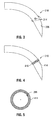
- FIG. 3 is a side, plan view of the needle seen in FIG. 1 including an alternate embodiment of the reduction structure;
- FIG. 4 is a side, plan view of the needle seen in FIG. 1 including another embodiment of the reduction structure;
- FIG. 5 is a front, end view of the needle seen in FIG. 4 ;
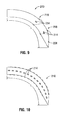
- FIGS. 6-11 are side, plan views of the needle seen in FIG. 1 illustrating additional embodiments of the reduction structure
- FIG. 12 is a front, end view of the needle seen in FIG. 11 ;
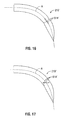
- FIGS. 13-19 are side, plan views of the needle seen in FIG. 1 illustrating additional embodiments of the reduction structure.
- FIG. 20 is a side, perspective view of the needle seen in FIG. 1 including an additional embodiment of the reduction structure.
- proximal should be understood as referring to the end of the presently disclosed surgical needle assembly, or any component thereof that is closest to a practitioner during proper use
- distal should be understood as referring to the end that is furthest from the practitioner during proper use
- filament should be understood as referring to any elongate member suitable for the intended purpose of joining tissue, including but not limited to sutures, ligatures, and surgical tape
- tissue should be understood as referring to any bodily tissue, including but not limited to skin, fascia, ligaments, tendons, muscle, and bone.
- FIG. 1 illustrates one embodiment of a surgical needle assembly, referred to generally by reference character 1000, that includes a filament 100 and a needle 200 that is attachable to an end 102 of the filament 100.
- the filament 100 can be formed from any suitable biocompatible material of either the absorbable or non-absorbable variety, including but not limited to catgut, silk, nylon, polyesters, polyethylene, polypropylene, steel, polymeric and copolymeric materials, and stainless steel.
- the filament 100 has a measure of flexibility such that the filament 100 can be manipulated by a practitioner to join adjacent sections of tissue together.
- the filament 100 may be used to repair or close an incision, wound, or the like using conventional suturing techniques.
- the needle 200 may be formed of any suitable biocompatible material, including but not limited to stainless steel or polymeric materials, and may define a configuration that is partially or wholly arcuate, as shown, or substantially linear, as seen in FIG. 1A .
- the needle 200 is an elongate member that includes proximal and distal ends 202, 204, respectively, and a shaft 206 that extends therebetween.
- the proximal end 202 of the needle 200 is attachable, either releasably or fixedly to the end 102 of the filament 100, and may be attached thereto in any suitable manner.
- the proximal end 202 of the needle 200 includes a bore 208 that is configured and dimensioned to receive the end 102 of the filament 100.
- the filament 100 and the needle 200 may be integrally formed.
- the distal end 204 of the needle 200 may exhibit any configuration suitable for the intended purpose of facilitating the penetration of tissue. While the needle 200 is illustrated as including a distal end 204 that is pointed or incisive, alternatively, the distal end 204 may be substantially blunt.
- the shaft 206 extends from the proximal end 202 to the distal end 204 along an axis "A" to define a length "L".
- the shaft 206 includes reduction structure 210 that extends away, i.e., outwardly of, or inwardly from, an outer surface 212 of the shaft 206.
- the reduction structure 210 is configured and dimensioned to create gradual, smooth topographical variations in outer surface 212 of the shaft 206 to decrease the surface area of the needle 200 that is in contact with tissue during use. By decreasing the surface area of the needle 200 that is in contact with tissue, the reduction structure 210 reduces the force necessary to advance the needle 200, and facilitates the atraumatic insertion and removal thereof.
- the reduction structure 210 includes one or more protrusions 214 extending outwardly of the outer surface 212 of the shaft 206.
- the reduction structure 210 includes three protrusions 214 that are spaced about the periphery of the needle 200.
- the protrusions 214 may be spaced equally from each other to define a distance "C" therebetween, as seen in FIGS. 1-2 , or alternatively, the spacing between adjacent protrusions 214 may vary.
- the protrusions 214 may each define an equivalent dimension "D" as shown, or alternatively, may vary in size.
- the protrusions 214 may be present in fewer or greater numbers and/or may be arranged differently, as described below.
- the protrusions 214 may exhibit any other suitable geometric configuration.
- the reduction structure 210 may include protrusions 314 that are substantially circular, as seen in FIG. 3 .
- the reduction structure 210 may include one or more protrusions 414 having an arcuate configuration such that the protrusions 210 extend continuously about the periphery of the shaft 206 to define one or more ribs 416, as seen in FIGS. 4-5 .
- the reduction structure 210 may alternatively include one or more protrusions 416 attributing a threaded configuration to the outer surface 212 of the needle 200, as seen in FIG. 6 .
- the reduction structure 210 may include protrusions 514 that are substantially linear in configuration, as seen in FIG. 7 .
- the linear protrusions 514 may extend along the axis "A", as seen in FIG. 7 , or alternatively, may extend in transversely in relation thereto, as seen in FIG. 8 . While the reduction structure 210 has been described and illustrated as including only a single variety of protrusion in the embodiments seen in FIGS. 1-8 , it should be appreciated that alternate embodiments of the reduction structure 210 may include any suitable combination of the aforedescribed protrusions.
- the protrusions 214 may be are arranged about the periphery of the shaft 206 to define a single band 218. Alternatively, however, the protrusions 210 may be arranged to define a plurality of bands 218 that are spaced along the length "L" of the shaft 206, as seen in FIG. 9 , or the protrusions 214 may be positioned uniformly along the length "L" of the shaft, as seen in FIG. 10 .
- the reduction structure 210' includes one or more indentations 214' extending inwardly from the outer surface 212 of the shaft 206.
- the reduction structure 210' is illustrate as including three indentations 214' that are spaced about the periphery of the needle 200.
- the indentations 214' may be spaced equally from each other to define a distance "C1" therebetween, as seen in FIGS. 11-12 , or alternatively, the spacing between adjacent indentations 214' may vary.
- the indentations 214' may each define an equivalent dimension "D1" as shown, or alternatively, may vary in size.
- the indentations 214' may be present in fewer or greater numbers and/or may be arranged differently, as described below.
- the reduction structure 210' may include indentations 314' that are substantially circular, as seen in FIG. 13 .
- the reduction structure 210' may include indentations 414' having an arcuate configuration such that the indentations 414' extend continuously about the periphery of the shaft 206 to define one or more channels 416', as seen in FIG. 14 .
- the reduction structure 210' may alternatively include one or more indentations 416' attributing a threaded configuration to the outer surface 212 of the needle 200, as seen in FIG. 15 .
- the reduction structure 210 may include indentations 514' that are substantially linear in configuration, as seen in FIG. 16 .
- the linear indentations 514' may extend along the axis "A", as seen in FIG. 16 , or alternatively, may extend transversely in relation thereto, as seen in FIG. 17 .
- the reduction structure 210' may include indentations 214' that are arranged about the periphery of the shaft 206 to define a single band 218'.
- the indentations 214' may be arranged to define a plurality of bands 218' that are spaced along the length "L" of the shaft 206, as seen in FIG. 18 , or the indentations 214' may be positioned uniformly along the length "L" of the shaft 206, as seen in FIG. 19 .
- FIG. 20 illustrates the needle 200 including another embodiment of the reduction structure, referred to generally by reference character 310.
- the reduction structure 310' includes a combination of protrusions and indentations. Although illustrated as including the protrusions 218 discussed above with respect to FIG. 1 and the indentations 218' discussed above with respect to FIG. 11 , in alternate embodiments of the reduction structure 310, any of the aforedescribed protrusions or indentations may be included, either alone or in combination.
- the reduction structure 210, 210', 310 described above with reference to FIGS. 1-10 , FIGS. 11-19 , and FIG. 20 , respectively, may be formed through any suitable method of manufacture.
- the indentations 214' of the reduction structure 210' may be formed by grinding or milling the outer surface 212 of the needle 202, e.g., through the use of mechanical apparatus or lasers, or alternatively, the needle 200 may be cast in a die configured and dimensioned to form the indentations 214'.
Abstract
Description
- The present disclosure relates generally to apparatus for securing together tissue. More particularly, the present disclosure relates to a needle for use during surgical procedures including a reduced surface area to facilitate advancement of the needle through tissue.
- In surgical procedures, sutures are used to repair openings in skin, internal organs, blood vessels, and the like, as well as to join various tissues together. Generally, sutures are attached to a surgical needle that is forced through tissue to create an opening through which the suture may be drawn. However, contact between the surgical needle and the tissue can create forces of adhesion that can inhibit advancement of the needle, thus necessitating the application of increased force and potentially resulting in increased tissue trauma.
- To address this concern, many surgical needles include structure that limits contact between the needle's outer surface and the tissue. For example,
U.S. Patent No. 3,160,157 to Chisman (hereinafter "Chisman") andU.S. Patent No. 5,002,565 to McGregor (hereinafter "McGregor I") each describe surgical needles that include a plurality of raised edges or ribs defining recessed portions therebetween.U.S. Patent No. 5,853,423 to McGregor et al . (hereinafter "McGregor II") discusses a surgical needle that includes grooves defined in the outer surface. However, the edges discussed in both Chisman and McGregor I and the grooves described in McGregor II extend uninterruptedly along a substantial portion of the needle's length, thereby unnecessarily compromising the strength of the needle. Additionally,U.S. Patent Publication No. 2006/0173491 to Meade et al . (hereinafter "Meade") describes an arcuate suturing needle that includes a plurality of notches formed in an outer surface. However, the notches constitute abrupt, pronounced variations in the outer surface of the needle, and are configured and dimensioned to facilitate engagement with an external structure, such as a drive mechanism or a pin. Consequently, were the Meade needle to be used in an alternate application, e.g., without the drive mechanism, the notches may snag or catch the tissue, thereby resulting in unnecessary trauma. - Accordingly, a need remains in the art for a surgical needle including structure that facilitates atraumatic insertion of the needle through tissue by decreasing contact between the outer surface of the needle and the tissue, and thus, the amount of force required to advance the needle, without unnecessarily compromising the structural integrity or strength of the needle.
- In one aspect of the present disclosure, a surgical needle is disclosed including a proximal end that is adapted for connection with a surgical filament, a distal end, and a shaft extending therebetween. An outer surface of the shaft includes reduction structure positioned intermittently along the length of the shaft. The reduction structure is configured and dimensioned to reduce contact between the surgical needle and tissue, and to facilitate atraumatic insertion and passage of the surgical needle through the tissue during use.
- In one embodiment, the reduction structure includes at least one protrusion that extends outwardly from the outer surface of the shaft. The at least one protrusion may define any suitable geometric configuration, including but not limited to a substantially oval, substantially circular, substantially arcuate, or substantially linear configuration. In this embodiment of the reduction structure, the at least one protrusion may be configured such that the outer surface of the shaft is threaded. In an alternative embodiment, the at least one protrusion may include a plurality of protrusions that are spaced about a periphery of the shaft. In this embodiment, the plurality protrusions may be positioned uniformly, or randomly, about the outer surface of the shaft.
- In an alternate embodiment of the reduction structure, the reduction structure includes at least one indentation extending inwardly from the outer surface of the shaft. The at least one indentation may define any suitable geometric configuration, including but not limited to a substantially oval, substantially circular, substantially arcuate, or substantially linear configuration. In one embodiment of the reduction structure, the at least one indentation may be configured such that the outer surface of the shaft is threaded. In an alternative embodiment, the at least one indentation may include a plurality of indentations that are spaced about a periphery of the shaft. In this embodiment, the plurality of protrusions may be positioned uniformly, or randomly, about the outer surface of the shaft.
- In an alternate aspect of the present disclosure, a surgical needle assembly is disclosed that includes a surgical filament connected to a needle. The needle includes a shaft with an outer surface having at least one protrusion associated therewith. The at least one protrusion extends outwardly from the shaft and is configured and dimensioned to reduce contact between the shaft, and to facilitate atraumatic insertion and passage of the surgical needle through the tissue during use.
- The at least one protrusion may include a plurality of protrusions spaced along a length of the shaft, and/or a plurality of protrusions spaced about a periphery of the shaft.
- In another aspect of the present, a method of manufacturing a surgical needle is disclosed that includes the steps of providing an elongate member and altering an outer surface of the elongate member to include reduction structure positioned along the elongate member. The reduction structure is positioned intermittently along a length of the elongate member and is configured and dimensioned to reduce contact between the elongate member and tissue, and to facilitate atraumatic insertion and passage of the elongate member through the tissue during use.
- Various embodiments of the present disclosure are described herein below with reference to the drawings, wherein:
-
FIG. 1 is a side, perspective view of a surgical needle assembly including a filament and a needle incorporating reduction structure in accordance one embodiment of the present disclosure; -
FIG. 1A is a side, perspective view of an alternate embodiment of the needle seen inFIG. 1 exhibiting a substantially linear configuration; -
FIG. 2 is a front, end view of the needle seen inFIG. 1 ; -
FIG. 3 is a side, plan view of the needle seen inFIG. 1 including an alternate embodiment of the reduction structure; -
FIG. 4 is a side, plan view of the needle seen inFIG. 1 including another embodiment of the reduction structure; -
FIG. 5 is a front, end view of the needle seen inFIG. 4 ; -
FIGS. 6-11 are side, plan views of the needle seen inFIG. 1 illustrating additional embodiments of the reduction structure; -
FIG. 12 is a front, end view of the needle seen inFIG. 11 ; -
FIGS. 13-19 are side, plan views of the needle seen inFIG. 1 illustrating additional embodiments of the reduction structure; and -
FIG. 20 is a side, perspective view of the needle seen inFIG. 1 including an additional embodiment of the reduction structure. - In the following description and in the accompanying drawings, in which like references numbers identify similar or identical elements, the term "proximal" should be understood as referring to the end of the presently disclosed surgical needle assembly, or any component thereof that is closest to a practitioner during proper use, while the term "distal" should be understood as referring to the end that is furthest from the practitioner during proper use. Additionally, the term "filament" should be understood as referring to any elongate member suitable for the intended purpose of joining tissue, including but not limited to sutures, ligatures, and surgical tape, and the term "tissue" should be understood as referring to any bodily tissue, including but not limited to skin, fascia, ligaments, tendons, muscle, and bone.
-
FIG. 1 illustrates one embodiment of a surgical needle assembly, referred to generally byreference character 1000, that includes afilament 100 and aneedle 200 that is attachable to anend 102 of thefilament 100. Thefilament 100 can be formed from any suitable biocompatible material of either the absorbable or non-absorbable variety, including but not limited to catgut, silk, nylon, polyesters, polyethylene, polypropylene, steel, polymeric and copolymeric materials, and stainless steel. Desirably, thefilament 100 has a measure of flexibility such that thefilament 100 can be manipulated by a practitioner to join adjacent sections of tissue together. As an illustrative example, thefilament 100 may be used to repair or close an incision, wound, or the like using conventional suturing techniques. - With reference now to
FIG. 2 as well, theneedle 200 will be discussed. Theneedle 200 may be formed of any suitable biocompatible material, including but not limited to stainless steel or polymeric materials, and may define a configuration that is partially or wholly arcuate, as shown, or substantially linear, as seen inFIG. 1A . - The
needle 200 is an elongate member that includes proximal anddistal ends shaft 206 that extends therebetween. Theproximal end 202 of theneedle 200 is attachable, either releasably or fixedly to theend 102 of thefilament 100, and may be attached thereto in any suitable manner. For instance, in the embodiment of theneedle assembly 1000 illustrated inFIG. 1 , theproximal end 202 of theneedle 200 includes abore 208 that is configured and dimensioned to receive theend 102 of thefilament 100. In an alternate embodiment, however, thefilament 100 and theneedle 200 may be integrally formed. - The
distal end 204 of theneedle 200 may exhibit any configuration suitable for the intended purpose of facilitating the penetration of tissue. While theneedle 200 is illustrated as including adistal end 204 that is pointed or incisive, alternatively, thedistal end 204 may be substantially blunt. - The
shaft 206 extends from theproximal end 202 to thedistal end 204 along an axis "A" to define a length "L". Theshaft 206 includesreduction structure 210 that extends away, i.e., outwardly of, or inwardly from, anouter surface 212 of theshaft 206. Thereduction structure 210 is configured and dimensioned to create gradual, smooth topographical variations inouter surface 212 of theshaft 206 to decrease the surface area of theneedle 200 that is in contact with tissue during use. By decreasing the surface area of theneedle 200 that is in contact with tissue, thereduction structure 210 reduces the force necessary to advance theneedle 200, and facilitates the atraumatic insertion and removal thereof. - In the embodiment of the
reduction structure 210 seen inFIGS. 1 and 2 , thereduction structure 210 includes one ormore protrusions 214 extending outwardly of theouter surface 212 of theshaft 206. As illustrated, thereduction structure 210 includes threeprotrusions 214 that are spaced about the periphery of theneedle 200. Theprotrusions 214 may be spaced equally from each other to define a distance "C" therebetween, as seen inFIGS. 1-2 , or alternatively, the spacing betweenadjacent protrusions 214 may vary. Theprotrusions 214 may each define an equivalent dimension "D" as shown, or alternatively, may vary in size. In additional embodiments of thereduction structure 210, theprotrusions 214 may be present in fewer or greater numbers and/or may be arranged differently, as described below. - Although illustrated as substantially oval in configuration, the
protrusions 214 may exhibit any other suitable geometric configuration. For example, thereduction structure 210 may includeprotrusions 314 that are substantially circular, as seen inFIG. 3 . Instead, thereduction structure 210 may include one ormore protrusions 414 having an arcuate configuration such that theprotrusions 210 extend continuously about the periphery of theshaft 206 to define one ormore ribs 416, as seen inFIGS. 4-5 . Thereduction structure 210 may alternatively include one ormore protrusions 416 attributing a threaded configuration to theouter surface 212 of theneedle 200, as seen inFIG. 6 . In another variation, thereduction structure 210 may includeprotrusions 514 that are substantially linear in configuration, as seen inFIG. 7 . Thelinear protrusions 514 may extend along the axis "A", as seen inFIG. 7 , or alternatively, may extend in transversely in relation thereto, as seen inFIG. 8 . While thereduction structure 210 has been described and illustrated as including only a single variety of protrusion in the embodiments seen inFIGS. 1-8 , it should be appreciated that alternate embodiments of thereduction structure 210 may include any suitable combination of the aforedescribed protrusions. - Referring again to
FIG. 1 , theprotrusions 214 may be are arranged about the periphery of theshaft 206 to define asingle band 218. Alternatively, however, theprotrusions 210 may be arranged to define a plurality ofbands 218 that are spaced along the length "L" of theshaft 206, as seen inFIG. 9 , or theprotrusions 214 may be positioned uniformly along the length "L" of the shaft, as seen inFIG. 10 . - Referring now to
FIGS. 11-19 , another embodiment of the reduction structure, referred to generally by reference character 210', will be discussed. In this embodiment, the reduction structure 210' includes one or more indentations 214' extending inwardly from theouter surface 212 of theshaft 206. - In the embodiment of the reduction structure 210' seen in
FIGS. 11-12 , the reduction structure 210' is illustrate as including three indentations 214' that are spaced about the periphery of theneedle 200. The indentations 214' may be spaced equally from each other to define a distance "C1" therebetween, as seen inFIGS. 11-12 , or alternatively, the spacing between adjacent indentations 214' may vary. The indentations 214' may each define an equivalent dimension "D1" as shown, or alternatively, may vary in size. In additional embodiments of the reduction structure 210', the indentations 214' may be present in fewer or greater numbers and/or may be arranged differently, as described below. - While the indentations 214' are illustrated as substantially oval on configuration, any other suitable geometric configuration may be employed. For example, the reduction structure 210' may include indentations 314' that are substantially circular, as seen in
FIG. 13 . Instead, the reduction structure 210' may include indentations 414' having an arcuate configuration such that the indentations 414' extend continuously about the periphery of theshaft 206 to define one or more channels 416', as seen inFIG. 14 . The reduction structure 210' may alternatively include one or more indentations 416' attributing a threaded configuration to theouter surface 212 of theneedle 200, as seen inFIG. 15 . In another variation, thereduction structure 210 may include indentations 514' that are substantially linear in configuration, as seen inFIG. 16 . The linear indentations 514' may extend along the axis "A", as seen inFIG. 16 , or alternatively, may extend transversely in relation thereto, as seen inFIG. 17 . - Referring again to
FIG. 11 , the reduction structure 210' may include indentations 214' that are arranged about the periphery of theshaft 206 to define a single band 218'. Alternatively, however, the indentations 214' may be arranged to define a plurality of bands 218' that are spaced along the length "L" of theshaft 206, as seen inFIG. 18 , or the indentations 214' may be positioned uniformly along the length "L" of theshaft 206, as seen inFIG. 19 . -
FIG. 20 illustrates theneedle 200 including another embodiment of the reduction structure, referred to generally byreference character 310. In this embodiment, the reduction structure 310' includes a combination of protrusions and indentations. Although illustrated as including theprotrusions 218 discussed above with respect toFIG. 1 and the indentations 218' discussed above with respect toFIG. 11 , in alternate embodiments of thereduction structure 310, any of the aforedescribed protrusions or indentations may be included, either alone or in combination. - The
reduction structure FIGS. 1-10 ,FIGS. 11-19 , andFIG. 20 , respectively, may be formed through any suitable method of manufacture. Referring toFIG. 18 as an example, the indentations 214' of the reduction structure 210' may be formed by grinding or milling theouter surface 212 of theneedle 202, e.g., through the use of mechanical apparatus or lasers, or alternatively, theneedle 200 may be cast in a die configured and dimensioned to form the indentations 214'. - Persons skilled in the art will understand that the devices and methods specifically described herein and illustrated in the accompanying drawings are intended to be construed as non-limiting, exemplary embodiments, and that the features illustrated or described in connection with one exemplary embodiment may be combined with the features of other embodiments. Additionally, one skilled in the art will appreciate further features and advantages of the disclosure based on the above-described embodiments. As such, the disclosure is not to be limited by what has been particularly shown and described, except as indicated by the appended claims.
Claims (9)
- A surgical needle comprising:a proximal end adapted for attachment to a surgical filament, a distal end, and a shaft extending therebetween, wherein an outer surface of the shaft includes reduction structure positioned intermittently along a length of the shaft, the reduction structure being configured and dimensioned to reduce contact between the surgical needle and tissue, wherein the reduction structure is configured and dimensioned to facilitate atraumatic insertion and passage of the surgical needle through the tissue during use.
- The surgical needle of claim 1, wherein the reduction structure includes at least one protrusion extending outwardly from the outer surface of the shaft.
- The surgical needle of claim 2, wherein the at least one protrusion includes a plurality of protrusions spaced about a periphery of the shaft; or the surgical needle of claim 2, wherein the at least one protrusion defines a substantially oval configuration; or the surgical needle of claim 2, wherein the at least one protrusion defines a substantially circular configuration; or the surgical needle of claim 2, wherein the at least one protrusion defines a substantially arcuate configuration; or the surgical needle of claim 2, wherein the at least one protrusion defines a substantially linear configuration; or the surgical needle of claim 2, wherein the at least one protrusion is configured such that the outer surface of the needle defines at least a partial threaded configuration; or the surgical needle of claim 2, wherein the at least one protrusion includes a plurality of protrusions positioned uniformly about the outer surface of the shaft.
- The surgical needle of claim 1, wherein the reduction structure includes at least one indentation extending inwardly from the outer surface of the shaft.
- The surgical needle of claim 4, wherein the at least one indentation includes a plurality of indentations spaced about a periphery of the shaft; or the surgical needle of claim 4, wherein the at least one indentation defines a substantially oval configuration; or the surgical needle of claim 4, wherein the at least one indentation defines a substantially circular configuration; or the surgical needle of claim 4, wherein the at least one indentation defines a substantially arcuate configuration; or the surgical needle of claim 4, wherein the at least one indentation defines a substantially linear configuration; or the surgical needle of claim 4, wherein the at least one indentation is configured such that the outer surface of the needle defines a threaded configuration; or the surgical needle of claim 4, wherein the at least one indentation includes a plurality of indentations positioned uniformly about the outer surface of the shaft.
- A surgical needle assembly, comprising:a surgical filament; anda needle attached to the surgical filament and including a shaft with an outer surface having at least one protrusion associated therewith, the at least one protrusion extending outwardly from the shaft and being configured and dimensioned to reduce contact between the shaft and tissue, wherein the at least one protrusion is configured and dimensioned to facilitate atraumatic insertion and passage of the surgical needle through the tissue during use.
- The surgical needle of claim 6, wherein the at least one protrusion includes a plurality of protrusions spaced along a length of the shaft.
- The surgical needle of claim 6, wherein the at least one protrusion includes a plurality of protrusions spaced about a periphery of the shaft.
- A method of manufacturing a surgical needle, comprising the steps of:providing an elongate member; andaltering an outer surface of the elongate member to include reduction structure positioned along a length of the elongate member, the reduction structure being positioned intermittently along a length of the elongate member and configured and dimensioned to reduce contact between the elongate member and tissue, wherein the reduction structure is configured and dimensioned to facilitate atraumatic insertion and passage of the surgical needle through the tissue during use.
Applications Claiming Priority (1)
| Application Number | Priority Date | Filing Date | Title |
|---|---|---|---|
| US12/187,719 US20100036415A1 (en) | 2008-08-07 | 2008-08-07 | Surgical needle with reduced contact area |
Publications (2)
| Publication Number | Publication Date |
|---|---|
| EP2151198A2 true EP2151198A2 (en) | 2010-02-10 |
| EP2151198A3 EP2151198A3 (en) | 2013-06-12 |
Family
ID=41134544
Family Applications (1)
| Application Number | Title | Priority Date | Filing Date |
|---|---|---|---|
| EP09251933.9A Withdrawn EP2151198A3 (en) | 2008-08-07 | 2009-08-04 | Surgical needle with reduced contact area |
Country Status (2)
| Country | Link |
|---|---|
| US (1) | US20100036415A1 (en) |
| EP (1) | EP2151198A3 (en) |
Cited By (1)
| Publication number | Priority date | Publication date | Assignee | Title |
|---|---|---|---|---|
| WO2022056216A1 (en) * | 2020-09-10 | 2022-03-17 | Ergosurgical Group Corp. | Curved suture needles having a non-smooth profile |
Families Citing this family (23)
| Publication number | Priority date | Publication date | Assignee | Title |
|---|---|---|---|---|
| EP2308391B1 (en) | 2001-06-14 | 2016-08-31 | Endoevolution, Llc | Apparatus for surgical suturing with thread management |
| US9775600B2 (en) | 2010-10-01 | 2017-10-03 | Endoevolution, Llc | Devices and methods for minimally invasive suturing |
| US7976555B2 (en) | 2008-07-17 | 2011-07-12 | Endoevolution, Llc | Apparatus and method for minimally invasive suturing |
| US8123764B2 (en) | 2004-09-20 | 2012-02-28 | Endoevolution, Llc | Apparatus and method for minimally invasive suturing |
| EP1981406B1 (en) | 2006-01-27 | 2016-04-13 | Suturtek Incorporated | Apparatus for tissue closure |
| CN102196836B (en) * | 2008-10-25 | 2013-12-18 | 金允圣 | Structure of needle for syringe |
| JP5188491B2 (en) * | 2009-12-28 | 2013-04-24 | ケイセイ医科工業株式会社 | Suture needle |
| JP5017483B1 (en) * | 2011-08-05 | 2012-09-05 | 株式会社医研工業 | Manufacturing method of eyeless suture needle |
| CN103889343B (en) * | 2011-08-08 | 2017-11-14 | 远藤发展有限责任公司 | Apparatus and method for minimally invasive suture |
| WO2013165942A1 (en) | 2012-05-01 | 2013-11-07 | Brigham And Women's Hospital, Inc. | Suturing device for laparoscopic procedures |
| US20140171977A1 (en) | 2012-12-13 | 2014-06-19 | Ethicon Endo-Surgery, Inc. | Pawl Mechanism in Circular Needle Applier |
| US9375212B2 (en) | 2014-06-06 | 2016-06-28 | Ethicon Endo-Surgery, Llc | Circular needle applier with cleats |
| US20150351749A1 (en) | 2014-06-06 | 2015-12-10 | Ethicon Endo-Surgery, Inc. | Needle Cartridge with Moveable Cover |
| US9526495B2 (en) | 2014-06-06 | 2016-12-27 | Ethicon Endo-Surgery, Llc | Articulation control for surgical instruments |
| US10022120B2 (en) | 2015-05-26 | 2018-07-17 | Ethicon Llc | Surgical needle with recessed features |
| USD800306S1 (en) | 2015-12-10 | 2017-10-17 | Ethicon Llc | Surgical suturing device |
| WO2018119459A1 (en) | 2016-12-23 | 2018-06-28 | Brigham And Women's Hospital, Inc. | Systems and methods for suturing tissue |
| USD865964S1 (en) | 2017-01-05 | 2019-11-05 | Ethicon Llc | Handle for electrosurgical instrument |
| US20180242967A1 (en) | 2017-02-26 | 2018-08-30 | Endoevolution, Llc | Apparatus and method for minimally invasive suturing |
| US10292698B2 (en) | 2017-07-27 | 2019-05-21 | Endoevolution, Llc | Apparatus and method for minimally invasive suturing |
| USD895112S1 (en) | 2018-11-15 | 2020-09-01 | Ethicon Llc | Laparoscopic bipolar electrosurgical device |
| US20220071621A1 (en) * | 2020-09-10 | 2022-03-10 | Ergosurgical Group Corp. | Tapered transition portion for suture needles |
| EP4346633A2 (en) * | 2021-05-28 | 2024-04-10 | Ergosurgical Group Corp. | Curved suture needle extension |
Citations (4)
| Publication number | Priority date | Publication date | Assignee | Title |
|---|---|---|---|---|
| US3160157A (en) | 1962-03-29 | 1964-12-08 | Ethicon Inc | Surgical needle |
| US5002565A (en) | 1989-10-19 | 1991-03-26 | Ethicon, Inc. | Surgical needle configuration with star shaped cross-section |
| US5853423A (en) | 1993-10-20 | 1998-12-29 | Ethicon, Inc. | Process for the manufacture of suture needles and needles produced thereby |
| US20060173491A1 (en) | 2001-06-14 | 2006-08-03 | Suturtek Incorporated | Needle for suturing instrument |
Family Cites Families (98)
| Publication number | Priority date | Publication date | Assignee | Title |
|---|---|---|---|---|
| US312408A (en) * | 1885-02-17 | Surgical needle | ||
| US278459A (en) * | 1883-05-29 | Sewing-needle | ||
| US1607479A (en) * | 1926-11-16 | X j john t | ||
| US722105A (en) * | 1902-11-10 | 1903-03-03 | Ben E Hervey | Needle-awl. |
| US1633726A (en) * | 1923-10-13 | 1927-06-28 | Dziuk Edmund | Needle |
| US1592897A (en) * | 1925-12-02 | 1926-07-20 | Harry D Morton | Needle and method of making the same |
| US1844364A (en) * | 1931-01-12 | 1932-02-09 | Robert J Lowrie | Needle |
| US2041674A (en) * | 1934-10-15 | 1936-05-19 | Southern Textile Machinery Com | Needle |
| US2781957A (en) * | 1952-06-30 | 1957-02-19 | Szen Anastasia S Le | Reweaving needles |
| US3005428A (en) * | 1958-06-24 | 1961-10-24 | Singer Mfg Co | Sewing machine needle with cooling characteristics |
| US3154229A (en) * | 1961-06-23 | 1964-10-27 | George W Mount | Tufting needle |
| US3570497A (en) * | 1969-01-16 | 1971-03-16 | Gerald M Lemole | Suture apparatus and methods |
| US3834599A (en) * | 1972-08-04 | 1974-09-10 | N Herr | Needle |
| US3754693A (en) * | 1972-08-04 | 1973-08-28 | N Herr | Needle |
| DE2342126C3 (en) * | 1972-11-15 | 1979-10-31 | Kanegafuchi Chemical Industry Co., Ltd., Osaka | Device for inserting pile threads into a carrier |
| FR2245207A5 (en) * | 1973-04-12 | 1975-04-18 | Delahousse Et Bruant Ets | |
| US3862611A (en) * | 1973-12-12 | 1975-01-28 | Maruzen Sewing Machine | Sewing machine needle |
| US3892240A (en) * | 1974-03-21 | 1975-07-01 | Charles Lanier Park | Surgical needle apparatus |
| US3910282A (en) * | 1974-05-22 | 1975-10-07 | American Cyanamid Co | Needling monofilament sutures |
| US3954072A (en) * | 1975-05-28 | 1976-05-04 | The Singer Company | Needles for tufting or the like |
| GB1571795A (en) * | 1975-12-01 | 1980-07-16 | Manuf Belge D Aiguilles Sa | Smoothing the eyes of metal needles |
| CH599025A5 (en) * | 1976-04-23 | 1978-05-12 | Grapha Holding Ag | |
| US4120255A (en) * | 1976-09-03 | 1978-10-17 | Shakespeare Company | Monofilament sewing thread |
| GB1601812A (en) * | 1977-03-09 | 1981-11-04 | Johansson A | Tufting |
| DE2834738C2 (en) * | 1977-08-10 | 1984-07-12 | Wool Research Organisation of New Zealand (Inc.), Lincoln, Canterbury | Needle for tufting machines |
| US4122788A (en) * | 1977-10-03 | 1978-10-31 | The Torrington Company | Sewing machine needle |
| US4117791A (en) * | 1977-12-14 | 1978-10-03 | The Singer Company | Dual color coded sewing machine needles |
| US4527564A (en) * | 1980-02-06 | 1985-07-09 | Janome Sewing Machine Co. Ltd. | Suturing needle for medical operation |
| DE3202650A1 (en) * | 1982-01-28 | 1983-08-04 | Dr. Ruhland Nachfolger GmbH, 8425 Neustadt | Surgical needle |
| NZ201452A (en) * | 1982-08-02 | 1985-12-13 | Wool Res Organisation | Tufting machine needle |
| US4513747A (en) * | 1982-10-25 | 1985-04-30 | Ethicon, Inc. | Hard tissue surgical needle |
| NL8501786A (en) * | 1985-06-21 | 1987-01-16 | Drukker D & Zn Nv | METHOD FOR MANUFACTURING MICROSURGIC BONDING NEEDLES, AND MICROSURING BINDING NEEDLES OBTAINED |
| EP0232444A1 (en) * | 1986-02-19 | 1987-08-19 | Yasuo Nakamura | A suture needle and its manufacturing processes |
| GB8707540D0 (en) * | 1987-03-30 | 1987-05-07 | King E M | Embroidery |
| US4799484A (en) * | 1987-04-10 | 1989-01-24 | Ethicon, Inc. | Tapered I-beam surgical needles |
| FR2619129B1 (en) * | 1987-08-07 | 1990-02-09 | Mas Richard | SEWING THREAD NEEDLE |
| US4966143A (en) * | 1988-12-06 | 1990-10-30 | Meinershagen Charles I | Surgical wire guide |
| US5002564A (en) * | 1989-06-19 | 1991-03-26 | Ethicon, Inc. | Surgical needle configuration with spatula geometry |
| US4932961A (en) * | 1989-09-15 | 1990-06-12 | Ethicon, Inc. | Surgical needle configuration with five-sided cross-section |
| US5030228A (en) * | 1989-09-15 | 1991-07-09 | Ethicon, Inc. | Surgical needle configuration with five-sided cross-section |
| US5258016A (en) * | 1990-07-13 | 1993-11-02 | American Cyanamid Company | Suture anchor and driver assembly |
| US5222977A (en) * | 1992-02-21 | 1993-06-29 | Esser Rene D | Surgical needle with an adjustable eye |
| US5403328A (en) * | 1992-04-22 | 1995-04-04 | United States Surgical Corporation | Surgical apparatus and method for suturing body tissue |
| US5387227A (en) * | 1992-09-10 | 1995-02-07 | Grice; O. Drew | Method for use of a laparo-suture needle |
| US5403346A (en) * | 1992-12-31 | 1995-04-04 | Loeser; Edward A. | Self-affixing suture assembly |
| US5330488A (en) * | 1993-03-23 | 1994-07-19 | Goldrath Milton H | Verres needle suturing kit |
| US5501691A (en) * | 1993-03-23 | 1996-03-26 | Goldrath; Milton H. | Verres needle suturing device |
| US5403344A (en) * | 1993-07-22 | 1995-04-04 | American Cyanamid Co. | Multi-faceted surgical needle |
| US5569301A (en) * | 1993-10-08 | 1996-10-29 | United States Surgical Corporation | Surgical incision members for endoscopic suturing apparatus |
| US5342397A (en) * | 1993-10-18 | 1994-08-30 | Ethicon, Inc. | Cutting edge and tapercut needles having a blunt tip |
| US5478327A (en) * | 1993-10-18 | 1995-12-26 | Ethicon, Inc. | Surgical needle with decreased penetration |
| JP3442153B2 (en) * | 1994-08-23 | 2003-09-02 | マニー株式会社 | Suture Needle Mold and Suture Needle |
| JP2913372B2 (en) * | 1994-12-16 | 1999-06-28 | 株式会社コーテックス | Hollow needle for locking piece mounting machine |
| US5968076A (en) * | 1995-03-03 | 1999-10-19 | United States Surgical Corporation | Channel-bodied surgical needle and method of manufacture |
| US6056771A (en) * | 1995-06-02 | 2000-05-02 | United States Surgical Corporation | Radiused tip surgical needles and surgical incision members |
| US6129741A (en) * | 1995-06-10 | 2000-10-10 | Forschungszentrum Karlsruhe Gmbh | Surgical suturing needle |
| US5702462A (en) * | 1996-01-24 | 1997-12-30 | Oberlander; Michael | Method of meniscal repair |
| CA2197368A1 (en) * | 1996-02-15 | 1997-08-16 | Daniel J. Smith | Radiused hollow cutting edge needle |
| US5913875A (en) * | 1996-05-30 | 1999-06-22 | Ethicon, Inc. | Taper point needle |
| US5897572A (en) * | 1996-10-11 | 1999-04-27 | Cornell Research Foundation, Inc. | Microsurgical suture needle |
| US5730732A (en) * | 1996-12-04 | 1998-03-24 | Ethicon, Inc. | Non-magnetic stainless steel surgical needle |
| JP3789020B2 (en) * | 1997-02-12 | 2006-06-21 | マニー株式会社 | Suture needle and needle holder |
| US5741299A (en) * | 1997-03-05 | 1998-04-21 | Rudt; Louis L. | Puncture-proof suture needle assembly |
| US5928207A (en) * | 1997-06-30 | 1999-07-27 | The Regents Of The University Of California | Microneedle with isotropically etched tip, and method of fabricating such a device |
| US5972005A (en) * | 1998-02-17 | 1999-10-26 | Advanced Cardiovascular Systems, Ind. | Wound closure assembly and method of use |
| US6214030B1 (en) * | 1998-08-10 | 2001-04-10 | Mani, Inc. | Suture needle |
| IT1305535B1 (en) * | 1998-09-18 | 2001-05-09 | Ima Spa | NEEDLE PERFECTED TO CONNECT A FILTER BAG, CONTAINING AN INFUSION PRODUCT, AND A TAKE-OFF LABEL WITH A THREAD |
| US6019781A (en) * | 1998-10-16 | 2000-02-01 | Worland; Richard L. | Rotator cuff needle |
| US6723107B1 (en) * | 1999-04-19 | 2004-04-20 | Orthopaedic Biosystems Ltd. | Method and apparatus for suturing |
| DK1581162T3 (en) * | 1999-06-09 | 2011-08-01 | Ethicon Inc | Device for adjusting polymer implants on soft surfaces |
| DE19961218A1 (en) * | 1999-12-15 | 2001-07-05 | Ethicon Gmbh | Surgical needle for implanting a band |
| DE10008447C2 (en) * | 2000-02-23 | 2002-07-25 | Groz Beckert Kg | Sewing needle for multi-directional sewing |
| US20040249394A1 (en) * | 2001-08-06 | 2004-12-09 | Arthrex, Inc. | Compact suture punch with malleable needle |
| JP3962948B2 (en) * | 2002-02-28 | 2007-08-22 | 株式会社プロピア | Wig needle |
| AU2003220546A1 (en) * | 2002-03-26 | 2003-10-13 | Ethicon, Inc. | System and method for biopsy management |
| ES2385557T3 (en) * | 2002-07-17 | 2012-07-26 | Tyco Healthcare Group Lp | Joint effort needle |
| CA2491030C (en) * | 2002-07-17 | 2010-10-05 | Tyco Healthcare Group Lp | Surgical cobra head suture needle |
| JP4043319B2 (en) * | 2002-08-23 | 2008-02-06 | オルガン針株式会社 | Sewing needle |
| EP2394586B1 (en) * | 2002-10-04 | 2013-07-31 | Covidien LP | Sharpoint needle |
| JP2004141468A (en) * | 2002-10-25 | 2004-05-20 | Organ Needle Co Ltd | Sewing machine needle |
| JP3890013B2 (en) * | 2002-12-05 | 2007-03-07 | オリンパス株式会社 | Ultrasound puncture needle |
| DE10259642A1 (en) * | 2002-12-18 | 2004-07-22 | Fssb Chirurgische Nadeln Gmbh | Surgical needle, for sutures through tissue, is polished mechanically to give structured projections and recesses, to be treated with a non-stick materials and dark gilding for low contrast without gloss |
| US7481826B2 (en) * | 2003-09-30 | 2009-01-27 | Ethicon, Inc. | Fluid emitting suture needle |
| US20050251189A1 (en) * | 2004-05-07 | 2005-11-10 | Usgi Medical Inc. | Multi-position tissue manipulation assembly |
| WO2005069743A2 (en) * | 2004-01-23 | 2005-08-04 | Chalam Mahadevan | Suture needle and suture assembly |
| JP4243220B2 (en) * | 2004-05-26 | 2009-03-25 | 株式会社秋山製作所 | Suture needle |
| IL163209A (en) * | 2004-07-26 | 2009-08-03 | Yair Eilam | Sewing machine needle for stitching with a composite thread |
| US20060047309A1 (en) * | 2004-08-25 | 2006-03-02 | Cichocki Frank R Jr | Metal injection molded suture needles |
| JP4604140B2 (en) * | 2004-09-13 | 2010-12-22 | マニー株式会社 | Medical needle or blade |
| AU2005317128B2 (en) * | 2004-12-15 | 2011-08-18 | Cook Medical Technologies Llc | Flexible surgical needle device |
| US8211143B2 (en) * | 2005-03-31 | 2012-07-03 | David Stefanchik | Suturing device |
| US8118753B2 (en) * | 2005-08-18 | 2012-02-21 | Seoul National University Industry Foundation | Barb-wired micro needle made of single crystalline silicon and biopsy method and medicine injecting method using the same |
| US20070123935A1 (en) * | 2005-11-30 | 2007-05-31 | Myers Gene E | Method and apparatus for contemporaneous formation of a body structure opening and homologous pedicle |
| DE102006044788A1 (en) * | 2006-09-13 | 2008-03-27 | Aesculap Ag & Co. Kg | Surgical needle used during heart surgery has textured profile comprising of multiple indentations and in which lateral face region extends as far as needle point |
| EP2103262B1 (en) * | 2007-01-11 | 2013-02-27 | Mani, Inc. | Suturing needle |
| US20100268258A1 (en) * | 2007-12-11 | 2010-10-21 | Maxwell Timothy J | Safety scalpel |
| CN102196836B (en) * | 2008-10-25 | 2013-12-18 | 金允圣 | Structure of needle for syringe |
| US20120059247A1 (en) * | 2010-09-03 | 2012-03-08 | Speeg Trevor W V | Echogenic needle for biopsy device |
-
2008
- 2008-08-07 US US12/187,719 patent/US20100036415A1/en not_active Abandoned
-
2009
- 2009-08-04 EP EP09251933.9A patent/EP2151198A3/en not_active Withdrawn
Patent Citations (4)
| Publication number | Priority date | Publication date | Assignee | Title |
|---|---|---|---|---|
| US3160157A (en) | 1962-03-29 | 1964-12-08 | Ethicon Inc | Surgical needle |
| US5002565A (en) | 1989-10-19 | 1991-03-26 | Ethicon, Inc. | Surgical needle configuration with star shaped cross-section |
| US5853423A (en) | 1993-10-20 | 1998-12-29 | Ethicon, Inc. | Process for the manufacture of suture needles and needles produced thereby |
| US20060173491A1 (en) | 2001-06-14 | 2006-08-03 | Suturtek Incorporated | Needle for suturing instrument |
Cited By (1)
| Publication number | Priority date | Publication date | Assignee | Title |
|---|---|---|---|---|
| WO2022056216A1 (en) * | 2020-09-10 | 2022-03-17 | Ergosurgical Group Corp. | Curved suture needles having a non-smooth profile |
Also Published As
| Publication number | Publication date |
|---|---|
| EP2151198A3 (en) | 2013-06-12 |
| US20100036415A1 (en) | 2010-02-11 |
Similar Documents
| Publication | Publication Date | Title |
|---|---|---|
| EP2151198A2 (en) | Surgical needle with reduced contact area | |
| JP5868785B2 (en) | Barbed suture combined with a surgical needle | |
| US9675341B2 (en) | Emergency self-retaining sutures and packaging | |
| JP5710679B2 (en) | Barbed construct for barbed suture | |
| JP4493501B2 (en) | Back-tipped suture | |
| US8002796B2 (en) | Surgical suture needle with blunt spherical region | |
| KR101233954B1 (en) | Fully-Threaded Bioabsorbable Suture Anchor | |
| EP2108316A1 (en) | Loop suture | |
| US20030149447A1 (en) | Barbed surgical suture | |
| EP2145587A2 (en) | Differentiation of surgical filaments | |
| EP0477020A1 (en) | Polymeric endoscopic ligature | |
| US20220054128A1 (en) | Knotless sutures including integrated closures | |
| US20220071621A1 (en) | Tapered transition portion for suture needles | |
| CN210990479U (en) | Suture and surgical suturing device | |
| CN210582548U (en) | Surgical suture | |
| US20220378416A1 (en) | Curved suture needle extension | |
| US20220071625A1 (en) | Curved suture needles having a non-smooth profile | |
| US20230083808A1 (en) | Suture needles with flexible and non-flexible components | |
| CA2671628A1 (en) | Differentiation of surgical filaments |
Legal Events
| Date | Code | Title | Description |
|---|---|---|---|
| PUAI | Public reference made under article 153(3) epc to a published international application that has entered the european phase |
Free format text: ORIGINAL CODE: 0009012 |
|
| AK | Designated contracting states |
Kind code of ref document: A2 Designated state(s): AT BE BG CH CY CZ DE DK EE ES FI FR GB GR HR HU IE IS IT LI LT LU LV MC MK MT NL NO PL PT RO SE SI SK SM TR |
|
| AX | Request for extension of the european patent |
Extension state: AL BA RS |
|
| RAP1 | Party data changed (applicant data changed or rights of an application transferred) |
Owner name: COVIDIEN LP |
|
| PUAL | Search report despatched |
Free format text: ORIGINAL CODE: 0009013 |
|
| AK | Designated contracting states |
Kind code of ref document: A3 Designated state(s): AT BE BG CH CY CZ DE DK EE ES FI FR GB GR HR HU IE IS IT LI LT LU LV MC MK MT NL NO PL PT RO SE SI SK SM TR |
|
| AX | Request for extension of the european patent |
Extension state: AL BA RS |
|
| RIC1 | Information provided on ipc code assigned before grant |
Ipc: A61B 17/06 20060101AFI20130506BHEP |
|
| STAA | Information on the status of an ep patent application or granted ep patent |
Free format text: STATUS: THE APPLICATION IS DEEMED TO BE WITHDRAWN |
|
| 18D | Application deemed to be withdrawn |
Effective date: 20131213 |