EP2156460B1 - Mass spectrometer - Google Patents
Mass spectrometer Download PDFInfo
- Publication number
- EP2156460B1 EP2156460B1 EP08750679A EP08750679A EP2156460B1 EP 2156460 B1 EP2156460 B1 EP 2156460B1 EP 08750679 A EP08750679 A EP 08750679A EP 08750679 A EP08750679 A EP 08750679A EP 2156460 B1 EP2156460 B1 EP 2156460B1
- Authority
- EP
- European Patent Office
- Prior art keywords
- mass
- signal
- intensity
- charge ratio
- arrival time
- Prior art date
- Legal status (The legal status is an assumption and is not a legal conclusion. Google has not performed a legal analysis and makes no representation as to the accuracy of the status listed.)
- Active
Links
Images

Classifications
-
- H—ELECTRICITY
- H01—ELECTRIC ELEMENTS
- H01J—ELECTRIC DISCHARGE TUBES OR DISCHARGE LAMPS
- H01J49/00—Particle spectrometers or separator tubes
- H01J49/0027—Methods for using particle spectrometers
- H01J49/0036—Step by step routines describing the handling of the data generated during a measurement
-
- H—ELECTRICITY
- H01—ELECTRIC ELEMENTS
- H01J—ELECTRIC DISCHARGE TUBES OR DISCHARGE LAMPS
- H01J49/00—Particle spectrometers or separator tubes
- H01J49/26—Mass spectrometers or separator tubes
- H01J49/34—Dynamic spectrometers
- H01J49/40—Time-of-flight spectrometers
Definitions
- the present invention relates to a mass spectrometer and a method of mass spectrometry.
- the preferred embodiment relates to an ion detector system and method of detecting ions.
- TDC Time to Digital Converters
- ADC Analogue to Digital Converters
- Time of Flight instruments incorporating Time to Digital Converters are known wherein signals resulting from ions arriving at an ion detector are recorded. Signals which satisfy defined detection criteria are recorded as a single binary value and are associated with a particular arrival time relative to a trigger event. A fixed amplitude threshold may be used to trigger recording of an ion arrival event. Ion arrival events which are subsequently recorded resulting from subsequent trigger events are combined to form a histogram of ion arrival events. The histogram of ion arrival events is then presented as a spectrum for further processing. Time to Digital Converters have the advantage of being able to detect relatively weak signals so long as the probability of multiple ions arriving at the ion detector in close temporal proximity remains relatively low. One disadvantage of Time to Digital Converters is that once an ion event has been recorded then there is a significant time interval or dead-time following the ion arrival event during which time no further ion arrival events can be recorded.
- Time to Digital Converters are unable to distinguish between a signal resulting from the arrival of a single ion at the ion detector and a signal resulting from the simultaneous arrival of multiple ions at the ion detector. This is due to the fact that the signal will only cross the threshold once irrespective of whether a single ion arrived at the ion detector or whether multiple ions arrived simultaneously at the ion detector. Both situations result in only a single ion arrival event being recorded.
- Time of Flight instruments which incorporate Analogue to Digital Converters are also known.
- An Analogue to Digital Converter is arranged to digitise signals resulting from ions arriving at the ion detector relative to a trigger event. The digitised signals resulting from subsequent trigger events are summed or averaged to produce a spectrum for further processing.
- a known signal averager is capable of digitising the output from ion detector electronics at a frequency of 3-4 GHz with eight or ten bit intensity resolution.
- One advantage of using an Analogue to Digital Converter as part of an ion detector system is that multiple ions which arrive substantially simultaneously at an ion detector and at relatively high signal intensities can be recorded without the ion detector suffering from distortion or saturation effects.
- the detection of low intensity signals is generally limited by electronic noise from the digitiser electronics, the ion detector and the amplifier system. The problem of electronic noise also effectively limits the dynamic range of the ion detector system.
- an Analogue to Digital Converter as part of an ion detector system (as opposed to using a Time to Digital Converter as part of the ion detector system) is that the analogue width of the signal generated by a single ion adds to the width of the ion arrival envelope for a particular mass to charge value in the final spectrum.
- a Time to Digital Converter only ion arrival times are recorded and hence the width of mass peaks in the final spectrum is determined only by the spread in ion arrival times for each mass peak and by variation in the voltage pulse height produced by an ion arrival relative to the signal threshold.
- a method of increasing the dynamic range of a transient recorder by using two Analogue to Digital Converters is known.
- a transient signal from an ion detector is amplified using two amplifiers having different gains.
- the two transients are digitized and the digitized data is combined on a time sample by time sample basis. High gain samples are used unless saturation is determined to occur at which point low gain data is substituted.
- the low gain data is scaled by the difference in gain between the two amplifiers.
- the result is a combined transient having a higher dynamic range than that obtainable using a single Analogue to Digital Converter.
- the combined transient is added to other transients which were collected previously using a known averager method. Once a preset number of transients have been averaged the resulting spectrum is stored to disk. See US-2006/0020400-A for an example of a detector with increased dynamic range.
- the known method also suffers from the same problems as a standard averaging Analogue to Digital Converter system in terms of reduced dynamic range due to the averaging of noise at low signal intensities and degraded resolution due to the digitization of the analogue ion peak width.
- Detectors using a combination of both Time to Digital Converter electronics and Analogue to Digital Converter electronics have been employed in an attempt to take advantage of the characteristics of each different type of recording device thereby attempting to increase the dynamic range and the observed time or mass resolution.
- Such systems are relatively complex to calibrate and operate.
- Such systems are also comparatively expensive. See US-2002/0175292-A for an example of a multiple detection system.
- WO-2006/129094 discloses a mass spectrometer.
- the step of determining the first intensity and arrival time, mass or mass to charge ratio data preferably further comprises marking or flagging each peak in the first set of peaks when the maximum digitised signal within a peak is determined as equalling or approaching a maximum or full scale digitised output or is otherwise saturated or approaching saturation.
- the step of determining the second intensity and arrival time, mass or mass to charge ratio data preferably further comprises marking or flagging each peak in the second set of peaks when the maximum digitised signal within a peak is determined as equalling or approaching a maximum or full scale digitised output or is otherwise saturated or approaching saturation.
- the step of combining the first intensity and arrival time, mass or mass to charge ratio data and the second intensity and arrival time, mass or mass to charge ratio data preferably further comprises:
- the method preferably further comprises scaling the peaks selected from the first set of peaks by a scale factor.
- the scale factor preferably corresponds with, is close to or is otherwise related to the ratio of the second gain to the first gain.
- the method preferably further comprises summing the combined data set with a plurality of other corresponding combined data sets to form a final spectrum.
- the method preferably further comprises processing the first summed digitised signal to detect a first set of peaks or ion arrival events and/or processing the second summed digitised signal to detect a second set of peaks or ion arrival events.
- the step of determining the first summed intensity and arrival time, mass or mass to charge ratio data from the first summed digitised signal preferably further comprises determining first summed intensity and arrival time, mass or mass to charge ratio data for each or at least some peaks or ion arrival events in the first set of peaks or ion arrival events.
- the step of determining the second summed intensity and arrival time, mass or mass to charge ratio data from the second summed digitised signal preferably further comprises determining second summed intensity and arrival time, mass or mass to charge ratio data for each or at least some peaks or ion arrival events in the second set of peaks or ion arrival events.
- the step of determining the first summed intensity and arrival time, mass or mass to charge ratio data preferably further comprises marking or flagging each peak or ion arrival event in the first set of peaks or ion arrival events when the maximum digitised signal within a peak or ion arrival event is determined as equalling or approaching a maximum or full scale digitised output or is otherwise saturated or approaching saturation.
- the step of determining the second summed intensity and arrival time, mass or mass to charge ratio data preferably further comprises marking or flagging each peak or ion arrival event in the second set of peaks or ion arrival events when the maximum digitised signal within a peak or ion arrival event is determined as equalling or approaching a maximum or full scale digitised output or is otherwise saturated or approaching saturation.
- the step of combining the first summed intensity and arrival time, mass or mass to charge ratio data and the second summed intensity and arrival time, mass or mass to charge ratio data preferably further comprises:
- the method preferably further comprises scaling the peaks or ion arrival events selected from the first set of peaks or ion arrival events by a scale factor.
- the scale factor preferably corresponds with, is close to or is otherwise related to the ratio of the second gain to the first gain.
- the method preferably further comprises processing the combined digitised signal to detect a set of peaks or ion arrival events.
- the step of determining the intensity and arrival time, mass or mass to charge ratio data from the combined digitised signal preferably further comprises determining intensity and arrival time, mass or mass to charge ratio data for each or at least some peaks or ion arrival events in the set of peaks or ion arrival events.
- the step of determining the intensity and arrival time, mass or mass to charge ratio data preferably further comprises marking or flagging each peak or ion arrival event in the first digitised signal when the maximum digitised signal within a peak or ion arrival event is determined as equalling or approaching a maximum or full scale digitised output or is otherwise saturated or approaching saturation.
- the step of determining the intensity and arrival time, mass or mass to charge ratio data preferably further comprises marking or flagging each peak or ion arrival event in the second digitised signal when the maximum digitised signal within a peak or ion arrival event is determined as equalling or approaching a maximum or full scale digitised output or is otherwise saturated or approaching saturation.
- the step of combining the first digitised signal and the second digitised signal preferably further comprises:
- the method preferably further comprises scaling the peaks or ion arrival events selected from the first digitised signal by a scale factor.
- the scale factor preferably corresponds with, is close to or is otherwise related to the ratio of the second gain to the first gain.
- the method preferably further comprises processing the final spectrum to detect a set of peaks or ion arrival events.
- the step of determining the intensity and arrival time, mass or mass to charge ratio data from the final spectrum preferably further comprises determining intensity and arrival time, mass or mass to charge ratio data for each or at least some peaks or ion arrival events in the set of peaks or ion arrival events.
- the step of determining the intensity and arrival time, mass or mass to charge ratio data preferably further comprises marking or flagging each peak or ion arrival event in the first digitised signal when the maximum digitised signal within a peak or ion arrival event is determined as equalling or approaching a maximum or full scale digitised output or is otherwise saturated or approaching saturation.
- the step of determining the intensity and arrival time, mass or mass to charge ratio data preferably further comprises marking or flagging each peak or ion arrival event in the second digitised signal when the maximum digitised signal within a peak or ion arrival event is determined as equalling or approaching a maximum or full scale digitised output or is otherwise saturated or approaching saturation.
- the step of combining the first digitised signal and the second digitised signal preferably further comprises:
- the method preferably further comprises scaling the peaks or ion arrival events selected from the first digitised signal by a scale factor.
- the scale factor preferably corresponds with, is close to or is otherwise related to the ratio of the second gain to the first gain.
- the method preferably further comprises processing the first digitised signal to detect a first set of peaks or ion arrival events and/or processing the second digitised signal to detect a second set of peaks or ion arrival events.
- the step of determining the first intensity and arrival time, mass or mass to charge ratio data from the first digitised signal preferably further comprises determining intensity and arrival time, mass or mass to charge ratio data for each or at least some peaks or ion arrival events in the first set of peaks or ion arrival events.
- the step of determining the second intensity and arrival time, mass or mass to charge ratio data from the second digitised signal preferably further comprises determining intensity and arrival time, mass or mass to charge ratio data for each or at least some peaks or ion arrival events in the second set of peaks or ion arrival events.
- the step of determining the first intensity and arrival time, mass or mass to charge ratio data preferably further comprises marking or flagging each peak or ion arrival event in the first set of peaks or ion arrival events when the maximum digitised signal within a peak or ion arrival event is determined as equalling or approaching a maximum or full scale digitised output or is otherwise saturated or approaching saturation.
- the step of determining the second intensity and arrival time, mass or mass to charge ratio data preferably further comprises marking or flagging each peak or ion arrival event in the second set of peaks or ion arrival events when the maximum digitised signal within a peak or ion arrival event is determined as equalling or approaching a maximum or full scale digitised output or is otherwise saturated or approaching saturation.
- the step of combining the first summed spectrum and the second summed spectrum to form a final spectrum preferably further comprises:
- the method preferably further comprises scaling the peaks or ion arrival events selected from the first summed spectrum by a scale factor.
- the scale factor preferably corresponds with, is close to or is otherwise related to the ratio of the second gain to the first gain.
- the method preferably further comprises processing the first digitised signal to detect a first set of peaks or ion arrival events and/or processing the second digitised signal to detect a second set of peaks or ion arrival events.
- the step of determining the first summed intensity and arrival time, mass or mass to charge ratio data from the first summed digitised signal preferably further comprises determining intensity and arrival time, mass or mass to charge ratio data for each or at least some peaks or ion arrival events in the first set of peaks or ion arrival events.
- the step of determining the second summed intensity and arrival time, mass or mass to charge ratio data from the second summed digitised signal preferably further comprises determining intensity and arrival time, mass or mass to charge ratio data for each or at least some peaks or ion arrival events in the second set of peaks or ion arrival events.
- the step of determining the first summed intensity and arrival time, mass or mass to charge ratio data preferably further comprises marking or flagging each peak or ion arrival event in the first set of peaks or ion arrival events when the maximum digitised signal within a peak or ion arrival event is determined as equalling or approaching a maximum or full scale digitised output or is otherwise saturated or approaching saturation.
- the step of determining the second summed intensity and arrival time, mass or mass to charge ratio data preferably further comprises marking or flagging each peak or ion arrival event in the second set of peaks or ion arrival events when the maximum digitised signal within a peak or ion arrival event is determined as equalling or approaching a maximum or full scale digitised output or is otherwise saturated or approaching saturation.
- the step of combining the first summed spectrum and the second summed spectrum to form a final spectrum preferably further comprises:
- the method preferably further comprises scaling the peaks or ion arrival events selected from the first summed spectrum by a scale factor.
- the scale factor preferably corresponds with, is close to or is otherwise related to the ratio of the second gain to the first gain.
- the step of outputting a first signal and a second signal comprises converting, splitting or dividing a signal output from an ion detector into a first signal and a second signal.
- the first and second signals are then multiplied or amplified by different gains.
- the step of outputting the first signal and the second signal may comprise monitoring or outputting the signal from an ion detector at least two different positions or locations in or along one or more dynodes or another part of an ion detector.
- the first gain may be substantially greater than the second gain or more preferably the second gain may be substantially greater than the first gain.
- the ratio of the first gain to the second gain is preferably selected from the group consisting of: (i) ⁇ 2; (ii) 2-5; (iii) 5-10; (iv) 10-15; (v) 15-20; (vi) 20-25; (vii) 25-30; (viii) 30-35; (ix) 35-40; (x) 40-45; (xi) 45-50; (xii) 50-60; (xiii) 60-70; (xiv) 70-80; (xv) 80-90; (xvi) 90-100; and (xvii) > 100.
- the ratio of the second gain to the first gain is preferably selected from the group consisting of: (i) ⁇ 2; (ii) 2-5; (iii) 5-10; (iv) 10-15; (v) 15-20; (vi) 20-25; (vii) 25-30; (viii) 30-35; (ix) 35-40; (x) 40-45; (xi) 45-50; (xii) 50-60; (xiii) 60-70; (xiv) 70-80; (xv) 80-90; (xvi) 90-100; and (xvii) > 100.
- the steps of digitising the first signal and digitising the second signal are preferably performed substantially simultaneously.
- the step of digitising the first signal comprises using a first Analogue to Digital Converter and/or the step of digitising the second signal comprises using a second Analogue to Digital Converter.
- the first Analogue to Digital Converter and/or the second Analogue to Digital Converter are preferably arranged to convert an analogue voltage to a digital output.
- the first Analogue to Digital Converter and/or the second Analogue to Digital Converter are preferably arranged to operate, in use, at a digitisation rate selected from the group consisting of: (i) ⁇ 1 GHz; (ii) 1-2 GHz; (iii) 2-3 GHz; (iv) 3-4 GHz; (v) 4-5 GHz; (vi) 5-6 GHz; (vii) 6-7 GHz; (viii) 7-8 GHz; (ix) 8-9 GHz; (x) 9-10 GHz; and (xi) > 10 GHz.
- the first Analogue to Digital Converter and/or the second Analogue to Digital Converter preferably comprise a resolution selected from the group consisting of: (i) at least 4 bits; (ii) at least 5 bits; (iii) at least 6 bits; (iv) at least 7 bits; (v) at least 8 bits; (vi) at least 9 bits; (vii) at least 10 bits; (viii) at least 11 bits; (ix) at least 12 bits; (x) at least 13 bits; (xi) at least 14 bits; (xii) at least 15 bits; and (xiii) at least 16 bits.
- the method preferably further comprises flagging data in the first digitised signal and/or the second digitised signal which is determined as corresponding to data which was obtained when an ion detector was saturated or nearing saturation.
- a method of mass spectrometry comprising a method of detecting ions as claimed in any preceding claim.
- the method may comprise outputting a signal from an ion detector, wherein the signal is multiplied or amplified by a first gain to give the first (amplified) signal and outputting another signal which is multiplied or amplified by a second preferably higher gain to give the second (amplified) signal.
- an ion detector system as claimed in claim 11.
- a mass spectrometer comprising an ion detector system as described above.
- the mass spectrometer preferably further comprises either:
- a mass spectrometer comprising an ion detector.
- the ion current arriving at the ion detector preferably varies in magnitude as a function of time.
- the output current from the ion detector is preferably passed to a voltage converter and amplifier.
- Two or more output voltages are preferably provided or output from the amplifier.
- Two or more Analogue to Digital Converters (ADCs) are preferably provided which preferably convert the two or more output voltages to digital outputs. Further processing of the digital outputs preferably produces one or more sets of data which preferably comprise time and intensity pairs (or mass or mass to charge ratio and intensity pairs).
- each of the two or more digital outputs are preferably processed to produce sets of time and intensity pairs (or sets of mass or mass to charge ratio and intensity pairs).
- the sets of time and intensity pairs are preferably combined to yield a single set of time and intensity pairs (or a single set of mass or mass to charge ratio and intensity pairs) wherein the single set of data preferably has an increased dynamic range.
- the two digital outputs from the two Analogue to Digital Converters may be combined into a single digital output or transient having an increased dynamic range.
- the single digital output or transient is then preferably processed to produce a set of time and intensity pairs (or a set of mass or mass to charge ratio and intensity pairs).
- a multitude of corresponding sets of time and intensity pairs (or a multitude of sets of mass or mass to charge ratio and intensity pairs) are preferably combined to form a summed spectrum comprising time and intensity pairs (or mass or mass to charge ratio and intensity pairs).
- each of the two or more digital outputs may be processed to produce a first and second set of time and intensity pairs (or a first and second set of mass or mass to charge ratio and intensity pairs).
- a multitude of first sets of time and intensity pairs (or mass or mass to charge ratio and intensity pairs) are preferably combined to form a single combined set of first sets of time and intensity pairs (or mass or mass to charge ratio and intensity pairs).
- a multitude of second sets of time and intensity pairs (or mass or mass to charge ratio and intensity pairs) are preferably combined to form a single combined set of second sets of time and intensity pairs (or mass or mass to charge ratio and intensity pairs).
- the first and second combined sets of time and intensity pairs (or mass or mass to charge ratio and intensity pairs) are preferably combined to yield a single combined set of time and intensity pairs (or mass or mass to charge ratio and intensity pairs) having an increased dynamic range.
- the ion current to voltage converter and the amplifier is preferably arranged to have a linear output voltage with respect to the input current.
- the output voltage may vary in a substantially non-linear manner with respect to the input current and may, for example, be continuous or discontinuous.
- the relationship between the output voltage and the input current may comprise a logarithmic function, a square function, a square root function, a power function, an exponential function, a stepped function or a function incorporating one or more linear functions and/or one or more non-linear functions and/or one or more step functions and/or any combination thereof.
- the mass spectrometer preferably comprises a Time of Flight mass spectrometer or mass analyser.
- the mass spectrometer or mass analyser may comprise another type of mass spectrometer which provides an ion current that varies in magnitude as a function of time.
- the transient signal from the ion detector is preferably converted, split or output into two separate transient signals.
- the first transient signal is preferably amplified with or by a gain of A and the second transient signal is preferably amplified with or by a gain of B.
- the two transient signals are preferably simultaneously digitised and processed to determine the arrival time (or mass or mass to charge ratio) and intensity of all of the ion events occurring. As a result two lists are preferably produced. During this processing sequence any event determined to include a digital sample that has an amplitude which saturates the Analogue to Digital Converter is preferably identified and flagged.
- the first list is preferably examined to select or identify any events determined to be suffering from saturation effects. If saturation is determined to have occurred then the event is preferably replaced with the arrival time and intensity of the corresponding event or events from the second transient with the intensity multiplied by the ratio of the two gains A/B (or B/A).
- the events in this combined list are preferably combined with those collected in or from previous or other transients. Once a predetermined number of transients has been collected and combined, the resultant combined spectrum is preferably transferred for storage to disk and the process is preferably repeated.
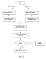
- FIG. 1 A flow diagram illustrating a known Analogue to Digital Converter ion detector system is shown in Fig. 1 .
- An input transient signal resulting from a trigger event is digitised and converted into arrival time and intensity pairs at the end of each transients predefined record length.
- a series of arrival time and intensity pairs are combined with those of other mass spectra within a predefined integration period or scan time to form a single mass spectrum.
- Each mass spectrum may comprise many tens of thousands of transients.
- a significant disadvantage of the known method is that it has a limited dynamic range and at relatively high signal intensities the Analogue to Digital Converter will suffer from saturation effects. It is also difficult to determine with any certainty whether or not the signal within an individual transient has saturated the Analogue to Digital Converter especially if the input signal changes significantly in intensity during the scan time. This frequently occurs, for example, on the leading or falling edge of an eluting LC peak. This can lead to inaccuracies in mass measurement and quantitation which are difficult to detect in the final data set.
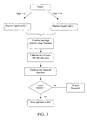
- a single transient signal output from the ion detector is preferably converted into two transient signals.
- the first transient signal is preferably amplified by or with a first voltage gain A and the second transient signal is preferably amplified by or with a second voltage gain of B.
- the first voltage gain A is preferably greater than the second voltage gain B (i.e. A > B).
- the second voltage gain B may be greater than the first voltage gain A.
- the two transient signals are then preferably digitised using two Analogue to Digital Converters.
- the lower gain (B) may be set 25 times lower.
- the two resulting digitised transients are then preferably processed to determine the arrival time (or mass or mass to charge ratio) and intensity of all detected ion arrival events.
- two lists of ion arrival times (or mass or mass to charge ratio) and corresponding intensity values are produced.
- this preferably involves an event detection step to identify regions relating to ion arrival events followed by a centroid measurement of the arrival time (or mass or mass to charge ratio) and corresponding intensity.
- Other methods of ion arrival event measurement and evaluation may be employed.
- each of the high gain transient digitised samples in the region of an ion arrival event being processed is preferably checked to see whether the Analogue to Digital Converter is suffering from saturation. For example, for an 8 bit Analogue to Digital Converter the output may be checked for values equal to 255. If the result of this check is TRUE, then the arrival time (or mass or mass to charge ratio) and corresponding intensity values for this event are preferably marked or tagged (by setting a bit associated with the registered event). The result is, in this example, two lists of events with high gain transient events that have saturated data embedded within them being tagged or flagged.
- ion arrival events which have been recorded wherein the Analogue to Digital Converter suffers from saturation are preferably identified and replaced with the corresponding event or events as recorded in the low gain transient list by scaling the intensity by the appropriate gain ratio A/B (or B/A). There may be more than one event in the low gain data which corresponds to a single saturated event in the high gain data.
- the preferred embodiment preferably results in a list of arrival time (or mass or mass to charge ratio) and intensity pairs having a higher dynamic range than either of the two original arrival time (or mass or mass to charge ratio) and intensity pair lists.
- the high dynamic range list may be combined with corresponding lists or data obtained from previous transients using a known method.
- Other less preferred methods of combining the transient signal event data may be employed.
- a histogram approach may be employed.
- detector signals may be monitored at more than one point in a dynode chain or in the case of a detector employing a dynode strip the signal may be monitored at various positions or locations along the dynode strip.
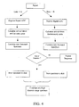
- Fig. 3 An arrangement outside the scope of the claims is shown in Fig. 3 .
- the signal from the ion detector is preferably split and amplified according to the method described above.
- the two transients are preferably combined to form a single high dynamic range transient.
- the high dynamic range transient is then preferably processed in order to produce a single list of events comprising arrival time (or mass or mass to charge ratio) and intensity pairs.
- the list of arrival time (or mass or mass to charge ratio) and intensity pairs is then preferably combined with other corresponding transient data as described above to form a summed spectrum.
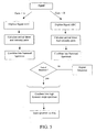
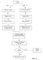
- Fig. 4 shows an arrangement in which two transient data streams are preferably kept separate throughout the process and are both preferably written to disk on a scan by scan basis. A high dynamic range spectrum is then preferably constructed by combining the two transient data streams as a post processing operation.
- This method has the slight disadvantage that the potential of high speed parallel processing which is potentially afforded by fast Field-Programmable Gate Array (FPGA) devices is not fully utilised.
- FPGA Field-Programmable Gate Array
- Fig. 5 shows an arrangement which more fully utilises the fast processing capabilities of Field-Programmable Gate Array devices. According to this arrangement an improvement in performance relative to the arrangement described above with reference to Fig. 4 is preferably observable.
- both methods have the slight disadvantage that it may be difficult to determine at what point saturation effects occur.
- a detector signal may be processed that changes from a low ion arrival rate for the first half of an integration period or scan to a high ion arrival rate (thereby saturating the Analogue to Digital Converter) for the remainder. Examination just of the average ion arrival rate may suggest that the high gain data does not suffer from saturation effects whereas in fact the high gain data may suffer from saturation effects and will result in corrupted data.
- non-linear analogue or amplifier processing stages are preferably provided prior to digitisation.
- the gain associated with these stages may, for example, comprise an intensity dependent gain (e.g. as in a logarithmic amplifier) or an intensity switched gain.
- the gain may reduce when the input signal exceeds a given threshold value and may increase when the signal falls below a given value.
- the gain switch may be registered by a processing Field-Programmable Gate Array.
- the changes induced by the non-linear stages are preferably reversed.
- the antilog of the digitised transient may be calculated.
- the digitised transient may be multiplied or divided by an appropriate factor when the gain was determined to switch.
- a person skilled in the art may construct other advantageous non-linear analogue blocks.
- Reversing the gain changes imposed by non-linear amplification prior to combining individual transient signals has advantages over performing this operation on the final spectrum produced at the end of a scan period particularly for situations where the average ion arrival rate changes during the scan period as previously described.
Description
- The present invention relates to a mass spectrometer and a method of mass spectrometry. The preferred embodiment relates to an ion detector system and method of detecting ions.
- It is known to use Time to Digital Converters ("TDC") and Analogue to Digital Converters ("ADC") as part of data recording electronics for many analytical instruments including Time of Flight mass spectrometers.
- Time of Flight instruments incorporating Time to Digital Converters are known wherein signals resulting from ions arriving at an ion detector are recorded. Signals which satisfy defined detection criteria are recorded as a single binary value and are associated with a particular arrival time relative to a trigger event. A fixed amplitude threshold may be used to trigger recording of an ion arrival event. Ion arrival events which are subsequently recorded resulting from subsequent trigger events are combined to form a histogram of ion arrival events. The histogram of ion arrival events is then presented as a spectrum for further processing. Time to Digital Converters have the advantage of being able to detect relatively weak signals so long as the probability of multiple ions arriving at the ion detector in close temporal proximity remains relatively low. One disadvantage of Time to Digital Converters is that once an ion event has been recorded then there is a significant time interval or dead-time following the ion arrival event during which time no further ion arrival events can be recorded.
- Another important disadvantage of Time to Digital Converters is that they are unable to distinguish between a signal resulting from the arrival of a single ion at the ion detector and a signal resulting from the simultaneous arrival of multiple ions at the ion detector. This is due to the fact that the signal will only cross the threshold once irrespective of whether a single ion arrived at the ion detector or whether multiple ions arrived simultaneously at the ion detector. Both situations result in only a single ion arrival event being recorded.
- At relatively high signal intensities the above mentioned disadvantages coupled with the problem of dead-time effects will result in a significant number of ion arrival events failing to be recorded and/or an incorrect number of ions being recorded. This will result in an inaccurate representation of the signal intensity and an inaccurate measurement of the ion arrival time. These effects have the result of limiting the dynamic range of the ion detector system.
- Time of Flight instruments which incorporate Analogue to Digital Converters are also known. An Analogue to Digital Converter is arranged to digitise signals resulting from ions arriving at the ion detector relative to a trigger event. The digitised signals resulting from subsequent trigger events are summed or averaged to produce a spectrum for further processing. A known signal averager is capable of digitising the output from ion detector electronics at a frequency of 3-4 GHz with eight or ten bit intensity resolution.
- One advantage of using an Analogue to Digital Converter as part of an ion detector system is that multiple ions which arrive substantially simultaneously at an ion detector and at relatively high signal intensities can be recorded without the ion detector suffering from distortion or saturation effects. However, the detection of low intensity signals is generally limited by electronic noise from the digitiser electronics, the ion detector and the amplifier system. The problem of electronic noise also effectively limits the dynamic range of the ion detector system.
- Another disadvantage of using an Analogue to Digital Converter as part of an ion detector system (as opposed to using a Time to Digital Converter as part of the ion detector system) is that the analogue width of the signal generated by a single ion adds to the width of the ion arrival envelope for a particular mass to charge value in the final spectrum. In the case of a Time to Digital Converter, only ion arrival times are recorded and hence the width of mass peaks in the final spectrum is determined only by the spread in ion arrival times for each mass peak and by variation in the voltage pulse height produced by an ion arrival relative to the signal threshold.
- It is known to attempt to extend the dynamic range of both Time to Digital Converter based ion detector systems and Analogue to Digital Converter based ion detector systems by switching the transmission of the spectrometer prior to the ion detector. However, these methods have the disadvantage of having a reduced duty cycle.
- Another way of attempting to extend the dynamic range of both Time to Digital Converter and Analogue to Digital Converter based ion detector systems is to use an ion detector having multiple anodes which are different sizes. However, such an approach is difficult to implement and the ion detector system can suffer from cross-talk between the anodes.
- A method of increasing the dynamic range of a transient recorder by using two Analogue to Digital Converters is known. A transient signal from an ion detector is amplified using two amplifiers having different gains. The two transients are digitized and the digitized data is combined on a time sample by time sample basis. High gain samples are used unless saturation is determined to occur at which point low gain data is substituted. The low gain data is scaled by the difference in gain between the two amplifiers. The result is a combined transient having a higher dynamic range than that obtainable using a single Analogue to Digital Converter. The combined transient is added to other transients which were collected previously using a known averager method. Once a preset number of transients have been averaged the resulting spectrum is stored to disk. See
US-2006/0020400-A for an example of a detector with increased dynamic range. - There are, however, certain disadvantages inherent with the known technique. Any errors in the gain of the amplifiers of the Analogue to Digital Converter input stages or DC offsets (amplifier or Analogue to Digital Converter) or signal synchronisation of the Analogue to Digital Converters relative to the trigger event can result in significant shifts in arrival time when the data from both Analogue to Digital Converters is combined. Synchronisation between the two signals presented to the Analogue to Digital Converters is difficult to achieve at high frequencies of digitisation and attempts at correcting any time differences in the signal being digitised is, in effect, limited to one digitisation time interval which may be too coarse to be of any particular use.
- The known method also suffers from the same problems as a standard averaging Analogue to Digital Converter system in terms of reduced dynamic range due to the averaging of noise at low signal intensities and degraded resolution due to the digitization of the analogue ion peak width.
- Detectors using a combination of both Time to Digital Converter electronics and Analogue to Digital Converter electronics have been employed in an attempt to take advantage of the characteristics of each different type of recording device thereby attempting to increase the dynamic range and the observed time or mass resolution. However, such systems are relatively complex to calibrate and operate. Such systems are also comparatively expensive. See
US-2002/0175292-A for an example of a multiple detection system. - Recent improvements in the speed of digital processing devices have allowed the production of ion detection systems which seek to exploit the various different advantageous features of both Time to Digital Converter systems and Analogue to Digital Converter systems. Digitised transient signals are converted into arrival time and intensity pairs. The arrival time and intensity pairs from each transient are combined over a scan period into a mass spectrum. Each mass spectrum may comprise tens of thousands of transients. The resulting spectrum has the advantage in terms of resolution of Time to Digital Converter systems (i.e. the analogue peak width of an ion arrival does not contribute significantly to the final peak width of the spectrum). Furthermore, the system is able to record signal intensities which result from multiple simultaneous ion arrival events of the Analogue to Digital Converter. In addition, discrimination against electronic noise during detection of the individual time or mass intensity pairs virtually eliminates any electronic noise which would otherwise be present in the averaged data thereby increasing the dynamic range. However, although this technique does represent an improvement over previous known methods, It still suffers from a relatively limited dynamic range and at higher signal intensities it continues to suffer from saturation effects. In addition, it is difficult using the known method to know with any certainty whether the signal has at any time during the acquisition saturated the Analogue to Digital Converter especially if the input signal changes significantly in intensity during the time during which individual transients are being combined or integrated into a final spectrum (sometimes referred to as the scan time). This can lead to mass accuracy and quantitation errors which are difficult to detect and correct.
-
WO-2006/129094 discloses a mass spectrometer. - It is therefore desired to provide an improved ion detector system and an improved method of detecting ions.
- According to an aspect of the present invention there is provided a method of detecting ions as claimed in claim 1.
- The step of determining the first intensity and arrival time, mass or mass to charge ratio data preferably further comprises marking or flagging each peak in the first set of peaks when the maximum digitised signal within a peak is determined as equalling or approaching a maximum or full scale digitised output or is otherwise saturated or approaching saturation. The step of determining the second intensity and arrival time, mass or mass to charge ratio data preferably further comprises marking or flagging each peak in the second set of peaks when the maximum digitised signal within a peak is determined as equalling or approaching a maximum or full scale digitised output or is otherwise saturated or approaching saturation.
- The step of combining the first intensity and arrival time, mass or mass to charge ratio data and the second intensity and arrival time, mass or mass to charge ratio data preferably further comprises:
- (a) selecting peak intensity and arrival time, mass or mass to charge ratio data from the second set of peaks for each or at least some peaks which are not marked or flagged or otherwise indicated as suffering from or approaching saturation; and/or
- (b) selecting peak intensity and arrival time, mass or mass to charge ratio data from the first set of peaks when the nearest peak or a close peak having the nearest or a close arrival time in the second set of peaks is marked or flagged or otherwise indicated as suffering from or approaching saturation.
- The method preferably further comprises scaling the peaks selected from the first set of peaks by a scale factor. The scale factor preferably corresponds with, is close to or is otherwise related to the ratio of the second gain to the first gain.
- The method preferably further comprises summing the combined data set with a plurality of other corresponding combined data sets to form a final spectrum.
- There is also described a method of detecting ions comprising:
- outputting a first signal and a second signal from an ion detector, wherein the first signal corresponds with a signal multiplied or amplified by a first gain and the second signal corresponds with a signal multiplied or amplified by a second different gain;
- digitising the first signal to produce a first digitised signal and digitising the second signal to produce a second digitised signal;
- summing the first digitised signal with a plurality of other corresponding first digitised signals to form a first summed digitised signal;
- summing the second digitised signal with a plurality of other corresponding second digitised signals to form a second summed digitised signal;
- determining first summed intensity and arrival time, mass or mass to charge ratio data from the first summed digitised signal;
- determining second summed intensity and arrival time, mass or mass to charge ratio data from the second summed digitised signal; and
- combining the first summed intensity and arrival time, mass or mass to charge ratio data and the second summed intensity and arrival time, mass or mass to charge ratio data to form a final spectrum.
- The method preferably further comprises processing the first summed digitised signal to detect a first set of peaks or ion arrival events and/or processing the second summed digitised signal to detect a second set of peaks or ion arrival events.
- The step of determining the first summed intensity and arrival time, mass or mass to charge ratio data from the first summed digitised signal preferably further comprises determining first summed intensity and arrival time, mass or mass to charge ratio data for each or at least some peaks or ion arrival events in the first set of peaks or ion arrival events. The step of determining the second summed intensity and arrival time, mass or mass to charge ratio data from the second summed digitised signal preferably further comprises determining second summed intensity and arrival time, mass or mass to charge ratio data for each or at least some peaks or ion arrival events in the second set of peaks or ion arrival events.
- The step of determining the first summed intensity and arrival time, mass or mass to charge ratio data preferably further comprises marking or flagging each peak or ion arrival event in the first set of peaks or ion arrival events when the maximum digitised signal within a peak or ion arrival event is determined as equalling or approaching a maximum or full scale digitised output or is otherwise saturated or approaching saturation. The step of determining the second summed intensity and arrival time, mass or mass to charge ratio data preferably further comprises marking or flagging each peak or ion arrival event in the second set of peaks or ion arrival events when the maximum digitised signal within a peak or ion arrival event is determined as equalling or approaching a maximum or full scale digitised output or is otherwise saturated or approaching saturation.
- The step of combining the first summed intensity and arrival time, mass or mass to charge ratio data and the second summed intensity and arrival time, mass or mass to charge ratio data preferably further comprises:
- (a) selecting peak intensity and arrival time, mass or mass to charge ratio data from the second set of peaks or ion arrival events for each or at least some peaks or ion arrival events which are not marked or flagged or otherwise indicated as suffering from or approaching saturation; and/or
- (b) selecting peak intensity and arrival time, mass or mass to charge ratio data from the first set of peaks or ion arrival events when the nearest peak or a close peak or an ion arrival event having the nearest or a close arrival time in the second set of peaks or ion arrival events is marked or flagged or otherwise indicated as suffering from or approaching saturation.
- The method preferably further comprises scaling the peaks or ion arrival events selected from the first set of peaks or ion arrival events by a scale factor. The scale factor preferably corresponds with, is close to or is otherwise related to the ratio of the second gain to the first gain.
- There is also described a method of detecting ions comprising:
- outputting a first signal and a second signal from an ion detector, wherein the first signal corresponds with a signal multiplied or amplified by a first gain and the second signal corresponds with a signal multiplied or amplified by a second different gain;
- digitising the first signal to produce a first digitised signal and digitising the second signal to produce a second digitised signal;
- combining the first digitised signal and the second digitised signal to form a combined digitised signal;
- determining intensity and arrival time, mass or mass to charge ratio data from the combined digitised signal; and
- summing the intensity and arrival time, mass or mass to charge ratio data with a plurality of other corresponding intensity and arrival time, mass or mass to charge ratio data to form a final spectrum.
- The method preferably further comprises processing the combined digitised signal to detect a set of peaks or ion arrival events.
- The step of determining the intensity and arrival time, mass or mass to charge ratio data from the combined digitised signal preferably further comprises determining intensity and arrival time, mass or mass to charge ratio data for each or at least some peaks or ion arrival events in the set of peaks or ion arrival events.
- The step of determining the intensity and arrival time, mass or mass to charge ratio data preferably further comprises marking or flagging each peak or ion arrival event in the first digitised signal when the maximum digitised signal within a peak or ion arrival event is determined as equalling or approaching a maximum or full scale digitised output or is otherwise saturated or approaching saturation. The step of determining the intensity and arrival time, mass or mass to charge ratio data preferably further comprises marking or flagging each peak or ion arrival event in the second digitised signal when the maximum digitised signal within a peak or ion arrival event is determined as equalling or approaching a maximum or full scale digitised output or is otherwise saturated or approaching saturation.
- The step of combining the first digitised signal and the second digitised signal preferably further comprises:
- (a) selecting peak intensity and arrival time, mass or mass to charge ratio data from the second digitised signal for each or at least some peaks or ion arrival events which are not marked or flagged or otherwise indicated as suffering from or approaching saturation; and/or
- (b) selecting peak intensity and arrival time, mass or mass to charge ratio data from the first digitised signal when the nearest peak or a close peak or an ion arrival event having the nearest or a close arrival time in the second digitised signal is marked or flagged or otherwise indicated as suffering from or approaching saturation.
- The method preferably further comprises scaling the peaks or ion arrival events selected from the first digitised signal by a scale factor. The scale factor preferably corresponds with, is close to or is otherwise related to the ratio of the second gain to the first gain.
- There is also described a method of detecting ions comprising:
- outputting a first signal and a second signal from an ion detector, wherein the first signal corresponds with a signal multiplied or amplified by a first gain and the second signal corresponds with a signal multiplied or amplified by a second different gain;
- digitising the first signal to produce a first digitised signal and digitising the second signal to produce a second digitised signal;
- combining the first digitised signal and the second digitised signal to form a combined digitised signal;
- summing the combined digitised signal with a plurality of other corresponding combined digitised signals to form a final spectrum; and
- determining intensity and arrival time, mass or mass to charge ratio data from the final spectrum.
- The method preferably further comprises processing the final spectrum to detect a set of peaks or ion arrival events.
- The step of determining the intensity and arrival time, mass or mass to charge ratio data from the final spectrum preferably further comprises determining intensity and arrival time, mass or mass to charge ratio data for each or at least some peaks or ion arrival events in the set of peaks or ion arrival events.
- The step of determining the intensity and arrival time, mass or mass to charge ratio data preferably further comprises marking or flagging each peak or ion arrival event in the first digitised signal when the maximum digitised signal within a peak or ion arrival event is determined as equalling or approaching a maximum or full scale digitised output or is otherwise saturated or approaching saturation. The step of determining the intensity and arrival time, mass or mass to charge ratio data preferably further comprises marking or flagging each peak or ion arrival event in the second digitised signal when the maximum digitised signal within a peak or ion arrival event is determined as equalling or approaching a maximum or full scale digitised output or is otherwise saturated or approaching saturation.
- The step of combining the first digitised signal and the second digitised signal preferably further comprises:
- (a) selecting peak intensity and arrival time, mass or mass to charge ratio data from the second digitised signal for each or at least some peaks or ion arrival events which are not marked or flagged or otherwise indicated as suffering from or approaching saturation; and/or
- (b) selecting peak intensity and arrival time, mass or mass to charge ratio data from the first digitised signal when the nearest peak or a close peak or an ion arrival event having the nearest or a close arrival time in the second digitised signal is marked or flagged or otherwise indicated as suffering from or approaching saturation.
- The method preferably further comprises scaling the peaks or ion arrival events selected from the first digitised signal by a scale factor. The scale factor preferably corresponds with, is close to or is otherwise related to the ratio of the second gain to the first gain.
- There is also described a method of detecting ions comprising:
- outputting a first signal and a second signal from an ion detector, wherein the first signal corresponds with a signal multiplied or amplified by a first gain and the second signal corresponds with a signal multiplied or amplified by a second different gain;
- digitising the first signal to produce a first digitised signal and digitising the second signal to produce a second digitised signal;
- determining first intensity and arrival time, mass or mass to charge ratio data from the first digitised signal;
- determining second intensity and arrival time, mass or mass to charge ratio data from the second digitised signal;
- summing the first intensity and arrival time, mass or mass to charge ratio data with a plurality of other corresponding first intensity and arrival time, mass or mass to charge ratio data to form a first summed spectrum;
- summing the second intensity and arrival time, mass or mass to charge ratio data with a plurality of other corresponding second intensity and arrival time, mass or mass to charge ratio data to form a second summed spectrum; and
- combining the first summed spectrum and the second summed spectrum to form a final spectrum.
- The method preferably further comprises processing the first digitised signal to detect a first set of peaks or ion arrival events and/or processing the second digitised signal to detect a second set of peaks or ion arrival events.
- The step of determining the first intensity and arrival time, mass or mass to charge ratio data from the first digitised signal preferably further comprises determining intensity and arrival time, mass or mass to charge ratio data for each or at least some peaks or ion arrival events in the first set of peaks or ion arrival events. The step of determining the second intensity and arrival time, mass or mass to charge ratio data from the second digitised signal preferably further comprises determining intensity and arrival time, mass or mass to charge ratio data for each or at least some peaks or ion arrival events in the second set of peaks or ion arrival events.
- The step of determining the first intensity and arrival time, mass or mass to charge ratio data preferably further comprises marking or flagging each peak or ion arrival event in the first set of peaks or ion arrival events when the maximum digitised signal within a peak or ion arrival event is determined as equalling or approaching a maximum or full scale digitised output or is otherwise saturated or approaching saturation. The step of determining the second intensity and arrival time, mass or mass to charge ratio data preferably further comprises marking or flagging each peak or ion arrival event in the second set of peaks or ion arrival events when the maximum digitised signal within a peak or ion arrival event is determined as equalling or approaching a maximum or full scale digitised output or is otherwise saturated or approaching saturation.
- The step of combining the first summed spectrum and the second summed spectrum to form a final spectrum preferably further comprises:
- (a) selecting peak intensity and arrival time, mass or mass to charge ratio data from the second summed spectrum for each or at least some peaks or ion arrival events which are not marked or flagged or otherwise indicated as suffering from or approaching saturation; and/or
- (b) selecting peak intensity and arrival time, mass or mass to charge ratio data from the first summed spectrum when the nearest peak or a close peak or an ion arrival event having the nearest or a close arrival time in the second summed spectrum is marked or flagged or otherwise indicated as suffering from or approaching saturation.
- The method preferably further comprises scaling the peaks or ion arrival events selected from the first summed spectrum by a scale factor. The scale factor preferably corresponds with, is close to or is otherwise related to the ratio of the second gain to the first gain.
- There is also described a method of detecting ions comprising:
- outputting a first signal and a second signal from an ion detector, wherein the first signal corresponds with a signal multiplied or amplified by a first gain and the second signal corresponds with a signal multiplied or amplified by a second different gain;
- digitising the first signal to produce a first digitised signal and digitising the second signal to produce a second digitised signal;
- summing the first digitised signal with a plurality of other corresponding first digitised signals to form a first summed digital signal;
- summing the second digitised signal with a plurality of other corresponding second digitised signals to form a second summed digital signal;
- determining first summed intensity and arrival time, mass or mass to charge ratio data from the first summed digital signal;
- determining second summed intensity and arrival time, mass or mass to charge ratio data from the second summed digital signal; and
- combining the first summed intensity and arrival time, mass or mass to charge ratio data from the first summed digital signal and the second summed intensity and arrival time, mass or mass to charge ratio data from the second summed digital signal to produce a final spectrum.
- The method preferably further comprises processing the first digitised signal to detect a first set of peaks or ion arrival events and/or processing the second digitised signal to detect a second set of peaks or ion arrival events.
- The step of determining the first summed intensity and arrival time, mass or mass to charge ratio data from the first summed digitised signal preferably further comprises determining intensity and arrival time, mass or mass to charge ratio data for each or at least some peaks or ion arrival events in the first set of peaks or ion arrival events. The step of determining the second summed intensity and arrival time, mass or mass to charge ratio data from the second summed digitised signal preferably further comprises determining intensity and arrival time, mass or mass to charge ratio data for each or at least some peaks or ion arrival events in the second set of peaks or ion arrival events.
- The step of determining the first summed intensity and arrival time, mass or mass to charge ratio data preferably further comprises marking or flagging each peak or ion arrival event in the first set of peaks or ion arrival events when the maximum digitised signal within a peak or ion arrival event is determined as equalling or approaching a maximum or full scale digitised output or is otherwise saturated or approaching saturation. The step of determining the second summed intensity and arrival time, mass or mass to charge ratio data preferably further comprises marking or flagging each peak or ion arrival event in the second set of peaks or ion arrival events when the maximum digitised signal within a peak or ion arrival event is determined as equalling or approaching a maximum or full scale digitised output or is otherwise saturated or approaching saturation.
- The step of combining the first summed spectrum and the second summed spectrum to form a final spectrum preferably further comprises:
- (a) selecting peak intensity and arrival time, mass or mass to charge ratio data from the second summed spectrum for each or at least some peaks or ion arrival events which are not marked or flagged or otherwise indicated as suffering from or approaching saturation; and/or
- (b) selecting peak intensity and arrival time, mass or mass to charge ratio data from the first summed spectrum when the nearest peak or a close peak or an ion arrival event having the nearest or a close arrival time in the second summed spectrum is marked or flagged or otherwise indicated as suffering from or approaching saturation.
- The method preferably further comprises scaling the peaks or ion arrival events selected from the first summed spectrum by a scale factor. The scale factor preferably corresponds with, is close to or is otherwise related to the ratio of the second gain to the first gain.
- According to an embodiment of the present invention the method further comprises either:
- (a) applying a linear correction to the first digitised signal and/or applying a linear correction to the second digitised signal; and/or
- (b) applying a linear correction to the first digitised signal prior to the step of determining first intensity and arrival time, mass or mass to charge ratio data from the first digitised signal and/or applying a linear correction to the second digitised signal prior to the step of determining second intensity and arrival time, mass or mass to charge ratio data from the second digitised signal. Other embodiments are contemplated comprising applying a linear correction to a combined digitised signal.
- The step of outputting a first signal and a second signal comprises converting, splitting or dividing a signal output from an ion detector into a first signal and a second signal. The first and second signals are then multiplied or amplified by different gains. According to an embodiment outside the scope of the claims, the step of outputting the first signal and the second signal may comprise monitoring or outputting the signal from an ion detector at least two different positions or locations in or along one or more dynodes or another part of an ion detector.
- The first gain may be substantially greater than the second gain or more preferably the second gain may be substantially greater than the first gain.
- According to an embodiment the ratio of the first gain to the second gain is preferably selected from the group consisting of: (i) < 2; (ii) 2-5; (iii) 5-10; (iv) 10-15; (v) 15-20; (vi) 20-25; (vii) 25-30; (viii) 30-35; (ix) 35-40; (x) 40-45; (xi) 45-50; (xii) 50-60; (xiii) 60-70; (xiv) 70-80; (xv) 80-90; (xvi) 90-100; and (xvii) > 100. According to the preferred embodiment the ratio of the second gain to the first gain is preferably selected from the group consisting of: (i) < 2; (ii) 2-5; (iii) 5-10; (iv) 10-15; (v) 15-20; (vi) 20-25; (vii) 25-30; (viii) 30-35; (ix) 35-40; (x) 40-45; (xi) 45-50; (xii) 50-60; (xiii) 60-70; (xiv) 70-80; (xv) 80-90; (xvi) 90-100; and (xvii) > 100.
- The steps of digitising the first signal and digitising the second signal are preferably performed substantially simultaneously.
- The step of digitising the first signal comprises using a first Analogue to Digital Converter and/or the step of digitising the second signal comprises using a second Analogue to Digital Converter. The first Analogue to Digital Converter and/or the second Analogue to Digital Converter are preferably arranged to convert an analogue voltage to a digital output. The first Analogue to Digital Converter and/or the second Analogue to Digital Converter are preferably arranged to operate, in use, at a digitisation rate selected from the group consisting of: (i) < 1 GHz; (ii) 1-2 GHz; (iii) 2-3 GHz; (iv) 3-4 GHz; (v) 4-5 GHz; (vi) 5-6 GHz; (vii) 6-7 GHz; (viii) 7-8 GHz; (ix) 8-9 GHz; (x) 9-10 GHz; and (xi) > 10 GHz. The first Analogue to Digital Converter and/or the second Analogue to Digital Converter preferably comprise a resolution selected from the group consisting of: (i) at least 4 bits; (ii) at least 5 bits; (iii) at least 6 bits; (iv) at least 7 bits; (v) at least 8 bits; (vi) at least 9 bits; (vii) at least 10 bits; (viii) at least 11 bits; (ix) at least 12 bits; (x) at least 13 bits; (xi) at least 14 bits; (xii) at least 15 bits; and (xiii) at least 16 bits.
- The method preferably further comprises flagging data in the first digitised signal and/or the second digitised signal which is determined as corresponding to data which was obtained when an ion detector was saturated or nearing saturation.
- According to an embodiment the method further comprises either:
- (a) replacing at least part of the first digitised signal with at least part of the second digitised signal if it is determined that at least part of the first digitised signal suffers from saturation effects; and/or
- (b) replacing at least part of the second digitised signal with at least part of the first digitised signal if it is determined that at least part of the second digitised signal suffers from saturation effects.
- According to another aspect of the present invention there is provided a method of mass spectrometry comprising a method of detecting ions as claimed in any preceding claim.
- According to various embodiments of the present invention the method may comprise outputting a signal from an ion detector, wherein the signal is multiplied or amplified by a first gain to give the first (amplified) signal and outputting another signal which is multiplied or amplified by a second preferably higher gain to give the second (amplified) signal.
- According to another aspect of the present invention there is provided an ion detector system as claimed in claim 11.
- There is also described an ion detector system comprising:
- a device arranged and adapted to output a first signal and a second signal from an ion detector, wherein the first signal corresponds with a signal multiplied or amplified by a first gain and the second signal corresponds with a signal multiplied or amplified by a second different gain;
- a device arranged and adapted to digitise the first signal to produce a first digitised signal and a device arranged and adapted to digitise the second signal to produce a second digitised signal;
- a device arranged and adapted to sum the first digitised signal with a plurality of other corresponding first digitised signals to form a first summed digitised signal;
- a device arranged and adapted to sum the second digitised signal with a plurality of other corresponding second digitised signals to form a second summed digitised signal;
- a device arranged and adapted to determine first summed intensity and arrival time, mass or mass to charge ratio data from the first summed digitised signal;
- a device arranged and adapted to determine second summed intensity and arrival time, mass or mass to charge ratio data from the second summed digitised signal; and
- a device arranged and adapted to combine the first summed intensity and arrival time, mass or mass to charge ratio data and the second summed intensity and arrival time, mass or mass to charge ratio data to form a final spectrum.
- There is also described an ion detector system comprising:
- a device arranged and adapted to output a first signal and a second signal from an ion detector, wherein the first signal corresponds with a signal multiplied or amplified by a first gain and the second signal corresponds with a signal multiplied or amplified by a second different gain;
- a device arranged and adapted to digitise the first signal to produce a first digitised signal and a device arranged and adapted to digitise the second signal to produce a second digitised signal;
- a device arranged and adapted to combine the first digitised signal and the second digitised signal to form a combined digitised signal;
- a device arranged and adapted to determine intensity and arrival time, mass or mass to charge ratio data from the combined digitised signal; and
- a device arranged and adapted to sum the intensity and arrival time, mass or mass to charge ratio data with a plurality of other corresponding intensity and arrival time, mass or mass to charge ratio data to form a final spectrum.
- There is also described an ion detector system comprising:
- a device arranged and adapted to output a first signal and a second signal from an ion detector, wherein the first signal corresponds with a signal multiplied or amplified by a first gain and the second signal corresponds with a signal multiplied or amplified by a second different gain;
- a device arranged and adapted to digitise the first signal to produce a first digitised signal and a device arranged and adapted to digitise the second signal to produce a second digitised signal;
- a device arranged and adapted to combine the first digitised signal and the second digitised signal to form a combined digitised signal;
- a device arranged and adapted to sum the combined digitised signal with a plurality of other corresponding combined digitised signals to form a final spectrum; and
- a device arranged and adapted to determine intensity and arrival time, mass or mass to charge ratio data from the final spectrum.
- There is also described an ion detector system comprising:
- a device arranged and adapted to output a first signal and a second signal from an ion detector, wherein the first signal corresponds with a signal multiplied or amplified by a first gain and the second signal corresponds with a signal multiplied or amplified by a second different gain;
- a device arranged and adapted to digitise the first signal to produce a first digitised signal and a device arranged and adapted to digitise the second signal to produce a second digitised signal;
- a device arranged and adapted to determine first intensity and arrival time, mass or mass to charge ratio data from the first digitised signal;
- a device arranged and adapted to determine second intensity and arrival time, mass or mass to charge ratio data from the second digitised signal;
- a device arranged and adapted to sum the first intensity and arrival time, mass or mass to charge ratio data with a plurality of other corresponding first intensity and arrival time, mass or mass to charge ratio data to form a first summed spectrum;
- a device arranged and adapted to sum the second intensity and arrival time, mass or mass to charge ratio data with a plurality of other corresponding second intensity and arrival time, mass or mass to charge ratio data to form a second summed spectrum; and
- a device arranged and adapted to combine the first summed spectrum and the second summed spectrum to form a final spectrum.
- There is also described an ion detector system comprising:
- a device arranged and adapted to output a first signal and a second signal from an ion detector, wherein the first signal corresponds with a signal multiplied or amplified by a first gain and the second signal corresponds with a signal multiplied or amplified by a second different gain;
- a device arranged and adapted to digitise the first signal to produce a first digitised signal and a device arranged and adapted to digitise the second signal to produce a second digitised signal;
- a device arranged and adapted to sum the first digitised signal with a plurality of other corresponding first digitised signals to form a first summed digital signal;
- a device arranged and adapted to sum the second digitised signal with a plurality of other corresponding second digitised signals to form a second summed digital signal;
- a device arranged and adapted to determine first intensity and arrival time, mass or mass to charge ratio data from the first summed digital signal;
- a device arranged and adapted to determine second intensity and arrival time, mass or mass to charge ratio data from the second summed digital signal; and
- a device arranged and adapted to combine the first intensity and arrival time, mass or mass to charge ratio data from the first summed digital signal and the second intensity and arrival time, mass or mass to charge ratio data from the second summed digital signal to produce a final spectrum.
- According to another aspect of the present invention there is provided a mass spectrometer comprising an ion detector system as described above.
- The mass spectrometer preferably further comprises either:
- (a) an ion source arranged upstream of the ion detector system, wherein the ion source is selected from the group consisting of: (i) an Electrospray ionisation ("ESI") ion source; (ii) an Atmospheric Pressure Photo lonisation ("APPI") ion source; (iii) an Atmospheric Pressure Chemical lonisation ("APCI") ion source; (iv) a Matrix Assisted Laser Desorption lonisation ("MALDI") ion source; (v) a Laser Desorption Ionisation ("LDI") ion source; (vi) an Atmospheric Pressure lonisation ("API") ion source; (vii) a Desorption lonisation on Silicon ("DIOS") ion source; (viii) an Electron Impact ("EI") ion source; (ix) a Chemical lonisation ("CI") ion source; (x) a Field lonisation ("FI") ion source; (xi) a Field Desorption ("FD") ion source; (xii) an Inductively Coupled Plasma ("ICP") ion source; (xiii) a Fast Atom Bombardment ("FAB") ion source; (xiv) a Liquid Secondary Ion Mass Spectrometry ("LSIMS") ion source; (xv) a Desorption Electrospray lonisation ("DESI") ion source; (xvi) a Nickel-63 radioactive ion source; (xvii) an Atmospheric Pressure Matrix Assisted Laser Desorption lonisation ion source; and (xviii) a Thermospray ion source; and/or
- (b) one or more ion guides arranged upstream of the ion detector system; and/or
- (c) one or more ion mobility separation devices and/or one or more Field Asymmetric Ion Mobility Spectrometer devices arranged upstream of the ion detector system; and/or
- (d) one or more ion traps or one or more ion trapping regions arranged upstream of the ion detector system; and/or
- (e) a collision, fragmentation or reaction cell arranged upstream of the ion detector system, wherein the collision, fragmentation or reaction cell is selected from the group consisting of: (i) a Collisional Induced Dissociation ("CID") fragmentation device; (ii) a Surface Induced Dissociation ("SID") fragmentation device; (iii) an Electron Transfer Dissociation fragmentation device; (iv) an Electron Capture Dissociation fragmentation device; (v) an Electron Collision or Impact Dissociation fragmentation device; (vi) a Photo Induced Dissociation ("PID") fragmentation device; (vii) a Laser Induced Dissociation fragmentation device; (viii) an infrared radiation induced dissociation device; (ix) an ultraviolet radiation induced dissociation device; (x) a nozzle-skimmer interface fragmentation device; (xi) an in-source fragmentation device; (xii) an ion-source Collision Induced Dissociation fragmentation device; (xiii) a thermal or temperature source fragmentation device; (xiv) an electric field induced fragmentation device; (xv) a magnetic field induced fragmentation device; (xvi) an enzyme digestion or enzyme degradation fragmentation device; (xvii) an ion-ion reaction fragmentation device; (xviii) an ion-molecule reaction fragmentation device; (xix) an ion-atom reaction fragmentation device; (xx) an ion-metastable ion reaction fragmentation device; (xxi) an ion-metastable molecule reaction fragmentation device; (xxii) an ion-metastable atom reaction fragmentation device; (xxiii) an ion-ion reaction device for reacting ions to form adduct or product ions; (xxiv) an ion-molecule reaction device for reacting ions to form adduct or product ions; (xxv) an ion-atom reaction device for reacting ions to form adduct or product ions; (xxvi) an ion-metastable ion reaction device for reacting ions to form adduct or product ions; (xxvii) an ion-metastable molecule reaction device for reacting ions to form adduct or product ions; and (xxviii) an ion-metastable atom reaction device for reacting ions to form adduct or product ions; and/or
- (f) a mass analyser selected from the group consisting of: (i) a quadrupole mass analyser; (ii) a 2D or linear quadrupole mass analyser; (iii) a Paul or 3D quadrupole mass analyser; (iv) a Penning trap mass analyser; (v) an ion trap mass analyser; (vi) a magnetic sector mass analyser; (vii) Ion Cyclotron Resonance ("ICR") mass analyser; (viii) a Fourier Transform Ion Cyclotron Resonance ("FTICR") mass analyser; (ix) an electrostatic or orbitrap mass analyser; (x) a Fourier Transform electrostatic or orbitrap mass analyser; (xi) a Fourier Transform mass analyser; (xii) a Time of Flight mass analyser; (xiii) an orthogonal acceleration Time of Flight mass analyser; and (xiv) a linear acceleration Time of Flight mass analyser.
- According to an aspect of the present invention there is provided a mass spectrometer comprising an ion detector. The ion current arriving at the ion detector preferably varies in magnitude as a function of time. The output current from the ion detector is preferably passed to a voltage converter and amplifier. Two or more output voltages are preferably provided or output from the amplifier. Two or more Analogue to Digital Converters (ADCs) are preferably provided which preferably convert the two or more output voltages to digital outputs. Further processing of the digital outputs preferably produces one or more sets of data which preferably comprise time and intensity pairs (or mass or mass to charge ratio and intensity pairs).
- According to a preferred embodiment, each of the two or more digital outputs are preferably processed to produce sets of time and intensity pairs (or sets of mass or mass to charge ratio and intensity pairs). The sets of time and intensity pairs (or sets of mass or mass to charge ratio and intensity pairs) are preferably combined to yield a single set of time and intensity pairs (or a single set of mass or mass to charge ratio and intensity pairs) wherein the single set of data preferably has an increased dynamic range.
- According to an arrangement not in accordance with the invention the two digital outputs from the two Analogue to Digital Converters may be combined into a single digital output or transient having an increased dynamic range. The single digital output or transient is then preferably processed to produce a set of time and intensity pairs (or a set of mass or mass to charge ratio and intensity pairs). A multitude of corresponding sets of time and intensity pairs (or a multitude of sets of mass or mass to charge ratio and intensity pairs) are preferably combined to form a summed spectrum comprising time and intensity pairs (or mass or mass to charge ratio and intensity pairs).
- According to an arrangement not in accordance with the invention each of the two or more digital outputs may be processed to produce a first and second set of time and intensity pairs (or a first and second set of mass or mass to charge ratio and intensity pairs). A multitude of first sets of time and intensity pairs (or mass or mass to charge ratio and intensity pairs) are preferably combined to form a single combined set of first sets of time and intensity pairs (or mass or mass to charge ratio and intensity pairs). Likewise, a multitude of second sets of time and intensity pairs (or mass or mass to charge ratio and intensity pairs) are preferably combined to form a single combined set of second sets of time and intensity pairs (or mass or mass to charge ratio and intensity pairs). The first and second combined sets of time and intensity pairs (or mass or mass to charge ratio and intensity pairs) are preferably combined to yield a single combined set of time and intensity pairs (or mass or mass to charge ratio and intensity pairs) having an increased dynamic range.
- According to the preferred embodiment the ion current to voltage converter and the amplifier is preferably arranged to have a linear output voltage with respect to the input current. However, according to other less preferred embodiments the output voltage may vary in a substantially non-linear manner with respect to the input current and may, for example, be continuous or discontinuous. According to an embodiment the relationship between the output voltage and the input current may comprise a logarithmic function, a square function, a square root function, a power function, an exponential function, a stepped function or a function incorporating one or more linear functions and/or one or more non-linear functions and/or one or more step functions and/or any combination thereof.
- According to the preferred embodiment the mass spectrometer preferably comprises a Time of Flight mass spectrometer or mass analyser. However, other less preferred embodiments are contemplated wherein the mass spectrometer or mass analyser may comprise another type of mass spectrometer which provides an ion current that varies in magnitude as a function of time.
- According to the preferred embodiment the transient signal from the ion detector is preferably converted, split or output into two separate transient signals. The first transient signal is preferably amplified with or by a gain of A and the second transient signal is preferably amplified with or by a gain of B. According to an embodiment A > B. According to an alternative embodiment B > A. The two transient signals are preferably simultaneously digitised and processed to determine the arrival time (or mass or mass to charge ratio) and intensity of all of the ion events occurring. As a result two lists are preferably produced. During this processing sequence any event determined to include a digital sample that has an amplitude which saturates the Analogue to Digital Converter is preferably identified and flagged. The first list is preferably examined to select or identify any events determined to be suffering from saturation effects. If saturation is determined to have occurred then the event is preferably replaced with the arrival time and intensity of the corresponding event or events from the second transient with the intensity multiplied by the ratio of the two gains A/B (or B/A). The events in this combined list are preferably combined with those collected in or from previous or other transients. Once a predetermined number of transients has been collected and combined, the resultant combined spectrum is preferably transferred for storage to disk and the process is preferably repeated.
- Various embodiments of the present invention together with an arrangement given for illustrative purposes only will now be described, by way of example only, and with reference to the accompanying drawings in which:
-
Fig. 1 shows a flow diagram of a known Analogue to Digital Converter ion detection system; -
Fig. 2 shows a flow diagram illustrating a preferred embodiment of the present invention wherein a signal output from an ion detector is divided into two signals which are amplified by different gains, and wherein arrival time and intensity pairs are calculated for each digitised signal and the two sets of arrival time and intensity data are then combined to form a high dynamic range spectrum; -
Fig. 3 shows a flow diagram illustrating an arrangement not in accordance with the invention wherein two digitised signals are first combined to form a single transient and then time and intensity pairs are calculated for the single transient; -
Fig. 4 shows a flow diagram illustrating an arrangement not in accordance with the invention wherein first sets of arrival time and intensity pairs are summed to form a first summed spectrum and second sets of arrival time and intensity pairs are summed to form a second summed spectrum and wherein the first summed spectrum is then combined with the second summed spectrum; -
Fig. 5 shows a flow diagram illustrating an arrangement not in accordance with the invention wherein a first summed spectrum is combined with a second summed spectrum to form a high dynamic range spectrum; and -
Fig. 6 shows a flow diagram illustrating an embodiment of the present invention wherein a signal output from an ion detector is divided into two signals which are amplified by different gains and wherein two non-linear amplifier stages are provided prior to digitisation and wherein a non-linear conversion process is provided immediately after the digitisation stage. - A flow diagram illustrating a known Analogue to Digital Converter ion detector system is shown in
Fig. 1 . An input transient signal resulting from a trigger event is digitised and converted into arrival time and intensity pairs at the end of each transients predefined record length. A series of arrival time and intensity pairs are combined with those of other mass spectra within a predefined integration period or scan time to form a single mass spectrum. Each mass spectrum may comprise many tens of thousands of transients. - A significant disadvantage of the known method is that it has a limited dynamic range and at relatively high signal intensities the Analogue to Digital Converter will suffer from saturation effects. It is also difficult to determine with any certainty whether or not the signal within an individual transient has saturated the Analogue to Digital Converter especially if the input signal changes significantly in intensity during the scan time. This frequently occurs, for example, on the leading or falling edge of an eluting LC peak. This can lead to inaccuracies in mass measurement and quantitation which are difficult to detect in the final data set.
- An embodiment of the present invention will now be described with reference to
Fig. 2 . As shown inFig. 2 , according to the preferred embodiment a single transient signal output from the ion detector is preferably converted into two transient signals. The first transient signal is preferably amplified by or with a first voltage gain A and the second transient signal is preferably amplified by or with a second voltage gain of B. According to the preferred embodiment the first voltage gain A is preferably greater than the second voltage gain B (i.e. A > B). Alternatively, the second voltage gain B may be greater than the first voltage gain A. The two transient signals are then preferably digitised using two Analogue to Digital Converters. By way of example only, if two 8 bit Analogue to Digital Converters are used and if the amplifier with the highest gain (A) is chosen such that on average a single ion arrival results in a digitised signal that is 10 bits high, then the lower gain (B) may be set 25 times lower. - The two resulting digitised transients are then preferably processed to determine the arrival time (or mass or mass to charge ratio) and intensity of all detected ion arrival events. As a result, two lists of ion arrival times (or mass or mass to charge ratio) and corresponding intensity values are produced. According to the preferred embodiment this preferably involves an event detection step to identify regions relating to ion arrival events followed by a centroid measurement of the arrival time (or mass or mass to charge ratio) and corresponding intensity. Other methods of ion arrival event measurement and evaluation may be employed.
- According to an embodiment during the process of calculating or determining ion arrival times (or masses or mass to charge ratios) and determining the corresponding intensity, each of the high gain transient digitised samples in the region of an ion arrival event being processed is preferably checked to see whether the Analogue to Digital Converter is suffering from saturation. For example, for an 8 bit Analogue to Digital Converter the output may be checked for values equal to 255. If the result of this check is TRUE, then the arrival time (or mass or mass to charge ratio) and corresponding intensity values for this event are preferably marked or tagged (by setting a bit associated with the registered event). The result is, in this example, two lists of events with high gain transient events that have saturated data embedded within them being tagged or flagged. According to the preferred embodiment ion arrival events which have been recorded wherein the Analogue to Digital Converter suffers from saturation are preferably identified and replaced with the corresponding event or events as recorded in the low gain transient list by scaling the intensity by the appropriate gain ratio A/B (or B/A). There may be more than one event in the low gain data which corresponds to a single saturated event in the high gain data. The preferred embodiment preferably results in a list of arrival time (or mass or mass to charge ratio) and intensity pairs having a higher dynamic range than either of the two original arrival time (or mass or mass to charge ratio) and intensity pair lists.
- According to the preferred embodiment the high dynamic range list may be combined with corresponding lists or data obtained from previous transients using a known method. Other less preferred methods of combining the transient signal event data may be employed. For example, a histogram approach may be employed. An advantage of applying a conventional combine method is that it is relatively simple to apply a time offset that is a fraction of the digitisation step time to the arrival times accounting for any trigger time differences between the two Analogue to Digital Converters. Such trigger time differences may be caused by differences in propagation times.
- Other methods of converting the output of an ion arrival event at the detector into two or more signals with different gains may be used. For example, in the case of a discrete dynode, detector signals may be monitored at more than one point in a dynode chain or in the case of a detector employing a dynode strip the signal may be monitored at various positions or locations along the dynode strip.
- An arrangement outside the scope of the claims is shown in
Fig. 3 . According to this arrangement the signal from the ion detector is preferably split and amplified according to the method described above. After digitisation, the two transients are preferably combined to form a single high dynamic range transient. The high dynamic range transient is then preferably processed in order to produce a single list of events comprising arrival time (or mass or mass to charge ratio) and intensity pairs. The list of arrival time (or mass or mass to charge ratio) and intensity pairs is then preferably combined with other corresponding transient data as described above to form a summed spectrum. -
Fig. 4 shows an arrangement in which two transient data streams are preferably kept separate throughout the process and are both preferably written to disk on a scan by scan basis. A high dynamic range spectrum is then preferably constructed by combining the two transient data streams as a post processing operation. This method has the slight disadvantage that the potential of high speed parallel processing which is potentially afforded by fast Field-Programmable Gate Array (FPGA) devices is not fully utilised. -
Fig. 5 shows an arrangement which more fully utilises the fast processing capabilities of Field-Programmable Gate Array devices. According to this arrangement an improvement in performance relative to the arrangement described above with reference toFig. 4 is preferably observable. However, both methods have the slight disadvantage that it may be difficult to determine at what point saturation effects occur. For example, a detector signal may be processed that changes from a low ion arrival rate for the first half of an integration period or scan to a high ion arrival rate (thereby saturating the Analogue to Digital Converter) for the remainder. Examination just of the average ion arrival rate may suggest that the high gain data does not suffer from saturation effects whereas in fact the high gain data may suffer from saturation effects and will result in corrupted data. This is not the case according to the preferred embodiment as described above with relation toFig. 2 whereby each transient is preferably tested for saturation to avoid corrupting the output spectrum. However, both of these methods have the advantage over the arrangement described above in relation toFig. 3 in that any differences between the Analogue to Digital Converter trigger times can be corrected for. - A modification of the preferred embodiment described above with reference to
Fig. 2 is shown inFig. 6 . According to this embodiment one or more non-linear analogue or amplifier processing stages are preferably provided prior to digitisation. The gain associated with these stages may, for example, comprise an intensity dependent gain (e.g. as in a logarithmic amplifier) or an intensity switched gain. For example, the gain may reduce when the input signal exceeds a given threshold value and may increase when the signal falls below a given value. The gain switch may be registered by a processing Field-Programmable Gate Array. After digitisation, the changes induced by the non-linear stages are preferably reversed. For example, in the case of a logarithmic amplifier the antilog of the digitised transient may be calculated. In the switched gain example the digitised transient may be multiplied or divided by an appropriate factor when the gain was determined to switch. A person skilled in the art may construct other advantageous non-linear analogue blocks. - Reversing the gain changes imposed by non-linear amplification prior to combining individual transient signals has advantages over performing this operation on the final spectrum produced at the end of a scan period particularly for situations where the average ion arrival rate changes during the scan period as previously described.
- Although the embodiments shown and described above with reference to
Figs. 2 and6 show two separate amplifiers and digitising Analogue to Digital Converters other embodiments are contemplated wherein three, four, or more than four separate amplifiers and digitising Analogue to Digital Converters may be provided. - Although the present invention has been described with reference to preferred embodiments, it will be understood by those skilled in the art that various changes in form and detail may be made without departing from the scope of the invention as set forth in the accompanying claims.
Claims (13)
- A method of detecting ions comprising:outputting a first signal and a second signal from an ion detector, wherein said step of outputting said first signal and said second signal comprises converting, splitting or dividing a signal output from an ion detector Into said first signal and said second signal, wherein said first signal corresponds with a signal multiplied or amplified by a first gain and said second signal corresponds with a signal multiplied or amplified by a second different gain: anddigitising said first signal using a first Analogue to Digital Converter to produce a first digitised signal and digitising said second signal using a second Analogue to Digital Converter to produce a second digitised signal; characterised by:determining first intensity and arrival time, mass or mass to charge ratio data from said first digitised signal, wherein the step of determining said first intensity and arrival time, mass or mass to charge ratio data further comprises processing said first digitised signal to detect a first set of peaks and determining first intensity and arrival time, mass or mass to charge ratio data for each or at least some peaks in said first set of peaks;determining second intensity and arrival time, mass or mass to charge ratio data from said second digitised signal, wherein the step of determining said second intensity and arrival time, mass or mass to charge ratio data further comprises processing said second digitised signal to detect a second set of peaks and determining second intensity and arrival time, mass or mass to charge ratio data for each or at least some peaks in said second set of peaks;combining said first intensity and arrival time, mass or mass to charge ratio data and said second intensity and arrival time, mass or mass to charge ratio data to form a combined data set.
- A method as claimed in claim 1, wherein:(a) said step of determining said first intensity and arrival time, mass or mass to charge ratio data further comprises marking or flagging each peak in said first set of peaks when the maximum digitised signal within a peak is determined as equalling or approaching a maximum or full scale digitised output or is otherwise saturated or approaching saturation; and/or(b) said step of determining said second intensity and arrival time, mass or mass to charge ratio data further comprises marking or flagging each peak in said second set of peaks when the maximum digitised signal within a peak is determined as equalling or approaching a maximum or full scale digitised output or is otherwise saturated or approaching saturation.
- A method as claimed in claim 2, wherein said step of combining said first intensity and arrival time, mass or mass to charge ratio data and said second intensity and arrival time, mass or mass to charge ratio data further comprises:(a) selecting peak intensity and arrival time, mass or mass to charge ratio data from said second set of peaks for each or at least some peaks which are not marked or flagged or otherwise indicated as suffering from or approaching saturation: and/or(b) selecting peak intensity and arrival time, mass or mass to charge ratio data from said first set of peaks when the nearest peak or a close peak having the nearest or a close arrival time in said second set of peaks is marked or flagged or otherwise indicated as suffering from or approaching saturation.
- A method as claimed in claim 3, further comprising scaling said peaks selected from said first set of peaks by a scale factor.
- A method as claimed in claim 4, wherein said scale factor corresponds with, is close to or is otherwise related to the ratio of said second gain to said first gain.
- A method as claimed in any preceding claim, further comprising summing said combined data set with a plurality of other corresponding combined data sets to form a final spectrum.
- A method as claimed in any preceding claim, wherein either:(a) said first gain is substantially greater than said second gain; or(b) said second gain is substantially greater than said first gain.
- A method as claimed in any preceding claim, further comprising flagging data in said first digitised signal and/or said second digitised signal which is determined as corresponding to data which was obtained when an ion detector was saturated or nearing saturation.
- A method as claimed in any preceding claim, further comprising either:(a) replacing at least part of said first digitised signal with at least part of said second digitised signal if it is determined that at least part of said first digitised signal suffers from saturation effects; and/or(b) replacing at least part of said second digitised signal with at least part of said first digitised signal if it is determined that at least part of said second digitised signal suffers from saturation effects.
- A method as claimed in any preceding claim, wherein prior to said step of digitising said first and second signals, one or more non-linear analogue or amplifier processing stages are provided to said first and second signals.
- A method as claimed in any preceding claim, further comprising either:(a) applying a linear correction to said first digitised signal and/or applying a linear correction to said second digitised signal; and/or(b) applying a linear correction to said first digitised signal prior to said step of determining first intensity and arrival time, mass or mass to charge ratio data from said first digitised signal and/or applying a linear correction to said second digitised signal prior to said step of determining second intensity and arrival time, mass or mass to charge ratio data from said second digitised signal.
- A method as claimed in claims 10 and 11, wherein said linear correction(s) reverse the changes imposed by said non-linear analogue or amplifier processing stages.
- An ion detector system comprising:a device arranged and adapted to convert, split or divide a signal output from an ion detector into a first signal and a second signal, wherein said first signal corresponds with a signal multiplied or amplified by a first gain and said second signal corresponds with a signal multiplied or amplified by a second different gain; anda first Analogue to Digital Converter arranged and adapted to digitise said first signal to produce a first digitised signal and a second Analogue to Digital Converter arranged and adapted to digitise said second signal to produce a second digitised signal; characterised in that said system further comprises:a device arranged and adapted to determine first intensity and arrival time, mass or mass to charge ratio data from said first digitised signal, wherein said determining said first intensity and arrival time, mass or mass to charge ratio data includes processing said first digitised signal to detect a first set of peaks and determining first intensity and arrival time, mass or mass to charge ratio data for each or at least some peaks in said first set of peaks;a device arranged and adapted to determine second intensity and arrival time, mass or mass to charge ratio data from said second digitised signal, wherein said determining said second Intensity and arrival time, mass or mass to charge ratio data includes processing said second digitised signal to detect a second set of peaks and determining second intensity and arrival time, mass or mass to charge ratio data for each or at least some peaks in said second set of peaks;a device arranged and adapted to combine said first intensity and arrival time, mass or mass to charge ratio data and said second intensity and arrival time, mass or mass to charge ratio data to form a combined data set.
Priority Applications (2)
| Application Number | Priority Date | Filing Date | Title |
|---|---|---|---|
| EP10000200A EP2184763B1 (en) | 2007-05-22 | 2008-05-22 | Mass spectrometer |
| EP11194978A EP2434526A1 (en) | 2007-05-22 | 2008-05-22 | Mass spectrometer |
Applications Claiming Priority (3)
| Application Number | Priority Date | Filing Date | Title |
|---|---|---|---|
| GB0709799A GB0709799D0 (en) | 2007-05-22 | 2007-05-22 | Mass spectrometer |
| US94621107P | 2007-06-26 | 2007-06-26 | |
| PCT/GB2008/001756 WO2008142418A2 (en) | 2007-05-22 | 2008-05-22 | Mass spectrometer |
Related Child Applications (2)
| Application Number | Title | Priority Date | Filing Date |
|---|---|---|---|
| EP10000200.5 Division-Into | 2010-01-12 | ||
| EP11194978.0 Division-Into | 2011-12-21 |
Publications (2)
| Publication Number | Publication Date |
|---|---|
| EP2156460A2 EP2156460A2 (en) | 2010-02-24 |
| EP2156460B1 true EP2156460B1 (en) | 2013-01-30 |
Family
ID=38234872
Family Applications (3)
| Application Number | Title | Priority Date | Filing Date |
|---|---|---|---|
| EP10000200A Active EP2184763B1 (en) | 2007-05-22 | 2008-05-22 | Mass spectrometer |
| EP11194978A Withdrawn EP2434526A1 (en) | 2007-05-22 | 2008-05-22 | Mass spectrometer |
| EP08750679A Active EP2156460B1 (en) | 2007-05-22 | 2008-05-22 | Mass spectrometer |
Family Applications Before (2)
| Application Number | Title | Priority Date | Filing Date |
|---|---|---|---|
| EP10000200A Active EP2184763B1 (en) | 2007-05-22 | 2008-05-22 | Mass spectrometer |
| EP11194978A Withdrawn EP2434526A1 (en) | 2007-05-22 | 2008-05-22 | Mass spectrometer |
Country Status (6)
| Country | Link |
|---|---|
| US (3) | US8354634B2 (en) |
| EP (3) | EP2184763B1 (en) |
| JP (1) | JP5528331B2 (en) |
| CA (1) | CA2687420C (en) |
| GB (2) | GB0709799D0 (en) |
| WO (1) | WO2008142418A2 (en) |
Families Citing this family (42)
| Publication number | Priority date | Publication date | Assignee | Title |
|---|---|---|---|---|
| GB0709799D0 (en) * | 2007-05-22 | 2007-06-27 | Micromass Ltd | Mass spectrometer |
| GB0909289D0 (en) | 2009-05-29 | 2009-07-15 | Micromass Ltd | Method of processing mass spectral data |
| IT1395787B1 (en) * | 2009-09-16 | 2012-10-19 | Dani Instr Spa | MASS SPECTROMETER WITH WIDE RANGE OF DYNAMICS. |
| DE102010056152A1 (en) * | 2009-12-31 | 2011-07-07 | Spectro Analytical Instruments GmbH, 47533 | Simultaneous inorganic mass spectrometer and inorganic mass spectrometry method |
| US9330892B2 (en) | 2009-12-31 | 2016-05-03 | Spectro Analytical Instruments Gmbh | Simultaneous inorganic mass spectrometer and method of inorganic mass spectrometry |
| JP5781545B2 (en) * | 2010-02-02 | 2015-09-24 | ディーエイチ テクノロジーズ デベロップメント プライベート リミテッド | Method and system for operating a time-of-flight mass spectrometry detection system |
| GB201002447D0 (en) * | 2010-02-12 | 2010-03-31 | Micromass Ltd | Mass spectrometer |
| DE102010011974B4 (en) | 2010-03-19 | 2016-09-15 | Bruker Daltonik Gmbh | Saturation correction for ion signals in time-of-flight mass spectrometers |
| US10074528B2 (en) * | 2010-12-17 | 2018-09-11 | Thermo Fisher Scientific (Bremen) Gmbh | Data acquisition system and method for mass spectrometry |
| GB201106689D0 (en) * | 2011-04-20 | 2011-06-01 | Micromass Ltd | Function switching with fast asynchronous acquisition |
| CN107086166B (en) * | 2011-06-03 | 2018-12-07 | Dh科技发展私人贸易有限公司 | It is scanned using variable window band-pass filter from measurement and removes ion to improve and scan interior dynamic range |
| GB201208841D0 (en) | 2012-05-18 | 2012-07-04 | Micromass Ltd | Calibrating dual adc acquisition system |
| GB201312266D0 (en) * | 2013-07-09 | 2013-08-21 | Micromass Ltd | Method of recording ADC saturation |
| US10354849B2 (en) * | 2013-07-09 | 2019-07-16 | Micromass Uk Limited | Method of recording ADC saturation |
| WO2015004457A1 (en) * | 2013-07-09 | 2015-01-15 | Micromass Uk Limited | Intelligent dynamic range enhancement |
| WO2015173562A1 (en) * | 2014-05-13 | 2015-11-19 | Micromass Uk Limited | Multi-dimensional ion separation |
| DE112015002758T5 (en) | 2014-06-11 | 2017-04-20 | Micromass Uk Limited | Marking of ADC coalescence |
| GB201410382D0 (en) * | 2014-06-11 | 2014-07-23 | Micromass Ltd | Flagging ADC coalescence |
| GB201514643D0 (en) * | 2015-08-18 | 2015-09-30 | Micromass Ltd | Mass Spectrometer data acquisition |
| GB201515357D0 (en) | 2015-08-28 | 2015-10-14 | Micromass Ltd | Mass spectrometer with digitial step attenuator |
| GB2544959B (en) * | 2015-09-17 | 2019-06-05 | Thermo Fisher Scient Bremen Gmbh | Mass spectrometer |
| US10026598B2 (en) * | 2016-01-04 | 2018-07-17 | Rohde & Schwarz Gmbh & Co. Kg | Signal amplitude measurement and calibration with an ion trap |
| CN105609401B (en) * | 2016-02-17 | 2017-10-24 | 广州禾信分析仪器有限公司 | A kind of method and system for improving time-of-flight mass spectrometer dynamic detection range |
| US20170263426A1 (en) * | 2016-03-10 | 2017-09-14 | Leco Corporation | Dynamic Baseline Adjuster |
| GB201613988D0 (en) | 2016-08-16 | 2016-09-28 | Micromass Uk Ltd And Leco Corp | Mass analyser having extended flight path |
| GB201618023D0 (en) | 2016-10-25 | 2016-12-07 | Micromass Uk Limited | Ion detection system |
| GB2567794B (en) | 2017-05-05 | 2023-03-08 | Micromass Ltd | Multi-reflecting time-of-flight mass spectrometers |
| GB2563571B (en) | 2017-05-26 | 2023-05-24 | Micromass Ltd | Time of flight mass analyser with spatial focussing |
| WO2019030472A1 (en) | 2017-08-06 | 2019-02-14 | Anatoly Verenchikov | Ion mirror for multi-reflecting mass spectrometers |
| EP3662503A1 (en) | 2017-08-06 | 2020-06-10 | Micromass UK Limited | Ion injection into multi-pass mass spectrometers |
| US11049712B2 (en) | 2017-08-06 | 2021-06-29 | Micromass Uk Limited | Fields for multi-reflecting TOF MS |
| EP3662502A1 (en) | 2017-08-06 | 2020-06-10 | Micromass UK Limited | Printed circuit ion mirror with compensation |
| US11817303B2 (en) | 2017-08-06 | 2023-11-14 | Micromass Uk Limited | Accelerator for multi-pass mass spectrometers |
| US11081332B2 (en) | 2017-08-06 | 2021-08-03 | Micromass Uk Limited | Ion guide within pulsed converters |
| US11211238B2 (en) | 2017-08-06 | 2021-12-28 | Micromass Uk Limited | Multi-pass mass spectrometer |
| GB201806507D0 (en) | 2018-04-20 | 2018-06-06 | Verenchikov Anatoly | Gridless ion mirrors with smooth fields |
| GB201807626D0 (en) | 2018-05-10 | 2018-06-27 | Micromass Ltd | Multi-reflecting time of flight mass analyser |
| GB201807605D0 (en) | 2018-05-10 | 2018-06-27 | Micromass Ltd | Multi-reflecting time of flight mass analyser |
| GB201808530D0 (en) | 2018-05-24 | 2018-07-11 | Verenchikov Anatoly | TOF MS detection system with improved dynamic range |
| GB201810573D0 (en) | 2018-06-28 | 2018-08-15 | Verenchikov Anatoly | Multi-pass mass spectrometer with improved duty cycle |
| GB201901411D0 (en) | 2019-02-01 | 2019-03-20 | Micromass Ltd | Electrode assembly for mass spectrometer |
| GB202110412D0 (en) * | 2021-07-20 | 2021-09-01 | Micromass Ltd | Mass spectrometer for generating and summing mass spectral data |
Citations (2)
| Publication number | Priority date | Publication date | Assignee | Title |
|---|---|---|---|---|
| US20040084613A1 (en) * | 2001-04-03 | 2004-05-06 | Bateman Robert Harold | Mass spectrometer and method of mass spectrometry |
| WO2006129094A2 (en) * | 2005-06-03 | 2006-12-07 | Micromass Uk Limited | Mass spectrometer |
Family Cites Families (15)
| Publication number | Priority date | Publication date | Assignee | Title |
|---|---|---|---|---|
| JPS5760654A (en) * | 1980-09-26 | 1982-04-12 | Jeol Ltd | Spectral detecting method |
| US4490806A (en) | 1982-06-04 | 1984-12-25 | Research Corporation | High repetition rate transient recorder with automatic integration |
| JPS61207962A (en) * | 1985-03-12 | 1986-09-16 | Jeol Ltd | Mass calibrating method for mass spectrometer |
| JPH09184823A (en) * | 1995-12-28 | 1997-07-15 | Shimadzu Corp | Apparatus for processing detection signal of analyzing apparatus |
| DE69735445T2 (en) | 1996-12-10 | 2006-08-10 | Sequenom, Inc., San Diego | NON-VOLATILE, NON-VOLATILE MOLECULES FOR MASS MARKING |
| US6259101B1 (en) | 1997-09-23 | 2001-07-10 | University Of Delaware | Method and instruments for the on-line detection, sizing or analysis of aerosol particles |
| US6195031B1 (en) | 1998-12-28 | 2001-02-27 | Siemens Aktiengesellschaft | Analog-to-digital converter with level converter and level recognition unit and correction memory |
| GB9920711D0 (en) * | 1999-09-03 | 1999-11-03 | Hd Technologies Limited | High dynamic range mass spectrometer |
| WO2002097403A1 (en) * | 2001-05-25 | 2002-12-05 | Analytica Of Branford, Inc. | Multiple detection systems |
| DE10206173B4 (en) | 2002-02-14 | 2006-08-31 | Bruker Daltonik Gmbh | High-resolution detection for time-of-flight mass spectrometers |
| WO2006007589A2 (en) * | 2004-07-01 | 2006-01-19 | Ciphergen Biosystems, Inc. | Non-linear signal amplifiers and uses thereof in a mass spectrometer device |
| US7238936B2 (en) * | 2004-07-02 | 2007-07-03 | Thermo Finnigan Llc | Detector with increased dynamic range |
| US7423259B2 (en) * | 2006-04-27 | 2008-09-09 | Agilent Technologies, Inc. | Mass spectrometer and method for enhancing dynamic range |
| US7501621B2 (en) * | 2006-07-12 | 2009-03-10 | Leco Corporation | Data acquisition system for a spectrometer using an adaptive threshold |
| GB0709799D0 (en) * | 2007-05-22 | 2007-06-27 | Micromass Ltd | Mass spectrometer |
-
2007
- 2007-05-22 GB GB0709799A patent/GB0709799D0/en not_active Ceased
-
2008
- 2008-05-22 EP EP10000200A patent/EP2184763B1/en active Active
- 2008-05-22 US US12/601,094 patent/US8354634B2/en active Active
- 2008-05-22 JP JP2010508903A patent/JP5528331B2/en active Active
- 2008-05-22 EP EP11194978A patent/EP2434526A1/en not_active Withdrawn
- 2008-05-22 WO PCT/GB2008/001756 patent/WO2008142418A2/en active Application Filing
- 2008-05-22 CA CA2687420A patent/CA2687420C/en not_active Expired - Fee Related
- 2008-05-22 GB GB0809338.7A patent/GB2457112C/en active Active
- 2008-05-22 EP EP08750679A patent/EP2156460B1/en active Active
-
2013
- 2013-01-10 US US13/738,507 patent/US8754364B2/en active Active
-
2014
- 2014-05-06 US US14/270,433 patent/US8941056B2/en active Active
Patent Citations (2)
| Publication number | Priority date | Publication date | Assignee | Title |
|---|---|---|---|---|
| US20040084613A1 (en) * | 2001-04-03 | 2004-05-06 | Bateman Robert Harold | Mass spectrometer and method of mass spectrometry |
| WO2006129094A2 (en) * | 2005-06-03 | 2006-12-07 | Micromass Uk Limited | Mass spectrometer |
Also Published As
| Publication number | Publication date |
|---|---|
| US20100213361A1 (en) | 2010-08-26 |
| US20140326867A1 (en) | 2014-11-06 |
| WO2008142418A3 (en) | 2009-11-05 |
| JP2010528280A (en) | 2010-08-19 |
| US8941056B2 (en) | 2015-01-27 |
| GB0709799D0 (en) | 2007-06-27 |
| GB2457112C (en) | 2016-02-03 |
| US8754364B2 (en) | 2014-06-17 |
| EP2434526A1 (en) | 2012-03-28 |
| CA2687420A1 (en) | 2008-11-27 |
| CA2687420C (en) | 2016-09-13 |
| GB0809338D0 (en) | 2008-07-02 |
| EP2156460A2 (en) | 2010-02-24 |
| US20130119247A1 (en) | 2013-05-16 |
| US8354634B2 (en) | 2013-01-15 |
| EP2184763A2 (en) | 2010-05-12 |
| EP2184763B1 (en) | 2012-07-18 |
| WO2008142418A2 (en) | 2008-11-27 |
| EP2184763A3 (en) | 2010-07-07 |
| GB2457112A (en) | 2009-08-05 |
| GB2457112B (en) | 2010-02-03 |
| JP5528331B2 (en) | 2014-06-25 |
Similar Documents
| Publication | Publication Date | Title |
|---|---|---|
| EP2156460B1 (en) | Mass spectrometer | |
| US9053911B2 (en) | Method of processing mass spectral data | |
| US8598513B2 (en) | Mass spectrometer | |
| US8809767B2 (en) | Time of flight mass spectrometer with analog to digital converter and method of using | |
| US9673031B2 (en) | Conversion of ion arrival times or ion intensities into multiple intensities or arrival times in a mass spectrometer | |
| US20090114808A1 (en) | Mass spectrometer |
Legal Events
| Date | Code | Title | Description |
|---|---|---|---|
| PUAI | Public reference made under article 153(3) epc to a published international application that has entered the european phase |
Free format text: ORIGINAL CODE: 0009012 |
|
| 17P | Request for examination filed |
Effective date: 20091125 |
|
| AK | Designated contracting states |
Kind code of ref document: A2 Designated state(s): AT BE BG CH CY CZ DE DK EE ES FI FR GB GR HR HU IE IS IT LI LT LU LV MC MT NL NO PL PT RO SE SI SK TR |
|
| RTI1 | Title (correction) |
Free format text: MASS SPECTROMETER |
|
| 17Q | First examination report despatched |
Effective date: 20100604 |
|
| DAX | Request for extension of the european patent (deleted) | ||
| GRAP | Despatch of communication of intention to grant a patent |
Free format text: ORIGINAL CODE: EPIDOSNIGR1 |
|
| GRAS | Grant fee paid |
Free format text: ORIGINAL CODE: EPIDOSNIGR3 |
|
| GRAA | (expected) grant |
Free format text: ORIGINAL CODE: 0009210 |
|
| AK | Designated contracting states |
Kind code of ref document: B1 Designated state(s): AT BE BG CH CY CZ DE DK EE ES FI FR GB GR HR HU IE IS IT LI LT LU LV MC MT NL NO PL PT RO SE SI SK TR |
|
| REG | Reference to a national code |
Ref country code: GB Ref legal event code: FG4D |
|
| REG | Reference to a national code |
Ref country code: CH Ref legal event code: EP |
|
| REG | Reference to a national code |
Ref country code: AT Ref legal event code: REF Ref document number: 595846 Country of ref document: AT Kind code of ref document: T Effective date: 20130215 Ref country code: CH Ref legal event code: EP |
|
| REG | Reference to a national code |
Ref country code: IE Ref legal event code: FG4D |
|
| REG | Reference to a national code |
Ref country code: DE Ref legal event code: R096 Ref document number: 602008022006 Country of ref document: DE Effective date: 20130328 |
|
| REG | Reference to a national code |
Ref country code: AT Ref legal event code: MK05 Ref document number: 595846 Country of ref document: AT Kind code of ref document: T Effective date: 20130130 |
|
| REG | Reference to a national code |
Ref country code: LT Ref legal event code: MG4D |
|
| REG | Reference to a national code |
Ref country code: NL Ref legal event code: VDEP Effective date: 20130130 |
|
| PG25 | Lapsed in a contracting state [announced via postgrant information from national office to epo] |
Ref country code: BG Free format text: LAPSE BECAUSE OF FAILURE TO SUBMIT A TRANSLATION OF THE DESCRIPTION OR TO PAY THE FEE WITHIN THE PRESCRIBED TIME-LIMIT Effective date: 20130430 Ref country code: IS Free format text: LAPSE BECAUSE OF FAILURE TO SUBMIT A TRANSLATION OF THE DESCRIPTION OR TO PAY THE FEE WITHIN THE PRESCRIBED TIME-LIMIT Effective date: 20130530 Ref country code: LT Free format text: LAPSE BECAUSE OF FAILURE TO SUBMIT A TRANSLATION OF THE DESCRIPTION OR TO PAY THE FEE WITHIN THE PRESCRIBED TIME-LIMIT Effective date: 20130130 Ref country code: ES Free format text: LAPSE BECAUSE OF FAILURE TO SUBMIT A TRANSLATION OF THE DESCRIPTION OR TO PAY THE FEE WITHIN THE PRESCRIBED TIME-LIMIT Effective date: 20130511 Ref country code: BE Free format text: LAPSE BECAUSE OF FAILURE TO SUBMIT A TRANSLATION OF THE DESCRIPTION OR TO PAY THE FEE WITHIN THE PRESCRIBED TIME-LIMIT Effective date: 20130130 Ref country code: AT Free format text: LAPSE BECAUSE OF FAILURE TO SUBMIT A TRANSLATION OF THE DESCRIPTION OR TO PAY THE FEE WITHIN THE PRESCRIBED TIME-LIMIT Effective date: 20130130 Ref country code: SE Free format text: LAPSE BECAUSE OF FAILURE TO SUBMIT A TRANSLATION OF THE DESCRIPTION OR TO PAY THE FEE WITHIN THE PRESCRIBED TIME-LIMIT Effective date: 20130130 Ref country code: NO Free format text: LAPSE BECAUSE OF FAILURE TO SUBMIT A TRANSLATION OF THE DESCRIPTION OR TO PAY THE FEE WITHIN THE PRESCRIBED TIME-LIMIT Effective date: 20130430 |
|
| PG25 | Lapsed in a contracting state [announced via postgrant information from national office to epo] |
Ref country code: SI Free format text: LAPSE BECAUSE OF FAILURE TO SUBMIT A TRANSLATION OF THE DESCRIPTION OR TO PAY THE FEE WITHIN THE PRESCRIBED TIME-LIMIT Effective date: 20130130 Ref country code: FI Free format text: LAPSE BECAUSE OF FAILURE TO SUBMIT A TRANSLATION OF THE DESCRIPTION OR TO PAY THE FEE WITHIN THE PRESCRIBED TIME-LIMIT Effective date: 20130130 Ref country code: PL Free format text: LAPSE BECAUSE OF FAILURE TO SUBMIT A TRANSLATION OF THE DESCRIPTION OR TO PAY THE FEE WITHIN THE PRESCRIBED TIME-LIMIT Effective date: 20130130 Ref country code: PT Free format text: LAPSE BECAUSE OF FAILURE TO SUBMIT A TRANSLATION OF THE DESCRIPTION OR TO PAY THE FEE WITHIN THE PRESCRIBED TIME-LIMIT Effective date: 20130530 Ref country code: NL Free format text: LAPSE BECAUSE OF FAILURE TO SUBMIT A TRANSLATION OF THE DESCRIPTION OR TO PAY THE FEE WITHIN THE PRESCRIBED TIME-LIMIT Effective date: 20130130 Ref country code: LV Free format text: LAPSE BECAUSE OF FAILURE TO SUBMIT A TRANSLATION OF THE DESCRIPTION OR TO PAY THE FEE WITHIN THE PRESCRIBED TIME-LIMIT Effective date: 20130130 Ref country code: GR Free format text: LAPSE BECAUSE OF FAILURE TO SUBMIT A TRANSLATION OF THE DESCRIPTION OR TO PAY THE FEE WITHIN THE PRESCRIBED TIME-LIMIT Effective date: 20130501 |
|
| PG25 | Lapsed in a contracting state [announced via postgrant information from national office to epo] |
Ref country code: HR Free format text: LAPSE BECAUSE OF FAILURE TO SUBMIT A TRANSLATION OF THE DESCRIPTION OR TO PAY THE FEE WITHIN THE PRESCRIBED TIME-LIMIT Effective date: 20130130 |
|
| PG25 | Lapsed in a contracting state [announced via postgrant information from national office to epo] |
Ref country code: RO Free format text: LAPSE BECAUSE OF FAILURE TO SUBMIT A TRANSLATION OF THE DESCRIPTION OR TO PAY THE FEE WITHIN THE PRESCRIBED TIME-LIMIT Effective date: 20130130 Ref country code: CZ Free format text: LAPSE BECAUSE OF FAILURE TO SUBMIT A TRANSLATION OF THE DESCRIPTION OR TO PAY THE FEE WITHIN THE PRESCRIBED TIME-LIMIT Effective date: 20130130 Ref country code: EE Free format text: LAPSE BECAUSE OF FAILURE TO SUBMIT A TRANSLATION OF THE DESCRIPTION OR TO PAY THE FEE WITHIN THE PRESCRIBED TIME-LIMIT Effective date: 20130130 Ref country code: DK Free format text: LAPSE BECAUSE OF FAILURE TO SUBMIT A TRANSLATION OF THE DESCRIPTION OR TO PAY THE FEE WITHIN THE PRESCRIBED TIME-LIMIT Effective date: 20130130 Ref country code: SK Free format text: LAPSE BECAUSE OF FAILURE TO SUBMIT A TRANSLATION OF THE DESCRIPTION OR TO PAY THE FEE WITHIN THE PRESCRIBED TIME-LIMIT Effective date: 20130130 |
|
| PG25 | Lapsed in a contracting state [announced via postgrant information from national office to epo] |
Ref country code: CY Free format text: LAPSE BECAUSE OF FAILURE TO SUBMIT A TRANSLATION OF THE DESCRIPTION OR TO PAY THE FEE WITHIN THE PRESCRIBED TIME-LIMIT Effective date: 20130130 |
|
| PLBE | No opposition filed within time limit |
Free format text: ORIGINAL CODE: 0009261 |
|
| STAA | Information on the status of an ep patent application or granted ep patent |
Free format text: STATUS: NO OPPOSITION FILED WITHIN TIME LIMIT |
|
| PG25 | Lapsed in a contracting state [announced via postgrant information from national office to epo] |
Ref country code: MC Free format text: LAPSE BECAUSE OF FAILURE TO SUBMIT A TRANSLATION OF THE DESCRIPTION OR TO PAY THE FEE WITHIN THE PRESCRIBED TIME-LIMIT Effective date: 20130130 Ref country code: IT Free format text: LAPSE BECAUSE OF FAILURE TO SUBMIT A TRANSLATION OF THE DESCRIPTION OR TO PAY THE FEE WITHIN THE PRESCRIBED TIME-LIMIT Effective date: 20130130 |
|
| REG | Reference to a national code |
Ref country code: CH Ref legal event code: PL |
|
| 26N | No opposition filed |
Effective date: 20131031 |
|
| PG25 | Lapsed in a contracting state [announced via postgrant information from national office to epo] |
Ref country code: LI Free format text: LAPSE BECAUSE OF NON-PAYMENT OF DUE FEES Effective date: 20130531 Ref country code: CH Free format text: LAPSE BECAUSE OF NON-PAYMENT OF DUE FEES Effective date: 20130531 |
|
| REG | Reference to a national code |
Ref country code: DE Ref legal event code: R097 Ref document number: 602008022006 Country of ref document: DE Effective date: 20131031 |
|
| REG | Reference to a national code |
Ref country code: IE Ref legal event code: MM4A |
|
| PG25 | Lapsed in a contracting state [announced via postgrant information from national office to epo] |
Ref country code: IE Free format text: LAPSE BECAUSE OF NON-PAYMENT OF DUE FEES Effective date: 20130522 |
|
| PG25 | Lapsed in a contracting state [announced via postgrant information from national office to epo] |
Ref country code: MT Free format text: LAPSE BECAUSE OF FAILURE TO SUBMIT A TRANSLATION OF THE DESCRIPTION OR TO PAY THE FEE WITHIN THE PRESCRIBED TIME-LIMIT Effective date: 20130130 |
|
| PG25 | Lapsed in a contracting state [announced via postgrant information from national office to epo] |
Ref country code: TR Free format text: LAPSE BECAUSE OF FAILURE TO SUBMIT A TRANSLATION OF THE DESCRIPTION OR TO PAY THE FEE WITHIN THE PRESCRIBED TIME-LIMIT Effective date: 20130130 |
|
| PG25 | Lapsed in a contracting state [announced via postgrant information from national office to epo] |
Ref country code: HU Free format text: LAPSE BECAUSE OF FAILURE TO SUBMIT A TRANSLATION OF THE DESCRIPTION OR TO PAY THE FEE WITHIN THE PRESCRIBED TIME-LIMIT; INVALID AB INITIO Effective date: 20080522 Ref country code: LU Free format text: LAPSE BECAUSE OF NON-PAYMENT OF DUE FEES Effective date: 20130522 |
|
| REG | Reference to a national code |
Ref country code: FR Ref legal event code: PLFP Year of fee payment: 9 |
|
| REG | Reference to a national code |
Ref country code: FR Ref legal event code: PLFP Year of fee payment: 10 |
|
| REG | Reference to a national code |
Ref country code: FR Ref legal event code: PLFP Year of fee payment: 11 |
|
| PGFP | Annual fee paid to national office [announced via postgrant information from national office to epo] |
Ref country code: FR Payment date: 20180423 Year of fee payment: 11 |
|
| PG25 | Lapsed in a contracting state [announced via postgrant information from national office to epo] |
Ref country code: FR Free format text: LAPSE BECAUSE OF NON-PAYMENT OF DUE FEES Effective date: 20190531 |
|
| REG | Reference to a national code |
Ref country code: DE Ref legal event code: R082 Ref document number: 602008022006 Country of ref document: DE |
|
| P01 | Opt-out of the competence of the unified patent court (upc) registered |
Effective date: 20230506 |
|
| PGFP | Annual fee paid to national office [announced via postgrant information from national office to epo] |
Ref country code: DE Payment date: 20230419 Year of fee payment: 16 |
|
| PGFP | Annual fee paid to national office [announced via postgrant information from national office to epo] |
Ref country code: GB Payment date: 20230420 Year of fee payment: 16 |