EP2163206A1 - Surgical clip delivering wireless capsule - Google Patents
Surgical clip delivering wireless capsule Download PDFInfo
- Publication number
- EP2163206A1 EP2163206A1 EP08425604A EP08425604A EP2163206A1 EP 2163206 A1 EP2163206 A1 EP 2163206A1 EP 08425604 A EP08425604 A EP 08425604A EP 08425604 A EP08425604 A EP 08425604A EP 2163206 A1 EP2163206 A1 EP 2163206A1
- Authority
- EP
- European Patent Office
- Prior art keywords
- clip
- capsule
- front portion
- wireless
- capsule body
- Prior art date
- Legal status (The legal status is an assumption and is not a legal conclusion. Google has not performed a legal analysis and makes no representation as to the accuracy of the status listed.)
- Granted
Links
Images


Classifications
-
- A—HUMAN NECESSITIES
- A61—MEDICAL OR VETERINARY SCIENCE; HYGIENE
- A61B—DIAGNOSIS; SURGERY; IDENTIFICATION
- A61B17/00—Surgical instruments, devices or methods, e.g. tourniquets
- A61B17/00234—Surgical instruments, devices or methods, e.g. tourniquets for minimally invasive surgery
-
- A—HUMAN NECESSITIES
- A61—MEDICAL OR VETERINARY SCIENCE; HYGIENE
- A61B—DIAGNOSIS; SURGERY; IDENTIFICATION
- A61B1/00—Instruments for performing medical examinations of the interior of cavities or tubes of the body by visual or photographical inspection, e.g. endoscopes; Illuminating arrangements therefor
- A61B1/04—Instruments for performing medical examinations of the interior of cavities or tubes of the body by visual or photographical inspection, e.g. endoscopes; Illuminating arrangements therefor combined with photographic or television appliances
- A61B1/041—Capsule endoscopes for imaging
-
- A—HUMAN NECESSITIES
- A61—MEDICAL OR VETERINARY SCIENCE; HYGIENE
- A61B—DIAGNOSIS; SURGERY; IDENTIFICATION
- A61B17/00—Surgical instruments, devices or methods, e.g. tourniquets
- A61B17/12—Surgical instruments, devices or methods, e.g. tourniquets for ligaturing or otherwise compressing tubular parts of the body, e.g. blood vessels, umbilical cord
- A61B17/128—Surgical instruments, devices or methods, e.g. tourniquets for ligaturing or otherwise compressing tubular parts of the body, e.g. blood vessels, umbilical cord for applying or removing clamps or clips
- A61B17/1285—Surgical instruments, devices or methods, e.g. tourniquets for ligaturing or otherwise compressing tubular parts of the body, e.g. blood vessels, umbilical cord for applying or removing clamps or clips for minimally invasive surgery
-
- A—HUMAN NECESSITIES
- A61—MEDICAL OR VETERINARY SCIENCE; HYGIENE
- A61B—DIAGNOSIS; SURGERY; IDENTIFICATION
- A61B17/00—Surgical instruments, devices or methods, e.g. tourniquets
- A61B17/00234—Surgical instruments, devices or methods, e.g. tourniquets for minimally invasive surgery
- A61B2017/00345—Micromachines, nanomachines, microsystems
Definitions
- the present invention relates generally to a wireless medical device for compressing body tissue to prevent haemorrhaging, treating of lesion, and marking of suspected tissue area at a surgical site within the gastrointestinal (Gl) tract. More specifically the invention relates to a wireless capsular device for delivering a surgical clip to a selected site of the gastrointestinal tract.
- US 6428548 discloses a surgical clip and a system for delivering the clip in a controlled way to a surgical site.
- This system is intended for use in a variety of medical procedures, including closing an organ perforation from inside a lumen by approximating and compressing the wound edges of the perforated tissue.
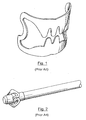
- the system is shown in figures 1 and 2 and comprises an endoscopic device with an endoscope cap at its distal end and a clip removably arranged on the outer surface of the endoscopic cap.
- the surgical clip is formed by a pair of elastically connected semicircular grasping surfaces, or jaws, having toothed portions facing to each other.
- the clip When the clip is mounted on the endoscope cap, the clip is in its open, or tissue receiving, position with the toothed portions spaced apart therebetween and elastically forcing on the outer surface of the cap. Once the clip is released under the action of a deployment device, it closes to its tissue grasping position, in which the toothed portions of the jaws are close to each other to grasp the tissue and assist in retaining it between the two yaws.
- the two jaws are elastically connected by respective joints that bias the jaws toward each other providing the compression force required to enable the jaws to compress and retain tissue therebetween.
- the surgical clip is deployed off of the endoscope cap after it has been positioned adjacent to the wound site.
- the deployment device associated with the surgical clip may be of the type including a cable looped around a portion of the clip and actuated by the operator, for pulling forward the clip and deploying it off of the endoscope cap, or of the type including a tubular member movably mounted on the endoscope and actuated by the operator to push the clip from the underside and deploy it off of the endoscope cap.
- Wireless endoscopic procedures for painless diagnostic exploration of the gastrointestinal tract are also known.
- the procedure requires a patient to ingest a vitamin-pill size capsule which is carried by peristalsis through the digestive tract.
- the capsule takes images which are transmitted to an array of antennas placed externally at the patient's abdomen and recorded into a portable storage unit attached to a belt around the patient's waist.
- the acquisition of images takes eight hours and during this time patients are free to conduct their daily activities.
- the device is expelled naturally after approximately 24 hours, if no complications arise.
- the patient returns to the physician's office to deliver the capsule and the associated equipment to download the images into the physician's workstation for review and analysis.
- An endoscopic capsule for wireless endoscopic procedure comprises a capsule body, a viewing window on the capsule body and a light source such as a LED to illuminate the inner portions of the digestive system, an image sensor to take images and a focusing system, a transmitter, a power source and a data processing unit which generates tracking and video data from the single datastream.
- a commercial capsule according to this patent is the PillCam® capsule marketed in the United States by InScope, a business division of Johnson & Johnson subsidiary Ethicon Endo-Surgery, for the visualisation of the mucosa of small bowel, colon and esophagus.
- a similar device is produced by Olympus Corporation and marketed under the name EndoCapsule for the small bowel.
- endoscopic capsules of the above mentioned type move passively through the gastrointestinal tract and thus their movements cannot be controlled.
- Self propelled and remotely controlled endoscopic capsules have also been disclosed.
- WO2005122866 discloses the application of magnetic forces to permanent magnets in the capsule to move, rotate and stop the capsule in the digestive tract.
- US2006030754 disclose an active control system for a endoscopic capsule comprising a motor consisting of an electromagnetic stator unit and a permanently magnetized rotor unit, in particular in the form of blades attached to a rotatable axis.
- the internal power source may receive power from external ultrasonic power sources, electromagnetic wave sources or magnetic sources.
- EP1715789 discloses an active locomotion system for an endoscopic capsule obtained by means of a set of retractable legs in superelastic SMA housed in axial grooves of the capsule body.
- Each leg has an active degree of freedom (DOF), to allow rotation of the whole leg around a pivot point to open and close each leg radially, and a passive DOF to bend the leg around an intermediate portion for adapting it to the deformability of the tissue of the gastrointestinal tract.
- DOF active degree of freedom
- the endoscopic capsules of the above mentioned type have no therapeutic treatment ability due to the limited space in the capsule.
- the capsule should be equipped with additional mechanical and/or electronical components, which would enlarge the capsule to a unswallowable size.
- the energy supply for such a therapeutic mechanism would have to be ensured, which would require more space to be provided for energy storage means.
- the general object of the present invention is to provide wireless capsular therapeutic treatment ability with lower energy consuming treatment mechanisms.
- Another object of the present invention is to provide a wireless capsule capable of moving in the gastrointestinal tract for delivering a surgigal clip to a Gl site without the need of tubular endoscopic devices to be introduced in the patient body through a body orifice.
- a further object of the present invention is to provide a wireless capsule of the above mentioned type with a surgical clip mounted thereon in such a way to be easily dispensed to a surgical site in the Gl tract ensuring an effective tissue compression and tissue capture for the treatment of Gl diseases.
- a particular object of the present invention is to provide a wireless capsule of the above mentioned type in which both the clip compression strength and the clip releasing action are achieved with a minimum energy demand.
- the wireless capsule of the invention comprises a capsule body with a front portion and a surgical clip releasably mounted on the front portion of said capsule body.
- the capsule body is equipped with wireless locomotion and steering means and image sensing means for taking images of the Gl tract and assisting in leading the capsule up to the target site.
- a transceiver unit for transmitting the detected images to a data processing unit external to the patient and for receiving control signals from an operator is also provided.
- Clip retaining and releasing means are provided for retaining the clip on the front portion of the capsule body when the capsule is moved through the Gl tract, the clip retaining and releasing means being wirelessly actuable for releasing the clip when the capsule is in close proximity of the target surgical site and is directed towards it.
- the wireless capsule is provided with clip retaining and releasing means comprising retractable stoppers, in particular in the form of hooks or pins, projecting from the outer surface of the front portion of the capsule body before the clip.
- the clip forcibly abuts against the stoppers and a motorized release mechanism is provided inside the capsule body for retracting the stoppers, whereby the clip is released to grasp the tissue at the target site axially facing the capsule.
- the retaining and releasing means comprise collapsible stoppers, in particular in the form of fluid inflatable bodies or shape memory alloy (SMA) bodies, projecting from the outer surface of the front portion of the capsule body before the clip.
- the clip forcibly abuts against the stoppers and means are provided inside the capsule body for collapsing the stoppers, in such a way that the clip is released to grasp the tissue at the target site axially facing the capsule.
- the clip retaining and releasing means comprise pushing means for axially sliding the clip on the outer surface of the front portion of the capsule body until the front edge of the capsule is reached to release the clip.
- the pushing means may be in the form of a motorized sleeve or ring coaxially movable at the rear side of the clip on the outer surface of the capsule body.
- capsule means a substantially pill-size elongate cylindrical container with rounded off edges and suitable to be swallowed whole.
- the capsule for delivering a surgical clip at a target area of the gastrointestinal tract comprises a capsule body 1 of a substantially cylindrical shape closed at one end with a cap 2.
- the capsule has a front portion 3 extending from the other end of the capsule body 1 for supporting a surgical clip 4.
- the surgical clip 4 is of the known type as disclosed in US 6428548 , such as for example the clip shown in figure 1 , and is formed by a pair of semicircular tissue grasping surfaces or jaws 4a,b, each having a toothed portion 4c, the jaws being connected to each other at their respective ends by elastic joints 4d.
- the capsule is equipped with a release device, generally indicated at 5 in figure 4 , performing the functions to retain the clip, when the capsule is inoperative and when it is being moved through the gastrointestinal tract and directed toward the target area, and to allow launching the clip once the capsule reaches the target site and its front portion is oriented towards the site.
- a release device generally indicated at 5 in figure 4 , performing the functions to retain the clip, when the capsule is inoperative and when it is being moved through the gastrointestinal tract and directed toward the target area, and to allow launching the clip once the capsule reaches the target site and its front portion is oriented towards the site.
- the release device 5 comprises a first lever 6 housed in a seat 7 in the capsule body 1 and with one end pivotally connected to the seat 7 through a first pin 8 orthogonal to the longitudinal axis A of the capsule.
- the first lever 6 extends in a substantially axial direction and is pivotally connected to one end of a second lever 9 through a second pin 10, parallel to first pin 8.
- the other end of second lever 9 is pivotally connected to a third pin 11 parallel to pins 8 and 10 and mounted for slidably translating along an axial slot 12 formed in the seat 7 of the capsule body 1.
- the third pin 11 has enlarged guide ends 11 a for sliding on the side edges of the slot 12 and preventing the pin to escape from slot 12.
- a pair of arms 13 and 14 are pivotaly connected to third pin 11 at one of their ends. Arms 13 and 14 lie on planes parallel to the lying planes of first and second levers 6 and 9 and extend in directions symmetrically inclined with respect to the longitudinal axis A of the capsule. The other ends of arm 13 and 14 are pivotally connected to respective hook means 15 and 16 each comprising a retractable hook portion 15a and 16a projecting from diametrically opposed slots 17 and 18 formed on front portion 3 of capsule body 1.
- Hook means 15 and 16 are formed by two coplanar plates 15b and 16b pivotally connected to seat 7 of the capsule body 1 through respective fourth pins 19 and 20, parallel to third pin 11, and having respective fifth pins 21 and 22 fixedly extending from plates 15b and 16b to pivotally connect these plates to arms 13 and 14 respectively.
- Fifth pins 21 and 22 are placed at a substantially diametrically opposed sides of plates 15b and 16b relative to fourth pins 19 and 20.
- a motor 23 is placed in a seat 24 formed in the capsule body 1 parallel to the longitudinal axis of the capsule.
- the shaft of the motor 23 is supported for rotation in a bearing 25 at one end of seat 24 and a cam 26 is mounted on shaft 25 in an axial position such that the cam is in close proximity to the connection between first and second levers 6 and 9, in particular in correspondence to second pin 10.
- the profile of cam 26 is such that its minimum radius is not greater than the distance of the axis of the motor shaft from the edge of levers 6,9, while its maximum diameter is greater than this distance.
- the clip 4 forces against the hook portions 15a and 16a of the hook means 15 and 16 projecting from the surface of the front portion 3 of capsule body 1 due to the elastic force stored on the clip to keep it in an enlarged condition.
- the force exerted on the hook portions 15a, 16a causes a compression force on third pin 11, directed along the longitudinal axis A, which, when first and second levers 6,9 are axially aligned, is discharged on first pin 8 thus keeping the mechanism in a stable equilibrium condition and allowing the hook portions 15a, 16a to retain the clip on the front portion 3 of body capsule 1.
- cam 26 Upon actuation of the motor 23, a rotation of the motor shaft causes interference between cam 26 and levers 6,9.
- the pushing action exerted by the cam 26 unbalances the equilibrium condition of the mechanism, which immediately passes to the condition shown in figure 5 .
- cam 26 urges the edges of levers 6,9 with its larger profile section thus displacing sidewards second pin 10 and causing levers 6,9 to rotate on their respective pins 8 and 11.
- the misalignment of first and second levers 6 and 9 causes the sliding of third pin 11 along axial slot 12, this resulting in opposite angular displacements of plates 15b, 16b and the consequent retraction of the hook portions 15a, 16a.
- the clip being no longer retained by the hook portions, is fired towards the target site by the action of the elastic force stored therewith.
- a flexible rod 37 is provided between the cam 26 and the lever 6.
- the rod 37 extends from the seat 7 and is flexibly pushed against lever 6, 9 by the rotating cam.
- the capsule is equipped with an on-board power source 27, such as a battery or a wireless energy supply system, to provide energy to the motor and to an on-board electronic control unit 39 and a video and imaging unit 38.
- the on-board electronic control unit is designed to transmit/receive commands or requests, transmit videos and/or images, acquiring data from sensors possibly equipped with the capsule.
- the control unit is equipped with microcontroller, wireless transmitter / receiver and high current drivers for actuator.
- a controller is also provided for the video and imaging unit.
- the battery can be of the Lithium Polymer rechargeable type and a wireless battery charger unit is provided.
- the actuator can be a miniaturized DC brushless motor, controlled by a full bridge CMOS driver.
- the driver should be properly connected to the microcontroller, which is also in charge to wirelessly communicate with an external unit thorugh a dedicated wireless transceiver.
- a CMOS or CCD imaging sensor is used to acquire real time images, together with a proper illumination module.
- the image data stream is sent to the external unit by the telemetric link.
- External facilities include a wireless dongle unit and a wireless video receiver unit and allow the collected data to be sent to a personal computer or a laptop for further processing.
- a wireless transceiver can be used for a bidirectional communication with the microcontroller inside the capsule and to receive the real time video streaming.
- the transceiver would be connected to a personal computer by a dedicate port, e.g. USB port.
- An user interface is implemented on the PC in order to properly display the image data and information related to the capsule operative status (e.g. battery level, telemetry signal strength, etc.).
- the user interface would also allow the user to fire the clip by pushing a dedicate button located on visual display.
- Possible strategies for capsule locomotion, orientation and steering range from internal to external solutions may be implemented by placing a further actuator on board the capsule, as in PCT/IT2007/000259 .
- external strategies may prove to be more efficient.
- An example is external magnetic locomotion, where several small permanent magnets are placed on board the capsule and an external magnet, either permanent or composed by coils, is used to steer the capsule under the user control.
- a solution of this type is disclosed for example in WO05122866 , wherein the capsule is equipped with permanent magnets or elecromagnets and magnetic forces are applied to them by means of an external permanent magnet which is moved by the physician.
- four permanent magnets 28 are arranged in respective axial seats 29 formed on the outer surface of the capsule body 1.
- the Gl cavity wherein the capsule has to be moved is blown with air or other suitable gas or gas mixture to stretch the cavity walls.
- FIG. 8 shows an alternative embodiment of clip releasing device for the wireless surgical clip delivering capsule according to the invention.
- the clip mounted on the front portion 3 of the capsule body 1 is passively released and the retaining action on the clip is provided by a pair of opposed stopper pins 30 diametrically projecting from the outer surface of the front portion 3 and operatively retractable therein as a result of an axial forward movement of a motorized slide 31 to which the pins 30 are connected.
- slide 31 is formed with two forwardly inclined slots 32 converging on the longitudinal axis A of the capsule, in which respective pegs 33 radially extending from stopper pins 30 are slidingly engaged.
- a motor 34 is axially housed in the capsule body 3 to rotate an axial screw 35 engaged with a nut screw (not shown) integral to slide 31. In this way a rotation of the screw 35 causes an axial movement of slide 31 and the retraction of pins 30.
- a joint 36 such as a Oldahm joint, is provided between axial screw 35 and the motor shaft to reduce any placement error.
- the front portion 3 of capsule body 1 has a frusto-conical shape to make the clip release easier.
- Figures 9a and 9b show a first variation of the clip releasing device of figure 8 , in which the stopper pins 30 are replaced by small bodies such as spheres 40 projecting from the outer surface of front portion 3 of body capsule 1 to retain the clip 4.
- the spheres are made of SMA (Shape Memory Alloy) material and, when they are put under proper voltage, they collapse suddenly as shown in figure 9b causing the release of the clip 4.
- SMA Shape Memory Alloy
- Figures 10a and 10b show a second variation of the clip releasing device of figure 8 , in which the stopper pins 30 are replaced by elastic bubbles 50 projecting from the front portion 3 of capsule body 1 to retain the clip 4 when they are full of a fluid.
- the bubbles 50 are hydraulically connected via tubes 51 to a chamber 52, whose volume can be varied by the movement of a piston 53 moved by an actuator 54.
- An increase of the volume of chamber 52 correspond to a suction action on the bubbles which collapse due to their emptying out as shown in figure 10b causing the release of the clip 4.
- FIGs 11 a and 11 b show a further embodiment of the clip releasing device, in which the clip is actively released from the capsule.
- the front portion 3 of capsule body 1 on which the clip 4 is mounted has an outer surface 60 that can be raised ouwardly upon the action of a pushing member 61, which is retracted when the capsule is inoperative and projects outwards when the clip has to be released.
- the pushing member 61 is placed behind the clip 4, so that, when the outer surface 60 is raised, the supporting plane of the clip is inclined to cause it to be quickly released, as shown in figure 11 b.
- the pushing member 61 may be actuated by a mechanism such as that shown in figures 3 to 8 .
- FIG. 12a and 12b A variation of the above described active clip releasing device is shown in figures 12a and 12b , in which the clip 4 is pushed from a rest position shown in figure 12a to slide on the outer surface of front portion 3 of capsule body 1 until it reaches the front edge 3a of capsule body 1 and is released.
- a pushing member 70 for example in the form of a coaxial sleeve or ring, can be provided and actuated by an axially moving mechanism, inside the capsule, radially connected to the pushing member.
- the capsule at its front end, with tissue manipulation means for holding or withdrawing the tissue to be grasped by the clip before the clip is fired and in particular for moving the tissue close to the front end of the capsule before the clip is released.
- tissue manipulation means for holding or withdrawing the tissue to be grasped by the clip before the clip is fired and in particular for moving the tissue close to the front end of the capsule before the clip is released.
- sucker or an adhesive plate or hook/screw means for securing the capsule to the target site for a short time before the clip is released.
- Figures 13a and 13b show an embodiment of the invention in which the capsule is equipped with an hook 80 housed in a seat 81 formed sideways at the front end 3 and parallel to the longitudinal axis A.
- the hook 80 is fired against the tissue T by an actuator, not shown, to get its tip stuck in the tissue.
- the capsule or the hook slightly goes back to draw out a tissue portion while the clip is released as shown in figure 13b .
- the clip grasps the tissue, the hook is released from the capsule.
- the use of a hook as aid for the grasping action may also assist in stabilizing the position of the capsule relative to the tissue when the clip is fired.
- the capsule can be of the swallowable type and can be advantageously coated with a biocompatible and biodegradable layer that makes the swallowing action easier and safer.
- the coating is destroyed by the acidity of the environment thus allowing it to become operative.
- the wireless capsule for delivering a surgical clip allows a surgical clip, such that disclosed in US6428548 , to be released by a wireless device instead of a flexible and tubular endoscope.
- the clip may be dispensed by a swallowable small pill dramatically reducing the pain and disconfort for the patient and increasing the number of potential candidates for this procedure.
- it will be possible to release the clip in areas of the gastrointestinal tract, such as the small bowel, that are unreachable and/or out of the operative field for most of the prior art endoscopic devices. This may open the way to innovative therapeutical procedures that were impossible before.
- a kind of novel surgical procedure that can take tremendous advantage by this invention is the Natural Orifice Transluminal Endoscopic Surgery (NOTES).
- NOTES Natural Orifice Transluminal Endoscopic Surgery
- This is an experimental surgery technique wherein "scarless" abdominal operations can be performed with an endoscope passed through a natural body lumen (mouth, uretra, anus, etc.) then through an internal incision in the stomach, vagina, bladder or colon, thus avoiding any external incision or scars.
- Using a wireless device instead of a flexible endoscope may dramatically improve the efficiency and the results of this new technique.
- Another example of application is in the Bleeding Peptic Ulcer Disease, which can be a critical event owing to the fact that there is an internal haemorrhage associated with the ulcer.
- Another field of application of the capsule according to the present invention may be when a support for operating a surgical instrument or device has to be created in a body cavity or organ, in particular of the Gl tract.
- the capsule of the present invention may be used to secure the clip serving as a support in the selected position.
- the capsule according to the invention can be modified and varied in several ways, all of which are within the scope of the invention. All the details may further be replaced with other technically equivalent elements. In practice, the materials used, so long as they are compatible with the specific use, as well as the dimensions, may be any according to the requirements and the state of the art.
Abstract
Description
- The present invention relates generally to a wireless medical device for compressing body tissue to prevent haemorrhaging, treating of lesion, and marking of suspected tissue area at a surgical site within the gastrointestinal (Gl) tract. More specifically the invention relates to a wireless capsular device for delivering a surgical clip to a selected site of the gastrointestinal tract.
-
US 6428548 discloses a surgical clip and a system for delivering the clip in a controlled way to a surgical site. This system is intended for use in a variety of medical procedures, including closing an organ perforation from inside a lumen by approximating and compressing the wound edges of the perforated tissue. The system is shown infigures 1 and 2 and comprises an endoscopic device with an endoscope cap at its distal end and a clip removably arranged on the outer surface of the endoscopic cap. The surgical clip is formed by a pair of elastically connected semicircular grasping surfaces, or jaws, having toothed portions facing to each other. When the clip is mounted on the endoscope cap, the clip is in its open, or tissue receiving, position with the toothed portions spaced apart therebetween and elastically forcing on the outer surface of the cap. Once the clip is released under the action of a deployment device, it closes to its tissue grasping position, in which the toothed portions of the jaws are close to each other to grasp the tissue and assist in retaining it between the two yaws. - The two jaws are elastically connected by respective joints that bias the jaws toward each other providing the compression force required to enable the jaws to compress and retain tissue therebetween.
- In the use, the surgical clip is deployed off of the endoscope cap after it has been positioned adjacent to the wound site. The deployment device associated with the surgical clip may be of the type including a cable looped around a portion of the clip and actuated by the operator, for pulling forward the clip and deploying it off of the endoscope cap, or of the type including a tubular member movably mounted on the endoscope and actuated by the operator to push the clip from the underside and deploy it off of the endoscope cap.
- As any endoscopic procedure, the use of the system for delivering a surgical clip in a controlled way to a surgical site according to
US 6428548 entails that a clip dispenser, either a flexible endoscope or another tubular device, be introduced in the patient body through a body orifice and this usually causes serious discomfort and pain to the patient, which is often significantly discouraged to undergo this type of treatment procedures. Furthermore, when using a conventional endoscope, although of the flexible type, it may be very difficult and often impossible to dispense the surgical clip to some segments of the gastrointestinal tract, for example the small bowel. - Wireless endoscopic procedures for painless diagnostic exploration of the gastrointestinal tract are also known. The procedure requires a patient to ingest a vitamin-pill size capsule which is carried by peristalsis through the digestive tract. During the transit the capsule takes images which are transmitted to an array of antennas placed externally at the patient's abdomen and recorded into a portable storage unit attached to a belt around the patient's waist. The acquisition of images takes eight hours and during this time patients are free to conduct their daily activities. The device is expelled naturally after approximately 24 hours, if no complications arise. Then the patient returns to the physician's office to deliver the capsule and the associated equipment to download the images into the physician's workstation for review and analysis.
- An endoscopic capsule for wireless endoscopic procedure, as disclosed for instance in
US 5604531 , comprises a capsule body, a viewing window on the capsule body and a light source such as a LED to illuminate the inner portions of the digestive system, an image sensor to take images and a focusing system, a transmitter, a power source and a data processing unit which generates tracking and video data from the single datastream. A commercial capsule according to this patent is the PillCam® capsule marketed in the United States by InScope, a business division of Johnson & Johnson subsidiary Ethicon Endo-Surgery, for the visualisation of the mucosa of small bowel, colon and esophagus. A similar device is produced by Olympus Corporation and marketed under the name EndoCapsule for the small bowel. - The endoscopic capsules of the above mentioned type move passively through the gastrointestinal tract and thus their movements cannot be controlled. Self propelled and remotely controlled endoscopic capsules have also been disclosed. For example
WO2005122866 discloses the application of magnetic forces to permanent magnets in the capsule to move, rotate and stop the capsule in the digestive tract.US2006030754 disclose an active control system for a endoscopic capsule comprising a motor consisting of an electromagnetic stator unit and a permanently magnetized rotor unit, in particular in the form of blades attached to a rotatable axis. The internal power source may receive power from external ultrasonic power sources, electromagnetic wave sources or magnetic sources.EP1715789 discloses an active locomotion system for an endoscopic capsule obtained by means of a set of retractable legs in superelastic SMA housed in axial grooves of the capsule body. Each leg has an active degree of freedom (DOF), to allow rotation of the whole leg around a pivot point to open and close each leg radially, and a passive DOF to bend the leg around an intermediate portion for adapting it to the deformability of the tissue of the gastrointestinal tract. - The endoscopic capsules of the above mentioned type have no therapeutic treatment ability due to the limited space in the capsule. To enable a therapeutic treatment ability the capsule should be equipped with additional mechanical and/or electronical components, which would enlarge the capsule to a unswallowable size. Furthermore, even if the capsule would be maintained to a swallowable size, the energy supply for such a therapeutic mechanism would have to be ensured, which would require more space to be provided for energy storage means.
- The general object of the present invention is to provide wireless capsular therapeutic treatment ability with lower energy consuming treatment mechanisms.
- Another object of the present invention is to provide a wireless capsule capable of moving in the gastrointestinal tract for delivering a surgigal clip to a Gl site without the need of tubular endoscopic devices to be introduced in the patient body through a body orifice.
- A further object of the present invention is to provide a wireless capsule of the above mentioned type with a surgical clip mounted thereon in such a way to be easily dispensed to a surgical site in the Gl tract ensuring an effective tissue compression and tissue capture for the treatment of Gl diseases.
- A particular object of the present invention is to provide a wireless capsule of the above mentioned type in which both the clip compression strength and the clip releasing action are achieved with a minimum energy demand.
- These object are achieved with the wireless capsule for delivering a surgical clip to a surgical site of the Gl tract according to the present invention whose essential features are set forth in claim 1. Further important features are specified in the dependent claims.
- According to one aspect of the invention the wireless capsule of the invention comprises a capsule body with a front portion and a surgical clip releasably mounted on the front portion of said capsule body. The capsule body is equipped with wireless locomotion and steering means and image sensing means for taking images of the Gl tract and assisting in leading the capsule up to the target site. A transceiver unit for transmitting the detected images to a data processing unit external to the patient and for receiving control signals from an operator is also provided. Clip retaining and releasing means are provided for retaining the clip on the front portion of the capsule body when the capsule is moved through the Gl tract, the clip retaining and releasing means being wirelessly actuable for releasing the clip when the capsule is in close proximity of the target surgical site and is directed towards it.
- In this way the elastic energy stored in the clip once it is mounted on the capsule is exploited both for providing all the compression strength necessary for tissue grasping, without the need of an additional mechanism for generating the compression strength, and for releasing the clip, thus significantly simplifying the releasing mechanism.
- According to another aspect of the invention, the wireless capsule is provided with clip retaining and releasing means comprising retractable stoppers, in particular in the form of hooks or pins, projecting from the outer surface of the front portion of the capsule body before the clip. The clip forcibly abuts against the stoppers and a motorized release mechanism is provided inside the capsule body for retracting the stoppers, whereby the clip is released to grasp the tissue at the target site axially facing the capsule.
- In a different embodiment of the invention the retaining and releasing means comprise collapsible stoppers, in particular in the form of fluid inflatable bodies or shape memory alloy (SMA) bodies, projecting from the outer surface of the front portion of the capsule body before the clip. The clip forcibly abuts against the stoppers and means are provided inside the capsule body for collapsing the stoppers, in such a way that the clip is released to grasp the tissue at the target site axially facing the capsule.
- According to a further aspect of the invention the clip retaining and releasing means comprise pushing means for axially sliding the clip on the outer surface of the front portion of the capsule body until the front edge of the capsule is reached to release the clip. Advantageously, the pushing means may be in the form of a motorized sleeve or ring coaxially movable at the rear side of the clip on the outer surface of the capsule body.
- The features and the advantages of the wireless capsule for delivering a surgical clip to a surgical site according to the present invention will be apparent from the following description of exemplifying, non-limiting embodiments thereof made with reference to the accompanying drawings, in which:
-
Figures 1 and 2 are perspective views of a surgical clip and an endoscopic clip dispenser according to the prior art; -
Figure 3 is a side perspective view of the capsule according to the invention; -
Figure 4 is a perspective longitudinal sectional view of the capsule offigure 3 showing the releasing device in its clip retaining position; -
Figure 5 is a perspective longitudinal sectional view of the capsule showing the releasing device in its clip launching position; -
Figure 6 is another perspective longitudinal sectional view of the capsule taken alog lines VI-VI offigure 4 with parts removed for clarity; -
Figure 7 is a perspective cross-sectional view of the capsule taken along lines VII-VII offigure 4 ; -
Figure 8 is a perspective longitudinal sectional view of the capsule of the invention showing a first alternative embodiment of the releasing device; -
Figures 9a and 9b schematically show a second alternative embodiment of the releasing device in a retaining and launching position respectively; -
Figures 10a and 10b schematically show a third alternative embodiment of the releasing device in a retaining and launching position respectively; -
Figures 11 a and 11 b schematically show a fourth alternative embodiment of the releasing device in a retaining and launching position respectively; -
Figures 12a and 12b schematically show a fifth alternative embodiment of the releasing device in a retaining and launching position respectively; -
Figures 13a and 13b schematically show an embodiment of the invention in which means for hooking the tissue at the target area are provided. - As used herein, the word "capsule" means a substantially pill-size elongate cylindrical container with rounded off edges and suitable to be swallowed whole.
- With reference to
figure 3 the capsule for delivering a surgical clip at a target area of the gastrointestinal tract according to the invention comprises a capsule body 1 of a substantially cylindrical shape closed at one end with acap 2. The capsule has afront portion 3 extending from the other end of the capsule body 1 for supporting asurgical clip 4. In particular, thesurgical clip 4 is of the known type as disclosed inUS 6428548 , such as for example the clip shown infigure 1 , and is formed by a pair of semicircular tissue grasping surfaces or jaws 4a,b, each having a toothed portion 4c, the jaws being connected to each other at their respective ends byelastic joints 4d. - The capsule is equipped with a release device, generally indicated at 5 in
figure 4 , performing the functions to retain the clip, when the capsule is inoperative and when it is being moved through the gastrointestinal tract and directed toward the target area, and to allow launching the clip once the capsule reaches the target site and its front portion is oriented towards the site. - According to the embodiment shown in
figures 3 to 7 , the release device 5 comprises afirst lever 6 housed in a seat 7 in the capsule body 1 and with one end pivotally connected to the seat 7 through afirst pin 8 orthogonal to the longitudinal axis A of the capsule. Thefirst lever 6 extends in a substantially axial direction and is pivotally connected to one end of asecond lever 9 through asecond pin 10, parallel tofirst pin 8. The other end ofsecond lever 9 is pivotally connected to athird pin 11 parallel topins third pin 11 has enlarged guide ends 11 a for sliding on the side edges of the slot 12 and preventing the pin to escape from slot 12. - A pair of
arms third pin 11 at one of their ends.Arms second levers arm retractable hook portion opposed slots 17 and 18 formed onfront portion 3 of capsule body 1. Hook means 15 and 16 are formed by two coplanar plates 15b and 16b pivotally connected to seat 7 of the capsule body 1 through respectivefourth pins third pin 11, and having respectivefifth pins arms Fifth pins fourth pins - A
motor 23 is placed in aseat 24 formed in the capsule body 1 parallel to the longitudinal axis of the capsule. The shaft of themotor 23 is supported for rotation in abearing 25 at one end ofseat 24 and acam 26 is mounted onshaft 25 in an axial position such that the cam is in close proximity to the connection between first andsecond levers second pin 10. The profile ofcam 26 is such that its minimum radius is not greater than the distance of the axis of the motor shaft from the edge oflevers - When the
clip 4 is mounted on thefront portion 3 of capsule body 1, as shown infigure 3 , theclip 4 forces against thehook portions front portion 3 of capsule body 1 due to the elastic force stored on the clip to keep it in an enlarged condition. The force exerted on thehook portions third pin 11, directed along the longitudinal axis A, which, when first andsecond levers first pin 8 thus keeping the mechanism in a stable equilibrium condition and allowing thehook portions front portion 3 of body capsule 1. - Upon actuation of the
motor 23, a rotation of the motor shaft causes interference betweencam 26 andlevers cam 26 unbalances the equilibrium condition of the mechanism, which immediately passes to the condition shown infigure 5 . In fact,cam 26 urges the edges oflevers second pin 10 and causinglevers respective pins second levers third pin 11 along axial slot 12, this resulting in opposite angular displacements of plates 15b, 16b and the consequent retraction of thehook portions - Advantageously, to better distribute the force exerted by the
cam 26 onlevers cam 26 and thelever 6. The rod 37 extends from the seat 7 and is flexibly pushed againstlever - The capsule is equipped with an on-
board power source 27, such as a battery or a wireless energy supply system, to provide energy to the motor and to an on-boardelectronic control unit 39 and a video andimaging unit 38. In particular, the on-board electronic control unit is designed to transmit/receive commands or requests, transmit videos and/or images, acquiring data from sensors possibly equipped with the capsule. The control unit is equipped with microcontroller, wireless transmitter / receiver and high current drivers for actuator. A controller is also provided for the video and imaging unit. The battery can be of the Lithium Polymer rechargeable type and a wireless battery charger unit is provided. - The actuator can be a miniaturized DC brushless motor, controlled by a full bridge CMOS driver. The driver should be properly connected to the microcontroller, which is also in charge to wirelessly communicate with an external unit thorugh a dedicated wireless transceiver. A CMOS or CCD imaging sensor is used to acquire real time images, together with a proper illumination module. The image data stream is sent to the external unit by the telemetric link.
- External facilities include a wireless dongle unit and a wireless video receiver unit and allow the collected data to be sent to a personal computer or a laptop for further processing. In particular, a wireless transceiver can be used for a bidirectional communication with the microcontroller inside the capsule and to receive the real time video streaming. The transceiver would be connected to a personal computer by a dedicate port, e.g. USB port. An user interface is implemented on the PC in order to properly display the image data and information related to the capsule operative status (e.g. battery level, telemetry signal strength, etc.). The user interface would also allow the user to fire the clip by pushing a dedicate button located on visual display.
- Possible strategies for capsule locomotion, orientation and steering range from internal to external solutions. In particular, internal strategies may be implemented by placing a further actuator on board the capsule, as in
PCT/IT2007/000259 - A solution of this type is disclosed for example in
WO05122866 permanent magnets 28 are arranged in respectiveaxial seats 29 formed on the outer surface of the capsule body 1. For a proper operation of the capsule the Gl cavity wherein the capsule has to be moved is blown with air or other suitable gas or gas mixture to stretch the cavity walls. -
Figure 8 shows an alternative embodiment of clip releasing device for the wireless surgical clip delivering capsule according to the invention. In this embodiment the clip mounted on thefront portion 3 of the capsule body 1 is passively released and the retaining action on the clip is provided by a pair of opposed stopper pins 30 diametrically projecting from the outer surface of thefront portion 3 and operatively retractable therein as a result of an axial forward movement of amotorized slide 31 to which thepins 30 are connected. In particular, slide 31 is formed with two forwardlyinclined slots 32 converging on the longitudinal axis A of the capsule, in whichrespective pegs 33 radially extending from stopper pins 30 are slidingly engaged. Amotor 34 is axially housed in thecapsule body 3 to rotate anaxial screw 35 engaged with a nut screw (not shown) integral to slide 31. In this way a rotation of thescrew 35 causes an axial movement ofslide 31 and the retraction ofpins 30. Preferably, a joint 36, such as a Oldahm joint, is provided betweenaxial screw 35 and the motor shaft to reduce any placement error. - Preferably, the
front portion 3 of capsule body 1 has a frusto-conical shape to make the clip release easier. -
Figures 9a and 9b show a first variation of the clip releasing device offigure 8 , in which the stopper pins 30 are replaced by small bodies such asspheres 40 projecting from the outer surface offront portion 3 of body capsule 1 to retain theclip 4. The spheres are made of SMA (Shape Memory Alloy) material and, when they are put under proper voltage, they collapse suddenly as shown infigure 9b causing the release of theclip 4. -
Figures 10a and 10b show a second variation of the clip releasing device offigure 8 , in which the stopper pins 30 are replaced byelastic bubbles 50 projecting from thefront portion 3 of capsule body 1 to retain theclip 4 when they are full of a fluid. Thebubbles 50 are hydraulically connected via tubes 51 to achamber 52, whose volume can be varied by the movement of apiston 53 moved by anactuator 54. An increase of the volume ofchamber 52 correspond to a suction action on the bubbles which collapse due to their emptying out as shown infigure 10b causing the release of theclip 4. - The advantages of embiodiments shown in
figures 9a,b and 10a,b relative to embodiments shown infigures 3 to 8 , may consist in that less mechanical components are required. -
Figures 11 a and 11 b show a further embodiment of the clip releasing device, in which the clip is actively released from the capsule. In this case thefront portion 3 of capsule body 1 on which theclip 4 is mounted has anouter surface 60 that can be raised ouwardly upon the action of a pushingmember 61, which is retracted when the capsule is inoperative and projects outwards when the clip has to be released. The pushingmember 61 is placed behind theclip 4, so that, when theouter surface 60 is raised, the supporting plane of the clip is inclined to cause it to be quickly released, as shown infigure 11 b. The pushingmember 61 may be actuated by a mechanism such as that shown infigures 3 to 8 . - A variation of the above described active clip releasing device is shown in
figures 12a and 12b , in which theclip 4 is pushed from a rest position shown infigure 12a to slide on the outer surface offront portion 3 of capsule body 1 until it reaches the front edge 3a of capsule body 1 and is released. To push theclip 4 at the back a pushingmember 70, for example in the form of a coaxial sleeve or ring, can be provided and actuated by an axially moving mechanism, inside the capsule, radially connected to the pushing member. - In order to make easier the grasping action of the clip it may be advantageous to provide the capsule, at its front end, with tissue manipulation means for holding or withdrawing the tissue to be grasped by the clip before the clip is fired and in particular for moving the tissue close to the front end of the capsule before the clip is released. To this end it may be useful to equip the front end of the capsule with a sucker or an adhesive plate or hook/screw means for securing the capsule to the target site for a short time before the clip is released.
-
Figures 13a and 13b show an embodiment of the invention in which the capsule is equipped with anhook 80 housed in a seat 81 formed sideways at thefront end 3 and parallel to the longitudinal axis A. Once the capsule reaches the target site thehook 80 is fired against the tissue T by an actuator, not shown, to get its tip stuck in the tissue. Then the capsule or the hook slightly goes back to draw out a tissue portion while the clip is released as shown infigure 13b . Once the clip grasps the tissue, the hook is released from the capsule. The use of a hook as aid for the grasping action may also assist in stabilizing the position of the capsule relative to the tissue when the clip is fired. - The capsule can be of the swallowable type and can be advantageously coated with a biocompatible and biodegradable layer that makes the swallowing action easier and safer. When the capsule reaches the stomach, the coating is destroyed by the acidity of the environment thus allowing it to become operative.
- The wireless capsule for delivering a surgical clip according to the present invention allows a surgical clip, such that disclosed in
US6428548 , to be released by a wireless device instead of a flexible and tubular endoscope. The clip may be dispensed by a swallowable small pill dramatically reducing the pain and disconfort for the patient and increasing the number of potential candidates for this procedure. Furthermore, according to the present invention it will be possible to release the clip in areas of the gastrointestinal tract, such as the small bowel, that are unreachable and/or out of the operative field for most of the prior art endoscopic devices. This may open the way to innovative therapeutical procedures that were impossible before. - A kind of novel surgical procedure that can take tremendous advantage by this invention is the Natural Orifice Transluminal Endoscopic Surgery (NOTES). This is an experimental surgery technique wherein "scarless" abdominal operations can be performed with an endoscope passed through a natural body lumen (mouth, uretra, anus, etc.) then through an internal incision in the stomach, vagina, bladder or colon, thus avoiding any external incision or scars. Using a wireless device instead of a flexible endoscope may dramatically improve the efficiency and the results of this new technique. Another example of application is in the Bleeding Peptic Ulcer Disease, which can be a critical event owing to the fact that there is an internal haemorrhage associated with the ulcer. Another field of application of the capsule according to the present invention may be when a support for operating a surgical instrument or device has to be created in a body cavity or organ, in particular of the Gl tract. In this case the capsule of the present invention may be used to secure the clip serving as a support in the selected position.
- The capsule according to the invention can be modified and varied in several ways, all of which are within the scope of the invention. All the details may further be replaced with other technically equivalent elements. In practice, the materials used, so long as they are compatible with the specific use, as well as the dimensions, may be any according to the requirements and the state of the art.
- Wherever the characteristics and techniques described in any claim are followed by a specific reference, these have been included as an example for the sole purpose of making the claim descriptions easier to understand, and therefore they impose no limits on the interpretation of the element they refer to.
Claims (14)
- A wireless capsule for delivering a surgical clip to a target site in the gastrointestinal (Gl) tract of a patient, characterized in that it comprises:- a capsule body (1) with a front portion (3);- a surgical clip (4) releasably mounted on the front portion of said capsule body;- wireless locomotion and steering means (28) mounted on said capsule body;- image sensing means 38 mounted on said capsule body for taking images of the Gl tract and assisting in leading the capsule up to the target site;- a transceiver unit 39 for transmitting the detected images to a data processing unit external to the patient and for receiving control signals from an operator;- clip retaining and releasing means (5) for retaining the clip on said front portion of the capsule body when the capsule is moved through the Gl tract, said clip retaining and releasing means being wirelessly actuable for releasing the clip when the capsule is in close proximity of the target surgical site and is directed towards said site.
- The wireless capsule according to claim 1, wherein said clip retaining and releasing means comprise retractable stoppers (15,16,30,40,50) projecting from the outer surface of the front portion of said capsule body before said clip (4), which forcibly abuts against said stoppers, a motorized release mechanism (5) being provided inside said capsule body for retracting said stoppers, whereby the clip is released to grasp the tissue at the target site axially facing the capsule.
- The wireless capsule according to claim 2, wherein said release mechanism comprise a slider (11,31) and a motor (23,34) for axially moving said slider, the slider being connected to said stoppers (15,16,30) in such a way that its axial sliding causes the stoppers to retract from said outer surface.
- The wireless capsule according to claim 3, wherein said stoppers are in the form of substantially hook-shaped expansions (15a,16a) of at least a pair of plates (15b,16b) pivotally mounted within the front portion of said capsule body, said plates being pivotally connected to respective arms (13,14) at a connection point (21,22) placed at a diametrically opposite side of said expansions, said slider (11) being pivotally connected to said arms (13,14) and to a second lever (9), which, in turn, is pivotally connected to a first lever (6) pivotally connected to a pin (8) fixed to said capsule body and perpendicular to the longitudinal axis (A) of the capsule, said first and second levers (6,9) being axially aligned when said hook-shaped expansions (15a,16a) project from the outer surface of the front portion of the capsule body, a cam (26) driven by said motor being provided at a side of said first and second lever, the cam profile being such that an angular displacement of the cam causes a pushing force to be exerted on said levers in a direction perpendicular to their common pivotal axis, whereby the first and second levers are misaligned and the slider is moved along said longitudinal axis (A), thus retracting said hook-shaped expansions.
- The wireless capsule according to claim 4, wherein the cam (26) is placed close to the common pivotal axis of said first and second lever (6,9).
- The wireless capsule according to claim 3, wherein said stoppers comprise a pair of pins (30) extending at diametrically opposed sides of the front portion of said capsule body, said slider being a plate (31) substantially parallel to said pins and being formed with two symmetrically inclined slots (32) relative to the longitudinal axis (A) of the capsule slidably engaged whith respective feet (33) of said pins, a screw transmission (35) being provided between said motor (34) and said slider (31), whereby an axial angular displacement of the screw causes an axial movement of said slider, thus retracting said pins.
- The wireless capsule according to claim 1, wherein said clip retaining and releasing means comprise collapsible stoppers (40,50) projecting from the outer surface of the front portion of said capsule body before said clip, which forcibly abuts against said stoppers, means being provided inside said capsule body for collapsing the stoppers, in such a way that the clip is released to grasp the tissue at the target site axially facing the capsule.
- The wireless capsule according to claim 7, wherein said collapsible stoppers comprise at least a pair of shape memory alloy (SMA) bodies (40) and said collapsing means are an electric energy supplying circuit connected to said SMA bodies, whereby, when a voltage is applied to said SMA bodies, a sudden size reduction of the SMA bodies occurs and the clip is released.
- The wireless capsule according to claim 7, wherein said collapsible stoppers comprise at least a pair of bubbles (50) full of a fluid and hydraulically connected to a chamber (52), whose volume can be varied by the movement of a piston (53) moved by an actuator (54), whereby an increase of the volume of said chamber corresponds to a suction action on said bubbles which collapse due to their emptying out, thus causing the release of the clip.
- The wireless capsule according to claim 1, wherein said clip retaining and releasing means comprise pushing means (60,70,80)for axially sliding the clip on the outer surface of the front portion of the capsule body until the front edge of said front portion is reached to release said clip.
- The wireless capsule according to claim 10, wherein said pushing means comprise an outwardly expandable surface (60) of said front portion of capsule body and a pushing member (61) acting from inside on side surface for raising outwardly said surface, said pushing member being placed behind the clip, so that, when the outer surface (60) is raised, the supporting plane of the clip is inclined to cause the clip to be quickly released.
- The wireless capsule according to claim 10, wherein said pushing means comprise a sleeve or ring (70) coaxially movable at the rear side of said clip on the outer surface of said front portion of capsule body, said sleeve or ring being moved by motor means placed on-board of said capsule.
- The wireless capsule according to any one of the previous claims, further comprising tissue manipulation means for holding or withdrawing the tissue to be grasped by the clip before the clip is fired.
- The wireless capsule according to claim 13, wherein said tissue manipulation means comprise a sucker or an adhesive plate or hook/screw means (80) for securing the capsule to the target site before the clip is released.
Priority Applications (2)
| Application Number | Priority Date | Filing Date | Title |
|---|---|---|---|
| EP08425604A EP2163206B1 (en) | 2008-09-16 | 2008-09-16 | Surgical clip delivering wireless capsule |
| ES08425604T ES2401166T3 (en) | 2008-09-16 | 2008-09-16 | Wireless capsule that releases a surgical clamp |
Applications Claiming Priority (1)
| Application Number | Priority Date | Filing Date | Title |
|---|---|---|---|
| EP08425604A EP2163206B1 (en) | 2008-09-16 | 2008-09-16 | Surgical clip delivering wireless capsule |
Publications (2)
| Publication Number | Publication Date |
|---|---|
| EP2163206A1 true EP2163206A1 (en) | 2010-03-17 |
| EP2163206B1 EP2163206B1 (en) | 2012-12-12 |
Family
ID=40289140
Family Applications (1)
| Application Number | Title | Priority Date | Filing Date |
|---|---|---|---|
| EP08425604A Not-in-force EP2163206B1 (en) | 2008-09-16 | 2008-09-16 | Surgical clip delivering wireless capsule |
Country Status (2)
| Country | Link |
|---|---|
| EP (1) | EP2163206B1 (en) |
| ES (1) | ES2401166T3 (en) |
Cited By (19)
| Publication number | Priority date | Publication date | Assignee | Title |
|---|---|---|---|---|
| GB2453676B (en) * | 2004-04-19 | 2010-11-10 | Searete Llc | Lumen-traveling biological interface device and method of use |
| CN101897573A (en) * | 2010-09-03 | 2010-12-01 | 吴正奇 | Capsule endoscope pusher |
| US7850676B2 (en) | 2004-04-19 | 2010-12-14 | The Invention Science Fund I, Llc | System with a reservoir for perfusion management |
| US7857767B2 (en) | 2004-04-19 | 2010-12-28 | Invention Science Fund I, Llc | Lumen-traveling device |
| US7879023B2 (en) | 2004-04-19 | 2011-02-01 | The Invention Science Fund I, Llc | System for perfusion management |
| US7998060B2 (en) | 2004-04-19 | 2011-08-16 | The Invention Science Fund I, Llc | Lumen-traveling delivery device |
| US8019413B2 (en) | 2007-03-19 | 2011-09-13 | The Invention Science Fund I, Llc | Lumen-traveling biological interface device and method of use |
| US8092549B2 (en) | 2004-09-24 | 2012-01-10 | The Invention Science Fund I, Llc | Ciliated stent-like-system |
| US8353896B2 (en) | 2004-04-19 | 2013-01-15 | The Invention Science Fund I, Llc | Controllable release nasal system |
| US8361014B2 (en) | 2004-04-19 | 2013-01-29 | The Invention Science Fund I, Llc | Telescoping perfusion management system |
| WO2013027182A1 (en) | 2011-08-23 | 2013-02-28 | Scuola Superiore Di Studi Universitari E Di Perfezionamento Sant'anna | Capsule for local therapy by means of an endoluminal plaster in the gastrointestinal system |
| EP2596756A1 (en) * | 2011-11-22 | 2013-05-29 | Ovesco Endoscopy AG | Implanting apparatus |
| US9011329B2 (en) | 2004-04-19 | 2015-04-21 | Searete Llc | Lumenally-active device |
| US9198563B2 (en) | 2006-04-12 | 2015-12-01 | The Invention Science Fund I, Llc | Temporal control of a lumen traveling device in a body tube tree |
| US9579163B2 (en) | 2011-05-31 | 2017-02-28 | Pietro Valdastri | Robotic platform for mini-invasive surgery |
| US9737364B2 (en) | 2012-05-14 | 2017-08-22 | Vanderbilt University | Local magnetic actuation of surgical devices |
| US9826904B2 (en) | 2012-09-14 | 2017-11-28 | Vanderbilt University | System and method for detecting tissue surface properties |
| US10485409B2 (en) | 2013-01-17 | 2019-11-26 | Vanderbilt University | Real-time pose and magnetic force detection for wireless magnetic capsule |
| US10758111B2 (en) | 2014-09-09 | 2020-09-01 | Vanderbilt University | Hydro-jet endoscopic capsule and methods for gastric cancer screening in low resource settings |
Families Citing this family (1)
| Publication number | Priority date | Publication date | Assignee | Title |
|---|---|---|---|---|
| US11122965B2 (en) | 2017-10-09 | 2021-09-21 | Vanderbilt University | Robotic capsule system with magnetic actuation and localization |
Citations (8)
| Publication number | Priority date | Publication date | Assignee | Title |
|---|---|---|---|---|
| US5604531A (en) | 1994-01-17 | 1997-02-18 | State Of Israel, Ministry Of Defense, Armament Development Authority | In vivo video camera system |
| US6428548B1 (en) | 1999-11-18 | 2002-08-06 | Russell F. Durgin | Apparatus and method for compressing body tissue |
| US20030167000A1 (en) * | 2000-02-08 | 2003-09-04 | Tarun Mullick | Miniature ingestible capsule |
| US20050043587A1 (en) * | 2003-08-04 | 2005-02-24 | Olympus Corporation | Capsular endoscope |
| US20050273139A1 (en) * | 2004-06-01 | 2005-12-08 | Norbert Krauss | Device for clamping tissue |
| WO2005122866A1 (en) | 2004-06-21 | 2005-12-29 | Korea Institute Of Science And Technology | Capsule type endoscope control system |
| US20060030754A1 (en) | 2002-02-11 | 2006-02-09 | Given Imaging Ltd. | Self propelled device |
| EP1715789A1 (en) | 2004-02-17 | 2006-11-02 | Paolo Dario | Teleoperated endoscopic capsule equipped with active locomotion system |
-
2008
- 2008-09-16 EP EP08425604A patent/EP2163206B1/en not_active Not-in-force
- 2008-09-16 ES ES08425604T patent/ES2401166T3/en active Active
Patent Citations (8)
| Publication number | Priority date | Publication date | Assignee | Title |
|---|---|---|---|---|
| US5604531A (en) | 1994-01-17 | 1997-02-18 | State Of Israel, Ministry Of Defense, Armament Development Authority | In vivo video camera system |
| US6428548B1 (en) | 1999-11-18 | 2002-08-06 | Russell F. Durgin | Apparatus and method for compressing body tissue |
| US20030167000A1 (en) * | 2000-02-08 | 2003-09-04 | Tarun Mullick | Miniature ingestible capsule |
| US20060030754A1 (en) | 2002-02-11 | 2006-02-09 | Given Imaging Ltd. | Self propelled device |
| US20050043587A1 (en) * | 2003-08-04 | 2005-02-24 | Olympus Corporation | Capsular endoscope |
| EP1715789A1 (en) | 2004-02-17 | 2006-11-02 | Paolo Dario | Teleoperated endoscopic capsule equipped with active locomotion system |
| US20050273139A1 (en) * | 2004-06-01 | 2005-12-08 | Norbert Krauss | Device for clamping tissue |
| WO2005122866A1 (en) | 2004-06-21 | 2005-12-29 | Korea Institute Of Science And Technology | Capsule type endoscope control system |
Cited By (35)
| Publication number | Priority date | Publication date | Assignee | Title |
|---|---|---|---|---|
| US8361014B2 (en) | 2004-04-19 | 2013-01-29 | The Invention Science Fund I, Llc | Telescoping perfusion management system |
| GB2453676B (en) * | 2004-04-19 | 2010-11-10 | Searete Llc | Lumen-traveling biological interface device and method of use |
| US7850676B2 (en) | 2004-04-19 | 2010-12-14 | The Invention Science Fund I, Llc | System with a reservoir for perfusion management |
| US8361013B2 (en) | 2004-04-19 | 2013-01-29 | The Invention Science Fund I, Llc | Telescoping perfusion management system |
| US7867217B2 (en) | 2004-04-19 | 2011-01-11 | The Invention Science Fund I, Llc | System with a reservoir for perfusion management |
| US8372032B2 (en) | 2004-04-19 | 2013-02-12 | The Invention Science Fund I, Llc | Telescoping perfusion management system |
| US7879023B2 (en) | 2004-04-19 | 2011-02-01 | The Invention Science Fund I, Llc | System for perfusion management |
| US8000784B2 (en) | 2004-04-19 | 2011-08-16 | The Invention Science Fund I, Llc | Lumen-traveling device |
| US7998060B2 (en) | 2004-04-19 | 2011-08-16 | The Invention Science Fund I, Llc | Lumen-traveling delivery device |
| US9173837B2 (en) | 2004-04-19 | 2015-11-03 | The Invention Science Fund I, Llc | Controllable release nasal system |
| US9801527B2 (en) | 2004-04-19 | 2017-10-31 | Gearbox, Llc | Lumen-traveling biological interface device |
| US8660642B2 (en) | 2004-04-19 | 2014-02-25 | The Invention Science Fund I, Llc | Lumen-traveling biological interface device and method of use |
| US8512219B2 (en) | 2004-04-19 | 2013-08-20 | The Invention Science Fund I, Llc | Bioelectromagnetic interface system |
| US8323263B2 (en) | 2004-04-19 | 2012-12-04 | The Invention Science Fund I, Llc | System with a reservoir for perfusion management |
| US8337482B2 (en) | 2004-04-19 | 2012-12-25 | The Invention Science Fund I, Llc | System for perfusion management |
| US8353896B2 (en) | 2004-04-19 | 2013-01-15 | The Invention Science Fund I, Llc | Controllable release nasal system |
| US9011329B2 (en) | 2004-04-19 | 2015-04-21 | Searete Llc | Lumenally-active device |
| US7857767B2 (en) | 2004-04-19 | 2010-12-28 | Invention Science Fund I, Llc | Lumen-traveling device |
| US7871402B2 (en) | 2004-04-19 | 2011-01-18 | The Invention Science Fund I, Llc | System with a reservoir for perfusion management |
| US8092549B2 (en) | 2004-09-24 | 2012-01-10 | The Invention Science Fund I, Llc | Ciliated stent-like-system |
| US9198563B2 (en) | 2006-04-12 | 2015-12-01 | The Invention Science Fund I, Llc | Temporal control of a lumen traveling device in a body tube tree |
| US9408530B2 (en) | 2006-04-12 | 2016-08-09 | Gearbox, Llc | Parameter-based navigation by a lumen traveling device |
| US8694092B2 (en) | 2006-04-12 | 2014-04-08 | The Invention Science Fund I, Llc | Lumen-traveling biological interface device and method of use |
| US8019413B2 (en) | 2007-03-19 | 2011-09-13 | The Invention Science Fund I, Llc | Lumen-traveling biological interface device and method of use |
| US8024036B2 (en) | 2007-03-19 | 2011-09-20 | The Invention Science Fund I, Llc | Lumen-traveling biological interface device and method of use |
| CN101897573B (en) * | 2010-09-03 | 2012-05-23 | 吴正奇 | Capsule endoscope pusher |
| CN101897573A (en) * | 2010-09-03 | 2010-12-01 | 吴正奇 | Capsule endoscope pusher |
| US9579163B2 (en) | 2011-05-31 | 2017-02-28 | Pietro Valdastri | Robotic platform for mini-invasive surgery |
| WO2013027182A1 (en) | 2011-08-23 | 2013-02-28 | Scuola Superiore Di Studi Universitari E Di Perfezionamento Sant'anna | Capsule for local therapy by means of an endoluminal plaster in the gastrointestinal system |
| EP2596756A1 (en) * | 2011-11-22 | 2013-05-29 | Ovesco Endoscopy AG | Implanting apparatus |
| US9138227B2 (en) | 2011-11-22 | 2015-09-22 | Ovesco Endoscopy Ag | Implanting apparatus |
| US9737364B2 (en) | 2012-05-14 | 2017-08-22 | Vanderbilt University | Local magnetic actuation of surgical devices |
| US9826904B2 (en) | 2012-09-14 | 2017-11-28 | Vanderbilt University | System and method for detecting tissue surface properties |
| US10485409B2 (en) | 2013-01-17 | 2019-11-26 | Vanderbilt University | Real-time pose and magnetic force detection for wireless magnetic capsule |
| US10758111B2 (en) | 2014-09-09 | 2020-09-01 | Vanderbilt University | Hydro-jet endoscopic capsule and methods for gastric cancer screening in low resource settings |
Also Published As
| Publication number | Publication date |
|---|---|
| EP2163206B1 (en) | 2012-12-12 |
| ES2401166T3 (en) | 2013-04-17 |
Similar Documents
| Publication | Publication Date | Title |
|---|---|---|
| EP2163206B1 (en) | Surgical clip delivering wireless capsule | |
| Valdastri et al. | Advanced technologies for gastrointestinal endoscopy | |
| US10064544B2 (en) | Endoscopic capsule and endoscopic system | |
| Valdastri et al. | Wireless therapeutic endoscopic capsule: in vivo experiment | |
| JP4611320B2 (en) | Remotely controlled endoscope capsule with mobile motion system | |
| US8257257B2 (en) | Capsule type medical device | |
| JP4898709B2 (en) | Trans-natural or percutaneous medical system | |
| ES2233285T3 (en) | CONTROL DEVICE FOR AN AUTOMATED SURGICAL BIOPSY DEVICE. | |
| JP4940135B2 (en) | Method, system and device for in vivo biopsy | |
| US20050273139A1 (en) | Device for clamping tissue | |
| US20060189844A1 (en) | Endoscopic devide | |
| KR101510196B1 (en) | Motion control system for module type capsule robot in body | |
| CN109069156A (en) | For providing the targeted system accurately placed for magnetic anastomosis apparatus | |
| US20050038370A1 (en) | Tissue anchor for endorobots | |
| WO2007097393A1 (en) | Capsule endoscope system | |
| WO2010044053A2 (en) | Hybrid active locomotion teleoperated endoscopic capsule | |
| JP2003220023A (en) | System and method for maneuvering device in vivo | |
| JP2009072368A (en) | Medical apparatus | |
| Menciassi et al. | Single and multiple robotic capsules for endoluminal diagnosis and surgery | |
| US20210060296A1 (en) | Miniaturized intra-body controllable medical device | |
| CN111601556B (en) | System, method and apparatus for connecting non-attachment structures | |
| Tognarelli et al. | An endoluminal robotic platform for Minimally Invasive Surgery | |
| Chen et al. | Magnetically actuated capsule robots: A review | |
| US7727169B1 (en) | Device for in vivo sensing | |
| Wang et al. | Physiological factors of the small intestine in design of active capsule endoscopy |
Legal Events
| Date | Code | Title | Description |
|---|---|---|---|
| PUAI | Public reference made under article 153(3) epc to a published international application that has entered the european phase |
Free format text: ORIGINAL CODE: 0009012 |
|
| AK | Designated contracting states |
Kind code of ref document: A1 Designated state(s): AT BE BG CH CY CZ DE DK EE ES FI FR GB GR HR HU IE IS IT LI LT LU LV MC MT NL NO PL PT RO SE SI SK TR |
|
| AX | Request for extension of the european patent |
Extension state: AL BA MK RS |
|
| 17P | Request for examination filed |
Effective date: 20100908 |
|
| AKX | Designation fees paid |
Designated state(s): AT BE BG CH CY CZ DE DK EE ES FI FR GB GR HR HU IE IS IT LI LT LU LV MC MT NL NO PL PT RO SE SI SK TR |
|
| 17Q | First examination report despatched |
Effective date: 20101029 |
|
| RIC1 | Information provided on ipc code assigned before grant |
Ipc: A61B 1/04 20060101ALI20120222BHEP Ipc: A61B 17/00 20060101AFI20120222BHEP Ipc: A61B 17/128 20060101ALI20120222BHEP |
|
| GRAP | Despatch of communication of intention to grant a patent |
Free format text: ORIGINAL CODE: EPIDOSNIGR1 |
|
| GRAS | Grant fee paid |
Free format text: ORIGINAL CODE: EPIDOSNIGR3 |
|
| GRAA | (expected) grant |
Free format text: ORIGINAL CODE: 0009210 |
|
| AK | Designated contracting states |
Kind code of ref document: B1 Designated state(s): AT BE BG CH CY CZ DE DK EE ES FI FR GB GR HR HU IE IS IT LI LT LU LV MC MT NL NO PL PT RO SE SI SK TR |
|
| REG | Reference to a national code |
Ref country code: GB Ref legal event code: FG4D |
|
| REG | Reference to a national code |
Ref country code: CH Ref legal event code: EP |
|
| REG | Reference to a national code |
Ref country code: AT Ref legal event code: REF Ref document number: 587950 Country of ref document: AT Kind code of ref document: T Effective date: 20121215 |
|
| REG | Reference to a national code |
Ref country code: IE Ref legal event code: FG4D |
|
| REG | Reference to a national code |
Ref country code: DE Ref legal event code: R096 Ref document number: 602008020769 Country of ref document: DE Effective date: 20130207 |
|
| REG | Reference to a national code |
Ref country code: ES Ref legal event code: FG2A Ref document number: 2401166 Country of ref document: ES Kind code of ref document: T3 Effective date: 20130417 |
|
| PG25 | Lapsed in a contracting state [announced via postgrant information from national office to epo] |
Ref country code: FI Free format text: LAPSE BECAUSE OF FAILURE TO SUBMIT A TRANSLATION OF THE DESCRIPTION OR TO PAY THE FEE WITHIN THE PRESCRIBED TIME-LIMIT Effective date: 20121212 Ref country code: SE Free format text: LAPSE BECAUSE OF FAILURE TO SUBMIT A TRANSLATION OF THE DESCRIPTION OR TO PAY THE FEE WITHIN THE PRESCRIBED TIME-LIMIT Effective date: 20121212 Ref country code: NO Free format text: LAPSE BECAUSE OF FAILURE TO SUBMIT A TRANSLATION OF THE DESCRIPTION OR TO PAY THE FEE WITHIN THE PRESCRIBED TIME-LIMIT Effective date: 20130312 Ref country code: LT Free format text: LAPSE BECAUSE OF FAILURE TO SUBMIT A TRANSLATION OF THE DESCRIPTION OR TO PAY THE FEE WITHIN THE PRESCRIBED TIME-LIMIT Effective date: 20121212 |
|
| REG | Reference to a national code |
Ref country code: NL Ref legal event code: VDEP Effective date: 20121212 |
|
| RAP2 | Party data changed (patent owner data changed or rights of a patent transferred) |
Owner name: SCUOLA SUPERIORE DI STUDI UNIVERSITARI E DI PERFEZ Owner name: OVESCO ENDOSCOPY AG |
|
| REG | Reference to a national code |
Ref country code: AT Ref legal event code: MK05 Ref document number: 587950 Country of ref document: AT Kind code of ref document: T Effective date: 20121212 |
|
| REG | Reference to a national code |
Ref country code: LT Ref legal event code: MG4D |
|
| PG25 | Lapsed in a contracting state [announced via postgrant information from national office to epo] |
Ref country code: LV Free format text: LAPSE BECAUSE OF FAILURE TO SUBMIT A TRANSLATION OF THE DESCRIPTION OR TO PAY THE FEE WITHIN THE PRESCRIBED TIME-LIMIT Effective date: 20121212 Ref country code: GR Free format text: LAPSE BECAUSE OF FAILURE TO SUBMIT A TRANSLATION OF THE DESCRIPTION OR TO PAY THE FEE WITHIN THE PRESCRIBED TIME-LIMIT Effective date: 20130313 Ref country code: SI Free format text: LAPSE BECAUSE OF FAILURE TO SUBMIT A TRANSLATION OF THE DESCRIPTION OR TO PAY THE FEE WITHIN THE PRESCRIBED TIME-LIMIT Effective date: 20121212 |
|
| REG | Reference to a national code |
Ref country code: DE Ref legal event code: R082 Ref document number: 602008020769 Country of ref document: DE Representative=s name: SOCIETA ITALIANA BREVETTI S.P.A., IT |
|
| PG25 | Lapsed in a contracting state [announced via postgrant information from national office to epo] |
Ref country code: AT Free format text: LAPSE BECAUSE OF FAILURE TO SUBMIT A TRANSLATION OF THE DESCRIPTION OR TO PAY THE FEE WITHIN THE PRESCRIBED TIME-LIMIT Effective date: 20121212 Ref country code: CZ Free format text: LAPSE BECAUSE OF FAILURE TO SUBMIT A TRANSLATION OF THE DESCRIPTION OR TO PAY THE FEE WITHIN THE PRESCRIBED TIME-LIMIT Effective date: 20121212 Ref country code: BG Free format text: LAPSE BECAUSE OF FAILURE TO SUBMIT A TRANSLATION OF THE DESCRIPTION OR TO PAY THE FEE WITHIN THE PRESCRIBED TIME-LIMIT Effective date: 20130312 Ref country code: EE Free format text: LAPSE BECAUSE OF FAILURE TO SUBMIT A TRANSLATION OF THE DESCRIPTION OR TO PAY THE FEE WITHIN THE PRESCRIBED TIME-LIMIT Effective date: 20121212 Ref country code: SK Free format text: LAPSE BECAUSE OF FAILURE TO SUBMIT A TRANSLATION OF THE DESCRIPTION OR TO PAY THE FEE WITHIN THE PRESCRIBED TIME-LIMIT Effective date: 20121212 Ref country code: BE Free format text: LAPSE BECAUSE OF FAILURE TO SUBMIT A TRANSLATION OF THE DESCRIPTION OR TO PAY THE FEE WITHIN THE PRESCRIBED TIME-LIMIT Effective date: 20121212 Ref country code: IS Free format text: LAPSE BECAUSE OF FAILURE TO SUBMIT A TRANSLATION OF THE DESCRIPTION OR TO PAY THE FEE WITHIN THE PRESCRIBED TIME-LIMIT Effective date: 20130412 |
|
| PG25 | Lapsed in a contracting state [announced via postgrant information from national office to epo] |
Ref country code: NL Free format text: LAPSE BECAUSE OF FAILURE TO SUBMIT A TRANSLATION OF THE DESCRIPTION OR TO PAY THE FEE WITHIN THE PRESCRIBED TIME-LIMIT Effective date: 20121212 Ref country code: RO Free format text: LAPSE BECAUSE OF FAILURE TO SUBMIT A TRANSLATION OF THE DESCRIPTION OR TO PAY THE FEE WITHIN THE PRESCRIBED TIME-LIMIT Effective date: 20121212 Ref country code: PT Free format text: LAPSE BECAUSE OF FAILURE TO SUBMIT A TRANSLATION OF THE DESCRIPTION OR TO PAY THE FEE WITHIN THE PRESCRIBED TIME-LIMIT Effective date: 20130412 Ref country code: PL Free format text: LAPSE BECAUSE OF FAILURE TO SUBMIT A TRANSLATION OF THE DESCRIPTION OR TO PAY THE FEE WITHIN THE PRESCRIBED TIME-LIMIT Effective date: 20121212 |
|
| PGFP | Annual fee paid to national office [announced via postgrant information from national office to epo] |
Ref country code: IT Payment date: 20130510 Year of fee payment: 6 |
|
| PLBE | No opposition filed within time limit |
Free format text: ORIGINAL CODE: 0009261 |
|
| STAA | Information on the status of an ep patent application or granted ep patent |
Free format text: STATUS: NO OPPOSITION FILED WITHIN TIME LIMIT |
|
| PG25 | Lapsed in a contracting state [announced via postgrant information from national office to epo] |
Ref country code: DK Free format text: LAPSE BECAUSE OF FAILURE TO SUBMIT A TRANSLATION OF THE DESCRIPTION OR TO PAY THE FEE WITHIN THE PRESCRIBED TIME-LIMIT Effective date: 20121212 |
|
| PGFP | Annual fee paid to national office [announced via postgrant information from national office to epo] |
Ref country code: ES Payment date: 20130927 Year of fee payment: 6 Ref country code: DE Payment date: 20130919 Year of fee payment: 6 |
|
| 26N | No opposition filed |
Effective date: 20130913 |
|
| PG25 | Lapsed in a contracting state [announced via postgrant information from national office to epo] |
Ref country code: CY Free format text: LAPSE BECAUSE OF FAILURE TO SUBMIT A TRANSLATION OF THE DESCRIPTION OR TO PAY THE FEE WITHIN THE PRESCRIBED TIME-LIMIT Effective date: 20121212 Ref country code: HR Free format text: LAPSE BECAUSE OF FAILURE TO SUBMIT A TRANSLATION OF THE DESCRIPTION OR TO PAY THE FEE WITHIN THE PRESCRIBED TIME-LIMIT Effective date: 20121212 |
|
| PGFP | Annual fee paid to national office [announced via postgrant information from national office to epo] |
Ref country code: GB Payment date: 20130919 Year of fee payment: 6 Ref country code: FR Payment date: 20130919 Year of fee payment: 6 |
|
| REG | Reference to a national code |
Ref country code: DE Ref legal event code: R097 Ref document number: 602008020769 Country of ref document: DE Effective date: 20130913 |
|
| PG25 | Lapsed in a contracting state [announced via postgrant information from national office to epo] |
Ref country code: MC Free format text: LAPSE BECAUSE OF FAILURE TO SUBMIT A TRANSLATION OF THE DESCRIPTION OR TO PAY THE FEE WITHIN THE PRESCRIBED TIME-LIMIT Effective date: 20121212 |
|
| REG | Reference to a national code |
Ref country code: CH Ref legal event code: PL |
|
| REG | Reference to a national code |
Ref country code: IE Ref legal event code: MM4A |
|
| PG25 | Lapsed in a contracting state [announced via postgrant information from national office to epo] |
Ref country code: LI Free format text: LAPSE BECAUSE OF NON-PAYMENT OF DUE FEES Effective date: 20130930 Ref country code: IE Free format text: LAPSE BECAUSE OF NON-PAYMENT OF DUE FEES Effective date: 20130916 Ref country code: CH Free format text: LAPSE BECAUSE OF NON-PAYMENT OF DUE FEES Effective date: 20130930 |
|
| REG | Reference to a national code |
Ref country code: DE Ref legal event code: R119 Ref document number: 602008020769 Country of ref document: DE |
|
| GBPC | Gb: european patent ceased through non-payment of renewal fee |
Effective date: 20140916 |
|
| REG | Reference to a national code |
Ref country code: FR Ref legal event code: ST Effective date: 20150529 |
|
| PG25 | Lapsed in a contracting state [announced via postgrant information from national office to epo] |
Ref country code: MT Free format text: LAPSE BECAUSE OF FAILURE TO SUBMIT A TRANSLATION OF THE DESCRIPTION OR TO PAY THE FEE WITHIN THE PRESCRIBED TIME-LIMIT Effective date: 20121212 Ref country code: TR Free format text: LAPSE BECAUSE OF FAILURE TO SUBMIT A TRANSLATION OF THE DESCRIPTION OR TO PAY THE FEE WITHIN THE PRESCRIBED TIME-LIMIT Effective date: 20121212 |
|
| PG25 | Lapsed in a contracting state [announced via postgrant information from national office to epo] |
Ref country code: HU Free format text: LAPSE BECAUSE OF FAILURE TO SUBMIT A TRANSLATION OF THE DESCRIPTION OR TO PAY THE FEE WITHIN THE PRESCRIBED TIME-LIMIT; INVALID AB INITIO Effective date: 20080916 Ref country code: LU Free format text: LAPSE BECAUSE OF NON-PAYMENT OF DUE FEES Effective date: 20130916 Ref country code: DE Free format text: LAPSE BECAUSE OF NON-PAYMENT OF DUE FEES Effective date: 20150401 Ref country code: GB Free format text: LAPSE BECAUSE OF NON-PAYMENT OF DUE FEES Effective date: 20140916 |
|
| PG25 | Lapsed in a contracting state [announced via postgrant information from national office to epo] |
Ref country code: IT Free format text: LAPSE BECAUSE OF NON-PAYMENT OF DUE FEES Effective date: 20140916 Ref country code: FR Free format text: LAPSE BECAUSE OF NON-PAYMENT OF DUE FEES Effective date: 20140930 |
|
| REG | Reference to a national code |
Ref country code: ES Ref legal event code: FD2A Effective date: 20151026 |
|
| PG25 | Lapsed in a contracting state [announced via postgrant information from national office to epo] |
Ref country code: ES Free format text: LAPSE BECAUSE OF NON-PAYMENT OF DUE FEES Effective date: 20140917 |