EP2166671A2 - Method and apparatus for highly accurate higher frequency signal generation and related level gauge - Google Patents
Method and apparatus for highly accurate higher frequency signal generation and related level gauge Download PDFInfo
- Publication number
- EP2166671A2 EP2166671A2 EP09169962A EP09169962A EP2166671A2 EP 2166671 A2 EP2166671 A2 EP 2166671A2 EP 09169962 A EP09169962 A EP 09169962A EP 09169962 A EP09169962 A EP 09169962A EP 2166671 A2 EP2166671 A2 EP 2166671A2
- Authority
- EP
- European Patent Office
- Prior art keywords
- signal
- output signal
- phase
- frequency
- control loop
- Prior art date
- Legal status (The legal status is an assumption and is not a legal conclusion. Google has not performed a legal analysis and makes no representation as to the accuracy of the status listed.)
- Granted
Links
- 238000000034 method Methods 0.000 title claims description 22
- 230000007274 generation of a signal involved in cell-cell signaling Effects 0.000 title description 17
- 239000000463 material Substances 0.000 claims description 35
- 238000012545 processing Methods 0.000 claims description 21
- 230000002238 attenuated effect Effects 0.000 claims description 4
- 230000005540 biological transmission Effects 0.000 description 12
- 238000005259 measurement Methods 0.000 description 7
- 239000000872 buffer Substances 0.000 description 6
- 229920000729 poly(L-lysine) polymer Polymers 0.000 description 5
- 230000003321 amplification Effects 0.000 description 3
- 238000006243 chemical reaction Methods 0.000 description 3
- 238000004891 communication Methods 0.000 description 3
- 230000001276 controlling effect Effects 0.000 description 3
- 238000001914 filtration Methods 0.000 description 3
- 238000003199 nucleic acid amplification method Methods 0.000 description 3
- 101100408787 Arabidopsis thaliana PNSL1 gene Proteins 0.000 description 2
- 230000004075 alteration Effects 0.000 description 2
- 238000013459 approach Methods 0.000 description 2
- 238000004590 computer program Methods 0.000 description 2
- 238000013461 design Methods 0.000 description 2
- 230000006870 function Effects 0.000 description 2
- 239000007788 liquid Substances 0.000 description 2
- 101100082028 Arabidopsis thaliana PLL2 gene Proteins 0.000 description 1
- 108091026890 Coding region Proteins 0.000 description 1
- 239000013078 crystal Substances 0.000 description 1
- 230000001419 dependent effect Effects 0.000 description 1
- 238000001514 detection method Methods 0.000 description 1
- 230000000694 effects Effects 0.000 description 1
- 238000005516 engineering process Methods 0.000 description 1
- 239000011344 liquid material Substances 0.000 description 1
- 230000005855 radiation Effects 0.000 description 1
- 230000001105 regulatory effect Effects 0.000 description 1
- 230000003595 spectral effect Effects 0.000 description 1
- 238000001228 spectrum Methods 0.000 description 1
- 238000006467 substitution reaction Methods 0.000 description 1
- 238000012546 transfer Methods 0.000 description 1
Images


Classifications
-
- H—ELECTRICITY
- H03—ELECTRONIC CIRCUITRY
- H03L—AUTOMATIC CONTROL, STARTING, SYNCHRONISATION, OR STABILISATION OF GENERATORS OF ELECTRONIC OSCILLATIONS OR PULSES
- H03L7/00—Automatic control of frequency or phase; Synchronisation
- H03L7/06—Automatic control of frequency or phase; Synchronisation using a reference signal applied to a frequency- or phase-locked loop
- H03L7/16—Indirect frequency synthesis, i.e. generating a desired one of a number of predetermined frequencies using a frequency- or phase-locked loop
- H03L7/22—Indirect frequency synthesis, i.e. generating a desired one of a number of predetermined frequencies using a frequency- or phase-locked loop using more than one loop
-
- G—PHYSICS
- G01—MEASURING; TESTING
- G01F—MEASURING VOLUME, VOLUME FLOW, MASS FLOW OR LIQUID LEVEL; METERING BY VOLUME
- G01F23/00—Indicating or measuring liquid level or level of fluent solid material, e.g. indicating in terms of volume or indicating by means of an alarm
- G01F23/22—Indicating or measuring liquid level or level of fluent solid material, e.g. indicating in terms of volume or indicating by means of an alarm by measuring physical variables, other than linear dimensions, pressure or weight, dependent on the level to be measured, e.g. by difference of heat transfer of steam or water
- G01F23/28—Indicating or measuring liquid level or level of fluent solid material, e.g. indicating in terms of volume or indicating by means of an alarm by measuring physical variables, other than linear dimensions, pressure or weight, dependent on the level to be measured, e.g. by difference of heat transfer of steam or water by measuring the variations of parameters of electromagnetic or acoustic waves applied directly to the liquid or fluent solid material
- G01F23/284—Electromagnetic waves
-
- H—ELECTRICITY
- H03—ELECTRONIC CIRCUITRY
- H03L—AUTOMATIC CONTROL, STARTING, SYNCHRONISATION, OR STABILISATION OF GENERATORS OF ELECTRONIC OSCILLATIONS OR PULSES
- H03L7/00—Automatic control of frequency or phase; Synchronisation
- H03L7/06—Automatic control of frequency or phase; Synchronisation using a reference signal applied to a frequency- or phase-locked loop
- H03L7/16—Indirect frequency synthesis, i.e. generating a desired one of a number of predetermined frequencies using a frequency- or phase-locked loop
- H03L7/18—Indirect frequency synthesis, i.e. generating a desired one of a number of predetermined frequencies using a frequency- or phase-locked loop using a frequency divider or counter in the loop
- H03L7/183—Indirect frequency synthesis, i.e. generating a desired one of a number of predetermined frequencies using a frequency- or phase-locked loop using a frequency divider or counter in the loop a time difference being used for locking the loop, the counter counting between fixed numbers or the frequency divider dividing by a fixed number
- H03L7/185—Indirect frequency synthesis, i.e. generating a desired one of a number of predetermined frequencies using a frequency- or phase-locked loop using a frequency divider or counter in the loop a time difference being used for locking the loop, the counter counting between fixed numbers or the frequency divider dividing by a fixed number using a mixer in the loop
-
- H—ELECTRICITY
- H03—ELECTRONIC CIRCUITRY
- H03L—AUTOMATIC CONTROL, STARTING, SYNCHRONISATION, OR STABILISATION OF GENERATORS OF ELECTRONIC OSCILLATIONS OR PULSES
- H03L2207/00—Indexing scheme relating to automatic control of frequency or phase and to synchronisation
- H03L2207/10—Indirect frequency synthesis using a frequency multiplier in the phase-locked loop or in the reference signal path
-
- H—ELECTRICITY
- H03—ELECTRONIC CIRCUITRY
- H03L—AUTOMATIC CONTROL, STARTING, SYNCHRONISATION, OR STABILISATION OF GENERATORS OF ELECTRONIC OSCILLATIONS OR PULSES
- H03L2207/00—Indexing scheme relating to automatic control of frequency or phase and to synchronisation
- H03L2207/12—Indirect frequency synthesis using a mixer in the phase-locked loop
Definitions
- This disclosure relates generally to inventory management systems. More specifically, this disclosure relates to a method and apparatus for highly accurate higher frequency signal generation and related level gauge.
- Processing facilities and other facilities routinely include tanks for storing liquid materials and other materials.
- storage tanks are routinely used in tank farm facilities and other storage facilities to store oil or other materials.
- oil tankers and other transport vessels routinely include numerous tanks storing oil or other materials.
- VCOs voltage-controlled oscillators
- MMW millimeter waves
- a phase-locked loop can be used to stabilize a voltage-controlled oscillator by forming a closed loop so that a frequency produced by the voltage-controlled oscillator is relatively stable or "locked.”
- This solution is effective if the frequency range of the voltage-controlled oscillator can be covered by the phase-locked loop's bandwidth. This is typically true for the frequency range below 10GHz because of limitations of current phase-locked loop chips.
- a dielectric resonance oscillator DRO
- dielectric resonance oscillators are still susceptible to temperature variations, which results in variations of the locked frequencies.
- This disclosure provides a method and apparatus for highly accurate higher frequency signal generation and related level gauge.
- an apparatus in a first embodiment, includes a stable local oscillator, which includes a first control loop.
- the first control loop includes (i) a first voltage-controlled oscillator configured to generate a first output signal and (ii) a first phase-locked loop.
- the apparatus also includes a frequency up-converter configured to increase a frequency of the first output signal.
- the apparatus further includes a second control loop configured to receive the up-converted first output signal.
- the second control loop includes (i) a second voltage-controlled oscillator configured to generate a second output signal and (ii) a second phase-locked loop.
- a level gauge in a second embodiment, includes a sensor configured to transmit wireless signals towards material in a tank and receive wireless signals reflected off the material in the tank.
- the level gauge also includes a processing system configured to identify a level of the material in the tank based on the wireless signals transmitted towards and reflected off the material in the tank.
- the sensor includes a phase-locked loop based stable local oscillator configured to generate a first output signal and a phase-locked loop based control loop configured to generate a second output signal based on the first output signal.
- a method in a third embodiment, includes generating a first signal using a stable local oscillator that includes a first control loop.
- the first control loop includes a first voltage-controlled oscillator and a first phase-locked loop.
- the method also includes increasing a frequency of the first signal to produce an up-converted first signal.
- the method further includes generating a second signal based on the up-converted first signal using a second control loop.
- the second control loop includes a second voltage-controlled oscillator and a second phase-locked loop.
- FIGURE 1 illustrates an example tank level measurement system according to this disclosure
- FIGURE 2 illustrates an example multiple phase-locked loop (PLL) circuit for highly accurate signal generation according to this disclosure
- FIGURES 3A and 3B illustrate example adjustable power transmission control circuits using highly accurate signal generation according to this disclosure
- FIGURE 4 illustrates an example method for level gauging using highly accurate signal generation according to this disclosure.
- FIGURE 5 illustrates an example method for highly accurate signal generation according to this disclosure.
- FIGURES 1 through 5 discussed below, and the various embodiments used to describe the principles of the present invention in this patent document are by way of illustration only and should not be construed in any way to limit the scope of the invention. Those skilled in the art will understand that the principles of the invention may be implemented in any type of suitably arranged device or system.
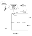
- FIGURE 1 illustrates an example tank level measurement system 100 according to this disclosure.
- the system 100 includes a tank 102 that can store one or more materials 104.
- the tank 102 generally represents any suitable structure for receiving and storing at least one liquid or other material.
- the tank 102 could, for example, represent an oil storage tank or a tank for storing other liquid(s) or other material(s).
- the tank 102 could also have any suitable shape and size.
- the tank 102 could form part of a larger structure.
- the larger structure could represent any fixed or movable structure containing or associated with one or more tanks 102, such as a movable tanker vessel, railcar, or truck or a fixed tank farm.
- a sensor 106 with at least one antenna 108 is used in conjunction with a processing system 110 to measure the level of material 104 in the tank 102.
- the antenna 108 emits electromagnetic waves or other wireless signals towards the material 104 and receives reflected signals from the material 104.
- the sensor 106 includes any suitable structure for generating signals for wireless transmission and for receiving reflected signals.
- the antenna 108 includes any suitable structure for transmitting and/or receiving wireless signals, such as a planar or horn antenna.
- Data from the sensor 106 is provided to the processing system 110.
- the processing system 110 can use the data from the sensor 106 in any suitable manner.
- the sensor 106 could provide data identifying the transmitted and reflected signals, and the processing system 110 can analyze the data to identify the level of the material 104 in the tank 102.
- the processing system 110 could also use the determined level in any suitable manner.
- the processing system 110 could control automatic loading or unloading of the tank 102 by controlling a pump 112 or by providing the determined level to an external controller 114 that controls the pump 112.
- the processing system 110 could also notify personnel responsible for controlling the loading or unloading of the tank 102, such as by displaying the determined level on a display 116 or transmitting the determined level to a wireless or other device 118.
- the processing system 110 could represent any suitable computing or processing system or device, such as a computing device, a process controller, or other system or device.
- the processing system 110 includes at least one processor 120 and at least one memory 122 storing instructions and data used, generated, or collected by the at least one processor 120.
- the processing system 110 can also include at least one interface 124 facilitating communication with external devices or systems like the components 106 and 112-118, such as an Ethernet interface, a radio frequency (RF) or other wireless interface, or a serial interface.
- RF radio frequency
- the sensor 106 generates wireless signals within a desired frequency band with high stability over a wide temperature range.
- PLL phased-lock loop
- STALO PLL-locked stable local oscillator
- This multi-PLL design can provide an extremely flexible architecture to generate very high frequencies that various applications and regulations require.
- This technique can also achieve high stability over a very wide temperature range and achieve better noise performance with fewer components (compared to traditional analog compensation techniques). In particular embodiments, this technique can be applied to radars or other higher-frequency hardware systems that need to provide high performance.
- FIGURE 2 One example implementation of a multi-PLL design that can be used in the sensor 106 is shown in FIGURE 2 , which is described below.
- the "level" of material 104 in a tank 102 could refer to the absolute level of the material 104 in the tank 102, such as when the level represents the distance between the top of the material 104 and the bottom of the tank 102.
- the "level” could also refer to the relative level of the material 104 in the tank 102, such as when the level represents the distance between the top of the material 104 and the antenna 112.
- FIGURE 1 illustrates an example tank level measurement system 100
- the system 100 could include any number of tanks 102, sensors 106, processing systems 110, and other components.
- the functional division shown in FIGURE 1 is for illustration only.
- Various components in FIGURE 1 could be omitted, combined, or further subdivided and additional components could be added according to particular needs.
- the processing system 110 could be integrated into (form a part of) the sensor 106.
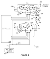
- FIGURE 2 illustrates an example multiple phase-locked loop (PLL) circuit 200 for highly accurate signal generation according to this disclosure. More specifically, this circuit 200 implements a PLL-based stable local oscillator 202, which produces a signal used as an input to a PLL-based control loop 204.
- PLL phase-locked loop
- the PLL-based stable local oscillator 202 includes a voltage-controlled oscillator 206, a first phase-locked loop (PLL1) module 208, a low-pass filter (LPF) 210, and an amplifier 212.
- the voltage-controlled oscillator 206 operates to produce a signal 214, which is provided to the PLL-based control loop 204.
- the voltage-controlled oscillator 206 includes any suitable structure for generating a signal having a frequency based on an input voltage.
- the phase-locked loop module 208, the filter 210, and the amplifier 212 operate to generate a tuning voltage 216 that is provided to the voltage-controlled oscillator 206.
- the phase-locked loop module 208 includes any suitable structure for generating a signal having a stable frequency based on feedback.
- the phase-locked loop module 208 could, for example, include a phase comparator for comparing the phase of the signal 214 to the phase of a signal 218 having a reference frequency (F REF ).
- the filter 210 includes any suitable structure for filtering a signal with an appropriate passband.
- the amplifier 212 includes any suitable structure for providing amplification based on a first control voltage (PLL1 V CTRL ) 220, which in this example is based on the output of the filter 210.
- the control voltage 220 illustrates the flexible control of the tuning range of the voltage-controlled oscillator 206 by the first phase-locked loop module 208.
- the signal 214 produced by the PLL-based stable local oscillator 202 is provided to a buffer 222, which buffers the signal 214.
- the buffered signal 214 is provided to a frequency up-converter 224, which increases the frequency of the buffered signal 214 to produce an up-converted signal 226.
- the frequency up-converter 224 could increase the frequency of the signal 214 by a factor of two or four, although other factors could be used.
- the frequency up-converter 224 represents any suitable structure for increasing the frequency of a signal.
- the up-converted signal 226 is filtered by a bandpass filter (BPF) 228, which includes any suitable structure for filtering a signal with an appropriate passband.
- BPF bandpass filter
- the filtered signal 229 is provided to the PLL-based control loop 204. More specifically, the filtered signal 229 is provided to one input of a mixer 230, which mixes the filtered signal 229 with another signal to produce a mixed signal 232.
- the mixer 230 includes any suitable structure for mixing signals.
- the mixed signal 232 is amplified by an amplifier 234, which represents any suitable structure for providing amplification.
- the PLL-based control loop 204 also includes a voltage-controlled oscillator 236, a second phase-locked loop (PPL2) module 238, a low-pass filter 240, and an amplifier 242 controlled by a second control voltage (PPL2 V CTRL ) 244, which in this example is based on the output of the filter 240.
- the control voltage 244 illustrates the flexible control of the tuning range of the voltage-controlled oscillator 236 by the second phase-locked loop module 238.
- These components 236-242 have the same or similar functionality as the corresponding components 206-212 described above (except the components 236-242 handle signals at higher frequencies).
- the amplifier 242 produces a tuning voltage 243 for the voltage-controlled oscillator 236.
- a signal 246 produced by the voltage-controlled oscillator 236 is provided via a divider, coupler, or splitter 248 to the second input of the mixer 230, as well as to a buffer 250.
- the buffer 250 buffers the signal 246 before providing the buffered signal to a subsequent stage.
- the subsequent stage could represent a stage designed to use the signal 246 for transmission or a stage designed to further increase the frequency of the signal 246.
- the subsequent stage could, for example, include a copy of the components 224-250, where the output of the buffer 250 in FIGURE 2 is coupled to the input of the frequency up-converter 224 in the subsequent stage.
- the output of the circuit 200 can be inserted/cascaded as a STALO for higher frequency up-conversion using the same PLL-based circuit (PLL2 as illustrated). This may be useful when even higher frequencies are desired or required.
- the circuit 200 can be used as an input of direct frequency multiplication or as a direct output to an antenna system for signal radiation.
- the PLL-based stable local oscillator 202 could be used to produce a highly stable 20GHz signal, and the frequency up-converter 224 could use the 20GHz signal to produce a 60GHz or 80GHz signal used by the PLL-based control loop 204.
- Conventional 60GHz or 80GHz free running oscillators are very expensive.
- the use of a dielectric resonance oscillator (DRO) in place of the PLL-based stable local oscillator 202 would allow for the creation of errors, which would lead to the creation of even larger errors in the signal 226 due to the multiplication effect by the frequency up-converter 224.
- DRO dielectric resonance oscillator
- circuit 200 shown in FIGURE 2 helps to overcome drawbacks of using DRO-like oscillators at higher frequencies (since the DRO has temperature-dependent characteristics).
- the circuit 200 shown in FIGURE 2 can generate highly-stable higher-frequency signals using standard off-the-shelf components
- a single frequency reference source 252 (such as a stable local reference oscillator) can be used for all of the PLLs. This may allow the variation of the frequency band caused by the temperature dependence of the reference oscillator to be handled more easily.
- COTS commercial off-the-shelf
- TCXO temperature-compensated crystal oscillator
- ppm parts per million
- the multi-PLL circuit 200 can select a single TCXO as a reference input in a way that the variation of the sweep bandwidth or of the generated frequency can be controlled in a simple manner. This allows higher accuracy of level measurements to be attained.
- a controller 254 provides control signals to at least the phase-locked loop modules 208 and 238.
- each of the phase-locked loop modules 208 and 238 is implemented using a COTS chip, and the controller 254 provides three standard control signals to each phase-locked loop.
- Each phase-locked loop module 208 and 238 can also provide a lock detection signal indicating that a frequency has been locked to the controller 254.
- the controller 254 could control any other aspects of the circuit 200.
- the controller 254 includes any suitable structure for controlling operation of the circuit 200.
- the controller 254 could represent a processor, microprocessor, microcontroller, field programmable gate array, digital signal processor, complex programmable logic device, or other processing or control device.
- the PLL control voltages can be arranged in several ways to produce different frequency modulation schemes and waveforms. For example, to generate a stepped-frequency continuous-wave, one control voltage input can be varied to cover the desired frequency band, and other control voltage input(s) can be fixed as constant(s) to provide a constant STALO frequency signal. As another example, two PLLs may vary in a way that allows a specific frequency coding to be generated. This makes the circuit 200 extremely flexible in locked frequency generation for stepped-frequency continuous-wave radar systems, as well as for other systems (such as frequency hopping).
- One possible modulation scheme involves digital control by the controller 254, which can make higher frequency analog components extremely stable and consistent over a wide range of temperature variations. In this way, the frequencies, bandwidth, and coding sequence can be easily and flexibly adjusted before or during the operation of the circuit 200, such as by programming the controller 254.
- One particular implementation can be used as a software-defined radio system, which can be flexibly accommodated to various national and international regulations.
- FIGURE 2 illustrates an example multiple phase-locked loop circuit 200 for highly accurate signal generation
- various changes may be made to FIGURE 2 .
- multiple stages could be used here, depending on the desired or required frequency of the output signal.
- the implementations of the PLL-based stable local oscillator 202 and the PLL-based control loop 204 are for illustration only.
- FIGURES 3A and 3B illustrate example adjustable power transmission control circuits 300 and 350 using highly accurate signal generation according to this disclosure.
- the adjustable power transmission control circuit 300 includes an amplifier 302, which receives and amplifies a signal provided by a prior stage (such as a signal provided by the circuit 200).
- the amplified signal is provided through a splitter or divider 304 to a variable attenuator 306, which operates to reduce the power of the amplified signal based on a control signal 308 from the controller 254.
- the attenuated signal is then provided via a splitter, coupler, switch, or duplexer 310 to an antenna 312 for transmission.
- the amplified signal from the amplifier 302 is also provided through the splitter or divider 304 to a variable attenuator 314, which also operates to reduce the power of the amplified signal based on a control signal 316 from the controller 254.
- the attenuated signal from the variable attenuator 314 is provided to an amplifier 318, which amplifies the signal as a local oscillator to drive the mixer 320.
- a mixer 320 mixes the amplified signal with received signals provided by the antenna 312 through the splitter, coupler, switch, or duplexer 310.
- a conditioner 319 such as a low noise amplifier (LNA), can be used before the mixer 320 to process the signals provided by the antenna 312.
- LNA low noise amplifier
- the mixed signal produced by the mixer 320 is provided to a bandpass filter 322, which filters the signal.
- the filtered signal can be provided to components in an additional stage, such as an amplifier, a lower-frequency analog-to-digital converter, or other components in the "receive path" of a device.
- Each of the variable attenuators 306 and 314 includes any suitable structure for providing variable attenuation controlled separately by a controller.
- Each of the amplifiers 302 and 318 includes any suitable structure for providing amplification.
- Each of the splitters, couplers, switches, duplexers, or dividers 304 and 310 includes any suitable structure for dividing access to one or more components.
- the antenna 312 includes any suitable structure for transmitting and/or receiving wireless signals.
- the mixer 320 includes any suitable structure for mixing signals.
- the filter 322 includes any suitable structure for filtering a signal with an appropriate passband.
- the adjustable power transmission control circuit 350 includes many of the same components 352-358 and 362-372 as shown in FIGURE 3A .
- the variable attenuator 356 is provided with an additional amplifier 374. This combination can also be used to compensate for some upper spectral loss.
- a directional coupler 360 is used to provide an input to the mixer 370.
- a portion of the energy transmitted to or from the antenna 362 can be coupled to the mixer 370 by the directional coupler 360.
- variable attenuators are used and controlled by the controller 254.
- the variable attenuators are used to control both the radiated power level of a device and the processing of received signals.
- the radiated power level of the device can be set in accordance with different applications, environments, and regulations. Since both the frequency spectrum and the power of the generated signals can be digitally controlled, radar systems and other systems can be made more flexible and accurate with consistent performance.
- FIGURES 3A and 3B illustrate example adjustable power transmission control circuits 300 and 350 using highly accurate signal generation
- the controller in FIGURES 3A and 3B need not necessarily represent the same controller 254 used in FIGURE 2 .
- a highly accurate signal is used here for both transmission and reception, the highly accurate signal from the prior stage could be used for either transmission or reception.
- a device could include only a transmission path or only a receive path if the device represents a transmit-only device or a receive-only device.
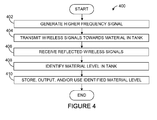
- FIGURE 4 illustrates an example method 400 for level gauging using highly accurate signal generation according to this disclosure.
- an accurate higher-frequency signal is generated at step 402. This could include, for example, the sensor 106 using the multiple PLL circuit 200 of FIGURE 2 to generate a 20GHz, 60GHZ, or 80GHz wideband signal with high accuracy, regardless of temperature or transmission power level.
- Wireless signals are transmitted towards material in a tank at step 404, and reflected signals are received at step 406.
- This could include, for example, the sensor 106 generating wireless signals that are transmitted from the antenna 108 towards the material 104 in the tank 102 and receiving wireless signals reflected from, among other things, the material 104.
- the wireless signals transmitted to the material 104 could be generated using the highly accurate signal produced at step 402, and/or the wireless signals received from the material 104 could be processed using the highly accurate signal produced at step 402.
- the level of material in the tank is identified at step 408. This could include, for example, the processing system 110 using time of flight or other techniques used in level gauges to calculate the level of material 104 in the tank 102.
- the identified level is stored, output, and/or used in any suitable manner at step 410. This could include, for example, the processing system 110 displaying the identified level, storing the identified level in a memory, or transmitting messages containing the identified level.
- FIGURE 4 illustrates an example method 400 for level gauging using highly accurate signal generation
- various changes may be made to FIGURE 4 .
- steps in FIGURE 4 may overlap, occur in parallel, or occur multiple times.
- FIGURE 5 illustrates an example method 500 for highly accurate signal generation according to this disclosure.
- a reference signal identifying a reference frequency is received at step 502. This could include, for example, the circuit 200 receiving the signal 218 defining a reference frequency.
- a first signal is generated at a lower frequency using a stable local oscillator with a first PLL at step 504.
- the signal 214 is generated by the voltage-controlled oscillator 206 using the phase-locked loop module 208, which receives the reference signal identifying the reference frequency.
- a second signal is generated using frequency up-conversion and the first signal at step 506.
- the frequency of the signal 214 could be increased by any suitable factor.
- the second signal is provided to a control loop with a second PLL at step 508. This could include, for example, providing the signal 226 to the mixer 230 in the PLL-based control loop 204.
- a third signal is generated at a higher frequency using the control loop at step 510.
- the signal 246 is generated by the voltage-controlled oscillator 236 using the phase-locked loop module 238, which receives the reference signal identifying the reference frequency.
- the third signal is output at step 512. This could include, for example, providing the signal 246 to one of the circuits 300 or 350 in FIGURE 3A or 3B or to any other suitable component or system.
- FIGURE 5 illustrates an example method 500 for highly accurate signal generation
- various changes may be made to FIGURE 5 .
- steps in FIGURE 5 may overlap, occur in parallel, or occur multiple times.
- various functions described above are implemented or supported by a computer program that is formed from computer readable program code and that is embodied in a computer readable medium.
- computer readable program code includes any type of computer code, including source code, object code, and executable code.
- computer readable medium includes any type of medium capable of being accessed by a computer, such as read only memory (ROM), random access memory (RAM), a hard disk drive, a compact disc (CD), a digital video disc (DVD), or any other type of memory.
- the terms “higher” and “lower” refer to relative values (such as relative frequencies) and do not involve any specific values or ranges of values.
- the term “couple” and its derivatives refer to any direct or indirect communication between two or more elements, whether or not those elements are in physical contact with one another.
- the terms “algorithm” and “program” refers to one or more computer programs, software components, sets of instructions, procedures, functions, objects, classes, instances, related data, or a portion thereof adapted for implementation in a suitable computer code (including source code, object code, or executable code).
- controller means any device, system, or part thereof that controls at least one operation.
- a controller may be implemented in hardware, firmware, software, or some combination of at least two of the same. The functionality associated with any particular controller may be centralized or distributed, whether locally or remotely.
Abstract
Description
- This application claims priority under 35 U.S.C. § 119(e) to
U.S. Provisional Application No. 61/098,146 filed on September 18, 2008 - This disclosure relates generally to inventory management systems. More specifically, this disclosure relates to a method and apparatus for highly accurate higher frequency signal generation and related level gauge.
- Processing facilities and other facilities routinely include tanks for storing liquid materials and other materials. For example, storage tanks are routinely used in tank farm facilities and other storage facilities to store oil or other materials. As another example, oil tankers and other transport vessels routinely include numerous tanks storing oil or other materials.
- Often times, it is necessary or desirable to measure the amount of material stored in a tank. This may be useful, for example, during custody transfer applications when material is being transferred from one party to another, such as from a seller to a buyer. During these types of applications, the amount of material in a tank often must be measured with high precision. In bulk storage tanks, an error of one millimeter in a level reading can correspond to several cubic meters of volumetric error. This can result in losses of thousands of dollars for one or more parties. High-precision measurements often require high accuracy (such as ±1mm) over a wide range of temperatures (such as -40°F to +185°F).
- One approach to measuring the amount of material in a tank involves the use of radar measurements. In this approach, radar signals are transmitted towards and reflected off the surface of the material in the tank. Radar accuracy is often directly associated with the stability of frequency signal generation. However, radar signals are often generated using voltage-controlled oscillators (VCOs), and voltage-controlled oscillators typically suffer from ambient temperature variations and high noise levels, particularly when used with higher-frequency electromagnetic waves such as millimeter waves (MMW). As a result, analog components and circuits often need to implement complicated compensation circuitry to cope with temperature variations and time drifts that occur during the frequency signal generation. These traditional solutions are often expensive and sometimes awkward, especially for frequencies higher than 20GHz.
- A phase-locked loop (PLL) can be used to stabilize a voltage-controlled oscillator by forming a closed loop so that a frequency produced by the voltage-controlled oscillator is relatively stable or "locked." This solution is effective if the frequency range of the voltage-controlled oscillator can be covered by the phase-locked loop's bandwidth. This is typically true for the frequency range below 10GHz because of limitations of current phase-locked loop chips. For frequencies higher than 10GHz, a dielectric resonance oscillator (DRO) is often adopted as a local oscillator to down-convert higher frequencies to lower frequencies that can match a phase-locked loop's tuning range. However, dielectric resonance oscillators are still susceptible to temperature variations, which results in variations of the locked frequencies. This also introduces errors in signal processing using signal frequency and/or bandwidth information. One reason for using higher frequencies in radar level gauging technologies is that national and international regulations may limit the use of larger bandwidths at lower frequencies. These regulatory constraints can have a negative impact on high precision radar level measurements.
- This disclosure provides a method and apparatus for highly accurate higher frequency signal generation and related level gauge.
- In a first embodiment, an apparatus includes a stable local oscillator, which includes a first control loop. The first control loop includes (i) a first voltage-controlled oscillator configured to generate a first output signal and (ii) a first phase-locked loop. The apparatus also includes a frequency up-converter configured to increase a frequency of the first output signal. The apparatus further includes a second control loop configured to receive the up-converted first output signal. The second control loop includes (i) a second voltage-controlled oscillator configured to generate a second output signal and (ii) a second phase-locked loop.
- In a second embodiment, a level gauge includes a sensor configured to transmit wireless signals towards material in a tank and receive wireless signals reflected off the material in the tank. The level gauge also includes a processing system configured to identify a level of the material in the tank based on the wireless signals transmitted towards and reflected off the material in the tank. The sensor includes a phase-locked loop based stable local oscillator configured to generate a first output signal and a phase-locked loop based control loop configured to generate a second output signal based on the first output signal.
- In a third embodiment, a method includes generating a first signal using a stable local oscillator that includes a first control loop. The first control loop includes a first voltage-controlled oscillator and a first phase-locked loop. The method also includes increasing a frequency of the first signal to produce an up-converted first signal. The method further includes generating a second signal based on the up-converted first signal using a second control loop. The second control loop includes a second voltage-controlled oscillator and a second phase-locked loop.
- Other technical features may be readily apparent to one skilled in the art from the following figures, descriptions, and claims.
- For a more complete understanding of this disclosure and its features, reference is now made to the following description, taken in conjunction with the accompanying drawings, in which:
-
FIGURE 1 illustrates an example tank level measurement system according to this disclosure; -
FIGURE 2 illustrates an example multiple phase-locked loop (PLL) circuit for highly accurate signal generation according to this disclosure; -
FIGURES 3A and 3B illustrate example adjustable power transmission control circuits using highly accurate signal generation according to this disclosure; -
FIGURE 4 illustrates an example method for level gauging using highly accurate signal generation according to this disclosure; and -
FIGURE 5 illustrates an example method for highly accurate signal generation according to this disclosure. -
FIGURES 1 through 5 , discussed below, and the various embodiments used to describe the principles of the present invention in this patent document are by way of illustration only and should not be construed in any way to limit the scope of the invention. Those skilled in the art will understand that the principles of the invention may be implemented in any type of suitably arranged device or system. -
FIGURE 1 illustrates an example tanklevel measurement system 100 according to this disclosure. In this example, thesystem 100 includes atank 102 that can store one ormore materials 104. Thetank 102 generally represents any suitable structure for receiving and storing at least one liquid or other material. Thetank 102 could, for example, represent an oil storage tank or a tank for storing other liquid(s) or other material(s). Thetank 102 could also have any suitable shape and size. Further, thetank 102 could form part of a larger structure. The larger structure could represent any fixed or movable structure containing or associated with one ormore tanks 102, such as a movable tanker vessel, railcar, or truck or a fixed tank farm. - A
sensor 106 with at least oneantenna 108 is used in conjunction with aprocessing system 110 to measure the level ofmaterial 104 in thetank 102. Theantenna 108 emits electromagnetic waves or other wireless signals towards thematerial 104 and receives reflected signals from thematerial 104. Thesensor 106 includes any suitable structure for generating signals for wireless transmission and for receiving reflected signals. Theantenna 108 includes any suitable structure for transmitting and/or receiving wireless signals, such as a planar or horn antenna. - Data from the
sensor 106 is provided to theprocessing system 110. Theprocessing system 110 can use the data from thesensor 106 in any suitable manner. For example, thesensor 106 could provide data identifying the transmitted and reflected signals, and theprocessing system 110 can analyze the data to identify the level of the material 104 in thetank 102. Theprocessing system 110 could also use the determined level in any suitable manner. For example, theprocessing system 110 could control automatic loading or unloading of thetank 102 by controlling apump 112 or by providing the determined level to anexternal controller 114 that controls thepump 112. Theprocessing system 110 could also notify personnel responsible for controlling the loading or unloading of thetank 102, such as by displaying the determined level on adisplay 116 or transmitting the determined level to a wireless orother device 118. - The
processing system 110 could represent any suitable computing or processing system or device, such as a computing device, a process controller, or other system or device. In particular embodiments, theprocessing system 110 includes at least oneprocessor 120 and at least onememory 122 storing instructions and data used, generated, or collected by the at least oneprocessor 120. Theprocessing system 110 can also include at least oneinterface 124 facilitating communication with external devices or systems like thecomponents 106 and 112-118, such as an Ethernet interface, a radio frequency (RF) or other wireless interface, or a serial interface. - In one aspect of operation, the
sensor 106 generates wireless signals within a desired frequency band with high stability over a wide temperature range. This can be done using a multiple phased-lock loop (PLL) scheme for higher frequency generation (such as for millimeter waves). For example, a PLL-locked stable local oscillator (STALO) can be used, where frequency up-conversion is controlled by additional PLL-locking circuitry. This multi-PLL design can provide an extremely flexible architecture to generate very high frequencies that various applications and regulations require. This technique can also achieve high stability over a very wide temperature range and achieve better noise performance with fewer components (compared to traditional analog compensation techniques). In particular embodiments, this technique can be applied to radars or other higher-frequency hardware systems that need to provide high performance. One example implementation of a multi-PLL design that can be used in thesensor 106 is shown inFIGURE 2 , which is described below. - Note that the "level" of
material 104 in atank 102 could refer to the absolute level of the material 104 in thetank 102, such as when the level represents the distance between the top of thematerial 104 and the bottom of thetank 102. The "level" could also refer to the relative level of the material 104 in thetank 102, such as when the level represents the distance between the top of thematerial 104 and theantenna 112. - Although
FIGURE 1 illustrates an example tanklevel measurement system 100, various changes may be made toFIGURE 1 . For example, thesystem 100 could include any number oftanks 102,sensors 106,processing systems 110, and other components. Also, the functional division shown inFIGURE 1 is for illustration only. Various components inFIGURE 1 could be omitted, combined, or further subdivided and additional components could be added according to particular needs. As a particular example, theprocessing system 110 could be integrated into (form a part of) thesensor 106. -
FIGURE 2 illustrates an example multiple phase-locked loop (PLL)circuit 200 for highly accurate signal generation according to this disclosure. More specifically, thiscircuit 200 implements a PLL-based stablelocal oscillator 202, which produces a signal used as an input to a PLL-basedcontrol loop 204. - As shown in
FIGURE 2 , the PLL-based stablelocal oscillator 202 includes a voltage-controlledoscillator 206, a first phase-locked loop (PLL1)module 208, a low-pass filter (LPF) 210, and anamplifier 212. The voltage-controlledoscillator 206 operates to produce asignal 214, which is provided to the PLL-basedcontrol loop 204. The voltage-controlledoscillator 206 includes any suitable structure for generating a signal having a frequency based on an input voltage. - The phase-locked
loop module 208, thefilter 210, and theamplifier 212 operate to generate atuning voltage 216 that is provided to the voltage-controlledoscillator 206. The phase-lockedloop module 208 includes any suitable structure for generating a signal having a stable frequency based on feedback. The phase-lockedloop module 208 could, for example, include a phase comparator for comparing the phase of thesignal 214 to the phase of asignal 218 having a reference frequency (FREF). Thefilter 210 includes any suitable structure for filtering a signal with an appropriate passband. Theamplifier 212 includes any suitable structure for providing amplification based on a first control voltage (PLL1 VCTRL) 220, which in this example is based on the output of thefilter 210. Thecontrol voltage 220 illustrates the flexible control of the tuning range of the voltage-controlledoscillator 206 by the first phase-lockedloop module 208. - The
signal 214 produced by the PLL-based stablelocal oscillator 202 is provided to abuffer 222, which buffers thesignal 214. Thebuffered signal 214 is provided to a frequency up-converter 224, which increases the frequency of thebuffered signal 214 to produce an up-convertedsignal 226. For example, the frequency up-converter 224 could increase the frequency of thesignal 214 by a factor of two or four, although other factors could be used. The frequency up-converter 224 represents any suitable structure for increasing the frequency of a signal. The up-convertedsignal 226 is filtered by a bandpass filter (BPF) 228, which includes any suitable structure for filtering a signal with an appropriate passband. - The filtered
signal 229 is provided to the PLL-basedcontrol loop 204. More specifically, the filteredsignal 229 is provided to one input of amixer 230, which mixes the filteredsignal 229 with another signal to produce amixed signal 232. Themixer 230 includes any suitable structure for mixing signals. Themixed signal 232 is amplified by anamplifier 234, which represents any suitable structure for providing amplification. - The PLL-based
control loop 204 also includes a voltage-controlledoscillator 236, a second phase-locked loop (PPL2)module 238, a low-pass filter 240, and anamplifier 242 controlled by a second control voltage (PPL2 VCTRL) 244, which in this example is based on the output of thefilter 240. Thecontrol voltage 244 illustrates the flexible control of the tuning range of the voltage-controlledoscillator 236 by the second phase-lockedloop module 238. These components 236-242 have the same or similar functionality as the corresponding components 206-212 described above (except the components 236-242 handle signals at higher frequencies). Theamplifier 242 produces atuning voltage 243 for the voltage-controlledoscillator 236. - A
signal 246 produced by the voltage-controlledoscillator 236 is provided via a divider, coupler, orsplitter 248 to the second input of themixer 230, as well as to abuffer 250. Thebuffer 250 buffers thesignal 246 before providing the buffered signal to a subsequent stage. The subsequent stage could represent a stage designed to use thesignal 246 for transmission or a stage designed to further increase the frequency of thesignal 246. The subsequent stage could, for example, include a copy of the components 224-250, where the output of thebuffer 250 inFIGURE 2 is coupled to the input of the frequency up-converter 224 in the subsequent stage. In other words, the output of thecircuit 200 can be inserted/cascaded as a STALO for higher frequency up-conversion using the same PLL-based circuit (PLL2 as illustrated). This may be useful when even higher frequencies are desired or required. In other embodiments, thecircuit 200 can be used as an input of direct frequency multiplication or as a direct output to an antenna system for signal radiation. - As a particular example, the PLL-based stable
local oscillator 202 could be used to produce a highly stable 20GHz signal, and the frequency up-converter 224 could use the 20GHz signal to produce a 60GHz or 80GHz signal used by the PLL-basedcontrol loop 204. Conventional 60GHz or 80GHz free running oscillators are very expensive. Also, the use of a dielectric resonance oscillator (DRO) in place of the PLL-based stablelocal oscillator 202 would allow for the creation of errors, which would lead to the creation of even larger errors in thesignal 226 due to the multiplication effect by the frequency up-converter 224. In contrast, thecircuit 200 shown inFIGURE 2 helps to overcome drawbacks of using DRO-like oscillators at higher frequencies (since the DRO has temperature-dependent characteristics). Thecircuit 200 shown inFIGURE 2 can generate highly-stable higher-frequency signals using standard off-the-shelf components - To keep the
multiple PLL modules FIGURE 2 under control, a single frequency reference source 252 (such as a stable local reference oscillator) can be used for all of the PLLs. This may allow the variation of the frequency band caused by the temperature dependence of the reference oscillator to be handled more easily. Commercial off-the-shelf (COTS) components of a temperature-compensated crystal oscillator (TCXO) with few parts per million (ppm) are widely available on the market, which can ensure a higher measuring accuracy in level gauges (such as ±1mm). As a result, themulti-PLL circuit 200 can select a single TCXO as a reference input in a way that the variation of the sweep bandwidth or of the generated frequency can be controlled in a simple manner. This allows higher accuracy of level measurements to be attained. - In this example, a
controller 254 provides control signals to at least the phase-lockedloop modules loop modules controller 254 provides three standard control signals to each phase-locked loop. Each phase-lockedloop module controller 254. Thecontroller 254 could control any other aspects of thecircuit 200. Thecontroller 254 includes any suitable structure for controlling operation of thecircuit 200. As particular examples, thecontroller 254 could represent a processor, microprocessor, microcontroller, field programmable gate array, digital signal processor, complex programmable logic device, or other processing or control device. - The PLL control voltages (including
voltages filters 210 and 240) can be arranged in several ways to produce different frequency modulation schemes and waveforms. For example, to generate a stepped-frequency continuous-wave, one control voltage input can be varied to cover the desired frequency band, and other control voltage input(s) can be fixed as constant(s) to provide a constant STALO frequency signal. As another example, two PLLs may vary in a way that allows a specific frequency coding to be generated. This makes thecircuit 200 extremely flexible in locked frequency generation for stepped-frequency continuous-wave radar systems, as well as for other systems (such as frequency hopping). - One possible modulation scheme involves digital control by the
controller 254, which can make higher frequency analog components extremely stable and consistent over a wide range of temperature variations. In this way, the frequencies, bandwidth, and coding sequence can be easily and flexibly adjusted before or during the operation of thecircuit 200, such as by programming thecontroller 254. One particular implementation can be used as a software-defined radio system, which can be flexibly accommodated to various national and international regulations. - Although
FIGURE 2 illustrates an example multiple phase-lockedloop circuit 200 for highly accurate signal generation, various changes may be made toFIGURE 2 . For example, as noted above, multiple stages could be used here, depending on the desired or required frequency of the output signal. Also, the implementations of the PLL-based stablelocal oscillator 202 and the PLL-basedcontrol loop 204 are for illustration only. -
FIGURES 3A and 3B illustrate example adjustable powertransmission control circuits FIGURE 3A , the adjustable powertransmission control circuit 300 includes anamplifier 302, which receives and amplifies a signal provided by a prior stage (such as a signal provided by the circuit 200). The amplified signal is provided through a splitter ordivider 304 to avariable attenuator 306, which operates to reduce the power of the amplified signal based on acontrol signal 308 from thecontroller 254. The attenuated signal is then provided via a splitter, coupler, switch, orduplexer 310 to anantenna 312 for transmission. - The amplified signal from the
amplifier 302 is also provided through the splitter ordivider 304 to avariable attenuator 314, which also operates to reduce the power of the amplified signal based on acontrol signal 316 from thecontroller 254. The attenuated signal from thevariable attenuator 314 is provided to anamplifier 318, which amplifies the signal as a local oscillator to drive themixer 320. Amixer 320 mixes the amplified signal with received signals provided by theantenna 312 through the splitter, coupler, switch, orduplexer 310. Aconditioner 319, such as a low noise amplifier (LNA), can be used before themixer 320 to process the signals provided by theantenna 312. The mixed signal produced by themixer 320 is provided to abandpass filter 322, which filters the signal. The filtered signal can be provided to components in an additional stage, such as an amplifier, a lower-frequency analog-to-digital converter, or other components in the "receive path" of a device. - Each of the
variable attenuators amplifiers dividers antenna 312 includes any suitable structure for transmitting and/or receiving wireless signals. Themixer 320 includes any suitable structure for mixing signals. Thefilter 322 includes any suitable structure for filtering a signal with an appropriate passband. - As shown in
FIGURE 3B , the adjustable powertransmission control circuit 350 includes many of the same components 352-358 and 362-372 as shown inFIGURE 3A . InFIGURE 3B , however, thevariable attenuator 356 is provided with anadditional amplifier 374. This combination can also be used to compensate for some upper spectral loss. Also, adirectional coupler 360 is used to provide an input to themixer 370. Here, a portion of the energy transmitted to or from theantenna 362 can be coupled to themixer 370 by thedirectional coupler 360. - In the embodiments shown in
FIGURES 3A and 3B , one or more variable attenuators are used and controlled by thecontroller 254. Here, the variable attenuators are used to control both the radiated power level of a device and the processing of received signals. The radiated power level of the device can be set in accordance with different applications, environments, and regulations. Since both the frequency spectrum and the power of the generated signals can be digitally controlled, radar systems and other systems can be made more flexible and accurate with consistent performance. - Although
FIGURES 3A and 3B illustrate example adjustable powertransmission control circuits FIGURES 3A and 3B . For example, the controller inFIGURES 3A and 3B need not necessarily represent thesame controller 254 used inFIGURE 2 . Also, while a highly accurate signal is used here for both transmission and reception, the highly accurate signal from the prior stage could be used for either transmission or reception. In fact, a device could include only a transmission path or only a receive path if the device represents a transmit-only device or a receive-only device. -
FIGURE 4 illustrates anexample method 400 for level gauging using highly accurate signal generation according to this disclosure. As shown inFIGURE 4 , an accurate higher-frequency signal is generated atstep 402. This could include, for example, thesensor 106 using themultiple PLL circuit 200 ofFIGURE 2 to generate a 20GHz, 60GHZ, or 80GHz wideband signal with high accuracy, regardless of temperature or transmission power level. - Wireless signals are transmitted towards material in a tank at
step 404, and reflected signals are received atstep 406. This could include, for example, thesensor 106 generating wireless signals that are transmitted from theantenna 108 towards thematerial 104 in thetank 102 and receiving wireless signals reflected from, among other things, thematerial 104. The wireless signals transmitted to thematerial 104 could be generated using the highly accurate signal produced atstep 402, and/or the wireless signals received from thematerial 104 could be processed using the highly accurate signal produced atstep 402. - The level of material in the tank is identified at
step 408. This could include, for example, theprocessing system 110 using time of flight or other techniques used in level gauges to calculate the level ofmaterial 104 in thetank 102. The identified level is stored, output, and/or used in any suitable manner atstep 410. This could include, for example, theprocessing system 110 displaying the identified level, storing the identified level in a memory, or transmitting messages containing the identified level. - Although
FIGURE 4 illustrates anexample method 400 for level gauging using highly accurate signal generation, various changes may be made toFIGURE 4 . For example, while shown as a series of steps, various steps inFIGURE 4 may overlap, occur in parallel, or occur multiple times. -
FIGURE 5 illustrates anexample method 500 for highly accurate signal generation according to this disclosure. As shown inFIGURE 5 , a reference signal identifying a reference frequency is received atstep 502. This could include, for example, thecircuit 200 receiving thesignal 218 defining a reference frequency. - A first signal is generated at a lower frequency using a stable local oscillator with a first PLL at
step 504. This could include, for example, thecircuit 200 generating thesignal 214 using the PLL-based stablelocal oscillator 202. Thesignal 214 is generated by the voltage-controlledoscillator 206 using the phase-lockedloop module 208, which receives the reference signal identifying the reference frequency. - A second signal is generated using frequency up-conversion and the first signal at
step 506. This could include, for example, thecircuit 200 using the frequency up-converter 224 to increase the frequency of thesignal 214 to produce thesignal 226. The frequency of thesignal 214 could be increased by any suitable factor. - The second signal is provided to a control loop with a second PLL at
step 508. This could include, for example, providing thesignal 226 to themixer 230 in the PLL-basedcontrol loop 204. - A third signal is generated at a higher frequency using the control loop at
step 510. This could include, for example, thecircuit 200 generating thesignal 246 using the PLL-basedcontrol loop 204. Thesignal 246 is generated by the voltage-controlledoscillator 236 using the phase-lockedloop module 238, which receives the reference signal identifying the reference frequency. - The third signal is output at
step 512. This could include, for example, providing thesignal 246 to one of thecircuits FIGURE 3A or 3B or to any other suitable component or system. - Although
FIGURE 5 illustrates anexample method 500 for highly accurate signal generation, various changes may be made toFIGURE 5 . For example, while shown as a series of steps, various steps inFIGURE 5 may overlap, occur in parallel, or occur multiple times. - In some embodiments, various functions described above are implemented or supported by a computer program that is formed from computer readable program code and that is embodied in a computer readable medium. The phrase "computer readable program code" includes any type of computer code, including source code, object code, and executable code. The phrase "computer readable medium" includes any type of medium capable of being accessed by a computer, such as read only memory (ROM), random access memory (RAM), a hard disk drive, a compact disc (CD), a digital video disc (DVD), or any other type of memory.
- It may be advantageous to set forth definitions of certain words and phrases used throughout this patent document. The terms "higher" and "lower" refer to relative values (such as relative frequencies) and do not involve any specific values or ranges of values. The term "couple" and its derivatives refer to any direct or indirect communication between two or more elements, whether or not those elements are in physical contact with one another. The terms "algorithm" and "program" refers to one or more computer programs, software components, sets of instructions, procedures, functions, objects, classes, instances, related data, or a portion thereof adapted for implementation in a suitable computer code (including source code, object code, or executable code). The terms "transmit," "receive," and "communicate," as well as derivatives thereof, encompass both direct and indirect communication. The terms "include" and "comprise," as well as derivatives thereof, mean inclusion without limitation. The term "or" is inclusive, meaning and/or. The phrases "associated with" and "associated therewith," as well as derivatives thereof, may mean to include, be included within, interconnect with, contain, be contained within, connect to or with, couple to or with, be communicable with, cooperate with, interleave, juxtapose, be proximate to, be bound to or with, have, have a property of, or the like. The term "controller" means any device, system, or part thereof that controls at least one operation. A controller may be implemented in hardware, firmware, software, or some combination of at least two of the same. The functionality associated with any particular controller may be centralized or distributed, whether locally or remotely.
- While this disclosure has described certain embodiments and generally associated methods, alterations and permutations of these embodiments and methods will be apparent to those skilled in the art. Accordingly, the above description of example embodiments does not define or constrain this disclosure. Other changes, substitutions, and alterations are also possible without departing from the spirit and scope of this disclosure, as defined by the following claims.
Claims (10)
- An apparatus comprising:a stable local oscillator (202) comprising a first control loop, the first control loop comprising (i) a first voltage-controlled oscillator (206) configured to generate a first output signal (214) and (ii) a first phase-locked loop (208);a frequency up-converter (224) configured to increase a frequency of the first output signal; anda second control loop (204) configured to receive the up-converted first output signal, the second control loop comprising (i) a second voltage-controlled oscillator (236) configured to generate a second output signal (246) and (ii) a second phase-locked loop (238).
- The apparatus of Claim 1, wherein the second control loop further comprises:a mixer (230) having a first input coupled to the frequency up-converter, a second input coupled to the second voltage-controlled oscillator, and an output coupled to the second phase-locked loop.
- The apparatus of Claim 1, further comprising:a reference frequency source (252) configured to generate a signal (218) identifying a reference frequency and to provide the signal identifying the reference frequency to the first and second phase-locked loops.
- The apparatus of Claim 1, further comprising:an amplifier (302, 352) configured to receive and amplify the second output signal; anda variable attenuator (306, 314, 356, 364) configured to receive and attenuate the amplified second output signal.
- The apparatus of Claim 4, wherein the variable attenuator (306, 356) is coupled to an antenna (312, 362) configured to transmit wireless signals based on the attenuated second output signal.
- The apparatus of Claim 4, wherein the variable attenuator (314, 364) is coupled to a mixer (320, 370) configured to mix the attenuated second output signal with signals from one of: an antenna (312) and a directional coupler (360).
- The apparatus of Claim 1, wherein the second control loop forms part of a first stage; and
further comprising a second stage configured to receive the second output signal and generate a higher-frequency third output signal, the second stage comprising a third control loop, the third control loop comprising (i) a third voltage-controlled oscillator configured to generate the third output signal and (ii) a third phase-locked loop. - A level gauge comprising:a sensor (106) configured to transmit wireless signals towards material (104) in a tank (102) and receive wireless signals reflected off the material in the tank; anda processing system (110) configured to identify a level of the material in the tank based on the wireless signals transmitted towards and reflected off the material in the tank;wherein the sensor comprises:a phase-locked loop based stable local oscillator (202) configured to generate a first output signal (214); anda phase-locked loop based control loop (204) configured to generate a second output signal (246) based on the first output signal.
- The level gauge of Claim 8, wherein:the phase-locked loop based stable local oscillator comprises (i) a first voltage-controlled oscillator (206) configured to generate the first output signal and (ii) a first phase-locked loop (208);the sensor further comprises a frequency up-converter (224) configured to increase a frequency of the first output signal; andthe phase-locked loop based control loop is configured to receive the up-converted first output signal, the control loop comprising (i) a second voltage-controlled oscillator (236) configured to generate the second output signal and (ii) a second phase-locked loop (238).
- A method comprising:generating (504) a first signal (214) using a stable local oscillator (202) that comprises a first control loop, the first control loop comprising a first voltage-controlled oscillator (206) and a first phase-locked loop (208);increasing (506) a frequency of the first signal to produce an up-converted first signal; andgenerating (510) a second signal based on the up-converted first signal using a second control loop (204), the second control loop comprising a second voltage-controlled oscillator (236) and a second phase-locked loop (238).
Applications Claiming Priority (2)
| Application Number | Priority Date | Filing Date | Title |
|---|---|---|---|
| US9814608P | 2008-09-18 | 2008-09-18 | |
| US12/534,723 US8659472B2 (en) | 2008-09-18 | 2009-08-03 | Method and apparatus for highly accurate higher frequency signal generation and related level gauge |
Publications (3)
| Publication Number | Publication Date |
|---|---|
| EP2166671A2 true EP2166671A2 (en) | 2010-03-24 |
| EP2166671A3 EP2166671A3 (en) | 2010-04-28 |
| EP2166671B1 EP2166671B1 (en) | 2012-03-21 |
Family
ID=41350679
Family Applications (1)
| Application Number | Title | Priority Date | Filing Date |
|---|---|---|---|
| EP09169962A Active EP2166671B1 (en) | 2008-09-18 | 2009-09-10 | Method and apparatus for highly accurate higher frequency signal generation and related level gauge |
Country Status (3)
| Country | Link |
|---|---|
| US (1) | US8659472B2 (en) |
| EP (1) | EP2166671B1 (en) |
| AT (1) | ATE550831T1 (en) |
Cited By (10)
| Publication number | Priority date | Publication date | Assignee | Title |
|---|---|---|---|---|
| WO2013044953A1 (en) * | 2011-09-27 | 2013-04-04 | Rosemount Tank Radar Ab | Radar level gauging with detection of moving surface |
| US8730093B2 (en) | 2011-09-27 | 2014-05-20 | Rosemount Tank Radar Ab | MFPW radar level gauging with distance approximation |
| WO2014135565A1 (en) * | 2013-03-07 | 2014-09-12 | Rosemount Tank Radar Ab | Fmcw radar level gauge with lock state control |
| US8872694B2 (en) | 2010-12-30 | 2014-10-28 | Rosemount Tank Radar Ab | Radar level gauging using frequency modulated pulsed wave |
| US9513153B2 (en) | 2010-12-30 | 2016-12-06 | Rosemount Tank Radar Ab | Radar level gauging using frequency modulated pulsed wave |
| EP3255392A1 (en) * | 2016-06-07 | 2017-12-13 | VEGA Grieshaber KG | Fill level radar for beam forming using parallel plls from the transmitter side |
| US20180031687A1 (en) * | 2016-08-01 | 2018-02-01 | Vega Grieshaber Kg | Radar fill level measurement device |
| CN108871500A (en) * | 2017-05-09 | 2018-11-23 | Vega格里沙贝两合公司 | Radar apparatus for measuring charge level including phaselocked loop and application thereof and operating method |
| EP3418699A1 (en) * | 2017-06-21 | 2018-12-26 | VEGA Grieshaber KG | Fill level radar device with controlled transmission power |
| US10866134B2 (en) | 2017-06-21 | 2020-12-15 | Vega Grieshaber Kg | Fill level measurement device having optimised energy consumption |
Families Citing this family (14)
| Publication number | Priority date | Publication date | Assignee | Title |
|---|---|---|---|---|
| NL1031209C2 (en) * | 2006-02-22 | 2007-08-24 | Enraf Bv | Method and device for accurately determining the level L of a liquid with the aid of radar signals radiated to the liquid level and radar signals reflected by the liquid level. |
| NL1034327C2 (en) * | 2007-09-04 | 2009-03-05 | Enraf Bv | Method and device for determining the level L of a liquid within a certain measuring range with the aid of radar signals radiated to the liquid level and radar signals reflected by the liquid level. |
| US8224594B2 (en) * | 2008-09-18 | 2012-07-17 | Enraf B.V. | Apparatus and method for dynamic peak detection, identification, and tracking in level gauging applications |
| US8271212B2 (en) * | 2008-09-18 | 2012-09-18 | Enraf B.V. | Method for robust gauging accuracy for level gauges under mismatch and large opening effects in stillpipes and related apparatus |
| WO2013067594A1 (en) * | 2011-11-11 | 2013-05-16 | The University Of Melbourne | An apparatus and a method for obtaining information about at least one target |
| US9046406B2 (en) | 2012-04-11 | 2015-06-02 | Honeywell International Inc. | Advanced antenna protection for radars in level gauging and other applications |
| US9991751B2 (en) | 2014-05-09 | 2018-06-05 | The Board Of Trustees Of The Leland Stanford Junior University | Short range wireless communication |
| DE102014111431A1 (en) * | 2014-08-11 | 2016-02-11 | Infineon Technologies Ag | Flight time devices and a lighting source |
| CN104655184B (en) * | 2014-12-19 | 2017-09-19 | 山东应天节能环保科技有限公司 | Desulphurization denitration material flow and allowance detector and method based on 3D radars |
| US9701323B2 (en) | 2015-04-06 | 2017-07-11 | Bedloe Industries Llc | Railcar coupler |
| JP6394797B2 (en) * | 2015-04-24 | 2018-09-26 | 三菱電機株式会社 | Frequency synchronization apparatus and frequency synchronization system |
| DE102015219612A1 (en) * | 2015-10-09 | 2017-04-13 | Vega Grieshaber Kg | System architecture for a MIMO level radar |
| DE102017207783B3 (en) * | 2017-05-09 | 2018-06-07 | Vega Grieshaber Kg | Radar level gauge with a phase locked loop |
| US10914830B2 (en) * | 2017-10-12 | 2021-02-09 | Honeywell International Inc. | Digital active phased array radar |
Citations (5)
| Publication number | Priority date | Publication date | Assignee | Title |
|---|---|---|---|---|
| US4451930A (en) | 1982-08-02 | 1984-05-29 | Motorola Inc. | Phase-locked receiver with derived reference frequency |
| US5034703A (en) | 1989-07-20 | 1991-07-23 | Siemens Aktiengesellschaft | Frequency synthesizer |
| US6404288B1 (en) | 1999-11-03 | 2002-06-11 | Krohne A.G. | Time base generator |
| US20020183030A1 (en) | 2001-03-30 | 2002-12-05 | Morten Damgaard | Frequency plan |
| US20040207477A1 (en) | 2003-04-21 | 2004-10-21 | Gumm Linley F. | Phase lock for synthesizer phase reference oscillator |
Family Cites Families (88)
| Publication number | Priority date | Publication date | Assignee | Title |
|---|---|---|---|---|
| US3353104A (en) * | 1963-10-02 | 1967-11-14 | Ltv Electrosystems Inc | Frequency synthesizer using fractional division by digital techniques within a phase-locked loop |
| US3217267A (en) * | 1963-10-02 | 1965-11-09 | Ling Temco Vought Inc | Frequency synthesis using fractional division by digital techniques within a phase-locked loop |
| US3337814A (en) * | 1966-08-23 | 1967-08-22 | Collins Radio Co | Phase comparator for use in frequency synthesizer phase locked loop |
| US3579281A (en) * | 1969-06-04 | 1971-05-18 | Sierra Research Corp | Combining network providing compensated tuning voltage for varactor |
| US3789302A (en) * | 1972-03-31 | 1974-01-29 | Microwave Ass Inc | Fm heterodyne transmitter |
| IT986172B (en) * | 1973-06-18 | 1975-01-20 | Fatme Spa | AUTOMATIC SYNCHRONIZATION DEVICE FOR ONE OSCILLATOR IN PARTICULAR FOR TELE COMMUNICATION SYSTEMS |
| JPS513160A (en) * | 1974-06-25 | 1976-01-12 | Matsushita Electric Ind Co Ltd | |
| GB1444860A (en) * | 1974-12-12 | 1976-08-04 | Mullard Ltd | Frequency synthesiser |
| US4000476A (en) * | 1974-12-19 | 1976-12-28 | Digital Communications Corporation | Phase locked loop with circuit for preventing sidelock |
| US4072947A (en) * | 1976-11-11 | 1978-02-07 | Rca Corporation | Monotonically ranging FM-CW radar signal processor |
| US4068199A (en) * | 1976-12-23 | 1978-01-10 | Gte Sylvania Incorporated | Digital phase-locked loop frequency modulator |
| US4114110A (en) * | 1977-12-01 | 1978-09-12 | The United States Of America As Represented By The Secretary Of The Army | Frequency synthesizer |
| DE2928487A1 (en) * | 1979-07-14 | 1981-02-05 | Philips Patentverwaltung | METHOD FOR MEASURING THE RELATIVE HUMIDITY OF A MEASUREMENT WITH THE AID OF MICROWAVES IN THE GHZ RANGE |
| US4363030A (en) | 1979-11-30 | 1982-12-07 | Drexelbrook Engineering Company | Fail-safe instrument system |
| JPS5843632A (en) * | 1981-09-01 | 1983-03-14 | テクトロニツクス・インコ−ポレイテツド | Phase fixing circuit |
| US4567448A (en) * | 1982-08-05 | 1986-01-28 | Epson Corporation | Variable frequency oscillator |
| US4516084A (en) * | 1983-02-18 | 1985-05-07 | Rca Corporation | Frequency synthesizer using an arithmetic frequency synthesizer and plural phase locked loops |
| US4675617A (en) * | 1986-02-03 | 1987-06-23 | Martin Kenneth W | Stable voltage controlled oscillator |
| US4691176A (en) * | 1986-03-17 | 1987-09-01 | General Electric Company | Adaptive carrier tracking circuit |
| US5210539A (en) * | 1986-09-30 | 1993-05-11 | The Boeing Company | Linear frequency sweep synthesizer |
| GB8702804D0 (en) * | 1987-02-07 | 1987-03-11 | Schlumberger Electronics Uk | Frequency response analysis |
| US4823399A (en) * | 1987-07-30 | 1989-04-18 | General Instrument Corporation | Refined tuning of RF receiver with frequency-locked loop |
| US4800341A (en) * | 1987-11-02 | 1989-01-24 | Eaton Corporation | Fast switching frequency synthesizer |
| JPH02109486A (en) * | 1988-10-19 | 1990-04-23 | Matsushita Electric Ind Co Ltd | Automatic frequency changeover device |
| US4928525A (en) * | 1989-03-02 | 1990-05-29 | Aderholt Gary L | Sonic tank inventory control system and method |
| DE58906115D1 (en) * | 1989-03-31 | 1993-12-09 | Siemens Ag | Method for synchronizing the phase of clock signals of two clock generators in communication networks. |
| US5027526A (en) * | 1989-06-02 | 1991-07-02 | Crane R Stephen | Digital linear measuring device |
| CA2004842C (en) * | 1989-12-07 | 1994-08-23 | Dany Sylvain | Phase-lock loop circuit with improved output signal jitter performance |
| US5036291A (en) * | 1990-05-11 | 1991-07-30 | General Instrument Corporation | On channel agile FM demodulator |
| JPH0537435A (en) * | 1991-07-31 | 1993-02-12 | Nec Corp | Local oscillation frequency synthesizer used for tdma system |
| DE4218303C1 (en) | 1992-06-03 | 1994-03-03 | Endress Hauser Gmbh Co | Method and arrangement for distance measurement according to the pulse transit time principle |
| US5428361A (en) * | 1993-08-06 | 1995-06-27 | Rockwell International Corporation | Large time-bandwidth chirp pulse generator |
| US5406842A (en) * | 1993-10-07 | 1995-04-18 | Motorola, Inc. | Method and apparatus for material level measurement using stepped frequency microwave signals |
| US5446416A (en) * | 1993-10-20 | 1995-08-29 | Industrial Technology Research Institute | Time acquisition system with dual-loop for independent frequency phase lock |
| CA2130871C (en) * | 1993-11-05 | 1999-09-28 | John M. Alder | Method and apparatus for a phase-locked loop circuit with holdover mode |
| US5400253A (en) * | 1993-11-26 | 1995-03-21 | Southern Power, Inc. | Automated statistical inventory reconcilation system for convenience stores and auto/truck service stations |
| GB9408189D0 (en) * | 1994-04-25 | 1994-06-15 | Interface Devices Distribution | Fluid level detectors |
| US5442359A (en) * | 1994-06-30 | 1995-08-15 | Unisys Corporation | Apparatus and method for mitigating range-doppler ambiguities in pulse-doppler radars |
| US5625324A (en) * | 1995-06-07 | 1997-04-29 | Hughes Electronics | Ultra low noise frequency generator producing the sum of plural signal sources |
| US5774089A (en) * | 1996-03-15 | 1998-06-30 | Deutsche Forschungsanstalt Fur Luft-Und Raumfahrt E.V. | Method to resolve ambiguities in a phase measurement |
| DE29608551U1 (en) | 1996-05-12 | 1996-07-25 | Sailer Josef | Measuring device with a lowerable measuring probe, especially for groundwater measurements |
| US5708424A (en) * | 1996-08-19 | 1998-01-13 | Orlando; Vincent | Wireless remote fuel gauge |
| US5950487A (en) | 1996-09-20 | 1999-09-14 | Vista Research, Inc. | Gauge for measuring liquid levels |
| US5734302A (en) * | 1996-10-07 | 1998-03-31 | Industrial Technology Research Institute | DC frequency modulation circuit using two phase locked loops |
| FR2757639B1 (en) * | 1996-12-20 | 1999-03-26 | Thomson Csf | RADAR FOR DETECTING OBSTACLES IN PARTICULAR FOR MOTOR VEHICLES |
| ATE274707T1 (en) | 1997-06-27 | 2004-09-15 | Eads Deutschland Gmbh | LEVEL MEASUREMENT RADAR DEVICE |
| US5994905A (en) * | 1997-12-02 | 1999-11-30 | Wavetek Corporation | Frequency domain reflectometer and method of suppressing harmonics |
| DE19813604A1 (en) * | 1998-03-27 | 1999-09-30 | Daimler Benz Aerospace Ag | Arrangement for precise distance measurement, especially for level measurement |
| GB2342995B (en) | 1998-10-21 | 2003-02-19 | Federal Ind Ind Group Inc | Improvements in pulse-echo measurement systems |
| KR100707524B1 (en) * | 1998-11-11 | 2007-04-12 | 지멘스 악티엔게젤샤프트 | Method for detecting and correcting non-linearities of high-frequency voltage-controlled oscillators |
| US6662649B1 (en) * | 1999-03-19 | 2003-12-16 | Simmons Sirvey Corporation | Material level monitoring and reporting |
| US6374187B1 (en) * | 1999-03-19 | 2002-04-16 | Simmons Sirvey Corp. | Underground storage tank monitoring system and method |
| US6114987A (en) * | 1999-05-29 | 2000-09-05 | Sensor Technologies & Systems, Inc. | Dual-loop linearizer for FM-CW radar |
| US6636575B1 (en) * | 1999-08-05 | 2003-10-21 | Koninklijke Philips Electronics N.V. | Cascading PLL units for achieving rapid synchronization between digital communications systems |
| JP2001256666A (en) * | 2000-03-09 | 2001-09-21 | Ricoh Co Ltd | Optical pickup device |
| DE10040180B4 (en) | 2000-08-17 | 2007-07-26 | Vega Grieshaber Kg | Level or pressure measuring sensors with dirt-repellent and / or self-cleaning properties |
| DE10040943A1 (en) * | 2000-08-21 | 2002-03-07 | Endress Hauser Gmbh Co | Device for determining the level of a product in a container |
| US6650280B2 (en) * | 2000-12-08 | 2003-11-18 | The United States Of America As Represented By The Administrator Of The National Aeronautics And Space Administration | Measurement system and method |
| US6628229B1 (en) * | 2002-08-01 | 2003-09-30 | Rosemount Inc. | Stabilization of oscillators in a radar level transmitter |
| SE0202491D0 (en) | 2002-08-22 | 2002-08-22 | Saab Marine Electronics | Level gauging and alarm system |
| US6629458B1 (en) * | 2002-09-24 | 2003-10-07 | Saab Marine Electronics Ab | Device in a level gauging system |
| US6856281B2 (en) * | 2002-11-19 | 2005-02-15 | Radatec, Inc. | Method and system for calibration of a phase-based sensing system |
| GB0228731D0 (en) | 2002-12-10 | 2003-01-15 | Trw Ltd | Frequency shift keying radar with ambiguity detection |
| DE10260962A1 (en) * | 2002-12-20 | 2004-07-01 | Endress + Hauser Gmbh + Co. Kg | Level measuring device and method for level measurement according to the runtime principle |
| US6774732B1 (en) * | 2003-02-14 | 2004-08-10 | Motorola, Inc. | System and method for coarse tuning a phase locked loop (PLL) synthesizer using 2-PI slip detection |
| US6762634B1 (en) * | 2003-08-13 | 2004-07-13 | Pericom Semiconductor Corp. | Dual-loop PLL with DAC offset for frequency shift while maintaining input tracking |
| US7119738B2 (en) * | 2004-03-01 | 2006-10-10 | Symbol Technologies, Inc. | Object location system and method using RFID |
| US7030761B2 (en) * | 2004-03-16 | 2006-04-18 | Symbol Technologies | Multi-resolution object location system and method |
| US7135870B2 (en) * | 2004-05-04 | 2006-11-14 | Kam Controls Incorporated | Device for determining the composition of a fluid mixture |
| US7319401B2 (en) * | 2004-08-27 | 2008-01-15 | Rosemount Tank Radar Ab | Radar level gauge system with variable alarm limits |
| US7170412B2 (en) * | 2004-08-31 | 2007-01-30 | Symbol Technologies, Inc. | Angle of position object location system and method |
| DE102004061449A1 (en) | 2004-12-17 | 2006-06-22 | Endress + Hauser Gmbh + Co. Kg | Level measuring device operating according to the transit time principle and method for its commissioning |
| US7672835B2 (en) * | 2004-12-24 | 2010-03-02 | Casio Computer Co., Ltd. | Voice analysis/synthesis apparatus and program |
| US7809171B2 (en) * | 2005-01-10 | 2010-10-05 | Battelle Memorial Institute | Facial feature evaluation based on eye location |
| DE102005019095A1 (en) | 2005-04-25 | 2006-10-26 | Ott Messtechnik Gmbh & Co. Kg | Measurement tape unit, e.g. used for detection and measurement of liquid level in borehole, detects and counts permeability variation markings in tape to measure length extended |
| US7355548B2 (en) * | 2005-09-01 | 2008-04-08 | Rosemount Tank Radar Ab | Processing of tank signal in radar level gauge system |
| NL1030317C2 (en) | 2005-10-31 | 2007-05-03 | Enraf Bv | Device for determining the level of a liquid with the aid of a radar antenna, and such a radar antenna. |
| EP1783517A1 (en) * | 2005-11-04 | 2007-05-09 | AGELLIS Group AB | Multi-dimensional imaging method and apparatus |
| NL1031209C2 (en) | 2006-02-22 | 2007-08-24 | Enraf Bv | Method and device for accurately determining the level L of a liquid with the aid of radar signals radiated to the liquid level and radar signals reflected by the liquid level. |
| NL1032192C2 (en) | 2006-07-18 | 2008-01-21 | Enraf Bv | Storage tank for a liquid. |
| IL181568A0 (en) | 2007-02-26 | 2007-07-04 | High Check Control Ltd | Fluid measurement system |
| NL1034327C2 (en) * | 2007-09-04 | 2009-03-05 | Enraf Bv | Method and device for determining the level L of a liquid within a certain measuring range with the aid of radar signals radiated to the liquid level and radar signals reflected by the liquid level. |
| US7891229B2 (en) * | 2008-05-13 | 2011-02-22 | Enraf B.V. | Method and apparatus for real-time calibration of a liquid storage tank level gauge |
| US8631696B2 (en) | 2008-08-12 | 2014-01-21 | Enraf, B.V. | Apparatus and method for monitoring tanks in an inventory management system |
| US8271212B2 (en) * | 2008-09-18 | 2012-09-18 | Enraf B.V. | Method for robust gauging accuracy for level gauges under mismatch and large opening effects in stillpipes and related apparatus |
| US8224594B2 (en) * | 2008-09-18 | 2012-07-17 | Enraf B.V. | Apparatus and method for dynamic peak detection, identification, and tracking in level gauging applications |
| US8315825B2 (en) * | 2008-09-18 | 2012-11-20 | Enraf B.V. | Method and apparatus for adaptively handling level measurements under unstable conditions |
| US8234084B2 (en) * | 2009-03-17 | 2012-07-31 | Enraf B.V. | Apparatus and method for automatic gauge reading in an inventory control and management system |
-
2009
- 2009-08-03 US US12/534,723 patent/US8659472B2/en active Active
- 2009-09-10 AT AT09169962T patent/ATE550831T1/en active
- 2009-09-10 EP EP09169962A patent/EP2166671B1/en active Active
Patent Citations (5)
| Publication number | Priority date | Publication date | Assignee | Title |
|---|---|---|---|---|
| US4451930A (en) | 1982-08-02 | 1984-05-29 | Motorola Inc. | Phase-locked receiver with derived reference frequency |
| US5034703A (en) | 1989-07-20 | 1991-07-23 | Siemens Aktiengesellschaft | Frequency synthesizer |
| US6404288B1 (en) | 1999-11-03 | 2002-06-11 | Krohne A.G. | Time base generator |
| US20020183030A1 (en) | 2001-03-30 | 2002-12-05 | Morten Damgaard | Frequency plan |
| US20040207477A1 (en) | 2003-04-21 | 2004-10-21 | Gumm Linley F. | Phase lock for synthesizer phase reference oscillator |
Cited By (19)
| Publication number | Priority date | Publication date | Assignee | Title |
|---|---|---|---|---|
| US8872694B2 (en) | 2010-12-30 | 2014-10-28 | Rosemount Tank Radar Ab | Radar level gauging using frequency modulated pulsed wave |
| US9513153B2 (en) | 2010-12-30 | 2016-12-06 | Rosemount Tank Radar Ab | Radar level gauging using frequency modulated pulsed wave |
| US8730093B2 (en) | 2011-09-27 | 2014-05-20 | Rosemount Tank Radar Ab | MFPW radar level gauging with distance approximation |
| US8854253B2 (en) | 2011-09-27 | 2014-10-07 | Rosemount Tank Radar Ab | Radar level gauging with detection of moving surface |
| WO2013044953A1 (en) * | 2011-09-27 | 2013-04-04 | Rosemount Tank Radar Ab | Radar level gauging with detection of moving surface |
| RU2650824C2 (en) * | 2013-03-07 | 2018-04-17 | Роузмаунт Танк Радар Аб | Radar level gauge with lock state control |
| WO2014135565A1 (en) * | 2013-03-07 | 2014-09-12 | Rosemount Tank Radar Ab | Fmcw radar level gauge with lock state control |
| US9291443B2 (en) | 2013-03-07 | 2016-03-22 | Rosemount Tank Radar Ab | FMCW radar level gauge with lock state control |
| EP3255392A1 (en) * | 2016-06-07 | 2017-12-13 | VEGA Grieshaber KG | Fill level radar for beam forming using parallel plls from the transmitter side |
| US20180031687A1 (en) * | 2016-08-01 | 2018-02-01 | Vega Grieshaber Kg | Radar fill level measurement device |
| EP3279619A1 (en) * | 2016-08-01 | 2018-02-07 | VEGA Grieshaber KG | Radar fill level measuring device |
| US10802127B2 (en) * | 2016-08-01 | 2020-10-13 | Vega Grieshaber Kg | Radar fill level measurement device |
| CN108871500A (en) * | 2017-05-09 | 2018-11-23 | Vega格里沙贝两合公司 | Radar apparatus for measuring charge level including phaselocked loop and application thereof and operating method |
| EP3418699A1 (en) * | 2017-06-21 | 2018-12-26 | VEGA Grieshaber KG | Fill level radar device with controlled transmission power |
| US10866134B2 (en) | 2017-06-21 | 2020-12-15 | Vega Grieshaber Kg | Fill level measurement device having optimised energy consumption |
| US11015969B2 (en) | 2017-06-21 | 2021-05-25 | Vega Grieshaber Kg | Fill level radar device having controlled transmission power |
| US11022475B2 (en) | 2017-06-21 | 2021-06-01 | Vega Grieshaber Kg | Fill level radar device having automated frequency adjustment |
| US11029187B2 (en) | 2017-06-21 | 2021-06-08 | Vega Grieshaber Kg | Fill level reflectometer having a variable measurement sequence |
| US11150122B2 (en) | 2017-06-21 | 2021-10-19 | Vega Grieshaber Kg | Fill level reflectometer having reference reflection |
Also Published As
| Publication number | Publication date |
|---|---|
| ATE550831T1 (en) | 2012-04-15 |
| US8659472B2 (en) | 2014-02-25 |
| EP2166671B1 (en) | 2012-03-21 |
| US20100066589A1 (en) | 2010-03-18 |
| EP2166671A3 (en) | 2010-04-28 |
Similar Documents
| Publication | Publication Date | Title |
|---|---|---|
| EP2166671B1 (en) | Method and apparatus for highly accurate higher frequency signal generation and related level gauge | |
| JP5684822B2 (en) | Digitally controlled UWB millimeter wave radar | |
| US7639177B2 (en) | Method and device for correcting non-ideal intermediate-frequency signals in distance sensing device according to the FMCW principle | |
| KR102331740B1 (en) | Frequency modulated radar level gauging | |
| US8184048B2 (en) | Dual mode satellite signal receiver and method thereof | |
| US5440310A (en) | Bandwidth synthesized radar level measurement method and apparatus | |
| US8416121B2 (en) | Narrow-band wide-range frequency modulation continuous wave (FMCW) radar system | |
| EP3346284A1 (en) | Synthesizer for radar sensing | |
| US10859674B2 (en) | Radar front end with RF oscillator monitoring | |
| US11693089B2 (en) | Apparatus and method for applying frequency calibration to local oscillator signal derived from reference clock output of active oscillator | |
| US10634542B2 (en) | Adaptive sync control in radar level sensors | |
| CN109000759B (en) | Radar level gauge comprising a phase locked loop, use and method of operation thereof | |
| CN108871500B (en) | Radar level gauge comprising a phase locked loop, use and method of operation thereof | |
| US10673442B2 (en) | Testing properties of a voltage-controlled oscillator | |
| KR20120020890A (en) | High precision distance measurement using fmcw radar | |
| Stelzer et al. | Fast 77 GHz chirps with direct digital synthesis and phase locked loop | |
| CN113933791A (en) | Crystal-oscillator-free FMCW radar transceiver device and frequency calibration method | |
| Gomez-Garcia Alvestegui | A linearization method for a UWB VCO-based chirp generator using dual compensation | |
| Houdebine et al. | An 85-GHz fully integrated all digital fractional frequency synthesizer for e-band backhaul and radar applications in 55-nm BiCMOS | |
| CN116507935A (en) | Filling level measuring device | |
| Gao et al. | Design and Measurement of a Digital Phase Locked BWO for Accurately Extracting the Quality Factors in a Biconcave Resonator System | |
| Van Wechel et al. | On-Line Computer Tuned S-Band Phase-Lock Receiver |
Legal Events
| Date | Code | Title | Description |
|---|---|---|---|
| PUAI | Public reference made under article 153(3) epc to a published international application that has entered the european phase |
Free format text: ORIGINAL CODE: 0009012 |
|
| 17P | Request for examination filed |
Effective date: 20090910 |
|
| AK | Designated contracting states |
Kind code of ref document: A2 Designated state(s): AT BE BG CH CY CZ DE DK EE ES FI FR GB GR HR HU IE IS IT LI LT LU LV MC MK MT NL NO PL PT RO SE SI SK SM TR |
|
| AX | Request for extension of the european patent |
Extension state: AL BA RS |
|
| PUAL | Search report despatched |
Free format text: ORIGINAL CODE: 0009013 |
|
| AK | Designated contracting states |
Kind code of ref document: A3 Designated state(s): AT BE BG CH CY CZ DE DK EE ES FI FR GB GR HR HU IE IS IT LI LT LU LV MC MK MT NL NO PL PT RO SE SI SK SM TR |
|
| AX | Request for extension of the european patent |
Extension state: AL BA RS |
|
| 17Q | First examination report despatched |
Effective date: 20100412 |
|
| GRAP | Despatch of communication of intention to grant a patent |
Free format text: ORIGINAL CODE: EPIDOSNIGR1 |
|
| RIN1 | Information on inventor provided before grant (corrected) |
Inventor name: SCHRIER, RONALD Inventor name: SAI, BIN |
|
| GRAS | Grant fee paid |
Free format text: ORIGINAL CODE: EPIDOSNIGR3 |
|
| GRAA | (expected) grant |
Free format text: ORIGINAL CODE: 0009210 |
|
| AK | Designated contracting states |
Kind code of ref document: B1 Designated state(s): AT BE BG CH CY CZ DE DK EE ES FI FR GB GR HR HU IE IS IT LI LT LU LV MC MK MT NL NO PL PT RO SE SI SK SM TR |
|
| REG | Reference to a national code |
Ref country code: GB Ref legal event code: FG4D |
|
| REG | Reference to a national code |
Ref country code: CH Ref legal event code: EP |
|
| REG | Reference to a national code |
Ref country code: IE Ref legal event code: FG4D |
|
| REG | Reference to a national code |
Ref country code: AT Ref legal event code: REF Ref document number: 550831 Country of ref document: AT Kind code of ref document: T Effective date: 20120415 |
|
| REG | Reference to a national code |
Ref country code: DE Ref legal event code: R096 Ref document number: 602009005978 Country of ref document: DE Effective date: 20120516 |
|
| REG | Reference to a national code |
Ref country code: NL Ref legal event code: T3 |
|
| PG25 | Lapsed in a contracting state [announced via postgrant information from national office to epo] |
Ref country code: HR Free format text: LAPSE BECAUSE OF FAILURE TO SUBMIT A TRANSLATION OF THE DESCRIPTION OR TO PAY THE FEE WITHIN THE PRESCRIBED TIME-LIMIT Effective date: 20120321 Ref country code: LT Free format text: LAPSE BECAUSE OF FAILURE TO SUBMIT A TRANSLATION OF THE DESCRIPTION OR TO PAY THE FEE WITHIN THE PRESCRIBED TIME-LIMIT Effective date: 20120321 Ref country code: NO Free format text: LAPSE BECAUSE OF FAILURE TO SUBMIT A TRANSLATION OF THE DESCRIPTION OR TO PAY THE FEE WITHIN THE PRESCRIBED TIME-LIMIT Effective date: 20120621 |
|
| LTIE | Lt: invalidation of european patent or patent extension |
Effective date: 20120321 |
|
| PG25 | Lapsed in a contracting state [announced via postgrant information from national office to epo] |
Ref country code: FI Free format text: LAPSE BECAUSE OF FAILURE TO SUBMIT A TRANSLATION OF THE DESCRIPTION OR TO PAY THE FEE WITHIN THE PRESCRIBED TIME-LIMIT Effective date: 20120321 Ref country code: LV Free format text: LAPSE BECAUSE OF FAILURE TO SUBMIT A TRANSLATION OF THE DESCRIPTION OR TO PAY THE FEE WITHIN THE PRESCRIBED TIME-LIMIT Effective date: 20120321 Ref country code: GR Free format text: LAPSE BECAUSE OF FAILURE TO SUBMIT A TRANSLATION OF THE DESCRIPTION OR TO PAY THE FEE WITHIN THE PRESCRIBED TIME-LIMIT Effective date: 20120622 |
|
| REG | Reference to a national code |
Ref country code: AT Ref legal event code: MK05 Ref document number: 550831 Country of ref document: AT Kind code of ref document: T Effective date: 20120321 |
|
| PG25 | Lapsed in a contracting state [announced via postgrant information from national office to epo] |
Ref country code: CY Free format text: LAPSE BECAUSE OF FAILURE TO SUBMIT A TRANSLATION OF THE DESCRIPTION OR TO PAY THE FEE WITHIN THE PRESCRIBED TIME-LIMIT Effective date: 20120321 |
|
| PG25 | Lapsed in a contracting state [announced via postgrant information from national office to epo] |
Ref country code: BE Free format text: LAPSE BECAUSE OF FAILURE TO SUBMIT A TRANSLATION OF THE DESCRIPTION OR TO PAY THE FEE WITHIN THE PRESCRIBED TIME-LIMIT Effective date: 20120321 Ref country code: PL Free format text: LAPSE BECAUSE OF FAILURE TO SUBMIT A TRANSLATION OF THE DESCRIPTION OR TO PAY THE FEE WITHIN THE PRESCRIBED TIME-LIMIT Effective date: 20120321 Ref country code: SE Free format text: LAPSE BECAUSE OF FAILURE TO SUBMIT A TRANSLATION OF THE DESCRIPTION OR TO PAY THE FEE WITHIN THE PRESCRIBED TIME-LIMIT Effective date: 20120321 Ref country code: IS Free format text: LAPSE BECAUSE OF FAILURE TO SUBMIT A TRANSLATION OF THE DESCRIPTION OR TO PAY THE FEE WITHIN THE PRESCRIBED TIME-LIMIT Effective date: 20120721 Ref country code: SI Free format text: LAPSE BECAUSE OF FAILURE TO SUBMIT A TRANSLATION OF THE DESCRIPTION OR TO PAY THE FEE WITHIN THE PRESCRIBED TIME-LIMIT Effective date: 20120321 Ref country code: CZ Free format text: LAPSE BECAUSE OF FAILURE TO SUBMIT A TRANSLATION OF THE DESCRIPTION OR TO PAY THE FEE WITHIN THE PRESCRIBED TIME-LIMIT Effective date: 20120321 Ref country code: RO Free format text: LAPSE BECAUSE OF FAILURE TO SUBMIT A TRANSLATION OF THE DESCRIPTION OR TO PAY THE FEE WITHIN THE PRESCRIBED TIME-LIMIT Effective date: 20120321 Ref country code: EE Free format text: LAPSE BECAUSE OF FAILURE TO SUBMIT A TRANSLATION OF THE DESCRIPTION OR TO PAY THE FEE WITHIN THE PRESCRIBED TIME-LIMIT Effective date: 20120321 |
|
| PG25 | Lapsed in a contracting state [announced via postgrant information from national office to epo] |
Ref country code: PT Free format text: LAPSE BECAUSE OF FAILURE TO SUBMIT A TRANSLATION OF THE DESCRIPTION OR TO PAY THE FEE WITHIN THE PRESCRIBED TIME-LIMIT Effective date: 20120723 Ref country code: SK Free format text: LAPSE BECAUSE OF FAILURE TO SUBMIT A TRANSLATION OF THE DESCRIPTION OR TO PAY THE FEE WITHIN THE PRESCRIBED TIME-LIMIT Effective date: 20120321 |
|
| PLBE | No opposition filed within time limit |
Free format text: ORIGINAL CODE: 0009261 |
|
| STAA | Information on the status of an ep patent application or granted ep patent |
Free format text: STATUS: NO OPPOSITION FILED WITHIN TIME LIMIT |
|
| PG25 | Lapsed in a contracting state [announced via postgrant information from national office to epo] |
Ref country code: DK Free format text: LAPSE BECAUSE OF FAILURE TO SUBMIT A TRANSLATION OF THE DESCRIPTION OR TO PAY THE FEE WITHIN THE PRESCRIBED TIME-LIMIT Effective date: 20120321 Ref country code: AT Free format text: LAPSE BECAUSE OF FAILURE TO SUBMIT A TRANSLATION OF THE DESCRIPTION OR TO PAY THE FEE WITHIN THE PRESCRIBED TIME-LIMIT Effective date: 20120321 |
|
| 26N | No opposition filed |
Effective date: 20130102 |
|
| PG25 | Lapsed in a contracting state [announced via postgrant information from national office to epo] |
Ref country code: IT Free format text: LAPSE BECAUSE OF FAILURE TO SUBMIT A TRANSLATION OF THE DESCRIPTION OR TO PAY THE FEE WITHIN THE PRESCRIBED TIME-LIMIT Effective date: 20120321 |
|
| REG | Reference to a national code |
Ref country code: DE Ref legal event code: R097 Ref document number: 602009005978 Country of ref document: DE Effective date: 20130102 |
|
| PG25 | Lapsed in a contracting state [announced via postgrant information from national office to epo] |
Ref country code: MC Free format text: LAPSE BECAUSE OF NON-PAYMENT OF DUE FEES Effective date: 20120930 Ref country code: ES Free format text: LAPSE BECAUSE OF FAILURE TO SUBMIT A TRANSLATION OF THE DESCRIPTION OR TO PAY THE FEE WITHIN THE PRESCRIBED TIME-LIMIT Effective date: 20120702 |
|
| REG | Reference to a national code |
Ref country code: IE Ref legal event code: MM4A |
|
| PG25 | Lapsed in a contracting state [announced via postgrant information from national office to epo] |
Ref country code: IE Free format text: LAPSE BECAUSE OF NON-PAYMENT OF DUE FEES Effective date: 20120910 Ref country code: BG Free format text: LAPSE BECAUSE OF FAILURE TO SUBMIT A TRANSLATION OF THE DESCRIPTION OR TO PAY THE FEE WITHIN THE PRESCRIBED TIME-LIMIT Effective date: 20120621 |
|
| PG25 | Lapsed in a contracting state [announced via postgrant information from national office to epo] |
Ref country code: MT Free format text: LAPSE BECAUSE OF FAILURE TO SUBMIT A TRANSLATION OF THE DESCRIPTION OR TO PAY THE FEE WITHIN THE PRESCRIBED TIME-LIMIT Effective date: 20120321 |
|
| PG25 | Lapsed in a contracting state [announced via postgrant information from national office to epo] |
Ref country code: TR Free format text: LAPSE BECAUSE OF FAILURE TO SUBMIT A TRANSLATION OF THE DESCRIPTION OR TO PAY THE FEE WITHIN THE PRESCRIBED TIME-LIMIT Effective date: 20120321 |
|
| REG | Reference to a national code |
Ref country code: CH Ref legal event code: PL |
|
| PG25 | Lapsed in a contracting state [announced via postgrant information from national office to epo] |
Ref country code: SM Free format text: LAPSE BECAUSE OF FAILURE TO SUBMIT A TRANSLATION OF THE DESCRIPTION OR TO PAY THE FEE WITHIN THE PRESCRIBED TIME-LIMIT Effective date: 20120321 Ref country code: LU Free format text: LAPSE BECAUSE OF NON-PAYMENT OF DUE FEES Effective date: 20120910 |
|
| PG25 | Lapsed in a contracting state [announced via postgrant information from national office to epo] |
Ref country code: CH Free format text: LAPSE BECAUSE OF NON-PAYMENT OF DUE FEES Effective date: 20130930 Ref country code: HU Free format text: LAPSE BECAUSE OF FAILURE TO SUBMIT A TRANSLATION OF THE DESCRIPTION OR TO PAY THE FEE WITHIN THE PRESCRIBED TIME-LIMIT Effective date: 20090910 Ref country code: LI Free format text: LAPSE BECAUSE OF NON-PAYMENT OF DUE FEES Effective date: 20130930 |
|
| PG25 | Lapsed in a contracting state [announced via postgrant information from national office to epo] |
Ref country code: MK Free format text: LAPSE BECAUSE OF FAILURE TO SUBMIT A TRANSLATION OF THE DESCRIPTION OR TO PAY THE FEE WITHIN THE PRESCRIBED TIME-LIMIT Effective date: 20120321 |
|
| REG | Reference to a national code |
Ref country code: FR Ref legal event code: PLFP Year of fee payment: 8 |
|
| REG | Reference to a national code |
Ref country code: FR Ref legal event code: PLFP Year of fee payment: 9 |
|
| PGFP | Annual fee paid to national office [announced via postgrant information from national office to epo] |
Ref country code: FR Payment date: 20170928 Year of fee payment: 9 Ref country code: GB Payment date: 20170929 Year of fee payment: 9 |
|
| GBPC | Gb: european patent ceased through non-payment of renewal fee |
Effective date: 20180910 |
|
| PG25 | Lapsed in a contracting state [announced via postgrant information from national office to epo] |
Ref country code: FR Free format text: LAPSE BECAUSE OF NON-PAYMENT OF DUE FEES Effective date: 20180930 |
|
| PG25 | Lapsed in a contracting state [announced via postgrant information from national office to epo] |
Ref country code: GB Free format text: LAPSE BECAUSE OF NON-PAYMENT OF DUE FEES Effective date: 20180910 |
|
| P01 | Opt-out of the competence of the unified patent court (upc) registered |
Effective date: 20230414 |
|
| PGFP | Annual fee paid to national office [announced via postgrant information from national office to epo] |
Ref country code: NL Payment date: 20230926 Year of fee payment: 15 |
|
| PGFP | Annual fee paid to national office [announced via postgrant information from national office to epo] |
Ref country code: DE Payment date: 20230928 Year of fee payment: 15 |