EP2172911A2 - Authentication apparatus - Google Patents
Authentication apparatus Download PDFInfo
- Publication number
- EP2172911A2 EP2172911A2 EP09171824A EP09171824A EP2172911A2 EP 2172911 A2 EP2172911 A2 EP 2172911A2 EP 09171824 A EP09171824 A EP 09171824A EP 09171824 A EP09171824 A EP 09171824A EP 2172911 A2 EP2172911 A2 EP 2172911A2
- Authority
- EP
- European Patent Office
- Prior art keywords
- imaging
- authentication
- biometric
- user
- unit
- Prior art date
- Legal status (The legal status is an assumption and is not a legal conclusion. Google has not performed a legal analysis and makes no representation as to the accuracy of the status listed.)
- Withdrawn
Links
Images


Classifications
-
- G—PHYSICS
- G06—COMPUTING; CALCULATING OR COUNTING
- G06V—IMAGE OR VIDEO RECOGNITION OR UNDERSTANDING
- G06V10/00—Arrangements for image or video recognition or understanding
- G06V10/10—Image acquisition
-
- G—PHYSICS
- G07—CHECKING-DEVICES
- G07C—TIME OR ATTENDANCE REGISTERS; REGISTERING OR INDICATING THE WORKING OF MACHINES; GENERATING RANDOM NUMBERS; VOTING OR LOTTERY APPARATUS; ARRANGEMENTS, SYSTEMS OR APPARATUS FOR CHECKING NOT PROVIDED FOR ELSEWHERE
- G07C9/00—Individual registration on entry or exit
- G07C9/30—Individual registration on entry or exit not involving the use of a pass
- G07C9/32—Individual registration on entry or exit not involving the use of a pass in combination with an identity check
- G07C9/37—Individual registration on entry or exit not involving the use of a pass in combination with an identity check using biometric data, e.g. fingerprints, iris scans or voice recognition
-
- G—PHYSICS
- G06—COMPUTING; CALCULATING OR COUNTING
- G06T—IMAGE DATA PROCESSING OR GENERATION, IN GENERAL
- G06T7/00—Image analysis
-
- G—PHYSICS
- G06—COMPUTING; CALCULATING OR COUNTING
- G06V—IMAGE OR VIDEO RECOGNITION OR UNDERSTANDING
- G06V40/00—Recognition of biometric, human-related or animal-related patterns in image or video data
- G06V40/10—Human or animal bodies, e.g. vehicle occupants or pedestrians; Body parts, e.g. hands
- G06V40/12—Fingerprints or palmprints
- G06V40/13—Sensors therefor
- G06V40/1312—Sensors therefor direct reading, e.g. contactless acquisition
-
- G—PHYSICS
- G06—COMPUTING; CALCULATING OR COUNTING
- G06V—IMAGE OR VIDEO RECOGNITION OR UNDERSTANDING
- G06V2201/00—Indexing scheme relating to image or video recognition or understanding
- G06V2201/03—Recognition of patterns in medical or anatomical images
-
- G—PHYSICS
- G06—COMPUTING; CALCULATING OR COUNTING
- G06V—IMAGE OR VIDEO RECOGNITION OR UNDERSTANDING
- G06V40/00—Recognition of biometric, human-related or animal-related patterns in image or video data
- G06V40/10—Human or animal bodies, e.g. vehicle occupants or pedestrians; Body parts, e.g. hands
- G06V40/12—Fingerprints or palmprints
- G06V40/1341—Sensing with light passing through the finger
-
- G—PHYSICS
- G06—COMPUTING; CALCULATING OR COUNTING
- G06V—IMAGE OR VIDEO RECOGNITION OR UNDERSTANDING
- G06V40/00—Recognition of biometric, human-related or animal-related patterns in image or video data
- G06V40/10—Human or animal bodies, e.g. vehicle occupants or pedestrians; Body parts, e.g. hands
- G06V40/14—Vascular patterns
Definitions
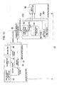
- Fig. 13 is a diagram which illustrates a biometric authentication apparatus according to a sixth embodiment.
- the configuration illustrated in Fig. 13 will be described for exemplary purpose only, and the present art is not restricted to such a configuration.
- the same components illustrated in Fig. 13 as those in Fig. 1 or Fig. 12 are denoted by the same reference numerals.
- the program storage unit 202 is an example of a storage which stores programs, and is configured as a computer-readable/writable storage medium.
- the program storage unit 202 stores an OS 218, application programs 220, etc.
- Examples of the application programs 220 include aforementioned imaging program, authentication program, etc.
- the present art provides the following advantages.
Abstract
Description
- A certain aspect of the embodiments discussed herein is related to an authentication apparatus.
- Biometric authentication is a technique which provides user identity verification using biometric features such as fingerprints, the face, the iris, voiceprints, handwriting, etc. As compared with user identity verification based upon the user's memory such as a secret identification code, password, etc., in principle, it is difficult to crack biometric authentication by spoofing (i.e., an unauthorized user using a false identity). Accordingly, there has been more interest in biometric authentication as a technique which provides high security.
- The multi-biometric technique is a technique which uses a combination of multiple biometric authentication items such as fingerprint authentication and face authentication, etc. By adjusting the combination, the ease of use may be improved or the security level may be raised. With an arrangement in which the user identity is verified if at least one of multiple authentication items is successful, authentication may be performed using a different authentication item even if fingerprint authentication may not be performed due to a situation in which the user's finger has been injured, etc., thereby improving the ease of use. An arrangement in which the user identity is verified only if all the multiple authentication items are successful provides an extremely high security level. Thus, such an arrangement may be applied to an access control operation for highly classified information, and so forth.
- The user's hand is highly suitable for acquiring biometric information. Various authentication methods such as fingerprint authentication, vein authentication, hand outline authentication, etc., have already been implemented. Using a combination of such authentication methods, multi-biometric authentication is easily realized, which has the potential to improve authentication convenience or improve authentication precision.
- Japanese Laid-open Patent Publication No.
2006-65400 2006-285487 2004-139611 2003-75892 2002-71578 2006-153633 - Accordingly, it is an object of the present invention to provide an authentication apparatus for performing different types of authentication.
- According to an aspect of an embodiment, an apparatus for authenticating a user includes a detector for determining a state or a position of a bodily part placed by the user for biometric authentication, a unit capable of obtaining biometric data from different portion of the bodily part, a plurality of biometric authentication engines capable of authenticating the user by using one of a plurality of authentication algorisms by comparing the biometric data with reference data, respectively, and a controller for selecting one of the different portions of the bodily part so as to select associated biometric data, and determining one of the biometric authentication engines for authenticating the user on the basis of the state or the position of the bodily part placed.
-
-
Fig. 1 is a diagram which illustrates a biometric authentication apparatus according to a first embodiment; -
Fig. 2 is a flowchart which illustrates a processing procedure for authentication; -
Figs. 3A and 3B are diagrams which illustrate an example of an imaging apparatus; -
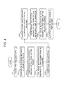
Fig. 4 is a flowchart which illustrates a processing procedure for imaging processing and authentication processing; -
Fig. 5 is a diagram which illustrates a modification of the imaging apparatus; -
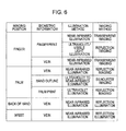
Fig. 6 is a diagram which illustrates biometric information, illumination, and an imaging method that corresponds to the imaging position; -
Figs. 7A and 7B are diagrams which illustrate an imaging apparatus according to a third embodiment; -
Figs. 8A and 8B are diagrams which illustrate an example of the imaging apparatus; -
Fig. 9 is a diagram which illustrates an imaging apparatus according to a fourth embodiment; -
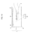
Fig. 10 is a diagram which illustrates another imaging apparatus; -
Fig. 11 is a diagram which illustrates yet another imaging apparatus; -
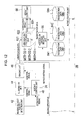
Fig. 12 is diagram which illustrates a biometric authentication apparatus according to a fifth embodiment; -
Fig. 13 is a diagram which illustrates a biometric authentication apparatus according to a sixth embodiment; and -
Fig. 14 is a diagram which illustrates a hardware configuration of a biometric authentication apparatus according to a seventh embodiment. - Preferred embodiments of the present art will be described with reference to the accompanying drawings.
- Description will be made regarding a first embodiment with reference to
Fig. 1 andFig. 2 .Fig. 1 is a diagram which illustrates a biometric authentication apparatus according to the first embodiment.Fig. 2 is a flowchart which illustrates a processing procedure for authentication. The configurations illustrated inFig. 1 andFig. 2 will be described for exemplary purpose only. The present art is not restricted to such configurations. - A
biometric authentication apparatus 2A is an example of an imaging apparatus according to the present art or an authentication apparatus employing the imaging apparatus. With such an arrangement, the imaging position is determined based upon the position of the user's hand, which is an example of the imaging target body, the optimum imaging method is selected according to the position thus determined, and the imaging is performed using the imaging method thus selected. - As illustrated in
Fig. 1 , thebiometric authentication apparatus 2A includes animaging apparatus 4 and anauthentication unit 6. Theimaging apparatus 4 selects an imaging method according to the position of the user's hand, which is an imaging subject, and which acquires an image using the imaging method thus selected. Theauthentication unit 6 performs authentication using the biometric image thus acquired. For example, theauthentication unit 6 verifies the biometric image acquired in the imaging operation against a registered image, and outputs an authentication output, which is an authentication result. - The
imaging apparatus 4 includes an imaging subjectposition detection unit 42, anillumination unit 44, animaging unit 46, and animaging control unit 48. The imaging subjectposition detection unit 42 detects the position of the imaging subject. The imaging subjectposition detection unit 42 detects the position of the user's hand, which is an example of the imaging subject. The imaging subjectposition detection unit 42 includes a first insertion detection unit 422 (first detector) and a second insertion detection unit 424 (second detector) which is arranged at a position that differs from that of the first insertion detection unit 422 (Figs. 3A and 3B ). The detection results thus detected at these positions are transmitted to theimaging control unit 48, and are used as reference data based upon which the imaging method is selected. A detector determines a state or position of a bodily part placed by a user for biometric authentication. Theimaging unit 46 is a unit capable of obtaining biometric data from different portion of the bodily part. - The
illumination unit 44 is an illumination device which emits light, necessary for the imaging, to the imaging subject. Theillumination unit 44 performs an illumination operation according to the imaging method selected by theimaging control unit 48. - The
imaging unit 46 acquires an image of the imaging subject. Theimaging unit 46 acquires an image of a position on/in the imaging subject using the optimum imaging method selected by theimaging control unit 48. Theimaging unit 46 may be configured as a CCD (Charge Coupled Device) camera, for example. - The
imaging control unit 48 controls theillumination unit 44 and theimaging unit 46. Upon receiving a detection signal which indicates the position of the imaging subject from the imaging subjectposition detection unit 42, theimaging control unit 48 determines the imaging position based upon the position thus detected, and selects the optimum illumination and/or the optimum imaging method. - Furthermore, the
authentication unit 6 includes averification processing unit 62, a registration data database (DB) 64, and aresult output unit 66. Theverification processing unit 62 verifies the biometric image acquired by theimaging unit 46, i.e., the verification data, against the registration data registered in theregistration data DB 64. Theverification processing unit 62 outputs a verification result which indicates a match/mismatch judgment or a similarity level. Theverification processing unit 62 has a plurality of biometric authentication engines capable of authenticating the user by using one of a plurality of authentication algorisms by comparing the biometric data with reference data, respectively. Theimaging control unit 48 is a controller for selecting one of the different portions of the bodily part so as to select associated biometric data, and determining one of the biometric authentication engines for authenticating the user on the basis of the state or position of the bodily part placed. - The
registration data DB 64 stores biometric information, which is used to verify the verification data, as registration data. The verification result obtained by theverification processing unit 62 is outputted via theresult output unit 66 as the authentication output. - The processing procedure (
Fig. 2 ) for the authentication processing performed by thebiometric authentication apparatus 2A having such a configuration includes imaging processing and authentication processing. The processing procedure is an example of an imaging method or an imaging program. As illustrated inFig. 2 , in the processing procedure, the imaging subjectposition detection unit 42 detects the position of the imaging subject, and transmits the result thus detected to the imaging control unit 48 (Step S1). Theimaging control unit 48 acquires the position information, determines the position based upon the detection position, selects the optimum imaging method, and transmits a control signal, which is an instruction to provide the imaging method thus selected, to theillumination unit 44 and the imaging unit 46 (Step S2). The image acquired using the imaging method thus selected is transmitted to theverification processing unit 62 as the verification data (Step S3). Theverification processing unit 62 reads out the registration data from theregistration data DB 64 in which the registration data was registered beforehand, makes a comparison between the verification data and the registration data, and outputs the verification result to the result output unit 66 (Step S4). Then, the imaging processing and the authentication processing end. - Next, description will be made regarding the
imaging apparatus 4 with reference toFigs. 3A, 3B andFig. 4 .Figs. 3A and 3B are diagrams illustrating an example configuration of the imaging apparatus.Fig. 4 is a flowchart which illustrates the processing procedure for the imaging processing and the authentication processing. The configurations illustrated inFigs. 3A, 3B andFig. 4 are described for exemplary purpose only, and the present art is not restricted to such configurations. The same components illustrated inFigs. 3A and 3B as those inFig. 1 are denoted by the same reference numerals. - The
imaging apparatus 4 has a configuration which provides two different imaging methods, i.e., a transparent imaging (image acquisition) method and a reflection imaging (image acquisition) method. As illustrated inFig. 3A and Fig. 3B , theimaging apparatus 4 includes acasing 10 which allows the user to insert his/herhand 8 as the imaging subject. Thecasing 10 includes a firstinsertion detection unit 422 and a secondinsertion detection unit 424 each of which detects the position of the user'shand 8 thus inserted, i.e., a user'sfinger 82, and which are arranged along the insertion direction in which the user's hand is to be inserted. Each of theinsertion detection units light emitting unit 14 is arranged at aceiling portion 12 of thecasing 10, and alight receiving unit 18 is arranged at abase portion 16 thereof. With such an arrangement, the light L which is to reach thelight receiving unit 18 from thelight emitting unit 14 is interrupted by the user'sfinger 82 or thepalm 84 of the user's hand, thereby allowing the position of the user'shand 8 to be detected based upon the output from thelight receiving unit 18. - As illustrated in
Fig. 3A , a near-infrared illumination device 442 included in theillumination unit 44 is arranged at theceiling portion 12 of thecasing 10. Theimaging unit 46 is arranged below thebase portion 16 of thecasing 10. Theimaging unit 46 acquires an image by receiving the light that passes through the user'shand 8 using theillumination 20 provided by the near-infrared illumination device 442. In this case, a transparent imaging method is used as the imaging method. - Furthermore, as illustrated in
Fig. 3B , a near-infrared illumination device 444 included in theillumination unit 44 is arranged at thebase portion 16 of thecasing 10. With such an arrangement, using theillumination 22 provided by the near-infrared illumination device 444 arranged at thebase portion 16 of thecasing 10, theimaging unit 46 receives the reflected light from the user'shand 8, and acquires an image thereof. In this case, a reflection imaging method is used as the imaging method. - Such an arrangement allows multiple biometric information (transparent image and reflection image) to be easily acquired with respect to multiple different positions on/in a single subject using a
single imaging apparatus 4. - The processing procedure for the imaging processing and the authentication processing performed by the
biometric authentication apparatus 2 is an example of an imaging method, an authentication method, an imaging program, or an authentication program. With such an arrangement, when the subject inserts his/herhand 8 into thecasing 10, multiple images of different positions on/in the subject are acquired, thereby enabling authentication to be performed based upon the multiple biometric images. - In the processing procedure, when the
finger 82 reaches the position (first stage) where thefinger 82 interrupts the light L1 after the subject inserts his/herhand 8 partway into thecasing 10 as illustrated inFig. 4 , theinsertion detection unit 422 detects the insertion (Step S11), detects that thefinger 82 has entered the imaging range (field of view) of theimaging unit 46, and transmits a corresponding detection signal to theimaging control unit 48. - Upon receiving the detection signal, the
imaging control unit 48 turns on the near-infrared illumination device 442 arranged on the back of thehand 8 side (Step S12) so as to generate theillumination 20, thereby providing back illumination of thehand 8. Furthermore, theimaging control unit 48 performs transparent imaging of the veins of the finger (or fingerprints) (Step S13). Thus, the image information with respect to the finger veins (or fingerprints) is acquired (Step S14). - When the finger reaches the position where the
finger 82 interrupts the light L2 after the subject further inserts his/her hand 8 (second stage) as illustrated inFig. 3B , theinsertion detection unit 424 detects the insertion (Step S15), detects that thepalm 84 has entered the imaging range (field of view) of theimaging unit 46, and transmits a corresponding detection signal to theimaging control unit 48 as a notice. Theimaging control unit 48 turns on the near-infrared illumination device 444 on thepalm 84 side (Step S16), and performs reflection imaging of the veins of the palm using the illumination 22 (Step S17). Thus, image information with respect to the veins of the palm is acquired (Step S18). Authentication processing is performed based upon the images thus acquired (Step S19). - Immediately after the imaging processing, the images thus acquired in the first stage and the second stage are outputted to the
verification processing unit 62, and verification is performed. Also, an arrangement may be made in which judgment is made whether the verification image has been acquired for the finger or the palm (such a notice may be transmitted by storing the position information in a data header according to the biometric data format stipulated by ISO/IEC19794-9 or the like), and a notice is transmitted from theimaging control unit 48 to theverification processing unit 62 via a signal line (brokenline 24 inFig. 1 ). - Description has been made regarding an arrangement in which the position detection is performed using the
insertion detection units imaging unit 46 provides functions as theinsertion detection units imaging unit 46, which is an imaging camera, for example, and the position in the image thus acquired in the field of view is determined. - Description has been made with reference to
Fig. 3A and Fig. 3B regarding an arrangement in which thecasing 10 is arranged horizontally. Also, as illustrated inFig. 5 , an arrangement may be made in which thecasing 10 is arranged such that it stands vertically, thereby allowing the user to insert his/her hand along the vertical direction indicated by the arrow a. The same components illustrated inFig. 5 as those inFig. 3A and Fig. 3B are denoted by the same reference numerals, and description thereof will be omitted. - Features, advantages, and modifications drawn from the above-described embodiment will be listed below.
- The
imaging apparatus 4 is an apparatus which performs imaging processing so as to obtain biometric information, and includes theimaging unit 46 which performs imaging processing so as to obtain biometric information, and theillumination unit 44. Theimaging apparatus 4 has a detection function for detecting the relative position of the imaging subject with respect to theimaging unit 46, and is capable of selecting the imaging method according to the relative position of the imaging subject thus detected. - The
biometric authentication apparatus 2A includes theimaging apparatus 4 which performs imaging processing so as to obtain biometric information. Theimaging apparatus 4 includes theimaging unit 46 which performs imaging processing so as to obtain biometric information, and theillumination unit 44. Theimaging apparatus 4 has a detection function for detecting the relative position of the subject with respect to theimaging unit 46, and a function for selecting the imaging method according to the relative position of the imaging subject. Theimaging apparatus 4 further includes theauthentication unit 6 which performs authentication based upon the image acquired using the imaging method (imaging mode) thus selected, thereby allowing the authentication to be performed according to the imaging method thus selected based upon the position of the imaging subject. - The
imaging apparatus 4 or thebiometric authentication apparatus 2A is an apparatus which acquires biometric information with respect to thehand 8. When the subject inserts his/herhand 8 into thecasing 10, the insertion stage is detected so as to switch the imaging method, and biometric information is acquired. Thus, such an arrangement is capable of acquiring the most suitable biometric information according to the position thus detected, thereby providing authentication using such a biometric image thus acquired. - The
imaging apparatus 4 or thebiometric authentication apparatus 2A is an apparatus which acquires images so as to obtain biometric information with respect to thehand 8, and which has a function for detecting the position relation between the illumination and the imaging subject, thereby obtaining biometric information based upon the image according to the position. Such an arrangement provides high-precision authentication. - As described above, such a simple arrangement is capable of acquiring images so as to obtain multiple kinds of biometric information using an optimum method. Thus, such an arrangement provides high-precision authentication and improves the degree of freedom of the authentication.
- The optimum imaging method is selected according to the position of the target body, and an image of the target body may be acquired using the imaging method thus selected.
- In a case in which the position of the target body may change, the optimum imaging method is selected according to the position so as to acquire an image of the target body. Thus, multiple images may be acquired with respect to a single target body at different positions.
- Authentication may be performed based upon biometric images acquired using imaging methods which are selected according to the position of the biometric target, thereby improving the authentication precision.
- Next, description will be made regarding a second embodiment with reference to
Fig. 6. Fig. 6 is a diagram which illustrates an example of a selection operation in the imaging method. The arrangement illustrated inFig. 6 will be described for exemplary purpose only, and the present art is not restricted to such an arrangement. - Description has been made in the first embodiment regarding an arrangement in which an image of the veins of the finger (or fingerprints) is acquired in the first stage, and an image of the veins of the palm is acquired in the second stage. However, the biometric information with respect to the hand is not restricted to such information. Rather, various kinds of information may be used, and an optimum imaging method may be selected. Various combinations of the imaging position, biometric information, illumination method, and imaging method may be used as illustrated in
Fig. 6 . A combination may be selected from among these combinations as desired. - Referring to
Fig. 6 , in a case in which the imaging position is the finger, fingerprint data or vein data may be acquired as biometric information. In a case in which fingerprint data is used, a near-infrared illumination method is selected so as to provide illumination. In this case, the transparent imaging method is used as the imaging method. Alternatively, an ultraviolet illumination method or a visible light illumination method is selected so as to generate the illumination. In this case, reflection imaging is selected as the imaging method. As described above, in a case in which finger vein information is obtained as biometric information, the transparent imaging method using infrared illumination is selected. - In a case in which the palm of the hand is the imaging position, palm vein data, hand outline data, or palm print data is obtained. In this case, an infrared illumination method or an ultraviolet illumination method is selected so as to provide the illumination. Furthermore, a reflection imaging method or a silhouette imaging method is selected as the imaging method. Moreover, the back of the hand and the wrist may be used as the imaging position. In both cases, vein information is acquired as biometric information. In this case, the infrared illumination method is employed so as to generate the illumination, and the reflection imaging method is selected as the imaging method.
- As described above, there is a need to appropriately select or switch the illumination method or the imaging method according to the biometric image to be used for the authentication method. With the
biometric authentication apparatus 2A, various kinds of biometric information may be acquired with respect to multiple different positions based upon the multiple detected positions. In the drawings, silhouette imaging may be performed using the imaging mode for transparent imaging illustrated inFig. 3A . - Next, description will be made regarding a third embodiment with reference to
Figs. 7A and 7B andFigs. 8A and 8B .Figs. 7A and 7B andFigs. 8A and 8B are diagrams which illustrate an imaging apparatus according to the third embodiment. The configuration illustrated inFigs. 7A and 7B andFigs. 8A and 8B will be described for exemplary purpose only, and the present art is not restricted to such a configuration. The same components illustrated inFigs. 7A and 7B andFigs. 8A and 8B as those inFig. 1 andFigs. 3A and 3B are denoted by the same reference numerals. - As illustrated in
Fig. 7A and Fig. 7B , theimaging apparatus 4 has a configuration in which theimaging unit 46 is arranged within thecasing 10, which allows an image of the user'shand 8 which is an imaging subject to be acquired via awindow portion 26 formed on theceiling portion 12 side of thecasing 10. Acontact detection device 28, which is a means for detecting whether thefinger 82 is in contact, is arranged at the edge of thewindow portion 26 of thecasing 10. Thecontact detection device 28 detects whether or not thefinger 82 is in contact, and input a corresponding detection signal to theimaging control unit 48 so as to select the imaging method. - As illustrated in
Fig. 7A and Fig. 7B , when thefinger 82 is in contact with thecontact detection device 28, a transparent imaging method is selected. In this case, a near-infrared illumination device 446 arranged obliquely above thehand 8 is turned on, thereby allowing theimaging unit 46 to acquire a transparent image of thefinger 82. - Furthermore, as illustrated in
Fig. 8A and Fig. 8B , when there is a distance between thefinger 8 and thecontact detection device 28, i.e., when thefinger 8 is not in contact with thecontact detection device 28, the reflection imaging method is selected. In this case, a near-infrared illumination device 448 arranged obliquely below thehand 8 is turned on, thereby allowing theimaging unit 46 to acquire a reflection image of thepalm 48. With such an arrangement, a single device may serve as the near-infrared illumination devices - With such an arrangement, the detection of the position of the imaging subject may be performed using a detector such as a distance sensor or the like, instead of the contact detection device.
- Description has been made in the first embodiment regarding an arrangement in which the
insertion detection units position detection unit 42 which detects the position of thefinger 82. Also, an arrangement may be made in which a distance sensor is arranged so as to detect the distance to the imaging subject. Also, an arrangement may be made in which a contact sensor is arranged so as to detect whether or not the imaging subject is in contact. Also, such an arrangement may allow the subject to select the imaging method or the biometric information to be supplied, based upon the information of whether or not the imaging subject is in contact. Also, an arrangement may be made in which the biometric information is selected according to the authentication method. In a case in which an image acquired by an imaging camera which is an imaging means or a proximity detection function provided by a distance sensor or the like is used, an arrangement may be made in which, when the imaging subject enters the field of view, an illumination is turned on so as to acquire the biometric information. - Next, description will be made regarding a fourth embodiment with reference to
Fig. 9 ,Fig. 10 , andFig. 11 .Fig. 9 ,Fig. 10 , andFig. 11 are diagrams which illustrate an imaging apparatus according to the fourth embodiment. The configuration illustrated inFig. 9 ,Fig. 10 , andFig. 11 will be described for exemplary purpose only, and the present art is not restricted to such a configuration. - In a case in which a silhouette image is acquired using the
imaging apparatus 4, the configuration described in the first embodiment (Fig. 3A ) may be employed. With such an arrangement, as illustrated inFig. 9 , the near-infrared illumination device 442 may have a function for providing illumination with a low magnitude. - In this case, the
illumination 23 is provided as a background illumination with a low magnitude, instead of emitting light to thefinger 82 which is an imaging subject facing theimaging unit 46. With such an arrangement which has a function for providing a background illumination with a reduced magnitude, the outline data is protected from being degraded due to saturation of the imaging element included in theimaging unit 46. The same components illustrated inFig. 9 as those inFig. 3A are denoted by the same reference numerals, and description thereof will be omitted. - Also, an arrangement may be made in which the aperture or the exposure condition of the
imaging unit 46 is adjusted, instead of employing a method for providing the illumination with a reduced magnitude. It may be noted that a plane illumination device, which emits light with a uniform magnitude from the background surface, is most preferably employed. However, in a case in which the difference in the luminance between the imaging subject surface and the background is sufficiently great, a silhouette image may be obtained by performing image binarization processing. Such an arrangement may be applied regardless of whether or not the illumination device is a plane illumination device. - As another arrangement, as illustrated in
Fig. 10 , an arrangement may be made in which abackground illumination device 45 is arranged at theceiling portion 12 of thecasing 10, and abackground illumination 30 is provided on the back side of thehand 8 which is an imaging subject. The same components illustrated inFig. 10 as those inFig. 3A are denoted by the same reference numerals, and description thereof will be omitted. With such an arrangement, the illumination is supplied to the background surface, whereby the background surface reflects light with a uniform luminance. In this case, an arrangement is most preferably made in which the illumination is supplied such that the background surface is illuminated with a uniform luminance. However, it is sufficient that there is a sufficiently great difference in the luminance between the background and the imaging subject - Also, as yet another arrangement, as illustrated in
Fig. 11 , an arrangement may be made in which ablack background plate 47 is arranged at theceiling portion 12 of thecasing 10 as a background means which absorbs the light, thereby providing the back side of thehand 8, which is an imaging subject, as the black side. The same components illustrated inFig. 11 as those inFig. 3B are denoted by the same reference numerals, and description thereof will be omitted. - With such an arrangement, the imaging subject is setted to the light (white) state, and the background is setted to the dark (black) state. The background is formed in a color which absorbs the illumination wavelength (generally, black is preferably employed), and the
illumination 22 is supplied from the front side of the imaging subject (from the side facing the imaging unit 46). With such an arrangement, the contrast of the silhouette image of thehand 8 is improved, thereby providing a clear silhouette image. - Next, description will be made regarding a fifth embodiment with reference to
Fig. 12. Fig. 12 is a diagram which illustrates a biometric authentication apparatus according to the fifth embodiment. The configuration illustrated inFig. 12 will be described for exemplary purpose only, and the present art is not restricted to such a configuration. The same components illustrated inFig. 12 as those inFig. 1 are denoted by the same reference numerals. - A
biometric authentication apparatus 2B has a configuration in which the verification method used by theauthentication unit 6 is selected according to the imaging method selected by theimaging unit 46. With such an arrangement, theauthentication unit 6 includes:multiple verification units 611, 622, ..., 62n, which correspond the respective imaging methods; a verificationmethod selection unit 68 receives a method notice signal which is the imaging method notice information transmitted from theimaging control unit 48 and which selects the verification method; andregistration data DBs - With such an arrangement, the verification
method selection unit 68 selects one verification processing unit from among theverification processing units 621 through 62n according to the imaging method. Furthermore, theimaging unit 46 supplies the verification data to the verification processing unit selected from among theverification processing units 621 through 62n. Moreover, one registration data DB is selected from among theregistration data DBs 641 through 64n according to the selection of the verification method selected by the verificationmethod selection unit 68, thereby selecting the registration data as the authentication information that corresponds to the verification data. Verification is performed according to the imaging method, and theresult output unit 66 outputs the verification results obtained by theverification processing units 621 through 62n. - With the embodiment, the authentication information and/or the authentication method, which are to be used to perform the authentication, are selected according to the imaging method selected based upon the position of the biometric target. This improves the degree of freedom of the selection of the authentication information, and improves the authentication precision.
- Furthermore, the authentication information and/or the authentication method, which are used to perform the authentication, are selected according to the imaging method selected based upon the position of the biometric target. Thus, multiple biometric information obtained according to the respective positions may be used. Furthermore, the authentication information and/or the authentication method that correspond to the biometric information can be selected. Thus, multiple authentication can be performed at once. Furthermore, the authentication can be performed based upon the authentication information selected according to the selection of the position of the biometric target.
- Next, description will be made regarding a sixth embodiment with reference to
Fig. 13. Fig. 13 is a diagram which illustrates a biometric authentication apparatus according to a sixth embodiment. The configuration illustrated inFig. 13 will be described for exemplary purpose only, and the present art is not restricted to such a configuration. The same components illustrated inFig. 13 as those inFig. 1 orFig. 12 are denoted by the same reference numerals. - A
biometric authentication apparatus 2C has a configuration in which the authentication method used by theauthentication unit 6 is selected according to the imaging method selected by theimaging unit 46, in the same way as in the fifth embodiment. With such an arrangement, theauthentication unit 6 includesmultiple verification units verification units verification processing unit 62 and aregistration data DB 64. - As a means which selects one verification unit from among the
verification units imaging unit 46, the verificationmethod selection unit 68 is arranged upstream to theverification units imaging unit 48, the verificationmethod selection unit 68 selects one verification unit that corresponds to the verification method for the verification data that corresponds to the imaging method, from among theverification units - With such an arrangement, the verification
method selection unit 68 selects one verification unit from among theverification units imaging unit 46 supplies the verification data to theverification processing unit 62 included in the verification unit selected from among theverification units registration DB 64 included in the verification unit selected from among theverification units result output unit 66 outputs the verification results obtained by theverification units - With the present embodiment, the same advantages can be obtained as those obtained in the fifth embodiment.
- Next, description will be made regarding a seventh embodiment with reference to
Fig. 14. Fig. 14 is a diagram which illustrates a hardware configuration of a biometric authentication apparatus according to the seventh embodiment. The configuration illustrated inFig. 14 will be described for exemplary purpose only, and the present art is not restricted to such a configuration. The same components inFig. 14 as those inFig. 1 are denoted by the same reference numerals. - A
biometric authentication apparatus 2 is an example of the hardware configuration for providing the configuration of the above-describedbiometric authentication apparatuses 2A (Fig. 1 ) or 2B (Fig. 12 ), or thebiometric authentication apparatus 2C (Fig. 13 ). Thebiometric authentication apparatus 2 has a configuration including a computer for providing theimaging apparatus 4 and/or theauthentication unit 6. Thebiometric authentication apparatus 2 further includes aprocessor 200, aprogram storage unit 202, adata storage unit 204, RAM (Random-Access Memory) 206, anoperation input unit 208, aposition detection unit 210, anillumination unit 212, acamera 214, and adisplay unit 216, which are connected to each other via abus 217. - The
processor 200 executes an imaging control operation, an illumination control operation, verification processing, a display control operation, etc. For example, theprocessor 200 is configured as a CPU (Central Processing Unit), and performs an illumination operation, an imaging operation, acquisition of biometric information, verification against registration data, output of authentication results, etc., by executing an OS (Operating System) and application programs such as an imaging program, an authentication program, etc. The above-described imaging control unit 48 (Fig. 1 ), the verification processing unit 62 (Fig. 1 ), the result output unit 66 (Fig. 1 ,Fig. 12 orFig. 13 ), theverification processing units Fig. 12 ), the verification method selection unit 68 (Fig. 12 ,Fig. 13 ), theverification units Fig. 13 ), and so forth, are configured as a combination of theprocessor 200 and theRAM 206. - The
program storage unit 202 is an example of a storage which stores programs, and is configured as a computer-readable/writable storage medium. Theprogram storage unit 202 stores anOS 218,application programs 220, etc. Examples of theapplication programs 220 include aforementioned imaging program, authentication program, etc. - The
data storage unit 204 is an example of a storage means which stores data, and is configured as a recording medium. In thedata storage unit 204, a registrationdata storage unit 222, a verificationdata storage unit 224, a selectiondata storage unit 226, etc., are provided. In the registrationdata storage unit 222, registration data, which is biometric information to be used to verify the verification data, is registered. The registrationdata storage unit 222 provides the aforementioned registration data DB 64 (Fig. 1 andFig. 13 ), orregistration data DBs Fig. 12 ). The verificationdata storage unit 224 stores the verification data acquired by theauthentication unit 6 via theimaging unit 46. Furthermore, the selectiondata storage unit 226 stores selection data such as the verification methods that correspond to the respective imaging methods, the aforementioned illumination methods that correspond to the respective imaging method, etc. - The RAM provides a work area. The
operation input unit 208 is used to input information etc. A keyboard or the like is used to input information. - The
position detection unit 210 detects the position of the imaging subject with respect to the imaging range of thecamera 214, and is configured as the first andsecond photo interrupters photo interrupters - The
illumination unit 212 illuminates the imaging position of the imaging subject (body). For example, theillumination unit 212 is configured as near-infrared light sources - The
camera 214 is an example of the imaging unit, and is configured as a CCD, for example. Thecamera 214 corresponds to the imaging unit 46 (Fig. 1 ,Fig. 12 , andFig. 13 ). In this case, thecamera 212 may include an exposure control component such as an aperture or the like, or a component which controls the light sensitivity, which can be adjusted or controlled according to the imaging method. - The
display unit 216 displays a biometric image, authentication results, etc., and is configured as an LCD (Liquid Crystal Display), for example. - Such an arrangement provides the function units or apparatuses according to the first through sixth embodiments, thereby providing high-precision image acquisition and authentication.
- In the above-described embodiments, the illumination unit may be configured as a visible light source or an ultraviolet light source, or may be configured as a single light source or multiple light sources, depending upon the imaging method. Also, in some cases, the
illumination unit 212 may be configured as a point light source. - Description has been made in the above-described embodiment regarding an arrangement in which the
imaging apparatus 4 and theauthentication unit 6 are configured as a single device. Also, an arrangement may be made in which these components may be configured as separate devices independent of one another. - Description has been made in the above-described embodiment regarding an arrangement in which the selection of the registration data or the verification method is performed as the selection of the authentication information and/or the authentication method according to the selection of the imaging method or the biometric information. However, the registration data and/or the illumination method are not restricted to the above-described arrangements.
- Next, the technical sprits drawn from the above-described embodiments of the present art will be listed as the appendixes according to the description format of the claims. The technical scopes according to the present art can be understood by various levels or variations thereof over the range from the upper concept up to the lower concept. The present art is not restricted to the following appendixes.
- As described above, description has been made regarding the most preferable embodiment according to the present art. However, the present art is not restricted to the above description. It is needless to say that various modifications and changes can be made by those skilled in this art based upon the spirit of the present art disclosed in claims or in the best mode of the present art. Also, it is needless to say that such modifications and changes are encompassed in the technical scope of the present art.
- The present art provides the following advantages.
- Such an arrangement allows an image of a target body to be acquired using an optimum imaging method selected according to the position of the target body.
- In a case in which the position of the target body can change, such an arrangement allows the images of the target body to be acquired using the respective optimum imaging methods selected according to the positions thereof, thereby providing multiple images acquired at different positions with respect to the single target body.
- Such an arrangement is capable of performing authentication using a biometric image acquired using the imaging method selected according to the position of the biometric target, thereby improving the authentication precision.
- Such an arrangement selects the authentication information and/or the authentication method to be used to perform authentication, according to the imaging method selected based upon the position of the biometric position, thereby improving the degree of freedom of the selection of the authentication information, and thereby improving the authentication precision.
- Such an arrangement selects the authentication information and/or the authentication method to be used to perform authentication, according to the imaging method selected based upon the position of the biometric target, thereby allowing multiple biometric information obtained according to the respective positions to be used. Furthermore, such an arrangement allows the authentication information and/or the authentication method to be selected according to the biometric information. Thus, multiple authentication can be performed at once. Furthermore, the authentication can be performed based upon the authentication information selected according to selection of the position of the biometric target.
- The other purposes, features, and advantages of the present art can be more clearly understood with reference to the accompanying drawings and embodiments.
- With the present art, the authentication information and/or the authentication method used to perform authentication are selected according to the imaging method selected according to the position of the biometric target which is an example of the imaging subject, thereby allowing multiple biometric information obtained according to the respective positions to be used. Furthermore, such an arrangement allows the authentication information and/or the authentication method to be selected according to the biometric information. Thus, multiple authentication can be performed at once. Furthermore, the authentication can be performed based upon the authentication information selected according to the selection of the position of the biometric target. Thus, such an arrangement can be widely applied to image acquisition of the imaging subject, biometric authentication, and so forth, thereby providing a useful technique.
- As mentioned above, the present invention has been specifically described for better understanding of the embodiments thereof and the above description does not limit other aspects of the invention. Therefore, the present invention can be altered and modified in a variety of ways without departing from the gist and scope thereof.
- All examples and conditional language recited herein are intended for pedagogical purposes to aid the reader in understanding the invention and the concepts contributed by the inventor to furthering the art, and are to be construed as being without limitation to such specifically recited examples and conditions, nor does the organization of such examples in the specification relate to a showing of the superiority and inferiority of the invention. Although the embodiments of the present inventions have been described in detail, it should be understood that the various changes, substitutions, and alterations could be made hereto without departing from the spirit and scope of the invention.
Claims (15)
- An apparatus for authenticating a user comprising:a detector for determining a state or position of a bodily part placed by the user for biometric authentication;a unit capable of obtaining biometric data from different portions of the bodily part;a plurality of biometric authentication engines capable of authenticating the user by using one of a plurality of authentication algorisms by comparing the biometric data with reference data, respectively; anda controller for selecting one of the different portions of the bodily part so as to select associated biometric data, and determining one of the biometric authentication engines for authenticating the user on the basis of the state or position of the bodily part placed.
- The apparatus of claim 1, wherein the detector includes a first detector for determining the state or the position of a bodily part placed by the user for biometric authentication and a second detector for determining the state or the position of a bodily part placed by the user for biometric authentication, the second detector being arranged at a position that differs from that of the first detector.
- The apparatus of claim 2, wherein the controller determines one of the biometric authentication engines on the basis of a detecting result of the first detector and a detecting result of the second detector.
- The apparatus of claim 1, further comprising a casing for accommodating the bodily part.
- The apparatus of claim 4, wherein the controller selects one of the different portions of the bodily part in accordance with a degree of a insertion of the bodily part.
- A method of controlling an apparatus for authenticating a user comprising:determining a state or position of a bodily part placed by the user for biometric authentication;obtaining biometric data from different portion of the bodily part;selecting one of the different portions of the bodily part so as to select associated biometric data; anddetermining one of a plurality of biometric authentication engines capable of authenticating the user by using one of a plurality of authentication algorisms by comparing the biometric data with reference data, respectively, for authenticating the user on the basis of the state or position of the bodily part placed.
- The method of claim 6, wherein the apparatus further comprises a first detector for determining the state or the position of a bodily part placed by the user for biometric authentication and a second detector for determining the state or the position of a bodily part placed by the user for biometric authentication, the second detector being arranged at a position that differs from that of the first detector.
- The method of claim 7, wherein the determining determines one of the biometric authentication engines on the basis of a detecting result of the first detector and a detecting result of the second detector.
- The method of claim 6, wherein the apparatus further comprises a casing for accommodating the bodily part.
- The method of claim 9, wherein selecting selects one of the different portions of the bodily part in accordance with a degree of a insertion of the bodily part.
- A computer-readable recording medium that stores a computer program for authenticating a user, by controlling an apparatus according to a process comprising:determining a state or s position of a bodily part placed by the user for biometric authentication;obtaining biometric data from different portion of the bodily part;selecting one of the different portions of the bodily part so as to select associated biometric data; anddetermining one of a plurality of biometric authentication engines capable of authenticating the user by using one of a plurality of authentication algorisms by comparing the biometric data with reference data, respectively, for authenticating the user on the basis of the state or the position of the bodily part placed.
- The computer-readable recording medium of claim 11, wherein the apparatus further comprises a first detector for determining the state or the position of a bodily part placed by the user for biometric authentication and a second detector for determining the state or the position of a bodily part placed by the user for biometric authentication, the second detector being arranged at a position that differs from that of the first detector.
- The computer-readable recording medium of claim 12, wherein the determining determines one of the biometric authentication engines on the basis of a detecting result of the first detector and a detecting result of the second detector.
- The computer-readable recording medium of claim 11, wherein the apparatus further comprises a casing for accommodating the bodily part.
- The computer-readable recording medium of claim 14, wherein selecting selects one of the different portions of the bodily part in accordance with a degree of an insertion of the bodily part.
Applications Claiming Priority (1)
| Application Number | Priority Date | Filing Date | Title |
|---|---|---|---|
| JP2008258951A JP5521304B2 (en) | 2008-10-03 | 2008-10-03 | Imaging apparatus, imaging program, imaging method, authentication apparatus, authentication program, and authentication method |
Publications (2)
| Publication Number | Publication Date |
|---|---|
| EP2172911A2 true EP2172911A2 (en) | 2010-04-07 |
| EP2172911A3 EP2172911A3 (en) | 2012-07-11 |
Family
ID=41395571
Family Applications (1)
| Application Number | Title | Priority Date | Filing Date |
|---|---|---|---|
| EP09171824A Withdrawn EP2172911A3 (en) | 2008-10-03 | 2009-09-30 | Authentication apparatus |
Country Status (4)
| Country | Link |
|---|---|
| US (1) | US8816817B2 (en) |
| EP (1) | EP2172911A3 (en) |
| JP (1) | JP5521304B2 (en) |
| KR (1) | KR101120932B1 (en) |
Cited By (4)
| Publication number | Priority date | Publication date | Assignee | Title |
|---|---|---|---|---|
| WO2012041826A1 (en) * | 2010-09-28 | 2012-04-05 | Icognize Gmbh | Method and device for the non-contact detection of biometric features |
| US20130283057A1 (en) * | 2010-12-17 | 2013-10-24 | Fujitsu Limited | Biometric authentication apparatus, biometric authentication method, and biometric authentication computer program |
| EP2494495B1 (en) * | 2009-10-26 | 2016-12-21 | Morpho | Method and device for slaving the activation of a set of infrared emitters of a sensor of venous networks to the presence of a living body |
| CN109979057A (en) * | 2019-03-26 | 2019-07-05 | 国家电网有限公司 | A kind of power communication security protection face intelligent identifying system based on cloud computing |
Families Citing this family (19)
| Publication number | Priority date | Publication date | Assignee | Title |
|---|---|---|---|---|
| JP5353172B2 (en) * | 2008-10-02 | 2013-11-27 | 富士通株式会社 | Authentication method, authentication program, and information processing apparatus |
| US8947252B2 (en) * | 2010-09-11 | 2015-02-03 | Paul H. Wilson | Firearms management system |
| US8548207B2 (en) | 2011-08-15 | 2013-10-01 | Daon Holdings Limited | Method of host-directed illumination and system for conducting host-directed illumination |
| CN104584070A (en) * | 2012-08-28 | 2015-04-29 | 株式会社日立制作所 | Authentication device and authentication method |
| EP2709037A3 (en) * | 2012-09-17 | 2015-04-08 | Tata Consultancy Services Limited | Enclosure for biometric sensor |
| JP5998922B2 (en) | 2012-12-27 | 2016-09-28 | 富士通株式会社 | Multi-biometric authentication apparatus, multi-biometric authentication system, and multi-biometric authentication program |
| JP6195336B2 (en) * | 2013-01-30 | 2017-09-13 | キヤノン株式会社 | Imaging apparatus, authentication method, and program |
| JP6089872B2 (en) * | 2013-03-28 | 2017-03-08 | 富士通株式会社 | Image correction apparatus, image correction method, and biometric authentication apparatus |
| US20160267337A1 (en) * | 2013-11-05 | 2016-09-15 | Merck Patent Gmbh | Detector array for vein recognition technology |
| CN104639517B (en) * | 2013-11-15 | 2019-09-17 | 阿里巴巴集团控股有限公司 | The method and apparatus for carrying out authentication using human body biological characteristics |
| JP6241230B2 (en) * | 2013-11-28 | 2017-12-06 | 富士通株式会社 | Biological information determination apparatus and program |
| KR101468381B1 (en) * | 2013-12-12 | 2014-12-03 | 주식회사 슈프리마 | Method and apparatus for detecting fingerprint image |
| CN108989038B (en) * | 2017-05-31 | 2021-06-22 | 国民技术股份有限公司 | Identification equipment, system and method for geographic position authentication |
| JP6391785B2 (en) * | 2017-08-10 | 2018-09-19 | キヤノン株式会社 | Imaging apparatus, authentication method, and program |
| EP3961549A4 (en) * | 2019-04-26 | 2022-06-08 | NEC Corporation | Authentication data generation device, authentication device, authentication data generation method, and recording medium |
| DE102019126419A1 (en) * | 2019-05-08 | 2020-11-12 | Docter Optics Se | Device for the optical imaging of features of a hand |
| KR102156648B1 (en) | 2020-01-29 | 2020-09-16 | 주식회사 디자인데코 | Automatic jerking apparatus |
| KR102408515B1 (en) | 2020-08-14 | 2022-06-13 | 장정철 | Automatic jerking apparatus |
| JP2022075193A (en) * | 2020-11-06 | 2022-05-18 | パナソニックIpマネジメント株式会社 | Biological information acquisition device |
Citations (10)
| Publication number | Priority date | Publication date | Assignee | Title |
|---|---|---|---|---|
| JP2002071578A (en) | 2000-08-30 | 2002-03-08 | Ibiden Co Ltd | Visual inspection apparatus and method of visually inspecting printed wiring board using the same |
| JP2003075892A (en) | 2001-09-05 | 2003-03-12 | Nisca Corp | Camera, camera system, control method, program, and recording medium |
| JP2004139611A (en) | 2003-11-17 | 2004-05-13 | Hitachi Ltd | Device for identifying living body |
| US20050047632A1 (en) * | 2003-08-26 | 2005-03-03 | Naoto Miura | Personal identification device and method |
| US20050063567A1 (en) | 2003-09-24 | 2005-03-24 | Sanyo Electric Co., Ltd. | Authentication apparatus and authentication method |
| JP2006065400A (en) | 2004-08-24 | 2006-03-09 | Fujitsu Component Ltd | Image reading device and biometrics device |
| JP2006153633A (en) | 2004-11-29 | 2006-06-15 | Mitsubishi Electric Engineering Co Ltd | Flaw determining device of matter to be inspected |
| JP2006285487A (en) | 2005-03-31 | 2006-10-19 | Canon Inc | Biological information detection apparatus and biological authentication apparatus |
| US20080056539A1 (en) | 2006-09-01 | 2008-03-06 | Handshot, Llc | Method and system for capturing fingerprints, palm prints and hand geometry |
| US20080159599A1 (en) * | 2006-12-04 | 2008-07-03 | Sony Corporation | Biometric authentication system and biometrics authentication method |
Family Cites Families (19)
| Publication number | Priority date | Publication date | Assignee | Title |
|---|---|---|---|---|
| JP2000293688A (en) * | 1999-04-01 | 2000-10-20 | Fujitsu Ltd | Fingerprint collating device |
| US7110580B2 (en) * | 2000-05-19 | 2006-09-19 | Nextgenid, Inc. | Distributed biometric access control method and apparatus |
| JP2002183734A (en) * | 2000-12-15 | 2002-06-28 | Toshiba Corp | Face authentication device and face authentication method |
| JP2003058508A (en) * | 2001-08-13 | 2003-02-28 | Sony Corp | Personal identification device, personal identification method, and computer program |
| US6606458B2 (en) | 2001-09-05 | 2003-08-12 | Nisca Corporation | Automatic framing camera |
| CA2478324C (en) * | 2002-04-01 | 2011-09-06 | Martin Zimmerling | Reducing effect of magnetic and electromagnetic fields on an implant's magnet and/or electronics |
| JP4522043B2 (en) * | 2002-09-06 | 2010-08-11 | セイコーエプソン株式会社 | Information device and display control method |
| JP4358553B2 (en) | 2003-05-27 | 2009-11-04 | オリンパス株式会社 | Stereo imaging device |
| JP4524250B2 (en) | 2003-08-13 | 2010-08-11 | 日立オートモティブシステムズ株式会社 | Personal authentication device |
| JP4476744B2 (en) * | 2003-09-02 | 2010-06-09 | 富士フイルム株式会社 | Imaging system and program |
| JP4547899B2 (en) * | 2003-11-25 | 2010-09-22 | 株式会社日立製作所 | Personal authentication device |
| US20060186987A1 (en) * | 2005-02-23 | 2006-08-24 | Wilkins Debbie L | Keyless security system |
| JP2006304142A (en) | 2005-04-25 | 2006-11-02 | Matsushita Electric Ind Co Ltd | Information processor |
| JP4593429B2 (en) | 2005-10-04 | 2010-12-08 | キヤノンマシナリー株式会社 | Die bonder |
| JP4501161B2 (en) * | 2005-12-28 | 2010-07-14 | カシオ計算機株式会社 | Image reading device |
| JP2007328571A (en) * | 2006-06-08 | 2007-12-20 | Matsushita Electric Ind Co Ltd | Multimodal biometric authentication system |
| JP4185533B2 (en) * | 2006-06-15 | 2008-11-26 | 株式会社カシオ日立モバイルコミュニケーションズ | Portable terminal device with authentication function and program |
| JP5012092B2 (en) * | 2007-03-02 | 2012-08-29 | 富士通株式会社 | Biometric authentication device, biometric authentication program, and combined biometric authentication method |
| US20090058595A1 (en) * | 2007-08-30 | 2009-03-05 | Atmel Corporation | Biometric Control Device |
-
2008
- 2008-10-03 JP JP2008258951A patent/JP5521304B2/en not_active Expired - Fee Related
-
2009
- 2009-09-22 US US12/564,464 patent/US8816817B2/en not_active Expired - Fee Related
- 2009-09-30 EP EP09171824A patent/EP2172911A3/en not_active Withdrawn
- 2009-10-01 KR KR1020090093876A patent/KR101120932B1/en not_active IP Right Cessation
Patent Citations (10)
| Publication number | Priority date | Publication date | Assignee | Title |
|---|---|---|---|---|
| JP2002071578A (en) | 2000-08-30 | 2002-03-08 | Ibiden Co Ltd | Visual inspection apparatus and method of visually inspecting printed wiring board using the same |
| JP2003075892A (en) | 2001-09-05 | 2003-03-12 | Nisca Corp | Camera, camera system, control method, program, and recording medium |
| US20050047632A1 (en) * | 2003-08-26 | 2005-03-03 | Naoto Miura | Personal identification device and method |
| US20050063567A1 (en) | 2003-09-24 | 2005-03-24 | Sanyo Electric Co., Ltd. | Authentication apparatus and authentication method |
| JP2004139611A (en) | 2003-11-17 | 2004-05-13 | Hitachi Ltd | Device for identifying living body |
| JP2006065400A (en) | 2004-08-24 | 2006-03-09 | Fujitsu Component Ltd | Image reading device and biometrics device |
| JP2006153633A (en) | 2004-11-29 | 2006-06-15 | Mitsubishi Electric Engineering Co Ltd | Flaw determining device of matter to be inspected |
| JP2006285487A (en) | 2005-03-31 | 2006-10-19 | Canon Inc | Biological information detection apparatus and biological authentication apparatus |
| US20080056539A1 (en) | 2006-09-01 | 2008-03-06 | Handshot, Llc | Method and system for capturing fingerprints, palm prints and hand geometry |
| US20080159599A1 (en) * | 2006-12-04 | 2008-07-03 | Sony Corporation | Biometric authentication system and biometrics authentication method |
Cited By (5)
| Publication number | Priority date | Publication date | Assignee | Title |
|---|---|---|---|---|
| EP2494495B1 (en) * | 2009-10-26 | 2016-12-21 | Morpho | Method and device for slaving the activation of a set of infrared emitters of a sensor of venous networks to the presence of a living body |
| WO2012041826A1 (en) * | 2010-09-28 | 2012-04-05 | Icognize Gmbh | Method and device for the non-contact detection of biometric features |
| US20130283057A1 (en) * | 2010-12-17 | 2013-10-24 | Fujitsu Limited | Biometric authentication apparatus, biometric authentication method, and biometric authentication computer program |
| US9054875B2 (en) * | 2010-12-17 | 2015-06-09 | Fujitsu Limited | Biometric authentication apparatus, biometric authentication method, and biometric authentication computer program |
| CN109979057A (en) * | 2019-03-26 | 2019-07-05 | 国家电网有限公司 | A kind of power communication security protection face intelligent identifying system based on cloud computing |
Also Published As
| Publication number | Publication date |
|---|---|
| US8816817B2 (en) | 2014-08-26 |
| KR20100038157A (en) | 2010-04-13 |
| KR101120932B1 (en) | 2012-02-27 |
| US20100085151A1 (en) | 2010-04-08 |
| EP2172911A3 (en) | 2012-07-11 |
| JP2010092121A (en) | 2010-04-22 |
| JP5521304B2 (en) | 2014-06-11 |
Similar Documents
| Publication | Publication Date | Title |
|---|---|---|
| EP2172911A2 (en) | Authentication apparatus | |
| EP1898338B1 (en) | Personal identification apparatus and method using living body | |
| KR101947538B1 (en) | Authentication device and authentication method | |
| JP4207717B2 (en) | Personal authentication device | |
| US9213895B2 (en) | Iris scanning apparatus employing wide-angle camera, for identifying subject, and method thereof | |
| JP6134662B2 (en) | Biometric authentication device and biometric authentication method | |
| JP6089872B2 (en) | Image correction apparatus, image correction method, and biometric authentication apparatus | |
| US20080285812A1 (en) | Personal Identification Method and Apparatus | |
| JP2009110132A (en) | Finger vein authentication device | |
| JP2004265269A (en) | Personal identification device | |
| US10445606B2 (en) | Iris recognition | |
| EP2138954A2 (en) | Finger vein authentication device | |
| JP2006026427A (en) | Personal identification device | |
| JP5982311B2 (en) | Blood vessel imaging device | |
| US8977009B2 (en) | Biometric authentication device, biometric authentication program, and biometric authentication method | |
| JPWO2013145168A1 (en) | Biometric authentication device, biometric authentication method, and biometric authentication program | |
| JP2003187235A (en) | Finger vein recognition device | |
| JP5182341B2 (en) | Personal authentication apparatus and method | |
| JP4604117B2 (en) | Personal authentication apparatus and method | |
| JP2008305427A (en) | Personal authentication device and method | |
| JP6101723B2 (en) | Personal authentication apparatus and method | |
| JP2013145566A (en) | Personal authentication device and method | |
| TW528989B (en) | Method and apparatus for discriminating latent fingerprint in optical fingerprint input apparatus |
Legal Events
| Date | Code | Title | Description |
|---|---|---|---|
| PUAI | Public reference made under article 153(3) epc to a published international application that has entered the european phase |
Free format text: ORIGINAL CODE: 0009012 |
|
| AK | Designated contracting states |
Kind code of ref document: A2 Designated state(s): AT BE BG CH CY CZ DE DK EE ES FI FR GB GR HR HU IE IS IT LI LT LU LV MC MK MT NL NO PL PT RO SE SI SK SM TR |
|
| AX | Request for extension of the european patent |
Extension state: AL BA RS |
|
| PUAL | Search report despatched |
Free format text: ORIGINAL CODE: 0009013 |
|
| AK | Designated contracting states |
Kind code of ref document: A3 Designated state(s): AT BE BG CH CY CZ DE DK EE ES FI FR GB GR HR HU IE IS IT LI LT LU LV MC MK MT NL NO PL PT RO SE SI SK SM TR |
|
| AX | Request for extension of the european patent |
Extension state: AL BA RS |
|
| RIC1 | Information provided on ipc code assigned before grant |
Ipc: G07C 9/00 20060101AFI20120605BHEP |
|
| 17P | Request for examination filed |
Effective date: 20121212 |
|
| 17Q | First examination report despatched |
Effective date: 20170818 |
|
| STAA | Information on the status of an ep patent application or granted ep patent |
Free format text: STATUS: THE APPLICATION HAS BEEN WITHDRAWN |
|
| 18W | Application withdrawn |
Effective date: 20171228 |