EP2174621A1 - Prosthesis - Google Patents
Prosthesis Download PDFInfo
- Publication number
- EP2174621A1 EP2174621A1 EP09169709A EP09169709A EP2174621A1 EP 2174621 A1 EP2174621 A1 EP 2174621A1 EP 09169709 A EP09169709 A EP 09169709A EP 09169709 A EP09169709 A EP 09169709A EP 2174621 A1 EP2174621 A1 EP 2174621A1
- Authority
- EP
- European Patent Office
- Prior art keywords
- band
- prosthesis
- cup
- acetabular cup
- liner
- Prior art date
- Legal status (The legal status is an assumption and is not a legal conclusion. Google has not performed a legal analysis and makes no representation as to the accuracy of the status listed.)
- Granted
Links
- 229910052751 metal Inorganic materials 0.000 claims abstract description 23
- 239000002184 metal Substances 0.000 claims abstract description 23
- 239000000919 ceramic Substances 0.000 claims description 30
- 238000010438 heat treatment Methods 0.000 claims description 8
- 238000000034 method Methods 0.000 claims description 7
- RTAQQCXQSZGOHL-UHFFFAOYSA-N Titanium Chemical compound [Ti] RTAQQCXQSZGOHL-UHFFFAOYSA-N 0.000 claims description 6
- 239000010936 titanium Substances 0.000 claims description 6
- 229910052719 titanium Inorganic materials 0.000 claims description 6
- 230000006698 induction Effects 0.000 claims description 4
- 210000000588 acetabulum Anatomy 0.000 description 13
- 210000004197 pelvis Anatomy 0.000 description 10
- 238000003780 insertion Methods 0.000 description 9
- 230000037431 insertion Effects 0.000 description 9
- 239000000463 material Substances 0.000 description 9
- 210000000988 bone and bone Anatomy 0.000 description 6
- 210000000689 upper leg Anatomy 0.000 description 5
- 239000004698 Polyethylene Substances 0.000 description 4
- -1 polyethylene Polymers 0.000 description 4
- 229920000573 polyethylene Polymers 0.000 description 4
- MCMNRKCIXSYSNV-UHFFFAOYSA-N ZrO2 Inorganic materials O=[Zr]=O MCMNRKCIXSYSNV-UHFFFAOYSA-N 0.000 description 3
- 230000008901 benefit Effects 0.000 description 3
- 230000006835 compression Effects 0.000 description 3
- 238000007906 compression Methods 0.000 description 3
- 230000003628 erosive effect Effects 0.000 description 3
- 210000004394 hip joint Anatomy 0.000 description 3
- 229910052581 Si3N4 Inorganic materials 0.000 description 2
- 239000008280 blood Substances 0.000 description 2
- 210000004369 blood Anatomy 0.000 description 2
- 230000008468 bone growth Effects 0.000 description 2
- 239000004568 cement Substances 0.000 description 2
- 229910010293 ceramic material Inorganic materials 0.000 description 2
- 238000010586 diagram Methods 0.000 description 2
- 210000001624 hip Anatomy 0.000 description 2
- 229910052588 hydroxylapatite Inorganic materials 0.000 description 2
- 238000001727 in vivo Methods 0.000 description 2
- 230000010354 integration Effects 0.000 description 2
- XYJRXVWERLGGKC-UHFFFAOYSA-D pentacalcium;hydroxide;triphosphate Chemical compound [OH-].[Ca+2].[Ca+2].[Ca+2].[Ca+2].[Ca+2].[O-]P([O-])([O-])=O.[O-]P([O-])([O-])=O.[O-]P([O-])([O-])=O XYJRXVWERLGGKC-UHFFFAOYSA-D 0.000 description 2
- 230000001737 promoting effect Effects 0.000 description 2
- 238000000926 separation method Methods 0.000 description 2
- HQVNEWCFYHHQES-UHFFFAOYSA-N silicon nitride Chemical compound N12[Si]34N5[Si]62N3[Si]51N64 HQVNEWCFYHHQES-UHFFFAOYSA-N 0.000 description 2
- 229910002076 stabilized zirconia Inorganic materials 0.000 description 2
- 206010051728 Bone erosion Diseases 0.000 description 1
- VYZAMTAEIAYCRO-UHFFFAOYSA-N Chromium Chemical compound [Cr] VYZAMTAEIAYCRO-UHFFFAOYSA-N 0.000 description 1
- 229910000791 Oxinium Inorganic materials 0.000 description 1
- 238000009825 accumulation Methods 0.000 description 1
- PNEYBMLMFCGWSK-UHFFFAOYSA-N aluminium oxide Inorganic materials [O-2].[O-2].[O-2].[Al+3].[Al+3] PNEYBMLMFCGWSK-UHFFFAOYSA-N 0.000 description 1
- 210000000845 cartilage Anatomy 0.000 description 1
- CETPSERCERDGAM-UHFFFAOYSA-N ceric oxide Chemical compound O=[Ce]=O CETPSERCERDGAM-UHFFFAOYSA-N 0.000 description 1
- 229910000422 cerium(IV) oxide Inorganic materials 0.000 description 1
- 229910052804 chromium Inorganic materials 0.000 description 1
- 239000011651 chromium Substances 0.000 description 1
- 238000000576 coating method Methods 0.000 description 1
- 229910017052 cobalt Inorganic materials 0.000 description 1
- 239000010941 cobalt Substances 0.000 description 1
- GUTLYIVDDKVIGB-UHFFFAOYSA-N cobalt atom Chemical compound [Co] GUTLYIVDDKVIGB-UHFFFAOYSA-N 0.000 description 1
- 201000010099 disease Diseases 0.000 description 1
- 208000037265 diseases, disorders, signs and symptoms Diseases 0.000 description 1
- 230000000694 effects Effects 0.000 description 1
- 239000012530 fluid Substances 0.000 description 1
- 239000011521 glass Substances 0.000 description 1
- 210000001981 hip bone Anatomy 0.000 description 1
- 239000007943 implant Substances 0.000 description 1
- 208000015181 infectious disease Diseases 0.000 description 1
- 230000007794 irritation Effects 0.000 description 1
- 238000004519 manufacturing process Methods 0.000 description 1
- 239000000203 mixture Substances 0.000 description 1
- 201000008482 osteoarthritis Diseases 0.000 description 1
- 229920003023 plastic Polymers 0.000 description 1
- 239000004033 plastic Substances 0.000 description 1
- 206010039073 rheumatoid arthritis Diseases 0.000 description 1
- 230000035939 shock Effects 0.000 description 1
- 239000000126 substance Substances 0.000 description 1
- 238000001356 surgical procedure Methods 0.000 description 1
- 230000036642 wellbeing Effects 0.000 description 1
- RUDFQVOCFDJEEF-UHFFFAOYSA-N yttrium(III) oxide Inorganic materials [O-2].[O-2].[O-2].[Y+3].[Y+3] RUDFQVOCFDJEEF-UHFFFAOYSA-N 0.000 description 1
Images
Classifications
-
- A—HUMAN NECESSITIES
- A61—MEDICAL OR VETERINARY SCIENCE; HYGIENE
- A61F—FILTERS IMPLANTABLE INTO BLOOD VESSELS; PROSTHESES; DEVICES PROVIDING PATENCY TO, OR PREVENTING COLLAPSING OF, TUBULAR STRUCTURES OF THE BODY, e.g. STENTS; ORTHOPAEDIC, NURSING OR CONTRACEPTIVE DEVICES; FOMENTATION; TREATMENT OR PROTECTION OF EYES OR EARS; BANDAGES, DRESSINGS OR ABSORBENT PADS; FIRST-AID KITS
- A61F2/00—Filters implantable into blood vessels; Prostheses, i.e. artificial substitutes or replacements for parts of the body; Appliances for connecting them with the body; Devices providing patency to, or preventing collapsing of, tubular structures of the body, e.g. stents
- A61F2/02—Prostheses implantable into the body
- A61F2/30—Joints
- A61F2/32—Joints for the hip
- A61F2/34—Acetabular cups
-
- B—PERFORMING OPERATIONS; TRANSPORTING
- B23—MACHINE TOOLS; METAL-WORKING NOT OTHERWISE PROVIDED FOR
- B23P—METAL-WORKING NOT OTHERWISE PROVIDED FOR; COMBINED OPERATIONS; UNIVERSAL MACHINE TOOLS
- B23P11/00—Connecting or disconnecting metal parts or objects by metal-working techniques not otherwise provided for
- B23P11/02—Connecting or disconnecting metal parts or objects by metal-working techniques not otherwise provided for by first expanding and then shrinking or vice versa, e.g. by using pressure fluids; by making force fits
- B23P11/025—Connecting or disconnecting metal parts or objects by metal-working techniques not otherwise provided for by first expanding and then shrinking or vice versa, e.g. by using pressure fluids; by making force fits by using heat or cold
-
- A—HUMAN NECESSITIES
- A61—MEDICAL OR VETERINARY SCIENCE; HYGIENE
- A61F—FILTERS IMPLANTABLE INTO BLOOD VESSELS; PROSTHESES; DEVICES PROVIDING PATENCY TO, OR PREVENTING COLLAPSING OF, TUBULAR STRUCTURES OF THE BODY, e.g. STENTS; ORTHOPAEDIC, NURSING OR CONTRACEPTIVE DEVICES; FOMENTATION; TREATMENT OR PROTECTION OF EYES OR EARS; BANDAGES, DRESSINGS OR ABSORBENT PADS; FIRST-AID KITS
- A61F2/00—Filters implantable into blood vessels; Prostheses, i.e. artificial substitutes or replacements for parts of the body; Appliances for connecting them with the body; Devices providing patency to, or preventing collapsing of, tubular structures of the body, e.g. stents
- A61F2/0095—Packages or dispensers for prostheses or other implants
-
- A—HUMAN NECESSITIES
- A61—MEDICAL OR VETERINARY SCIENCE; HYGIENE
- A61F—FILTERS IMPLANTABLE INTO BLOOD VESSELS; PROSTHESES; DEVICES PROVIDING PATENCY TO, OR PREVENTING COLLAPSING OF, TUBULAR STRUCTURES OF THE BODY, e.g. STENTS; ORTHOPAEDIC, NURSING OR CONTRACEPTIVE DEVICES; FOMENTATION; TREATMENT OR PROTECTION OF EYES OR EARS; BANDAGES, DRESSINGS OR ABSORBENT PADS; FIRST-AID KITS
- A61F2/00—Filters implantable into blood vessels; Prostheses, i.e. artificial substitutes or replacements for parts of the body; Appliances for connecting them with the body; Devices providing patency to, or preventing collapsing of, tubular structures of the body, e.g. stents
- A61F2/02—Prostheses implantable into the body
- A61F2/30—Joints
- A61F2002/30001—Additional features of subject-matter classified in A61F2/28, A61F2/30 and subgroups thereof
- A61F2002/30003—Material related properties of the prosthesis or of a coating on the prosthesis
- A61F2002/3006—Properties of materials and coating materials
- A61F2002/30077—Properties of materials and coating materials shrinkable
-
- A—HUMAN NECESSITIES
- A61—MEDICAL OR VETERINARY SCIENCE; HYGIENE
- A61F—FILTERS IMPLANTABLE INTO BLOOD VESSELS; PROSTHESES; DEVICES PROVIDING PATENCY TO, OR PREVENTING COLLAPSING OF, TUBULAR STRUCTURES OF THE BODY, e.g. STENTS; ORTHOPAEDIC, NURSING OR CONTRACEPTIVE DEVICES; FOMENTATION; TREATMENT OR PROTECTION OF EYES OR EARS; BANDAGES, DRESSINGS OR ABSORBENT PADS; FIRST-AID KITS
- A61F2/00—Filters implantable into blood vessels; Prostheses, i.e. artificial substitutes or replacements for parts of the body; Appliances for connecting them with the body; Devices providing patency to, or preventing collapsing of, tubular structures of the body, e.g. stents
- A61F2/02—Prostheses implantable into the body
- A61F2/30—Joints
- A61F2002/30001—Additional features of subject-matter classified in A61F2/28, A61F2/30 and subgroups thereof
- A61F2002/30667—Features concerning an interaction with the environment or a particular use of the prosthesis
- A61F2002/30718—Means for protecting prosthetic parts, e.g. during operation
-
- A—HUMAN NECESSITIES
- A61—MEDICAL OR VETERINARY SCIENCE; HYGIENE
- A61F—FILTERS IMPLANTABLE INTO BLOOD VESSELS; PROSTHESES; DEVICES PROVIDING PATENCY TO, OR PREVENTING COLLAPSING OF, TUBULAR STRUCTURES OF THE BODY, e.g. STENTS; ORTHOPAEDIC, NURSING OR CONTRACEPTIVE DEVICES; FOMENTATION; TREATMENT OR PROTECTION OF EYES OR EARS; BANDAGES, DRESSINGS OR ABSORBENT PADS; FIRST-AID KITS
- A61F2/00—Filters implantable into blood vessels; Prostheses, i.e. artificial substitutes or replacements for parts of the body; Appliances for connecting them with the body; Devices providing patency to, or preventing collapsing of, tubular structures of the body, e.g. stents
- A61F2/02—Prostheses implantable into the body
- A61F2/30—Joints
- A61F2/32—Joints for the hip
- A61F2/34—Acetabular cups
- A61F2002/3412—Acetabular cups with pins or protrusions, e.g. non-sharp pins or protrusions projecting from a shell surface
- A61F2002/3417—Acetabular cups with pins or protrusions, e.g. non-sharp pins or protrusions projecting from a shell surface the outer shell having protrusions on meridian lines, e.g. equidistant fins or wings around the equatorial zone
-
- A—HUMAN NECESSITIES
- A61—MEDICAL OR VETERINARY SCIENCE; HYGIENE
- A61F—FILTERS IMPLANTABLE INTO BLOOD VESSELS; PROSTHESES; DEVICES PROVIDING PATENCY TO, OR PREVENTING COLLAPSING OF, TUBULAR STRUCTURES OF THE BODY, e.g. STENTS; ORTHOPAEDIC, NURSING OR CONTRACEPTIVE DEVICES; FOMENTATION; TREATMENT OR PROTECTION OF EYES OR EARS; BANDAGES, DRESSINGS OR ABSORBENT PADS; FIRST-AID KITS
- A61F2/00—Filters implantable into blood vessels; Prostheses, i.e. artificial substitutes or replacements for parts of the body; Appliances for connecting them with the body; Devices providing patency to, or preventing collapsing of, tubular structures of the body, e.g. stents
- A61F2/02—Prostheses implantable into the body
- A61F2/30—Joints
- A61F2/32—Joints for the hip
- A61F2/34—Acetabular cups
- A61F2002/3445—Acetabular cups having a number of shells different from two
- A61F2002/3446—Single cups
-
- A—HUMAN NECESSITIES
- A61—MEDICAL OR VETERINARY SCIENCE; HYGIENE
- A61F—FILTERS IMPLANTABLE INTO BLOOD VESSELS; PROSTHESES; DEVICES PROVIDING PATENCY TO, OR PREVENTING COLLAPSING OF, TUBULAR STRUCTURES OF THE BODY, e.g. STENTS; ORTHOPAEDIC, NURSING OR CONTRACEPTIVE DEVICES; FOMENTATION; TREATMENT OR PROTECTION OF EYES OR EARS; BANDAGES, DRESSINGS OR ABSORBENT PADS; FIRST-AID KITS
- A61F2210/00—Particular material properties of prostheses classified in groups A61F2/00 - A61F2/26 or A61F2/82 or A61F9/00 or A61F11/00 or subgroups thereof
- A61F2210/0066—Particular material properties of prostheses classified in groups A61F2/00 - A61F2/26 or A61F2/82 or A61F9/00 or A61F11/00 or subgroups thereof shrinkable
-
- A—HUMAN NECESSITIES
- A61—MEDICAL OR VETERINARY SCIENCE; HYGIENE
- A61F—FILTERS IMPLANTABLE INTO BLOOD VESSELS; PROSTHESES; DEVICES PROVIDING PATENCY TO, OR PREVENTING COLLAPSING OF, TUBULAR STRUCTURES OF THE BODY, e.g. STENTS; ORTHOPAEDIC, NURSING OR CONTRACEPTIVE DEVICES; FOMENTATION; TREATMENT OR PROTECTION OF EYES OR EARS; BANDAGES, DRESSINGS OR ABSORBENT PADS; FIRST-AID KITS
- A61F2310/00—Prostheses classified in A61F2/28 or A61F2/30 - A61F2/44 being constructed from or coated with a particular material
- A61F2310/00005—The prosthesis being constructed from a particular material
- A61F2310/00011—Metals or alloys
-
- Y—GENERAL TAGGING OF NEW TECHNOLOGICAL DEVELOPMENTS; GENERAL TAGGING OF CROSS-SECTIONAL TECHNOLOGIES SPANNING OVER SEVERAL SECTIONS OF THE IPC; TECHNICAL SUBJECTS COVERED BY FORMER USPC CROSS-REFERENCE ART COLLECTIONS [XRACs] AND DIGESTS
- Y10—TECHNICAL SUBJECTS COVERED BY FORMER USPC
- Y10T—TECHNICAL SUBJECTS COVERED BY FORMER US CLASSIFICATION
- Y10T29/00—Metal working
- Y10T29/49—Method of mechanical manufacture
- Y10T29/49826—Assembling or joining
- Y10T29/49863—Assembling or joining with prestressing of part
- Y10T29/49865—Assembling or joining with prestressing of part by temperature differential [e.g., shrink fit]
-
- Y—GENERAL TAGGING OF NEW TECHNOLOGICAL DEVELOPMENTS; GENERAL TAGGING OF CROSS-SECTIONAL TECHNOLOGIES SPANNING OVER SEVERAL SECTIONS OF THE IPC; TECHNICAL SUBJECTS COVERED BY FORMER USPC CROSS-REFERENCE ART COLLECTIONS [XRACs] AND DIGESTS
- Y10—TECHNICAL SUBJECTS COVERED BY FORMER USPC
- Y10T—TECHNICAL SUBJECTS COVERED BY FORMER US CLASSIFICATION
- Y10T29/00—Metal working
- Y10T29/49—Method of mechanical manufacture
- Y10T29/49826—Assembling or joining
- Y10T29/49945—Assembling or joining by driven force fit
Definitions
- the present invention relates to a prosthesis. More particularly, it relates to a preassembled acetabular component for a hip prosthesis and a process for the production thereof.
- Each hip joint is comprised by the upper portion of the femur which terminates in an offset bony neck surmounted by a ball-headed portion which rotates within the acetabulum in the pelvis.
- Diseases such as rheumatoid- and osteo-arthritis can cause erosion of the cartilage lining of the acetabulum so that the ball of the femur and the hip bone rub together causing pain and further erosion. Bone erosion may cause the bones themselves to attempt to compensate for the erosion which may result in the bone becoming misshapen.
- the hip prosthesis will be formed of two components, namely: an acetabular component which lines the acetabulum; and a femoral component which replaces the femoral head.
- the femoral component may be total femoral head replacement in which case the component includes a head, neck and a stem which in use in inserted into the end of a prepared femur.
- the femoral head component may be a resurfacing prosthesis which is attached to the head of the femur once it has been suitably machined.
- a prosthetic acetabulum in a patient's pelvis the surgeon first uses a reamer to cut a cavity of appropriate size in the patient's pelvis. An acetabular cup is then inserted into the cavity.
- appropriate size is meant a size which is selected by the surgeon as being the most appropriate for that particular patient. Normally, it is desirable to retain as much of the original healthy bone surface as possible.
- acetabular cups are sold in a range of sizes to suit the needs of individual patients. Generally, acetabular cups are available in sizes of from 42 mm to 62 mm diameter with 2 mm increments between neighboring sizes.
- One type of cup is those made from polyethylene. They are generally cemented into the acetabulum and require only light pressure to seat them in the cement.
- One alternative cup type has a polyethylene liner unit for articulation with the femur and a metal shell for insertion into the pelvic cavity.
- These cups with metal shells may be implanted without cement such that they rely on a jam fit between the metal shell and the patient's acetabulum.
- screws may be used to secure the cup shell in position in the pelvis before the liner is applied into position.
- the insertion of the metal shell into the pelvis requires considerable force. As the surgeon applies this force, there is a risk that the metal shell can become damaged or deformed. There is also a possibility that during the application of the force, the shell may be moved so that it is not in the optimum alignment in the acetabulum.
- the metal shells have outer surfaces or coatings which encourage bone to grow into them over time.
- the polyethylene liner unit is snapped or screwed into the metal shell after the metal shell has been seated in the acetabulum.
- the inner surface of the liner forms the socket part of the joint.
- the metal shell which is generally formed from titanium and which is of a similar thickness to the arrangement in which a polyethylene liner is used, is inserted into the acetabulum.
- the ceramic liner is then inserted into the shell. It can be difficult for the liner to be accurately aligned in the shell.
- this insertion of the liner does require the application of a considerable force which is usually applied by the surgeon using a mallet often via an insertion tool. Considerable force is generally required to achieve a successful interface. However, this force can damage the ceramic liner.
- surgeons are not generally able to apply a controlled amount of force applied. Some surgeons may not apply sufficient force in one hit and it may be necessary for a plurality of hits to be used. These may not all strike at the same angle and may not each apply the same force. Other surgeons may apply a much greater single strike.
- the force applied by the surgeon on, for example, an insertion tool may vary considerably and can be of the order of about 3 to 5 kN but can also be much higher and may even be of the order of about 35 kN.
- the liner may be incorrectly seated in the shell which can lead to various disadvantages. Not only is there a risk that where a portion of the liner stands above the rim of the cup, a point of irritation can be produced but also, there is a risk that material, such as wear debris, may congregate against the raised portion of the liner or against the wall of the cup in the area where the liner sits below the rim. This accumulation of debris may provide a site for post-onerative infection Even if the liner is correctly located and the shell is not deformed during the assembly process, it may become deformed on insertion of the prosthesis into the pelvis such that the shell may become spaced from the liner over at least a portion of the prosthesis.
- a further problem which may be encountered is that while inserting the liner in the shell it may become damaged. If this damage is a chip or crack on the outer surface of the liner, i.e. on the surface adjacent to the surface of the shell, its presence may not be noticed by the surgeon during assembly. However, its existence will be a point of weakness which can result in the prosthesis failing in use.
- a preassembled unit acetabular cup prosthesis comprising: an outer shell; and a ceramic liner located within the shell.
- the preassembled unit may be assembled ex-vivo under a controlled force selected to optimise the pre-stressing of the components of the prosthesis.
- This arrangement provides acetabular components which reduces the risk of liner misplacement and which has enhanced life expectancy arising, in part, through improved resistance to damage caused during impaction into the acetabulum. It is also desirable to provide an acetabular cup prosthesis which can be easily handled and inserted during surgery without damage to the acetabular cup prosthesis and which minimizes the risk of debris being trapped between the cup and the liner.
- an acetabular cup prosthesis which is made substantially from ceramic.
- acetabular cup prosthesis made formed from ceramic offer various advantages, they may suffer from various disadvantages.
- the ceramic may not have sufficient strength to withstand the rigors of insertion. Further even if the ceramic cup can be successfully inserted in the pelvis without damage, due to the structure of the surface there may be little or no torsional stability.
- the acetabular cup does include a thin metal shell, there may be a need to provide additional strength or additional torsional stability.
- an acetabular cup prosthesis comprising an acetabular cup having a rim and comprising a metal band applied around the outer circumference of the acetabular cup prosthesis and adjacent to said rim.
- the presence of the metal band applied around the outer circumference of the acetabular cup prosthesis and adjacent the rim thereof provides additional strength to the prosthesis and in particular provides the required level of hoop compression.
- the acetabular cup of the present invention may be formed of any suitable material.
- the suitable material will be a ceramic.
- ceramic should be construed as meaning not only true ceramic materials but also other materials which display ceramic-like properties. Ceramic-like properties for the purposes of the present invention are those where strength, stiffness and rigidity are similarto those of ceramics. Examples of suitable materials include glasses. In one arrangement a metal shell may be provided.
- the prosthesis of the present invention provides a prosthesis with improved properties over prior art prosthesis.
- the prothesis of the present invention has improved resistance to fracture.
- the cup is a ceramic cup or includes a ceramic liner
- the presence of the band will serve to pre-stress the ceramic. This pre-stressing occurs during the controlled assembly process. Unstressed ceramic liners such as those of the prior art, are prone to fracture in use. Stressing of the components of the prosthesis is discussed in more detail below.
- the band of the prosthesis is preferably made from metal. Any suitable metal may be used, with titanium being particularly preferred. Cobalt/chromium may also be used.
- the outer surface of the band may be provided with one or more ribs extending away from the cup. In use these ribs will interact with the pelvis to provide the required torsional stability. In one arrangement one or more, preferably three, ribs may be located at a plurality of points around the circumference of the band. In one arrangement one or more, preferably three ribs, may be located at three equally spaced positions around the circumference.
- the ribs may be of any suitable configuration. Where there is one or more ribs present, the ribs may be of the same or of different configurations. In one arrangement, the or each rib may be a longitudinal extension.
- the band may be configured on its out surface to promote bone integration.
- the outer surface may be coated with a bone growth promoting material such as hydroxyapatite.
- this may be coated on its outer surface with material to promote bone integration.
- the outer surface may be coated with a bone growth promoting material such as hydroxyapatite.
- a shell may be a titanium shell. If used, the titanium shell has a thickness in the region of about 1 mm to about 3 mm.
- the ceramic cup or liner may be formed of any material which has acceptable biocompatibility, hardness and wear resistance. Suitable ceramic materials include silicon nitride, doped silicon nitride, an alumina-zirconia ceramic, yttria, stabilized zirconia, ceria, stabilized zirconia, zirconia ceramics, alumina ceramics, oxinium or mixtures thereof.
- the thickness of the ceramic cup or liner is preferably in the region of from about 2 mm to about 5 mm.
- the ceramic will generally be shaped in the region of the rim where the band is applied such that when the band is in position, the external profile of the prosthesis (ignoring any ribs or other biting configurations) will correspond to that of a ceramic cup prosthesis not having a band.
- the cup with the band will still have the approximately hemispherical outer configuration.
- the thickness of the band will generally be of the order of a few millimeters.
- the surface of the band which will be in contact with the cup will generally be flat whereas the outer surface of the band may be curved and as such the shape of the band in cross-section may be D-shaped. At the thickest point it may have a thickness of the order of about 1 mm to about 3 mm.
- the band may be applied to the acetabular cup by any suitable means. In one arrangement, it may be press fitted onto the cup. Since the band is a tight fit on the cup press fitting onto the cup may present difficulties. In one arrangement, the band may be heated to allow it to be correctly fitted. In one arrangement, the heating may be by induction heating. A benefit of induction heating is that only the metal band will be effected and the ceramic cup will not be heated. The induction heating may be carried out by any suitable means.
- the press fit may require load to be applied. The load required may depend on the temperature to which the band is heated. In one arrangement, heating may be to from about 500 to about 700°C. In one arrangement approximately 5kN load may be used for the press-fitting.
- a process for forming the acetabular cup prosthesis of the above first aspect comprising the step of heating the band before applying it to the cup.
- the loading of the band on the cup will generally act to pre-stress the cup in an optimum manner such that separation between the band and the cup will not occur.
- the band being metal is strong in hoop tension whereas the ceramic cup is strong in hoop compression.
- the tensions are optimised.
- the residual stress in the ceramic may be engineered to a value that optimises performance and is compressive.
- the compressive interface between the two components is maintained throughout the entirety of the loading of the prosthesis in vivo.
- a further advantage of the present invention is that the acetabular cup prosthesis of the present invention has sufficient strength to withstand the forces supplied during the insertion of the prosthesis into the acetabulum without damage, distortion or separation of the band from the cup.
- the sphericity of the prosthesis is substantially maintained even though the diameter is reduced due to the localised compression at the rim of the liner.
- the prosthesis of the present invention may be provided with an impaction cap.
- the impaction cap may be pre-assembled with the prosthesis as described in EP2008618 which is incorporated herein by reference.
- the impaction cup is configured such that the force applied to impact the prosthesis into the acetabulum is directed via the ceramic cup so that any shock passing through the metal band is minimised.
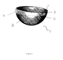
- the prosthesis 1 of the present invention comprises a cup 2 and a titanium band 3 located around the external surface of the cup and adjacent to the rim 4 of the cup 2.
- Ribs 5 are located on the external surface of the band and are configured such that when located in the pelvis torsional movement of the cup in the pelvis is resisted.
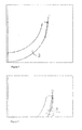
- the shape of the cup 2 before the band 3 is applied is illustrated schematically in Figure 2 .
- the band 3 is shaped so that the hemispherical external surface of the cup is completed.
Abstract
Description
- The present invention relates to a prosthesis. More particularly, it relates to a preassembled acetabular component for a hip prosthesis and a process for the production thereof.
- The efficient functioning of the hip joint is extremely important to the well-being and mobility of the human body. Each hip joint is comprised by the upper portion of the femur which terminates in an offset bony neck surmounted by a ball-headed portion which rotates within the acetabulum in the pelvis. Diseases such as rheumatoid- and osteo-arthritis can cause erosion of the cartilage lining of the acetabulum so that the ball of the femur and the hip bone rub together causing pain and further erosion. Bone erosion may cause the bones themselves to attempt to compensate for the erosion which may result in the bone becoming misshapen.
- Operations to replace the hip joint with an artificial implant are well-known and widely practiced. Generally, the hip prosthesis will be formed of two components, namely: an acetabular component which lines the acetabulum; and a femoral component which replaces the femoral head. The femoral component may be total femoral head replacement in which case the component includes a head, neck and a stem which in use in inserted into the end of a prepared femur. Alternatively, where appropriate, the femoral head component may be a resurfacing prosthesis which is attached to the head of the femur once it has been suitably machined.
- In an operation to insert a prosthetic acetabulum in a patient's pelvis the surgeon first uses a reamer to cut a cavity of appropriate size in the patient's pelvis. An acetabular cup is then inserted into the cavity. By "appropriate size" is meant a size which is selected by the surgeon as being the most appropriate for that particular patient. Normally, it is desirable to retain as much of the original healthy bone surface as possible.
- Commercially available acetabular cups are sold in a range of sizes to suit the needs of individual patients. Generally, acetabular cups are available in sizes of from 42 mm to 62 mm diameter with 2 mm increments between neighboring sizes.
- There are a number of different types of prosthetic acetabular cups. One type of cup is those made from polyethylene. They are generally cemented into the acetabulum and require only light pressure to seat them in the cement.
- One alternative cup type has a polyethylene liner unit for articulation with the femur and a metal shell for insertion into the pelvic cavity. These cups with metal shells may be implanted without cement such that they rely on a jam fit between the metal shell and the patient's acetabulum. However, in some arrangements, screws may be used to secure the cup shell in position in the pelvis before the liner is applied into position. The insertion of the metal shell into the pelvis requires considerable force. As the surgeon applies this force, there is a risk that the metal shell can become damaged or deformed. There is also a possibility that during the application of the force, the shell may be moved so that it is not in the optimum alignment in the acetabulum. Often the metal shells have outer surfaces or coatings which encourage bone to grow into them over time.
- With this type of prosthesis, the polyethylene liner unit is snapped or screwed into the metal shell after the metal shell has been seated in the acetabulum. Thus the inner surface of the liner forms the socket part of the joint.
- More recently, ceramics have been used to as an alternative to the plastics liner. In this arrangement, the metal shell, which is generally formed from titanium and which is of a similar thickness to the arrangement in which a polyethylene liner is used, is inserted into the acetabulum. The ceramic liner is then inserted into the shell. It can be difficult for the liner to be accurately aligned in the shell. In addition, this insertion of the liner does require the application of a considerable force which is usually applied by the surgeon using a mallet often via an insertion tool. Considerable force is generally required to achieve a successful interface. However, this force can damage the ceramic liner.
- In order to get an optimum fit, it is necessary that the forces applied for both the insertion of the metal shell and for the ceramic liner are appropriate but not excessive. One problem however, is that to date there has been no understanding as to what forces are appropriate nor is there a means to ensure that the correct force is applied.
- The surgeon is not generally able to apply a controlled amount of force applied. Some surgeons may not apply sufficient force in one hit and it may be necessary for a plurality of hits to be used. These may not all strike at the same angle and may not each apply the same force. Other surgeons may apply a much greater single strike. The force applied by the surgeon on, for example, an insertion tool may vary considerably and can be of the order of about 3 to 5 kN but can also be much higher and may even be of the order of about 35 kN.
- Whilst very large forces may only be applied for small moments in time, of the order of seconds or fractions of a second, forces of this magnitude, or a plurality of forces of smaller magnitude may cause the shell to be deformed as it is inserted into the acetabulum. This is a particular risk in those arrangements where the thickness of the shell is only from about 1 mm to about 3 mm thick. If the shell is deformed, it can become difficult or even impossible to insert the liner.
- Additionally or alternatively, the liner may be incorrectly seated in the shell which can lead to various disadvantages. Not only is there a risk that where a portion of the liner stands above the rim of the cup, a point of irritation can be produced but also, there is a risk that material, such as wear debris, may congregate against the raised portion of the liner or against the wall of the cup in the area where the liner sits below the rim. This accumulation of debris may provide a site for post-onerative infection Even if the liner is correctly located and the shell is not deformed during the assembly process, it may become deformed on insertion of the prosthesis into the pelvis such that the shell may become spaced from the liner over at least a portion of the prosthesis.
- Even if the surgeon is able to accurately seat the liner in the cup, there is a risk that during assembly debris may be caught between the liner and the cup which may effect the wear properties of the prosthesis. A further problem associated with the presence of debris, which may include fluids such as blood or fat, between the shell and liner is that in use, in vivo the presence of the debris may cause the shell and liner to move apart.
- Without wishing to be bound by any particular theory, it will be understood where the shell and ceramic liner are held together by friction, debris, in particular fatty substances or blood, can interfere with the frictional interface between the outer surface of the liner and the inner surface of the shell such that there is a propensity for the liner to move out of the shell.
- A further problem which may be encountered is that while inserting the liner in the shell it may become damaged. If this damage is a chip or crack on the outer surface of the liner, i.e. on the surface adjacent to the surface of the shell, its presence may not be noticed by the surgeon during assembly. However, its existence will be a point of weakness which can result in the prosthesis failing in use.
- One solution that has been proposed is to provide a preassembled unit acetabular cup prosthesis comprising: an outer shell; and a ceramic liner located within the shell. In one arrangement, the preassembled unit may be assembled ex-vivo under a controlled force selected to optimise the pre-stressing of the components of the prosthesis.
- This arrangement provides acetabular components which reduces the risk of liner misplacement and which has enhanced life expectancy arising, in part, through improved resistance to damage caused during impaction into the acetabulum. It is also desirable to provide an acetabular cup prosthesis which can be easily handled and inserted during surgery without damage to the acetabular cup prosthesis and which minimizes the risk of debris being trapped between the cup and the liner.
- Examples of such preassembled acetabular cup can be found in copending European applications
08103811.9 08103809.3 - In certain arrangements it may be desirable to provide an acetabular cup prosthesis which is made substantially from ceramic.
- Whilst acetabular cup prosthesis made formed from ceramic offer various advantages, they may suffer from various disadvantages. The ceramic may not have sufficient strength to withstand the rigors of insertion. Further even if the ceramic cup can be successfully inserted in the pelvis without damage, due to the structure of the surface there may be little or no torsional stability.
- Even if the acetabular cup does include a thin metal shell, there may be a need to provide additional strength or additional torsional stability.
- Thus according to the present invention there is provided an acetabular cup prosthesis comprising an acetabular cup having a rim and comprising a metal band applied around the outer circumference of the acetabular cup prosthesis and adjacent to said rim.
- The presence of the metal band applied around the outer circumference of the acetabular cup prosthesis and adjacent the rim thereof provides additional strength to the prosthesis and in particular provides the required level of hoop compression.
- The acetabular cup of the present invention may be formed of any suitable material. In a preferred embodiment the suitable material will be a ceramic. For the purposes of this application, the term "ceramic" should be construed as meaning not only true ceramic materials but also other materials which display ceramic-like properties. Ceramic-like properties for the purposes of the present invention are those where strength, stiffness and rigidity are similarto those of ceramics. Examples of suitable materials include glasses. In one arrangement a metal shell may be provided.
- The prosthesis of the present invention provides a prosthesis with improved properties over prior art prosthesis. In particular, the prothesis of the present invention has improved resistance to fracture. In particular where the cup is a ceramic cup or includes a ceramic liner, the presence of the band will serve to pre-stress the ceramic. This pre-stressing occurs during the controlled assembly process. Unstressed ceramic liners such as those of the prior art, are prone to fracture in use. Stressing of the components of the prosthesis is discussed in more detail below.
- The band of the prosthesis is preferably made from metal. Any suitable metal may be used, with titanium being particularly preferred. Cobalt/chromium may also be used. The outer surface of the band may be provided with one or more ribs extending away from the cup. In use these ribs will interact with the pelvis to provide the required torsional stability. In one arrangement one or more, preferably three, ribs may be located at a plurality of points around the circumference of the band. In one arrangement one or more, preferably three ribs, may be located at three equally spaced positions around the circumference.
- The ribs may be of any suitable configuration. Where there is one or more ribs present, the ribs may be of the same or of different configurations. In one arrangement, the or each rib may be a longitudinal extension.
- In one arrangement, the band may be configured on its out surface to promote bone integration. In one arrangement, the outer surface may be coated with a bone growth promoting material such as hydroxyapatite.
- In the embodiment where a shell is used, this may be coated on its outer surface with material to promote bone integration. In one arrangement, the outer surface may be coated with a bone growth promoting material such as hydroxyapatite.
- Although not preferred, where a shell is used it may be a titanium shell. If used, the titanium shell has a thickness in the region of about 1 mm to about 3 mm.
- The ceramic cup or liner may be formed of any material which has acceptable biocompatibility, hardness and wear resistance. Suitable ceramic materials include silicon nitride, doped silicon nitride, an alumina-zirconia ceramic, yttria, stabilized zirconia, ceria, stabilized zirconia, zirconia ceramics, alumina ceramics, oxinium or mixtures thereof. The thickness of the ceramic cup or liner is preferably in the region of from about 2 mm to about 5 mm.
- Where the band is applied directly to the outer surface of a ceramic cup, the ceramic will generally be shaped in the region of the rim where the band is applied such that when the band is in position, the external profile of the prosthesis (ignoring any ribs or other biting configurations) will correspond to that of a ceramic cup prosthesis not having a band. Thus the cup with the band will still have the approximately hemispherical outer configuration.
- It will therefore by understood that the thickness of the band will generally be of the order of a few millimeters. The surface of the band which will be in contact with the cup will generally be flat whereas the outer surface of the band may be curved and as such the shape of the band in cross-section may be D-shaped. At the thickest point it may have a thickness of the order of about 1 mm to about 3 mm.
- The band may be applied to the acetabular cup by any suitable means. In one arrangement, it may be press fitted onto the cup. Since the band is a tight fit on the cup press fitting onto the cup may present difficulties. In one arrangement, the band may be heated to allow it to be correctly fitted. In one arrangement, the heating may be by induction heating. A benefit of induction heating is that only the metal band will be effected and the ceramic cup will not be heated. The induction heating may be carried out by any suitable means. The press fit may require load to be applied. The load required may depend on the temperature to which the band is heated. In one arrangement, heating may be to from about 500 to about 700°C. In one arrangement approximately 5kN load may be used for the press-fitting.
- Thus according to a second aspect of the present invention there is provided a process for forming the acetabular cup prosthesis of the above first aspect comprising the step of heating the band before applying it to the cup.
- Once the band has cooled, the loading of the band on the cup will generally act to pre-stress the cup in an optimum manner such that separation between the band and the cup will not occur. In this connection it will be understood that the band being metal is strong in hoop tension whereas the ceramic cup is strong in hoop compression. With the pre-stressing of the present invention, the tensions are optimised. In particular, the residual stress in the ceramic may be engineered to a value that optimises performance and is compressive. In addition, the compressive interface between the two components is maintained throughout the entirety of the loading of the prosthesis in vivo.
- A further advantage of the present invention is that the acetabular cup prosthesis of the present invention has sufficient strength to withstand the forces supplied during the insertion of the prosthesis into the acetabulum without damage, distortion or separation of the band from the cup. In particular, and surprisingly, the sphericity of the prosthesis is substantially maintained even though the diameter is reduced due to the localised compression at the rim of the liner.
- The prosthesis of the present invention may be provided with an impaction cap. The impaction cap may be pre-assembled with the prosthesis as described in
EP2008618 which is incorporated herein by reference. In one arrangement the impaction cup is configured such that the force applied to impact the prosthesis into the acetabulum is directed via the ceramic cup so that any shock passing through the metal band is minimised. - The present invention will now be described, by way of example, with reference to the accompanying drawings in which:
- Figure 1
- is a perspective view of the acetabular cup prosthesis if the present invention;
- Figure 2
- is a schematic diagram of a cross section through a cup prepared to accept the band; and
- Figure 3
- is a schematic diagram of a cross section through a portion of a an acetabular cup prosthesis of the present invention including the band;
- As illustrated in
Figure 1 , the prosthesis 1 of the present invention comprises acup 2 and atitanium band 3 located around the external surface of the cup and adjacent to the rim 4 of thecup 2. Ribs 5 are located on the external surface of the band and are configured such that when located in the pelvis torsional movement of the cup in the pelvis is resisted. - The shape of the
cup 2 before theband 3 is applied is illustrated schematically inFigure 2 . As illustrated inFigure 3 , theband 3 is shaped so that the hemispherical external surface of the cup is completed.
Claims (10)
- An acetabular cup prosthesis comprising an acetabular cup having a rim and comprising a metal band applied around the outer circumference of the acetabular cup prosthesis and adjacent to said rim.
- An acetabular cup according to Claim 1 wherein the acetabular cup is formed from ceramic.
- An acetabular cup according to Claim 1 or 2 wherein the band of the prosthesis is made from metal.
- An acetabular cup according to Claim 3 wherein the metal is titanium.
- An acetabular cup according to any one of Claims 1 to 4 wherein the outer surface of the band is provided with ribs extending away from the cup.
- An acetabular cup according to any one of Claims 1 to 5 wherein the shape of the band in cross-section is D-shaped.
- An acetabular cup according to Claim 6 wherein the band at the thickest point has a thickness of from about 1 mm to about 3 mm
- A method of forming the acetabular cup prosthesis of any one of Claims I to 7 wherein the band is press fitted onto the cup.
- A method according to Claim 8 wherein the band is heated prior to or during press fitting.
- A method according to Claim 9 wherein the heating is achieved by induction heating.
Priority Applications (1)
| Application Number | Priority Date | Filing Date | Title |
|---|---|---|---|
| EP12183609.2A EP2561832B1 (en) | 2008-10-07 | 2009-09-08 | Prosthesis |
Applications Claiming Priority (2)
| Application Number | Priority Date | Filing Date | Title |
|---|---|---|---|
| GB0818326A GB0818326D0 (en) | 2008-10-07 | 2008-10-07 | Prosthesis |
| GB0818505A GB0818505D0 (en) | 2008-10-09 | 2008-10-09 | Prosthesis |
Related Child Applications (2)
| Application Number | Title | Priority Date | Filing Date |
|---|---|---|---|
| EP12183609.2A Division EP2561832B1 (en) | 2008-10-07 | 2009-09-08 | Prosthesis |
| EP12183609.2 Division-Into | 2012-09-07 |
Publications (2)
| Publication Number | Publication Date |
|---|---|
| EP2174621A1 true EP2174621A1 (en) | 2010-04-14 |
| EP2174621B1 EP2174621B1 (en) | 2013-07-17 |
Family
ID=41557659
Family Applications (2)
| Application Number | Title | Priority Date | Filing Date |
|---|---|---|---|
| EP09169709.4A Active EP2174621B1 (en) | 2008-10-07 | 2009-09-08 | Prosthesis |
| EP12183609.2A Active EP2561832B1 (en) | 2008-10-07 | 2009-09-08 | Prosthesis |
Family Applications After (1)
| Application Number | Title | Priority Date | Filing Date |
|---|---|---|---|
| EP12183609.2A Active EP2561832B1 (en) | 2008-10-07 | 2009-09-08 | Prosthesis |
Country Status (2)
| Country | Link |
|---|---|
| US (2) | US8372155B2 (en) |
| EP (2) | EP2174621B1 (en) |
Cited By (6)
| Publication number | Priority date | Publication date | Assignee | Title |
|---|---|---|---|---|
| WO2010146398A1 (en) | 2009-06-18 | 2010-12-23 | Finsbury (Development) Limited | Prosthesis |
| WO2011146509A2 (en) * | 2010-05-17 | 2011-11-24 | Smith & Nephew Inc. | Liner deformation compensation in an acetabular assembly |
| WO2013076484A1 (en) | 2011-11-23 | 2013-05-30 | Depuy (Ireland) | Medical implant, instrument head and assembly |
| WO2013076485A1 (en) | 2011-11-23 | 2013-05-30 | Depuy (Ireland) | Medical implant, instrument head and assembly |
| WO2018206931A3 (en) * | 2017-05-09 | 2019-02-14 | Matortho Limited | Ceramic acetabular cup |
| WO2022084659A3 (en) * | 2020-10-19 | 2022-06-23 | Inixio Limited | Prostheses |
Families Citing this family (12)
| Publication number | Priority date | Publication date | Assignee | Title |
|---|---|---|---|---|
| FR2950525B1 (en) * | 2009-09-28 | 2013-05-10 | Thomas Gradel | HIP PROTHETIC COTYL WITH EXTERNAL FASTENING |
| US10094364B2 (en) | 2015-03-24 | 2018-10-09 | Ocean Pacific Technologies | Banded ceramic valve and/or port plate |
| USD858768S1 (en) * | 2016-08-26 | 2019-09-03 | Surgical Device Innovations, LLC | Acetabular device |
| US11000378B2 (en) | 2017-02-14 | 2021-05-11 | Surgical Device Innovations, LLC | Acetabular surgical implant for segmental pelvic defect and methods of use and manufacture |
| US10849759B2 (en) | 2017-03-13 | 2020-12-01 | Floyd G. Goodman | Ceramic multi-hooded enarthrodial joint implant |
| US11583405B2 (en) | 2017-03-13 | 2023-02-21 | Floyd G. Goodman | Hard substance multi-hooded enarthrodial joint implant |
| USD851765S1 (en) * | 2017-11-15 | 2019-06-18 | Joint Innovation Technology, Llc | Acetabular cup liner |
| USD919089S1 (en) * | 2017-11-15 | 2021-05-11 | Joint Innovation Technology, Llc. | Acetabular cup liner |
| USD851764S1 (en) * | 2017-11-15 | 2019-06-18 | Joint Innovation Technology, Llc | Acetabular cup liner |
| USD922579S1 (en) * | 2017-11-15 | 2021-06-15 | Joint Innovation Technology, Llc. | Acetabular cup liner |
| USD847997S1 (en) * | 2017-11-15 | 2019-05-07 | Joint Innovation Technology, Llc | Acetabular cup liner |
| US11628066B2 (en) * | 2019-12-11 | 2023-04-18 | Depuy Ireland Unlimited Company | Ceramic acetabular shell liner with a metal ring having a lead-in surface |
Citations (15)
| Publication number | Priority date | Publication date | Assignee | Title |
|---|---|---|---|---|
| US4166292A (en) | 1977-09-08 | 1979-09-04 | Carbomedics, Inc. | Stress reinforced artificial joint prostheses |
| EP0532439A2 (en) | 1991-09-13 | 1993-03-17 | Impact | Acetabular cup for hip prosthesis |
| US5405402A (en) | 1993-04-14 | 1995-04-11 | Intermedics Orthopedics, Inc. | Implantable prosthesis with radiographic marker |
| FR2735356A1 (en) | 1995-06-16 | 1996-12-20 | Tornier Sa | COTYLOID IMPLANT INTENDED IN PARTICULAR FOR ILIAC JOINT CAVITY |
| EP0810381A1 (en) | 1996-05-31 | 1997-12-03 | Koyo Seiko Co., Ltd. | Pressed cage for a ball bearing |
| EP0810380A2 (en) | 1996-05-27 | 1997-12-03 | Nippon Thompson Co., Ltd. | Seal structure-carrying linear motion rolling guide unit |
| FR2749162A1 (en) | 1996-05-31 | 1997-12-05 | Fauvy Alain | Cotyloidal hip joint prosthesis |
| DE19640747A1 (en) | 1996-07-30 | 1998-02-05 | Cerasiv Gmbh | Hip joint replacement implant |
| US6022357A (en) | 1997-03-03 | 2000-02-08 | Aesculap Ag & Co. Kg | Surgical instrument |
| DE10006098A1 (en) | 1999-02-12 | 2000-09-07 | Alain Fauvy | Acetabular prosthesis |
| FR2825911A1 (en) | 2001-06-19 | 2002-12-20 | Roland Petit | Cotyloidal implant has outer shell and inset with mating lugs to position them together |
| EP1290992A1 (en) | 2001-09-11 | 2003-03-12 | Benoist Girard Sas | Acetabular cup |
| EP1433443A1 (en) | 2002-12-27 | 2004-06-30 | Biomet Merck Limited | Hip prosthesis with ceramic bearing |
| EP2008620A2 (en) | 2007-06-26 | 2008-12-31 | Finsbury (Development) Limited | Prosthesis |
| EP2008619A2 (en) * | 2007-06-26 | 2008-12-31 | Finsbury (Development) Limited | Prosthesis |
Family Cites Families (25)
| Publication number | Priority date | Publication date | Assignee | Title |
|---|---|---|---|---|
| FR2096895B1 (en) | 1970-07-10 | 1973-01-12 | Electro Ceramique Cie Gl | |
| FR2301217A2 (en) | 1975-02-21 | 1976-09-17 | Ceraver | Hip prosthesis in alumina - with acetabular part having ridge and grooved anchoring heads |
| FR2377798A2 (en) | 1977-01-20 | 1978-08-18 | Ceraver | Surgical prosthesis for hip - has three peripheral dowels and central dowel with key grooves on outer convex surface of acetabular cap |
| FR2429009A1 (en) * | 1978-06-21 | 1980-01-18 | Roux Christiane | PROSTHESIS FOR ARTICULATION, PARTICULARLY COXO-FEMORAL, ARTIFICIAL |
| IT1202437B (en) * | 1987-01-28 | 1989-02-09 | Cremascoli Spa G | STRUCTURE OF TOTAL ANCHOR PROSTHESIS, INCLUDING A FEMORAL COMPONENT AND AN ACETABULAR COMPONENT, REALIZED, BOTH, PART IN METAL MATERIAL AND PART IN CERAMIC MATERIAL |
| US5218975A (en) * | 1991-10-25 | 1993-06-15 | Prostkoff Melvin E | Cranial prosthesis |
| FR2706284B1 (en) | 1993-06-17 | 1995-09-29 | Roux Christiane | Cotyloid prosthesis, in particular for coxo-femoral articulation. |
| DE4335931B4 (en) * | 1993-10-21 | 2006-10-12 | Cerasiv Gmbh Innovatives Keramik-Engineering | acetabulum |
| CH687436A5 (en) | 1994-07-28 | 1996-12-13 | Werner Hermann | Socket part of the hip joint prosthesis. |
| DE4437479A1 (en) | 1994-10-20 | 1996-05-02 | Volker Prof Dr Echtermeyer | Endoprosthesis for hip or knee joint |
| DE29513694U1 (en) * | 1995-08-25 | 1997-01-02 | Link Waldemar Gmbh Co | Joint socket for an endoprosthesis |
| DE19615786A1 (en) | 1996-04-20 | 1997-10-23 | Cerasiv Gmbh | Prosthetic socket |
| US6152961A (en) * | 1997-12-29 | 2000-11-28 | Depuy Orthopaedics, Inc. | Acetabular prosthesis assembly |
| AU2695799A (en) * | 1998-05-22 | 1999-12-02 | Howmedica Osteonics Corp. | Acetabular cup assembly with selected bearing |
| FR2781364B1 (en) * | 1998-07-24 | 2000-11-24 | Michel Henry Fessy | COTYL FOR HIP PROSTHESIS |
| DE19926923A1 (en) * | 1999-06-14 | 2000-12-21 | Ceramtec Ag | Modular socket for a ball joint prosthesis |
| FR2796266B1 (en) | 1999-07-13 | 2001-08-10 | Merck Biomaterial France | COTYL FOR HIP PROSTHESIS |
| AU783205C (en) * | 2000-03-15 | 2006-08-17 | Depuy Orthopaedics, Inc. | Prosthetic cup assembly which includes components possessing self-locking taper |
| US7695521B2 (en) | 2001-05-01 | 2010-04-13 | Amedica Corporation | Hip prosthesis with monoblock ceramic acetabular cup |
| CN1596091A (en) * | 2001-12-04 | 2005-03-16 | 迪斯酋有限公司 | Implants for load bearing applications |
| US7267693B1 (en) * | 2003-12-08 | 2007-09-11 | Orthopedic Source, Inc. | Locking ring for liner of acetabular cup |
| EP1722719B1 (en) * | 2004-03-11 | 2016-04-27 | Smith & Nephew, Inc | Universal liner assembly for joint replacement |
| US20050288793A1 (en) * | 2004-06-28 | 2005-12-29 | Howmedica Osteonics Corp. | Internal fixation element for hip acetabular shell |
| US20060190089A1 (en) * | 2005-02-18 | 2006-08-24 | Howmedica Osteonics Corp. | Internal adaptor for hip acetabular cage |
| EP2008618A1 (en) | 2007-06-26 | 2008-12-31 | Finsbury (Development) Limited | Prosthesis |
-
2009
- 2009-09-08 EP EP09169709.4A patent/EP2174621B1/en active Active
- 2009-09-08 EP EP12183609.2A patent/EP2561832B1/en active Active
- 2009-10-01 US US12/572,039 patent/US8372155B2/en active Active
-
2013
- 2013-01-09 US US13/737,218 patent/US9339389B2/en active Active
Patent Citations (16)
| Publication number | Priority date | Publication date | Assignee | Title |
|---|---|---|---|---|
| US4166292A (en) | 1977-09-08 | 1979-09-04 | Carbomedics, Inc. | Stress reinforced artificial joint prostheses |
| EP0532439A2 (en) | 1991-09-13 | 1993-03-17 | Impact | Acetabular cup for hip prosthesis |
| US5405402A (en) | 1993-04-14 | 1995-04-11 | Intermedics Orthopedics, Inc. | Implantable prosthesis with radiographic marker |
| FR2735356A1 (en) | 1995-06-16 | 1996-12-20 | Tornier Sa | COTYLOID IMPLANT INTENDED IN PARTICULAR FOR ILIAC JOINT CAVITY |
| EP0810380A2 (en) | 1996-05-27 | 1997-12-03 | Nippon Thompson Co., Ltd. | Seal structure-carrying linear motion rolling guide unit |
| EP0810381A1 (en) | 1996-05-31 | 1997-12-03 | Koyo Seiko Co., Ltd. | Pressed cage for a ball bearing |
| FR2749162A1 (en) | 1996-05-31 | 1997-12-05 | Fauvy Alain | Cotyloidal hip joint prosthesis |
| DE19640747A1 (en) | 1996-07-30 | 1998-02-05 | Cerasiv Gmbh | Hip joint replacement implant |
| US6022357A (en) | 1997-03-03 | 2000-02-08 | Aesculap Ag & Co. Kg | Surgical instrument |
| DE10006098A1 (en) | 1999-02-12 | 2000-09-07 | Alain Fauvy | Acetabular prosthesis |
| FR2825911A1 (en) | 2001-06-19 | 2002-12-20 | Roland Petit | Cotyloidal implant has outer shell and inset with mating lugs to position them together |
| EP1290992A1 (en) | 2001-09-11 | 2003-03-12 | Benoist Girard Sas | Acetabular cup |
| EP1433443A1 (en) | 2002-12-27 | 2004-06-30 | Biomet Merck Limited | Hip prosthesis with ceramic bearing |
| EP2008620A2 (en) | 2007-06-26 | 2008-12-31 | Finsbury (Development) Limited | Prosthesis |
| EP2008619A2 (en) * | 2007-06-26 | 2008-12-31 | Finsbury (Development) Limited | Prosthesis |
| US20090005879A1 (en) * | 2007-06-26 | 2009-01-01 | Finsbury (Development) Limited | Prosthesis |
Cited By (12)
| Publication number | Priority date | Publication date | Assignee | Title |
|---|---|---|---|---|
| WO2010146398A1 (en) | 2009-06-18 | 2010-12-23 | Finsbury (Development) Limited | Prosthesis |
| EP2684542A1 (en) * | 2009-06-18 | 2014-01-15 | Finsbury (Development) Limited | Prosthesis |
| US8845747B2 (en) | 2009-06-18 | 2014-09-30 | Finsbury (Development) Limited | Prosthesis |
| WO2011146509A2 (en) * | 2010-05-17 | 2011-11-24 | Smith & Nephew Inc. | Liner deformation compensation in an acetabular assembly |
| WO2011146509A3 (en) * | 2010-05-17 | 2012-03-01 | Smith & Nephew Inc. | Liner deformation compensation in an acetabular assembly |
| WO2013076484A1 (en) | 2011-11-23 | 2013-05-30 | Depuy (Ireland) | Medical implant, instrument head and assembly |
| WO2013076485A1 (en) | 2011-11-23 | 2013-05-30 | Depuy (Ireland) | Medical implant, instrument head and assembly |
| WO2013076483A1 (en) | 2011-11-23 | 2013-05-30 | Depuy (Ireland) | Surgical instrument head and assembly including tab separation member |
| WO2018206931A3 (en) * | 2017-05-09 | 2019-02-14 | Matortho Limited | Ceramic acetabular cup |
| US11540923B2 (en) | 2017-05-09 | 2023-01-03 | Matortho Limited | Ceramic acetabular cup |
| EP4223259A1 (en) * | 2017-05-09 | 2023-08-09 | MatOrtho Limited | Ceramic acetabular cup |
| WO2022084659A3 (en) * | 2020-10-19 | 2022-06-23 | Inixio Limited | Prostheses |
Also Published As
| Publication number | Publication date |
|---|---|
| EP2174621B1 (en) | 2013-07-17 |
| EP2561832B1 (en) | 2015-10-21 |
| US20100087930A1 (en) | 2010-04-08 |
| US20130123932A1 (en) | 2013-05-16 |
| US8372155B2 (en) | 2013-02-12 |
| US9339389B2 (en) | 2016-05-17 |
| EP2561832A1 (en) | 2013-02-27 |
Similar Documents
| Publication | Publication Date | Title |
|---|---|---|
| US9339389B2 (en) | Acetabular cup prosthesis and method of forming the prosthesis | |
| EP2442754B1 (en) | Prosthesis | |
| AU2011247048B2 (en) | Prosthesis | |
| US20090005879A1 (en) | Prosthesis | |
| EP2008619B1 (en) | Prosthesis | |
| EP2108338A2 (en) | Resurfacing femoral head component | |
| EP3236886B1 (en) | Prosthesis | |
| US20090248168A1 (en) | Prosthesis | |
| AU2014271270B2 (en) | Prosthesis | |
| WO2017212243A1 (en) | Prosthesis |
Legal Events
| Date | Code | Title | Description |
|---|---|---|---|
| PUAI | Public reference made under article 153(3) epc to a published international application that has entered the european phase |
Free format text: ORIGINAL CODE: 0009012 |
|
| AK | Designated contracting states |
Kind code of ref document: A1 Designated state(s): AT BE BG CH CY CZ DE DK EE ES FI FR GB GR HR HU IE IS IT LI LT LU LV MC MK MT NL NO PL PT RO SE SI SK SM TR |
|
| AX | Request for extension of the european patent |
Extension state: AL BA RS |
|
| 17P | Request for examination filed |
Effective date: 20100806 |
|
| 17Q | First examination report despatched |
Effective date: 20100907 |
|
| TPAC | Observations filed by third parties |
Free format text: ORIGINAL CODE: EPIDOSNTIPA |
|
| TPAC | Observations filed by third parties |
Free format text: ORIGINAL CODE: EPIDOSNTIPA |
|
| GRAP | Despatch of communication of intention to grant a patent |
Free format text: ORIGINAL CODE: EPIDOSNIGR1 |
|
| RIC1 | Information provided on ipc code assigned before grant |
Ipc: A61F 2/00 20060101ALN20130116BHEP Ipc: A61F 2/34 20060101AFI20130116BHEP |
|
| RIC1 | Information provided on ipc code assigned before grant |
Ipc: A61F 2/34 20060101AFI20130121BHEP Ipc: A61F 2/00 20060101ALN20130121BHEP |
|
| RIN1 | Information on inventor provided before grant (corrected) |
Inventor name: TUKE, MICHAEL ANTONY Inventor name: TAYLOR, ANDREW CLIVE |
|
| GRAS | Grant fee paid |
Free format text: ORIGINAL CODE: EPIDOSNIGR3 |
|
| GRAA | (expected) grant |
Free format text: ORIGINAL CODE: 0009210 |
|
| AK | Designated contracting states |
Kind code of ref document: B1 Designated state(s): AT BE BG CH CY CZ DE DK EE ES FI FR GB GR HR HU IE IS IT LI LT LU LV MC MK MT NL NO PL PT RO SE SI SK SM TR |
|
| REG | Reference to a national code |
Ref country code: GB Ref legal event code: FG4D |
|
| REG | Reference to a national code |
Ref country code: CH Ref legal event code: EP Ref country code: CH Ref legal event code: NV Representative=s name: E. BLUM AND CO. AG PATENT- UND MARKENANWAELTE , CH |
|
| REG | Reference to a national code |
Ref country code: IE Ref legal event code: FG4D |
|
| REG | Reference to a national code |
Ref country code: AT Ref legal event code: REF Ref document number: 621692 Country of ref document: AT Kind code of ref document: T Effective date: 20130815 |
|
| REG | Reference to a national code |
Ref country code: DE Ref legal event code: R096 Ref document number: 602009017174 Country of ref document: DE Effective date: 20130912 |
|
| REG | Reference to a national code |
Ref country code: AT Ref legal event code: MK05 Ref document number: 621692 Country of ref document: AT Kind code of ref document: T Effective date: 20130717 |
|
| REG | Reference to a national code |
Ref country code: NL Ref legal event code: VDEP Effective date: 20130717 |
|
| REG | Reference to a national code |
Ref country code: LT Ref legal event code: MG4D |
|
| PG25 | Lapsed in a contracting state [announced via postgrant information from national office to epo] |
Ref country code: NO Free format text: LAPSE BECAUSE OF FAILURE TO SUBMIT A TRANSLATION OF THE DESCRIPTION OR TO PAY THE FEE WITHIN THE PRESCRIBED TIME-LIMIT Effective date: 20131017 Ref country code: LT Free format text: LAPSE BECAUSE OF FAILURE TO SUBMIT A TRANSLATION OF THE DESCRIPTION OR TO PAY THE FEE WITHIN THE PRESCRIBED TIME-LIMIT Effective date: 20130717 Ref country code: BE Free format text: LAPSE BECAUSE OF FAILURE TO SUBMIT A TRANSLATION OF THE DESCRIPTION OR TO PAY THE FEE WITHIN THE PRESCRIBED TIME-LIMIT Effective date: 20130717 Ref country code: HR Free format text: LAPSE BECAUSE OF FAILURE TO SUBMIT A TRANSLATION OF THE DESCRIPTION OR TO PAY THE FEE WITHIN THE PRESCRIBED TIME-LIMIT Effective date: 20130717 Ref country code: IS Free format text: LAPSE BECAUSE OF FAILURE TO SUBMIT A TRANSLATION OF THE DESCRIPTION OR TO PAY THE FEE WITHIN THE PRESCRIBED TIME-LIMIT Effective date: 20131117 Ref country code: PT Free format text: LAPSE BECAUSE OF FAILURE TO SUBMIT A TRANSLATION OF THE DESCRIPTION OR TO PAY THE FEE WITHIN THE PRESCRIBED TIME-LIMIT Effective date: 20131118 Ref country code: AT Free format text: LAPSE BECAUSE OF FAILURE TO SUBMIT A TRANSLATION OF THE DESCRIPTION OR TO PAY THE FEE WITHIN THE PRESCRIBED TIME-LIMIT Effective date: 20130717 Ref country code: SE Free format text: LAPSE BECAUSE OF FAILURE TO SUBMIT A TRANSLATION OF THE DESCRIPTION OR TO PAY THE FEE WITHIN THE PRESCRIBED TIME-LIMIT Effective date: 20130717 Ref country code: CY Free format text: LAPSE BECAUSE OF FAILURE TO SUBMIT A TRANSLATION OF THE DESCRIPTION OR TO PAY THE FEE WITHIN THE PRESCRIBED TIME-LIMIT Effective date: 20130821 |
|
| PG25 | Lapsed in a contracting state [announced via postgrant information from national office to epo] |
Ref country code: NL Free format text: LAPSE BECAUSE OF FAILURE TO SUBMIT A TRANSLATION OF THE DESCRIPTION OR TO PAY THE FEE WITHIN THE PRESCRIBED TIME-LIMIT Effective date: 20130717 Ref country code: SI Free format text: LAPSE BECAUSE OF FAILURE TO SUBMIT A TRANSLATION OF THE DESCRIPTION OR TO PAY THE FEE WITHIN THE PRESCRIBED TIME-LIMIT Effective date: 20130717 Ref country code: PL Free format text: LAPSE BECAUSE OF FAILURE TO SUBMIT A TRANSLATION OF THE DESCRIPTION OR TO PAY THE FEE WITHIN THE PRESCRIBED TIME-LIMIT Effective date: 20130717 Ref country code: ES Free format text: LAPSE BECAUSE OF FAILURE TO SUBMIT A TRANSLATION OF THE DESCRIPTION OR TO PAY THE FEE WITHIN THE PRESCRIBED TIME-LIMIT Effective date: 20131028 Ref country code: GR Free format text: LAPSE BECAUSE OF FAILURE TO SUBMIT A TRANSLATION OF THE DESCRIPTION OR TO PAY THE FEE WITHIN THE PRESCRIBED TIME-LIMIT Effective date: 20131018 Ref country code: LV Free format text: LAPSE BECAUSE OF FAILURE TO SUBMIT A TRANSLATION OF THE DESCRIPTION OR TO PAY THE FEE WITHIN THE PRESCRIBED TIME-LIMIT Effective date: 20130717 Ref country code: FI Free format text: LAPSE BECAUSE OF FAILURE TO SUBMIT A TRANSLATION OF THE DESCRIPTION OR TO PAY THE FEE WITHIN THE PRESCRIBED TIME-LIMIT Effective date: 20130717 |
|
| PG25 | Lapsed in a contracting state [announced via postgrant information from national office to epo] |
Ref country code: CY Free format text: LAPSE BECAUSE OF FAILURE TO SUBMIT A TRANSLATION OF THE DESCRIPTION OR TO PAY THE FEE WITHIN THE PRESCRIBED TIME-LIMIT Effective date: 20130717 |
|
| PG25 | Lapsed in a contracting state [announced via postgrant information from national office to epo] |
Ref country code: CZ Free format text: LAPSE BECAUSE OF FAILURE TO SUBMIT A TRANSLATION OF THE DESCRIPTION OR TO PAY THE FEE WITHIN THE PRESCRIBED TIME-LIMIT Effective date: 20130717 Ref country code: SK Free format text: LAPSE BECAUSE OF FAILURE TO SUBMIT A TRANSLATION OF THE DESCRIPTION OR TO PAY THE FEE WITHIN THE PRESCRIBED TIME-LIMIT Effective date: 20130717 Ref country code: RO Free format text: LAPSE BECAUSE OF FAILURE TO SUBMIT A TRANSLATION OF THE DESCRIPTION OR TO PAY THE FEE WITHIN THE PRESCRIBED TIME-LIMIT Effective date: 20130717 Ref country code: MC Free format text: LAPSE BECAUSE OF FAILURE TO SUBMIT A TRANSLATION OF THE DESCRIPTION OR TO PAY THE FEE WITHIN THE PRESCRIBED TIME-LIMIT Effective date: 20130717 Ref country code: EE Free format text: LAPSE BECAUSE OF FAILURE TO SUBMIT A TRANSLATION OF THE DESCRIPTION OR TO PAY THE FEE WITHIN THE PRESCRIBED TIME-LIMIT Effective date: 20130717 Ref country code: DK Free format text: LAPSE BECAUSE OF FAILURE TO SUBMIT A TRANSLATION OF THE DESCRIPTION OR TO PAY THE FEE WITHIN THE PRESCRIBED TIME-LIMIT Effective date: 20130717 |
|
| PLBE | No opposition filed within time limit |
Free format text: ORIGINAL CODE: 0009261 |
|
| STAA | Information on the status of an ep patent application or granted ep patent |
Free format text: STATUS: NO OPPOSITION FILED WITHIN TIME LIMIT |
|
| PG25 | Lapsed in a contracting state [announced via postgrant information from national office to epo] |
Ref country code: IT Free format text: LAPSE BECAUSE OF FAILURE TO SUBMIT A TRANSLATION OF THE DESCRIPTION OR TO PAY THE FEE WITHIN THE PRESCRIBED TIME-LIMIT Effective date: 20130717 |
|
| 26N | No opposition filed |
Effective date: 20140422 |
|
| REG | Reference to a national code |
Ref country code: DE Ref legal event code: R097 Ref document number: 602009017174 Country of ref document: DE Effective date: 20140422 |
|
| PG25 | Lapsed in a contracting state [announced via postgrant information from national office to epo] |
Ref country code: SM Free format text: LAPSE BECAUSE OF FAILURE TO SUBMIT A TRANSLATION OF THE DESCRIPTION OR TO PAY THE FEE WITHIN THE PRESCRIBED TIME-LIMIT Effective date: 20130717 |
|
| PG25 | Lapsed in a contracting state [announced via postgrant information from national office to epo] |
Ref country code: TR Free format text: LAPSE BECAUSE OF FAILURE TO SUBMIT A TRANSLATION OF THE DESCRIPTION OR TO PAY THE FEE WITHIN THE PRESCRIBED TIME-LIMIT Effective date: 20130717 Ref country code: MT Free format text: LAPSE BECAUSE OF FAILURE TO SUBMIT A TRANSLATION OF THE DESCRIPTION OR TO PAY THE FEE WITHIN THE PRESCRIBED TIME-LIMIT Effective date: 20130717 |
|
| PG25 | Lapsed in a contracting state [announced via postgrant information from national office to epo] |
Ref country code: MK Free format text: LAPSE BECAUSE OF FAILURE TO SUBMIT A TRANSLATION OF THE DESCRIPTION OR TO PAY THE FEE WITHIN THE PRESCRIBED TIME-LIMIT Effective date: 20130717 Ref country code: BG Free format text: LAPSE BECAUSE OF FAILURE TO SUBMIT A TRANSLATION OF THE DESCRIPTION OR TO PAY THE FEE WITHIN THE PRESCRIBED TIME-LIMIT Effective date: 20130717 Ref country code: HU Free format text: LAPSE BECAUSE OF FAILURE TO SUBMIT A TRANSLATION OF THE DESCRIPTION OR TO PAY THE FEE WITHIN THE PRESCRIBED TIME-LIMIT; INVALID AB INITIO Effective date: 20090908 Ref country code: LU Free format text: LAPSE BECAUSE OF NON-PAYMENT OF DUE FEES Effective date: 20130908 |
|
| REG | Reference to a national code |
Ref country code: FR Ref legal event code: PLFP Year of fee payment: 8 |
|
| REG | Reference to a national code |
Ref country code: FR Ref legal event code: PLFP Year of fee payment: 9 |
|
| REG | Reference to a national code |
Ref country code: FR Ref legal event code: PLFP Year of fee payment: 10 |
|
| PGFP | Annual fee paid to national office [announced via postgrant information from national office to epo] |
Ref country code: IE Payment date: 20230809 Year of fee payment: 15 Ref country code: GB Payment date: 20230803 Year of fee payment: 15 |
|
| PGFP | Annual fee paid to national office [announced via postgrant information from national office to epo] |
Ref country code: FR Payment date: 20230808 Year of fee payment: 15 Ref country code: DE Payment date: 20230802 Year of fee payment: 15 |
|
| PGFP | Annual fee paid to national office [announced via postgrant information from national office to epo] |
Ref country code: CH Payment date: 20231001 Year of fee payment: 15 |